

Page 1
I.
}('"
.~
~i
()
C'
C
()
J
C·
C}:
(~
. /
-
-
-
- -
-
-
-
-
- -
- -
-
-
-
-
-
--
- -
---
---
,
--
-
Maintenance Li. rary
I
~
i
>
j
~
i
t
c.
(-'
i'
1
"\:
(
./
£\
C\
()
£1
.y'
£,J;
C:
C!
- -
----
----
--
--
--
--
----
-----
- - -
-
- -
- - - - -
----
-
--
-
-
----
---
--
---
----
----
- -
Color Display Console
Maintenance Information
...
~'
~
--
SY18-2121-1
Page 2
...
1\
.
'",
\'
'
";:
,
C
o
Second
This
Changes
by a
IBM
customer
of
representations
It
information
programming,
Such
that
services
Publications
requests
representative
locality.
A form
pUblication;
ad'dressed
Mechanicsburg,
the
without
ccmtinue
©
1985
Edition,
major
or
vertical
has
the
is
references
IBM
information
Copyright
additions
prepared
engineers
specific
possible
intends
in
for
for
to
incurring
to
revision
about,
your
reader's
use
(September,
obsoletes
line
to
this
in
machines
that
that
this
or
are
IBM
if
IBM
IBM
services
or
information
to
announce
country.
not
pUblications
or
to
comments.
the
form
Corporation,
PA
17055
you
supply
any
the
information
International
1985)
to
the
the
maintenance
the
it
stocked
the
obligation
text
left
installation,
indicated.
is
suitable
material
products
that
such
at
IBM
branch
is
has
been
U.S.A.
in
Business
SYl8-2l2l-0
and
of
the
manual
for
may
(machines
are
not
must
not
IBM
the
should
Department
any
address
office
provided
removed, comments
IBM
may
way
whatever.
you
supply.
and
illustrations
change.
for
maintenance,
IBM
makes no
any
contain
and
announced
be
products,
be
made
at
6Rl
use
it
believes
Machines
SN18-2262 (TNL).
are
the
use
of
or
other
construed
given
serving
the
or
You
purpose.
reference
programs),
in
your
to
programming,
belowl
to
your
back
J,
distribute
may,
Corporation
IBM
your
of
may
180 Kost Road,
appropriate
of
indicated
IBM
repair
to,
or
country.
mean
or
this
be
any
course,
1984,
of
(
\
'\.
'.
f~.
,;"
,·
C
-.-/
:
)
Page 3
----------_._-------"---_.
-.----.---.--~-----
---------.---.----~~-"-.".
SAFETY
CAUTION
•
. •
•
•
•
(/
(
(~'
NOTICE
To
avoid
exchanging any
CRTs
sa~ety
Do
not
Do
not
The
power attachment
console
standards.
grounded
voltage
electrical
are
under vacuum.
glasses
power
adjust
and meets
For your
receptacle.
on
accessible
on
shock,
FRU.
and
long-sleeved
without
inside
the
turn
All
rear
o~
the
cable
sa~ety,
metal
plug
relevant
An
improperly wired
power
persons
clothing
cover.
video
testing
the
parts
o~~
working
unit.
(when
supplied)
o~
the
laboratory,
plug must
and
disconnect
near
(or
comparable
is
be
connected
receptacle
work
station.
the
an exposed
protection).
approved
country,
to a properly
could
power plug
CRT
should wear
~or
use
or
test-house
place
a hazardous
be~ore
with
this
wired and
(~
L
c;
(/
r·
,
C'
Safety
---~-.-------.---
.
••
Notice
1
~
" J
iii'
-;;'~;'~
Ift.·i
> (
)!'
.
. . .
Page 4
---~.---.-
...
--~----
(..'
Rules
If
electrical and mechanical equipment and
observe the rules, you can
for
Safety
(1)
you know the safety rules for working with
(2)
work safely with IBM
equipment.
Do
not
fear
electricity,
but
respect it.
While you are maintaining IBM equipment,
(1)
observe every safety precaution possible and
(2)
observe the following safety rules.
Work
•
Environment
Do
not work alone
near equipment
in
hazardous conditions or
that
has dangerous voltages.
Always inform your manager if the conditions or
voltages are a possible problem.
• Always look for possible hazards
in
your work
environment. Examples of hazards are: moist
floors, nongrounded extension cables, power
surges, and missing safety grounds.
•
Do
not perform any action
product unsafe or
that
that
makes the
causes hazards for the
customer personnel.
you
• Always keep your CSR tool kit away from walk
areas so
that
other persons cannot trip over it.
For example, keep the kit under a desk or table.
• Observe good housekeeping practices
in
the
area
of the machines while you are performing
maintenance and after completing it.
• After maintenance, reinstall all safety devices,
such as guards, shields, labels, and ground wires.
that
Exchange safety devices
are worn or
defective. (Remember: the safety devices protect
you from a hazard.
you
do
not reinstall them when you have
You destroy their purpose if
completed the service call.)
Electrical Safety
•
If
possible, always unplug the power·supply cable
before you work on a machine. When you switch
off power
off position or attach a
(Z229·0237)
Note: A
may be powered from another source and may be
controlled
breaker.
at
the wall box, lock the switch in the
DO
NOT OPERATE
tag
to the switch.
non·IBM attachment to an IBM machine
by
a different switch or circuit
,-
..
)
• Before you
CSRs and customer personnel are not
start
the equipment, ensure that other
in
a
hazardous position.
•
Do
not wear loose clothing that can be trapped in
that
the moving parts of a machine. Ensure
the
sleeves of your clothing are fastened or are rolled
above the elbow.
If
your hair
is
long, or if you
wear a neck scarf, fasten it to make it safe.
• Insert your necktie into your clothing or fasten it
with a clip (preferably nonconductive)
approximately 8 centimeters
(3
at
inches) from its
end.
•
Lift
the equipment or parts by standing or
Pl1shing
action removes the strain from the muscles
your back.
that
• Put removed machine covers
up with your stronger leg muscles; this
Do
not lift any equipment or parts
are too heavy for you.
in
a safe place while
in
you are servicing the machine. Reinstall the
covers before returning the machine to the
customer.
• Switch off all power before
(1)
removing or
assembling the main units of the equipment,
(2)
working near power supplies,
power supplies, or
(4)
installing changes in
(3)
inspecting
machine circuits.
• Unless the maintenance documents specifically
do
instruct you,
not service the following
with power on if the
part
is removed from its
parts
installed position in the machine: power supplies,
pumps, blowers, motor generators, and other units
with voltages
V dc. (This rule ensures
that
are more than
30
V ac or
that
correct grounding is
maintained.)
•
If
you really need
to
work on equipment
that
exposed live electrical circuits, observe the
following precautions:
Ensure
with the
that
another person who is familiar
power· off controls is near you.
Another person must be there to switch off
the power, if necessary.
42.4
has
. (
\
iv
IBM
3205
Color
Display
Console
Page 5
"
z
C
(,
()
.
()
....
()
c
(~
(.
(:'
~/
f
('\
(~
Do
not wear jewelry, chains, metal-frame
eyeglasses, or other personal metal
(Remember: if the metal touches the machine,
the flow of current increases because the
metal
is
a conductor.)
Use only insulated probe tips or extenders.
(Remember: worn or cracked insulation
unsafe.
Use only one hand while you are working on
live equipment. Keep the other hand
pocket or behind your back. (Remember:
there must be a complete circuit for an
electrical shock to occur. This precaution
prevents your body from completing the
circuit!)
When you use a tester, set its controls
correctly and use insulated probes that have
the correct electrical specification.
Do
not touch objects
as metal floor strips, machine frames, or
other conductors.
obtained locally, if necessary.
• When you are working with machines having
voltages more than
the special safety instructions given
engineering memorandums
• Never assume: that power has been removed from
a circuit. First, check
•
Do
not touch live electrical circuits with the
surface of a plastic dental mirror. (Remember:
the surface of the dental mirror is conductive and
can cause damage and personal injury.)
that
are grounded, such
Use suitable rubber mats
30
V ac or
that
42.4
(CEMs).
it has been removed.
objects,
is
in
your
V dc, observe
in
customer
Mechanical Safety
Do
not touch mechanical parts when you are
(1)
lubricating a part,
(3)
doing other similar work.
Safety Glasses
Wear safety glasses when:
• Using a hammer to drive pins or similar parts
• Using a power drill
• Using a spring hook to attach or remove a spring
• Soldering parts
• Cutting wire or removing steel bands
• Using solvents, chemicals, or cleaners to clean
parts
• Working in any other conditions
your eyes.
Tools, Testers,
•
Do
not use tools and testers
approved by IBM. Ensure
tools, such as Wire-Wrapl tools and power drills,
are inspected regularly.
• Exchange worn and broken tools and testers.
•
Do
not use solvents, cleaners, or oils that have
not been approved
(2)
checking for play, or
and
Field-Use Materials
that
that
by
IBM.
that
could injure
have not been
electrical hand
(>
()
.
C
.
("
(~
(~I
(
('
•
If
an electrical accident occurs:
1.
,Use
caution;
2.
Switch
Instruct
3.
4.
If
the
mouth-to-mouth rescue
"Electrical
do
off
the
another
victim is
Accidents-First Aid" (following).
not
be a victim yourself.
power.
person
not
to
get
breathing,
breathing.
medical aid .
perform
See
ITrademark of the Gardner·Denver
Co,
Safety
Notice
v
Page 6
Summary
Electrical
Accidents-
First
Aid
Prevention is the main aid to electrical safety.
Always think about electrical safety and use good
practice, for example:
• Ensure
matches the IBM equipment specifications.
• Inspect power cables and plugs; check for loose,
damaged, or worn parts.
• Review the procedure in the maintenance
documents before you remove a
hold an electrical charge from the machine.
Carefully discharge the necessary parts exactly as
instructed by the procedure.
•
Do
lamp) as an extension trouble light
N ever assume
machine is always completely safe. You may not
know the exact condition of a machine because, for
example:
•
The
that
the customer's power receptacle
part
that
can
not use a normal light (for example, a table
at
a machine.
that
a machine or a circuit is safe. No
power receptacles could
be
defective.
When performing rescue procedures for an electrical
accident, do as follows:
• Use Caution:
the electrical· current source, remove the power;
to do this, you may need to operate the room
emergency
disconnecting switch.
switch, use a dry wooden rod or other
nonconductive object to pull or push the victim
away from
source.
•
Work
Quickly:
may need
and possibly
the heart is not beating.
• Call
Determine if the victim needs
. breathing.
steps.
for
ambulance or the hospital. Instruct another
person to call for medical aid.
If
the victim is still
power· off
contact with the electrical·current
(1)
mouth·to·mouth rescue breathing
(2) external cardiac compression if
the
Rescue Service: such as the
If
he/she does, perform the following
(EPO)
If
you cannot find the
If
the victim is unconscious, he/she
mouth·to·mouth rescue
in
contact with
switch or the
c
(
• Safety devices or features could be missing or
defective.
• The maintenance and/or
wrong or not complete.
•
The
design could have a problem.
• The machine could have damage, caused when it
was shipped.
• The machine could have an unsafe change or
attachment.
• An engineering change or a sales change could be
wrongly installed.
• The machine could be deteriorated
(2)
is old or
environment.
• A
part
hazard.
• A
part
because it operates
could be defective, therefore causing a
could be wrongly assembled.
EC
changes
could
be
(1)
because it
in
an extreme
CAUTION
Use extreme
breathing
toxic fumes.
has breathed-out.
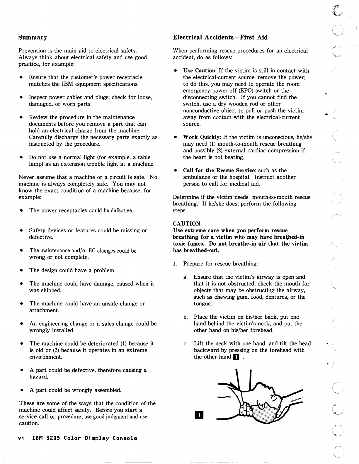
1.
Prepare for rescue breathing:
a. Ensure
b.
c.
care
when you perform rescue
for
a victim who may have breathed-in
Do
not
breathe-in
that
the victim's airway is open and
that
it is not obstructed; check the mouth for
objects
such as chewing gum, food, dentures, or the
tongue.
Place the victim on his/her back, put one
hand behind the victim's neck, and
other hand on his/her forehead.
Lift the neck with one hand, and tilt the head
backward by pressing on the forehead with
the other hand
that
may be obstructing the airway,
0 .
air
that
the
victim
put the
. (
(
/
I
~
that
These are some of the ways
machine could affect safety. Before you
service call
caution.
vi
IBM
or' procedure,
3205
Color
use
Display
the condition of the
good
judgment
Console
start
and
a
use
..
Page 7
c
2.
c
C:
.
..
i
C
j
()
(~'/
{
("
3.
Look, listen, and feel to determine if the victim
breathing freely:
a. Put your cheek near the victim's mouth and
nose.
b.
Listen and feel for the breathing-out of air.
At
the same time,
and upper abdomen to see if they move up
and down.
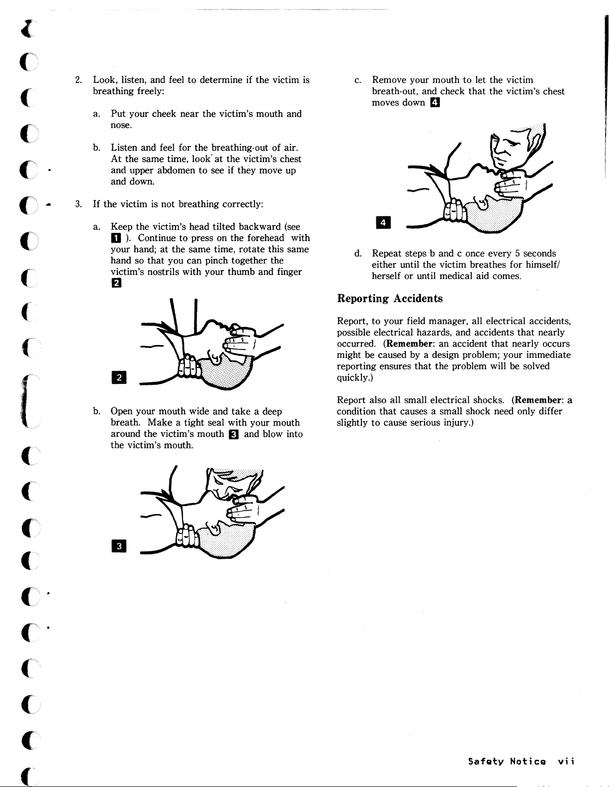
If
the victim is not breathing correctly:
a. Keep the victim's head tilted backward (see
D).
Continue to press on the forehead with
your hand;
hand so
victim's nostrils with your thumb and finger
at
that
look"
at
the victim's chest
the same time, rotate this same
you can pinch together the
B
II
is
c.
Remove your mouth to let the victim
breath-out, and check
moves down
D
that
the victim's chest
II
d.
Repeat steps
either until the victim breathes for himself/
herself or until medical aid comes.
Reporting Accidents
Report, to your field manager, all electrical accidents,
possible electrical hazards, and accidents that nearly
occurred.
might
reporting ensures that the problem will
quickly.)
(Remember: an accident
be caused
band
c once every 5 seconds
that
nearly occurs
by
a design problem; your immediate
be solved
c·
(~i
b.
Open your mouth wide and
breath. Make a tight seal with your mouth
around the victim's mouth
the victim's mouth .
take
a deep
IJ and blow into
•
Report also all small electrical shocks.
condition
slightly to cause serious injury.)
that
causes a small shock need only differ
(Remember: a
Safety
Notice
vii
Page 8

...
viii
IBM
3205
Color
Display
Console
Page 9
(\
Ci
c'
c
().
c
..
PREFACE
The
IBM
units:
during
document
and
basic
another.
This
operation,
repair
understanding
manual
3205
Color
the
video
provides
units
contains
Display
unit,
the
the
at
the
of
Console
logic
customer
information
customer
processors
the
following
unit,
should
site.
is a console
and
keyboard
call
that
and
the
This
display
information:
IBM
IBM
manual
console
terminal
unit.
for
console
customer
assumes
that
If
engineer
and
one
repair
that
their
consists
of
the
service.
needs
the
relationship
of
units
to
reader
three
fails
This
analyze
has
to
a
one
c
C
c:
[
c'
(~
Chapter
Chapter
when a
Chapter
and
Chapter
Chapter
unsafe
designed
operators,
addresses
Appendix
the
Appendix
packing
Related
IBM
IBM
GA18-2339
IBM
IBM
problem
replace
conditions
IBM
3179
3205
4361
4381
1,
"Introduction"
2,
"Problem
occurs.
3,
"Removal
field-replaceable
4,
"3205
5, "IBM
and
and
those
A,
"IBM 3205
3205
B,
"Packing
is
needed.
publications:
Color
Color
Processor
Operations
Part
3205
built,
service
items.
console
Display
Display
on
Determination
and
Replacement
Numbers" on
Safety
on
machines
had
required
personnel
Installation
and
attach
Instructions"
Station
Console
Operating
Manual,
page
1-1
Guide"
units
page
Inspection
that
are
safety
from
Instructions"
it
to
on
Description,
Operator
Procedures,
GA24-3949
gives a general
on
page
Procedures"
CFRUs).
4-1
lists
Guide"
being
items
injury.
the
page
Reference
GA33-1570
on
inspected.
installed
The
processor.
B-1
illustrates
GA18-2177
2-1
on
page
the
page
checklist
on
and
description
contains
3-1
part
5-1
Each
to
page
A-I
Problem
procedures
describes
numbers
identifies
machine,
protect
in
this
describes
procedures
Determination
of
the
how
of
the
potentially
as
the
owners,
chapter
how
to
IBM
3205.
to
follow
to
remove
IBM
3205.
it
was
to
follow
Guide,
setup
when
c
c
c·
c
("j
Preface
ix
Page 10

..
,
\~
...
/
,--j}
x
IBM
3205
Color
Display
Console
Page 11
()
CONTENTS
()
()
()-
()
[
Chapter
1.1
1.2
1.4
1.6
1.7
1.8
1.9
1.3
1.4.1
1.4.2
1.5
Video
Keyboard
Logic
Indicators,
Operator
Offline
Data
122-key
124-Key
Chapter
2.1
2.2
2.3
Console
Symptom
2.2.1
2.2.2
2.2.3
2.2.4
2.2.5
2.2.6
2.2.7
2.2.8
2.2.9
Offline
2.3.1
Chapter
3.1
3.2
3.3
Keyboard
Logic
3.2.1
3.2.2
3.2.3
Video
1.
Introduction
Unit
Unit
Indicators
Switches
Flow
2.
Problem Determination Guide
Operator
Power-On
Display
Keyboard
Audible
Monocase/Dualcase
Color
Pedestal
Security
Offline
3.
Removal
Unit
Logic
Logic
Security
Unit
1-1
Unit
1-1
Switches,
and
Messages
Tests
1-7
Keyboard
Keyboard
Quick
Index
Tests
Check
Messages
Light
Problem
Problem
Alarm
Switch
or
Key
Test
Unit
3-2
Unit
Board
Keylock
3-6
1-!
1-6
2-4
2-29
and Replacement Procedures
3-1
Cover
1-1
1-4
Power
Assembly
and
Controls
(LINE
(Keyboard-To-Display
(Keyboard-To-Display
or
Problem
Problem
Problem
Procedure
25)
2-2
2-6
Status
2-11
2-21
Switch
Cord
3-2
Assembly
Controls
1-4
1-5
Light
2-24
Problem
2-27
Problem
2-28
2-31
3-4
3-5
1-4
Test)
Test)
2-1
Problem
2-26
2-28
1-8
1-9
2-8
3-1
"'i
(
, /
C~
c··
c·
c
-.,
(
j
c\
Chapter
Chapter
5.1
5.2
5.3
5.4
5.5
5.6
5.7
5.8
Preparation
General
General
Video
Low
High
Keyboard
Keyboard
APpendix
A.!
A.2
A.3
A.4
A.5
A.6
A.7
A.S
A.9
Set
Attach
Attach
Connect
Attach
Set
Adjust
Check
Personalize
Appendix
B.l
Video
B.2
Keyboard
B.3
B.4
Logic
Three
4.
3205
5.
IBM
Unit
Voltage
Voltage
A.
Switches
Pedestal
Pedestal
Cable
Power
the
Audible
B.
Unit
Unit
Units
Part
3205
5-2
Guidelines
5-3
5-4
5-5
5-5
Unit
Unit
IBM
Cables
(Membrane
(Capacitance
3205
On
to
Clamp
On
A-9
Brightness
Alarm
the
Packing
B-1
Unit
B-1
B-2
In A Master
Numbers
Safety
5-2
4-1
Inspection
type)
Installation
the
Underside
to
Logic
to
Video
the
A-S
Console
Rear
of
A-II
Unit
Unit
Your
for
Instructions
Carton
Guide
5-6
type)
5-7
Instructions
of
the
A-3
A-5
A-7
Display
the
Operator
B-1
B-2
5-1
Keyboard
A-IO
A-12
A-I
A-2
(
Contents
xi
Page 12

...
(
(
\
"
(
(
c
xii
IBM
320S
Color
Display
c
Console
Page 13
(~::
C
()
()
()
c
..
c
(
c·
'"
.
(
'--'
c
c
FIGURES
1-1.
1-2.
1-3.
1-4.
1-5.
1-6.
1-7.
2-1.
2-2.
2-3.
2-4.
2-5.
2-6.
2-7.
2-8.
2-9.
2-10.
2-11.
2-12.
2-13.
2-14.
2-15.
2-16.
2-17
.
2-18.
2-19.
2-20.
2-21.
2-22.
2-23.
2-24.
2-25.
2-26.
2-27.
2-28.
2-29.
2-30.
2-31.
2-32.
2-33.
2-34.
2-35.
2-36.
2-37.
2-38.
2-39.
2-40.
2-41.
2-42.
2-43.
2-44.
2-45.
3-1.
3-2.
3-3.
4-1.
4-2.
5-1.
5-2.
5-3.
5-4.
5-5.
A-I.
A-2.
A-3.
A-4.
A-S.
A-6.
Console
IBM
Setup
Offline
IBM
Keyboard-to-display
Keyboard-to-display
Keyboard
Keyboard
Video
Pin
Display
Display
Display
Display
Display
Display
Status
Status
Status
Test/Normal
Video
Status
Video
Status
Test/Normal
Without-Cursor
All
Status
Some
Automatic
Double
Different
Setup
Audible
No
Video
Audible
Monocase/Dualcase
Color
Pedestal
Power Cord
Security
Offline
Switches
All-character
All-character
7-color
4-color
2-color
Setup
Characters
Logic
Logic
Security
IBM
Logic
Video
Grounding
Grounding
Keyboard
Keyboard
Console
Turn Keyboard A-2
Setup
Set
Lock
Ensure
Units,
3205
3205
Voltages
Characters
Alarm
3205
Pedestal
1-3
Switches
Test
Data
Cable
Cable
Cable
A
2-11
B
2-11
C
2-12
D
2-12
E
2-12
F
2-13
Light
Light
Light
Cable
Cable
Character~
Switches
Cable
(00/0000)
Switches
Unit
Board
Unit
Unit
Switches
Gray
Switch
Light
Light
Switch
Light
Characters
Characters
Characters
Alarm
2-24
Alarm
2-28
2-28
Key
Test
Setting
Pattern
Pattern
Pattern
displayed
Cover
Assembly
Keylock Assembly
Final
4-5
5-4
Pass
Pass
Unit
Unit
and
Parts
Latches
Lock A-4
Accessories
1-5
Pattern
Flow
2-6
2-7
2-8
in
Video
2-13
2-14
2-15
2-17
2-17
2-18
2-18
Character
2-21
2-21
2-23
2-24
2-25
Control
Switch
Failure
Pattern
Pattern
Pattern
and
Assembly
Schematics
Schematics
(Membrane
(Capacitance
A-2
A-3
1-7
test
test
2-16
2-19
2-22
2-22
(A/A,a)
2-31
2-34
2-34
2-34
Jumpers
in
3-3
A-I
A-3
and
1-6
(I22-key
(124-key
Cable
2-22
2-23
Knob
2-27
2-28
2-30
in
in
3-4
2-10
2-20
2-25
Switch
Dualcase
Monocase (A)
Status
the
Keyboard-to-disp1ay
3-5
4-1
5-5
5-5
type)
type)
Parts
keyboard)
Katakana
2-26
(A,a)
2-35
5-6
5-7
1-2
2-33
1-8
keyboard)
2-32
test
1-9
2-37
{
..
---
..
----
..
--~~~~=
--.-.'---""'"
Figures
.-
.... --
-.~-~
-~-~---
....
-.-
....
------~
xiii
Page 14
A-7.
A-S.
A-9.
A-lO.
A-ll.
A-12.
A-13.
A-14.
A-IS.
A-16.
A-17
A-IS.
A-19.
A-20.
A-2l.
A-22.
A-23.
A-24.
A-2S.
A-26.
A-27.
A-2S.
B-1.
B-2.
B-3.
B-4.
Turn
Hook
Turn Video
Connect
Keyboard
Connect
Prepare
Close
Attach
Unlock
•
Power
Plug
Power on A-9
Set
Adjust
Color
Check
Adjust
Set
Position
Adjust
Store
Packing
Packing
Packing
Packing
Video
Pedestal
Cable
off
in
Switches
Test
Audible
Test/Normal
Manual
Unit
to
Unit
Video
Cable
Power
Cable
Cable
Security
Power
Brightness
Audible
the
Keyboard
Video
Keyboard
Logic
Three
Cable
Cord
Clamp
Clamp A-a
Clamp A-S
A-9
Cord
A-lO
Pattern
Alarm
console
into
Unit
Unit
Units
A-S
Video
A-6
A-7
Key
Control
Alarm
Switch
Angle
Pocket
Unit
Unit
A-7
A-7
A-S
A-9
A-9
A-lO
A-II
A-II
A-12
A-12
B-1
B-1
B-2
B-2
A-S
c
A-IO
A-II
A-13
xiv
IBM
320S
Color
Display
(
(f'"
'L.:J
()
Console
Page 15
"'.
(
, "
CO)
()
().
().
c
CHAPTER
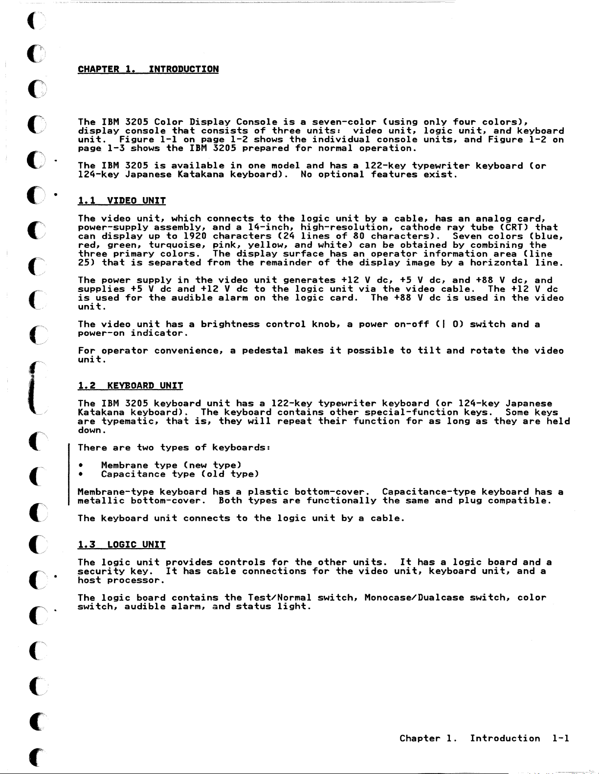
The
display
unit.
page
The
124-key
1.1
The
power-supply
can
red,
three
25)
The power
supplies
is
used
unit.
The
power-on
For
unit.
1.
IBM
3205
console
Figure
1-3
shows
IBM
3205
Japanese
VIDEO
video
display
green,
primary
that
is
+5 V dc
for
video
operator
indicator.
INTRODUCTION
Color
is
that
I-Ion
the
available
Katakana
Display
IBM
UNIT
unit,
supply
unit
which
assembly,
up
to
turquoise,
separated
the
convenience,
1920
colors.
in
the
and
audible
has a brightness
consists
page
+12 V
Console
of
1-2
3205
connects
and a 14-inch,
characters
pink,
The
from
video
alarm
shows
prepared
in
one
keyboard).
yellow,
display
the
unit
dc
to
on
a
pedestal
is a seven-color
three
model
to
remainder
the
the
control
units:
the
individual
for
and
No
the
logic
high-resolution,
(24
lines
and
surface
generates
logic
logic
knob,
makes
video
normal
has a 122-key
optional
white)
has
of
unit
card.
it
operation.
unit
of
80
can
an
the
display
+12 V
via
a power
possible
features
by a cable,
characters).
operator
The +88 V
(using
unit,
console
cathode
be
obtained
image
dc,
+5 V
the
video
on-off
to
only
four
logic
units,
typewriter
exist.
has
ray
Seven
by
information
by a horizontal
dc,
and
cable.
dc
is
(I
0)
tilt
and
colors),
unit,
and
Figure
keyboard
an
analog
tube
colors
combining
+88 V
The +12 V
used
switch
rotate
and
(CRT)
area
in
keyboard
1-2
(or
card,
that
(blue,
the
(line
line.
dc,
and
the
video
and
a
the
video
on
dc
[
C:
c:'
1.2
The
Katakana
are
down.
There
•
Membrane-type
metallic
The
1.3
The
security
host
The
switch,
KEYBOARD
IBM
typematic,
Membrane
•
Capacitance
keyboard
LOGIC
logic
processor.
logic
3205
keyboard).
are
two
bottom-cover.
UNIT
unit
key.
board
audible
UNIT
keyboard
that
types
type
(new
type
keyboard
unit
connects
provides
It
has
contains
alarm,
unit
The
is,
of
(old
has a 122-key
keyboard
they
keyboards:
type)
type)
has a plastic
Both
to
controls
cable
the
and
status
the
contains
repeat
are
logic
for
light.
will
types
connections
Test/Normal
typewriter
other
their
bottom-cover.
functionally
unit
the
other
for
switch,
function
by a cable.
units.
the
keyboard
special-function
Capacitance-type
the
same
video
Monocase/Dualcase
It
unit,
(or
for
as
and
has a logic
keyboard
124-key
keys.
long
plug
as
they
keyboard
compatible.
board
unit,
switch,
Japanese
Some
keys
are
has
and
and
color
a
held
a
a
Chapter
1.
Introduction
1-1
Page 16
Monocase/Dualcase
(A/A,a)
Switch
Video
Cl
Unit
Brightness
Control Knob
C
'
/
j'
Color
(00/0000)
Status Light
Test/Normal
Switch
Switch
Keyboard
Unit
/~
Cable Clamp
On/Off
Switch
Power-On
Light
Logic
;-;:F;;~~---
Security Key
Unit
(I
0)
Audible Alarm
Volume Control
Knob
3205 MIM
(
".
')
./
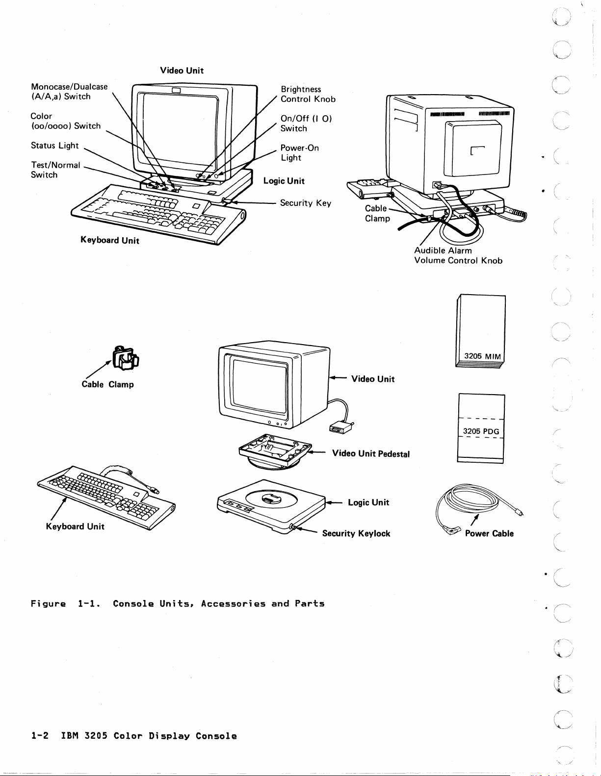
Figure
1-1.
Console
Units,
~
Accessories
and
Security Keylock
Parts
1------
3205
PDG
1-----
V"'oUn~Ped.""
Logic
Unit
Power Cable
(
\.
1-2
IBM
3205
Color
Display
c
Console
Page 17

{~
(~
('
(~
(
\
(:
(
(~
(
(/
.
('
.
{
(.~
(
1-
2
.
Page 18
o
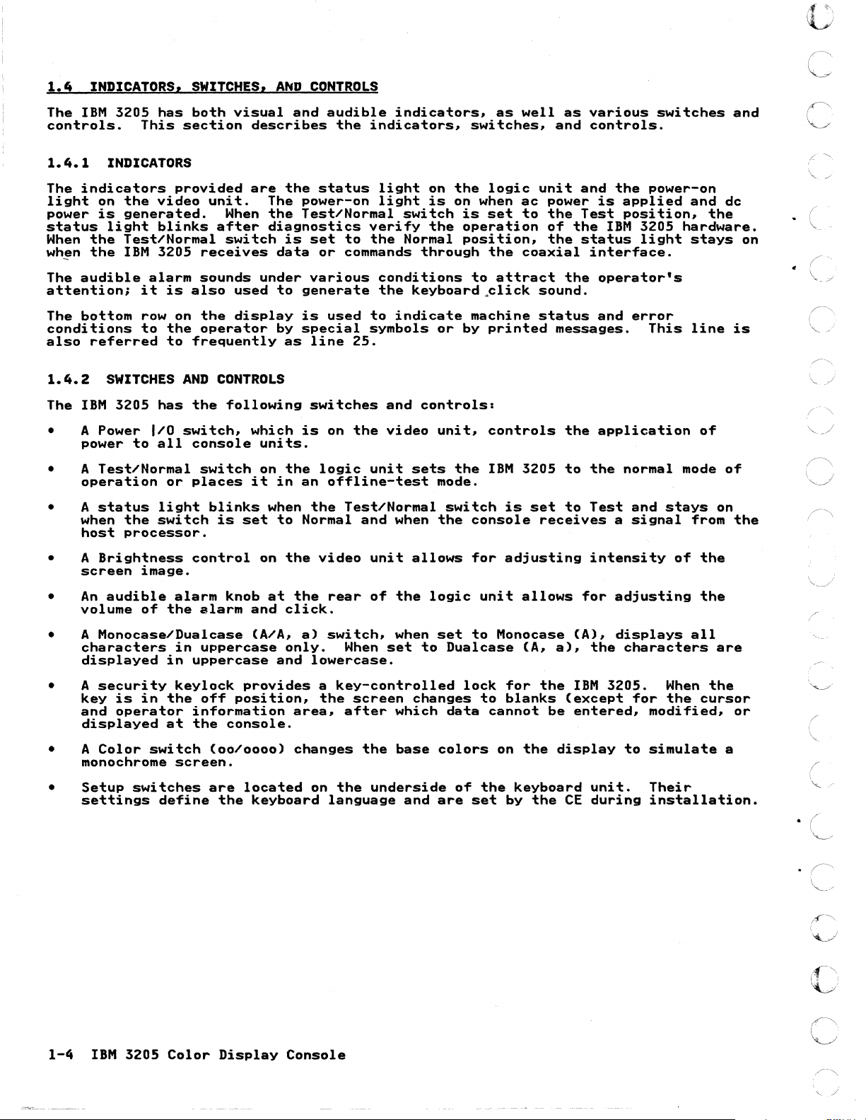
1.4.1
The
light
power
status
When
wh~n
The
attention;
The
conditions
also
1.4.2
The
•
•
•
• A
INDICATORS
indicators
on
is
light
the
the
audible
bottom
referred
SWITCHES
IBM
A Power
power
A
Test/Normal
operation
A
status
when
host
Brightness
screen
the
generated.
Test/Normal
IBM
provided
video
blinks
3205
alarm
it
is
row on
to
the
to
AND
3205
has
I/O
to
the
processor.
switch#
all
or
light
switch
image.
are
unit.
When
after
switch
receives
sounds
also
frequently
used
the
display
operator
CONTROLS
the
following
blinks
is
set
which
it
console
switch
places
control
the
The
the
diagnostics
under
units.
on
when
on
status
power-on
Test/Normal
is
set
data
to
generate
is
by
special
as
is
the
in
an
to
Normal
the
or
various
line
switches
logic
the
video
light
light
verify
to
the
commands
conditions
the
used
to
indicate
symbols
25.
and
on
the
video
unit
offline-test
Test/Normal
and
when
unit
on
the
is
switch
the
Normal
through
keyboard~lick
or
controls:
unit#
sets
mode.
switch
the
allows
logic
on when
is
set
operation
position,
the
to
attract
machine
by
printed
controls
the
IBM
is
console
for
adjusting
ac
to
coaxial
3205
unit
power
the
of
the
the
sound.
status
messages.
the
to
set
to
receives
and
the
is
Test
the
IBM
status
interface.
operator's
and
application
the
Test
a
intensity
power-on
applied
position#
3205
light
error
This
normal
and
stays
signal
of
and
dc
the
hardware.
stays
line
of
mode
from
the
on
is
of
on
the
An
•
volume
• A
characters
displayed
A
•
key
and
displayed
A
•
monochrome
Setup
•
settings
audible
Monocase/Dualcase
security
is
operator
Color
alarm
of
the
in
in
keylock
in
the
at
switch
screen.
switches
define
knob
alarm
uppercase
uppercase
off
information
the
console.
(00/0000)
are
the
at
the
rear
of
and
click.
(A/A#
provides a key-controlled
position,
located
keyboard
a)
only.
and
area,
changes
switch,
When
lowercase.
the
after
on
the
language
the
when
set
screen
which
the
base
underside
and
logic
set
to
Dualcase
changes
data
colors
of
are
unit
allows
to
Monocase (A)#
(A#
lock
for
to
blanks
cannot
on
the
the
set
keyboard
by
the
be
the
for
a),
the
IBM
(except
entered#
display
unit.
CE
during
adjusting
displays
characters
3205.
for
modified#
to
simulate
Their
installation.
all
When
the
the
are
the
cursor
or
(
a
(
"'-
. (
"'--/
1-4
IBM
3205
Color
Display
c
Console
Page 19
c
,.,~.,
..
,
...
-.
-,-_
..
_ ....
_--
-------------
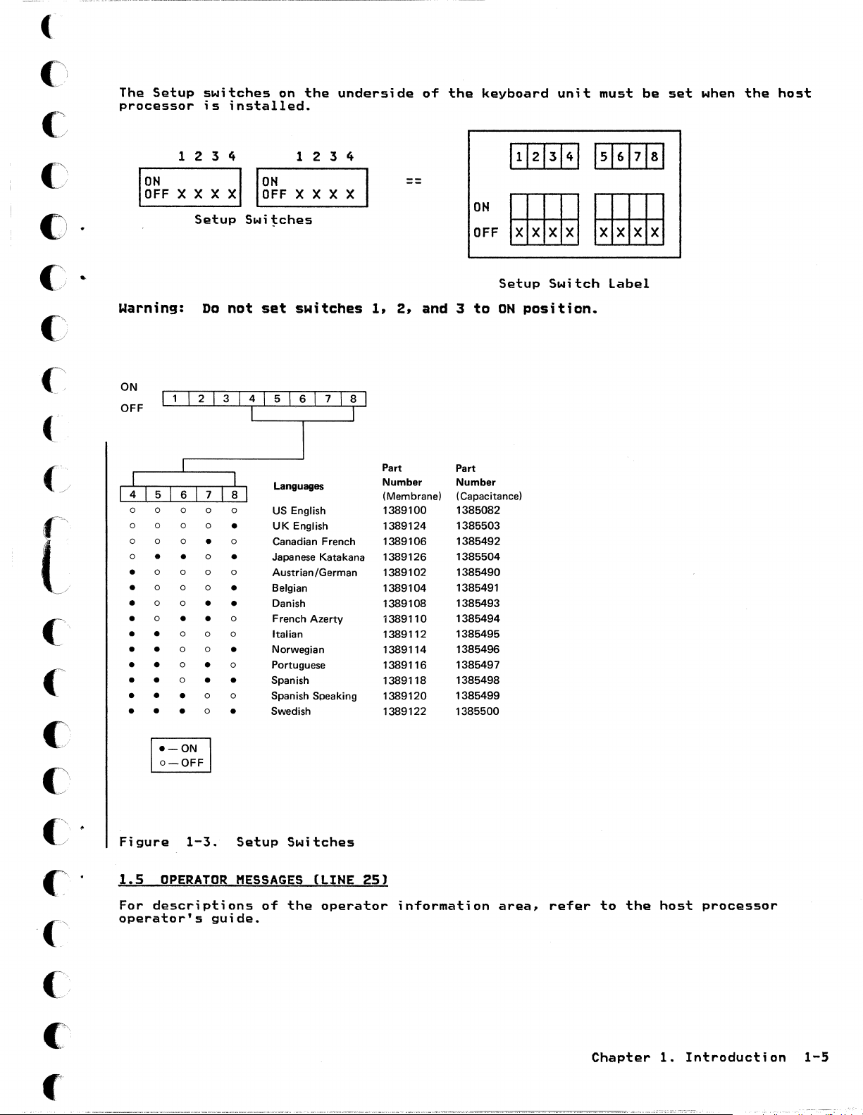
The
Setup
processor
Ig~F
switches
is
1
234
X X X
Setup
on
the
installed.
1
xl
Ig~F
X X X X
Swi~ches
underside
234
of
the
keyboard
ON
OFF
unit
must
be
set
when
the
host
c
c
(>
[
c'
Warning:
ON
OFF
0
0 0
0 0 0
0
0 0
0
0
•
0 0
•
0 0 0
•
0 0
•
0
•
•
•
•
•
•
•
•
•
•
•
•
•
Do
•
• •
0
0 0
0
0
•
•
0
0
0
•
0
•
•
0
0
•
not
0
•
0
•
0
•
•
0
0
•
0
•
0
•
set
switches
Languages
US
English
UK English
Canadian French
Japanese Katakana
Austrian
IGerman
Belgian
Danish
French Azerty
Italian
Norwegian
Portuguese
Spanish
Spanish Speaking
Swedish
1,
2,
Part
Number
(Membrane)
1389100
1389124
1389106
1389126
1389102
1389104
1389108
1389110
1389112
1389114
1389116
1389118
1389120
1389122
and 3
Part
Number
( Capacitance)
1385082
1385503
1385492
1385504
1385490
1385491
1385493
1385494
1385495
1385496
1385497
1385498
1385499
1385500
to
Setup
ON
position.
Switch
label
C
, .
'
a-OFF
~
Figure
1.5
OPERATOR
For
descriptions
operator's
1-3.
Setup
MESSAGES
guide.
Switches
of
the
(LINE
operator
25)
information
area,
refer
to
the
Chapter
host
processor
1.
Introduction
1-5
Page 20
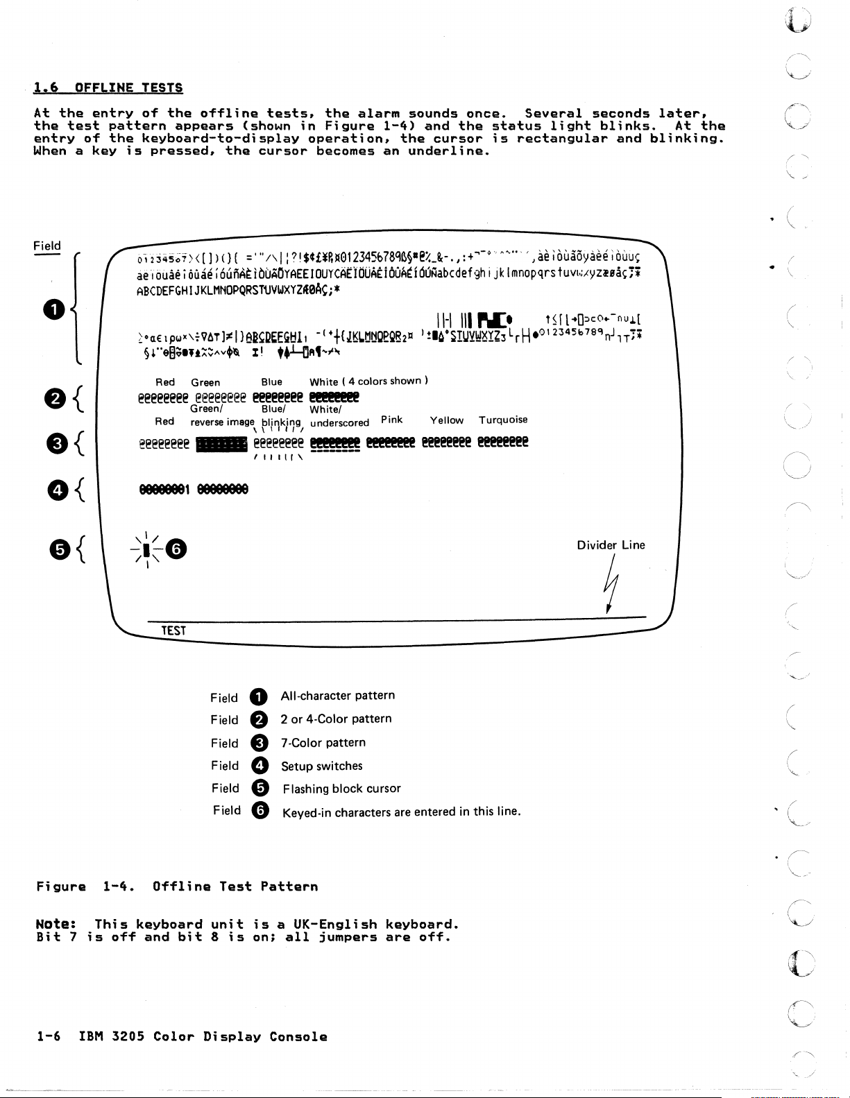
1.6
At
the
entry
When a key
OFFLINE
the
entry
test
of
pattern
the
TESTS
of
the
offline
appears
keyboard-to-display
is
pressed.
the
tests,
(shown
cursor
the
in
Figure
operation.
becomes
alarm
1-4)
an
sounds
and
the
cursor
underline.
once.
the
Several
status
is
rectangular
light
seconds
blinks.
and
later,
At
blinking.
the
.
, ,
({)
(,-"
0
()
;'
'-.
i
7
'"
(
Field
o
e{
e{
e{
e{
0',2
3<i5~i>
<
[1)
()
{
='"
/\
I :?!
$¢£¥R1I012345b78q~§·e%_8c-.,:
ae:,ouae i DUae;
ABCDEFGHIJKLMHOPQRST~VWXyz~aA~i*
~OCl€
lpwx\~VllTl;l!
§r·e8;llt::::~"v.'&
Red Green Blue White ( 4 colors
eee@eee@
Red reverse image,
eeeeeeee
aBBBBBB1
6ui'IAEibbAOYAEEIOUYCAEljjOAE:iOOA~i6UNabcdef9h
I
}ei~D~EG!:!l
II
eeeeeeee
Green!
_
@@!@@@@@
eeeeeeee
, I I I
Blue!
pli~ki7gl
I -
(++{J~L.tltlQ~QB211
ttLrl"t",.
II
..
@!!!!!!(
White!
underscored Pink Yellow Turquoise
!!ft!t!!
,
!I!@I!@I!@@
I
shown)
I!@@I!@@@@
aBBBBBBe
+
...
-0
...........
i
jk
Imnopqrs
11-1
III
PL'
!.~oSIUYI!!~rZ3
L
rH
I!@I!@@@@@
TEST
, J
ae;
ouaoyaee;
tuvl~,(yzlBa~;*
Hfl"O::lco
.01
2345b
OUU~
..
-nu.L[
7SQo-l1T;*
Divider Line
1
•
(
"-
(
\
(
\
'.
( "
i
''-..
(\
\,--,)
/"...
..\
I
Figure
Nate:
Bit 7 is
1-6
IBM
1-4.
This
off
3205
Offline
keyboard
and
bit
Color
Field
Field
Field
Field
Field
Field
Test
unit
8
is
Display
All-character pattern
0
2
or
e
e
0
e
e
Pattern
is a UK-English
on;
4-Color pattern
7 -Color pattern
Setup switches
Flashing block cursor
Keyed-in characters
all
jumpers
Console
are
entered in this line.
keyboard.
are
off.
, (
(
;'
"'-/
I'
C
"
Page 21
(
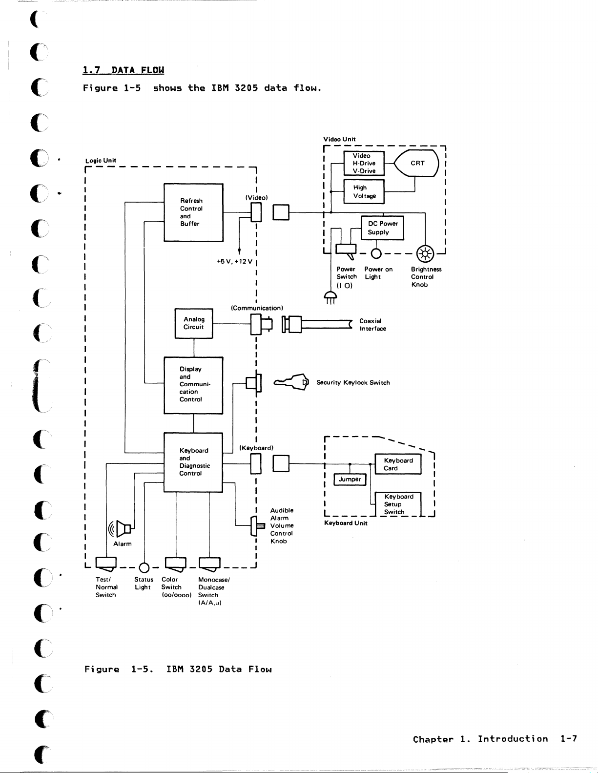
1.7
DATA
FLOW
c
'.
c
()
()
C:
c
[
•
Figure
Logic
Unit
r---
1-5
shows
the
-------..,
Refresh
Control
and
Buffer
Analog
Circuit
Display
and
Communi-
cation
Control
IBM
3205
+5V,+12V
(Communication)
I
I
(Video)
I
I
I
I
I
data
Ilf"I
ULJr-----
~
flow.
Video
Security Keylock Switch
Unit
Power
Light
( Coaxial
...
- Interface
on
Brightness
Control
Knob
c\
('
c
'""
I
(
./
c
Alarm
L
Test/ Status
Normal
Switch
Figure
Light
1-5.
Color
Switch
(00/0000)
IBM
Keyboard
and
Diagnostic
Control
Monocase/
Dualcase
Switch
(A/A,a)
3205
___
Data
(Keyboard)
I
I
I
..J
Flow
Audible
Alarm
Volume
Control
Knob
r------
I
I ..,
Keyboard
Unit
--_
I
I
I
I
I
.J
Chapter
1.
Introduction
1-7
Page 22
o
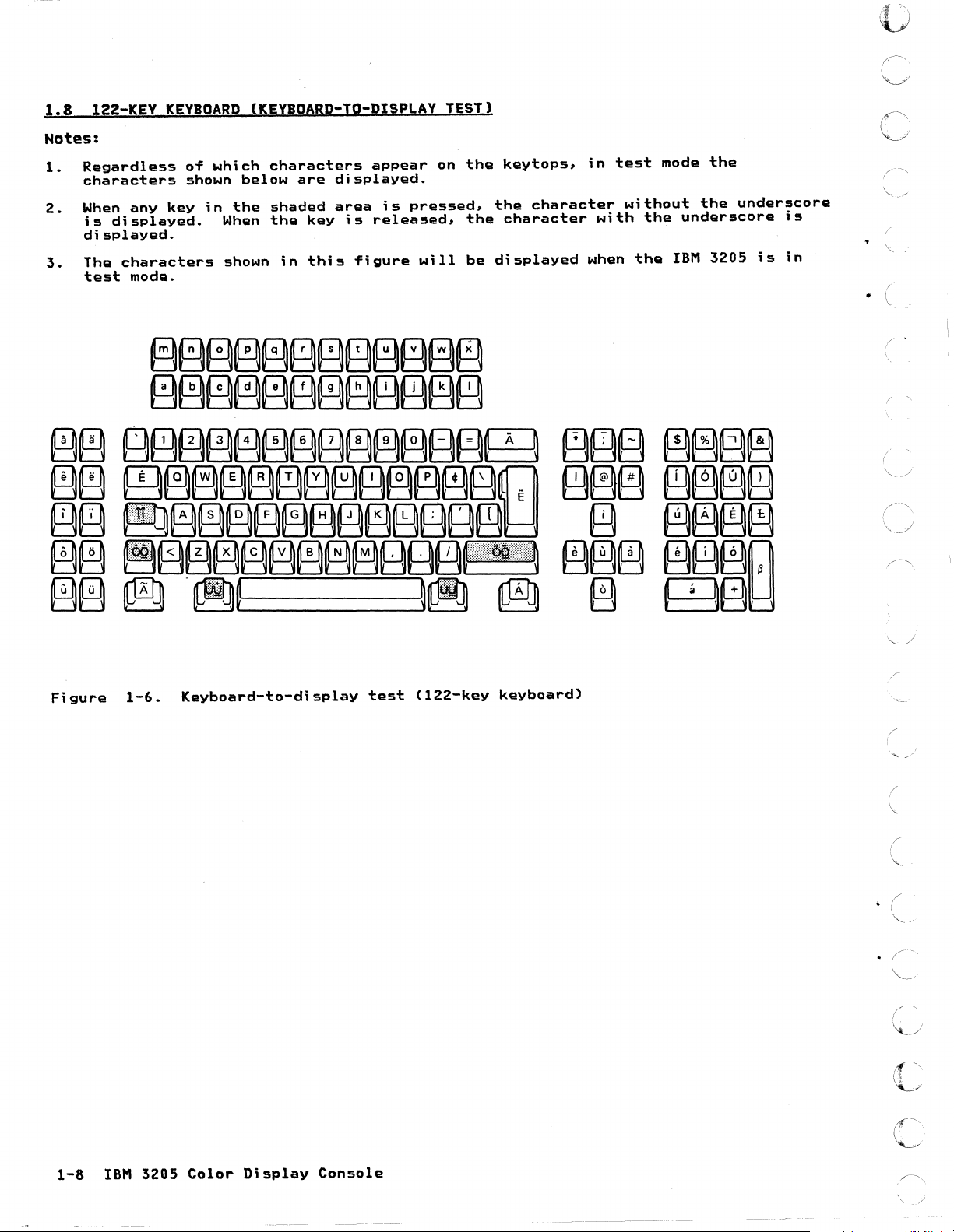
1.8
Notes:
Regardless
1.
characters
When
2.
is
displayed.
The
3.
test
122-KEY
any
displayed.
characters
mode.
KEYBOARD
of
shown
key
(KEYBOARD-TO-DISPLAY
which
below
in
the
When
shown
characters
are
shaded
the
key
in
this
appear
displayed.
area
is
figure
is
released.
TEST)
on
pressed.
will
the
the
be
key
tops,
the
characte~
character
displayed
in
w1th
when
test
without
the
the
mode
the
underscore
IBM
the
under~core
3205
is
15
in
(~\
\ '
o
Figure
1-6.
Keyboard-to-display
test
(122-key
keyboard)
\"
/"
(
(
\.-
(
. (
"'-
..
./
..
c
1-8
IBM
3205
Color
Display
Console
·
C
-
\_/
__
'.
-I
Page 23
(-
("
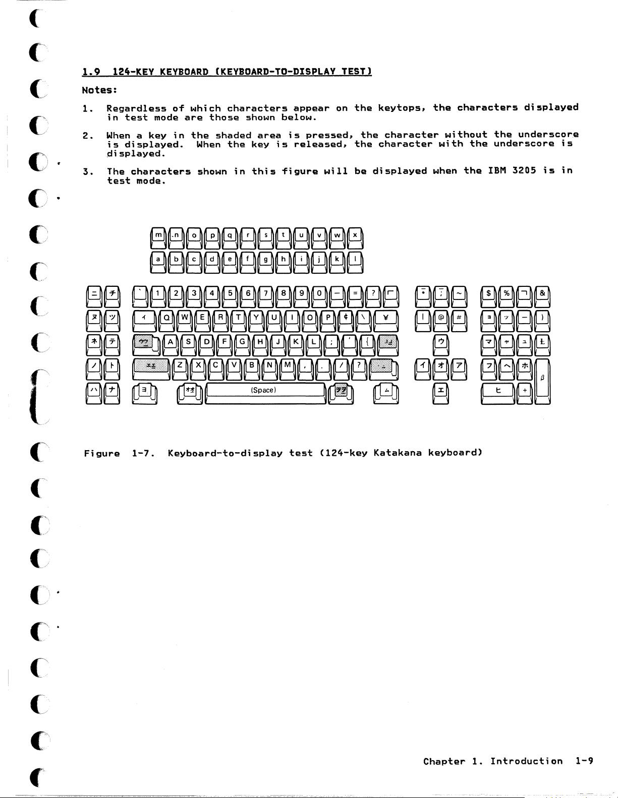
1.9
124-KEY
KEYBOARD
(KEYBOARD-TO-DISPLAY
TEST)
C
().
c·
c
Notes:
1.
Regardless
in
2.
When a key
is
displayed.
3.
The
test
test
mode
displayed.
characters
mode.
of
in
which
are
the
When
shown
characters
those
shaded
the
in
shown
area
key
this
appear
below.
is
is
released,
figure
on
pressed,
will
the
the
the
be
displayed
key
tops,
character
character
the
without
with
when
characters
the
the
underscore
the
IBM
displayed
underscore
3205
is
is
in
(
4[~
>,
(
/
(~
(~.
C
Figure
1-7.
Keyboard-to-display
test
(124-key
Katakana
keyboard)
Chapter
1.
Introduction
1-9
Page 24

· (
1-10
IBM
3205
Color
Display
Cons.o1e
,
(
_/
~i
I
I
Page 25

(
("\
(-
(',
/'
()
•
C)
C
(,~
(
(~
CHAPTER
This
processor
The
•
•
•
When
which
directs
After
If
instructions.
2.
chapter
chapter
Console
Symptom
Individual
you
subdivides
you
replacing
no
trouble
PROBLEM
describes
console.
is
Quick
Index
suspect
to
is
DETERMINATION
the
arranged
Check
Tests
console
the
a Symptom
any
found.
into 3 parts:
based
problems,
problem
Index
field
return
GUiDE
procedures
on
the
symptom
into
categories
from
replaceable
to
the
for
start
which
unit
processor
analyzing
with
(such
has
(FRU),
the
you
and
Console
as
perform
perform
problem
repairing
Quick
power.
individual
the
analysis
problems
Check.
display,
Console
guide
This
keyboard)
tests.
Quick
for
further
in
the
check.
Check.
i,
/
r
("\
(
C
'/
Ci
.
\
C
0
C'
C
C'
C"
Chapter
2.
Problem
Determination
Guide
2-1
Page 26
o
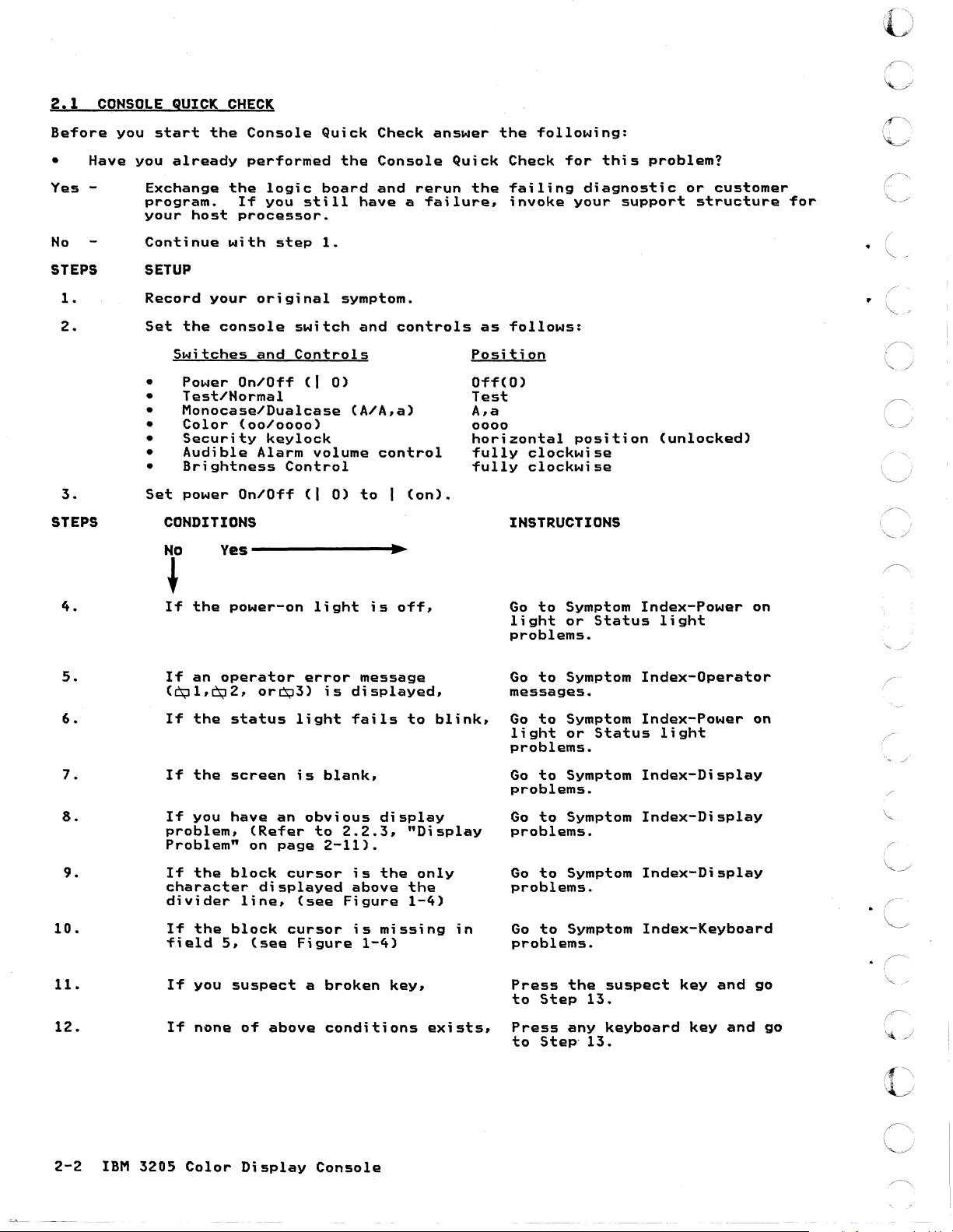
2.1
Before
• Have
Yes
No
CONSOLE
you
-
STEPS
1-
2.
3.
STEPS
QUICK
start
you
alreadY
Exchange
program.
your
Continue
host
SETUP
Record
Set
the
Switches
Power
•
Test/Normal
•
Monocase/Dualcase
•
Color
•
Security
•
Audible
•
Brightness
•
Set
power
CONDITIONS
No
CHECK
the
Console
performed
the
If
processor.
with
your
console
On/Off
(00/0000)
On/Off
logic
you
original
and
keylock
Alarm
still
step
switch
Controls
(I
volume
Control
(I
Quick
board
1.
0)
0)
Check
the
Console
and
have a failure,
symptom.
and
(A/A,a)
control
to 1 (on).
answer
rerun
controls
the
Quick
the
as
Position
Off(O)
Test
A.a
0000
horizontal
fully
fully
Check
failing
invoke
follows:
INSTRUCTIONS
yes--------------~.~
following:
for
diagnostic
your
position
clockwise
clockwise
this
support
problem?
or
structure
(unlocked)
customer
for
..
( ,
/'
I
~.
/""\
''=.
./
4.
5.
6.
7.
3.
9.
10.
11.
12.
~
If
the
pOwer-on
If
an
the
the
you
the
the
you
none
operator
status
screen
have
block
block
5.
suspect
(0;11, ~ 2.
If
If
If
problem.
Problem"
If
character
divider
If
field
If
If
orCs;l3)
an
(Refer
on
page
displayed
line.
(see
of
above
light
error
is
light
is
blank,
obvious
to
2-11).
cursor
(see
cursor
Figure
a
broken
conditions
is
message
di
splayed.
fails
display
2.2.3,
is
the
above
Figure
is
missing
1-4)
off.
to
"Display
only
the
1-4)
key,
exists,
blink,
in
Go
to
light
problems.
Go
messages.
Go
light
problems.
Go
problems.
Go
problems.
Go
problems.
Go
problems.
Press
to
Press
to
Symptom
or
to
Symptom
to
Symptom
or
to
Symptom
to
Symptom
to
to
Step
Step'
Symptom
Symptom
the
any
Status
Status
suspect
13.
keyboard
13.
Index-Power
light
Index-Operator
Index-Power
light
Index-Display
Index-Display
Index-Display
Index-Keyboard
key
and
key
and
on
on
/"
go
go
2-2
IBM
3205
Color
Display
Console
Page 27
(-
(~
(
C'
£)
C
C
C\
/
(~-
('"
•
•
STEPS
13.
14.
15.
16.
17.
CONDITIONS
If
the
displayed,
If
display,
If
appear
page
If
If
exist.
block
the
normal
all
the
correct.
2-37>.
incorrect
none
of
cursor
cursor
characters
(See
characters
conditions
is
still
fail
in a line
Figure
appear,
1
through
to
2-45
INSTRUCTIONS
Go
Problems.
Go
problems.
Go
on
page
Go
problems.
16
Go
page.
to
Symptom
to
Symptom
to
2.3.
2-29.
to
Symptom
to
Symptom
Index-Keyboard
Index-Keyboard
"Offline
Index-Keyboard
Index
Tests"
on
next
on
[
(~'
C
C
C'
·
C:/
·
C~
C
("
.~
..
'
C
£
Chapter
2.
Problem
Determination
Guide
2-3
Page 28
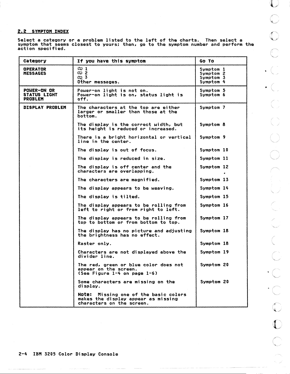
2.2
IIMPTOM
Select
symptom
action
Category
OPERATOR
MESSAGES
POWER-ON
STATUS
PROBLEM
INDEX
a
category
that
specified.
seems
OR
LIGHT
or a problem
closest
If
Cs;J1
13;12
~3
Other
Power-on
Power-on
off.
to
you
have
messages.
listed
yours;
this
light
light
to
then,
symptom
is
not
is
on,
the
left
go
to
on.
status
of
the
the
light
charts.
symptom number
is
Then
and
Go
To
Symptom
Symptom
Symptom
Symptom
Symptom
Symptom
select
perform
1
2
3
4
5
6
".'1 . \\
'0'
,~
\.1....
• I
a
the
0'
c
. (
DISPLAY
PROBLEM
The
characters
larger
bottom.
The
its
There
line
The
The
The
characters
The
The
The
The
left
The
top
The
the
Raster
or
display
height
is a bright
in
display
display
display
characters
display
display
display
to
display
to
bottom
display
brightness
only.
smaller
is
the
are
right
at
the
than
is
the
reduced
center.
is
is
is
appears
is
appears
appears
has
horizontal
out
reduced
off
overlapping.
are
tilted.
or
from
or
from
no
has
top
are
those
correct
or
of
focus.
center
magnified.
to
to
to
picture
no
width,
increased.
in
size.
and
be
weaving.
be
rolling
right
be
rolling
bottom
and
effect.
either
at
or
the
to
left.
to
adjusting
the
but
vertical
from
from
top.
Symptom 7
Symptom
Symptom
Symptom
Symptom
Symptom
Symptom
Symptom
Symptom
Symptom
Symptom
Symptom
Symptom
8
9
10
11
12
.
13
14
15
16
17
18
18
('
\.
(~
,
"
/
2-4
IBM
3205
Color
Characters
divider
The
red,
appear
(See
Some
display.
Figure
characters
Nate:
makes
characters
Display
the
are
line.
green
on
the
1-4
Missing
display
on
Console
not
displayed
or
blue
screen.
on
page
are
one
of
appear
the
screen.
color
1-6)
missing
the
as
above
does
on
basic
missing
not
the
colors
the
Symptom
Symptom
Symptom 20
19
20
()
('
~._./
Page 29
category
If
you
have
this
symptom
Go
To
(~
c·
(~,
c
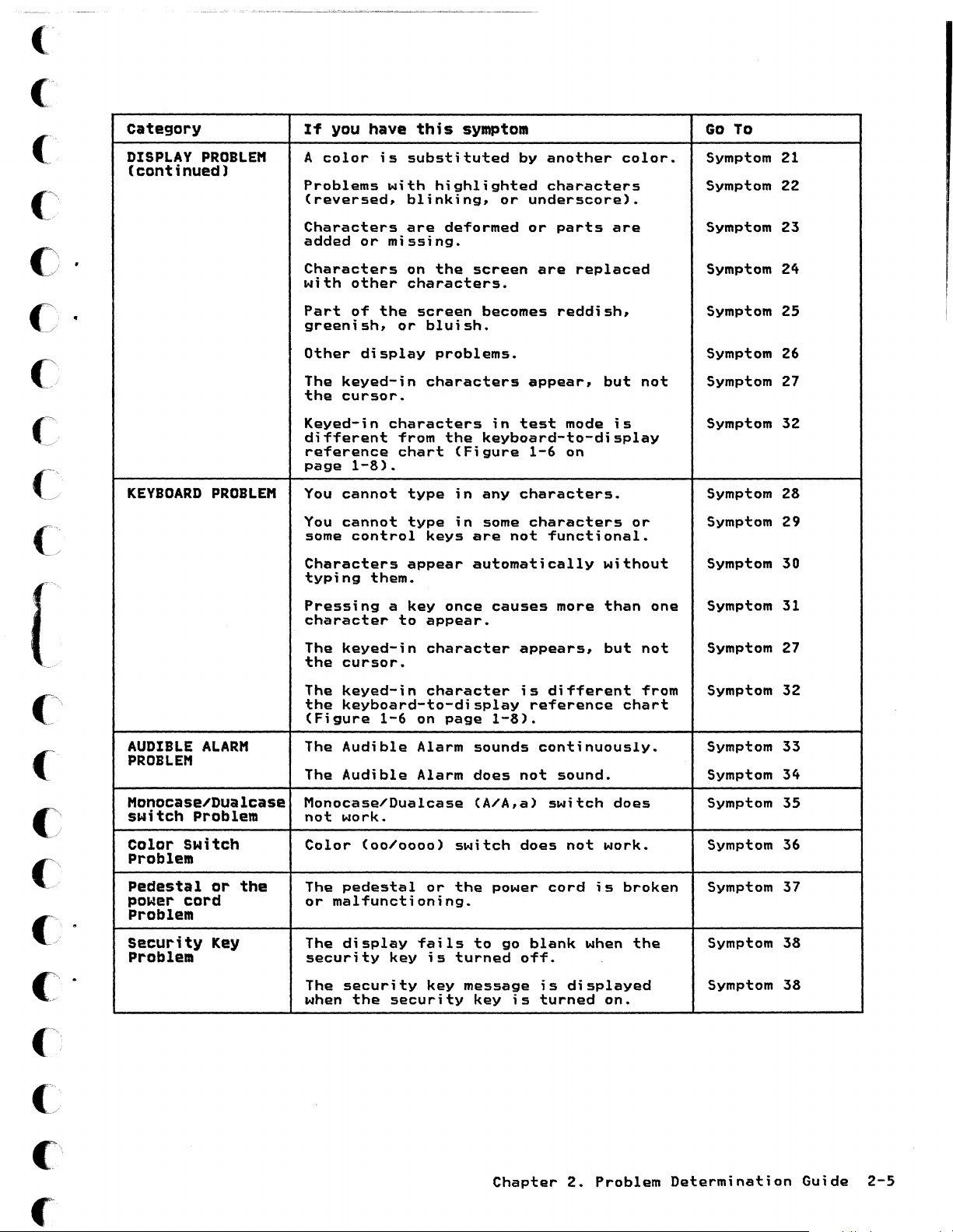
DISPLAY
(continued)
KEYBOARD
PROBLE"
PROBLE"
color
A
Problems
(reversed.
Characters
added
Characters
with
Part
greenish.
other
The
the
Keyed-in
different
reference
page
You
You
some
Characters
typing
Pressing
character
or
other
of
display
keyed-in
cursor.
1-8).
cannot
cannot
control
them.
is
substituted
with
the
highlighted
blinking.
are
missing.
on
the
characters.
screen
or
bluish.
problems.
characters
characters
from
chart
type
type
keys
appear
a
key
to
appear.
by
another
or
deformed
screen
becomes
the
once
in
keyboard-to-display
(Figure
in
any
in
some
are
automatically
causes
characters
underscore).
or
are
appear,
test
1-6
characters.
characters
not
functional.
parts
replaced
reddish.
but
mode
on
without
more
than
color.
are
is
or
not
one
Symptom 21
Symptom 22
Symptom 23
Symptom 24
Symptom 25
Symptom
Symptom 27
Symptom 32
Symptom 28
Symptom 29
Symptom
Symptom 31
26
30
{
c
C
-'
(
" .
j
c·
(~;
AUDIBLE
PROBLE"
"onocasel'Dualcase
switch
Color
Problem
Pedestal
power
Problem
security
Problem
ALAR"
Problem
switch
01"
cord
the
Key The
The
keyed-in
the
cursor.
The
keyed-in
the
keyboard-to-display
(Figure
The
Audible
The
Audible
Monocasel'Dualcase
not
work.
Color
The
or
security
The
when
(00/0000)
pedestal
malfunctioning.
display
security
the
1-6
on
Alarm
Alarm
fails
key
security
character
character
page
or
;s
key
1-8).
sounds
does
(A/A,a)
switch
the
power
to
turned
message
key
appears,
is
different
reference
continuously.
not
sound.
switch
does
cord
go
blank
off.
is
is
turned
but
chart
does
not
work.
is
broken
when
displayed
on.
not
from
the
Symptom 27
Symptom 32
Symptom 33
Symptom 34
Symptom 35
Symptom 36
Symptom 37
Symptom 38
Symptom 38
C:
£\
Chapter
2.
Problem
Determination
Guide
2-5
Page 30
2.2.1
OPERATOR
(',
~
MESSAGES
SYMPTOM
ACTION:
SYMPTOM
ACTION:
1.
Set
2.
Make
3.
Set
4.
Is
the
YES
NO
S.
Set
6.
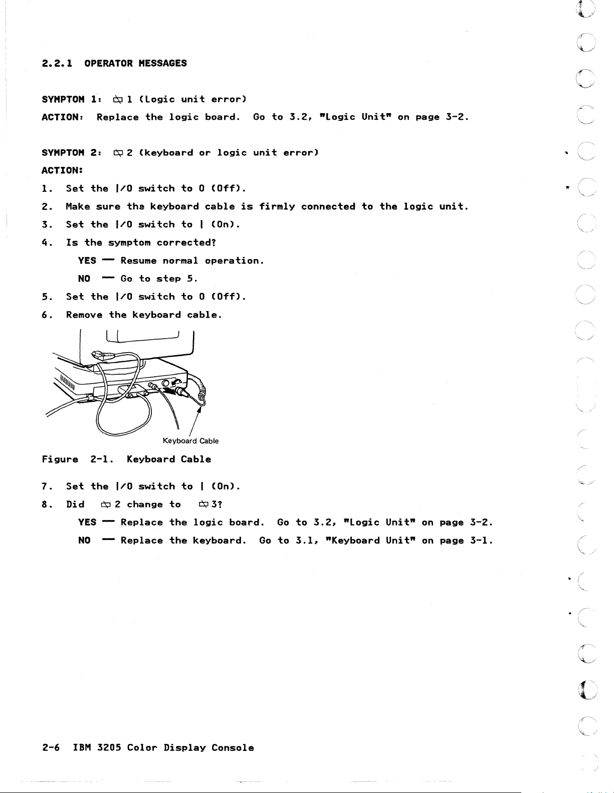
Remove
f:
Cs;J
Replace
2:
Cs;I2
the
I/O
sure
the
I/O
symptom
--
the
I/O
the
l-.l.L
1
(logic
the
(keyboard
switch
the
switch
Resume
Go
to
~witch
keyboard
__
unit
logic
to 0 (Off).
keyboard
to I (On).
corrected!
normal
step
S.
to 0 (Off).
cable.
-.-1
error)
board.
or
logic
cable
operation.
is
Go
to
unit
firmly
3.2,
error)
connected
ftLogic
Unitft
to
the
on
logic
page
3-2.
unit.
Figure
7.
Set
8 .
Di
2-1.
the
d
YES
NO
Cs;I
--
--
I/O
2
Keyboard
switch
change
Replace
Replace
Keyboard Cable
Cable
to I (On).
to
0;131
the
logic
the
keyboard.
board.
Go
Go
to
to
3.1,
3.2,
ftLogic
ftKeyboard
Unit"
Unit"
on
on
page
page
3-2.
3-1.
c
2-6
IBM
3205
Color
Display
Console
/
Page 31

(
(
C
c·
()-
c
SYMPTOM
ACTION:
1.
Set
2.
Make
Figure
3.
Set
4.
Is
Cs;J3
YES
NO
3:
the
su
2-2.
the
Cs;:l3
I/o
... e the
Keyboa
I/o
sti
11
Replace
Retu
(keyboC!l
switch
keyboa
Keyboard Cable
... d Cable
switch
di
splayed?
the
... n to
...
d e
...... o ...
)
.
to 0 (Off).
... d cable
to I (On).
keyboa
no
...
mal
...
d.
ope
is
fi
...
ation.
Go
...
mly
to
connected
3.1,
"Keyboa
to
the
... d Unit"
logic
on
unit.
page
3-1.
[
c·
c·
SYMPTOM
ACTION:
refer
to
~:
Fo
... a desc
the
Othe...
host
Messages
...
iption
processo
...
of
ope
othe
...
ato
...
host p ...
...
's
ocesso
guide.
...
's
ope
...
ato
...
info
...
mation a ...
eas,
C
'
,
Chapte
...
2. P ...
oblem
Determination
Guide
2-7
Page 32

----
2.2.2
~--------~~.~-~~.~~-.
POWER-ON
LIGHT
_.
~
..
-~~~---~--.
OR
-~
STATUS
---,
LIGHT
0
r\
~
PROBLEM
SYMPTOM
ACTION:
1.
2.
3.
4.
5.
5:
Set
the
Make
Reseat
Set
the
Does
NO
YES
6.
Unplug
7.
Set
the
8.
Does
NO
YES
9.
Set
the
10.
Unplug
sure
the
the
the
the
the
Power-on
I/O
switch
the
voltage
power
I/O
switch
Power-on
Set
the
Resume
keyboard
I/O
switch
power-on
Go
to
Replace
I/o
switch
video
light
to 0 (Off).
cord
to
light
I/o
normal
cable.
to I (On).
light
Step
the
to 0 (Off).
cable;
is
source
firmly
(on).
come
switch
operation.
come
9.
keyboard.
wait
not
on.
is
correct
in
the
on?
to 0 (off)
on?
30
seconds.
video
and
at
the
unit.
go
power
to
step
outlet.
6.
C
c=
o.
C~:
r-'
•
~J
C
(~
~j
:--~".
~j
/\
'",,-j
:-~
11.
Set
12.
Does
13.
Disconnect
Is
the
the
NO
YES
the
voltage
YES
NO
Video Cable
I/O
switch
power-on
Go
to
Replace
the
Exchange
Exchange
to I (On).
light
Step
13.
the
power
correct?
the
the
logic
cord
video
power
come
board.
from
on?
the
unit.
cord.
video
Go
unit
to
and
3.3.
check
"Video
for
Unit"
propel-
on
voltage.
page
3-6.
. (
I
"-
\
"'-',
Figure
2-8
IBM
2-3.
3205
Video
Color
Cable
Display
c
c
Console
Page 33

SYMPTOM
6.
Power-on
light
is
on,
but
Status
light
is
off.
('
c
()
•
•
()
c
c~
f
(/
ACTION:
Set
1.
2.
Set
Set
3.
4 . Did
YES
NO
5.
Is
YES
NO
6.
Set
7.
Set
8.
Set
9.
Is
YES
the
the
the
the
the
the
the
the
the
status
--
status
--
I/O
switch
Test/Normal
I/O
switch
alarm
I/O
Test/Normal
I/O
sound!
~o
to
Go
to
light
Go
to
Make
sure
you
still
on
page
switch
switch
light
Perform
Test
the
Step
Step
Step
3-2.
coaxial
to 0 (Off).
switch
to
5.
10 .
blinking?
6.
the
have a problem,
to 0 (Off).
switch
to I (On).
still
coaxial
(On).
I
video
cable
to
cable
to
off?
cable
Test.
Normal.
is
replace
check.
from
firmly
the
the
3205
connected
logic
to
the
to
unit.
host
the
logic
Go
system
to
as
unit.
"Logic
follows:
If
Unit"
[
(~\
(
(~,
()
.
()
.
C:!
C
10.
Set
11.
Disconnect
NO
a.
b.
c.
d.
• Yes - The
•
e.
• Open
• Open
• Open
If
host
Return
the
I/O
the
Ensure
Disconnect
Measure
cable
Is
processor
been
operation.
No -Go
Check
you
switch
to
the
to
for
or
or
or
cannot
processor.
to
normal
to 0 (Off).
video
the
coaxial
the
the
resistance
the
outer
resistance
coaxial
MI
to
one
find
if
If
step
of
operation.
from
START,
shorted
shorted
shorted
cable
cable
coaxial
case
between
cable
you
have
replace
the
3205
e.
the
coaxial
host
host
the
problem,
the
is
connected
cable
from
of
the
1.8K
check
not
the
logic
still
following
cable
system
system
cabling.
driver
invoke
logic
from
the
the
center
connector.
ohms
is
correct.
~lready
board
fails,
problems.
or
coaxial
card.
the
unit.
to
3205.
pin
and
2.6K ohms!
done
and
invoke
support
the
of
(Use
Go
so.
rerun
your
cable
system.
the
connector
the
to
START
If
you
the
support
connector.
structure
RxlO
failing
range.)
for
have
structure.
for
on
the
the
host
already
your
C
C';
fC
Chapter
2.
Problem
Determination
Guide
2-9
Page 34

12.
13.
Set
the
Measure
11'0
the
switch
following
to
(On).
I
voltages:
Figure
Pin
Pin
Pin
2-4.
5
7
12
(+5V)
(+5V)
(+12V)
Pin
Voltages
and
pin 9 (ground)
and
pin 9 (ground)
and
pi
n 9
in
(ground)
Video
Video Cable
~
o
Cable
+12 V de (Pin
3121110
0000000000000
H~~y~!~~g~~~~
GND
176
121
(Pin
.L
91
+5 V
4321~
de
(Pin
5 and 7)
0
c
(
i"
14.
Are
YES
NO
all
voltages
Replace
Replace
present!
the
logic
the
video
board.
unit.
Go
Go
to
to
3.2,
3.3,
"logic
"Video
Unit"
Unit"
on
on
page
page
3-2.
3-6.
c
2-10
IBM
3205
Color
Display
Console
Page 35

('
c
c
•
c
c
c'
(~
("
, ..
~
[
c\
2.2.3
SY"PTO"
DISPLAY
The
7:
bottom.
ABCDEFGHiIJKLMNOPQRSTUVW'XYZ123
ABCDEFGH'IJKLMNOPORSTUVWXYZI23
ABCDEFGHIJKLMNOPORSTUVWXYZ123
ABCDEFGHIJKLMNOPORSTUVWXYZ123
ABeD
EF
GH
IJKLMN
OPO
ABeD
EF GH IJ
ABC 0 EF GH
ABC 0
EF
GH
ABC 0
EF
GH
ABeD
EF G
H1JK
ABC 0 EF
GH
ABC 0 EF
GM
ABC
0 E
FGH
ABC
0 E F
GH
Figure
ACTION:
SY"PTO"
ABCDEFGHIJKLMNOPORSTUVWXYZ123
ABCDEFGHIJKLMNOPORSTUVWXYZ123
ABCOEFGHIJKLMNOPQRSTUVWXYZ123
ABCDEFGHIJKLMNOPQRSTUVWXYZ123
ABCDEFGHIJKLMNOPORSTUVWXYZ123
ABCDEFGHIJKLMNOPQRSTUVWXYZ123
ABCDEFGHIJKLMNOPORSTUVWXYZ123
ABCDEFGHIJKLMNOPORSTUVWXYZ123
ABCDEFGHIJKLMNOPORSTUVWXYZ123
ABCDEFGHIJKLMNQPQRSTUVWXYZ123
ABCDEFGHIJKlMNOPORSTUVWXYZ123
ABCDEFGHIJKlMNOPORSTUVWXYZ123
ABCDEFGHIJKLMNOPORSTUVWXYZ123
KLMN
opa
IJK
LMN
OPO
IJKLMN a PO
UK
LMN
opa
LMN 0 paRS
,JK
LMN 0 PO
IJK
LMN 0 PQRS
IJK
LMN 0 PO
IJK
Ltt'lN 0 PO
2-5.
Replace
8:
A5TUVW
RS
RS
RS
RS
RSTUVW X '(212
ASTUV
RSruvW x YZ12
The
PROBlE"
characters
XyZ123
TUVW
XYl123
TuvW
XyZI23
TUVW
XyZ12
TUVW
XYZ12
TUVW x yl123
TUVW X Y212
W X
YZl2
Display
display
3
3
3
3
3
3
the
A
video
is
at
unit.
the
or
the
correct
top
are
Go
width,
to
either
3.3,
"Video
but
larger
its
or
Unit"
height
smaller
on
page
is
not
than
3-6.
normal.
those
at
the
C'
C'
c;
j
C
c;
("
CI
c:
.
Figure
ACTION:
SYHPTO"
ACTION:
SYHPTO"
ACTION:
2-6.
Replace
9:
There
Replace
10:
Replace
Display
the
the
The
display
the
B
video
unit.
is a bright
video
unit.
is
video
unit.
horizontal
out
of
Go
Go
focus.
Go
to
3.3,
or
vertical
to
3.3,
to
3.3,
Chapter
"Video
"Video
"Video
2.
Problem
Unit"
line
Unit"
Unit"
on
page
in
the
center.
on
page
on
page
Determination
3-6.
3-6.
3-6.
Guide
2-11
("
Page 36

SYMPTOM
Figure
11:
....
CDEFGHIJKLMNOPOflSTUVWKYZI23
AaCOIEFGHIJKI.MNOf'QRSTUVWJlYZI23
AIlCOEFGHIJI(\.MNOI"QRSTUVWXVZl23
A8Ctl&FGHIJKLMNOPQRSTUVWXYZI23
AIICDEFGMIJI(lMNOl'ORSTUVW)CYZl23
MCDEfGHIJI(LMNOI"QRST1JVWX,(ZI23
AlCUEFGM'#;LMNOI'ORSTUWflI,YZI23
ABCDEFGHIJICLMNOPQRSTUYWXYZI23
AICDEfGHIJlCl.MNOl'QASTUVWXYZ
AIICDEFGHIJKLMNOI'ORSTUYWXYZl21
A8C0EFGHIJlCLMNOPORSTUVWX'fZ123
AllCDEFGHIJI(UIlNOl"QRSTUVWXYZ123
AecotFOMIJKLMNOPORSTUVWXYZ
A8CDEFGHUKLMNOPORSTUYWXYZI21
2-7.
The
display
121
123
Display
C
is
smaller
than
normal.
I'"~
v
(~
~.
c
c
"
'
(--.
~j
('
/
ACTION:
SYMPTOM
ACTION:
SYMPTOM
BCDE
FG
BCDEFGHIJKLMNOPQRSTUVWXYZ12
BCDEFGHIJKLMNOPQRSTUVWXYZ12
BCDEFGHIJKLMNOPQRSTUVWXYZ12
BCDEFGHIJKLMNOPQRSTUVWXYZ12
BCDEFGHIJKLMNOPQRSTUVWXYZ12
BCDEFGHIJKLMNOPQRSTUVWXYZ12
BCDEFGHIJKLMNOPQRSTUVWXYZ12
BCDEFGHIJKLMNOPQRSTUVWXYZ12
BCD
EFGH IJK LMNOPQRSTUVWXYZ 12
BCDEFGHIJKLMNOPQRSTUVWXYZ12
BCDEFGHIJKLMNOPQRSTUVWXYZ
Figure
ACTION:
Replace
12: The
Replace
13: The
HIJK
LMNOPQRSTUVWXYZ 12
2-8.
Replace
the
display
the
characters
Display
the
12
video
video
D
video
is
unit.
off
unit.
are
unit.
Go
center
and
Go
magnified.
Go
to
to
to
3.3,
the
characters
3.3,
3.3,
"Video
"Video
"Video
Unit"
are
Unit"
Unit"
on
page
3-6.
overlapping.
on
page
on
page
3-6.
3-6.
("
~/
(\
./
\.
~--"
( \
~)
(.---\
\,,-~
f'~
SYMPTOM
ABCDEFGHIJKLMNOPORSTUVWXYZ123
ABCDEFGHIJKLMNDPQRSTUVWXYZ123
ABCDEFGHIJKLMNDPQRSTUVWXYZ123
ABCDEFGHIJKLMNOPORSTUVWXYZ123
ABCDEFGHIJKLMNOPQRSTUVWXYZ123
ABCDEFGHIJKLMNOPQRSTUVWXYZ123
ABCDEFGHIJKLMNOPORSTUVWXYZ123
ABCDEFGHIJKLMNOPQRSTUVWXYZ123
ABCDEFGHIJKLMNOPQRSTUVWXYZ123
ABCDEFGHIJKLMNOPQRSTUVWXYZ123
ABCDEFGHIJKLMNOPORSTUVWXYZ123
ABCDEFGH1JKLMNOPORSTUVWXYZ123
ABCDEFGHIJKLMNOPORSTUVWXYZ
ABCDEFGHIJKLMNOPORSTUVWXYZ 123
Figure
ACTION:
2-12
U:
2-9.
Replace
IBM
3205
The
display
123
Display
the
Color
appears
E
video
Display
unit.
Console
to
Go
be
weaving.
to
3.3,
"Video
Unit"
on
page
3-6.
·c
c
c
:···.·
'~
,
c
,t("
.-...,
Page 37

c\
().
c
SYMPTOM
Figure
15:
2-10.
The
Display
display
F
is
tilted.
c
[
\
{
"
'C
ACTION:
SYMPTOM
left.
ACTION:
1.
Set
2.
Make
3.
Set
4.
Turn
5.
Make
6.
Set
7.
Does
NO
YES
8.
Is
the
NO
YES
Replace
16:
the
the
the
The
I/o
sure
I/o
the
security
sure
Test/Normal
the
symptom
Go
Return
status
Replace
Replace
the
display
switch
the
switch
the
to
video
appears
to 0 (Off).
video
Power-on
light
cable
back
key
switch
disappear?
step
8.
to
normal
continuously
the
logic
the
video
unit.
is
to I (On).
and
the
light
to
operation.
board.
unit.
Go
to
be
rolling
firmly
Brightness
is
on.
Test.
blinking?
to
3.3.
from
connected
Control
Go
to
3.2,
Go
to
3.3,
"Video
left
to
"logic
"Video
Unit"
the
knob
to
right
logic
fully
Unit"
Unit"
on
page
unit.
clockwise.
on
on
or
3-6.
from
page
page
right
3-2.
3-6.
to
()
c·
Figur~
2-11.
Status
light
Chapter
2.
Problem
Determination
Guide
2-13
Page 38

SYMPTOM
top.
17.
ACTION:
Set
Make
Set
Turn
Make
Set
Does
the
the
the
l.
2.
3.
4.
5.
6.
7.
NO
VES
8.
Is
the
NO
The
I/O
sure
the
sure
the
the
I/O
security
the
Test/Normal
symptom
Go
--
Return
Status
--
Replace
display
switch
video
switch
Power-on
to
step
to
light
appears
to 0 (Off).
cable
back
key
disappear!
normal
the
to I (On).
and
light
switch
8.
continuously
logic
to
be
is
firmly
the
Brightness
is
on.
to
Test.
operation.
blinking!
board.
rolling
connected
Control
Go
to
from
to
3.2,
top
to
the
knob
"Logic
bottom
logic
fully
Unit"
or
from
unit.
clockwise.
on
page
bottom
3-2.
to
If
>0
...
',""
c
c
)
Figure
VES
--
2-12.
Replace
Status
the
Status
Light
video
Light
unit.
Go
to
3.3,
"Video
Unit"
on
page
3-6.
.r
2-14
IBM
3205
Color
Display
c:
Console
Page 39

(
(~
(
c'
c
c
C
("
-~/
(~
(/
•
•
SVMPTOM
ACTION:
1.
Set
2.
Make
3.
Set
4.
Turn
5.
Make
NO
YES
6.
Set
7.
Does
NO
VES
S.
Is
the
VES
NO
181
The
the
I/O
sure
the
I/O
the
security
sure
Go
Go
the
Test/Normal
the
symptom
Go
Return
Status
Replace
Replace
switch
the
switch
the
to
to
to
display
video
key
Power-on
"Symptom
step
disappear?
step
to
light
the
the
has
no
picture
to 0 (Off).
cable
back
6.
switch
S.
normal
continuously
video
logic
is
to I (On).
and
the
light
5"
on
to
operation.
unit.
board.
firmly
Brightness
is
on.
page
Test.
2-S
blinking!
and
adjusting
connected
Control
.
Go
to
3.3,
Go
to
3.2,
to
the
knob
"Video
"Logic
the
logic
brightness
unit.
fully
Unit"
Unit"
clockwise
on
on
has
page
page
no
•
3-6.
3-2.
effect.
[
C':
(-'
C
c;
C
C
C
.
.
Figure
2-13.
Status
Status
Light
Light
C
c'
c
•
~t
Chapter
2.
Problem
Determination
Guide
2-15
Page 40

SYMPTOM
19r
ACTION:
1.
If
eyl,
2.
Turn
3.
Set
the
Characters
~2,
the
security
Test/Normal
or
~3
key
are
not
is
displayed,
off
switch
displayed
and
then
to
Test.
go
on
above
to
2.2.1
(fully
the
divider
Symptom
clockwise).
1,
line.
2,
or
3,
respectively.
o
c
c
c
Figure
4.
Are
YES
NO
S.
Set
6.
If
the
console.
7.
Test
a.
b.
c.
d.
•
• Yes - The
2-14.
characters
the
the
Ensure
Disconnect
Measure
the
Is
No -Go
processor
If
failing
for
Test/Normal
Go
to
Exchange
Test/Normal
$Ymptom
coaxial
the
the
outer
the
resistance
to
you
have
operation.
the
host
displayed
step
still
coaxial
the
case
step
coaxial
MI
S.
the
switch
cable
coaxial
resistance
of
e.
if
you
already
processor.
Switch
above
logic
continues,
the
between
cable
board.
back
from
the
cable
cable
from
connector.
check
have
been
If
the
the
to
check
320S
is
connected
from
the
1.8K
not
already
to
START,
320S
divider
Go
Normal.
that
to
the
center
(Use
ohms
is
correct.
still
line!
to
3.2,
the
the
host
to
320S.
pin
the
and
2.6K ohms!
done
replace
fails,
nLogic
coaxial
the
of
RxlO
Go
so.
the
Unitn on
system
system.
the
connector
range.)
to
START
logic
invoke
cable
as
board
your
page
is
attached
foilowsl
on
for
the
and
support
3-2.
the
cable
host
rerun
structure
to
the
the
to
,r-\
\
/
'''''------'
2-16
e.
Check
• Open
• Open
• Open
If
you
IBM
cannot
320S
processor.
for
or
or
or
Color
one
shorted
shorted
shorted
find
Display
of
the
coaxial
host
host
the
following
cable
system
system
problem,
Console
problemsl
or
coaxial
cabling.
driver
invoke
card.
your
cable
support
connector.
structure
for
your
host
.
c:'
c
Page 41

('
c
()
c-
c
c
(
(
SYMPTOM
characters
ACTION:
1.
Change
2.
Does
NO
YES
3.
Set
4.
Make
NO
YES
20:
the
the
sure
The
are
the
missing
Go
Return
I/O
the
Resume
Go
red,
missing
setting
to
step
to
switch
video
to
step
green,
on
the
of
the
color
3.
normal
to 0 (Off).
cable
normal
5.
or
blue
display.
color
appear!
operation.
is
firmly
operation.
color
(00/0000)
connected
does
not
switch.
to
appear
the
on
logic
the
unit.
screen,
or
some
[
c
(~
()
c'
Figure
5.
Set
6.
Turn
Set
7.
Is
8.
Figure
2-15.
the
the
the
YES
NO
2-16.
Video Cable
Video
I/O
the
security
Test/Normal
Status
Go
Replace
Status
switch
light
to
step
Cable
to
key
on
switch
continuously
9.
the
logic
Light
(On).
(fully
to
board.
clockwise).
Test.
blinking!
Go
to
3.2.
nLogic
Unitn on
page
3-2.
c'
c
9.
Do
red,
YES
NO
green,
--
The
problem
to
Normal.
support
Replace
and
blue
structure.
the
appear
is
not
Check
video
in
host
unit.
on
the
your
problem
Go
test
IBM
3205.
determination
to
3.3.
Chapter
pattern
Set
"Video
2.
Problem
(see
Figure
the
Test/Normal
procedures.
Unit"
Determination
on
1-4
page
on
switch
Invoke
3-6.
Guide
page
1-6)!
back
your
2-17
Page 42

SYMPTOM
21:
A
color
is
substituted
by
another
(f"',
'-'I
C
color.
ACTION:
1.
Change
2.
Does
NO
YES
3.
Set
4.
Make
Figure
s.
Set
the
the
the
sure
2-17.
the
setting
missing
Go
to
Return
I/O
switch
the
Video Cable
Video
I/O
switch
color
step
to
video
Cable
of
the
color
appear?
3.
normal
to 0 (Off).
cable
to I (On).
operation.
is
(00/0000)
firmly
switch.
connected
to
the
logic
C
c
unit.
c
6.
Turn
7.
Set
8.
Is
Figure
9.
Do
the
the
YES
NO
2-18.
red.
YES
NO
the
security
Test/Normal
Status
Go
Replace
Status
green.
--
The
to
support
Replace
light
to
step
the
Status
and
problem
Normal.
structure.
the
key
on
(fully
switch
continuously
9.
logic
light
Light
blue
appear
is
not
Check
video
to
Test.
board.
on
in
your
host
unit.
clockwise).
blinking?
Go
to
the
test
IBM
problem
Go
3205.
determination
to
3.3.
3.2.
pattern
nLogic
Set
nVideo
Unit"
(see
Figure
the
Test/Normal
procedure.
n
Unit
on
on
page
1-4
page
3-2.
on
page
switch
Invoke
3-6.
1-6)?
back
your
c
2-18
IBM
3205
Color
Display
Console
Page 43

c
()
()-
SYMPTOM
underscore)
ACTION:
1.
Set
22:
the
Problems
.
Test/Normal
with
switch
highlighted
to
Test.
characters
(reversed,
blinking,
or
c
c
Figure
2.
(
4[~
SYMPTOM
ACTION:
SYMPTOM
[
ACTION::
C'
('
C
SYMPTOM
ACTION:
1.
2.
3.
4.
Are
YES
NO
Set
Wait
Set
Does
2-19.
there
23:
Replace
24:
Replace
25:
the
I/O
around
the
I/o
your
Test/Normal
highlighted
Invoke
Replace
Characters
Characters
Part
symptom
your
the
the
of
switch
15
minutes.
switch
Switch
characters
support
the
logic
are
deformed
logic
your
board.
on
the
logic
remain?
board.
screen
to 0 (Off).
to I (On).
structure.
board.
Go
screen
becomes
in
or
Go
the
Go
parts
to
are
to
test
to
3.2,
are
3.2,
"logic
replaced
3.2,
reddish,
pattern?
"logic
added
with
"Logic
greenish,
or
Unit"
other
Unit"
Unit"
missing.
on
on
or
on
page
page
characters.
3-2.
page
bluish.
3-2.
3-2
C
\
..
'
C
c·
c
YES
NO
5.
If
your
page
SYMPTOM
ACTION:
1.
Replace
2.
If
the
Unit"
3-6.
26:
on
Repeat
Return
symptom
Other
the
video
symptom
page
steps
to
remains,
display
unit.
still
3-2.
1,
normal
problems.
continues,
2,
and
operation.
replace
Go
to
3.3,
3;
then
the
"Video
replace
Chapter
go
video
the
to
step
unit.
Unit"
logic
2.
5.
Go
to
on
page
board.
Problem
3.3,
"Video
3-6.
Go
to
3.2,
Determination
Unit"
"logic
Guide
on
2-19
Page 44

c
SY"PTO" 27:
Figu~e
ACTION:
2-20.
Replace
Keyed-in
Without-Cu~so~
the
ehe~acter
logic
boa~d.
appea~s,
Cha~acte~
Go
to
but
3.2,
the
"Logic
cu~so~
does
Unit"
on
not.
page
c
3-2.
C~
2-20
IBM
3205
Colo~
Display
Console
"
,"\
C
j
----'.-
---
Page 45

(
(~'
(~
c
·
c
•
c
Ci
C
(
{
2.2.4
SYMPTO"
Figure
ACTION:
1.
Set
2.
Is
KEYBOARD
28:
You
2-21.
the
the
All
Test/Normal
Status
PROBlE"
cannot
Characters
light
type
switch
continuously
in
any
to
characters.
Test.
blinking?
r
c'
("
c
('~';
("
_/
(\
C
"
C
Figure
3.
4.
•
·
2-22.
YES
NO
If
0;11,0;12,
Can
you
YES
NO
Status
Go
to
Replace
type
Return
Replace
or
in
step
the
Cs;I3
now?
to
the
light
3.
logic
is
normal
keyboard
board.
displayed,
operation.
unit.
go
Go
to
to
3.2,
2.2.1
"logic
Symptom
Unit"
1,
2,
on
or
page
3-2.
3,
respectively.
C
C
Chapter
2.
Problem
Determination
Guide
2-21
Page 46

SYMPTOM
func
tiona
29:
1.
You
cannot
type
in
some
characters
or
some
control
keys
are
()
o
not
Figure
ACTION:
SYMPTOM
Figure
ACTION::
SYMPTOM
2-23.
Replace
30:
2-24.
Replace
31:
Some
the
Characters
Automatic
the
Pressing
Characters
keyboard.
appear
Characters
keyboard.
a
key
Go
automatically
Go
once
causes
to
to
3.1.
3.1.
more
"Keyboard
without
"Keyboard
than
one
Unit"
typing
Unit"
character
on
them.
on
page
page
to
3-1.
3-1.
appear.
Figura
ACTION:
2-22
2-25.
IBM
Replace
3205
Double
the
Color
Characters
keyboard.
Display
Go
Console
to
3.1.
"Keyboard
Unit"
on
page
•
3-1.
Page 47

(-
("
c
().
SYMPTOM
32:
Keyed-in
characters
-----------~-~----
are
different
from
the
key
caps.
c-
c
'
(
, /
(
(
[
()
('
Figure
ACTION:
1.
Set
Make
2.
label.
3.
Do
2-26.
the
sure
the
YES
NO
Different
I/O
switch
the
switches
Go
to
Correct
setup
match
step
the
Characters
to 0 (Off).
switches
the
label!
4.
setup
switch
underside
setting.
the
keyboard
~tBffi8iii
Switches
are
set
as
shown on
your
6-,.
~/
,
.
C
.
,/
,
(
/
c!
Figure
4.
Set
s.
If
2-27.
the
the
Membrane
Setup
I/O
switch
symptom
Type
Switches
back
remains,
to I (On).
replace
the
logic
Chapter
board.
2.
Capacitance
Problem
Type
Determination
Guide
2-23
Page 48

2.2.5
SY"PTO"
AUDIBLE
33:
Audible
ALAR"
PROBlE"
Alarm
sounds
continuously.
t'.
"
,
.,
~
I
C
c
c
·c
Figure
ACTION:
1.
Set
2.
Set
3.
Does
YES --Replace
NO
SY"PTO"
2-28.
the
it
back
the
--
3~:
Audible
I/O
switch
to I (On).
Audible
Return
Audible
Alarm
to 0 (Off).
Alarm
the
logic
to
normal
Alarm
still
board.
operation.
does
sound
not
continuously?
Go
to
sound.
3.2.
"logic
Unit"
on
page
3-2.
('"
\ J
'. /
Figure
ACTION:
1.
Set
2-24
IBM
2-29.
the
3205
I/O
No
Alarm
switch
Color
to 0 (Off).
Display
Console
Page 49

(
("
(,
C
().
c·
c
c
(
2.
Figure
3.
4.
Make
Set
sure
2-30.
the
Turn
the
clockwise.
the
Video Cable
Video
I/o
switch
Audible
video
Cable
Alarm
cable
to I (On).
is
Volume
firmly
Control
connected
Knob
at
to
the
the
back
logic
of
unit.
the
logic
unit
fully
(--
[
"~'
\
C
C
(~
(J
c)
~
i
~
C
'/'
Figure
5.
Set
6.
Does
YES
NO
2-31.
the
Test/Normal
the
Audible
Audible
Return
Replace
Alarm
to
the
Alarm
switch
sound?
normal
logic
Control
to
Test.
operation.
board.
Knob
Go
to
3.2,
"Logic
Unit"
on
page
3-2.
C~
C
C'
t
Chapter
2.
Problem
Determination
Guida
2-25
Page 50

r(
-,
'v
2.2.6
SYMPTOM
Figure
ACTION:
1.
2.
3.
MONOCASE/DUALCASE
35:
2-32.
Set
the
While
(A/A,a)
Do
the
YES
Monocase/Dualcase
Monocase/Dualcase
Test/Normal
looking
several
characters
Invoke
at
the
times.
change
your
SWITCH
switch
display,
from
support
PROBLEM
(A/A,a)
(A/A,a)
to
Test.
alternately
all
structure.
switch
Switch
uppercase
does
switch
to
not
work.
between
uppercase
Monocase
and
lowercase?
and
c
c
Dualcase
NO
Replace
the
logic
board.
Go
to
3.2,
"logic
Unit"
an
page
3-2.
2-26
IBM
3205
Color
Display
Console
c
·
C
,"
-
.'
\
Page 51

(~
(
2.2.7
COLOR
SWITCH
PROBLEM
c
c
c
c
(
(~'
.•
[
SYMPTOM
Figure
ACTION:
1.
2.
3.
Set
look
the
Do
YES
NO
36:
2-33.
the
opposite
some
Color
Color
Test/Normal
at
the
of
the
Invoke
Replace
(00/0000)
(00/0000)
characters
position.
characters
your
the
switch
on
support
logic
switch
Switch
to
the
change
structure.
board.
does
Test.
test
color?
not
pattern
Go
to
work.
and
3.2,
set
"logic
the
color
Unit"
(00/0000)
on
page
3-2.
switch
to
"
c·
c:
C
Chapter
2.
Problem
Determination
Guide
2-27
Page 52

2.2.8
PEDESTAL
The
OR
POWER
pedestal
CORD
or
PROBLE"
the
power
cord
is
broken
or
malfunctioning.
Pedestal
Figure
To
remove
page
3-2.
Power
Problem
2-34.
Cord
the
pedestal
Discard
Problem
Pedestal
the
from
broken
the
video
pedestal.
and
logic
units,
refer
to
3.2,
"Logic
Unit"
o
on
Figure
Set
cord.
2.2.9
2-35.
the.
I/o
SECURITY
4 Position
Connector
IIJ
II:]
II:]
II:]
Polarization Key
Figure
2-36.
ACTION:
1.
Disconnect
removal
2.
Make
3.
Are
the
swi
~----~
procedures
the
continuity
continuity
Power
tch
Cord
to 0 (Off)
KEY
PROBLE"
and
Security Keylock
Switch Mechanism
r---------,
I I
I I
L
_________
Security
the
Key
security
for
tests
checks
Failure
key
the
shown
for
from
logic
unplug
the
unit
for
the
security
the
I
Make
I
I
Break
I
I
.J
logic
cover.)
the
power
.••.•••.
...•...•
board.
security
key
cord.
At
Horizontal Position
At
Vertical Position
assembly
Di
(See
key.
scard
Section
correct?
the
broken
3.2.1
for
power
the
c
2-28
•
•
Yes
No
IBM
-
-
3205
Replace
Replace
Color
the
logic
the
security
Display
board.
Console
key
assembly
•
Page 53

().
c
2.3
OFFLINE
The
IBM
Test/Normal
1.
2.
3.
4.
5.
6.
7.
At
the
the
the
an
3205
Basic
Basic
Video
logic
a.
b.
All-character
Color
Setup
Keyboard-to-display
the
test
Figure
cursor
underline.
Assurance
logic
Interface
unit.
Keyboard
circuit
Keyboard
Pattern
Switches
entry
pattern
2-37
is
TESTS
offline
switch
Test:
Interface
in
Test:
Display
Display
of
the
appears
on
rectangular
tests
is
set
Test
tests
Test:
the
and
offline
page
are
to
Test#
(BAT)
the
tests
Test:
logic
Jumpers
unit.
tests
Test
(7
Color
Operation
tests#
and
the
2-30.
and
in
the
the
functions
the
tests
the
function
Pattern
Status
Test.
the
status
At
the
blinking.
IBM
3205
offline
of
function
the
Display
alarm
light
entry
When
logic.
tests
the
of
function
of
the
and
2/4
Test
sounds
blinks.
of
the
any
Activated
consist
logic
the
keyboard.
key
unit.
video
of
the
Color
once.
The
keyboard-to-display
is
of
interface
keyboard
Pattern)
Several
test
pressed,
when
the:
interface
Test
seconds
pattern
the
the
circuit
is
operation#
cursor
in
later#
shown
becomes
the
in
[
c
c'
.
c
()
Chapter
2.
Problem
Determination
Guide
2-29
Page 54

c
Field
o
e{
e{
e{
e{
012345';7>
ael
ABCDEFGHIJKLMNOPQRSTUVWXYZ~BA~;*
eeeeeeee eeeeeeee
eeeeeeee
BBBBBoe1
< [ 1 )(){ =
QUae
i
QUae;
Red Green Blue
Green! Blue!
Red reverse image
_
'"
/\
6ui'IA£iOi:JADYAEEIOUYCAEIOOAE:iOOA~i6UNabcdef9h
@@!@!@@@
blinking
\ \ I " , I
eeeeeeee
, " I I r \
aBBBBBBe
TEST
I :
?I
$¢£¥R1I012345b78q~§·e%_&-.
White
( 4 colors
@!!!!!!@
White!
underscored Pink
~
shown)
!!!!!!!@
, :
+..,-.
Yellow
@@I!@@I!@@
Turquoise
@@@!@I!@@
i
jk
......, I
ae
i
ouaoyaee
ImnopqrstulJl';/yzlBa~;*
i
OUU~
Divider Line
1
c:
o
'"
r-~
'-~-
Note: This keyboard assembly
Bit 7 is
Figure
2-30
2-37.
IBM
off
3205
and
bit 8 is
Offline
Color
Field
Field
Field
Field
Field
Field
is
on. And all jumpers
Test
Display
All-character pattern
0
2
or
•
7-Color pattern
e
Setup switches
e
Flashing block cursor
e
Keyed-in characters
e
a UK-English keyboard.
Pattern
Console
4-Color pattern
are
off.
are
entered in this line.
:-
\.,-~.>',
~
"-
~~
I
~j
~
•
0
.
r
\'----./
~~
(
"~oj
£~\
L
C
Page 55

(-
("
C
().
c
c
2.3.1
Preparatlon
1.
OFFLINE
Set
the
Dualcase
=
Figure
2.
3.
logic
Turn
Does
Ves
2-38.
Turn
Turn
Check:
the
the
TEST
Test/Normal
(A,a),
Switches
the
Security
the
Audible
IBM
3205
alarm
No
I
Hote
the
PROCEDURE
switch
and
the
Setting
Keylock
Alarm Volume
power
sound
once?
e~ror
to
Color
clockwise
on.
condition
Test,
switch
Control
and
return
the
Monocase/Dualcase
(00/0000)
(horizontal
Knob
fully
to
to
2.2,
the
0000
position).
clockwise.
"Symptom
switch
position.
Index"
(A/A,a)
on
page
to
2-4.
c
c
I
Does
an
the
Operator
No
I I
I
I
I
Is
the
status
Ves
I
I
I
Does
the
Ves
I
Go
to
the
error
Ves
Hote
No
I
Hote
test
No
I
Note
next
message
Information
the
error
light
the
pattern
the
page.
blinking?
error
error
(~1'Cs;I2,
Area?
condition
condition
appear?
condition
ort:s;J3)
and
and
and
appear
return
return
return
to
to
to
in
2.2,
2.2,
2.2,
"Symptom
"Symptom
"Symptom
Index"
Index"
Index"
on
on
on
page
page
page
2-4.
2-4.
2-4.
c
Ci
-----"
...
_-_
...
_-- -
Chapter
..
-
--------.-----~-----
2.
Problem
Determination
Guida
2-31
Page 56

'0
r
V
C
Character
Is
the
Vas
I
to
Go
(I"
aelouae
ABCDEFGHIJKLMNOPQRSruvWXYZ~eA~;*
Note:
Display
all-character.
No
I
Note
the
iJii5~7>
This
the
next
([])
()
i
6i1ae;
oui'iAEibOiiDYAEEIOUYCAEliiOAEi6uA£i6UNabcdefgh
pattern
Check:
error
page.
(
='"
appears
dualcase
condition
/\
I
:?
1
$¢i¥Rlt012345b78Q&§le%_&-,
when
pattern
and
the
122-key
correct?
return
to
2.2.
,:
+
.,-.,
A
i jk
keyboard
"Symptom
....
' , J
ae;
ouaoyaeei
ImnopqrstulI";,,<:yzlBa~;*
is
attached.
Index"
OUlJ~
on
page
2-4.
•
U
~,
r
\~'
C
c:
('
~i
_/
~
~
./
/'"
0>"
~
Figure
Note:
2-39
0'2
34Sb7)\ [ ])(){
,.·'Ht:i(:;),)t7'1*1':"Jt1'13"JI4·0.,j" 0 0 r
AB(DEFGHIJKLMNOPQRSTUVWXYZ~eA~i*
This
(Part
pattern
1
of
='"
/\
appears
2).
I
:?I
All-character
$¢i¥Rlt012345b78Q&§le%_8c-.
J'
•
'H
?IH
13,-"
when
the
124-key
attached.
Figura
2-39
(Part
2
of
2).
All-character
Pattern
,:
+
bcdefgh
a
Pattern
in
Dualcase
~-.,.
"",
, J
i'1'''H",*77J'1~
i jk
ImnopqrstullwxyzlBa~;;
keyboard
(Japanese
in
Dualcase
(A,a)
7t'/9
Katakana)
(A,a)
is
/
I
2-32
IBM
3205
Color
Display
Console
0"
~I
:
Page 57

C
C:
().
c·
':
C
/
(
(
Monocase/Dualcase
Set
the
position.
Is
Yes
I I
I
I
Go
Monocase/Dualcase
the
all-character
No
Note
the
to
the
next
(\
I iJ4Sili><
Ae:I(JUAE:i60Mf6uNAfiOUi!iOYAEEIOUYCAEi(JUAE:i6UA£iouNABCDEFGHIJKLMNOPQRSTUVWXYZfi0A~;*
ABCDEFGHIJKLMNOPQRSTUVWXYZfi0A~;*
[j)
page.
(){
Switch
error
;;'"
/\
I
Check:
switch
pattern
condition
:?
I
$¢£¥RJl012345b78Q&§le%_&-.,:
(A/A,a)
changed
and
to
to
the
return
the
Monocase
monocase
to
2.2,
+
~-.
"
.....
(A)
pattern?
"Symptom
'J
Af i bllAOYAEE
Index"
I
au
t·:
on
page
2-4.
c;-
Nate:
Figure
Nate:
attached.
Figure
This
pattern
2-40
0'
<34Sb7
"','H t
ABCDEFGHIJKLMNOPQRSTUVWXYZfi0A~i*
This
2-40
> d
:XVI)t
pattern
(Part 1 of
l)(}{
7'\*":
(Part
appears
2).
=
"'1\
I
:?
I
41ff
13'1) ""0,):'''' • r J ' •
appears
2
of
2).
when
$¢£¥RJl012345b78%§le%_&-.,:
the
All-character
'74
?
U,
when
the
All-character
122-key
13'
-"ABCDEFGH·I
124-key
keyboard
Pattern
+
~-.
H
J
keyboard
Pattern
is
attached.
in
Monocase (A)
.....
, , J i'i'''I:tM:;7J't:,-;;t')}
KLMNOPQRSTUVWXYZfi0A~;"
(Japanese
in
Monocase
Katakana)
(A)
is
c
Chapter
2.
Problem
Determination
Guida
2-33
Page 58

o
Color
Is
the
Display
7-color
Check:
pattern
displayed
correctly?
aaaaaaaa aaaaaaaa aaaaaaaa aaaaaaaa aaaaaaaa
I I I
I I
I
Blue/blinking
Pattern
error
pattern
condition
Figure
Yes
I
I
the
Is
J
Green/reverse
2-41.
No
J
Note
the
2/4-color
7-color
aaaaaaaa aaaaaaaa aaaaaaaa
I
I
I
Red
Blue
White/underscored
image
and
displayed
~hite
Pi
nk
return
correctly
I J
I
Yellow
to
2.2,
(4-color
Turquoise
"Symptom
pattern)
Index"
?
on
page
·c
2-4.
Figure
Yes
I
Set
the
Is
the
2/4-color
aaaaaaaa
I
J
White
Figure
Yes
I
to
Go
the
2-42.
No
I
Note
the
Color
aaaaaaaa
I
Green
2-43.
No
J
Note
the
next
4-color
error
switch
pattern
Pattern
condition
(00/0000)
displayed
aaaaaaaa aaaaaaaa
J J
J
Green
2-color
error
page.
Pattern
condition
and
to
the
White
and
return
00
correctly
position.
return
to
2.2,
(2-color
to
2.2,
"Symptom
pattern)
"Symptom
Index"
?
Index"
on
on
page
page
2-4.
,f~'\
2-4.
-c
2-34
IBM
3205
Color
Display
c
Console
Page 59

setup
Switches.
security
Keylock, and Cursor
Display
Check:
c·
c·
c
Check
(if
applicable)
Note: The
On
the
Underside
00000000
1 1
Figure
Are
Yes
2-44.
the
I
Turn
the
the
Does
Yes
the
switch
Setup
setup
No
,
Note
security
test
No
I
Note
setup
settings
of
the
00000000
1-11-1
I
!gnore
Jumpers
switches
Setup
switches
the
error
keylock
pattern
the
error
switches
inside
depend
Keyboard"
status------
status-----
Switches
and
condition
disappear?
condition
on
the
the
keyboard.
keyboard
on
language
on
page
>Japanese
Others
>
Ig~Fxxxxl
and
Jumpers
jumpers
counter-clockwise
correct
and
and
return
return
and
configuration.
A-2.
Katakana
1 2
3 4
Status
(equal
to
(vertical
to
the
2.2,
2.2.
Katakana
keyboard:
Ig~F
to
setting)
"Symptom
position).
"Symptom
jumper
See
123
X X X
?
Index"
Index"
A.l.
0001
0000
4
xl
"Set
on
on
Switches
page
page
2-4.
2-4.
()
(.~
I
Turn
the
Does
the
Yes
I
J
I
Is
the
Yes
rectangular
I
I
I
Press
Does
Yes
I I
I
I
Go
to
any
the
the
security
test
No
I
Note
No
I
Note
key.
cursor
No
Note
next
pattern
the
the
change
the
page.
keylock
error
cursor
error
error
clockwise
appear
condition
displayed
condition
to
the
condition
again?
and
and
underline
and
(horizontal
return
and
blinking?
return
cursor
return
to
to
to
2.2.
and
position).
"Symptom
2.2.
"Symptom
stop
2.2,
"Symptom
Index"
Index"
blinking?
Index"
on
on
on
page
page
page
2-4.
2-4.
2-4.
(
Chapter
2.
Problem
Determination
Guide
2-35
Page 60

Keybgard
Set
the
Perform
keyed-in
See
Figure
Does a
No
I I
I
I
I
Set
the
Are
TEST
cleared!
Yes
I I
I
I
I
Offline
Operation
Monocase/Dualcase
the
symbols
2-45
keyboard-to-display
Yes
Note
Test/Normal
in
No
Note
tests
Check:
keyboard-to-displaY
with
keys
page
error
switch
error
completed
the
the
the
are
on
Operator
switch
that
2-37
for
problem
condition
to
Information
condition
Normal.
successfully.
(A/A.a)
operation,
you
pressed.
symbols
exist!
and
return
Area
and
return
to
Dualcase
and
that
to
and
to
compare
should
2.2.
the
test
2.2.
(A.a).
be
displayed.
"Symptom
pattern
"Symptom
Index"
Index"
on
on
page
page
c
2-4.
-c
2-4.
Test
the
coaxial
a.
Ensure
b.
Disconnect
c.
Measure
the
d.
Is
the
•
•
e.
Check
• Open
•
• Open
If
you
processor.
cannot
cable
the
coaxial
the
the
outer
resistance
No -Go
Yes - The
processor
to
START.
the
processor.
for
Open
case
3205
one
or
or
or
find
resistance
to
shorted
shorted
shorted
from
coaxial
of
step
coaxial
MI
replace
still
of
the
the
cable
the
connector.
between
e.
cable
if
you
the
fails,
the
following
coaxial
syste~
system
problem.
3205
is
cable
from
1.8K
have
logic
invoke
to
the
connected
from
the
center
ohms
check
not
already
board
your
problems:
cable
cabling.
driver
invoke
host
the
(Use
and
is
correct.
or
coaxial
card.
the
system
to
the
3205.
pin
of
the
RxlO
2.6K ohms!
done
and
rerun
support
support
as
system.
the
connector
range.)
Go
to
so.
the
structure
cable
structure
follows:
START
If
you
failing
connector.
for
have
for
for
on
the
cable
the
host
already
operation.
the
host
your
host
to
been
If
"'--
2-36
IBM
3205
Color
Display
c
Console
Page 61

Nates:
1.
Regardless
are
2.
When
is
displayed.
3.
122-key
displayed
any
displayed.
key
Keyboard.
of
which
in
in
the
When
characters
test
shaded
the
mode.
key
area
is
appear
is
pressed,
released,
on
the
the
key
tops,
the
character
character
the
with
characters
without
the
underscore
shown
the
below
underscore
is
c·
c·
c
.•
[
, /
4.
The
test
Figure
characters
mode.
2-45
(Part
represented
1
of
2).
in
this
Characters
figure
displayed
will
be
in
displayed
the
Keyboard-to-display
when
the
3205
is
test
in
("
(~
CI'
c·
Chapter
2.
Problem
Determination
Guide
2-37
Page 62

Notes:
1.
Regardless
are
2.
When a key
is
displayed.
3.
~24-key
4.
The
test
those
displayed.
characters
mode.
shown
Keyboard
of
which
in
the
When
represented
characters
below
shaded
the
(Japanese
in
test
area
key
appear
mode.
is
pressed,
is
released,
Katakana).
in
this
on
figure
the
the
the
will
key
tops,
character
character
be
displayed
the
without
with
characters
the
the
underscore
when
the
displayed
underscore
3205
is
is
in
c
~
~
C
C'
.
C
r
o-
~--"
C)
r'"
~
~j
..
'
/
Figure
2-45
(Part
2
of
2).
Characters
displayed
in
the
Keyboard-to-displaY
test
~\
""-.
i'\
/
2-38
IBM
3205
Color
DisplaY
c
Console
Page 63

(
('
(
(~
c!
C
C
C
(
(
CHAPTER
This
chapter
3.1
1.
Set
2.
Unplug
3.
Disconnect
4.
Turn
5.
Set
6.
Record
7.
Reinstall
KEYBOARD
3.
REMOVAL
describes
the
I/O
the
the
the
setup
the
UNIT
power
the
new
switch
in
AND
switch
cord
keyboard
keyboard
switches
reverse
REPLACEMENT
how
to
remove
to 0 (Off).
from
the
cable
over.
on
the
setting
order.
on
the
PROCEDURES
and
replace
power
from
new
outlet.
the
keyboard
label
logic
supplied
to
the
unit.
match
console
the
with
the
FRUs.
old
new
keyboard
keyboard.
settings.
[
C
(-
C
c!
C'
c)
C
..
L
C'
("
Chapter
3.
Removal
and
Replacement
Procedures
3-1
Page 64

3.2
The
LOGIC
logic
UNIT
unit
consists
of:
• Top
•
• A
3.2.1
(See
1.
2.
3.
4.
and
A
logic
security
LOGIC
Figure
Turn
Remove
Disconnect
Hold
facing
CAUTION
Avoid damaging
5.
Pull
pedestal
6.
While
reinstalling.
7.
Pull
8.
Return
bottom
board
UNIT
3-1
power
the
the
video
up.
the
logic
is
pushing
the
pedestal
the
covers
assembly
keylock
COVER
on
page
off
and
power
the
three
unit
the
unit
visible.
latch
)
pedestal
which
assembly.
3-3)
disconnect
cable
connectors
in
units
slightly
~
e
towards
e
from
both
and
to
and
are
the
the
hands
the
towards
the
you
the
not
replaceable
power
video
t)
from
and
pedestal.
right,
and
logic
cord
unit
turn
you
pull
remove
unit
and
the
the
until
down
0
in
plug
unclamp
logic
video
the
the
it
from
to
the
from
unit.
gray
logic
their
field
the
it
unit
the
power
from
so
latch
unit.
video
normal
outlet.
the
that
~
unit
position.
cable
the
in
(See
screen
the
note
8.
clamp.
is
when
9.
10.
11.
12.
13.
14.
15.
Align
Squeeze
from
Invert
Return
Press
top
Repeat
the
Reinstall
the
the
the
cover
base
Note:
slots
onto
and
the
tab
the
logic
the
the
right
step
cover
in
When
lift
video
on
the
center
unit
logic
logic
0
unit
unit
plastic
far
enough
13
for
• .
reverse
reinstalling,
the
unit
logic
gray
O.
0,
0
the
left
sequence
logic
8.
unit
latches
then
to
tab
e
to
release
plastic
instead
unit.
with
remove
its
inward
except
Finally,
the
~
to
normal
the tab
tab
for
of
step 5 and
notch
the
the
position.
with a screwdriver
~.
steps
ensure
on
center,
single
•.
Then
5,
the
screw
6,
6,
the
pedestal.
and
lift
and
insert
pedestal
remove
8.
and
the
7.
the
the
push
top
hooks
has
pedestal
upward on
cover
into
been
locked
0
the
e
the
from
.'-..
.....
3-2
IBM
3205
Color
Display
Console
Page 65

(
('"
("
c~
c·
.
c~
c·
c·
(
(
r
r-------
<¢
(INVERT)
c~
{'
(:
()
c·
c·
Ci
C/·
C
Figure
3-1.
logic
Unit
Cover
Chapter
3.
Removal and
Replacement
Procedures
3-3
('
Page 66

o
c
3.2.2
(See
1.
2.
3.
4.
LOGIC
Figure
Remove
Unlatch
Keylock
Remove
Reinstall
BOARD
3-2)
the
logic
the
key
assembly).
logic
in
board
reverse
ASSEMBLY
unit
cover"
lock
connector
assembly
sequence.
~
e .
as
described
and
remove
under
it
"logic
(See
Unit
Figure
Cover."
3-3
c
Security
c
Figure
3-2.
logic
Board
Assembly
\"':.......
"---
..
/'
3-4
IBM
3205
Color
Display
Console
,\
C
,
.'
Page 67

(
{~
4L
(~'
c·
C~
C
c
(
(
3.2.3
(See
1.
2.
3.
4.
S.
SECURITY
Figure
Remove
Unlatch
Remove
Remove
Reinstall
3-3)
the
the
the
the
in
KEYLOCK
logic
clip
keylock
unit
key
lock
e
~everse
ASSEMBLY
cover
connector
from
the
swi
tch
e
sequence.
as
described
0
keylock
from
from
switch.
the
under
the
base
"logic
logic
cover.
Unit
board.
Cover."
[
c·
(/
Latched
Figure
Unlatched
3-3.
---0
Security
Keylock
Assembly
()
"",\
(
"
C
,I
Chapter
3.
Removal
and
Replacement
Procedure5
3-5
Page 68

3.3
1.
Set
2.
Unplug
unlock
3.
Disconnect
4.
Turn
S.
Pull
6.
Push
7.
Turn
8.
Attach
slots
9.
Turn
10.
Connect
11.
Connect
cable
VIDEO
the
the
the
the
the
the
UNIT
I/O
the
the
video
logic
latch
new
the
and
lifting
unit
all
the
clamp.
switch
power
cable
all
video
video
right
cables
power
to 0 (Off).
cord
clamp.
cables
unit
unit
to
so
slightly
the
unit
pedestal
the
side
to
cord
from
from
that
right
so
logic
up.
the
to
the
the
the
towards
to
that
to
the
unit
logic
the
power
logic
screen
unlock
the
new
slightly.
unit.
video
outlet
unit.
faces
you
the
screen
video
unit
and
up.
and
locate
pedestal
faces
unit
and
to
the
from
up.
by
inserting
the
video
the
gray
the
power
unit.
latch.
video
the
outlet.
Push
unit.
hooks
Lock
the tab
into
the
c
to
the
3-6
IBM
320S
Color
Display
Console
.r
l
',,-/
·c
r
\",
,/
Page 69

(
(
(
....
CHAPTER
"
4.
3205
PART
NUMBERS
C'
C:
~
c·
C
(,"
(
(
[
Figure
4-1
through
Figure
4-2
provide
the
part
numbers
for
I
the
IBM
3205.
(~
(~
(
CJ
c\
.
C:
.
C'
C
c~
(:-
Figure
4-1
(Part
1
of
4).
IBM
3205
Final
Assembly
Chapter
4.
3205
Part
Numbers
4-1
Page 70

v
c
FIGURE-
INDEX
NUMBER
1
1 6238412
1
1
1
PART
NUMBER
6238411
6238413
6238414
6238415
UNITS
PER
ASM.
REF
REF
REF
REF
REF
123
VIDEO
BERMUDA,
VIDEO
BAHAMAS,
COLUMBIA,
DOMINICAN
GUATEMALA,
HONDURAS,
KOREA,
NICARAGUA,
TAIWAN,
VIDEO
BOLIVIA,
VIDEO
AUSTRIA,
BULGARIA,
FINLAND,
HUNGARY,
ISRAEL,
LEBANON,
POLAND,
SPAIN,
UK,
VIDEO
AUSTRALIA,
4
UNIT,
CANADA,
UNIT,
BARBADOS,
COSTA
REPUBLIC,
GUYANA,
JAMAICA,
MEXICO,
PANAMA,
TRINIDAn,
UNIT,
ECUADOR,
UNIT,
BAHRAIN,
DENMARK,
FRANCE,
ICELAND, IRELAND,
ITALY,
NETHERLANDS,
PORTUGAL,
SWEDEN,
YUGOSLAVIA.
UNIT,
NEWZEALAND.
SUB
SET
1
USA.
SUB
SET
2
RICA,
EL
HAITI,
JAPAN,
NETHERLANDS
SAUDI
VENEZUELA.
SUB
SET
3
PHILIPPINES.
SUB
SET
4
BELGIUM,
EGYPT,
GERMANY,
JORDAN,
SWITZERLAND,
SUB
SET
NORWAY,
QATAR,
5
DESCRIPTION
c
SALVADOR,
ANTILLES,
ARABIA,
c
KUWAIT,
ROMANIA,
SYRIA,
1
I
Figure
6238416
6238417
4-1
(Part 2 of
VIDEO
REF
ARGENTINA,
INDONESIA,
SIERRA
SINGAPORE,
VIDEO
REF
AFGHANISTAN,
HONG
SUDAN,
4).
IBM
UNIT,
UNIT,
KONG,
3205
SUB
BRUNEI,
MALAYSIA,
LEONE,
SOUTH
PAKISTAN,
THAILAND.
Final
SET
6
CHILE,
SRI
SUB
BANGLADESH,
PARAGUAY,
LANKA,
AFRICA,
SET
7
PERU,
Assembly
URUGUAY.
BURMA
4-2
IBM
3205
Color
Display
Cc~sole
Page 71

(-
(-
(--
e
('
~
•
c
c'
C
(-
(---
r
c
FIGURE-
INDEX
NUMBER
2
3
3
3
4
4
4
4
4
4
4
4
4
4
4
4
4
4
4
4
4
4
4
4
4
4
4
4
4
4
4
4
4
4
PART
NUMBER
5954170
6113430
6113431
6238425
1389106
1389126
1389120
1389108
1389112
1389114
1389116
1389124
1389122
1389102
1389104
1389110
1389118
1389100
1385492
1385504
1385499
1385493
'!.385495
1385496
1385497
1385503
1385500
1385490
1385491
1385494
1385498
1385082
UNITS
PER
ASM.
REF
REF
REF
REF
REF
REF
1 2 3 4
VIDEO
LOGIC
LOGIC
LOGIC
KEYBOARD
CANADIAN
KAT
SPANISH
DANISH
ITALIAN
NORWEGIAN
PORTUGUESE
U.
SWEDISH,
AUSTRIA/GERMAN
BELGIUM
FRENCH-AZERTY
SPANISH
U.S.
KEYBOARD
CANADIAN
KATAKANA
SPANISH
DANISH
ITALIAN
NORWEGIAN
PORTUGUESE
U.
SWEDISH,
AUSTRIA/GERMAN
BELGIUM
FRENCH-AZERTY
SPANISH
u.
UNIT
UNIT
UNIT
UNIT
AKANA
K.
ENGLISH
ENGLISH
K.
ENGLISH
S.
ENGLISH
PEDESTAL
(US
AND
(E/ME/A,
(SPAIN)
UNIT,
FRENCH
SPEAKING
FINNISH
UNIT,
FRENCH
SPEAKING
FINNISH
122
122
A/FE)
EXCEPT
OR
AND
OR
AND
DESCRIPTION
SPAIN)
124
KEYS
SWEDISH
124
KEYS
SWEDISH
(MEMBRANE
(CAPACITANCE
TYPE)
TYPE)
(~
(
(')
.
c
c·
c
(~
Note:
can
be
Figure
If
the
used
4-1
Capacitance-type
for
replacement.
(Part 3 of
4).
keyboard
IBM
3205
is
Final
not
available,
Assembly
Chapter
the
Membrane-type
4.
3205
Part
keyboard
Numbers
4-3
Page 72

c
FIGUREINDEX
NUMBER
5
5
5
5
5
5
5
5
5
5
5
5
5
5
5
5
5
5
PART
NUMBER
6952317
6952353
6952353
6952317
6952308
6952362
6952344
6952344
6952326
6952371
6952371
6952298
6952297
6952297
6952380
6952285
6952397
UNITS
PER
ASH.
REF
1
I
I
I
I
I
I
1
I
1
I
I
I
I
1
I
I
1 2 3 4
CQ~D
ASM
·
CORD
ARAB
ASM,
REPUBLIC
BELGIUM,
LEBANON,
ROECE,
YUGOSLAVIA,
•
CORD
ASM,
·
HONG
CORD
KONG,
ASM,
BAHRAIN,
OATAR,SAUDI
U.K.
·
·
·
·
·
·
·
·
·
•
·
CORD
CORD
CORD
CORD
CORD
SRI
CORD
CORD
CORD
CORD
CORD
CORD
ASM,
ASM,
ASM,
ASM,
ASM,
LANKA.
ASM,
ASM,
ASM,
ASM,
ASM,
ASM,
BARBADOS,
COLUMBIA,
DOMINICAN
EL
SALVADOR,
HAITI,
MEXICO,
TAIWAN,
•
•
CORD
CORD
ASM,
ASM,
ARGENTINA
·
CORD
ASM,
(POWER
CABLES)
(E/ME/A),
OF
FRANCE,
NETHERLANDS,
SPAIN,
SUDAN,
FINLAND.
(A/FE),
MALAYSIA,
(E/ME/A),
IRELAND,
ARABIA,
(A/FE),
(A/FE),
(E/ME/A),
(E/ME/A),
(A/FE),
(E/ME/A),
(E/ME/A),
(A/FE),
(US), 6
(US),
10
(A/FE),
BERMUDA,
COSTA
RICA,
REPUBLIC,
GUATEMALA,
HONDURAS,
NICARAGUA,
TRINIDAD,
(E/ME/A),
(A/FE),
(A/FE),
DESCRIPTION
EGYPT,
GERMANY,
AUSTRIA,
ICELAND,
NORWAY,
SWEDEN,
BRUNEI,
SINGAPORE.
JORDAN,
KUWAIT,
SIERRA
INDONESIA
AFGHANISTAN
AUSTRALIA,
SWITZERLAND
SOUTH
AFRICA,
BANGLADESH,
DENMARK
ITALY
CHILE
FEET
FEET
ANTILLES,
BOLIVIA,
CANADA,
ECUADOR,
GUYANA,
JAMAICA,
PANAMA,
JAPAN,
PHILIPPINES,
VENEZUELA.
ISRAEL
URUGUAY,
PERU,
PARAGUAY
THAILAND
PORTUGAL,
SYRIA,
LEONE,
NEW
ZEALAND
PAKISTAN
BURMA
BAHAMAS,
KOREA,
...
c
!~
\
~:
c
)
:r\
\
...
)
Figu~e
4-1
(Pa~t
4
of
4).
IBM
3205
Final
Assembly
"'-.
....
4-4
IBM
3205
Colo~
Display
Console
Page 73

(~
(,'.
2~
(
c·
"\
(
,
II<
'.,,:,/
(/
(
(
r
(
VIEW
A
1
11
6
('
(
(--
(/
''',
(
-'
(
"
.-,/
(J
,
, t
.
Figure
4-2
(Part
1
of
2).
Logic
Unit
,
Chapter
4.
3205
Part
Numbers
4-5
Page 74

()
o
FIGURE-
INDEX
NUMBER
3
1.
2
4
5
6
7
8
9 6112987
10
10
10
10
12
11.
13
13
14
Note:
Figure
This
4-2
PART
NUMBER
6113432
5954169
6238420
5954192
5954166
6113429
6052098
6342702
6342703
6342704
6426644
5641661
5954194
5954164
5641811
item
(Part
UNITS
PER
ASH.
cannot
2
of
1
2
1
1
1
1
1
1
1
1
1
1
1
1
1
4
be
2).
123
COVER
·
.
·
·
·
· ·
· ·
· ·
SCREW
·
SECURITY
·
LOGIC
·
LOGIC
·
LOGIC
·
LOGIC
·
LABEL
·
CABLE
·
CABLE
·
FOOT
·
ordered
LOQic
4
GRP
SEE
LATCH
PLATE
LABEL
I/O
PLATE
SPRING
HEX
BOARD
BOARD
BOARD
BOARD
CBM
CLAMP
CLAMP
and
Unit
NOTE
NAME
OPERATOR
CLIP
KEY
ASM
(US)
(E/ME/A.
(A/FE)
(SPAIN)
BASE
S/N
SEE
(US
AND
(E/ME/A)
is
not
recommended
DESCRIPTION
SWITCH
EXCEPT
NOTE
A/FE)
SPAIN)
for
field
replacement.
~.
. "
~.
C~:
,/"\
, )
/'
4-6
IBM
3205
Color
Display
(~
C
Console
Page 75

(.
(.,
(-
C
c·
()-
c
'
(
/
(
f
CHAPTER
MACHINE
5.
IB" 3205
TYPE
IBM
SAFETY
3205
INSPECTION
Safety
GUIDE
Inspection
Guide
[
""
(
/
(
(
CJ
()
. \ .
(
.
/J
C'
,
(~
-'
(
-_/
C
Chapter
5.
IBM
3205
Safety
Inspection
Guida
5-1
Page 76

-~----.
-
..
-------~--
------------------------
5.1
PREPARATION
Before
power
Completion
study
Reference
•
•
Use
have
5.2
The
conditions
was
operators.
items.
covered
If
hazard
Consider
•
starting
has
course
Current
Electrical
the
been
GENERAL
purpose
designed
any
Electrical:
The
electrical
been
of
items:
CEMs
documents
met.
of
that
and
Good
by
this
unsafe
could
these
primary
this
or
and
listed
procedure.
current
ECAs
for
removed
"Electrical
77170
Safety
GUIDELINES
this
inspection
may
and
conditions
be
exist
built.
service
judgment
inspection
and
whether
conditions
power
shock.
from
the
Safety
IBM
above
on
had
personnel
should
guide.
are
you
and
or
an
ensure
machine.
Training
level)
Customer
as
required
guide
machines
required
from
be
used
present.
can
the
safety
electrically
that
is
required.
Engineers
is
to
that
safety
injury.
to
you
continue
hazards
machine
Course
to
ensure
assist
are
being
items
identify
must
without
charged
power
for
IBM
(S229-8124).
that
you
in
inspected.
installed
This
checklist
potential
determine
first
they
present:
frame
is
off
Customer
all
safety
identifying
to
addresses
safety
how
serious
correcting
can
cause
and
all
Engineers"
possibly
Each
protect
serious
electrical
requirements
machine.
the
only
conditions
the
the
apparent
problem.
or
(self
unsafe
as
owners,
those
not
fatal
it
•
•
•
Insulation
where
Explosive:
A
Chemical:
Ensure
specified
appropriate.
bulging
shOUld
capacitor
that
by
there
IBM.
not
Can
i!5
be
cause
no
damaged.
serious
use
of
Cable
injury.
chemi
cals.
ti
es
solvents
and
clamps
etc..
should
other
be
installed
than
those
.
~
~.,
5-2
IBM
3205
Color
Display
Console
Page 77

(
('
(-
CAUTION
switch
S.3
power
GENERAL
off
and
disconnect
the
power
plug
fro.
the
power
outlet.
~.
C"
C
c)
('
(
(-
[
•
•
CHECK:
______
Covers
Cables
or
The main
electrical
The
for
for
frays.
power
A
Adequate
Being
Any
a
If
sharp
incorrect
Cable
power
operation.
cord
factory-molded
non-IBM
customer
safety
edges,
ties
switch
for:
insulation.
properly
alterations
or
hazards
burrs,
routing,
should
for
proper
plug
secured.
servicing
are
and
wear,
be
installed
mechanical
with
present,
that
CE
no
to
damage.
pinched
alterations.
may
safety
as
expose
contact
areas,
necessary.
and
hazards.
your
manager.
('
,/\
C
(.
(~
•
(~
·
()
c'
C'
c!
Chapter
5.
IBM
3205
Safety
Inspection
Guide
5-3
(
Page 78

5.4
VIDEO
UNIT
<f--3
,
I
_~,\4
6 8 7
c'
,,,\,
C
.'
_.J
~
»
1
Fi
gure
CHECK:
I
-"-J
5-1.
Ensure
grounding.
Ensure
are
that
that
installed:
Part
Part
Part
Part
Part
Part
Part
Part
Part
Part
Video
the
the
4761473
4761474
5954187
5641228
5640888
6238405
6238406
4761480
4761482
5640640
,
<L
Unit
screw
(See
Figure
following
~
I~(]
(.-#
LC~
'~I
-\
(2x)
(2x)
V
~
2 A
<10>
5-2
''_.
is
installed
on
page
plugs
Label -Bottom
Label -Bottom
Plug
Label
Label
Label
label
Label
Label
Label
and
<3>
Warning
Warning
Power
Power
Fuse
Fuse
Warning
for
5-5.
labels
for
for
Rating
Rating -High
Rating -low
Rating
proper
Figure
Small
Large
E/ME/A <4>
US
-
-
<7>
<1>
<2>
and
Low
Low
5-3
on
A/FE <4>
Voltage
Voltage
Voltage
Voltage
--
0:::===)[===::::1
0:::===][===:::::0
Ic=::il
VIEW
A
page
5-5)
<5>
<5>
<6>
<6>
•
II
•
•
4
·c
_______
5-4
Ensure
IBM
Part
Part
3205
that
Color
the
proper
6112993
6112994
Display
fuse
Fuse
Fuse
Console
is
installed
4A
3.15A
250V
for
250V
<8>.
Low
for
Voltage
High
(Label
Voltage
4761480)
(Label
4761482)
Page 79

(
(-
.,
5.5
(
("
.
(~'
..
c
c
c
{
(-
LOW
VOLTAGE
Power Supply
Assembly
Transformer
b:
,
r
("
/
(-
(
C
•
C
,
C\
(',
"
Figure
5.6
Figure
5-2.
HIGH
Grounding
VOLTAGE
Trans-
former
Power Supply
Assembly
5-3.
Grounding
Pass
Pass
Schematics
Schematics
£/
...
C
C
-
------
--
- - - -
Chapter
--
- - -
-----
------
~~'"
5.
""-
~-
IBM
-_
3205
....
Safety
Inspection
Guide
5-5
Page 80

5.'
KEYBOARD
UNIT
(MEMBRANE
TYPE)
c
o
(\
Figure
5-4.
Ensure
Keyboard
that
the
Unit
(Membrane
following
3
labels
type)
are
installedl
\
I
\,./
...............
,/
______
5-6
Ensure
IBM
3205
Part
that
6110502
Color
the
Display
screw'
Label-CSU
Label-RID
is
installed
Console
Switch
Tag
for
<1>
<2>
proper
grounding
<3>
c
Page 81

(
("
c·
c-
5.8
KEYBOARD
UNIT
(CAPACITANCE
TYPE)
c
("
(
(
f·
..•
{~
3------~~
Jumper
C:
Figure
CHECK:
-
s-s. Keyboard
Ensure
Ensure
that
Part
that
6110S02
the
the
Unit
following
screw
(Capacitance
is
labels
Label-CSU
Label-RID
installed
Chapter
type)
are
for
installed:
Switch
Tag
<2>
proper
S.
IBM
<1>
grounding
3205
Safety
<3>
Inspection
Guide
5-7
Page 82

.1
~j
~'''.
~
..
5-8
IBM
3205
Color
Display
t
.r'
'\4l/
Console
Page 83

(-
Af,~.f;tf.P.IX
A.
IBM
3205
INSTALLATION INSTRUCTIONS
('
c-
c
[
This
1.
the
chapter
processor.
Make
sure
if
any
441-5004,
Note:
For
WT
eD
Key
Cap
Removal Tool
(not
used)
Figure
A-1.
describes
you
are
missing,
in
please
Console
received
North
contact
Video
the
these
call
Carolina
your
Unit
and
Parts
procedures
items
the
call
local
to
shown
Raleigh
collect
IBM
set
up
in
Hotline
Branch
Figure
(919)543-5004.
Office
the
3205
(800)334-0431
A-I.
or
console
Service
Check
or
pedestal~
Logic
Unit
3205
and
attach
off
each
Hotline
Center.
Cable Clamp
Power Cord
MIM
it
item
Tie
line
-----
3205 PDG
to
and
(
(
c·
c·
c
c
c
2.
Record
problem
and
Problem
part
Code
K
L
numbers
=
=
v =
A =
B
=
=
C
=
P
=
S
the
part
reporting
Determination
are
Item
Keyboard
Logic
6342702
6426644
Video
Video
Video
Logic
Pedestal
Security
number
section
on
the
part
board
unit
unit
unit,
board
part
(US);
(SPAIN);
part
and
Logic
and
part
Key 6112987
of
the
of
Guide,
unit.
number
number.
6342703
6342704
number
Logic
board,
Keyboard
number,
Appendix
keyboard,
the
3205
order
Select
(E/ME/A,
(A/FE)
board
and
part
5954170
and
Logic
logic
Color
EXCEPT
part
Keyboard
number
board
A.
Display
number GA18-2339.
one
of
SPAIN);
number
part
part
IBM
3205
board,
Console,
the
following:
number
number
Installation
and
video
Operator
Keyboard
Instructions
unit,
into
Reference
and
the
video
A-1
Page 84

As
1 SET
1.
Turn
SWITCHES
the
keyboar-d o ..
ON
TJ:IE
er-.
OOERSIPE
OF
TNt
~E.ntQ.!K\1
c
~C
Figure
2.
Set
Keyboard
without
numeric
lock
0000 0000
0000 0001
0000 0010
0000 1101
0001 0000
0001 0001
0001 0011
0001 0110
0001
0001 1001
0001 1010
0001 1011
0001 1100
0001 1101
A-2.
switches
Membrane Type
1000
Turn
Keyboard
and
record
Keyboard
languages
US
English
UK
English
Canadian
Japanese
French
Katakana
Austrian/German
Belgian
Danish
French
(AZERTY
Italian
Norwegian
Portuguese
Spanish
Spanish-Speaking
Finnish/Swedish
them on
DPTW)
the
label.
Part
Number
(MEM.)
1389100
1389124
1389106
1389126
1389102
1389104
Part
Number
(CAP.)
1385082
1385503
1385492
1385504
1385490
1385491
1389108 1385493
1389110 1385494
1389112
1385495
1389114 1385496
1389116 1385497
1389118 1385498
1389120 1385499
1389122 1385500
Capacitance
Type
(\
·0
Figure
A-2
IBM
A-3.
3205
Setup
Color
Switches
Display
Console
Page 85

c·
.V
C
'·
A.2
1.
ATTACH
Set
the
PEDESTAL
pedestal
TO
on
LOGIC
the
logic
UNIT
unit
and
Notch
align
the
notches.
[
c
(
(
(~
c'·
Figure
2.
lock
logic
.A-4.
the
unit;
Set
Pedestal
pedestal
then.
onto
release
the
logi c uni t by
them.
pi
nchi
ng
the
two
gray
latches
on
the
c
(~/
c
·--·---·-·-··-··--·--··---7·----·---·--··-
Fi
gure
A-5.
lock
Gray
------.-
latches
... -.. --.. --...
Appendix
-----.-
.-----.-
.. --.•.
A.
---~---.
IBM
3205
Latches
Installation
~.
-.-
..
'--""-"'-"'--"-'-
Instructions
_.-".,-
......
-._
.... _ ......
A-3
-..
.-.
Page 86

3.
Lift
up
on
the
pedestal
to
make
sure
the
pedestal
is
locked
onto
the
logic
unit.
o
o
c
c
/"
\ )
".
,/
Figure
A-6.
Ensure
Lock
"
"'.
_/
~-,
'\,-_/
"-~
".
"
~.-/
/
"
G
I~'-\
..
\,,'.....~I
.
~
~-~
A-4
IBM
3205
Color
Display
Console
C
{'
~
C
,.
"
Page 87

(
c!
C
A.3
1.
ATTACH
Turn
the
PEDESTAL
video
unit
.....
--;----------,
t:::=:~:-.~.--::::;;::::--
TO
VIDEO
so
,.---
"
'\
\ \ \
\ \
....
r\
,\
'11
\ \
T-
\ I , I
\' \ I
\1
, I
,II
'(
I __
UNIT
that
the
.....
-
..
:::
.
.:-~,
'"
"\"
,',
\
,_------_----1
_---
--
"1-_-----
;;;:r-
'\'
\'
_-.1.-
--
screen
\
\ \ \
'\\
_--'
I
/
J
faces
\
up.
(
[
(
Figure
2.
Insert
in
the
A-7.
Turn
the
video
hooks
unit.
Video
intp
Unit
the
slots
and
lift
up
on
the
logic
unit
until
it
latches
c·
c
c
Figure
A-S.
Hook
Pedestal
to
Video
Appendix
Unit
A.
IBM
3205
Installation
Instructions
A-5
Page 88

3.
Turn
~-------
f.
\
li~'
\
II
j~\
\
I'
\'
1\'
I
\
'
1\ \ \,
II
~
\
\
\ \ ,
I
'\
\
'\
\
\
,,,,'
\
\,
\
\
\
\\
\--
'\--,
'I
II
" I
"'
I ,
\ I
'\1 ) __
\\~-
'---
\
'-lr-
'-
\
\
\ \
\ I I I
f\
\
,\\ \ II
,\\~\\
\'
\'~~,'~
the
I
'
I
----
l
y
-
video
_/ ~ - .-/
~~
~--
-_
--.."..'
......
unit
.J
~~-.s
__
~
...........
",
right
side
up.
~
,1-'
. .
lL)
r
~
0
V
~
",-,i
~.
G
("
~/
r
~
(
'"
/"~
',,--,./'
Figura
A-9.
Turn
Video
(,-,\
Unit
(~'"
C:
A-6
IBM
3205
Color
Display
c
o
Console
Page 89

(
("
(
c'
•
0
,.1'
()
C
C
(~
(
A.4
1.
Figure
2.
CONNECT
Insert
Pull
cable
the
A-10.
off
into
CABLES
video
Connect
the
the
connector
TO
red
THE
cable
Video
cap
REAR
into
Cable
(i f fi
and
the
tted)
tighten
connector
from
the
and
tighten
keyboard
collar.
cable
the
screws.
and
insert
the
keyboard
[
(~
(--
(
C
,.
(;
"
c
c
Figure
3.
Insert
A-11.
the
Keyboard
power
cord
Cable
into
the
video
unit.
C'
c/
('
Figure
A-12.
Connect
Power
Cord
Appendix
A.
IBM
3205
Installation
Instructions
A-7
Page 90

l'f-~\
'V
C
A.SATTACH
1.
Thread
between
Figure
2.
A-13.
Close
CABLE
the
the
eL-L-l
the
CLAMP
power
plug
Prepare
clamp.
cord
0
___
Cable
through
and
the
J
Clamp
the
clamp
clamp.
e.
Leave
about
60
centimeters
(24
inches)
1.
C
C
C'.
('\
~I
~
I
\
"'---_
......
?'
/-
"
"'-
/
I
"
j
-'"
~\
Figure
3.
Insert
Figure
A-8
IBM
A-14.
the
A-IS.
320S
Close
clamp
Attach
Color
Cable
into
Cable
Display
Clamp
the
Clamp
Console
logic
unit.
Page 91

(
(0
(-
"
(
/
c·
(;J
A.6
1.
SET
Make
POWER
sure
the
ON
security
key
is
turned
fully
clockwise.
C:
C:
(
(
[
("
{
Figure
2.
Figure
3.
A-l6.
Switch
A-l7.
Plug
power
in
the
Unlock
off
Power
power
Security
(0).
off
cord.
Key
(-
(~~')
(~~
Figure
4.
c·
(:
c/
C
C
Figure
A-lS.
Switch
A-19.
power
Plug
on
Power
ih
(I).
on
Power
The
Cord
Power-on
Appendix
light
A.
should
IBM
3205
come
on.
Installation
Instructions
A-9
Page 92

A.7
1.
ADJUST
Set
the
THE
BRIGHTNESS
switches
as
indicated.
OF
YOUR
DISPLAY
t.
c
('
~-
..
Figure
2.
Figure
3.
A-20.
Turn
the
A-21.
Your
di
errors.)
,,,,.5.'
ae
A8CDEFGHIJKLI1NOPQRSl\JVWXY2~~;'
Brightness
splay
Note:
~
<III ()(
IQUae i .uae
Set
Switches
Control
Adjust
i6UMtIOOAOYAEElOUYCAEliiiJAEiOU~"OUNabcdef9h
Brightness
should
='"
/\
look
The
status
I:"
$H¥p,~eI234Sb78'l6§'@%_&-.,:
Knob
Control
similar
light
to
adjust
brightness.
o 0
'C7
" etiIf Brighter
to
thi
s.
be
,6uu,
(You
blinking.
+
--,
should
,,00 ,ae i
I
Jk
Imnopqrs
ouaiiyaee
tuvl."yzua,J'
~
need
not
check
each
symbol
for
C!
C;
~
\,
8{
e{
O{
e{
Figure
Note:
qu i ck
A-10
Red Green Blue White ( 4 colors shown I
e@@@@@@@
ee@@@@@@
eeeeem
Green! Bluel Whitel
Red reverse image,
~@@e@@@@
_
TEST
A-22.
If
the
Color
test
_
~Ii~ki~g,
under~ored
@@@@@@@@
~
,
11111
,
Test
pattern
check.
IBM
3205
Color
Display
Pink.
eeeeeI!!I!
Pattern
does
Console
Yellow Turquoise
emeeee
@@!t!@@I!e
not
appear,
Divider Line
1
go
to
page
2-2
and
perform
the
console
~
__
It
r'
~!
\_.
Page 93

c
()
c
A.a
<
j
1.
CHECK
Check
slowly.
AUDIBLE
the
volume
You
ALARM
should
of
alarm
hear a beep.
by
swi
tchi
ng
the
Test/Normal
swi
tch
back
and
forth
c
(
(
[
(~
/
(
(
(\
/
Figure
2.
Figure
3.
A-23.
Adjust
logic
A-24.
Set
the
the
unit.
switch
Check
volume
Adjust
to
Audible
for
Audible
Normal.
Alarm
comfortable
Alarm
level
by
turning
the
knob
at
the
back
of
the
"
C'
»
C
{~
Figure
(:~
Installation
c
c
A-25.
is
Set
Test/Normal
now
complete.
Switch
Go
on
Appendix
to
the
A.
next
IBM
page.
3205
Installation
Instructions
A-I!
Page 94

If
V
('\
\Lj
-,-
A.9
1.
PERSONALIZE
Position
the
Front
THE
CONSOLE
console
View
FOR
for
comfortable
THE
OPERATOR
viewing
for
3205
operator.
Side
View
C
(-
l
~
~./
"-,,
r
<-j
(
\,~
~
0
~
.~
/
'"
Figure
2.
Adjust
a.
b.
A-26.
the
Lift
down.
Push
Position
keyboard
up
the
Push
legs
keyboard
harder
back
the
angle
to
console
and
to
lock
for
get
them.
the
push
long
3205
the
legs.
operator:
buttons
on
each
side
until
~hort
legs
drop
~
~
Figure
A-12
IBM
A-27.
3205
Adjust
Color
Keyboard
Display
Angle
Console
Page 95

(
("
C)
()
C
(
..J.
3.
Store
book-shelf.
4.
Give
Guide
pocket.
the
the
to
maintenance
3205
Color
the
customer.
manual
Display
Fold
along
Console
the
with
Operator
operator
the
guide
host
Reference
processor
over
and
twice
MI
in
Problem
and
store
the
cart
Determination
it
in
the
or
(:
Figure
U
(
c
A-28.
Store
Manual
into
Pocket
":
(
""
c'
Appendix
A.
IBM
3205
Installation
Instructions
A-l3
Page 96

(~
1,8
"-
..
,;
c
c
/"
'\
,
.....
\
A-14
IBM
3205
Color
Display
Console
c
·\,
, ,
C
Page 97

('"'
APPENDIX
B.
PACKING
INSTRUCTIONS
(~
c'
~
c
c!
(
(/
(~I
[
B.l
The
video
1
Figure
B.2
The
VIDEO
KEYBOARD
keyboard
UNIT
unit
8-1.
should
2 3 4
Packing
UNIT
should
be
Video
be
packed
packed
Unit
in
in
the
the
original
original
or
or
equivalent
equivalent
packaging
5
packaging
material.
material.
C
(
(-
C'
c~
~'
>
c'
('i
,/
C
1 2 3
~~
Figure
8-2.
Packing
Keyboard
Unit
~
\
(
4
~
OJ
~,a.~
{
~
C
('
Appendix
8.
Packing
Instructions
8-1
Page 98

------------
1.3
The
should
LOGIC
logic
1 2 3
be
UNIT
unit
and
packed
in
both
the
security
original
keys
or
equivalent
(one
inserted
4
packaging
in
the
lock
material.
of
the
logic
unit)
(f
-,
'(~j
C~
C
~
"'--/
(~
•
~./
(
.l
"
(,
~
''''--./
Figure
I.~
If
all
Figure
B-3.
THREE
three
B-4.
Packing
UNITS
units
Packing
logic
Unit
IN A MASTER
must
be
Three
returned,
Units
CARTON
pack
all
~'-----..;..-
Master Carton
three
cartons
in
one
master
carton.
r,
"------_/
('"
'----/
(/
B-2
IBM
3205
Color
Display
~c
Console
Page 99

(
IBM
3205 Color Display Console
Maintenance Information
SYI8-2121-1
READER'S
COMMENT
FORM
(
c
CJ·.
()
You may
matter, with the understanding that
way it believes appropriate without incurring any
Your comments will
appropriate.
Note: Copies
Please direct any requests for copies
your
Possible topics for comment are:
Clarity
If
you wish a reply,
use
this form to communicate your comments about this publication, its organization, or subject
IBM
may use or distribute whatever information you supply
be
sent
to
the author's department for whatever review and action,
of
IBM publications
IBM representative or to the IBM branch office serving
Accuracy Completeness
give
your name, company, mailing address, and date:
are
not
stocked
of
publications, or for assistance in using
Organization
obligatIon to you.
at
the location to which this form
your
locality.
Coding
in
if
any, are deemed
is
addressed.
your
IBM system, to
Retrieval Legibility
any
c
What
is
your occupation?
Number
Thank you for your cooperation.
office or representative will
in the Edition Notice on the back
of
latest Newsletter associated with this pUblication:
_____________________________
be
happy to forward your comments, or you may mail
No
postage stamp necessary
of
the title page.)
________________
if
mailed in the U.S.A. (Elsewhere, an
dire~tly
to
_
_
IBM
the address
Page 100

SY18-2121-1
Reader's Comment Form
Fold
and
tape
, ..................................................................................................... .
Please Do
Not
Staple
IIII
Fold
and
NO
POSTAGE
NECESSARY
IF
MAILED
IN
UNITED
THE
tape
STATES
n
I:
...
g
."
0
c:
:l>
0-
:l
'"
r
:S.
ID
~
.t
"
r:
'-tJ
C
Ci
~
L
(/
/r·~
\'-J
BUSINESS REPLY MAIL
FIRST
CLASS
WILL
POSTAGE
IBM CORPORATION
DEPARTMENT
180 KOST ROAD
MECHANICSBURG,
BE
6Rl
......................................................................................................
Fold
and
tape
--..--
----
---
---
-
-.
- --
-~---
------,
.....
.-.
---
---
-
(!;
PERMIT
PAID
BY ADDRESSEE:
J
PA
17055
Please Do
NO. 40
Not
ARMONK,
Staple
N.Y.
U.S.A.
Fold
and
tape
,
....
()
 Loading...