

Page 1
" i
IBM
3196
Setup
Display
Station
Instructions
----
----
- -
-
---
- -
-
-----
-----
--_
---
---
.-
GA
18-2488-2
Part Number
81
X5374
Page 2

Page 3

IBM
3196
Setup
Display
Station
.
Instructions
GA
18-2488-2
Part Number
File Number
81
X537
S5250/36/38-06
4
Page 4
Federal Communications Commission (FCC) Statement
Warning: This equipment generates, uses, and can radiate radio
frequency energy and if not
instruction manual, may cause interference
It has been tested and found
computing device
which are designed
pursuant
to
installed and used
to
comply with the limits for a Class A
to
Subpart J
in
accordance with the
to
radio communications.
of
Part 15
of
FCC Rules,
provide reasonable protection against such
interference when operated in a commercial environment. Operation
of
this equipment in a residential
in
which case the user at his own expense will be required to take
whatever measures may be required
The
above
FCC
statement
applies
area
is likely to cause interference
to
only
correct
to
those
the
interference.
machines
used in the
U.S.
SAFETY PRECAUTION
An
improperly wired outlet or plug can place hazardous
voltages
power cord and plug (when supplied)
have been approved for use with this display station and meet
the necessary testing laboratory/test house standards. For
safety, the power cord and plug must be connected to a properly
wired and grounded outlet. The customer
outlet and
on
accessible metal parts
plug wiring.
of
this display station. The
on
your display station
is
responsible for the
your
If
it becomes necessary to change power cord or plug or if the
outlet
is
improperly wired, have the change made
by
a qualified
electrician according to local or national code. A new power
cord may be ordered from your
Third Edition
This
major
information
Reference
that
IBM
reference
imply
that
program
Publications
publications
serving
your
revision
herein;
in
this
intends
to
an IBM
only
may
be
are
should
locality
(April
obsoletes
any such
publication
to
make
program
IBM's
program
used
not
stocked
be
.
1987)
these
instead.
made
GA
18-2488-1.
changes
to
IBM
available
product
product
at
the
to
your
IBM sales representative.
Changes
will
be
products, programs, or
in
all
in
this
publication
may
be
address
given
IBM 'representative
are
reported
in
countries
used.
is
Any
below. Requests
subsequent
in
or
made
occasionally
services
which
IBM
not
intended
functionally
to
the
IBM
revisions.
does
operates.
equivalent
for
IBM
branch
to
to
not
state
the
imply
Any
or
office
A
form
for
has
Development, Department
may
appropriate
©
readers' comments
been
removed, comments
use
or
distribute
without
Copyright
whatever
incurring
International
is
provided
may
6R1J, 180
information
any
Business
be
addressed
Kost
obligation
Machines
at
the
Road ,
Mechanicsburg,
you
supply
to
you.
Corporation
back
of
this
to
publication
IBM
Corporation, Publications
in
any
way
1986, 1987
. If
the
PA 17055 U.S.A.
it
believes
form
IBM
Page 5
Section 1. Inventorying the Elements
No
tools
are
If
you
have
Problem
necessary
any
Solving
problems
for
setting
in
setting
Guide, GA18-2483.
up
up
your
the
display
IBM 3196
station.
Display
Statlon,see
the
IBM
3196
Display
Station
Check
If
any
each box (0 ) as
are
missing
, call
you
your
unpack
IBM
marketing
and
identify
each item.
representative
.
Section
1.
Inventorying
the
Elements
1
Page 6
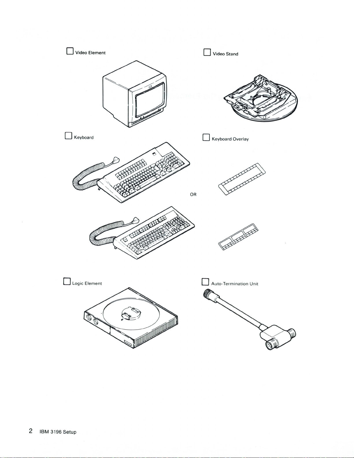
o Video
Element
o
Video
Stand
o Keyboard
o Logic
Element
o Keyboard Overlay
o
Auto-Termination
Unit
2 IBM 3196
Setup
Page 7
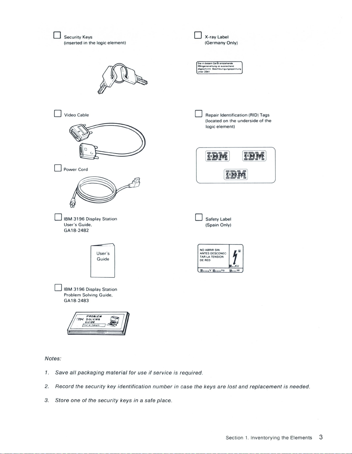
o
Security
(inserted
Keys
in
the
logic
element)
X-ray
o
(Germany
0,.
on
d,esem Gerlt enls'ehenOil
RiSnlgenSUlhlung
ebgesch"mt
unlet
20kV
Label
Only)
lSI
lu"eoc:hend
BescM.umgungs~nnu"9
o Video Cable
o
Power
Cord
o
IBM
3196
User
's
Guide
GA18-2482
Display
,
User's
Guide
Station
o Repair
(located on
logic
o
Safety
(Spain Only)
NOABRIR
SIN
ANTES OESCONEC·
TAR LA TENSION
OERED
(Il
••••
v
1E
••••
Identification
the
element)
Label
t~
!m
••
KV
Hz
1iI
•••
(RID) Tags
underside
[
!x~M
--_
W
of
the
l
.-
o
Notes:
1.
Save
2.
Record
3.
Store
IBM
3196
Display
the
Station
material
key
security
Problem Solving Guide ,
GA18-2483
all
packaging
the
security
one
of
for
use
identification
keys in a safe
if
service
number
place
is
required
,
in case the keys
.
are
lost
and
Section
replacement
1.
Inventorying
is needed.
the
Elements
3
Page 8

4 IBM 3196
Setup
Page 9

Section
2.
Setting Up the Display Station
Be sure you have met the installation requirements
and the
up
2.1
2.1.1 Turn the
IBM
5250
Information
your display station.
ATTACHING THE TAGS TO YOUR VIDEO ELEMENT, LOGIC ELEMENT, AND KEYBOARD
ELEMENT.
Note: IBM uses the
display
station. Without these tags,
logic
Display
Repair
element
System
Identification (RID) tags to
upside
down
Planning
service
.
of
may
the
and
IBM
Site
be
delayed
3196
Display
Planning
determine
or
Station
Guide
, GA21-9337, before seHing
the
maintenance
unobtainable
Description
status of
.
, GA18-2481,
your
Section 2.
Setting
Up
the
Display
Station 5
Page 10
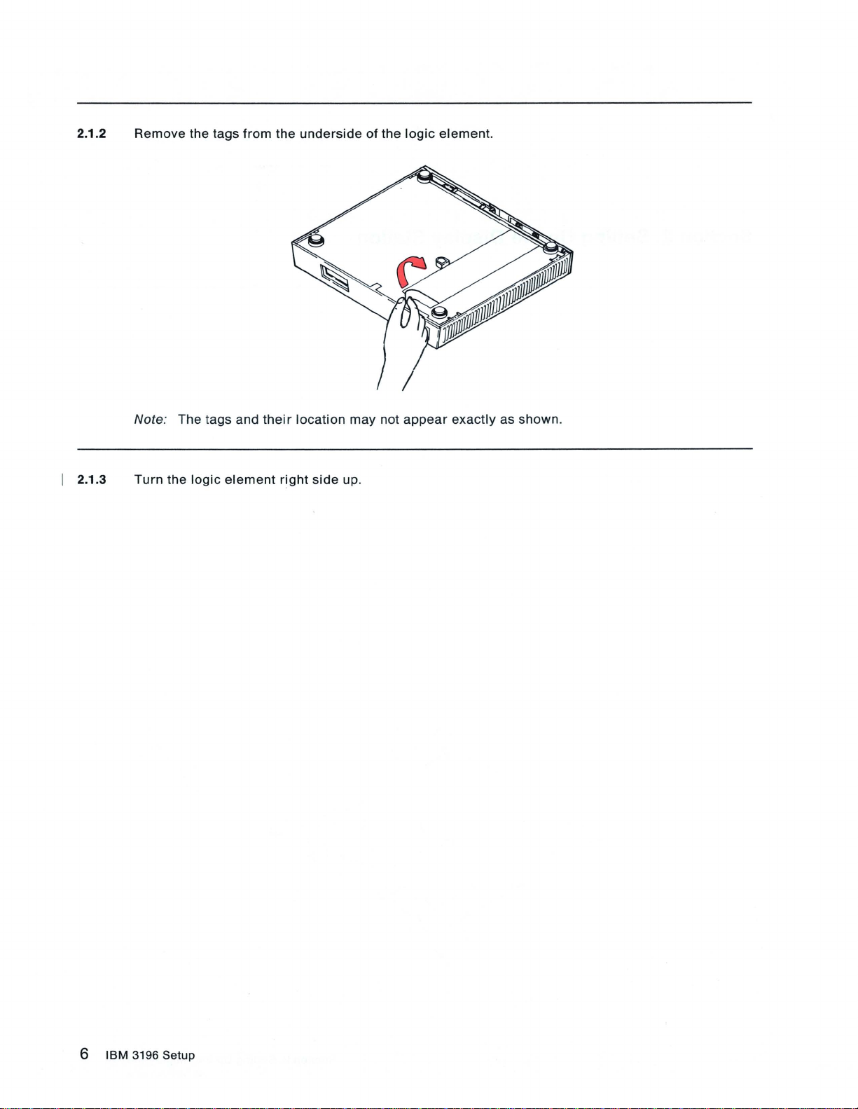
2.1.2
Remove
the tags
from
the
underside
of
the
logic
element.
I 2.1.3
Note: The tags and
Turn
the
logic
element
their
right
location
side
may
up.
not
appear exactly
as
shown
.
6
IBM
3196 Setup
Page 11
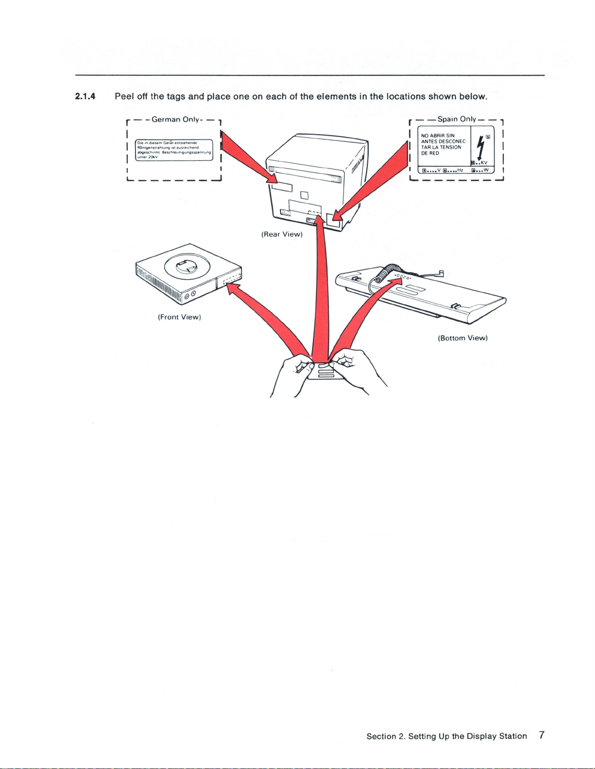
2.1.4 Peel off the tags and
r - -
German
Ole In
d.esem
Fl
ontvenst,"h1u"i '51
,
bgesch
..
unle.2010.V
I I
______
L
Only.
Ger;;1 enlSlflFlende
lIu5.e,Chend
ml B
eschleun
''iIun'ilSSOllnnu
(Front View )
place
one on each of the
- ,
ng
...J
elements
in
the
locations
r -
I NO A
~;~
I
I DE
I
1IJ ....
shown
-Spain
RED
below.
Only-
- ,
BRI
R SIN f
~~~~7o'::'
v
1iI
....
C
H'
ill
.
..
KV
1il ... W ,
I...------~
(Bo
ttom
View)
I
I
I
Section
2.
Setting
Up
the
Display
Station
7
Page 12

2.2 ATTACHING THE VIDEO STAND TO THE LOGIC ELEMENT.
2.2.1
Place the
align
circular
the notch
2.2.2 Pinch in the
two
portion
and
tab.
latches
to
of
lock
the
video
the
stand
video
in
stand
the
into
circular
the
logic
recess on
element
top
of the
; then
logic
release
element,
the
latches.
and
8 IBM 3196
Setup
Page 13
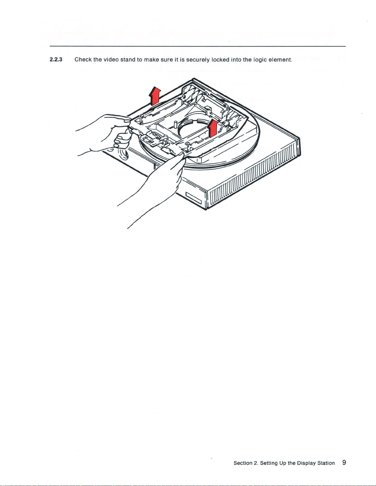
2.2.3 Check the
video
stand to make sure
it
is
securely
locked into the
logic
element.
Section
2.
Setting
Up
the
Display
Station 9
Page 14
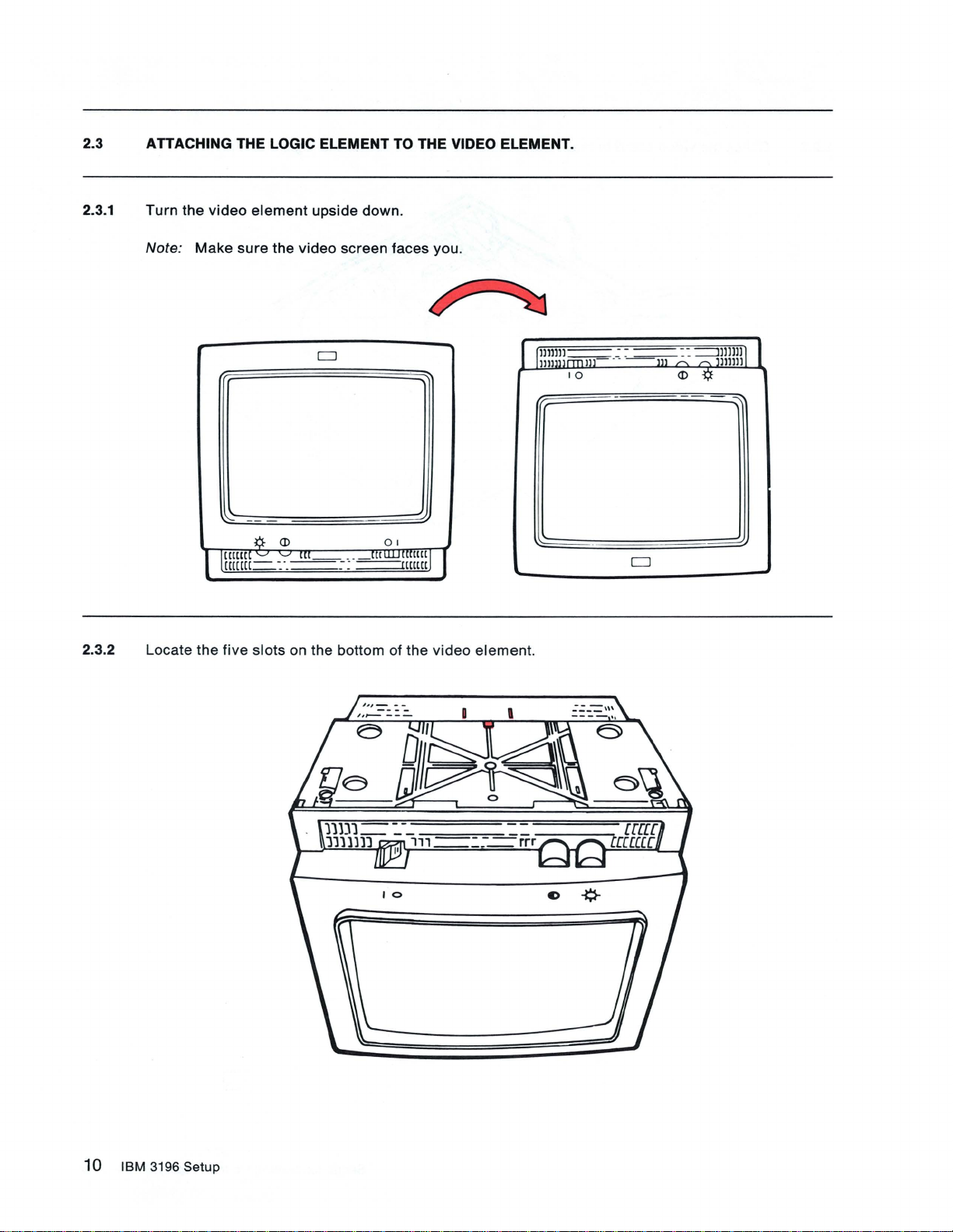
2.3 ATTACHING THE LOGIC ELEMENT TO THE VIDEO ELEMENT.
2.3.1
Turn
Note:
the
Make
video
1
2.3.2 Locate the
sure
([[UU
[[(([(1-
five
element
¢-
'J 'J
slots
upside down.
the
video
screen faces you.
CJ
<D
[[[-_
. .
: ..
-....:.:..:.--:~
on the bottom of the
_rr~[[[t([[
-=--rl([m
0 1
J
video
I
element.
lllllll~
1lI1111l1Il1LL
10
_ . .
~
~
--=:-
--m
'"
::
<D
==1
,-..
-l;f
lllllJ
J1Illll
1
10
IBM
3196
Setup
Page 15
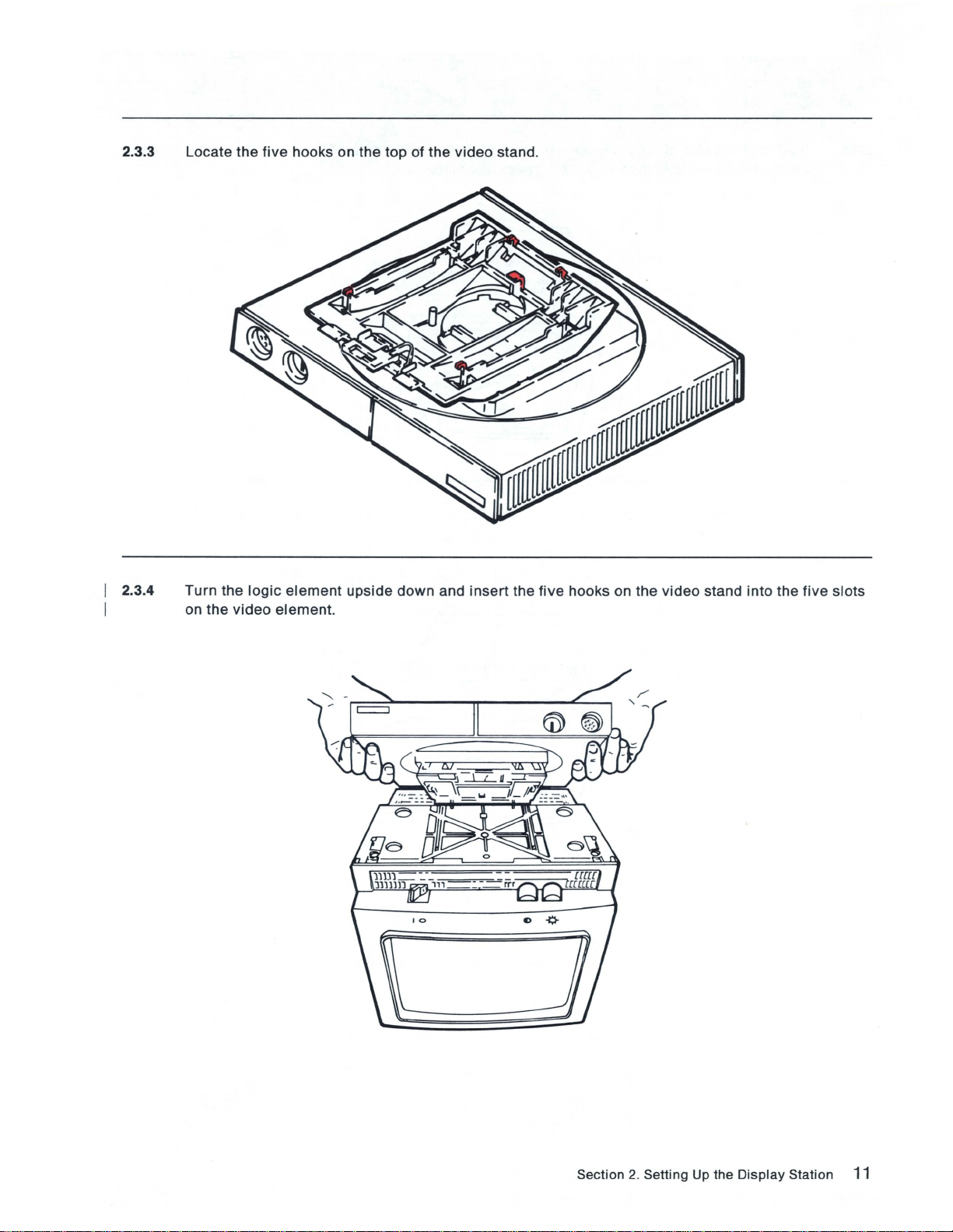
2.3.3 Locate
the
five
hooks on
the top
of
the
video
stand.
2.3.4
Turn
on
the
the
video
logic
element
element.
upside
down
and
insert
the
five
hooks
on
the
video
stand
into
the
five
slots
Section
2.
Setting Up
the
Display
Station
11
Page 16
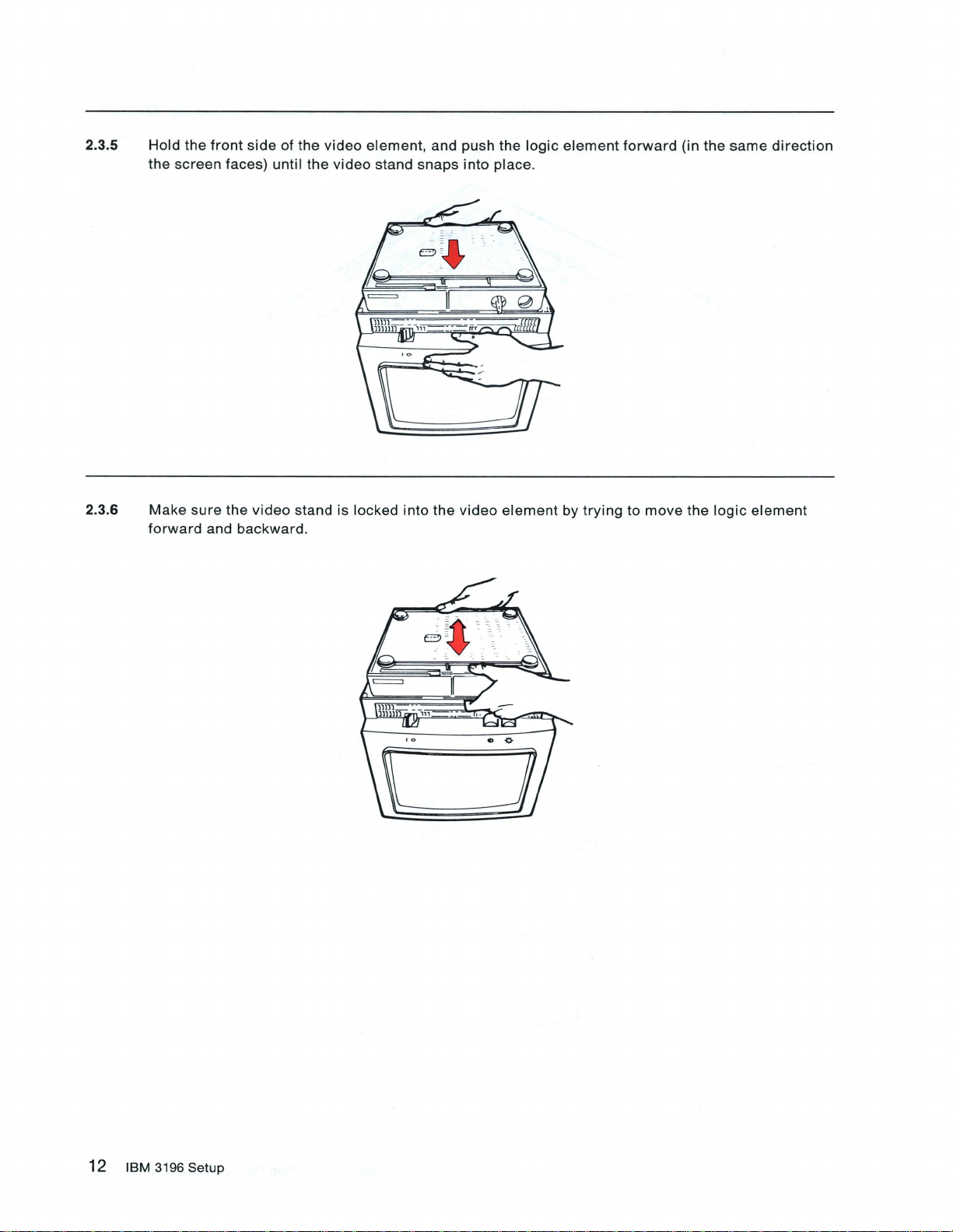
2.3.5 Hold
the
the
front
screen
side
of
faces) until
the
the
video
video
element,
stand
and push the
snaps
into
logic
place.
element
forward
(in
the
same
direction
2.3.6
Make
sure
forward
the
and
backward.
video
stand is locked into the
video
element
by
trying
to
move
the
logic
element
12
IBM
3196
Setup
Page 17

2.3.7
Turn
the
video
element
right
o
side
up.
o
Section
2.
Setting Up the
Display
Station
13
Page 18

2.4 CONNECTING THE VIDEO AND KEYBOARD CABLES.
2.4.1
Insert
tighten
Note:
the
the
The
plug
screws
video
on the
.
cable
video
cable
is
permanently
into
the
socket
attached
on
to
the
some
video
video
element
elements.
and
the
logic
element,
then
2.4.2
Remove
then
insert
Note:
Your
the
cap
the
keyboard
from
plug
the keyboard
into
the
socket
may
be
cable
on the
different
plug,
hold
front
of the
in
appearance
the plug
logic
element.
from
so
the
that
one
the
shown
IBM
.
logo
is facing up,
14
IBM
3196
Setup
Page 19

2.5 PREPARING THE DISPLAY STATION FOR POWER-ON.
2.5.1
2.5.2
Make
Insert
sure
the
that
power
the
cord
power
plug
switch
into
the
is
set
power
to
off
(0).
socket
on
the
rear
of
the
video
element.
Section
2.
Setting
Up
the
Display
Station
15
Page 20

SAFETY PRECAUTION
An
improperly
station. The
this
display
power
cord
responsible
If It
becomes
made
according
representative.
wired
outlet
power
station and
and
for
cord
plug
must
the
outlet
necessary
to
local
or
and
meet
be
and
to
change
or
national
plug
can
plug
(when
the
necessary
connected
plug
wiring.
power
code. A
place
hazardous
supplied)
testing
to a
properly
cord
new
voltages
on
your
display
laboratoryltest-house
wired
and
or
plug
or
if
the
power
cord
may
on
accessible
station have
grounded
outlet
is
be
ordered
metal
been
standards.
outlet. The
improperly
from
parts
approved
For
customer
wired,
your
IBM
of
your
have
sales
this
display
for
use
with
safety, the
is
the
change
Notice For
(9.2 tt),
tt)
(5.9
Customers
are
shipped
power
cord
2.5.3 Plug the
2.5.4 Make
sure
in
with
.
power
the
Chicago,
the IBM 3196
cord
security
Illinois:
into a grounded
key
Display
is
inserted
Two
different
Station. Do not use the 2.8 m (9.2 ft)
electrical
in
the
lengths of
outlet.
keylock
and
power
turned
cords, 1.8 m (5.9 ft) and 2.8 m
power
cord; use a 1.8 m
clockwise.
16
IBM
3196 Setup
Page 21

2.6 DISPLAY STATION POWER ON AND ADJUSTMENTS.
2.6.1
Adjust
To
adjust
from
To
adjust
your
the
the
underside
the
keyboard
keyboard
of
keyboard
to
to
the
to
the
desired
the
higher
keyboard
the
lower
slope
position,
.
position
(higher
turn
, push
or
the
the
lower
position).
keyboard
legs
into
upside
the
underside
down
and
of
flip
the
the
legs
keyboard
up
.
Section
2.
Sett
ing Up
the
Display
Station
17
Page 22

2.6.2 Place
the
keyboard
overlay
on
your
keyboard.
18
IBM
3196 Setup
Page 23

2.6.3
Press
and
hold
the
space
bar
and
set
the
power
switch
to
on (I).
Note:
Your
Continue
J" h
91111111
]1428
.t:lEtllll
9111 1
111
l'-stU'Nwyz'Lei()"n'f~'"'II
)JICL~liuW'I
---
---
-I
0
0000
0000000000000
0000000000000
00000000000
0
0000000000
0
0 0
keyboard
holding
..
.u("'.«·IWhi;
'
:.r·=
00000000
0
may
be
the
space
bar
;,;
r."·I;~·
..
-e.b<Mf~,n~
'
SHJ'tWXTZ1ODOOO912.Jo45tt7WiA.Uj
0
~:
: '
Jklenop
-'''
.tAlCIJ(F~I·6oOOa
000
0000
000
0000
000
0000
0000
0
00
000
different
until
.%f
'
..
r •••
••
in
appearance
one
of
the
following
from
the
displays
Jl'lb
18111111
lel111
00
00 0 000000000000
00 0 0000000000000
00 0 00000000000
00
one
shown.
appears.
!.UU(M
,
«tIW
,d;
;·P·=
-a.b(~f~,
., OiD"
uuuv )
j,
U·,~.~~tll
TUVW)('1
0
0
.ttEtllll
,.,
tUyw.yl
IJl(ll'KPOAlu
'
1'
-I
000000000000
000000000000
0000000000000
0 0 0 0 0 0
i
6'''I;-·/~
n~:' J~I
-···
_IAI(D(F~I'60006
'0D00091
2J.4~7
000
0000
000
0000
0
0000
000
0000
00
:.%.)'
.......
rtl
••
8ct3l.tDj
' •
TEST
Note: This
If
correct
GA18-2483.
Continue
the
powered
set
.
correct
display
with
"AD"
on
display
still
the
error
since
does
does
setup
0 0 0
code
is
normal
being
shipped
not appear,
not appear,
instructions.
if
from
set
refer
this
the
to
is
the
IBM.
power
the
IBM
TE
ST
first
It
will
switch
3196
time
reset
to off
Display
Section
that
the
when the
(0),
2.
Setting
display
and
Station
station
display
repeat
Problem
Up
the
has
station
step
Solving
Display
o
00
been
address
2.6.3. If the
Guide,
Station 19
is
Page 24

2.6.4
Adjust
the
video
element
to
the
desired
viewing
position.
To rotate
edge
and
tilt
the
To
element
the
video
element,
turn
it left
or
right.
video
element, place
as shown above.
place
Then
your
your
pull
hands on both
hands on
upward
or
the
push
sides
upper
back
downward.
of
the
edge
video
and
element
front
edge of the
near
the
front
video
20
IBM
3196
Setup
Page 25

2.6.5
Adjust
To
increase
To
decrease
the
screen
the
the
brightness
screen
screen
to a comfortable
brightness,
brightness,
turn
turn
the
brightness
the
brightness
viewing
level.
control
control
clockwise
counterclockwise
.
.
2.6.6
Adjust
To
increase
To
decrease
the
screen
the
screen
the
~L
contrast
screen
to a comfortable
contrast,
contrast, turn
turn
~l
[[[
the
the
viewing
contrast
contrast
- -
_[[C
level.
control
control
Jj
clockwise
counterclockwise.
.
~
'-.::.":[[.::.:[
==--= - -
-([[
Section
2.
Setting
Up
the
Display
Station
21
Page 26

22 IBM 3196
Setup
Page 27

Section 3. Display Station Configurations
Before
D
entering
The
to
is
Note: If
you
before
D You
3196 and
to the
workstation
workstations
Some Important Points to
• When you
•
up and
that
Do
will
not
they
attempt
the
display
system
set
up and
you
may
be
the
workstation
have a floor
any
system
station
or
workstation
operating.
are
connecting
setting
plan
other
or
remote
(display
are
connected
Remember
have
more
than one
will
be connected
be
connected
to
directly
set up
address, make
controller
your
display
up
the
workstations
controller
identifying
workstation
workstation
station and
is
the
(display
printer)
together
About Setup
workstation
together, always
to
the
system
more
than one
sure
you
are
station
(display
set
up and
location
station
controller.
must
.
(display
begin
or
workstation
workstation
that:
connecting
to
a 5294
stations
operating.
and
address
or
printer)
The
address
be
different
station
at a time.
with
or
the
controller
your
IBM 3196
Control
and
printers)
of
your
IBM
that
connects
for
each
when
printer)
workstation
to
.
Unit,
set
Section
3.
Display
Station
Configurations
23
Page 28

3.1
ENTERING YOUR DISPLAY STATION ADDRESS, KEYBOARD ID, AND MULTINATIONAL
CHARACTER SET.
3.1.1 Refer
cover
Note: Each
workstations
3.1.2
Determine
to
of
your
the
floor
plan and find
IBM
3196
Display
workstation
are
connected together.
which
keyboard you
Station
address
your
display
Problem
(for each
are
using. Does
station
Solving
display
your
address, then
Guide.
station
and
keyboard
record
printer)
Record
look
must
like
the
this
address
be
different
your
address here!
one?
on the
when
front
You
keyboard
Go
24 IBM 3196 Setup
YES NO
have
the
122-key You have the
•
to step
.
3.1
.3. Go
keyboard
•
to
step
.
3.1
t02-key
.10.
Page 29

3.1.3 Press
the
SetUp key.
blinking
A
3.1.4 Press and
6)
you
previously
GA 18-2483,
diamond
hold
the Set
recorded
appears
appears
Address
to
the
at the bottom of the
EXAMPLE
(Cmd24) key until
on
the
front
of
your
right
of
the
blinking
EXAMPLE
display
o
the
display
IBM
3196
diamond
screen.
station
Display
at the bottom of
address
Station
(a
Problem
your
display
number 0 through
Solving
Guide,
screen
.
Note: If 9012
o 1
---------------
appears
on the bottom of
the
display
~
screen,
Section
----
repeat
step
3.
Display
3.1.4.
Station
Configurations
25
Page 30

3.1.5 Open the
Problem
door
on
Solving
the
right-front of
Guide, GA18-2483, in the
the
logic
element
compartment.
and store
Then
/ ,
the
IBM
close
3196
the
door
Display
.
Station
26
I
BM
3196 Setup
Page 31

3.1.6
Make
of
your
sure
display
that
the
keyboard
screen)
is
a"-
10
displayed
_If.
to the
EXAMPLE
right
of
the
display
station
address
(at
the
bottom
If
the
displayed
appears
Keyboard
beside
10 key
keyboard
the
display
is
pressed
10
is
station
.
00
through
address. A "- _
63,
press
o 1
Keyboard
Sample
the
Keyboard
If
immediately
--
10
Only
10 (Cmd23) key until a "- _
follows
the
number
63
when
If
the
Section
3.
Display
Station
Configurations
27
Page 32

3.1.7 Do you
want
to
select
the
multinational
character
set?
Go to
Note: The
multinational
3.1.8 Press the
character
YES
step
3.1.8
•
Multinational
character
Multinational
set.
Character
set
unless you
Character
NO
Go to
step
3.1.9.
•
Set is a function of
consult
Set (Cmd 22) key to
your
system
your
host system. Do
operator
alternately
not
.
enable/disable
select
the
the
multinational
When an
multinational
"M"
appears
character
to
the
set
is enabled.
right
of the
blinking
diamond
EXAMPLE
at
the bottom of
o M 1
your
display
screen
, the
28
IBM
3196 Setup
Page 33

3.1.9 Press
The
display
switch
Go
the
SetUp key.
is
set
to
Section
station
to
off
options
(0).
4.
are
Connecting
now
set
and
will
not be
changed
to
a Host System or a Controller.
even
if
the
display
station
power
Section
3.
Display
Station
Configurations 29
Page 34

3.1.10 Press and
hold
a Shift key, then
press
the
SetUp key .
blinking
A
diamond
appears
at
the
bottom of
the
display
EXAMPLE
o
screen
.
30
IBM
3196
Setup
Page 35

3.1.11 Press and
address
Station
bottom of
(a
Problem
hold
a Shift key, then
number 0 through
your
Solving
display
Guide, GA18-2483,
screen
press
the
Set
Address
6)
you
previously
.
recorded
appears
EXAMPLE
key (F24/F12)
to the
o
on the
right
front
of
the
until
of
your
blinking
the
display
IBM
3196
diamond
station
Display
at
the
3.1.12
Note: If 9012
Open
the
door
Problem
Solving
appears
on the
on the bottom of
right-front
Guide, GA 18-2483, in
of the
the
display
logic
element
the
compartment.
screen, repeat step 3.1.11 .
and
store
the
Then
IBM3196
close
the
Display
door.
Station
Section
3.
Display
Station
Configurations
31
Page 36

3.1.13
Make
of
your
sure
display
that
the
keyboard
screen) is a 00.
10
displayed
to
the
right
of
the
EXAMPLE
display
station
address
(at
the
bottom
If
(F23/F11) key until a
number
3.1.14 Do
the
displayed
you
31
when
want
----
10
is
01
through
00
appears
the
Keyboard
to
select
the
YES NO
31,
press
beside
10
key
Multinational
the
is
pressed
Character
and
display
o
hold
a Shift key, then
station
.'
Set?
00
.
Keyboard ID
Only
Sample
press
address. A
the
Keyboard
00
immediately
ID
follows
the
Go to step 3.1.15.
Note:
The
multinational
32 IBM 3196 Setup
•
Multinational
character
Character
set
unless
step
3.1.
Go to
Set is a function of
you
•
consult
16.
your
your
system
host
system.
operator.
Do not
select
the
Page 37

3.1.15 Press and
enable/disable
hold
a Shift key, then
the
multinational
press
the
character
Multinational
set.
Character
Set (F22/F10) key
to
alternately
When an
multinational
"M"
appears
character
to the
set
right
of the
blinking
is
enabled
.
EXAMPLE
diamond
o M 1
at
the
bottom of
your
display
screen, the
Section
3.
Display
Station
Configurations
33
Page 38

3.1.16 Press and
The
display
switch
Go
is
to
Section
hold
a Shift key, then press the SetUp key.
station
set
to off
options
(0)
4.
are
.
Connecting
now
set and
will
not be changed even if the
to
a Host System or a Controller.
display
station
power
34
IBM
3196
Setup
Page 39

Section
4.
Connecting
to
a Host System or a Controller .
4.1
4.1.1
BEFORE YOU CONNECT YOUR DISPLAY STATION TO A HOST SYSTEM OR A REMOTE
WORKSTATION CONTROLLER, REVIEW YOUR FLOOR
SAFETY PRECAUTION
Do not connect or disconnect cables during an electrical storm. You could
Do
the
following.
1.
Set
the
power
2.
Disconnect
switch
the
power
to
cord
off
(0)
~
.
from
the
.>'
power
outlet.
PLAN.
be
seriously injured.
Section
4.
Connecting
to a Host
System
or a Controller
35
Page 40

4.1.2
Align
rear
until
the
of
the
tight.
widest
logic
slot
in the plug on
element.
CAUTION
Never
connect the communications cable directly
connect the communications
the
auto-termination
Then push the plug
cable
to
the auto-termination unit.
into
unit
cable
with
the key in
the
socket
to
and
turn
the
retai
ning
your display station. Always
socket
ring
on
the
clockwise
4.1.3
4.1.4
Locate
workstation
Align
Then
the
the
push
widest
correct
the
communications
controller, or
slot
in the
plug
into
the
the
previous
cable
socket
cable. This
workstation.
plug
with
and
turn
may
the key in
the
retaining
be the
either
cable
socket
ring
from
of
the
clockwise
the
host system,
auto-termination
until tight.
the
unit.
36
IBM
3196
Setup
Page 41

4.1.5 Refer
immediately
to
your
floor
before
plan. Is
your
IBM
there a workstation
3196?
(display
station
or
printer)
on the
cable
HOST
SYSTEM
L...-------------------Example
Go to
4.1.6
Connect
IBM 3196.
the
communications
WORKSTATION
BEFORE YOUR DISPLAY
YES NO
step
4.1.6.
Go to step 4.1.9.
•
cable
to
the
IMMEDIATELY
STATION
•
unused
port
Only
-----------------'
on the
workstation
YOUR DISPLAY
STATION
immediately
before
your
4.1.7 Does
locations
the
workstation
of
Go to
immediately
terminator
YES
step
•
switches.)
4.1.8. Go to step
before
yours
have a
NO
4.1
.9.
•
terminator
switch? (See
Appendix A for
Section
4.
Connecting to a Host System or a Controller 37
Page 42

· 4.1.8
Make
sure
Appendix A
that the
for
terminator
the locations of the
switch on the
terminator
workstation
switches.
immediately
before
yours
is set
to
2.
See
4.1.9
Will the
controller)
.......
communication
CONTROL
5294
UNIT
______________
Go to step 4.1.14.
cable (the cable that connects to the system
be connected to a 5294 Control Unit?
WORKSTATIONS
COMMUNICATION
CABLE
Example Only
YES
•
Make
communication
connected to the host
system, then go to step
4.1.10.
NO
sure
the
•
OTHER
cable is
YOUR
______________
or
the remote workstation
DISPLAY
STATION
~
4.1.10 Do the
1.
Connect
2.
Set the 3196
38
IBM
3196
following
Setup
the
.
3196
power
power
switch
cord to a grounded electrical outlet.
to
on (I).
Page 43

4.1.11
Notify
your
host
system
operator
that
your
display
station
is connected.
4.1.12
Note: You
initial
program
System/38
Does a sign-on
Enter password to
sigo
Cursor
cannot
.
on:
System/38
YES
proceed
load
(IPL)
display
to
for
the
(similar
the
to
next
IBM
one
step
until
System/36
of
the
two
2/2
NO
your
host system
or
performed
shown
Help-Assistance
operator
reconfiguration
below) appear?
User
ID
Password ...
User
menu .....•
libra
ry
..
' . ...•....
for
5190
on
System/36
has
performed
for
the
COPYRIGHT
Optional-*
1984
S
IGN
ON
••
.•
IBM
IBH
Corporation.
an
WI
06/56
Go to
step
4.1.14.
•
Go
to
step
4.1.13.
•
Section
4. Connecting
to a Host
System
or a Controller
39
Page 44

4.1.13
1.
2.
3.
Ask
the
a.
Check
operating
b.
Check
Note:
cabled
correct
Set
the
power
display
fastened .
If
it
(See
station
there
is a workstation
has a
Appendix
person
terminator
responsible
that
the
and
that
your
Your
display
together
address.
switch
are
A in
for
system
is
. If so,
connected
switch, make
this
able
to
display
may
to
off
on
guide
to
which
recognize
station
be on a
check
(0).
the
system
that
Then
to
the
cable
sure
for
the
operation
your
display
your
display
has
the
correct
cable
where
each
workstation on
make
sure
correct
immediately
sockets and
that
the
locations
to:
station
station.
address.
multiple
that
the
before
terminator
of the
terminator
is
connected
workstations
your
cable
cables
are
securely
your
switch
on
IBM
is
switches.)
is
are
has
the
your
3196 and
set
to
2.
4. Set
5. Do
YES NO
Go
to
step 4.1.14. Go to
the
the
•
power
conditions
switch
Display
Solving
GA18-2483.
to
on (I) .
in step 4.1.12
the
IBM
Station
Guide
3196
Problem
,
•
occur
now?
40
IBM
3196
Setup
Page 45

4.1.14
Refer
connect
Go
to
to
your
floor
plan
. Do
you
to
this
display
YES NO
step 4.1.15.
station?
Go
to
•
have
another
step
4.1.17.
•
workstation
(display
station
or
printer)
to
4.1.15
4.1.16
Set
the
outlet.
Connect
of
this
cable
3196
the
power
second
will
connect
switch
cable
to off
to
to
the
the
(0)
and
unused
next
workstation
disconnect
port
of
the
on
the
3196
power
auto-termination
this
cable
.
cord
unit.
from
The
the
other
power
end
4.1.17
CAUTION
When a
3196
unless
Connect
second
is
automatically
the
the
other
3196
cable
end
power
is
attached
unterminated.
is
connected
cord
to a grounded
Section
to
the
auto-termination
Do
not
connect
to
another
electrical
4.
Connecting to a Host System or a Controller
workstation.
outlet.
the
unit,
second
your
cable
IBM
41
Page 46

4.1.18
Setup
is
complete
to
a 5294 Control Unit,
on
this
go
display
to
the
station. If
IBM
5294
the
communication
Control
Unit Setup Procedure, GA21-9369.
cable
will be connected
42
Page 47

Appendix
The
following
A.
Location
illustrations
show
of
Terminator Switches
the
location
of
the
terminator
switch
on
display
stations.
Note:
Some
display
stations
do
not have a
5251 (Models 1 a
5291 (Mode l 1)
52
91
(Model 2)
terminator
nd
11)
switch
---
.
5292
(Models 1 and
2)
Appendix
A.
Location
of
Terminator
Switches
43
Page 48

The
following
illustrations
show
5219
the
location
of
the
terminator
switch
on printers.
~--
5224
5225
!lei
I
----
44
~~
5256
Page 49

IBM
3196
Setup
Publication
This
and
publication,
distribute
obligation
Instructions
manual
operators
Display
No.
GA
is part
of
IBM
its
organization,
whatever
to
you
.
Station
18-2488-2
of
a library
systems.
information
that
You
or
subject
you
serves as a reference
may
use
this
form
matter,
supply
in
with
any
the
way
source
to
understanding
it
believes
for
communicate
appropriate
systems analysts,
your
comments
that
IBM
may
without
READER'S
COMMENT
FORM
programmers,
about
this
use
or
incurring
any
Note:
Please
your
IBM
Possible
Clarity
If
you
wish
Copies
direct
of I BM
any
representative
topics
for
Accuracy
a reply,
publications
requests
comment
give
are
for
copies
or
to
the
IBM
are:
Completeness
your
name,
company, mailing
not
stocked
of
publications, or
branch
office
Organization
at
the
location
for
assistance in
serving
your
Coding
address, and date:
to
which
locality.
this
using
Retrieval
form
your
is
addressed .
IBM
system,
Legibility
to
What
is
Number
Thank
an I
BM
to
the
your
occupation?
of
latest
you
for
your
office
or
address in
------------------------------------------------
Newsletter
cooperation. No
representative
the
Edition
associated
Notice
will
with
postage
be
happy
on
the
this
stamp
to
back
publication
necessary
forward
of
the
title
:
your
page
if
mailed
comments
.)
in
the
U.S .A. (Elsewhere,
or
you
may
mail
directly
Page 50

GA
18-2488-2
Reader's
Fold
...........
Comment
and
tape
......
Form
.. .......... ..
Please
...
Do
.....
Not
Staple
...
........
. ·
1111
·1····
Fold
and
·····
tape
~1~!~~ij
IN
THE
UNITED STATES
....
.
...
. ....
Fold
--..-
----
---~
--
~
--
-----
-----
..........
and
tape
--
---
---
BUSINESS
FIRST CLASS PERMIT NO. 40 ARMONK, N.Y.
POSTAGE
International Business
Dept.
180
Mechanicsburg, PA
WILL
6R1
J
Kost Road
.
........
REPLY
BE
PAID
17055
. , .
.........
Please
BY
ADDRESSEE
Machines
Do
-
,
®
MAIL
Corporation
......
Not
Staple
. .
...
. .
...
. ......
.....
Fold
. ....
and
tape
..
'
..
. . . .
Page 51

Page 52

GA
18-2488-2
Part Number
File Number
81
X537
S5250/36/38-06
4
----
----
- -
---
- -
- - -
-----
--_
---
---
---
.-
GA
18-2488
-2
 Loading...