

Page 1
I
----
----
- -
---
---
- -
- -- ---
-----
--_
---
.-
File No. S370/303X/308X/309X/4300/81
IBM
ASCII Display Station
3151
00
User's Guide
/S1-09
81X4495
for the Cartridge
IBM
and DEC' Terminals
to
Emulate
GA
18-2654-0
Page 2

---------
•
----
----
- -
---
-
-.
- --
-----
---,-
---
---
---
File
No. S370/303X/308X/309X/4300/8100/S1-09
IBM
ASCII
3151
Display
Station
•
••
User's
for
IBM
the
and
Guide
Cartridge
DEC!
Terminals
to
Emulate
81X4495
GA
18':2654-0
Page 3

FEDERAL COMMUNICATIONS COMMISSION (FCC)
in
STATEMENT (Applies only to those machines used
the U.S.)
Warning: This equipment generates, uses, and can radiate radio
if
frequency energy and
not installed and used in accordance with the
instruction manual, may cause interference to radio communications.
It
has been tested and found to comply with the limits for a Class A
computing device pursuant to
Subpart J
of
Part
15
of
FCC Rules,
which are designed to provide reasonable protection against such
interference when operated in a commercial environment. Operation
of
this equipment in a residential area
at
which case the user
whatever measures may
his own expense will be required to take
be
required to correct the interference.
is
likely to cause interference in
First Edition (April 1987)
Changes are made periodically to the information herein; any such changes will be
reported in subsequent revisions
or
Technical Newsletters.
References in this publication to IBM products, programs,
IBM intends to make these available in all countries in which IBM operates. Any.
reference
that only IBM's program product may be used. Any functionally equivalent program
may be
Publications are
should
locality,
A form for reader's comments
been removed, comments may be addressed to IBM Corporation, Publications
Development,
may use
without incurring any obligation
lTrademark
© Copyright International Business Machines Corporation
to
an
IBM program product in this publication
used instead.
not
stocked
at
be
made to your IBM representative, to the IBM branch office serving your
or
to the place
DepartmeBt..6RlJ,
or
distribute whatever information you supply in any way
of
Digital Equipment Corporation
the address given below. Requests for IBM pUblications
of
purchase.
is
provided
180
to you.
at
the back
Kost Road, Mechanicsburg.
or
services
is
not
intended to state
of
this publication.
1987
do
not
·imply
or
If
the form has
PA
17055
it
U.S.A. IBM
believes appropriate
that
imply
Page 4

Using This Guide
•
Using This GUide
•
The "3151 cartridge to emulate IBM and DEC terminals"
3151
Models 31/41 and it is intended to provide enhancements to the base
machine.
This cartridge supports:
• The EIA RS-422A interface (available in all modes that this cartridge
supports)
• Emulation mode (mode to emulate the
Note: The DEC VT220 is a product
• The system attachment mode (hereinafter referred to
mode)
The IBM
the IBM 3710 Network Controller.
• The IBM
• The IBM
• Ten ASCII terminals' emulation modes
3151
can be attached to the IBM
3101
emulation mode
3151
native mode
DEC
VT220)
of
Digital Equipment Corporation .
3701
is
available for IBM
as
SYSTEM
Network Conversion Unit
ATTACH
or
•
- ADM2-3A
- ADM-5
ADDS3
Hazeltine
TeleVideos Model
- TeleVideo Model
- TeleVideo Model
Viewpoint-A2
4
1500
910
910
912
+
Using This Guide III
Page 5

Using This Guide
TeleVideo Model 920
TeleVideo Model 925
TeleVideo Model 925E.
This
guide provides information
about
the:
• Emulation mode (mode to emulate the
DEC
• SYSTEM ATTACH mode.
This guide is intended for customers who will use:
•
DEC
system
•
IBM system
• Both IBM and
This guide does
3101
emulation mode,
information
in
the mode to emulate the
DEC
systems.
not
include information for the IBM
or
the ten ASCII terminals' emulation modes.
on
these modes, refer
to
IBM
DEC
3151
ASCII
Operations.
Note for customers
Interface parameter is added
the
3151
in neither SYSTEM
VT220, refer also to
who
use this cartridge
in
ATTACH
IBM
3151
to
select RS-422A
the
COMMUNICATION
mode
nor
ASCII
Display Station Guide to Operations when
defining setup values.
VT220)
VT220
3151
native mode, the
For
Display Station Guide
for
the interface: The
menu.
If
you
the mode to emulate the
IBM
to
operate
DEC
2 Registered trademark
of
Trademark
4 Trademark
Trademark
IV
User's Guide for the Cartridge to Emulate IBM and DEC Terminals
Applied Digital
of
Esprit Systems, Incorporated
of
TeleVideo Systems, Incorporated
of
Zentec Corporation
Data
Systems, Incorporated
Page 6

Related Publications
•
•
This guide has
• Chapter
DEC
SYSTEM
the latter, several differences between the mode to emulate the
and
• Chapter 2, "Setup Procedures" provides information for the setup procedures
in IBM mode as well as in the mode to emulate the
• Chapter
menus
• Chapter 4, "Interpreting Operator Messages" provides the information
needed to interpret operator messages
•
Chapter
necessary for the programmer who works with IBM mode
emulate the
five
1,
"Introducing the U.S. English Cartridge to Emulate IBM
Terminals" describes the two modes supported
ATTACH
the original terminal (the
3,
"Setup Menus
and
setup values.
5,
"Reference Information" provides the information
DEC
Related Publications
chapters:
mode
VT220.
by
this cartridge;
and
the mode
DEC
and
Setup Value Descriptions" describes the setup
to
emulate the
VT220 terminal) are described.
and
which actions
DEC
DEC
VT220.
to
take.
and
VT220.
DEC
that
the mode
and
For
VT220
is
that
to
is
•
•
DEC
VT220 Owner's Manual
•
DEC
VT220 Programmer Reference Manual
•
IBM
3151
ASCII
This guide explains how
introductory information
messages
emulations are described as well. The solving problems chapter is used
isolate failing elements.
•
IBM
3151
that
ASCII
Display Station Guide
to
install
and
explains the key functions, indicators,
are displayed
Display Station Reference Manual, GA18-2634-0
at
the
to
Operations, GA18-2633
and
set up the IBM 3151.
bottom
of
the screen.
The
It
Using This Guide V
also provides
and
built-in
to
Page 7

Related Publications
This guide provides information on the IBM
It
also introduces the IBM
use
how to
it.
3151
ASCII Display Station; what
3151
functions and commands.
it
can do and
VI
User's Guide for the Cartridge to Emulate IBM and DEC Terminals
Page 8

Contents
•
Contents
•
•
Chapter 1. Introducing the U.S. English Cartridge to Emulate
Terminals
Changing the Machine Mode
Machine Mode Switch Key
Describing the Mode to Emulate the DEC
Functions Supported Differently in Emulation Mode
Functions
Additional Functions in Emulation Mode
Additional Commands/Response in Emulation Mode
Additional Keyboard Functions in Emulation Mode
Describing SYSTEM ATTACH
Chapter
Setting
Setting
Defining Function Keys (emulation)
Setting Tab Stops (emulation)
Defining Function Keys (IBM Mode)
Chapter 3. Setup Menus and Setup Value Descriptions
Setup Menus and Setup Values (emulation)
Setup Menus and Setup Values (SYSTEM ATTACH)
Up
Up
GENERAL Menu (emulation)
DISPLAY Menu (emulation)
COMMUNICATION Menu (emulation)
KEYBOARD Menu (emulation)
PRINTER Menu (emulation)
IBM
FUNCTION Menu (emulation)
Equivalent Setup Parameters
Setup Parameters List (emulation)
GENERAL Menu (SYSTEM ATTACH)
1-1
1-2
1-3
Not
Supported in Emulation Mode
1-13
2.
Setup Procedures
the Display Station for This Cartridge
the
3151
4201
Proprinter or IBM
2-5
2-1
2-32
2-34
2-36
3-3
3-6
3-11
3-13
4202
Proprinter XL Connection 3-16
3-18
3-20
3-23
VT220
1-8
3-2
3-8
3-25
1-5
1-6
1-8
1-9
1-9
2-3
3-1
3-25
mM
and DEC
Contents Vll
Page 9

Contents
COMMUNICATION Menu (SYSTEM ATTACH)
KEYBOARDjPRINTER Menu (SYSTEM ATTACH)
FUNCTION Menu (SYSTEM ATTACH)
Setup Parameters List (SYSTEM ATTACH}
Setup Parameters List (IBM 3151/3101)
How to Define Setup Values
Selecting a Menu
Selecting a Field in the Menu
Selecting Values in the Fields
Saving the Definitions
Chapter
Chapter
Mode to Emulate the DEC
SYSTEM ATTACH Mode
4.
Interpreting Operator Messages
S.
Reference Information
Select Screen Format
Using the Select Screen Format Command
Using the Column Mode Command (DECCOLM)
Additional Commands and Response
Dynamically Re-definable Character Set
Designing Your D RCS Characters
Loading Your DRCS Characters
DEC
VT220
DRCS Character using the Whole Area
Host Commands
Set/Read Control I Commands/Response
Set/Read Control 2 Commands/Response
Set/Read Control 4 Commands/Response
Set/Read Control 5 Commands/Response
Set/Read Control 7 Commands/Response
Write Host Message Command
AID Codes and Keyboard Functions
Type DRCS Character
3-33
5-11
3-33
3-37
VT220
5-1
5-11
3-35
3-36
5-1
5-1
5-4
5-6
5-32
5-3
5-7
of
5-34
3-29
3-32
4-1
5-2
5-4
a Cell
5-12
5-16
5-20
5-22
5-28
3-27
3-28
3-30
5-3
5-8
Index X-I
Vlll User's Guide for the Cartridge to Emulate IBM and DEC Terminals
Page 10

•
•
•
Figures
1-1.
Functions Supported Differently in Emulation Mode
1-2.
Keyboard Layout to Emulate the DEC VT220
1-3.
Location
1-4.
Additional Keyboard Functions in Emulation Mode
2-1.
Key Caps
2-2.
Using the Key Caps and Overlay 2-4
2-3.
Keys Used for Defining Function Keys (emulation)
2-4.
Keys Used for Setting Tab Stops (emulation) 2-34
2-5.
Keys Used for Defining Function Keys (IBM Mode) 2-36
3-1.
GENERAL Menu (emulation)
3-2. Setup Parameters in the GENERAL Menu (emulation)
3-3.
DISPLAY Menu (emulation)
3-4.
Setup Parameters in the DISPLAY Menu (emulation)
3-5.
COMMUNICATION Menu (emulation)
3-6.
Setup Parameters in the COMMUNICATION Menu (emulation)
3-7.
KEYBOARD Menu (emulation)
Setup Parameters in the KEYBOARD Menu (emulation) 3-12
3-8.
3-9.
PRINTER Menu (emulation)
3-10.
3-11.
3-12.
3-13.
3-14.
3-15. Setup Parameters and Their Possible Values (emulation)
3-16.
3-17
3-18.
3-19.
3-20.
3-21. Setup Parameters and Their Possible Values (IBM
Setup Parameters in the PRINTER Menu (emulation) 3-14
Example
FUNCTION Menu (emulation)
Functions
Equivalent Setup Parameters (emulation)
GENERAL Menu (SYSTEM ATTACH)
. COMMUNICATION Menu (SYSTEM ATTACH) 3-27
KEYBOARD/PRINTER Menu (SYSTEM ATTACH)
FUNCTION Menu (SYSTEM ATTACH) 3-29
Setup Parameters and Their Possible Values (SYSTEM
ATTACH) 3-30
3101)
of
Additional Keys
2-3
of
the Proprinter (XL) Switch Settings 3-16
in
the FUNCTION Menu (emulation) 3-19
3-32
1-10
3-3
3-6
3-11
3-13
3-18
1-7
2-32
3-8
/
3-20
3-25
3151
Figures
1-6
1-10
3-4
3-7
3-9
3-23
3-28
and IBM
Figures
IX
Page 11

Figures
3-22.
Selecting a Menu (emulation)
3-23.
Selecting!a Menu (IBM Mode)
Selecting' a Field
3-24.
3-25.
Selecting Values
3-26.
Saving the Definitions (emulation)
Saving the Definitions (IBM Mode)
3-27.
4-1.
Operator Information Area
4-2.
Operator Messages
5-1.
Select Screen Format Parameters
Cell Used in the
5-2.
5-3.
Cell
Used in DEC
5-4.
DEC
VT220
5-5.
Designing a Musical Note
Column Definition in DEC
5-6.
5-7.
Column Definition and Musical Note in DRCS Character Using the
Whole Area
5-8.
AID Codes and Keyboard Functions
of a Cell
3-35
3-36
4-3
3151
Cell Area in the
5-4
VT220
5-8
(OIA)
5-5
3151
5-6
VT220
3-33
3-34
3-37
3-37
4-2
5-2
Cell
Type DRCS Character
5-5
5-34
(\
\. )
5-7
X User's Guide for the Cartridge to Emulate IBM and DEC Terminals
Page 12

Introduction
•
•
Chapter 1. Introducing the
Emulate
IBM and DEC Terminals
The "U.S. English cartridge to emulate IBM and DEC terminals" supports:
• The EIA RS-422A interface (available in all modes that this cartridge
supports)
• Emulation mode (mode to emulate the DEC VT220)
• SYSTEM
• The IBM
• The IBM
• Ten ASCII terminals' emulation modes.
This guide explains the:
• Emulation mode (mode to emulate the DEC VT220)
• SYSTEM
ATTACH mode
3101
emulation mode
3151
native mode
ATTACH mode .
U.S. English Cartridge to
•
Chapter
1.
Introducing the U.S. English Cartridge to Emulate IBM and DEC Terminals
1-1
Page 13
Introduction
Changing the Machine Mode
The machine
mode
IBM
can
be changed
3151
!
IBM
3101
!
ADM3A
!
ADM
5
!
ADDSVPA2
!
HZ1500
!
TVI910+
Machine modes
•
IBM
3151
•
IBM
3101
•
Ten
ASCII terminals
TVI910 + /910, TVI925E/925,
•
DEC
VT220 (VT220
• SYSTEM
ATTACH.
are
classified
/910
in
into
five groups:
(ADM
CONTROL
3A,
and
the
following
ADM
5,
ADDS
TVI920/912)
7/8, VT100,
order
in
the setup menu.
SYSTEM
ATTACH
t
VT52
t
VT100
t
VT100 CONTROL 7
t
VT200 CONTROL 8
t
TVI920/912
t
TVI925E/925
VP
A2,HZI500,
and
VT52)
When
the
(from VT52
3151
to
8
in
case
internal circuits) is performed.
setup menu, the setup
Note: The machine
command
1-2
User's Guide for the Cartridge
machine
IBM
of
using the setup menu), a power-on reset (except the checking
(see
to
SYSTEM
3101,
"Set/Read
mode
is changed
IBM
3101
menu
mode
to
Emulate IBM
to
a new machine
ATTACH,
for the new machine mode is then displayed.
can
Control
SYSTEM
to
ADM
3A,
When
the
also
be
changed
1 Commands/Response"
and
ATTACH
or
TVI920/912
machine mode
by
DEC Terminals
mode
in
to
IBM
to
VT200
group
using the Set
on
is changed
page 5-12).
a different
3151,
IBM
CONTROL
Control
group
of
in
1
the
the
Page 14

When
•
SYSTEM
mode
in
the setup menu, the new machine
you
select
function, the machine
'will
also be set
On
the
other
selected for the machine
saved
at
this point.
performing the Save function, the machine
machine
Instead,
be set.
case.
When
the machine
mode
the
You
you
ATTACH,
SYSTEM
to
hand,
will
latest saved machine mode for the
must
power-on the display station the first time with the cartridge inserted,
mode
• Machine Mode Switch Key
For
the customers
the
support
machine
CONTROL
versa.
pressed while holding
Machine
Machine
for a Machine Mode Switch function
mode
from
8)
to
The
Machine
Mode
Switch key). See Figure
Mode
Switch key.
IBM
3151,
or
IBM
3101 is selected for
mode
is immediately saved.
ATTACH
mode
SYSTEM
when one
mode
That
not
be set to VT100 the next time power is turned on.
perform
is
~t
to
who
use
DEC
IBM
(IBM 3151,
Mode
down
and
exit setup
is set
to
SYSTEM
ATTACH
of
the
ten
in
the setup menu, the new machine
is,
if
you
select VT100
the Save function
VT200
both
(VT52, VT100, VT200
Switch function is performed when the Send key is
the
Control
IBM
IBM
etrl
and
and
menu
without performing the Save
ATTACH.
the next time power is
ASCII
terminals
and
mode
is set
DEC
to
save the machine
7.
DEC
systems, this cartridge provides
that
CONTROL
3101,
or
SYSTEM
Shi/{ keys (hereinafter referred
1-3
pn
page 1-10 for the location
The
or
the
exit setup
to
VT100. However, the
VT220 machine
allows
ATTACH)
Introduction
the
machine
That'is,
machine
turned
DEC
menu
you
7,
mode
to
or
mode
on.
VT220 is
mode
is
not
without
group
will
in
this
switch the
VT200
and
to
as
of
if
vice
the
•
To
1.
2.
Chapter
use the Machine
Select the machine
VT200
Setup Values (emulation)"
Select the machine
IBM
(IBM
1.
CONTROL
3101,
Mode)"
Introducing the U.S. English Cartridge to Emulate IBM and DEC Terminals
Mode
or
SYSTEM
on
Switch key, the following setup is peeded:
mode
and
define the setup values for
7,
or
VT200
mode
and
ATTACH).
page 2-29 for
CONTROL
on
page 2-26 for more information.)
define the setup values for
(See
more
information.)
8). (See
"Step
12B. Defining Setup Values
DEC
"Step
IBM
(VT52, VT100,
12A. Defining
(IBM
3151,
1-3
Page 15

Introduction
Note: When
that
you
enter the setup menu
is IBM
from-IBM
If
you enter the setup menu
the machine mode changes as described
page
1-2
menu.
Changing the Mode between
In
daily operation, you
SYSTEM ATTACH to VT100
Mode
Switch key as follows:
1.
Sign
2.
Press the Send key while holding down the Ctrl
Mode
3.
Sign
you
fIrst set the machine mode
and
you
to
DEC
and
IBM
off
the current session.
Switch key).
on
the new session.
change the setup values after installation
to
the one whose
and
change the values.
want
to
change the setup values for DEC, fIrst change the mode
by using the Machine Mode,Switch key; enter the setup menu.
in
IBM mode
3101
will become the new
IBM
and DEC
can
switch the machine mode, for example, from
CONTROL 7 and
That
is,
and
change the setup values for DEC,
in
"Changing the Machine
IBM
mode when exiting the setup
vice versa, using the Machine
and
it
is recommended
vq.iues
if
you
want
to
change;
the current machine mode
Mode"
Shift keys (Machine
on
("
'\
~J
Warning:
Do
not press the Machine Mode Switch key without
first terminating the current session, otherwise the current session
not
will be suspended and will
operate correctly.
mistake, press the Machine Mode Switch key again and sign off the
current session to clear the suspended state.
1-4 User's Guide for the Cartridge to Emulate IBM and DEC Terminals
If
pressed by
Page 16

Introduction
•
•
Describing the
Four machine modes are available for the mode to emulate the DEC VT220:
• VT200,
• VT200, 8-bit controls
• VT100
• VT52.
In
most instances, you can run the same application programs that were running
the DEC VT220. However, the 3151.uses a different kind
main and auxiliary ports than the DEC
connect the
available from a cable vendor. Chapter
ASCII
auxiliary ports .
This section describes the DEC
supported when operating in emulation mode.
functions and commands/response. Other
normally do in the DEC
Display Station-Reference Manual provides information on the main and
Mode
7-bit controls
3151
to Emulate the DEC VT220
to a host system
VT220. Therefore, a cable
or
a printer. These cables should
8,
"Installation Planning" in
VT220 functions that are different
It
also describes the additional
DEC
VT220 functions work as they
VT220 .
of
connector for the
is
necessary to
be
readily
IBM
or
not
3151
•
Chapter
1.
Introducing the U.S. English Cartridge to Emulate IBM and
DEC
Terminals 1-5
Page 17

Introduction
Functions Supported Differently in Emulation Mode
The following figure shows which emulated
and
how they are different.
DEC
VT220 Function Difference in Emulation Mode
Tests (DECTST) command Replaced with the internal check
DEC
VT220 functions are different
program, which is automatically
each time the display station is
or
powered-on
by
pressing the Do key (when the
key cap is changed; otherwise the
test mode is started
Hold key) while holding down
the Ctrl key
Keyboard layout
Hold
Keyboard indicators;
Lock, Compose,
Main
and
Displayed characters Shapes
Setup menus
and
auxiliary
port
Screen, Replaced with the indications shown
Wait
connectors The
Key caps are provided
the
DEC
should change the key caps during
setup procedures. Figure 1-2 shows
a keyboard layout
DEC
been changed.
on
the
3151
connector
Menu
different. See
Menus
Descriptions"
"Equivalent Setup Parameters"
page 3-20 for more information.
and
the Shift key.
to
emulate
VT220 keyboard.
to
emulate the
VT220 after key caps have
bottom
and
layouts
and
line
of
uses a different kind
than
the
DEC
sizes are different.
and
definitions are
Chapter
Setup Value
on
page
You
the screen.
VT220.
3, "Setup
3-1
and
(~'\
\,,~
run
both
of
on
Figure
1-1
(Part 1 of
2). Functions Supported Differently
1-6 User's Guide for the Cartridge to Emulate IBM and DEC Terminals
in
Emulation Mode
Page 18

•
Introduction
DEC VT220 Function Difference in Emulation Mode
Tab
settings The DEC VT220 sets tab stops by
the setup menu. The
a
Tabs key to set tab stops.
Cursor type selection The DEC
type by the setup menu. The
provides a
cursor type.
VT220 selects a cursor
Alt
Csr key to select the
3151
provides
3151
Figure
Figure 1-2. Keyboard Layout to Emulate the DEC
Notes:
1.
2.
3.
1-1
(Part 2 of
Some labels
The Break key performs the disconnect function
key.
The function on the front
etrl
the
key .
2). Functions Supported Differently
of
the keys are printed differently
of
each key
VT220
is
performed
in
on
the
actual keyboard.
when
pressed with
when
Emulation Mode
the
the key
is
pressed with
Shift
•
Chapter
1.
Introducing the U.S. English Cartridge to Emulate IBM and
DEC
Terminals 1-7
Page 19

Introduction
Functions Not Supported in Emulation Mode
The following functions are
• Changeable power supply voltage
• Keyclick
•
20
mA current loop communication interface
• Speed indicator (pin
(EIA RS-232C interface)
• Video signal output port
• Data/Talk key
An integrated modem cannot
• Selection
The receive line speed depends on the transmit line speed,
selectable but the former is
applied to the receive line speed.
of
the receive line speed
not
supported in emulation mode:
12)
and speed select (pin 23) on the main port connector
be
not
Additional Functions in Emulation Mode
attached.
that
is, the latter is
selectable, and a selected transmit line speed is
The
3151
provides the following additional functions:
• EIA RS-422A interface for the main port
•
25
lines
of
80
characters and
You
can select a screen format by the setup menu
Sequence Introducer) sequence.
Defining Setup Values (emulation)"
on page 5-1.·
1-8 User's Guide for the Cartridge to Emulate
25
lines
of
132
To
use
this function,
on
page 2-26,
IBM
and DEC Terminals
characters screen support
or
by a CSI (Control
see
"Step 12A.
or
"Select Screen Format"
Page 20

Operator information area
•
Introduction
•
•
The Operator Information Area
indicators and messages show the status
Break signal with two selectable time durations
•
Keyboard functions.
•
Additional Commands/Response in Emulation Mode
The
3151
provides the following additional commands/response:
• Select Screen Format Command
To
use this command,
5-2
page
• Set Control 1 Command
• Read Control I Command
• Read Control I Response.
These commands/response are used to set or read the machine and operating
modes that this cartridge supports. To
"Host Commands"
.
see
on
page 5-11.
(OIA) is the bottom line
of
the display station.
"Using the Select Screen Format Command" on
use
these commands/response,
(170
or
500 ms)
of
the screen where
see
•
Additional Keyboard Functions
Figure
functions are shown in Figure
3151
audible alarm
Chapter
1-3
on page 1-10 shows the location
functions that are not explained here, but shown on the actual keyboard, the
will
sound .
l.
Introducing the U.S. English Cartridge to Emulate IBM and
in
Emulation Mode
1-4
on page
of
the additional keys. Their
1-10.
When you try to use any
DEC
of
the
Terminals 1-9
Page 21

Introduction
Cancel
Machine Mode Switch
Alt
Csr
Figure 1-3. Location
Key
Alarm
of
Additional Keys
Function
Each time the - Alrm
Clrl key, the sound
Each time the
Clrl key, the sound
of
+ Alrm
of
key
is pressed while holding down the
the audible alarm decreases.
key
is pressed while holding down the
the audible alarm increases.
The alarm-level setting is saved for later use.
Alt
Csr
Each time the
Clrl key, the cursor type changes to one
Alt
Csr
key
is pressed while holding down the
blinking block, steady bar, and blinking bar. The selected
is
saved and used the next time power
Figure 1-4
cursor
(Part
1 of 3). Additional Keyboard Functions in Emulation Mode
1-10 User's Guide for the Cartridge to Emulate IBM and DEC Terminals
of
four: steady block,
is
turned on.
"-..
\.
/
Page 22

Introduction
•
•
Key
Cancel
DefF
ESC
Machine
Mode
Switch
Msg
Tabs
Function
Cancels the print operation that was requested by the host
command,
This key also erases the message
operator information area.
Note: This function
selected for the Print Mode option.
Defines functions from the keyboard.
Keys
Is used to key in an ESC sequence from the keyboard.
Is used to switch the mode from IBM to DEC and
Each time the
changes. At first the OIA displays operator messages; the first
time the
next time the
messages again.
Whether
saved for later use.
Sets
(emulation)"
Print key, or Auto Print setting.
AUX
is
not effective when CONTROLLER is
(emulation)"
Msg
or
not to display operator messages in the OIA
tab
stops from the keyboard. See "Setting
on
page 2-32.
Msg
key
is
pressed, the content
key is pressed, the OIA indication turns off; the
Msg
key is pressed, the OIA displays operator
on
page 2-34.
NOT
READY
See
"Defining Function
of
the OIA
Tab
from the
vice
Stops
versa.
is
•
Chapter
Figure 1-4
1.
Introducing the U.S. English Cartridge to Emulate IBM and DEC Terminals
(Part 2 of
3). Additional Keyboard Functions in Emulation Mode
1-11
Page 23

Introduction
Key
Test
Figure 1-4
Function
Warning: During on-line operations, do
Do key (when the key cap is changed; otherwise
the
Hold key) while holding down both the Ctrl and
the
not
Shift keys; data could be lost.
The Test key does not exist as a single key. The test function
is performed when the
otherwise
Ctrl and Shift keys.
Pressing the three keys in the same order causes the display
station to enter test mode and a test pattern appears.
mode, internal circuits are checked. You can also check the
keyboard using the test pattern.
Problems"
Operations for more information.
Pressing the three keys again in the same order causes the
display station to exit this mode while initializing the display
station.
(Part 3 of
Hold key)
in
IBM
3). Additional Keyboard Functions
Do key (when the key cap is changed;
is
pressed while holding down both the
See
3151
ASCII
Chapter
Display Station Guide
5,
"Solving
in
Emulation Mode
press
In
this
to
1-12
User's Guide for the Cartridge to Emulate IBM and
DEC
Terminals
Page 24

Introduction
Describing
•
•
SYSTEM ATTACH
SYSTEM
3708/3710 without loosing
Note: When SYSTEM
operator information area.
In
SYSTEM
original
• Setup menus (see "Setup Menus
•
•
ATTACH
ATTACH
3151
functions are:
page 3-25.)
Host
commands (see
AID
(attention identification) codes
Codes
and
permits the display station
any
ATTACH
operation, the areas affected by the differences from the
"Host
Keyboard
Functions"
operator usability.
Commands"
to
be attached
is selected,
and
on
3151
ECHO' is displayed
Setup Values (SYSTEM
on
page 5-11.)
and
keyboard functions. (see
page 5-34.)
to
the
IBM
in
ATTACH)"
"AID
the
on
•
Chapter
1.
Introducing the U.S. English Cartridge to Emulate IBM and
DEC
Terminals 1-13
Page 25

Introduction
"\
j
1-14
)
User's Guide for the Cartridge to Emulate IBM and DEC Terminals
Page 26
Setup Procedures
• Chapter
•
2.
Setup Procedures
This chapter provides step-by-step procedures for setting up the
mode
to
emulate the
the person responsible for the installation should have completed the preparations
for installing the 3151. These preparations include:
• Site preparation
• Installation
• Determination
page 3-23 (emulation), Figure 3-20
Figure
The
above information is described in:
•
Chapter
Reference Manual.
• "Setup Menus
and
menus
3-21
8, "Installation Planning" in
Setup Values (SYSTEM
and
DEC
VT220
of
communication cables, power receptacle,
of
the setup values
on
page 3-32 (3151/3101).
and
Setup Values (emulation)" on page 3-2, "Setup Menus
setup parameters,
and
in IBM mode. Before beginning the setup,
and
competition
on
page 3-30 (SYSTEM ATTACH),
IBM
3151
ATTACH)"
and
describe the meanings
on
page 3-25, which list the setup
of
ASCII
3151
both
and
wiring
Figure 3-15
Display Station
of
the setup values.
in the
on
or
•
• "Equivalent Setup Parameters"
3151
setup parameters for the
on
page 3-20, which explains the equivalent
DEC
VT220.
Chapter
2.
Setup Procedures
2-1
Page 27

Setup
Procedures
This chapter describes the following:
• Setting
• Defining setup values, which shows the steps needed to define the setup
values.
display station can correctly communicate with the host system
• Defining function keys (optional), which shows the steps needed to define
function keys.
• Setting
Notes:
1.
If
Problems"
2.
If
relocating the
up
the 3151, which shows the steps needed to install the 3151.
You
must define
tab
stops (optional), which shows the steps needed to set
you have any problems
in
IBM
needed, save the packing material which may be required when returning or
3151. Packing material can also be purchased from
3151
at
least the communication values so that the
in
the following steps, see Chapter 5, "Solving
ASCII
Display Station Guide to Operations.
or
printer.
tab
IBM.
stops.
f"\
2-2 User's Guide for the Cartridge to Emulate IBM and DEC Terminals
j
Page 28

Setting Up the Display Station for This Cartridge
•
Setting Up the Display Station for This Cartridge
The
key
caps and two keyboard overlays are provided to emulate the
keyboard
are shipped with this cartridge.
8
B
,...
§
~
E:j
~
~
or
the IBM 3270 type keyboard. Figure
8C,JQQ~[;1ftnl
B~t:jt:1~~~
Here move !
§""
~_n
R.
: F4
~5
IdeM NIB RIIrsh
~::~
~DE1~r;;lf,;")
-Alrm
~t:jB
EjEj
VT220
~::-
Sta!uS
~~
,
SYSTEM
ATIACH
~'
2-1
shows the key caps
DEC
VT220
that
•
•
Figure 2-1.
The
use
Figure 2-2 on page 2-4 shows the possible usages
For
example,
the secondary use is a SYSTEM ATTACH mode operation, change the keyboard
layout with the key caps (key caps left
the DEC
use
the keyboard overlay (GXI8-2286).
Key
Caps
of
the
key
caps and overlays depends
if
your primary
VT220 keyboard. When you use the
use
of
the
3151
of
the dotted line in Figure 2-1) to emulate
on
what you
of
is to emulate the DEC VT220
3151
in SYSTEM ATTACH mode,
Chapter
the
will
do with the 3151.
3151
with this cartridge.
2.
Setup Procedures 2-3
and
Page 29

SeHing Up the Display Station for This Cartridge
Usage Key Caps Overlay
Primary:
Secondary: IBM
Primary: IBM
3101)
Secondary: VT220
Primary: IBM SYSTEM
(SYSTEM A
VT220 VT220
(3151
or
Not
used
TT
ACH)
ATTACH
GX18-2286
GX18-2287
GX18-2287
Secondary:
Figure 2-2. Using the
The following pages show the recommended steps when installing the 3151 for
these uses.
VT220
Key
Caps and Overlay
2-4 User's Guide for the Cartridge to Emulate IBM
and
DEC
Terminals
Page 30

Step 1. Checking Parts
•
•
Setting Up the
Check each box
items
place of purchase.
o Video Element
o Keyboard
3151
(0)
as you identify each item. If any required
are
missing, call your IBM marketing representative
o Power Cord
o Keyboard Overlay (blank)
o Keyboard Overlay (for ten ASCII
emulations)
Shipped with the Cartridge
or
•
o Stand (optional)
o Cartridge and Cartridge Cap
o Key Caps and Two Overlays
Chapter
2.
Setup Procedures 2-5
Page 31

Step
2.
Attaching the Label
a
b
Important:
ever becomes necessary to return the unit to IBM.
Tear off the labels from the back of the video element.
Attach one label to the front of the video element and the other to
the bottom of the keyboard.
It
is important that you attach the labels to avoid possible delay
if
it
..
2-6 User's Guide for
the
Cartridge to Emulate IBM
and
DEC
Terminals
Page 32

•
•
If
your
primary
VT220 and the
page 2-8
If
your
mode operation and the secondary use is
VT220,
If
your
3101
DEC
(Step 3A).
primary
go
primary
mode
VT220,
use of the
secondary
use of the
to page
operation and the
skip
2-11
use of the
steps 3A and 3B;
display
use is an IBM mode operation,
display
(Step 3B).
display
station is to emulate the
station is a SYSTEM ATTACH
station is an IBM
secondary
go
to page 2-14 (Step 4).
to
emulate the DEC
3151
use is to
emulate
go
or
DEC
to
IBM
the
•
•
Chapter
2.
Setup Procedures
2-
7
Page 33
Step 3A. Changing the Key Caps (emulation)
a
This step describes how to change key caps
Using the key-eap-removal tool, remove the key eaps shown
below (non-shaded).
Keep F6, F7, F8, F9, and FlO
later use. Key caps that you change here must be returned to their original
positions before returning the keyboard to
Removal tool
for
the
to
emulate the
next
step, and the other keys
IBM.
~~bil
~§~
DEC
VT220 keyboard.
for
§g~bl
••••
possible
•••
2-8 User's Guide for the Cartridge to Emulate IBM and DEC Terminals
•
••••
··1
/
( \
~-./
..
Page 34

Step 3A. Changing the Key Caps (emulation)
Install the key caps in the positions shown on the keyboard
b
(non-shaded).
•
~ I ~~~§
II
~~~~
•
§~~
:~:
§§~
QEF.bEJ
t:18
§~~
EJ
QQQQ
tm.-1t~llidhrl
IIII
IIII
III
III
below
I
•
Chapter
2.
Setup Procedures
2-9
Page 35

Step 3A. Changing the Key Caps (emulation)
c
After making the changes,
Go
to
page 2-14 (Step 4).
your
keyboard
should
look
like
this.
2-10 User's Guide for the Cartridge to Emulate IBM and DEC Terminals
Page 36

Step
38.
Changing the Key Caps (SYSTEM ATTACH)
This section describes how to change key caps to emulate the IBM 3270 type
keyboard.
Using the key-eap-removal tool, remove the key eaps shown
below (non-shaded).
Keep
Fl
through
returned to their original positions before returning the keyboard to
F9
for possible later use. Key caps that you change here must be
IBM.
Removal
tool
I
III
III
I
I I
II
II
II
II
•
Chapter
2.
Setup Procedures 2-11
Page 37

Step 3B. Changing the Key Caps (SYSTEM A
IT
ACH)
b
I
Install the key caps in the positions shown on the keyboard
(non-shaded).
~r.;;lf,;lf,;l
h!dhil~~
~,;;) {.;1~
~~~~
c;;;llil
~
.
~
I
III
I
I
I
below
II
II
IIII(-~.
II
~./
2-12 User's Guide for the Cartridge
to
Emulate IBM and DEC Terminals
Page 38

Step 3B. Changing the Key Caps (SYSTEM ATTACH)
After
making
the changes,
your
keyboard should
look
like
this.
Go
to
page
2-14 (Step 4) •
P""I~""'
rrace P B,eak
~d
"
..
•
Chapter
2.
Setup Procedures 2-13
Page 39

Step 4. Attaching the stand (optional)
a
b
Customers who do not have the stand:
Skip this step; go
Customers who have the stand:
If
a stand
Turn the
latches down
and remove it.
Locate the
the stand.
is
video
to
page 2-16 .
available for the 3151,
element
D,
four
slots on the video
Slots
upside down. While pushing the two
slide
the
tilt
do
this step.
foot in the
element
Hooks
direction
and the
of
arrow
four
fJ
hooks on
2-14 User's Guide for the Cartridge to Emulate IBM and DEC Terminals
Page 40

Step
4.
Attaching the stand (optional)
•
d
Insert the four hooks
element; then push the stand down
until it snaps into place .
By
looking through the two holes
hooks
go
into the corresponding slots
of
the stand into the four slots of the video
of
slightly
the stand, ensure that the
and slide it backward
of
the video element.
•
Note: Ensure that
onto the video element by moving
the stand forward and backward.
Chapter
the
stand is locked
2.
Setup Procedures 2-15
Page 41

Step
a
5.
Connecting the Cables
DANGER
Do
not perform this step during
cables can conduct lethal charges
Insert the communication cable fully into the video element and
tighten the screws.
an
electrical storm. Communication
of
electricity.
To connect a printer
b
2-16 User's Guide for the Cartridge to Emulate iBM and DEC Terminals
into the video element and tighten the screws.
or
any other optional device, insert its cable
Device
Cable
Page 42

Step
Insert the keyboard cable into the video element.
5.
Connecting the Cables
•
•
Step
a
6.
Setting the Keyboard Angle and Placing the Overlay
Adjust the legs as
needed.
b
Place the appropriate
overlay on the
keyboard .
Chapter
2.
Setup Procedures 2-17
Page 43

Step
7.
Inserting the Cartridge
a
Make
rrrrrrrr
sure
the
power
o I
_
switch is
set
to
0 (Off).
2-18
User's Guide for the Cartridge
to
Emulate IBM and
DEC
Terminals
Page 44

Step
7.
Inserting the Cartridge
•
Warning:
station is powered-on. Damage to the display station may result.
Fully
Place
C as
far
insert
the
cartridge
as
it
Do
the
will
not
remove
cartridge
cap on the end of the cartridge; then push
go
.
or
insert the cartridge when the display
into the
slot
of the video element.
it
in
•
Chapter
2.
Setup Procedures 2-19
Page 45
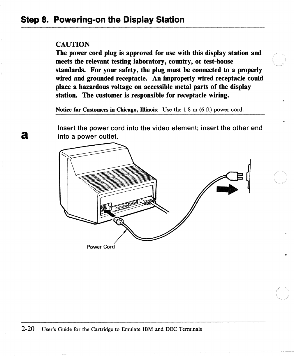
Step 8. Powering-on the Display Station
CAUTION
The power cord plug is approved for use
meets the relevant testing laboratory, country, or test-house
standards. For your safety, the plug must
wired and grounded receptacle. An improperly wired receptacle could
place a hazardous voltage on accessible metal parts
station. The customer is responsible for receptacle wiring.
with
this display station and
be
connected to a properly
of
the display
Notice for Customers in Chicago,
Insert the power cord into the video element; insert the other end
a into a power outlet.
Power Cord
D1inois:
Use the
1.8 m (6
ft) power cord.
2-20 User's Guide for the Cartridge to Emulate IBM and DEC Terminals
t\
\ ,
"'---
j
Page 46
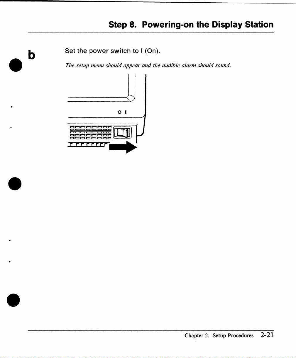
Step
8.
Powering-on the Display Station
•
Set the
The setup menu should appear and the audible alarm should sound.
...............
power
,.
,..,..
switch
o I
to I (On).
•
Chapter
2.
Setup Procedures
2-21
Page 47

Step
9.
Adjusting the Screen Brightness
Adjust the (
comfortable
*rrrr-r-rr-
-0-
) brightness knob until the
viewing
level.
brightness
is set to a
2-22
User's Guide for the Cartridge to Emulate IBM and DEC Terminals
Page 48

Step 10. Positioning the Video Element
Customers who do not have the stand (optional):
If
a stand is
not
available for the 3151, do this step .
•
•
Customers who have the stand (optional):
Skip this step; go to page 2-24 .
Lift the
rear
of the video element to
slide
the
tilt
foot as needed .
•
Chapter
2.
Setup Procedures 2-23
Page 49

Step 11. Adjusting the Audible Alarm Sound
To increase the sound of the audible alarm:
a
Press and hold
To decrease the sound of the audible alarm:
b
2-24
Press and hold
Then press
n
/~
o
Repeat these steps until the alarm is set to a comfortable sound
level.
User's Guide for the Cartridge
OJCIJ
001£)
to
OCD
Emulate IBM and DEC Terminals
Page 50

Step 12. Defining Setup Values
You must define the setup values so that the display station can correctly
or
communicate with the host system
up
the display station should have selected the values for your installation.
printer. The person responsible for setting
•
•
"Setup Parameters List (emulation)" on page
mode to emulate the DEC VT220.
ATTACH)"
"Setup Parameters List (IBM 3151/3101)" on page 3-32 lists all possible values
for IBM
to emulate the DEC VT220 is provided in
(emulation)" on page
mode is provided in
page 3-25. The explanation
provided in
If you use only a
If you use only an IBM system, go to page 2-29 and do step 12B .
If you use both
steps 12A and 12B.
Note: The location
other modes differs.
DEC
VT220 and page 2-30 for other modes .
on page 3-30 lists all possible values for SYSTEM ATTACH mode.
3151
and IBM
IBM
3101
3-2.
The explanation
"Setup Menus and Setup Values (SYSTEM ATTACH)" on
3151
ASCII
DEC
system, go to page 2-26 and
DEC
and IBM systems, go to page 2-26 and do
of
the Setup key in the mode to emulate the DEC VT220 and
For
the location,
"Setup Parameters List (SYSTEM
modes. The explanation
of
the values for IBM
Display Station Guide to Operations,
see
3-23
lists all possible values for the
of
the values for the mode
"Setup Menus and Setup Values
of
the values for SYSTEM ATTACH
3151
and
3101
modeS'
is
do
step 12A.
page 2-27 for the mode to emulate the
•
Chapter
2.
Setup Procedures 2-25
Page 51

Step 12A. Defining Setup Values (emulation)
a
Billl:';"
On-Line/Local
Transparent
Machine
Operation
VT100
User
Features
This step describes how
DEC
VT220.
A.s
described in Step
below.
Note:
not
Mode VT200 CONTROL 7
ID
If
you have already defined the setup values, the GENERAL menu will
appear. Press the Setup key.
DISPLAY
Mode
Mode
COMMUNICATION
to
8,
the setup menu (GENERAL) should appear
SET
1
.•
:.11:
UNLOCK
defme the setup values for the mode
U P
••
OFF
ECHO
VT220
MEN
KEYBOARD
Auto
Answerback
Answerback
Characters
U
PRINTER FUNCTION
Answerback
Concealed
to
emulate the
as
shown
OFF
OFF
MULTINATIONAL
/\
"'-
'
./
2-26
User's Guide for the Cartridge to Emulate IBM and DEC Terminals
Page 52

Step 12A. Defining Setup Values (emulation)
•
•
b
Refer to Figure 3-15 on page 3-23;
the value, if needed .
1 Using the Cursor Move keys
box) whose value you want to change.
2 Press the Space Bar to display each value.
appears.
3 Repeat steps 1 and 2 until you have changed all necessary values.
Note:
characters) instead
4 Select the next menu
values. Follow the same procedures for all menus
COMMUNICATION, KEYBOARD, and PRINTER), except the FUNCTION
menu, which has different purposes.
For
the answerback message, key in the characters (up to
of
pressing the Space Bar.
by
(t
pressing the Enter key, and change all necessary
~
.-
select
-.),
the field and change
select any field (high-intensity
Do
this until the desired value
(GENERAL, DISPLAY,
DOD
30
•
Setup
If
If
you do
Values"
Space
You Need Help
not
on page
Bar
understand the above procedures,
3-33
for a more detailed explanation.
~
BmB
i i
Cursor
Move
see
Chapter
~~~§
CIJI
Enter
"How to Define Setup
2.
Setup Procedures 2-27
Page 53

Step 12A. Defining Setup Values (emulation)
Select the FUNCTION menu to save the definitions that you have
c
made on the GENERAL,
DISPLAY, COMMUNICATION,
KEYBOARD, and PRINTER menus.
GENERAL
Clear
Recall
1 Select the
menu.
The
DISPLAY
Display
FUNCTION
FUNCTION
COMMUNICATION
menu should look like this.
SET
Clear
Save
menu by pressing the Enter key from the
U P
Comm
MEN
KEYBOARD
U
PRINTER 1i1'llill,II'
Reset
Default
2 Select the Save field using the Cursor Move keys
3 Press the Space Bar to save the definitions
appear).
(a
blinking Completed should
Terminal
(1
! +- -+).
PRINTER
2-28
4
If
you use only a
Setup Procedures
DEC
system, press the Setup key to exit this mode.
are
now complete.
If you use an IBM system also, go to page 2-29 and do step 12B.
User's Guide for the Cartridge
to
Emulate IBM and
DEC
Terminals
(>
'<...
• .>J
Page 54

Step 12B.
~efining
Setup Values (IBM Mode)
•
a
•
This step describes how
ATTACH is taken as
If
the
3151
displays the FUNCTION menu for the mode to emulate the
VT220, select the GENERAL menu by pressing the Enter key; select SYSTEM
ATTACH for the Machine Mode by repeatedly pressing the Space Bar.
If
the
3151
displays the GENERAL menu for the mode to emulate the
VT220, select SYSTEM ATTACH for the Machine Mode by repeatedly pressing
Space Bar.
the
At
this point, the GENERAL menu will appear as shown below.
If
Note:
not appear. Press the
you have already defined the setup values, the GENERAL menu will
COMMUNICATION
to
define the setup values for IBM mode. SYSTEM
an
example .
Setup key .
SET
U P
MEN
KEYBOARD/PRINTER
U
DEC
DEC
FUNCTION
•
Machine
Screen
Rowand
Scroll
Auto
LF
Forcing
Mode
Column
Insert
SYSTEM
ATTACH
NORMAL
24 x
SMOOTH
OFF
OFF
80
F
CRT
Saver
Line
Wrap
Tab
Term.ID
Print
Chapter
2.
Setup Procedures
OFF
OFF
FIELD
LOCAL
2-29
Page 55

Step 12B. Defining Setup Values (IBM Mode)
b
Refer
the
1 Using the Cursor Move keys (f
2 Press the Space Bar to display each value.
to
Figure 3-20 on page 3-30;
value,
box) whose value you want to change.
appears.
if
needed.
~
~
select
-+), select any field (high-intensity
the field and change
Do
this until the desired value
3 Repeat steps 1 and 2 until you have changed all necessary values.
Note:
characters) instead
4 Select the next menu
values. Follow the same procedures for all menus
COMMUNICATION, KEYBOARD/PRINTER), except the FUNCTION
menu, which has different purposes.
o
0000 0000
For
the Term. ID message, key in the characters (up to 20
of
pressing the Space Bar.
by
pressing the Send key, and change all necessary
(GENERAL,
0000
000
t
Ctrl Space
H You Need Help
If
you do not understand the above procedures,
Values"
2-30 User's Guide for the Cartridge
on
t
page 3-33 for a more detailed explanation.
Bar
to
Emulate
I
Send Cursor Move Setup
see
"How to Define Setup
IBM
and DEC Terminals
Page 56

Step 12B. Defining Setup Values (IBM Mode)
c
•
•
GENERAL
Recall
Reset
Select the FUNCTION menu to save
made
menus.
1 Select the FUNCTION menu
on
the
GENERAL, COMMUNICATION, KEYBOARD/PRINTER
by
pressing the Send key from the
KEYBOARD/PRINTER menu.
The FUNCTION menu should look like this.
SET
COMMUNICATION
Terminal
U P
MEN
KEYBOARD/PRINTER
the
definitions
U
Default
that
you
have
•
2 Select the Save field using the Cursor Move keys
3 Press the Space Bar.
A blinking Completed should appear telling you that the setup-value
definitions are saved.
4 Press the Setup key to exit this mode .
Setup Procedures
are
now complete.
Chapter
(1
! +- -+).
2.
Setup Procedures 2-31
Page 57

Defining
Function
Keys
(emulation)
Defining
Function
You can define function keys F6 through F20 from the keyboard
command, however, the definitions
ESC sequences, CSI sequences in 7-bit extended form,
assigned to each function key.
Figure
•
2-3
0000
Keys
shows location
(emulation)
~~~~
will
be lost when power is turned off.
of
the keys used for this step.
~B~~
~~~
{HI'P){Do)
or
character strings can
888
o
Ctrl
Figure
ESC
1~3.
BOD
(Oef
F)
Keys Used for Defming Function Keys (emulation)
II
Enter
or
by the host
i
be
;"
~j
/-\
( .
\ :
'" /
A
2~32
User's Guide for the Cartridge to Emulate IBM and DEC Terminals
Press and hold the
The/unction key menu should appear as shown below.
a
a: A two-digit number
b:
The function is entered here (up to
Cirl
key; then press the
b
(06
through 20)
of
a function key is entered here.
70
characters).
Def
F key.
Page 58
Defining
Function
Keys
(emulation)
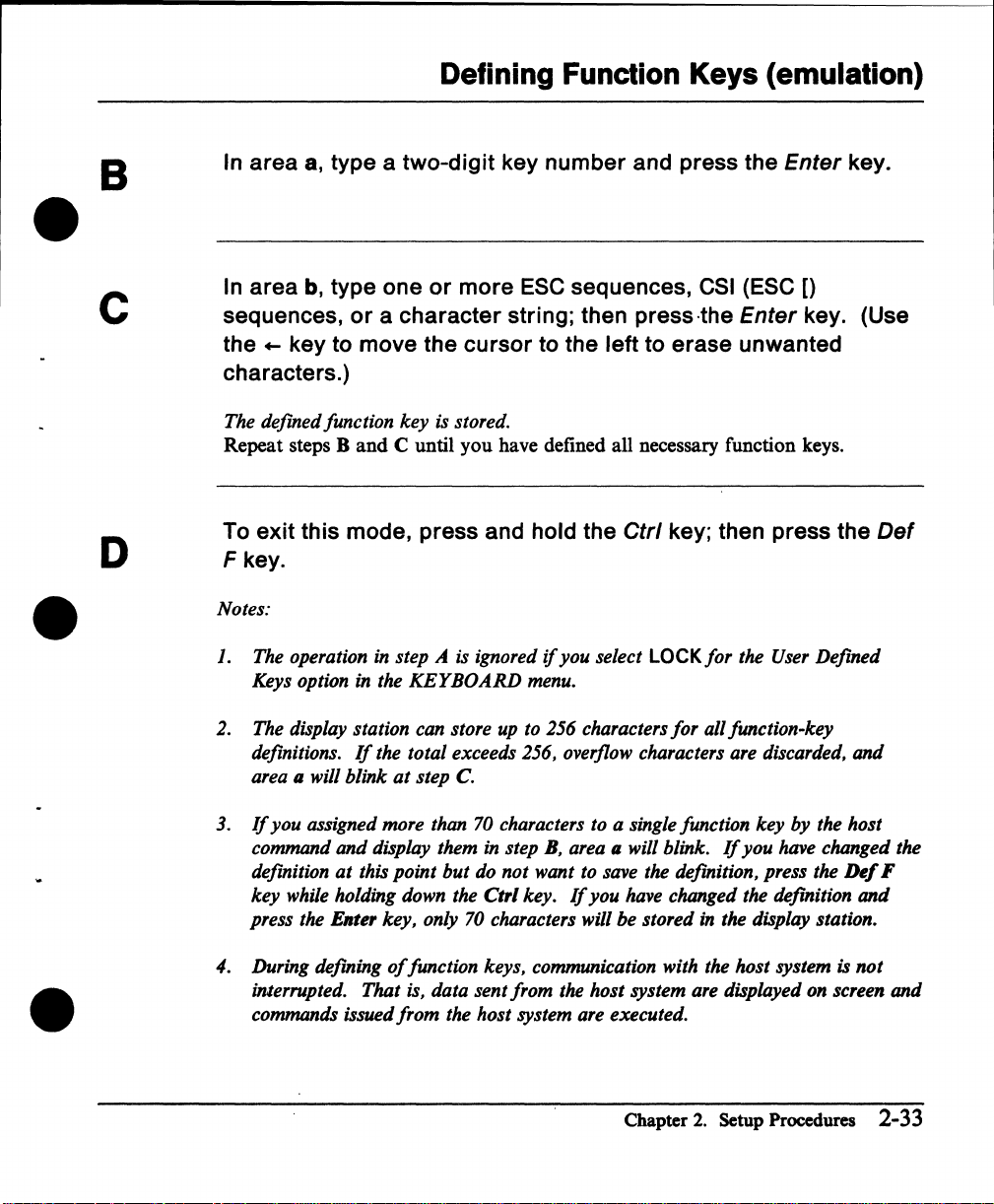
B
•
c
D
•
In area
In area
sequences,
the
characters.)
The
Repeat steps B
To exit this mode, press and hold the
Fkey
Notes:
J. The operation in step A is ignored
2. The display station can store up to 256 characters
8,
type a two-digit key number and press the Enter key.
b,
type one
or
...
key to move the cursor to the left to erase unwanted
defmed
Keys option in the
definitions.
area
.
II
function
will
blink
and
If
or
more
a character string; then press·the Enter key. (Use
key
is stored.
C until you have defined all necessary function keys.
KEYBOARD
the
total
exceeds 256, overflow characters are discarded,
at
step
C.
ESC
sequences,
if
you
menu.
Ctrl
select LOCK
CSI
(ESC
key; then press the
for
the User
for
all function-key
[)
Defmed
and
Def
•
3.
If
you
assigned more than 70 characters to a single function
command
defmition
key
while holding down the
press the Enter
4.
During defming
interrupted.
commands issued
and
display them in step
at
this
point
but
key,
only 70 characters will
of
function keys, communication with the
That
is, data sent
from
the
B,
area
do
not
want to save the defmition, press the
Ctrl
key.
If
you
from
the
host
host
system are executed.
key
by
the host
II
will blink.
have changed the defmition
be
stored
system are displayed on screen
Chapter
If
you
have changed the
in the display station.
host
system is
2.
Setup Procedures 2-33
Ikf
and
not
F
and
Page 59

Setting Tab Stops (emulation)
Setting
A
Tab Stops (emulation)
You can set tab stops for later use from the keyboard
Figure 2-4 shows the locations
o
0000
of
the keys used for this step.
0000
000
or
by a host command. G
BBB
[)
BmB
i
Ctrl Tab-+
Figure 2-4.
Do
the following to set the tab stops using the Tabs key.
Press and hold the
The scale line should appear on the current line. In 80-column mode, the scale line
is graduated up to the
mode, it is graduated up to the 132nd column.
stops are displayed
the Cursor Move keys
screen.
Keys
Tabs
Used for Setting Tab Stops (emulation)
etrl
key; then press the Tabs key.
80th column as shown
in
reverse video. You can move the scale line to any line using
(t
!). The instructions also appear
Cursor Move
in
the figure below, and
On
the scale line, the current tab
at
the bottom
in
132-column
of
/~
i
the
+
----1----+ ----2----+ ----3----+ ----4----+ ----5----+ ----6----+ ----7----
< ---
2-34 User's Guide for the Cartridge to Emulate IBM and DEC Terminals
+
----
>
Page 60

•
Setting
Setting tab stops
Using the Cursor Move keys (4- -+), move the cursor to the desired
1
the
-+
key.
scale line.
tab-stop location on
2 Then press the Tab
Tab
Stops
(emulation)
•
B
The tab stop is set
Resetting tab stops
1 Using the Cursor Move keys (4- -+), move the cursor to the desired
tab-stop location
2 Then press the Tab
The tab stop is cleared
Clearing all tab stops
Press either Numeric 0 key.
SeHing default tab stops
Press either Numeric 8 key.
Tab stops are set every eight columns.
To exit this mode, press and hold the
Tabs key.
and
displayed in reverse video.
on
the scale line (displayed
-+
key.
and
the video returns to normal .
in
reverse video).
etrl
key; then press the
•
If
you want to save the tab settings that you have made here, perform the
operation
in
the
FUNCTION
menu .
Chapter
2.
Setup Procedures 2-35
Save
Page 61

Defining Function Keys (IBM Mode)
Defining Function Keys
You can define function keys
command. The operation
native mode.
After making the definition
FI
when
F36 are selected when
ESC sequences,
Figure 2-5 shows location
Ctrl
through F12 are pressed respectively, with the
FI
or
character strings can
ESC
(Oef
F)
(IBM Mode)
F1
through F36 from the keyboard
of
defining function keys is exactly
of
each function key, F13 through F24 are selected
through F12 are pressed with the
be
assigned to each function key.
of
the keys used for this step.
Send
Clear
the"
Shift
key; F25 through
Shift
or
by the host
same as that in
key and Gtrl key.
Figure 2-5. Keys Used for Defining
2-36 User's Guide for the Cartridge
to
Emulate
FUDction
IBM
Keys (IBM Mode)
and DEC Terminals
Page 62

Defining Function Keys (IBM Mode)
A
e
B
ec
Press and hold the
The function key menu should appear as shown below.
a
a: A two-digit number
b:
The function is entered here (up to
In
area
a,
type a two-digit
In
area
b, type
string; then press the Send key.
The defined function key is stored.
Repeat steps
Band
etrl
key; then press the
b
(01
through 36)
key
number
one
or
more
C until you have defined all necessary function keys.
ESe sequences,
of
a function key
64
characters).
and press the Send key.
Def
F key.
is
entered here.
or a character
e
D
To
exit
this
mode, press and hold the
F key.
Notes:
1.
The display station can store
definitions.
area a will blink
2.
If
you assigned more than 64 characters to a single function key by the host
command and display them
If
the total exceeds 512, overflow characters are discarded, and
at
step
up
to 512 characters
C.
in
step B, area a will blink.
etrl
key; then press the
for
all function-key
If
you have changed the
Chapter
2.
Setup Procedures 2-37
Def
Page 63

Defining Function Keys (IBM Mode)
definition
key
press the
at
this point but
while holding down the Ctrl key.
Send
key, only 64 characters will be stored
do
not want to save the definition, press the
If
you have changed the definition and
in
the display station. 0
Del
F
~
2-38 User's Guide for the Cartridge to Emulate IBM and DEC Terminals
Page 64

Setup Menus and Setup Values
Ch~pter
•
•
3.
Setup Menus and Setup Value Descriptions
This chapter describes setup menus; what the setup menus are; what the setup
values mean; and how you can change the setup values.
use
Before you can
communication interface, line speed, and parity) must
information, called setup values,
host system
may also want to define the type
reverse video) to
Most setup values can also be defined by host commands.
Warning:
means that when you first install the display station
replace the video element, you must define these values. Otherwise,
the display station may
or
the display station, certain information (such as the type
be
set correctly. Such
is
necessary before you can communicate with a
an optional device (such as a printer) on the auxiliary port. You
of
scrolling or screen appearance (normal
be
used. You can define setup values
The setup values are stored in the video element, which
not
work correctly .
by
using the setup menus.
or
if
you ever
of
or
•
Chapter
3.
Setup Menus and Setup Value Descriptions
3-1
Page 65

Setup Menus and Setup Values (emulation)
Setup Menus and Setup Values (emulation)
In the mode to emulate the DEC VT220, the
use
menus that you
GENERAL
•
DISPLAY
•
COMM UNICA
•
KEYBOARD
•
PRINTER
•
Fl)NCTION.
•
Each menu, except the
fields. The
definitions
When you power-on the display station the first time with the emulation cartridge
inserted, the
pressing the
Some setup parameters are different in emulation mode. These differences are \ j
described in "Equivalent Setup
the meanings
Note: During setup mode,
• the instructions for the menu are displayed
FUNCTION
or
GENERAL
Setup key.
to define setup values.
TION
FUNCTION
menu
to reset the setup-value definitions to the factory-set default values.
menu appears. You can also display the menu by
of
the setup parameters in the menus.
menu, contains the setup-value-definition
is
used, for example, to save the setup-value
Parameter~"
3151
provides the following setup
on
page 3-20. This section describes
at
the bottom
of
the screen.
• on-line operations are suspended (the incoming data is stored in the display
station).
3-2
User's Guide for the Cartridge to Emulate IBM and DEC Terminals
I '
/ "
"'_/
Page 66

GENERAL Menu (emulation)
GENERAL Menu (emulation)
Figure
setup parameters, their possible values, and their meanings.
3-1
shows the GENERAL menu. Figure 3-2 on page 3-4 explains
the
•
SET
.liin;,,, DISPLAY
On-Line/Local
Transparent
Machine
Operation
VT100
User
.~--------------~
Figure 3-1. GENERAL Menu (emulation)
ID
Features
Mode
Mode
Mode
COMMUNICATION
.,I:
VT200 CONTROL 7
U P
••
Ui
OFF
ECHO
VT220
UNLOCK
MEN
KEYBOARD
Auto
Answerback
Answerback
Answerback
Characters
U
Concealed
PRINTER
FUNCTION
OFF
OFF
MULTINATIONAL
•
Chapter
3.
Setup Menus and Setup Value Descriptions 3-3
Page 67

GENERAL Menu (emulation)
Setup Possible
Parameters
On-Line/Local
Transparent
Values
ON-LINE
LOCAL
OFF I ON
Mode the DEC VT220. When
Machine
Mode
Operation
VT200 CONTROL 7
VT100
VT52
VT200 CONTROL 8
ECHO
Mode system;
CHAR
VT100
ID
VT220
VT100
VT101
VT102
Meanings
The display station operates in on-line mode and can
communicate with a host system.
The display station operates in local mode.
from the keyboard is displayed only on the screen.
cannot
not displayed until
be
sent, and data received from the host system is
ON-LINE is selected.
Transparent mode is equivalent to display control mode in
handled as character strings. This means that the control
characters (except the LF, VT, and
displayed on the screen without performing their functions.
be
This mode may
used for debugging programs.
The display station operates in the selected machine mode.
Data
entered from the keyboard is sent only to the host
it
is not displayed. Echo mode is equivalent to
local echo mode in the DEC VT220.
Data
entered from the keyboard is sent to the host system
and displayed on the screen. Character mode is equivalent
to local echo mode in the DEC VT220.
This parameter is only effective when you select VT100 for
the machine mode. The display station returns the selected
response for the Device Attribute command.
Data
entered
Data
ON is selected, commands are
FF
characters) are
~~~
~-~)
no
Figure 3-1
(part 1 of
3-4 User's Guide for
1). Setup Parameters io the GENERAL Menu (emulation)
the
Cartridge to Emulate
IBM
and DEC Terminals
Page 68

Setup Possible
Parameters Values Meanings
User
Features
•
Auto
Answerback automatically sent to the host system when the
Answerback
Answerback
Concealed displayed
Characters
UNLOCK
LOCK
OFF I
ON
OFF I ON
MULTINATIONAL
GENERAL Menu (emulation)
When
LOCK is selected,
define the following setup parameters:
Auto
•
•
•
•
•
When
communication is started.
You
message.
When
The
Repeat
Scroll
Screen
Tab
Stops
Keyboard Lock.
ON is selected, the answerback message is
can
enter
up
ON is selected, the answerback-message entry is
on
the screen.
DEC
supplemental character set can be used.
an
application program
to
30 characters for the answerback
cannot
not
• Figure 3-2 (Part 2 of
•
2).
Setup Parameters in the GENERAL Menu (emulation)
Chapter
3.
Setup Menus
and
Setup Value Descriptions 3-5
Page 69

DISPLAY
Menu (emulation)
DISPLAY
GENERAL
Screen
Cursor
Rowand
Auto
Scroll
CRT
Saver
Figure 3-3.
Menu
(emulation)
Figure 3·3 shows
parameters,
"ilii';I)
Column
Wrap
DISPLAY
the
DISPLAY menu. Figure 3-4
their
possible values,
SET
COMMUNICATION
NORMAL
SMOOTH
Menu (emulation)
U P
ON
24xlO
OFF
ON
on
page
3·7
explains
and
their meanings. .
MEN
KEYBOARD
F
U
PRINTER
the
setup
FUNCTION
(~\
~.
/
'\
I I
\,
/
3-6
User's Guide for the Cartridge to Emulate IBM and DEC Terminals
Page 70

DISPLAY Menu (emulation)
Setup
Parameters Values Meanings
Screen
•
Cursor
Rowand
Column
Auto
Scroll
•
CRT
Wrap
Saver
Possible
NORMAL
REVERSE
ON
I OFF
24x
80
24 x 132
25x80
25
x 132
OFF
ON
SMOOTH F
SMOOTHS
JUMP
ON
I OFF
The whole screen is displayed in normal video.
The whole screen is displayed in reverse video.
When OFF
The display station uses a screen size based
rows (lines) and columns (characters). The contents
screen are cleared when the value is changed.
A character received beyond the right margin is written
over the last character
A character received beyond the right margin is displayed
at
the first position
For
entered
For
entered
SMOOTH F).
For
entered
When
received from the host system
keyboard for
entered
data
is
selected, the cursor is
of
the current line.
of
the next line.
example, when the last character
or
received, all lines move up slowly.
example, when the last character
or
received, all lines move up slowly (slower
example, when the last character
or
received, all lines move up rapidly.
ON
is
selected, the screen goes blank
15
minutes. When
and
this function
again.
is
active, the screen displays the
not
or
entered from the
data
displayed.
on
the selected
of
the last line is
of
the last line is
of
the last line is
if
no
is
received
data
or
of
the
than
is
Figure 3-4. Setup Parameters in the DISPLAY Menu (emulation)
•
Note:
CRT
Chapter
means cathode ray tube.
3.
Setup Menus and Setup Value Descriptions
3-7
Page 71

COMMUNICATION Menu (emulation)
COMMUNICATION Menu (emulation)
Figure
3-5
shows the COMMUNICATION menu. Figure 3-6 on page
explains the setup parameters, their possible values, and their meanings. "'--
Note: The Line Control parameter is not effective when RS-422A is selected for
the interface.
SET
GENERAL
DISPLAY
COMMUNICATION
Transmit
Receive
Data
Length
TRANSMIT
Parity
Parity
Stop
Check
Bit
Figure 3-5. COMMUNICATION Menu (emulation)
U P
4800
8
NO
ON
1
XOFF
Interface
Line
Break
Disconnect
Limited
MEN
U
KEYBOARD
Control
Transmit
PRINTER FUNCTION
NORMAL
Delay
3-9
64
RS-232C
IPRTS
25
ON
(\)'
('-\
~)
3-8 User's Guide for the Cartridge to Emulate IBM and DEC Terminals
Page 72

Setup Possible
Parameters Values Meanings
Transmit
•
Data
Parity
•
Parity Check
XOFF
•
Interface
Receive
Length
Stop Bit
COMMUNICATION Menu (emulation)
See
page The display station sends data to the host system
3-23 selected line speed (bps).
TRANSMIT
817
NO
EVEN
ODD
MARK
SPACE
ON I OFF
112
64
128
300
NO
RS-232C
RS-422A
The transmit line speed (bps) is used for the display station
to receive data from the host system.
The display station uses the selected data length (7-bit
8-bit).
The display station uses the selected parity. Parity is
added when
When
The display station places one
character.
The display station sends
system when the buffer
the selected number
is
sent (when
The display station communicates with the host system
using the EIA RS-232C
NO
ON
is
selected, parity
NO
is selected.
of
of
characters,
is
selected).
or
is
checked.
or
two bits after each data
an
XOFF
the display station is filled with
RS-422A interface.
character to the host
or
no
XOFF
at
the
or
not
character
Figure 3-6 (Part 1 of 2). Setup Parameters
•
in
Chapter
the COMMUNICATION Menu (emulation)
3.
Setup Menus and Setup Value Descriptions 3-9
Page 73

COMMUNICATION Menu (emulation)
Setup
Possible
Parameters Values Meanings
Line Control
IPRTS
The display station controls the RS-232C signal line using
IPRTS (induced permanent request to send). IPRTS
handles the CTS (clear to send), RLSD (received line
DSR (data set ready) signals as
always on. This parameter
PRTS
signal detect), and
signals
RS-232C
to
were
is
selected for the interface. IPRTS is equivalent
"EIA Port, Data Leads Only" in the DEC VT220.
The display station controls the RS-232C signal line using
PRTS (permanent request to send). PRTS handles the
CTS, RLSD, and DSR as modem signals. This parameter
is effective when RS-232C
PRTS
is
equivalent to "EIA Port, Modem Control" in the
VT220.
DEC
Break
Disconnect
Delay
Limited
NORMAL
SHORT
NO
2 s I 60 ms
ON I OFF
The display station sends a
system when the
Break key
The display station sends a
system when the
Break key is pressed.
The display station does not send a break signal to the
host system when the
Break
Communication with the host system is disabled for the
selected period after the
When ON is selected, the number
Transmit host system is limited to
of
the line speed.
is
effective when
is
selected for the interface.
500
ms break signal to the host
is
pressed.
170
ms break signal to the host
key
is pressed.
RLSD signal is lost.
of
characters sent to the
150
to
180
per second, regardless
if
(-~
~)
the
•
Figure 3-6 (Part 2
of
2). Setup Parameters
in
the COMMUNICATION Menu (emulation)
3-10 User's Guide for the Cartridge to Emulate IBM and DEC Terminals
Page 74

KEYBOARD Menu (emulation)
KEYBOARD Menu (emulation)
•
•
GENERAL
New
Keys
Lock
Auto
Margin
Warning
Figure
Figure
setup parameters. their possible values, and their meanings.
Line
Repeat
Bell
3-7.
KEYBOARD
DISPLAY
Bell
3-7
shows the
KEYBOARD
SET
COMMUNICATION
TYPEWRITER
CAPS
Menu
(emulation)
U P
CR
ON
ON
ON
Numeric
Cursor
User
menu. Figure
MEN
Keypad
Keys
Defined
U
3-8
on page 3-12 explains the
FUNCTION
NORMAL
NORMAL
Keys
UNLOCK
"
•
Chapter
3.
Setup Menus and Setup Value Descriptions
3-11
Page 75

KEYBOARD Menu (emulation)
Setup
Parameters
New Line
Possible
Values
CR
Meanings
A
CR
(carriage return) character is generated when the
Return key is pressed.
Keys
Lock
Auto Repeat
CR/LF
TYPEWRITER
DATA
PROCESSING
CAPS
SHIFT
ON I OFF
Both the
when the
TYPEWRITER is assumed regardless
CR
and
LF
(line feed) characters are generated
Return key is pressed.
of
the setting.
The alphabetic keys generate uppercase characters only.
The alphabetic keys generate uppercase characters only
and
numeric/symbol keys generate the upper half label
of
character
When
each key.
ON
is
selected, most keys continue
to
generate the
character while being pressed.
Margin Bell
ON I OFF
When ON is selected,
an
audible
alarm
will sound when the
cursor reaches the right margin; either column
Warning
Bell
ON I OFF
(80-column mode)
When ON is selected,
operation error occurs
or
column
an
or
125
(132-column mode).
audible alarm will sound when
the display station receives the
control-G code.
Numeric
NORMAL
The display station generates the corresponding ASCII
Keypad character when a numeric keypad key is pressed.
APPLICATION
The display station generates the application control
function when a numeric keypad key is pressed.
Cursor Keys
NORMAL
The display station generates the corresponding ASCII
character when a cursor key is pressed.
APPLICATION
The display station generates the application control
function when a cursor key is pressed.
User Defined
Keys
UNLOCK
LOCK
When LOCK is selected, neither
the
De!
F key can define the function keys.
an
application program
73
an
•
nor
Figure 3-8. Setup Parameters
in
the KEYBOARD Menu (emulation)
3-12 User's Guide for the Cartridge to Emulate
IBM
and DEC Terminals
(
Page 76

PRINTER Menu (emulation)
PRINTER Menu (emulation)
•
•
Figure 3-9. PRINTER Menu (emulation)
GENERAL
Speed
Data
Parity
Print
Data
Stop
Length
Bit
Region
Figure 3-9 shows the PRINTER menu. Figure 3-10
setup parameters, their possible values, and their meanings.
DISPLAY
SET
COMMUNICATION
FULL SCREEN
NATIONAL
U P
4800
8
NO
1
ONLY
MEN
KEYBOARD
Print
Print
Mode
Terminator
U
on
page 3-14 explains the
lijili:iii;i
FUNCTION
NORMAL
NO
•
Chapter 3. Setup Menus
and
Setup Value Descriptions 3-13
Page 77

PRINTER
Menu
(emulation)
Setu.,
Parameters
Possible
Values Meanings
Speed See page The display station sends
Data
Length
3-24 the auxiliary
817
The display station uses the selected
port
at
the selected line speed (bps).
8-bit).
Parity
Stop Bit
NO
EVEN
ODD
MARK
SPACE
1 I 2
The display station uses the selected parity. Parity is
added when NO is selected.
The display station places one
character.
Print Region
FULL
SCREEN
The display station sends the complete screen
printer (optional device) when a print operation is
requested.
SCROLL
REGION
The display station sends a
margin through bottom margin)
device) when a print operation is requested.
Data
NATIONAL
ONLY
The display station uses the national code page (NCP) to
map the code to the character
is sent
to
the printer (optional device).
regarded as A.
NATIONAL
& LINE
DRAWING
The display station uses
character
and
the resulting character is sent to the printer
(optional device). The
DEC
also sent to the printer (optional device).
ALL
The display station sends all characters, including the
control characters
A),
to the printer (optional device).
and
diacritical characters (for example,
..
data
to the optional device
data
length (7-bit
or
two bits after each
part
of
the screen
to
the printer (optional
and
the resulting character
For
example, A is
NCP
to
map
the code to the
line-drawing characters are
data
data
on
or
not
data
to the
(top
(
"'-.
\,
)
Figure 3-10
(part 1 of
2). Setup Parameters
in
the PRINTER Menu (emulation)
3-14 User's Guide for the Cartridge to Emulate IBM and
DEC
Terminals
Page 78

PRINTER Menu (emulation)
•
Figure 3-10
•
Setup
Parameters
Print Mode
Print
Terminator
Possible
Values Meaaings
NORMAL
AUTO
CONTROLLER
NO I FF
(Part 1 of
1). Setup Parameters in the PRINTER Menu (emulation)
A print operation is performed when requested from the
keyboard.
The current line is sent to the printer (optional device)
when a line feed, a form feed,
received from the host system;
occurs.
Data
from the host system is sent
device), but
When
printer (optional device) after the screen data is printed.
Note: This option is effective only for the print screen
operation.
not
displayed
FF
is selected, the form feed character is sent
or
or
on
the screen.
a vertical
an
to
tab
character is
auto wrap condition
the printer (optional
to
the
•
Chapter 3. Setup Menus
and
Setup Value Descriptions 3-15
Page 79

IBM 420"Leroprinter or IBM 4202 Proprinter XL Connection
The
IBM
4201
Proprinter
be
attached
example
Proprinter
Figure 3·11; other switches
to
the
3151
of
the printer switch settings (on the serial interface module) when the
is attached
(or
IBM 4202 Proprinter XL) with a serial interface can
via
an
I/O
cable
(part
to
the 3151. Switches A7, B3,
may
be set differently.
6343373). Figure 3·11 shows
B4
must
an
be set as in
Parameter
Line Speed (19200)
Parity (EVEN) A4
Pacing (enable) A6
.
Word
Length
Stop Bit (1)
Mode
(Normal)
(8
bit)
.
Figure 3-11. Example
For
the above example, the setup parameters for the printer must be set
PRINTER
• Speed: 19200
•
nata
• Parity:
• Stop Bit: 1
•
Print
menu as follows:
Length: 8
EVEN
Region:
FULL
Switch Setting
Al
A2
A3
AS
A7
BI
B2
B3
B4
of
the PropriDter (XL) Switch Settings
SCREEN
or
SCROLL
REGION
On
On
On
On
On
Off
Off
Off
Off
Off
Off
in
the
3-16 User's Guide for the Cartridge to Emulate IBM and
DEC
Terminals
Page 80

•
•
• Data: NATIONAL ONLY (always)
• Print Mode: NORMAL, AUTO, or CONTROLLER·
• Print Terminator:
NO
(always)
•
If
CONTROLLER is selected for the Print Mode, the printer
host system; not by the 3151.
Chapter
3.
Setup Menus and Setup Value Descriptions 3-17
is
controlled
by
the
Page 81

FUNCTION Menu (emulation)
FUNCTION Menu (emulation)
GENERAL
Figure 3-12 shows the FUNCTION menu. Figure
3151
The
(volatile memory) and NVM (non-volatile memory). The contents
when power is turned off; the contents
When you power-on the
factory-set, setup-value definitions are copied to
values and are used unless you redefine them.
When you power-on the
the contents
VM. The contents
in
setup value by pressing the
save function
be
to
has two storage areas for saving the setup-value definitions: VM
of
NVM are retained.
3151
for the first time, NVM contains no values and
3151
after saving your setup-value definitions (in NVM),
of
NVM are copied to VM. The
of
VM are immediately changed when you select the other
Space Bar in the setup menus.
at
used later.
DISPLAY
this time, the contents
SET
COMMUNICATION
U P
of
VM are copied to NVM enabling them
MEN
KEYBOARD
3-13
explains each function.
VM. These are called default
3151
operates using the setup values
If
you perform the
U
PRINTER
of
VM are lost
..
iI:Ii",I:.
~)
C
Figure
Clear
Recall
3-12.
Display
FUNCTION Menu (emulation)
Clear
Save
Carom
Reset
Default
3-18 User's Guide for the Cartridge to Emulate IBM and DEC Terminals
Terminal
Page 82

•
FUNCTION Menu (emulation)
If
you select
this field and
press the space bar this
Clear Display
Recall
Clear
Comm
Save
Reset Terminal The display station's operating parameters (such as the scroll region
Default The setup-value definitions
will
occur
Screen is erased.
The contents
Power-on reset (except checking the internal circuits) is performed.
Communications are initialized.
The
setup-value definitions
in VM) are also saved in NVM.
and
the character set) are reset to their default values. Some
setup-value definitions in
communications are not initialized.
copied to VM.
of
NVM
are copied
and
NVM
and
to
VM
and
the screen is erased.
tab
settings (defined now
are also changed,
tab
settings set
in
and
saved
but
the factory are
•
•
Figure 3-13. Functions
in
the FUNCTION Menu (emulation)
Chapter
3.
Setup Menus and Setup Value Descriptions 3-19
Page 83

Equivalent Setup Parameters
Equivalent Setup Parameters
The center column in Figure 3-14 on this page shows the DEC VT220 setup
parameters and the right column shows their equivalent ones in emulation mode.
Note: DEC VT220 does not define
is
always on and RS-232C
DEC
VT220 Menus DEC VT220 Parameters IBM 3151 Parameters
SetUp Directory
Display Setup
General Setup
On-Line/Local
Setup
Keyboard
Columns
Controls
Auto Wrap Auto Wrap
Scroll Scroll
Text/Screen Screen
Text Cursor Cursor
Cursor
Mode Machine Mode
VT100
User Defined Keys
User Features
Keypad
used for the interface.
Style
CRT
Saver and Interface. CRT Saver is
On-Line/Local
GENERAL
Not available
Not
available
Rowand
Transparent Mode
GENERAL menu
Alt
VT100
User Defined Keys
KEYBOARD menu
User Features
Numeric Keypad
KEYBOARD menu
Csr
Column
key
10
(j
in the
menu
in the
in the
in the
Figure 3-14
(Part 1 of
3). Equivalent Setup Parameters (emulation)
3-20 User's Guide for the Cartridge to Emulate IBM and DEC Terminals
~.
I
"'--
..
j
Page 84

Equivalent Setup Parameters
•
•
DEC VT220 Menus DEC VT220 Parameters
General Setup
Communications
Printer Setup
Setup
Cursor Keys
New Line
Multinational/National
Transmit
Receive Receive
XOFF
Bits/Parity
Stop
Bit
Local Echo
Port
Disconnect Delay Disconnect Delay
Limited
Speed Speed
Mode
Bits/Parity Data Length and Parity
Stop
Print Print Region
Printed Data Type Data
Print Terminator Print Terminator
Transmit
Bit
mM
3151
Parameters
Cursor Keys
KEYBOARD menu
New Line
KEYBOARD menu
Not
available
Transmit
XOFF
Data Length, Parity,
Parity Check
Stop Bit
Operation Mode
Control
Line
Limited
Print Mode
Stop Bit
in the
in the
Transmit
and
•
Figure 3-14
(Part 2 of
3). Equivalent Setup Parameters (emulation)
Chapter
3.
Setup Menus and Setup Value Descriptions 3-21
Page 85

Equivalent
DEC
VT220 Menus DEC
Setup
Keyboard Setup
Tab
Setup
Parameters
VTl20
Keys Keys
LOck
Auto Repeat Auto Repeat
Keycllck
Margin Bell Margin Bell
Warning Bell Warning Bell
Break
Auto Answerback
Answerback =
Concealed
Clear All Tabs
Set 8 Column Tabs
Tab Fields and Ruler
Parameters
mM
Lock
Not
Break
COMMUNICATION
Answerback
GENERAL
Answerback entry
GENERAL
Answerback Concealed
the
Tabs key
3151 Parameters
available
in the
in
the
menu
menu
GENERAL
menu
in
menu
the
in
Figure 3-14
3-22
User's Guide for the Cartridge
(Part 3 of
3). EquivaleDt Setup Parameters
to
Emulate IBM
and
(eDIu1ation)
DEC
Terminals
Page 86

Setup Parameters List (emulation)
•
•
Circle the selected value for each parameter in the following list. This
information will
GENERAL
On-Une/Local
Transparent Mode
Machine
OperaUon
VT100ID
User Features
Auto Answerback
Answerback (up
Answerback
Characters
DISPLAY
Screen
Cursor
Rowand Column
Auto Wrap
Scroll
CRT
Mode
Mode
to
Concealed
Saver
30
chars.)
Setup Parameters List (emulation)
be
the source used
ON-LINE- 1 LOCAL
OFF-ION
VT200 CONTROL 7-1 VT100 1 VT52 1 VT200 CONTROL 8
ECHO-ICHAR
VT220- 1 VT100 1 VT101 1 VT102
UNLOCK-ILOCK
OFF-ION
OFF-ION
MULTINATIONAL
NORMAL-I
ON-I
24 x
OFF-ION
SMOOTH F-1 SMOOTH S 1
ON·
REVERSE
OFF
SO-
1 24 x 132 1 25 x 80 1 25 x 132
1 OFF
to
define the setup values.
JUMP
•
COMMUNICATION
Transmit (bps)
Receive (bps)
Data Length (bits)
Parity
Check
Parity
Stop Bit
XOFF
Interlace
UneControl
Break
Disconnect Delay
Umlted Transmit
7511101134.511501300
TRANSMIT
8-17
NO-
1 EVEN 1 ODD 1
ON-I
OFF
1-12
64-
1 128 1 300 1 NO
RS-232C· 1
IPRTS- 1 PRTS
NORMAL-I
2s-l60
ON-I
R8-422A
ms
OFF
MARK
SHORT I NO
1 600 11200 11800 1 2400 14800· 19800119200
1 SPACE
- Indicates the default values (same values as set in the factory) .
Figure 3-15
(Part 1 of
2). Setup Parameters and Their Possible Values (emulation)
Chapter
3.
Setup Menus and Setup Value Descriptions 3-23
Page 87

Setup
KEYBOARD
NewUne
Keys
Lock
Auto Repeat
Margin
Warning Bell
Numeric
Cureor
User
PRINTER
Speed (bits)
Data Length (bits)
Parity
Slop
Prlnt,Reglon
Data '
Print
Print
Parameters
Bell
Keypad
Keys
Deftned Keys
Bit
Mode
terminator
List
(emulation)
CR-,
CR/LF
TYPEWRITER*, DATA PROCESSING
CAPS- , SHIFT
ON-,
OFF
ON-,
OFF
ON-,
OFF
NORMAL*,
NORMAL * , APPLICATION
UNLOCK* , LOCK
75 I 110 , 134.5 I 150 I 300 I 600 , 1200 , 1800 , 2400 I 4800* , 9600 , 19200
8*
,7
NO·
1*
,2
FULL SCREEN· I SCROLL REGION
NATIONAL ONL
NORMAL * , AUTO I CONTROLLER
NO·1
APPLICATION
I EVEN, ODD ,
Y*
FF
MARK,
SPACE
, NATIONAL & LINE DRAWING I
* Indicates the default values (same values as set in the factory).
ALL
Figure 3-15 (Part 2
of
2). Setup Parameters and Their Possible Values (emulation)
3-24 User's Guide for the Cartridge to Emulate IBM and DEC Terminals
Page 88

GENERAL Menu (SYSTEM ATTACH)
Setup Menus and Setup
•
GENERAL Menu (SYSTEM ATTACH)
•
Machine
Screen
Rowand
Scroll
Auto
Forcing
LF
Values (SYSTEM ATTACH)
This section describes the changes
native mode when SYSTEM ATTACH mode is selected for the machine mode.
SET
COMMUNICATION
Mode
Column
Insert
SYSTEM
ATTACH
NORMAL
24x
JUMP
80
ON
OFF
of
the setup menus and setup values from
U P
CRT
Line
Tab
Term.ID
Print
MEN
KEYBOARD/PRINTER
Saver
Wrap
U
3151
FUNCTION
OFF
ON
FIELD
HOST
Figure 3-16. GENERAL Menu (SYSTEM ATTACH)
•
The Print parameter
is
added .
Chapter
3.
Setup Menus and Setup Value Descriptions 3-25
Page 89

GENERAL Menu (SYSTEM ATTACH)
LOCAL
HOST
Print keys work the same as in other machine modes.
A
DLE
•
one
performed.
A
•
the
performed.
character is sent to the IBM 3708/3710 when
of
the print keys is pressed; no local function
CAN
character
Cancel key is pressed; no local function is
is
sent to the IBM 3708/3710 when
is
·
C
'"
)
3-26
User's Guide for the Cartridge
to
Emulate IBM and DEC Terminals
Page 90

COMMUNICATION Menu (SYSTEM ATTACH)
COMMUNICATION Menu (SYSTEM ATTACH)
•
GENERAL
Line
Speed
Word
Length
Parity
Stop
Bit
Turnaround
• Figure 3-17. COMMUNICATION Menu (SYSTEM ATTACH)
• The operating mode parameter does not appear on the COMMUNICATION
• Under SYSTEM ATTACH mode, the inbound pass-through function
COMMUNICATION
(bps)
(bits)
Character
Menu because the operating mode
supported .
SET
mm
ODD
ETX
U P
7
1
Interface
Line
Break
Send
Pacing
MEN
KEYBOARD/PRINTER FUNCTION
Control
Signal
Null
is
assumed to always be Echo Mode.
U
(ms)
Suppress
RS-232C
PRTS
500
ON
ON
is
not
•
Chapter
3.
Setup Menus and Setup Value Descriptions 3-27
Page 91

KEYBOARD/PRINTER Menu (SYSTEM ATTACH)
KEYBOARD/PRINTER Menu (SYSTEM ATTACH)
SET
GENERAL
KEYBOARD
Enter
Return
New
Line
Send
Insert
Figure 3-1S. KEYBOARD/PRINTER Menu (SYSTEM ATTACH)
Character
COMMUNICATION
m:m
MODE
FIELD
LF
CR
U P
PRINTER
MEN
KEYBOARD/PRlrHER
Line
Speed
Word
Length
Parity
Stop
Bit
Characters
• Values for the following parameters are changed.
Parameter Values
Enter
New Line
Send
Send I
CR I LF
CR
I CR/LF
LF
U
(bps)
(bits)
FUNCTION
9600
7
ODD
1
NATIONAL
3-28 User's Guide for the Cartridge to Emulate IBM and DEC Terminals
Page 92

FUNCTION Menu (SYSTEM ATTACH)
FUNCTION Menu (SYSTEM ATTACH)
•
Figure 3-19. FUNCTION Menu (SYSTEM ATTACH)
•
GENERAL
i;',,111
Reset
COMMUNICATION
Terminal
SET
Save
U P
MEN
KEYBOARD/PRINTER
U
Default
•
Chapter
3.
Setup Menus and Setup Value Descriptions 3-29
Page 93

Setup Parameters List (SYSTEM ATTACH)
Setup Parameters
List
(SYSTEM ATTACH)
Circle the selected value for each parameter in the following list. This
be
information will
GENERAL
Machine Mode SYSTEM ATTACH
SC
....
n NORMAL· I REVERSE
Rowand
Scroll
Auto
Forcing In
CRT
Line Wrap
Tab FIELD· I COLUMN
Term.ID (up
Print HOST· I LOCAL
COMMUNICATION
Une
Word
Parlly
Stop
Tumaround Character
Interface
Line Control
areak Signal
Sand Null Suppr
Pacing
Column
LFi
..
rt
Saver OFF* I
10
20
characters)
Speed
(bps)
Length
(bits)
Bit
(ma)
...
the source used
24
x 80* I 25 x 80 I 24 x 132 I 25 x 132
JUMp·
I SMOOTH F I SMOOTH S I
ON·
I OFF,
OFF·
I LINE I CHARACTER I BOTH
ON
ON·
I OFF
':":A"=....-:-=.-:------
50
I
751110
9600· 119200 I
7·18
000·
I EVEN I NO I SPACE I MARK
1·
12
CR
ETX· I
RS-232C* I RS-422A
PRTS· IIPRTS I CRTS
500· 1170
ON·
I OFF
ON
OFF* I
1134.51150 I 200 I
38400
I EOT I
OC3··
to
define the setup values.
~NO
300
1600 11200
11800
I 2400 I
3600 I 4800
I
• Indicates the default values (same values as set in the factory) .
••
When
OC3
is
selected, the pacing option is assumed to
Figure 3-10 (Part I
of
1). Setup Parameters and Their Possible Values (SYSTEM ATTACH)
be
OFF (disabled).
3-30 User's Guide for the Cartridge to Emulate IBM and DEC Terminals
Page 94

•
KEYBOARD
Enter
Return
NewUne
Send
..
rt
Character
In
PRINTER
Line
Speed
(bps)
Word Lenglh (bits)
Parity
Slop
Bit
Characters
Setup Parameters List (SYSTEM ATTACH)
SENO*I LF
FIELD* 1
CR*I
CR*I
MOOE* 1 SPACE
50 1751110 1134.51150 1200 1300 1600 11200 11600 12400 13600 14800 1
9600* 1 19200
000* 1 EVEN 1 NO
1·
NATIONAL * 1 ALL
7*18
12
NEW
LF
CRILF
LINE
1 SPACE 1 MARK
• Indicates the default values (same values as set
Figure 3-10
(part 1 of
1). Setup Parameters and
in
the factery).
neir
Possible Values (SYSTEM ATI'ACH)
• •
•
Chapter 3. Setup Menus
and
Setup Value Descriptions
3-31
Page 95

Setup Parameters List (IBM 3151/3101)
Setup Parameters List (IBM 3151/3101)
Circle the selected value for each parameter
information will be the source used
GENERAL
Machine Mode
Screen
Rowand
Scroll
Auto LF
CRT
Line Wrap
Forcing
Tab
Term.ID (up
COMMUNICATION
Operating Mode
Line
Word Length (bits)
Parity
Stop Bit
Turnaround Character'
Interface
Line
Break
Send Null Suppress
Pacingt
KEYBOARD/PRINTER
Enter
Return
NewLine
Send
Insert
Line
Word Length (bits)
Parity
Stop
Characters
• Indicates the default values (same values as set in the factory) .
••
t The Pacing option
Column
Saver
Insert
Speed (bps)
Control
Signal (ms)
Character
Speed (bps)
Bit
When
DC3
to
20 characters)
is selected, Pacing option is assumed
applies
IBM
3151"1
IBM
NORMAL" I
24
x 80" I
JUMP" I SMOOTH F I SMOOTH S I
ON" I
OFF
OFF" I
ON
ON" I
OFF
OFF" I LINE I CHARACTER I BOTH
FIELD" I COLUMN
BLOCK* I
50 I 7511101134.51150
14800 I 9600· 119200 I 38400
7"18
000* I EVEN I NOI
12
1*
ETX* I
CR I EOT
RS-232C" I RS-422A
PRTS" I IPRTS I
500· 1170
OFF
ON" I
OFF" I
ON
RETURN*ISENO
FIELD· I
CR"I
CR/LF
PAGE· I LINE
MOOE* I SPACE
50 I 75
1110 1134.5 1150 I
I 4800 I 9600· I 19200
7·18
000* I EVEN I NO
1* I 2
NATIONAL· I ALL
only
to
IBM
3101
REVERSE
25 x 80 I 24 x 132
ECHO
I CHAR
I OC3"*
CRTS
NEW
LINE
3101
emulation mode;
to
I 25 x
1200130016001120011800 I
SPACE I MARK
2001
I SPACE I MARK
to
be disabled.
in
the following list. This
define
the
setup values.
132
NO
300 I 600
11200 11800 I
it
is always set to on in IBM
2400 I 3600
2400 I 3600
3151
Figure 3-21. Setup Parameters and Their Possible Values (IBM 3151 and IBM 3101)
mode.
rr
\ !
"./
'\
3-32 User's Guide for the Cartridge
to
Emulate IBM and
DEC
Terminals
Page 96

How to Define Setup Values
How to Define Setup Values
•
Selecting a Menu
o
• 0
This section illustrates how
change the setup values through the menus.
The GENERAL menu appears whenever you press the Setup key. You can select
the next menu by pressing
IBM mode). The respective menus appear in the order as shown in Figure 3-22
(emulation)
in reverse video on the second line
the definitions, use the
00.0
0,'+--_--'
Setup
0000
or
Figure
0000
the
setup menus are organized and how you can
the Enter key (in emulation mode),
3-23
on page 3-34 (IBM mode). The current menu appears
of
each menu. To quit a menu without saving
Setup key.
000
or
the Send key (in
888
080
Enter
Figure 3-22. Selecting a MeoD (emulatioo)
•
Chapter
]
Enter
3.
Setup Menus and Setup Value Descriptions 3-33
Page 97

How
o
to
Define Setup Values
0000 0000 0000
000
Ctrl
Setup
c::>
COMMUNI-'
Send Send
Figure 3-23. Selecting a Menu (IBM Mode)
CATION
Ctrl Send
c::>
'
Setup
3-34 User's Guide for the Cartridge to Emulate IBM and DEC Terminals
Page 98

Selecting a Field in the Menu
•
How to Define Setup Values
You
can select a field using the
field is displayed in high-intensity, reverse video.
o
0000 0000 0000
Cursor
Move
keys. The setup value
000
888
[fJ
~
DODD
gQJg
i
Cursor Move
of
the current
•
•
Figure 3-24. Selecting a Field
Chapter
Using
3.
Setup Menus and Setup Value Descriptions 3-35
Page 99

How
Selecting Values in the Fields
to
Define
You can select a value for any field using the Space Bar. Press the Space Bar l J
until the desired value appears. You only key in characters when defining the
answerback message
field, the audible alarm will sound.
o
Setup
Values
or
0000 0000 0000
i
Space Bar
term.ID.
If
you
try
000
888
080
to key in characters in any other
(
-----\
"-/
USing
Space Bar
Figure 3-25. Selecting Values
3-36 User's Guide for the Cartridge to Emulate IBM and DEC Terminals
(
."
~./
Page 100

Saving the Definitions
•
How to Define Setup Values
Whdn you complete the setup-value definitions for each menu, select the
FUNCTION menu
Space Bar. When the save operation successfully completes, A blinking
Completed is displayed. Notice that the function
here from the other menus.
Figure 3-26. Saving the Definitions (emulation)
to
save the values. Select the Save field and then press the
of
the Space Bar is different
Using
Space Bar
•
•
Using
Space Bar
Figure 3-27. Saving the Definitions (IBM Mode)
3.
Chapter
Setup Menus and Setup Value Descriptions 3-37
 Loading...