

Page 1

Page 2

Page 3
IBY
/
FE
Supplement
Re:
Unit
Order
29
No.
S225-3357-3
Card Punch
IBM FIELD ENGINEERING MAINTENANCE MANUAL
IBM
29
CARD PUNCH
@IBM
Corp.
1965, 1969
Pages to be inserted and/or removed are:
Title Page, Preface
iii
through vi
1-9, 1-10 4-29, 4-30
2-3,
blank
3-1, 3-2
3-5, 3-6
A change to the text
added illustration
is
indicated by a vertical line to the left of the change; a changed or
is
denoted by the symbol
4-1
4-17
4-35
X-1
through
through
through
through
to
4-12
4-22
4-41,
X-5,
the left of the caption.
blank
blank
This Supplement No.
Date Novomber
Previous Supplement Nos. None
SS23-4069
23, 1970
Summary of Amendments
Maintenance Manual addition to list in Preface
Additional troubleshooting aids in Chapter
Lubrication changes in Chapter
Checkout procedure change in Chapter
Adjustment tolerance changes in Chapter
Figure
Note: Please file this cover letter at the back of the manual to provide a record of
-
changes.
4-41
changed to improve figure-to-component association
3
1
2
4
IBM Corporation, Product Publications, P.
0.
Box
390,
Pough keepsie,
N.
Y.
I2602
Page 4

Page 5

Field ~ngineerirbg
Maintenance Manual
2
Card Punch
Page 6
S225-3357-3
FES: SS234069
Preface
This publicatibn provides information for the maintenance
of the IBM 29 Card Punch. The manual is written with
presupposition
tfiifithe reader has a working knowledge of
the machine. As much applicable information as possible is
in each section of this manual. The sections are numbered
for easy reference. The sections are presented in a sequence
similar to the card path through the machine.
Timing adjustments for some units may vary among
machines due to features and engineering changes; refer to
the individual machine wiring diagram for accurate timing.
Special features are treated individually in a separate
manual, Field Engineering Theory
-
Maintenance,
IBM 29
Cad Punch Features, IBM 29 Interpreting Card Punch,
C,
Model
S223-2926.
Other related manuals are:
Field Engineering Theory of Operation,
Punch,
S225-3358
Illustrated Parts Catalog,
IBM 29 Card Punch,
IBM 29 Card
S1244085
Reference Manual,
Field Engineering Maintenance Manual,
IBM 29 Card Punch,
GA24-3332
Motors, Generators, Relays, Circuit Breakers, Test Instruments, Miscellaneous Components,
S225-3422
Fourth
Edition
(April 1969)
This a major revision of, and obsoletes, Form 225-3357-2, FE Supplement Form
S23-4035, and all earlier editions. Significant changes have been made throughout
this manual, including: new diagnostic flowcharts, Chapter 1; a new chapter,
Chapter 2; new lubricant specifications, Chapter 3; revised
and revised print suppress adjustments, Chapter
reviewed in its entirety. Changes are periodically made to the specifications
herein; any such changes will be reported in subsequent revisions or FE
Supplements.
This manual has been prepared by the IBM Systems Development Division,
Product Publications, Dept B96, PO Box 390, Poughkeepsie,
for readers' comments is provided at the back of this publication. If the form has
been removed, comments may be sent to the above address.
@Copyright International Business Machines Corporation 1965, 1969
starwheel adjustments
4.
This manual should be
N.Y.
12602. A form
Page 7
S225-3357-3
FES:
SS234069
Contents
Chapter 1 ~derence Data and Service Aids
Section 1 Reference Data
1.1
1.2
1.2.1
Section 2 Diagnostic Techniques
1.3
1.4
1.4.1
1.4.2
1.4.3
1.4.4
1.4.5
1.4.6
1.5
1.5.1
1.5.2
1.6
1.6.1
1.6.2
1.6.3
1.6.4
1.6.5
1.6.6
1.7
1.7.1
1.7.2
1.7.3
1.7.4
Chapter
Section 1 Basic Unit
2.1
2.1.1
2.1.2
2.1.3
2.1.4
2.1.5
2.1.6
Section 2 Features
2.2
2.2.1
2.2.2
Chapter
Section
3.1
3.2
3.3
3.3.1
3.3.2
3.3.3
3.4
Section
Chapter
Section 1 Basic Unit
4.1
4.1.1
.
.
Operations
Sequence of Operations
Functions
.
Initial Approach
Diagnostic Flowcharts
Start and Run Failures
Card Transport Failures
Interposer Selection Failures
Escapement Failures
Punch Drive Cycle Failures
Printing Control Failures
Machine Service Features
Motor Switch
Test Probe
Servicing Techniques
Forcing
Interrupting Machine Operation
Jumpering
Measuring
Cycling Manually
Interchanging Units
Difficult-to-Analyze and Intermittent Failures
Left-Zero Feature
Diagnosis of "Heavy" or Stiff Keyboards
Stacker
Starwheel Adjustment
2
.
Console and Maintenance Facilities
.
installation
Shipping Material
Power
..............
Keyboard Operations
Program and Function (Model A)
Program and Function (Model B)
Final Checkout
.
Installation Procedures
Feature Checkout
Final Checkout
3 . Preventive Maintenance
1
.
Basic Unit
Cleaning
Adjustment
Safety
..............
Safety Devices
Electrical Hazards
Chemical Hazards
Lubrication
2
.
Features
4
.
Checks. Adjustments. and Removals
.
Base
..............
Diodes
...........
............
........
............
........
...........
.........
.........
........
.......
.........
........
........
........
...........
............
.........
.............
......
............
............
..........
..........
..........
.............
.........
.....
Procedures
:
......
.........
..........
.........
......
...........
......
.............
.........
..........
...........
.......
............
.............
............
...........
..........
..........
............
.............
............
.............
....
...
. .
. .
.
.
1-1
1-1
1-1
1-1
1-1
1-2
1-2
1-2
1-2
1-2
1-2
1-2
1-7
1-7
1-7
1-7
1-7
1-7
1-7
1-8
1-8
1-8
1-10
1-10
1-10
1-1 1
1-11
1-12
1-12
2-1
2-1
2- 1
2-1
2-1
2-1
2-1
2-2
2-3
2-3
2-3
2-3
2-3
3-1
3-1
3-1
3-1
3-1
3-1
3-1
3-1
3-1
3-8
4-1
4-1
4-1
4-1
Arc Suppressors
Drive
..............
Drive Motor
Drive Motor Belt Adjustments
Backspace Mechanism Service Check
Backspace Mechanism Adjustment
Friction Drive
Friction Drive Service Check
Friction Drive Torque Adjustment
Friction Clutch Removal
Escapement Unit
EscapementUnitServiceCheck
Escapement Unit Adjustments
Card Feed
Hopper Adjustments
Feed Clutch Adjustment
Card Feed Latch Magnet Adjustments
Hopper-to-Prepunch Bed Service Checks
Pressure Rail Adjustments
Card Guide Adjustments
Card Registration Service Check
Pusher Arm Adjustment
Card Stop Cam Adjustment
Pressure Roll Service Check
Pressure Roll Adjustments
Registration Adjustments
Feed Wheel Removal and Replacement
Card Feed Circuit Breaker Service Check
Card Feed Circuit Breaker Adjustment
Punch Drive
Index Pointer Adjustment
Interposer Magnet Adjustment
Guide Comb and Bumper Adjustment
Punch Interposer Magnet Assembly Adjustment
Interposer Bail Contact Assembly Adjustment
Punch Drive Removal and Replacement
Clutch Magnet Adjustment
Punch Clutch Service Check
Punch Clutch Adjustments
High-speed CB Assembly Service Check
High-speed CB Assembly Adjustment
High-speed Cam Removal
Die and Stripper Service Check
Die and Stripper Adjustment
Die and Stripper Removal and Replacement
(With Print Feature)
Die and Stripper Removal and Replacement
(Without Print Feature)
Punch Penetration Adjustments
Punch Removal and Replacement
Pin Bail Drive Link Adjustment
Pin-Sense Unit
Pin-Sensing Unit Service Checks
Pin-Sensing Unit Adjustments
Pin-Sensing Unit Removal and Replacement
Sensing Pin Removal
Eject Unit
EjectUnitAdjustrnents
Stacker Unit
Stacker Unit Adjustments
...........
............
.......
.....
.....
...........
.......
.....
........
..........
......
.......
............
.........
........
....
....
........
........
......
........
.......
.......
........
........
....
....
....
............
........
......
....
....
........
.......
........
....
....
........
......
.......
.........
........
......
...
...
........
...
....
......
.........
......
.........
.....
4-1
4-1
4-1
4-1
4-1
4-1
4-1
4-1
4-2
4-2
4-2
4-2
4-3
44
44
44
4-5
4-5
46
4-6
4-7
4-7
4-7
4-7
4-7
4-7
4-9
4-9
4-9
4-9
4-9
4-9
4-9
.
4-10
.
.
4-1 1
4-11
4-12
4-12
4-13
4-14
4-14
4-14
4-14
4-14
4-14
4-14
4-15
iii
Page 8
Program Drum Unit
Sensing Assembly Service Check
Sensing Assembly Adjustments
Sensing Assembly Removal and Replacement
Program Cam Contacts Service Check
Program Cam Contacts Adjustment
Program Drum
Adjustment
Print Unit
Print Assembly
Print Assembly Adjustments
Print Assembly Removal and Replacement
Ribbon Feed Pawl Adjustment
Print Drive Adjustment
Print Suppress Magnet Adjustment
Key board
Contact Adjustments
Hook Support Bar Adjustment
Permutation Bar Adjustment
Restoring Magnet Adjustment
l
llustrations
........
....
....
.
.
...
interlock
Arm (Split Hub)
.........
..........
Servicechecks
...
.....
.
.......
...........
.......
....
...
....
.....
.....
4.12.5 Upper Permutation Support Adjustment
4.12.6 Key Unit Adjustment 4-39
4.12.7 Key Unit Removals
.
Section 2
Chapter 5 Power Supplies
Section
Section 2
Chapter
6.1
6.2 Reed-Relay Card
6.2.1 Reed Relays
6.3
6.4 Standard Modular System
6.4.1 SMS Card Receptacles
6.4.2 SMS Locations and Pin Numbering
6.5 Location Figures
l ndex
Features
.
1 . Basic Unit
.
Features
6
.
Keystem Numbering
Wirecontact Relays
................
.............
............
.............
Locations
.........
.........
..........
........
...........
.........
........
.........
(SMS)
.........
..........
....
......
....
4-39
4-40
4-41
5-1
5-1
5-1
6-1
6-1
6-1
6-2
6-3
6-3
6-3
6-3
6-5
X-
1
Figure Title
Chapter
1-1 Characteristics
1-2 Operations
1-3 Sequence of Operations
1-4 Diagnostic Flowchart Symbols
1-5
1-6 CardTransportFailures
1-7 lnterposer Selection Failures
1-8 Escapement Failures (Part 1 of 2)
1-8
1-9 Punch Drive Cycle Failures
1-10 Print Control Failures
1-1 1 Test Probe
1-12 Reed Relay
Chapter
2-1 Program Card . Model A
2-2 Program Card . Model B
Chapter
3-1 Preventive Maintenance Routines
3-2 Lubrication . Right Front
3-3 Lubrication Front
3-4 Lubrication . Front (Machine Bed Tilted)
3-5 Lubrication
3-6 Punch Unit Lubrication
3-7 Keyboard Lubrication
Chapter
4-1
4-2 Escapement Adjustment (Part 1 of 2)
4-2 Escapement Adjustment (Part 2 of 2)
4-3 Hopper Adjustment
1
.
Reference Data and Service Aids
.........
..........
......
.....
Start and Run Failures
.......
......
.....
....
....
2
Escapement Failures (Part
..........
insertion
2 . Console and Maintenance Facilit'm'
3
.
Preventive Maintenance
.
.
Rear 3-6
4 .
Checks. Adjustments. and Removals
Friction Drive Adjustment
of 2)
.....
.......
.......
.........
.........
.......
.........
..........
...........
.........
..........
.........
............
Page
...
..
..
...
...
..
..
. .
..
..
...
..
..
....
.....
.....
1-1
1-1
1-2
1-2
1-3
1-4
1-5
1-6
1-7
1-8
1-9
1-10
1-10
2-2
2-2
3-2
3-3
3-4
3-5
3-7
3-8
4-1
4-2
4-3
4-4
Figure Title
CF Clutch Magnet Adjustment
CF Clutch Adjustment
CF Latch Magnet Adjustment
Pressure Rail Adjustment
Pressure Rail . Card-Lever Contact
Card Guide . Detail Station
Card Guide . Master Station
Detail Card Registration
Pressure Roll Adjustment
Master Station Registration Adjustment
Armature Pivot Adjustment
Armature Pivot Adjustment
ArmatureAdjustment
Interposer Unlatching Clearance
lnterposer Relatching Adjvstment
Armature Unlatching Clearance
lnterposer Bail Contact Adjustment
lnterposer Bail Contact Rise Adjustment
Print Drive Unit Cam Timing
PunchClutchhlagnet
Punch Clutch Components
PunchClutchAdjustment
High-Speed Circuit Breaker
Punch Bed Front View
PunchandExtension
Punch Penetration Adjustment
Sensing Pin Contact Adjustment
Pin Sensing Adjustment
Stacker Timing
Stacker Adjustment
TravelingCardCuide
Timing Tool
Program Unit Timing Chart
.
.........
......
......
......
.....
.....
.....
......
......
........
.......
......
...
....
.....
. .
....
....
.....
.....
.
....
.
Side View
...
.
.
...
.
.
....
....
...
...
....
Page
.4-5
.4-5
.4-5
.4-6
4-6
.4-6
.4-7
.4-7
.4-8
.4-8
.4-9
.4-9
.
4-10
.
4-10
.
4-10
.
4-11
.
4-11
.
4-1 1
.
4-12
.
4-12
.
4-13
.
4-13
.
4-14
.
4-15
.
4-15
.
4-16
.
4-17
.
4-17
.
4-1C
.
4-19
.
4-19
.
4-20
.
4-21
Page 9
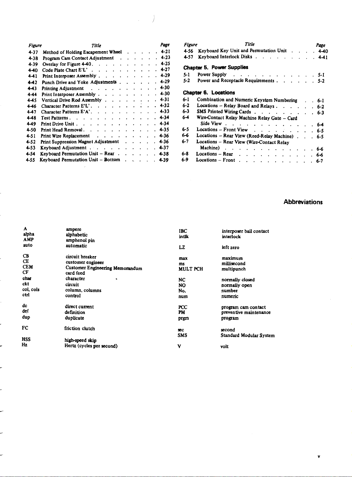
Figure Title
4-37 Method of Holding Escapement Wheel
4-38 Program Cam Contact Adjustment
4-39 OverlayforFigure4-40.
4-40 Code Plate Chart E'L'
441 Print Interposer Assembly
442 Punch Drive and Yoke Adjustments
4-43 Printing Adjustment
4-44 Print Interposer Assembly
445 Vertical Drive Rod Assembly
4-46
CharacterPatternsE'L1.
447 CharacterPatternsE'A'.
448 Test Patterns.
449 Print Drive Unit
4-50 Print HeadRemoval.
4-51 Print Wire Replacement
4-52 Print Suppression Magnet Adjustment
4-53 Keyboard Adjustment
4-54 Keyboard Permutation Unit - Rear
4-55 Keyboard Permutation Unit - Bottom
.......
.......
....
.....
....
.....
....
...
....
....
.....
....
.....
...
.....
.
....
....
.....
.....
.
....
.....
.....
.
. ; .
.....
....
....
....
....
...
.....
....
.
.....
Page
.4-21
4-23
4-25
.4-27
4-29
4-29
.4-30
4-30
4-31
.4-32
4-33
.4-34
.4-34
.4-35
.4-36
.4-36
4-37
.4-38
.439
Figure Title
4-56 Keyboard Key Unit and Permutation Unit
4-57 Keyboard Interlock Disks
Chapter
5-1 Power Supply
5-2 Power and Receptacle Requirements
Chapter
5.
Power
Supplies
..........
6.
Locations
Combination and Numeric Keystem Numbering
-
Locations
SMS Printed Wiring Cards
WireContact Relay Machine Relay Gate - Card
Side View
Locations
Locations - Rear View (Reed-Relay Machine)
Locations - Rear View (Wire-Contact Relay
Machine)
Locations - Rear
Locations
Relay Board and Relays
...........
-
Front View
...........
-
Front
.......
....
....
.......
.......
.........
.........
. .
. .
Page
440
441
. .
.
Abbreviations
A
alpha
AMP
auto
CB
CE
CEM
CF
chat
ckt
col, cols
ctrl
dc
def
dup
HSS
Hz
ampere
alphabetic
amphenol pin
automatic
circuit breaker
customer engineer
Customer Engineering Memorandum
card feed
character
circuit
column, columns
control
direct current
definition
duplicate
friction clutch
high-speed
Hertz (cycles per second)
skip
IBC
intlk
LZ
max
ms
MULT PCH
NC
NO
No.
num
FCC
PM
Prgm
sec
SMS
v
interposer bail contact
interlock
left zero
maximum
millisecond
multipunch
normally closed
normally open
number
numeric
program cam contact
preventive maintenance
ProkTm
second
Standard Modular System
volt
Page 10
5225-3357-3
FES: SS234069
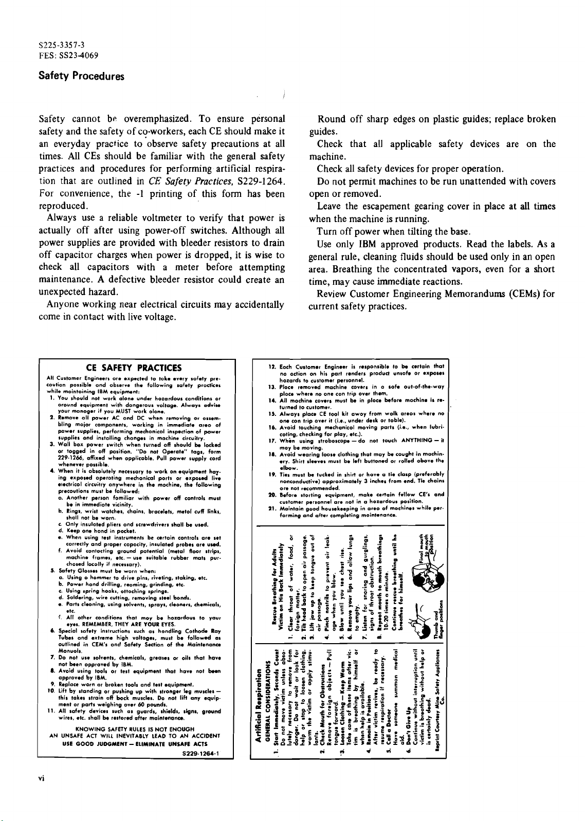
Safety Procedures
Safety cannot be overemphasized. To ensure personal
safety and the safety of co-workers, each CE should make it
an everyday practice to 'observe safety precautions at all
times. All
CEs should be familiar with the general safety
practices and procedures for performing artificial respira-
tion that are outlined in
For convenience, the
CE
Safety Practices,
-1
printing of this form has been
S229-1264.
reproduced.
Always use a reliable voltmeter to verify that power is
actually off after using power-off switches. Although all
power supplies are provided with bleeder resistors to drain
off capacitor charges when power is dropped, it is wise to
check all capacitors with a meter before attempting
maintenance. A defective bleeder resistor could create an
unexpected hazard.
Anyone working near
elect~ical circuits may accidentally
come in contact with live voltage.
12.
All Cu~tomer Engineers ore .xp.cted to toke every sofety pre.
CE SAFETY PRACTICES
caution po~~ible ond observ. the following safety procticas
while mointoining IBM equipmant:
1.
You should not work alone undar
oround equipment with
your monoger if you MUST work olon..
2.
Remove oll power AC ond DC when removing or ossembling moior components, working in immediate areo of
power supplies, performing mechonicol inspection of power
supplies ond
3.
Wall box power switch when turned off should be locked
or togged in off position. "Do not
229-1266,
whenever possible.
4.
When it is
ing exposed
electrical
precautions
o. Another person
b. Rings, wrist watches, chains, bracelets, met01 cuff links,
c. Only
d. Keep one hond in pocket.
e.
f. Avoid rontocting ground potential (metal floor strips,
5.
Safety Glos~es muat be worn when:
a. Using o hommer to drive pins, riveting, stoking, etc.
b. Power hond drilling, reoming, grinding, etc.
c. Using
d. Soldering, wire cutting, removing
e. Ports cleoning, using solvents, sprays,
f.
6.
Special softly instructions such as hondling Cothode Ray
Tubel ond extreme high voltogea, must be followed
outlined in CEM's ond Safety Section of the Maintenance
Monuols.
7.
Do not
not been
8.
Avoid wing tools or test equipment thot hove no1
approved by IBM.
9.
Replace worn
10.
Lift by standing or pushing up with stronger leg muscles
this tokes strain off bock muscles. Do not liH any equipment or ports weighing over
11.
All safety devices such as guards, shields, signs, ground
wires, ctc. shall be restored ofter maintenonu.
AN UNSAFE ACT
USE
instolling chonges in machine circuitry.
ofixed when opplicoble. Pull power supply cord
absolutely
necessary to work on equipment har
operating
circuitry anywhere in the mochine. the following
must be followed:
immediate
be in
sholl not be worn.
insulated
When u~ing test
correctly
machine
chased
.tC.
All other wnditbns thot moy be ho~ordous to your
eyes. REMEMBER, THEY ARE YOUR EYES.
use
KNOWING SAFETY RULES IS NOT ENOUGH
GOOD
fomiliar with power off controls must
vicinity.
pliers ond screwdrivers shall be used.
instrument^
and proper copocity, in~ulated probes ore uud.
frames, etc. - use suitable rubber mots pur-
locolly if necessary).
apring hook,, ottoching springs.
solvents, chemicals, greases or oils that hove
opproved by IBM.
ar
broken tools and test equipment.
WILL INEVITABLY LEAD TO AN ACCIDENT
JUOGMENT - ELIMINATE UNSAFE ACTS
hazardous
dangerous
mcchonical ports or expo~d lire
be artoin controls are set
60
pounds.
conditions or
voltage. Always adrim
Operat." togs, form
steel bond*.
cleaners.
chemicals,
b..n
S229-1264-1
01
-
Each Customor Enginoer in
no
hozards to customer personnel.
13.
Ploce removed machine covers in o sofe out-of-the-way
ploce where no one con trip over them.
14.
A11 mochin. covers mull be in ploce before mochino is returned to
15.
Always CE tool kit awoy from wolk oreos where no
one con trip
16.
Avoid touching m.chanicol moving ports (i.e., when lubricoting, checking for play, etc.).
17.
Whin using stroboscope -do not touch ANYTHING- it
moy be moving.
la.
Avoid wearing loose clothing thot may be cought in machin.
err. Shirt sleeves mu11 be left buttoned or rolled obove the
elbow.
19.
Ties must be tucked in shirt or hove a tie clasp (preferably
nonconductive) opproximotely 3 inches from end. Tie chain1
ore not recommended.
110.
Befor. storting equipment, make certain fellow CE's and
customer personnel ore not in a horardous position.
21.
Maintain good housekeeping in oreo of mochines while performing and after
-
Round off sharp edges on plastic guides; replace broken
guides.
Check that all applicable safety devices are on the
machine.
Check all safety devices for proper operation.
Do not permit machines to be run unattended with covers
open or removed.
Leave the escapement gearing cover in place at all times
when the machine is running.
Turn off power when tilting the base.
Use only IBM approved products. Read the labels. As a
general rule, cleaning fluids should be used only in an open
area. Breathing the concentrated vapors, even for a short
time, may cause immediate reactions.
Review Customer Engineering Memorandums
(CEMs) for
current safety practices.
oction on his part renders product unsofo or exposel
customer.
over
L
.i.i
.
responsible
it (i.4.. under desk or loblo).
completing mointenonce.
rid
h:
"r'd
lo be cortain that
d
Page 11

1.
Section
Reference Data
Figure 1-1 shows machine characteristics for the IBM 29
Card Punch.
1.1 OPERATIONS
The 29 Card Punch operations may be divided, as shown in
Figure 1-2, for troubleshooting. These operations are:
1.
Start and Run:
Establishment of power (electrical and
mechanical) necessary for machine operations. This
includes the operation of the card feed and the
pick-and-hold of the card lever relay.
2.
Interposer Selection:
Engagement of an interposer or
interposers with the punch bail in preparation for
punching.
3.
Escapement:
Advancement of the program drum and of
the escapement-driven feed wheels.
1
Speed:
1
Stacker
Figure
Figure
Chorocteristics
Manuol punching
Manual duplication
Automatic duplication
Skipping
Releasing
Feed from pre-register to detail
station
1-1.
Characteristics
Interposer
Selectian
I I I
1-2.
Operations
Escapement
I
Without Print With Print
20
10 col/sec
20
80
80 col/sec
0.250 sec
/
500
1
500
Description
col/sec
col/sec
col/sec
cords
cards
Punch
Drive
Unit Cycles
I
18
9
18
col/sec
col/sec
col/sec
Chapter
4.
Card Transport:
1.
Reference Data and
Mechanical control of the movement of
the card through the machine.
5.
Punch Drive Cycle:
Controlled rotation of the punch
drive unit index shaft. According to the function, this is
required to punch a hole
or to read a hole
1.2 SEQUENCE OF OPERATIONS
in
in
the card at the punch station
the card at the pin-sense station.
It is essential that the customer engineer be aware of the
correct sequence of operations as they are used
machine function.
1.2.1 Functions
When the function is to punch a character from the
keyboard, the sequence of operations is:
1. Start and run
2.
Interposer selection
3.
Escapement
4.
Card transport
5.
Punch drive cycle
Using the numbers only, the sequence is:
I
1
2
34
5
Showing escapement and card transport (34) side by side
indicates that
'hile 3 causes
4,
they occur at the same time.
Using this notation, the sequence of these operations for
of the functions of the
I
1-3.
29
Card Punch is shown in Figure
The functions shown in Figure 1-3 are the responses of
the machine to the inputs shown here:
I
Key Punch Press any character.
Multiple Punch
Key Skip
Manual Duplicate
Blank Column Manual
Duplicate
Auto Duplicate
Blank Column Auto
Duplicate
Skip: Release, Auto,
Drum if they are down in a column pre
Release, Auto Space
Press the multiple punch key and any
numeric key.
Press the skip key in numeric or alpha-
betic shift.
Press the duplicate key for one or more
columns with no programming.
Press the duplicate key for one or more
blank columns with no programming
and with the machine
Pressing the duplicate key or the reading
"0"
of a
column followed by
program card.
Same as "Auto Duplicate" but for blank
columns with the machine
betic shift.
Press release key if starwheels
grammed
card.
Press release key in a
field but with the starwheels down.
in the program card
"1
2".
Card-tecard skip.
in
"12's" in the
An
"1
nonprogrammed
SerLice
alphabetic
in
in
alpha
are
1"
in a program
Aids
in
shift.
a
up or
any
all
29
FEMM (4169)
1-1
Page 12
Blank
Mult Skip
Key
iunctlon
Punch
Punch Key
First1111I111I
Col
Second
ond
Other
Cols
Figure
Section
2
2
3-4
5
Repsot
forAll
Colr
1-3.
2.
3
3-4
4-5
5
2-5
3-4
Rspmt
Revt
krAll
for
Cycla
Field
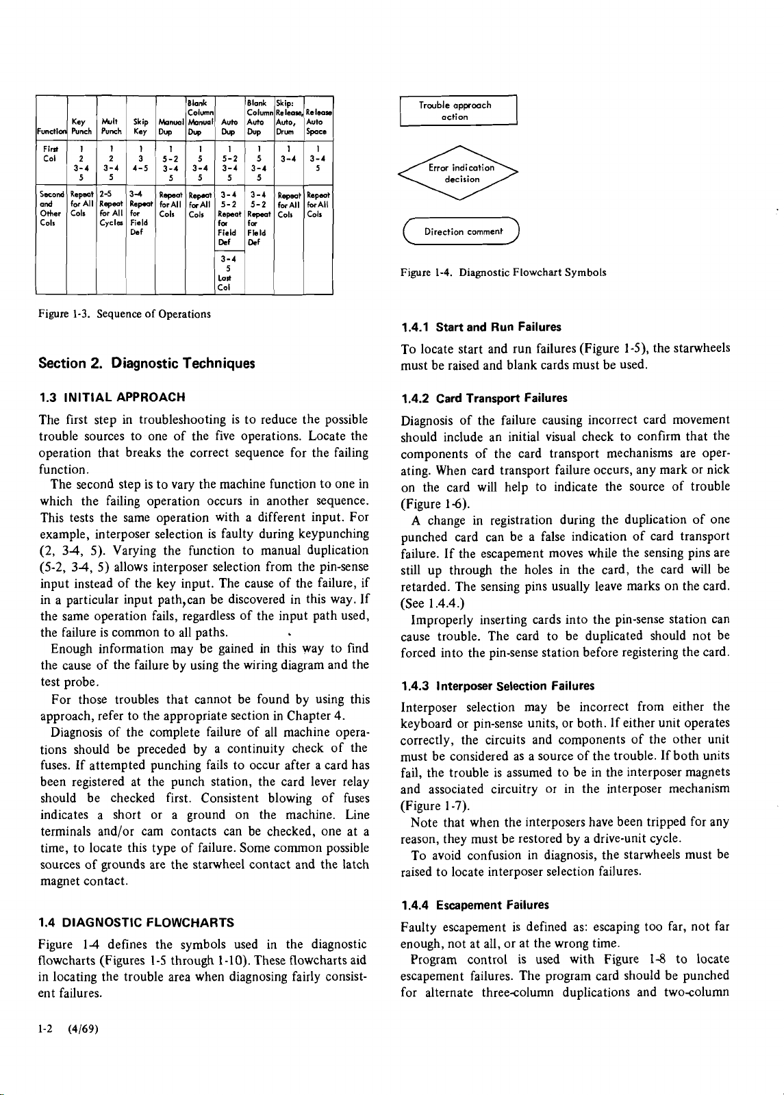
Sequence of Operations
Diagnostic Techniques
Column
knml
~onu.1) Auto
Dy
Dy
5-2
5
3-4
3-4
5555
Revt
Raped
forAll
forAll
Cols
Cols
Dy
5-2
3-4
3-4
5-2
Rspeot
fa
Blank
Column
Auto
Dup
5
3-4
3-4
5-2
R-t
for
Skip:
Release,
Auto,
Dru
3-4
Rspmt
forAll
Cols
Release
Auto
SPu
3-4
Repmt
forAll
Colr
5
(
Direction comment
Figure
1-4.
Diagnostic Flowchart Symbols
)
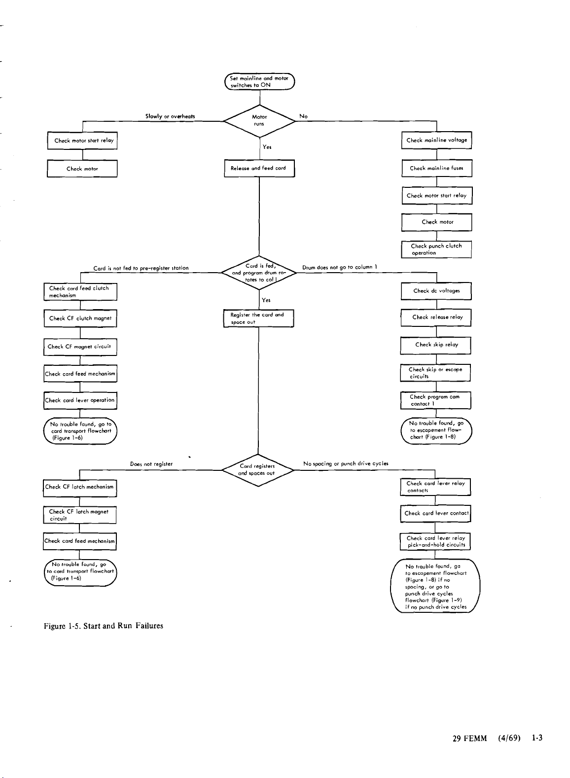
1.4.1 Start and Run Failures
To locate start and run failures (Figure 1-5), the starwheels
must be raised and blank cards must be used.
1.3 INITIAL APPROACH
The first step in troubleshooting is to reduce the possible
trouble sources to one of the five operations. Locate the
operation that breaks the correct sequence for the failing
function.
The second step is to vary the machine function to one in
which the failing operation occurs in another sequence.
This tests the same operation with a different input. For
example, interposer selection is faulty during keypunching
(2, 34, 5). Varying the function to manual duplication
(5-2, 34, 5) allows interposer selection from the pin-sense
input instead of the key input. The cause of the failure, if
in a particular input
path,can be discovered in this way. If
the same operation fails, regardless of the input path used,
the failure is common to all paths.
Enough information may be gained in this way to find
the cause of the failure by using the wiring diagram and the
test probe.
For those troubles that cannot be found by using this
approach, refer to the appropriate section in Chapter 4.
Diagnosis of the complete failure of all machine operations should be preceded by a continuity check of the
fuses. If attempted punching fails to occur after a card has
been registered at the punch station, the card lever relay
should be checked first. Consistent blowing of fuses
indicates a short or a ground on the machine. Line
terminals and/or cam contacts can be checked, one at a
time, to locate this type of failure. Some common possible
sources of grounds are the starwheel contact and the latch
magnet contact.
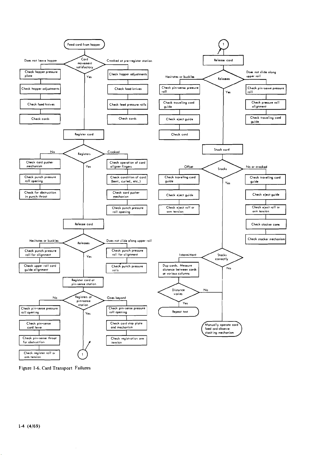
1.4.2 Card Transport Failures
Diagnosis of the failure causing incorrect card movement
should include an initial visual check to confirm that the
components of the card transport mechanisms are operating. When card transport failure occurs, any mark or nick
on the card will help to indicate the source of trouble
(Figure 1-6).
A
change in registration during the duplication of one
punched card can be a false indication of card transport
failure. If the escapement moves while the sensing pins are
still up through the holes in the card, the card will be
retarded. The sensing pins usually leave marks on the card.
(See 1.4.4.)
Improperly inserting cards into the pin-sense station can
cause trouble. The card to be duplicated should not be
forced into the pin-sense station before registering the card.
1.4.3 l nterposer Selection Failures
Interposer selection may be incorrect from either the
keyboard or pin-sense units, or both.
If either unit operates
correctly, the circuits and components of the other unit
must be considered as a source of the trouble. If both units
fail, the trouble is assumed to be in the interposer magnets
and associated circuitry or in the interposer mechanism
(Figure 1-7).
Note that when the interposers have been tripped for any
reason, they must be restored by a drive-unit cycle.
To avoid confusion in diagnosis, the starwheels must be
raised to locate interposer selection failures.
1.4 DIAGNOSTIC FLOWCHARTS
Figure 14 defines the symbols used in the diagnostic
0).
flowcharts (Figures 1-5 through 1-1
These flowcharts aid
in locating the trouble area when diagnosing fairly consist-
ent failures.
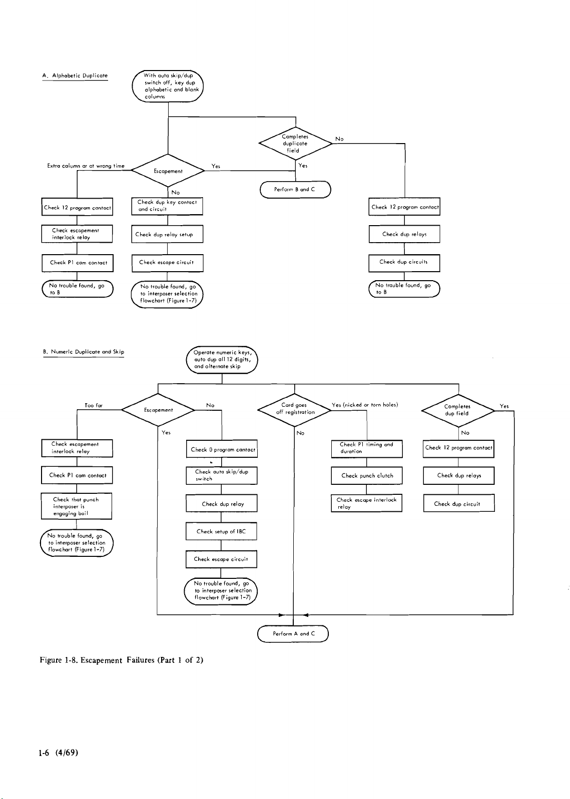
1.4.4 Escapement Failures
Faulty escapement is defined as: escaping too far, not far
enough, not at all, or at the wrong time.
Program control is used with Figure 1-8 to locate
escapement failures. The program card should be punched
for alternate
threecolumn duplications and twocolumn
Page 13
I
(
Check motor start relay
Slowly or overheah No
1
I
Check mainline voltage
Check motor
I
Cord ir not fed to pre-register $totion
Check cord feed clutch
mechanism
Check CF clutch magnet
I
a
Check cord feed mechanism
Check card lever operation
tronrport flowchart
cord
Release ond feed card
a
I
Register the cord and
space out
Drum doer not go to column
Check mainline
a
Check motor stort relay
a
I
I
1
'-4
to ercopement flowchart (Figure
furer
Check motor
I
Check wnch clutch
operation
Check
skip relay
1-8)
I
1
Check CF
latch mechanism
t
(
Check CF latch magnet
Figure
I
1-5.
Start and Run Failures
Doer not register
/
Nospacing
or
punch drive cycles
Check cord lever contact
rl
No trouble found, go
to
ercopement flowchart
(Figure
f
1-8)
rpocing,
or
~unch drive cycler
flowchart (Figure
if no punch drive cycles
if
go to
no
1-91
29
FEMM
(4169)
1-3
Page 14
Feed card from hopper
+
Doer
no1
leave hopper
Check hopper pressure
plate
Check hopper adjustments
movement
$atisfactory
Crooked ot pre-register
Check hopper adjustments
-
Check feed knives
I
I
Check feed pressure rolls
station
I
Hesitater
or
buckln upper rail
Check pin-senre preuure
Check troveling card
Check eject guide
1
Release cord
Releeer
1
Don not slide along
Check pin-$ewe prerrvre
Check
prnsure roil
troveling card
Check
Register card
a
Regirterr
mechanism
punch throot
Heritat-
nlignment
I
I.
pusher
or
buckles
No
Releme card
I
I
I
Check cord
roll opening
Check for obstruction Check card pusher
in
Check punch pressure
roll for
I
Check pin-senre prerwre
I
roll o~enina
Crooked
Check operotion
oligner fingers
(bent, curled,
roll opening
-oes not slide
-7
Goes beyond
I
Check pin-sense pressure]
roll opening
along
I
of
cord
etc.)
upper rail
Check card
CI
Stock cord
u
Offset
Check
trwcling card
guide guide
I
Chcck eject guide
Check eject roll or
Dup cards.
at
various
columns
Repeot test
m
Measure
I
Stocks
\
No
or
crooked
Check
troveling cord
I
Check eject gvide
Check
eject
roll
Check stocker cons
u
Check stacker mechonirm
D
I
or
Figure
1-6.
Card
Transport Failures
I/
Check
regirtrotion orm
feed
ond
observe
stacking mechanism
Page 15

Check interposer relotch
a
and olphobatic
character
keys
Check keyboard restore
Check interposer
Check pin-sere contoch
relotch
v
Check cornmar bar
=?
Check throot plates and
selected
Check kybord contoch
No
1
Check mtore circuit
a
Check interpan magnet
Check inkrpoler
Check keybod shift ckt
w
Check
for
mopat impulse.
no
~ulre, proceed
If
to
Check pin-tare contoch
+
Check rming pin
=7
Check cod regirtrotion
Figure
1-7.
Interposer Selection Failures
29
FEMM
(4169)
1-5
Page 16
A. Alphabetic Duplicate
switch off. kev duo
(
olphobetic and blank
.,,
)
Extra column
Check
Check PI cam contact
0. Numeric
Check escapement
interlock relay
or
12 program contact
Duplicate
Too far No Yer (nicked
ot wrong time
and Skip
and circuit
Check
dup reloy retup
Check
escape circuit
to interposer selection
flowchart
(Figure 1-7)
Yes
Yer
auto dup 011 I2 digits,
Check 0 pragrom cantoct
Perform
B ond C
No
Check
dup relays
a
Check dup circuits
-
No
trouble found, go
(-1
or
torn holer)
Check PI timing and
duration
Check 12 program contoct
Check
PI cam contact
Check that punch
interposer is
engaging bail
I
to interposer selection
flowchart (Figure 1-7)
Figure
1-8.
Escapement Failures (Part
auto rkip/dup
Check
switch
dup reloy
Check
I
Check retup of IBC
I
-
I
Check ercope circuit
interpmer selection
to
flowchort (Figure 1-7)
1
of
2)
I
Perform A and C
C
Check
Check
escape interlock
relay
punch clutch
Check dup relor
Check dup circuit
Page 17
C.
Ksv
Check FC torque
Punch
I
I
Tm
far
Perform
A
and
No
Check
FC
torque
or
mognet
B
Check escape
escape
I
mechanism
Check drive
gsa
train
+
onolyre original
foiling condition
Figure
1-8.
Escapement
skips through column 38. This is followed by a 25column
skip (ending
duplication, a
80.
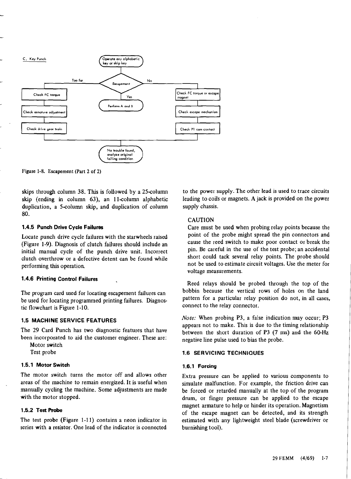
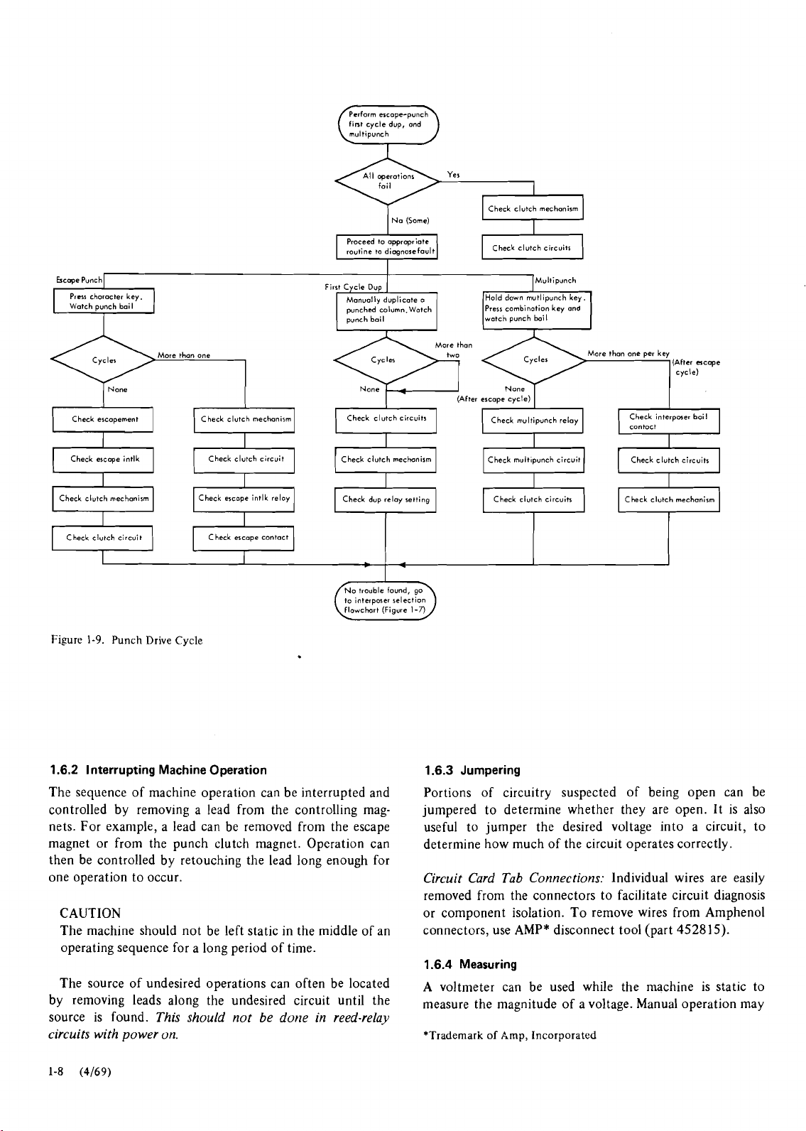
1.4.5 Punch Drive Cycle Failures
Locate punch drive cycle failures with the starwheels raised
(Figure 1-9). Diagnosis of clutch failures should include an
initial manual cycle of the punch drive unit. Incorrect
clutch overthrow or a defective detent can be found while
performing this operation
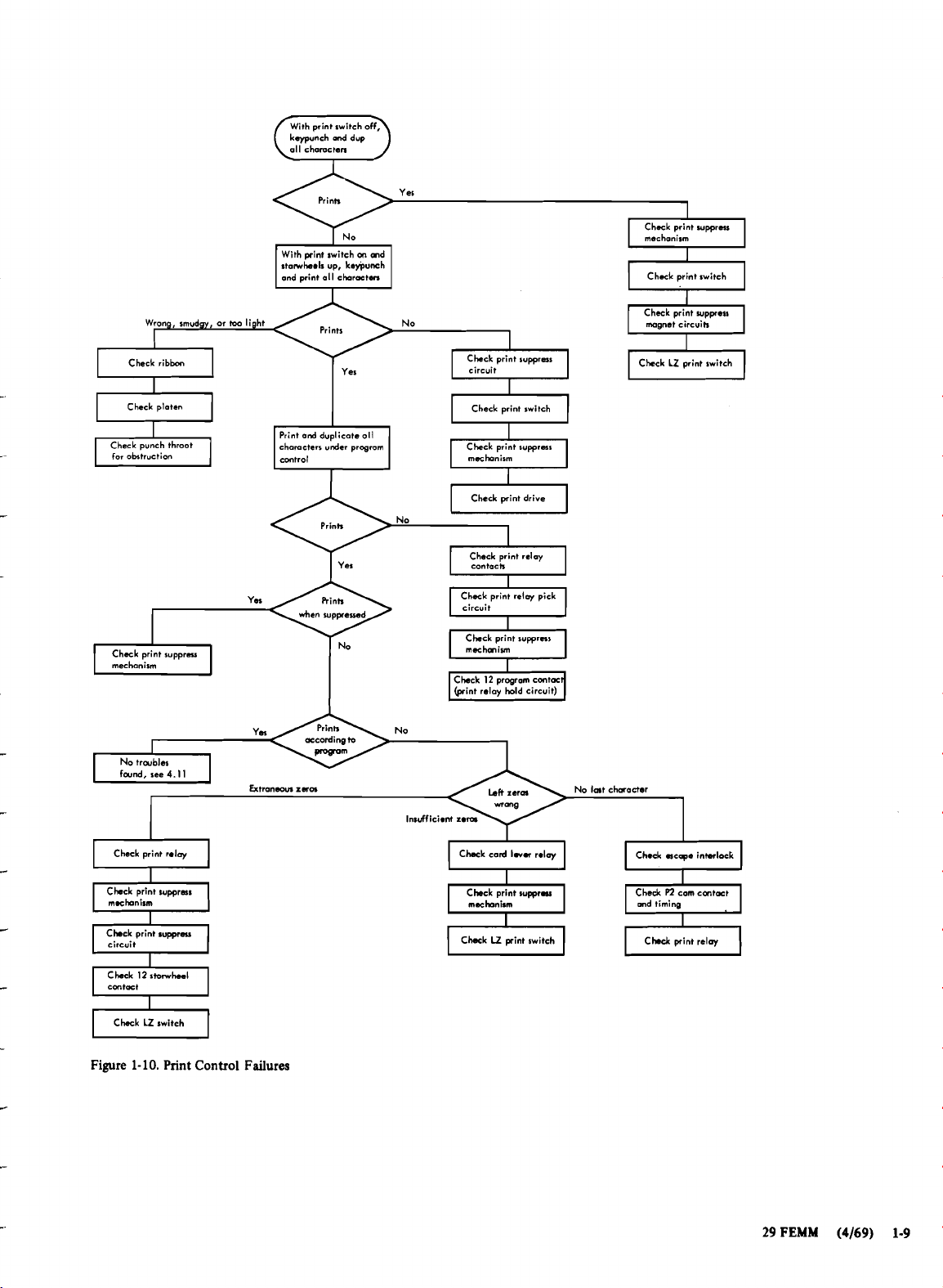
1.4.6 Printing Control Failures
The program card used for locating escapement failures can
be used for locating programmed printing failures. Diagnostic flowchart is Figure 1-10.
1.5 MACHINE SERVICE FEATURES
The 29 Card Punch has two diagnostic features that have
been incorporated to aid the customer engineer. These are:
Motor switch
Test probe
(Part
2
of
2)
in
column 63), an llcolumn alphabetic
Scolumn skip, and duplication of column
PI
cam contact
Check
to the power supply. The other lead is used to trace circuits
leading to coils or magnets. A jack is provided on the power
supply chassis.
CAUTION
Care must be used when probing relay points because the
point of the probe might spread the pin connectors and
cause the reed switch to make poor contact or break the
pin. Be careful in the use of the test probe; an accidental
short could tack several relay points. The probe should
not be used to estimate circuit voltages. Use the meter for
voltage measurements.
Reed relays should be probed through the top of the
bobbin because the vertical rows of holes on the land
pattern for a particular relay position do not, in all cases,
connect to the relay connector.
Note: When probing P3, a false indication may occur; P3
appears not to make. This is due to the timing relationship
between the short duration of P3
(7
ms) and the 60-Hz
negative line pulse used to bias the probe.
1.6 SERVICING TECHNIQUES
1.5.1 Motor Switch
The motor switch turns the motor off and allows other
areas of the machine to remain energized. It is useful when
manually cycling the machine. Some adjustments are made
with the motor stopped.
1.5.2 Test Probe
The test probe (Figure 1-1
series with
a
resistor. One lead of the indicator is connected
1)
contains a neon indicator in
1.6.1 Forcing
Extra pressure can be applied to various components to
simulate malfunction. For example, the friction drive can
be forced or retarded manually at the top of the program
drum, or finger pressure can be applied to the escape
magnet armature to help or hinder its operation. Magnetism
of the escape magnet can be detected, and its strength
estimated with any lightweight steel blade (screwdriver or
burnishing tool).
29
FEMM
(4169)
1-7
Page 18
fint cycle dvp, ond
multipunch
I
Na
(Some)
v
Prcsr
character
key.
Cycler
Check ercopement Check clutch rnechanirm
Check escope intlk
clutch mechanism
Check
a
Check clutch circuit
Figure
1-9.
Punch Drive Cycle
Check escape contact
routine to dimnose fault
punched column.Watch
punch bail watch punch boil
I
1
Check clutch circuits
Check clutch mechanism Check
Check dup relay setting Check clutch circuits Check clutch mechonirm
to interposer
flowchart
(Fioure
relection
1-n
I
Check clutch circuits
Prerr
combination key
(After ercape cycle)
(
Check multipunch relay
multipunch circuit Check clutch circuits
Multipunch
and
I
More
I
than
one
per key
Check interpaer bail
Ic~"toCt
cycle)
I
1.6.2 Interrupting Machine Operation
The sequence of machine operation can be interrupted and
controlled by removing a lead from the controlling magnets. For
example, a lead can be removed from the escape
magnet or from the punch clutch magnet. Operation can
then be controlled by retouching the lead long enough for
one operation to occur.
CAUTION
The machine should not be left static in the middle of an
operating sequence for a long period of time.
The source of undesired operations can often be located
by removing leads along the undesired circuit until the
source is found.
This should not be done in reed-relay
circuits with power on.
1.6.3 Jumpering
Portions of circuitry suspected of being open can be
jumpered to determine whether they are open. It is also
useful to jumper the desired voltage into a circuit, to
determine how much of the circuit operates correctly.
Circuit Card Tab Connections:
Individual wires are easily
removed from the connectors to facilitate circuit diagnosis
or component isolation. To remove wires from
connectors, use AMP* disconnect tool (part
1.6.4 Measuring
Amphenol
452815).
A voltmeter can be used while the machine is static to
measure the magnitude of a voltage. Manual operation may
*Trademark of Amp, Incorporated
Page 19
kypunch
and
all chamctan
With print switch
stamheals up, ke+unch
I
ad print al; ~horiton
dup
Prink
on
md
1
Chock print
mechanism
I
Chock print switch
wppms
I
Wrong, smudgy, or
Check ribbon
I
Check platen
Q
for
obstruction
Chock print supprau
mechanism
No troubles
found, see
4.11
toa
light No
chomcterr under progrom
control
Ym
No
Ym
Extranwm
xua
No
No
I
Check print
circuit
suppras
I
Check print switch
Q
Check pint drive
Check print relay
contach
I
Chock print relay pick
circuit
I
Check print suppress
mochmim
Check
(pint relay hold circuit)
I
12
program contac
f-l
No lmt chaacter
Check print wpposs
magnet circuih
Check print relay
-
Check print suppress
Cbck print suppress
I
circuit
Check
I
Ckk
Figure
1-
I2
LZ
10.
stowh..l
switch
I
I
Print Control
Failures
Invufficient zem
Chak card
a
Chak
m
Iwu
U
print switch
relay
Check
ac-o interlock
a
CW pint relay
m
29
FEMM
(4169) 1-9
Page 20

S225-3357-3
FES:
SS234069
Figure
1-1
1.
Test Probe
be performed to determine the timing of circuit breakers.
The voltmeter can also be used while the machine is
operating, to detect the presence and relative magnitude of
Ihe "Itage'
Remember.
when
measuring power
with no secondary fuse, a short in the secondary indicates
little or no voltage.
A
secondary short may not blow the
primary fuse.
1.6.5 Cycling Manually
Turn the motor switch off. Observe machine functions
while manually operating the escapement gear train and the
punch clutch. This allows voltages to be checked at any
time during the machine cycle.
1.6.6.3
Reed
Relays
When inserting reed relays on the circuit board, care must
be exercised not to exert pressure on the coil portion of the
relay. Pressure exerted on the coil can cause the relay to
flex, and breakage of the glass reed switch may occur. To
prevent this breakage, the relay must be positioned and
pressed on the card with -equal pressure exerted on each of
the plastic ends of the relay (Figure 1-12).
A short caused by a defective part or a slip of the hand
troubleshooting could damage several relays. All
while
relays in the circuit between the short and the line should
be checked because the sudden surge of current could cause
the interceding relay points to weld or develop a
condition.
Do nor remove or replace relays during a
tacking
machine cycle.
If tacking is suspected, do not jar the machine because
the
tacking problem may disappear temporarily.
interchanfe relnys or relay
-
.
types.
If the relay used does not
.-
Do not
have a hold coil, do not put one that has a hold coil in its
place.
DO
reeds
not interchange relay reeds
are
matched
and
should
The individual relay
not
be
interchanged
by
disassembly or use of ones from other relays.
Repeated relay insertions and removals
can
caur
the glass
envelope to break; Berg connectors may lose tension and
cause
intermittent failures. Check connector alignment with
a 0.010-inch feeler gage, aligning it with adjacent
con-
nector.
1.6.6 Interchanging Units
Keyboards, relay boards, or relay gates may be inter-
changed with other machines of the same type and feature
configuration. This can help isolate suspected units when
diagnosing intermittent troubles.
1.6.6.1
Relay Gate
The relay gate in either type of machine is easily remove-
)
able. In the reed-relay machine, slide the relay gate out of
the guide tracks through the slots provided. In the
wire-contact relay machine, first slide one tab out of the
slot, then slide the other tab out.
1.6.6.2
Arc
Suppression
Arc suppression is necessary for the proper operation and
longevity of the reed-relay switches. If trouble is suspected
in an arc suppression network, it
must
be substituted with
another.
CAUTION
Removal of arc suppression for diagnosis can cause
considerable damage as well as faulty operation.
Figure
1-1
2. Reed Relay
1.7 DIFFICULT-TO-ANALYZE AND INTERMITTENT
FAILURES
There are some sources of trouble
Insertion
in
the
29
Card Punch
that cause varying results and are difficult to diagnose.
Among these are:
I
1.
Friction drive totque (too much, too little, or erratic)
Page 21

2. Punch clutch spring (broken, dry or gummy, or loss of
tension)
3.
Punch clutch armature (broken or worn)
4. Punch clutch detent pivot stud (worn or loose)
5. Punch clutch overthrow (too much or too little)
6. Relays (high resistance shorts or hold points burned or
welded)
7.
High-speed cam contacts (binding roller, strap tension,
or loose contact pile-up)
8. Interposer bail contacts (strap tension, air gap, or
contact condition).
An intermittently failing machine should not be returned to
the customer without investigating every suspected cause of
the failure.
1.7.1 Left-Zero Feature
1.7.1.1 Left-Zero Overflow/lncorrect Punchout
Incorrect punchout of left-zero information occurs if the
operator keys-in more digits than the field can contain.
Reed-relay machines continue shifting the bits in the
registers; the first digits keyed-in are lost. Wirecontact relay
machines accumulate the overflow of bits in the first
register.
Examples:
programmed, the operator keys-in 1, 2, 3, 4, 5,
machine punches out
In a reed-relay machine with a five-position field
6.
The
2,3,4,5,6 when the left-zero key is
pressed. In a wire-contact relay machine with a five-position
field programmed, the operator keys-in
1,2,3,4,5,6. The
machine punches 3, 3, 4, 5, 6 when the left-zero key is
pressed.
1.7.1.2 Intermittent Lossof Bits
Common causes for loss of information during read-in or
read-out operations are:
1. Keyboard latch or bail contact adjustments
2. Keyboard restore bail contact adjustment
3.
Error reset contact or backspace switch intermittently
breaking contact
4. Loose slip-on connectors to punch interposer magnet
unit
5.
Loose connectors in 0-volt or 48-volt net to LZ relays
6. Punch
1.7.2 Diagnosis of "Heavy" or Stiff Keyboards
CBs out of adjustment.
To isolate the source of trouble when a keyboard feels
"heavy" or stiff, make the following checks.
1.7.2.1 Key Pressure
Key pressure can be affected by lubrication, by interference
between the
keystem and the cover, or by sluggish interlock
disks.
Lubrication:
used in the correct places. Refer to "Chapter
Interference:
Check to be sure that the proper lubricant is
3."
Check to be sure that the keyb\uttons are
centered within the holes in the cover face.
Interlock Disks:
Check for dirty, magnetized, or oily
interlock disks.
1. With the machine on, press the P-key.
2. Using a gram gage, operate the P-key; 55 to 65 grams
should be read. Note the actual pressure required to
operate the key.
3. Press the Q-key.
4. Using the gram gage, operate the P-key again. The
grams
pressure required should not exceed 10
more than
the reading noted in step 2.
5. If step 4 failed to meet the requirements specified,
remove the interlock disks.
a. Wash the disks and the race in IBM cleaning fluid to
remove all traces of oil or dirt.
b. Test for magnetism by sliding the disks down an
inclined steel surface; replace all sticking disks.
1.7.2.2 Keyboard Cycle Time
To check for slow keyboard restore:
1. Open keyboard base and place machine in numeric shift
by inserting a card between the numeric
keystem
contacts.
2. Feed a card to column
1.
3. Short latch contact 6 and time the punching of 80
columns. Timing should be approximately 4.5 seconds.
4. If the time exceeds
7
seconds, repeat the punching
operation with one thickness of card inserted between
the keyboard restore magnet armature and the core.
5. If an increase in speed of the punching operation occurs,
adjust the armature-tocore clearance to 0.005 inch. (No
increase in speed indicates a slow machine cycle.)
Note:
Keyboard restore magnet coils are connected in
parallel. A short or open in either coil upsets the balance of
the circuit. Symptoms include slow keyboard cycles,
double punching, or extra spaces.
1.7.2.3 Machine Cycle Time
To check machine cycle timing:
1. Install an
80column autodup program card on the
program drum.
2. With the machine in alphabetic shift, time the automatic
blank
duplication of 80 columns (using
cards). Timing
should be 4 to 4.5 seconds.
3.
If timing exceeds the limit, slow action is due to the
punch clutch, the friction clutch, or the escapement
mechanisms.
29
FEMM
(4169)
1-11
Page 22
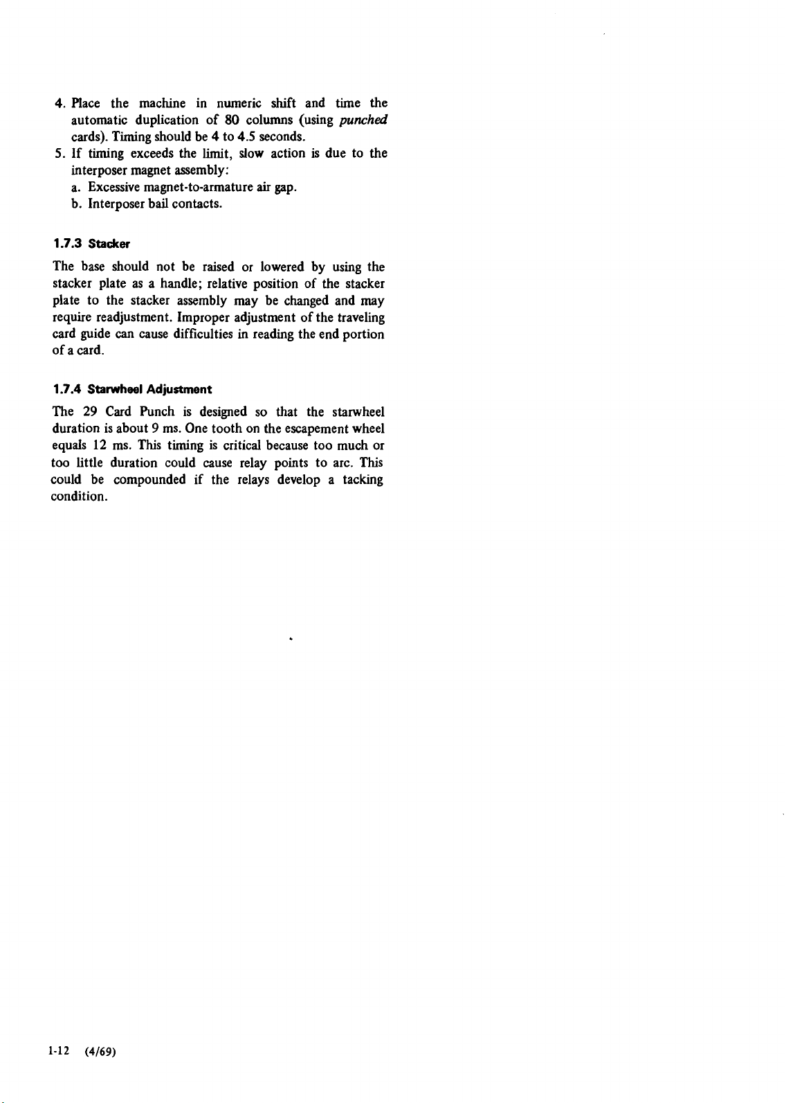
4.
Place the machine in numeric shift and time the
automatic duplication of
cards). Timing should be 4 to
5.
If
timing exceeds the limit, slow action is due to the
80
columns (using
4.5
seconds.
punched
interposer magnet assembly:
a. Excessive
b. Interposer
1.7.3 Stadter
magnet-to-armature
bail contacts.
air
gap.
The base should not be raised or lowered by using the
stacker plate as a handle; relative position of the stacker
plate to the stacker assembly may be changed and may
require readjustment. Improper adjustment of the traveling
can
card guide
cause difficulties in reading the end portion
of a card.
1.7.4 Starwheel
The
29
duration is about
equals
12
Adjustment
Card Punch is designed so that the starwheel
9
ms. One tooth on the escapement wheel
ms. This timing is critical because too much or
too little duration could cause relay points to arc. This
could be compounded if the relays develop a tacking
condition.
Page 23
Chapter
2.
Console and Maintenance Facilities
1.
Section
2.1 INSTALLATION PROCEDURES
2.1.1 Shipping Material
Basic Unit
1. Visually check for any machine damage before signing
the bill of lading. If machine is severely damaged; notify
your branch office before continuing the installation
procedure.
2. Using
packinglunpacking instructions (part 7331 107),
locate and remove spacers, washers, and screws on base
rubber mounts. Also, remove the two screws in the base
pivot brackets to allow tilting of the base for servicing.
3. Check for loose cables, connectors, and components.
4. Adjust line cord to keep excess cord off the floor.
5.
For Model C machines, refer to Field Engineering
Theory-Maintenance,
Interpreting Card Punch, Model C,
2.1.2 Power
IBM 29 Card Runch Features129
Form 223-2926.
1. Compare voltage requirements with those supplied.
5
Chapter
2.
Turn power on and observe the punch drive for smooth
shows power and receptacle requirements.
operation.
2.1.3 Keyboard Operations
1. Set the following switches:
a. Starwheels raised.
Punchlinterpret - PUNCH (Model C).
b.
c. Auto
d. Auto feed
e. Print
f. Left-zero print
skip/dup - OFF.
-
OFF.
-
OFF.
-
OFF.
2. Put cards in the hopper.
3. Press release key:
a. Column indicator revolves 80 columns and returns
to column 1.
b. No cards feed from the hopper.
4. Press register key. Card feed cycle occurs, but no cards
feed from the hopper.
5.
Press and hold feed key. Two cards feed from the
hopper.
6.
Press A through Z and 0 through 9 keys.
Press each key twice to detect binding keystems.
a.
b. Hold numeric key while keying numbers.
7. Release and register second card.
8. Set print switch to on position and press all special
character keys.
9. Operate the clear switch. Both cards should feed to the
stacker. No cards feed from the hopper.
10. Compare holes in the cards:
Holes in the cards should compare with the keys
a.
pressed in steps 6 through
Machine with print feature prints special char-
b.
8.
acters in corresponding columns.
1 1. Check registration by using a card gage.
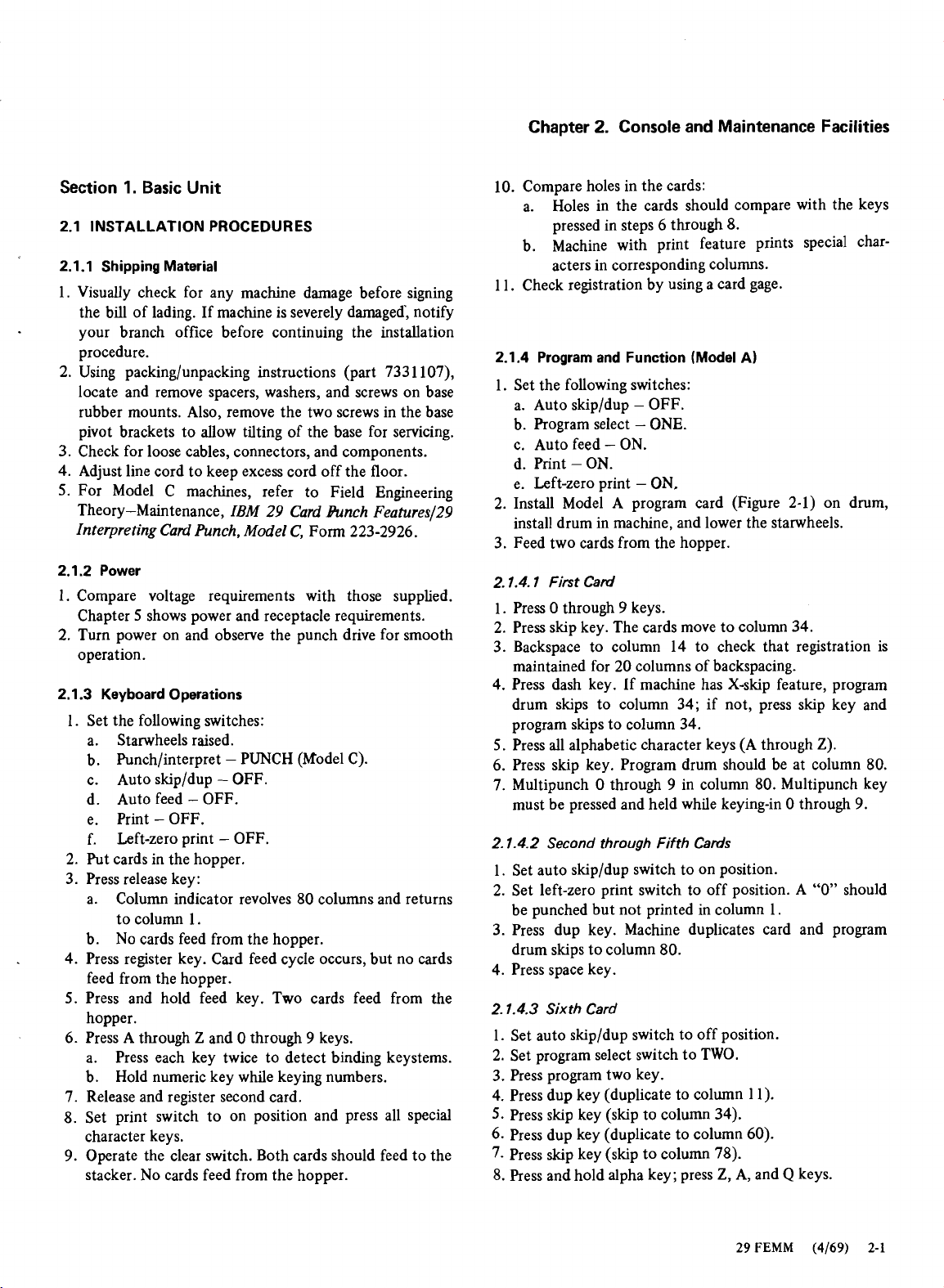
2.1.4 Program and Function (Model A)
1. Set the following switches:
a. Auto
b. Program select
c. Auto feed
d. Print
e. Left-zero print
skip/dup - OFF.
-
ONE.
-
ON.
-
ON.
-
ON.
2. Install Model A program card (Figure 2-1) on drum,
install drum in machine, and lower the starwheels.
3. Feed two cards from the hopper.
2.1.4.1
First Card
1. Press 0 through 9 keys.
2. Press
skip key. The cards move to column 34.
3. Backspace to column 14 to check that registration is
maintained for 20 columns of backspacing.
4. Press dash key. If machine has x-skip feature, program
drum skips to column 34; if not, press
skip key and
program skips to column 34.
5.
Press all alphabetic character keys (A through Z).
6.
Press skip key. Program drum should be at column 80.
7. Multipunch
0 through 9 in column 80. Multipunch key
must be pressed and held while keying-in 0 through 9.
2.1.4.2
1. Set auto
2. Set left-zero print switch to off position. A
Second through Fifth Cards
skipldup switch to on position.
"0" should
be punched but not printed in column 1.
3.
Press dup key. Machine duplicates card and program
drum
skips to column 80.
4. Press space key.
2.1.4.3
Sixth Card
1. Set auto skip/dup switch to off position.
2. Set program select switch to TWO.
3. Press program two key.
4. Press dup key (duplicate to column 11).
5.
Press skip key (skip to column 34).
6. Press dup key (duplicate to column 60).
7- Press skip key (skip to column 78).
8.
Press and hold alpha key; press Z, A, and Q keys.
29
FEMM
(4169) 2-1
Page 24
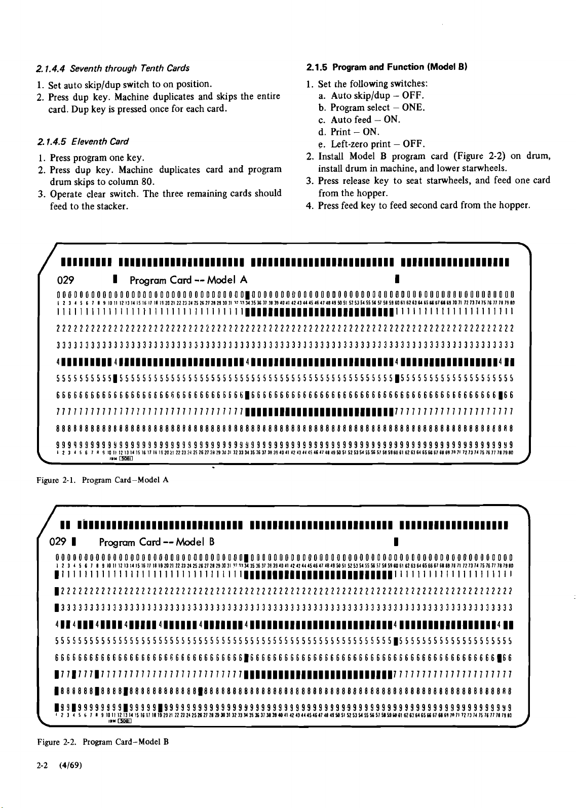
2.1.4.4
Seventh through Tenth Cards
Set auto skipldup switch to on position.
Press dup key. Machine duplicates and
skips the entire
card. Dup key is pressed once for each card.
2.1.4.5
1.
2.
3.
Eleventh Card
Press program one key.
Press dup key. Machine duplicates card and program
skips to column
drum
80.
Operate clear switch. The three remaining cards should
feed to the stacker.
Program and Function
1.
Set rhe following switches:
a. Auto
b.
c. Auto feed
d. Print
skipldup - OFF.
Program select - ONE.
-
ON.
-
ON.
e. Left-zero print - OFF.
2.
Install Model B program card (Figure
install drum in machine, and lower starwheels.
3.
Press release key to seat starwheels, and feed one card
from the hopper.
4.
Press feed key to feed second card from the hopper.
(Model
2.1.5
111111111 11111111111111111111II 1111111111111111111111111 1111111111111111111
B)
2-2)
on drum,
029
000000000000000000000000000000000~0000000~000000000000000000000000000~u000000000
I 2 3 4 5 6 1 19
1
Program Card--Model
IOlII2l3I41516111119202122232425262121293031~~~1Y353ol31394O4142434445464l4849M5I525I5455565l51596O616261r(65r(61M19lOll12l3l4l5l~lll1l91D
A
1
111111111111111~111111111111l1111~~~~~~~~~~~~~~~~~~~~~~~~~~lllllllllllllllllllll
22222222222222222222222222222222222222222222222222222222222222222222222222222222
33333333333333333333333333333333333333333333333333333333333333333333333333333333
4l1llll111
55555555551555555555555555555555555555555555555555555555555155555555555555555555
66666666666666666666666666666666616666666666666666666666666666666666666666666166
4111111111111111111111141111111111111111111111111~
IIBBIIIIIIIIIIIII4
11
777777777777771777777777777177777~~~~11~~~~~~~~~~~~~~~~~~1~777777777777777777777
888888888888888888888888888888888888888888888888888888888888888888888888888888R8
9999999999Y9999999999999999999999Y9999999999999999999999999999999999999999999999
1 2
Figure
/
11
029
000000000000000000000000000000000~0000000000000000000000000000000000000000000000
I 2
1
R
3 4
2-1.
I."
Program Card-Model
9 10 11 I2 13 14 IS I6 11 I8 19 2021 2223
5 6
rn
A
24
25 2621
23
29103l 3233 3351631 3839 4041 4243444346414149M51 52 5354 55565158596061 62636465U616069 loll 12 13 14 15 1611 11 1980
I~IIIIIII~~~~IIIIIIIIIIIIIIII
1
Program Card
3 4 5 6 1 1 9 10 I1 12 I3 I4 I5 16 11 18 19 20 21 22 23 24 25 26 21 21 29 30 31
--
Model
B
17
71
Y
35 36 31 38 39 40 41 42 41 44 45 46 41 48 49
1111111111111111111
1
50
51 52 53 54 IS 56 31 51 59 60 61 62 63 64 65 66 61 68 69 10 11 12 13 14 15 16 11 18 19 10
~11111111111111111111111111111I11~~~~~~~llllll111111111111111
Figure
2-2
2-2.
Program Card-Model
(4169)
B
Page 25
S22.5-33.57-3
FES: SS234069
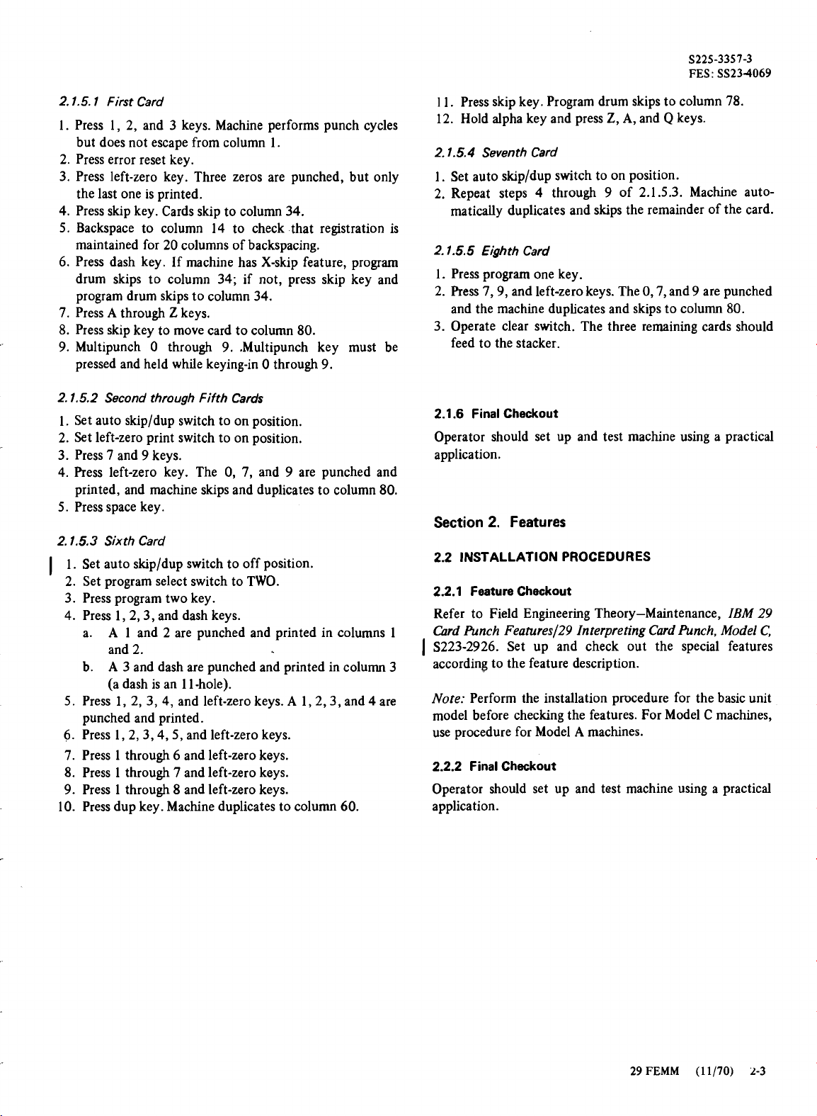
2.1.5.1 First Card
1. Press 1, 2, and 3 keys. Machine performs punch cycles
but does not escape from column 1.
2. Press error reset key.
3. Press left-zero key. Three zeros are punched, but only
the last one is printed.
4. Press skip key. Cards skip to column 34.
5. Backspace to column 14 to check that registration is
maintained for 20 columns of backspacing.
6. Press dash key. If machine has X-skip feature, program
drum skips to column 34; if not, press skip key and
program drum skips to column 34.
7. Press A through Z keys.
8. Press skip key to move card to column 80.
9. Multipunch
pressed and held while keying-in
2.1.5.2 Second through Fifth Cards
1. Set auto skipldup switch to on position.
2. Set left-zero print switch to on position.
3. Press 7 and 9 keys.
4. Press left-zero key. The 0, 7, and 9 are punched and
printed, and machine skips and duplicates to column 80.
5. Press space key.
2.1.5.3 Sixth Card
1. Set auto skipldup switch to off position.
1
2. Set program select switch to TWO.
3. Press program two key.
4. Press
a.
b.
5.
Press 1, 2, 3, 4, and left-zero keys. A 1,2,3, and 4 are
punched and printed.
6.
Press 1,2,3,4,5, and left-zero keys.
7. Press 1 through 6 and left-zero keys.
8. Press 1 through 7 and left-zero keys.
9. Press 1 through 8 and left-zero keys.
10. Press dup key. Machine duplicates to column 60.
0 through
l,2,3, and dash keys.
A 1 and 2 are punched and printed in columns 1
and 2.
A 3 and dash are punched and printed in column 3
(a dash is an 1
9.
1 -hole).
.Multipunch key must be
0 through 9.
1
1. Press skip key. Program drum skips to column 78.
12. Hold alpha key and press Z, A, and
2.1.5.4 Seventh Card
1. Set auto skipldup switch to on position.
2. Repeat steps 4 through 9 of 2.1.5.3. Machine automatically duplicates and
2.1.5.5 Eighth Card
1. Press program one key.
2. Press
3. Operate clear switch. The three remaining cards should
2.1.6 Final Checkout
Operator should set up and test machine using a practical
application.
Section
2.2 INSTALLATION PROCEDURES
2.2.1 Feature Checkout
Refer to Field Engineering Theory-Maintenance,
Chrd Punch Features/29 Interpreting Card Punch, Model C,
1
S223-2926. Set up and check out the special features
according to the feature description.
Note:
model before
use procedure for Model A machines.
2.2.2 Final Checkout
Operator should set up and test machine using a practical
application.
7,9, and left-zero keys. The 0,7, and 9 are punched
and the machine duplicates and skips to column 80.
feed to the stacker.
2.
Features
Perform the installation procedure for the basic unit
checking the features. For Model C machines,
skips the remainder of the card.
Q
keys.
IBM 29
29 FEMM (11170) 2-3
Page 26

Page 27
S225-3357-3
FES: SS234069
1.
Section
The customer engineer's approach to preventive mainte-
nance is important to machine performance and customer
satisfaction. Effective scheduled maintenance is essential
for good machine performance. Time spent systematically
on scheduled maintenance results in complete inspection of
major machine
maintaining a standard machine if normal usage is 40 hours
per week. Refer to Field Engineering Maintenance Manual,
Basic Unit
uriits. Figure 3-1 is a suggested guide for
Motors, Generators, Relays, Circuit Breakers, Test Instruments, Miscellaneous Components,
tional scheduled maintenance information.
3.1 CLEANING
A clean machine is important to good performance. While
cleaning a machine, observe the bearings, cams, linkages,
and other moving parts for rust accumulation. Rust
accumulation indicates wear. Reduction of corrective maintenance is the goal of scheduled maintenance.
S225-3422, for addi-
Chapter
DANGER
Do not permit machines to be run unattended with covers
open or removed.
I
3.3.1 Safety Devices
Check that all applicable safety devices are on the machine.
If they are operating devices, check them every time you
perform a routine PM. Refer to
information.
3.3.2 Electrical Hazards
DANGER
Anyone working near electrical circuits may accidentally
come in contact with live voltage.
Note:
imperative for unconscious victims of electrical shock.
Immediate mouth-to-mouth resuscitation is
3.
Preventive Maintenance
CEMs for current safety
Be alert and careful.
Always disconnect voltage.
3.2 ADJUSTMENT
A properly adjusted machine is more reliable than one that
has had compensating adjustments made for wear or
malfunction in some other area. As part of a PM routine,
check the following adjustments regardless of operating
conditions. A quick check of the same areas is also
recommended at the time of
adjustments for these areas are in Chapter 4.
Friction clutch
Escapement
Feed throat
Punch clutch
CBs
Program unit
3.3 SAFETY
Preventive maintenance also implies the prevention of
accidents to operating and maintenance personnel and
concern for their health and well-being.
each.maintenance call. The
3.3.3 Chemical Hazards
DANGER
Use only IBM-approved products.
general rule, cleaning fluids should be used only in an
open area. Breathing the concentrated vapors, even for a
short time, may cause immediate reactions.
3.4 LUBRICATION
Lubrication points are shown in Figures
Frequency of keyboard lubrication depends on machine
usage and local conditions.
Applicable IBM lubricant part numbers are:
Lubricant Qrcontity Part Number
IBM
#6
IBM
#6
IBM
#23 112
IBM
#23
Silicone
grease
4
ounces
1
pint
1
pound
ounce
Read the labels.
3-2
through
460052
223980
128044
1
1280442
341016
As a
3-7.
29
FEMM
(11170)
3-1
Page 28
S225-3357-3
FES: SS234069
Punch Clutch
Print
ki
1 1 1
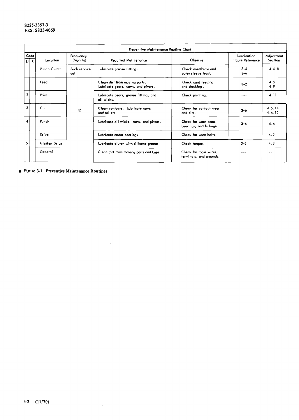
Figure
Drive
3-1.
Preventive Maintenance Routines
Frequency
(Months)
Each service
call
1
Reventive kintemnce Routine Chart
kintenonce
Lubricate grease fitting.
Clean dirt from moving parts.
1
Lubricate gears, cons, and pimts
Lubricate gears, greorc fitting, and
oil wicks.
Clean
contacts.
and rollers. and pits.
I
Lubricate ail wicks, cam, and pivots.
Lubricate motor bearings.
Lubricate clutch with silicone grease.
Clean dirt from moving parts and
Lubricate cam
bore.
Check overthrow and
outer
Check card feeding
1
and stacking.
Check printing.
I
Check for contoct wear
I
Check for worn cams,
bearings, and linkage.
Check far worn belts.
Check torque.
Check far
terminals, and grounds.
Observe
sleeve lead.
loose wires,
Lubrication
Figure Reference
1
I
3-3
---
-
-
3-4
3-6
3-2
3-6
3-6
---
Adjustment
Section Required
4.6.8
4.6
4.2
4.3
---
~
I
Page 29

'/
5
*.
Spring Ends
I
Pin-Sense
Figure 3-2. Lubrication
Lubrication
1.
Die and punches may be lubricated by saturating a
blank card with IBM
the card.
2.
Pin-sense unit may be lubricated by applying two or
three drops of IBM
holes in the
Mechanism
Punches and Stripper
-
Right
Front
Hints:
#
6
oil and punching all columns of
#6
oil to the wicks through the two
pinsense casting. Do not overlubricate.
29 FEMM
(4169)
3-3
Page 30

t
tr.
and
#-a
Block
i
me
Belt
Te
I0
Figure
3-3.
Lubrication - Front
Lubrication Hint:
Silicc
Part
To prevent grease migration to the
Grease
341016
escapement wheel and the friction clutch, apply
Gear
IBM
IBM
#
J
Tn
#2.
23
grease sparingly to the escapement gear train. To prevent
IBM
print suppress armature from sticking, apply
#23
grease sparingly to pivot and block.
-=YA
\lo
Lubriw
Page 31

S225-3357-3
FES: SS23-4069
Figure
3-4.
Lubrication - Front (Machine Bed Tilted)
Lubrication Hint:
excess grease from the sleeves and collar.
After greasing tha punch clutch, remove
This
prevents
grease from splashing onto the armature and magnet.
29 FEMM (11170)
3-5
Page 32

Figure
3-5.
Lubrication - Rear
Page 33

IBM
nature
'6
th
IBM
/
Pivc
'23
Figure
3-6.
Punch Unit Lubrication
Lubrication
Hint:
Do not oversaturate the felt wicks that
separate the punch drive arms. The
the CBs.
oil
will run down onto
29
FEMM
(4169)
3-7
Page 34

Figure
3-7.
Keyboard Lubrication
Lubrication Hint:
To prevent sticking, apply all lubricants
sparingly on keyboard parts.
Section
2.
Features
Lubrication of features should be performed at the discre-
tion of the customer engineer, using the guidelines in Field
Engineering Theory-Maintenance,
FeatureslZ9 Interpreting Card Punch, Model C,
IBM 29 Card Punch
Form
223-2926.
Page 35

Section
1.
Basic Unit
Procedures outlined for removal and adjustment of the
machine units are intended as guides. Adjustments should
be kept close to the specification, but the procedures
preferred may vary among experienced customer engineers.
4.1 BASE
4.1.1 Diodes
Check diodes for shorts or opens by using an ohmmeter.
4.1.2 Arc Suppressors
Check the arc suppression RC units by substitution, never
by running the machine with the arc suppressors removed.
The RC units are highly efficient at reducing destructive
arc.
Chapter
88
4.
Checks, Adjustments, and Removals
of program drum. Each backspace should cause
escapement wheel teeth to move 1-1/4 teeth past end of
armature.
2. Position backspace switch to operate with 1116-inch
depression of the actuating arm.
4.3 FRICTION DRIVE
4.3.1 Friction Drive Service Check
The friction clutch should provide sufficient torque to
deflect gram gage 275 to 325 grams when measured in the
following manner. Manually escape the machine until the
hole in the escapement wheel is straight up. Use the
blade in the gram gage. Hold the gram gage
in
the left hand
10X
(Figure 4-1) and engage the escapement wheel.
-
CAUTION
Operation of the machine without arc suppressors may
cause considerable damage.
4.2 DRIVE
4.2.1 Drive Motor
Factory lubrication of the motor should last one year, if
normal usage is 40 hours per week.
4.2.2 Drive Motor Belt Adjustments
4.2.2.1 Belt Tension
Pil sparingly.
DANGER
Make sure the starwheels are up when checking torque if
high-speed skip feature
I
is
installed.
Press the release key and place right index finger on the
10X blade. Gradually release the pressure of the left hand
until only the blade prevents turning of the wheel. Read the
gram gage.
Gram tension should be measured and adjusted after the
machine has warmed up.
Elongated motor-mounting holes permit adjustment of belt
tension for
4.2.2.2 Belt Size
Check part number of belt. A different size belt is used
1/4-inch deflection midway between pulleys.
_
----
--..
c---,
when machine has print feature.
4.2.3 Backspace Mechanism Sewice Check
Knurld wrw uwd
Check that 20 consecutive columns of backspacing does not
affect card registration. The actuating arm should be
straight and free of binds so that its spring can return it to
normal position.
To ensure proper backspacing, check escapement arma-
ture adjustments (4.4.1).
4.2.4 Backspace Mechanism Adjustment
1. Position backspace ratchet with its three screws to cause
a card to backspace into column 1 and not into column
Figure
4-1.
Friction Drive Adjustment
29
FEMM
(4169) 4-1
Page 36

S225-3357-3
FES:
SS234069
4.3.2
Friction Drive Torque Adjustment
I
1.
Manually escape the machine until adjusting screw is at
the top.
2.
Turn power off and manually turn belt until hole at top
of housing is aligned with adjusting screw.
3.
Adjust screw for required torque. (4.3.1). Turn screw
clockwise to increase torque; a half-turn changes reading
60
about
4.3.3
grams.
Friction Clutch Removal
1. Remove escapement gearing bracket and friction clutch
adjusting screw.
2.
Drive out spring pin holding clutch assembly on shaft.
Remove clutch and separate hub assembly from housing.
3.
Remove nylon friction ring.
4. Remove friction clutch spring.
5.
Reverse removal procedure for reassembly. Make sure
hub assembly is clean and free of dried grease and oil.
I
1.4
ESCAPEMENT UNIT
4.4.1
Escapement Unit
Service
Check
Check the residual on the left yoke end for wear; clean
dirty points and lubricate armature pivot. Clean oil and dirt
from escapement wheel. Too much torque on the friction
drive may make action of escapement armature sluggish.
The escapement wheel must be free of lubricants. Incorrect
strap tension or improper make-time of the escape armature
contact may cause double spacing or erratic escapement.
The contact operating pin should be free enough to allow
pin to be rotated between the finger tips. A binding or
canted operating pin usually indicates poor adjustment of
the unit.
Add
or remove steel .shim
(port
305271)
0.004"
under core to
to
0.008"
obtain
clearance between armaiure
Note - zero clearance
Arrnohrre touching residual
Figure
4-2.
Escapement Adjustment (Part
1
of
2)
Page 37

Wipe off excess lubricant around escapement armature
pivot. Grease at this point picks up dirt and card chips, and
may cause escapement failures.
Observe the armature while
backspacing. If the armature drags with the movement of
the escapement wheel, the armature pivot spring requires
adjustment.
4.4.2
Escapement Unit Adjustments
1.
Remove escapement magnet unit from machine.
1
2. Make adjustments 1 through 7 in Figure 4-2.
Position membly mounting
bmcket so that armature
escape wheel within one
revolution
i
-J"
\
\
\
\
\\
'
.
--_-
stop
Imert
feeler gage
3.
Replace magnet unit.
8
4. Make adjustments
and 9 in Figure 4-2 (Part 2).
The escapement armature pivot spring must hold the
escapement armature against the yoke at the pivot point as
shown at 2, Figure 4-2. Avoid putting sharp bends in spring
straps while forming
them. The outboard edge of the
armature is notched at a point near the hole for the
operating pin; the end is ground at a
armature must be upright for proper operation.
Armature just clear of escape
wheel
--
armature moy nip teeth
but rotation continues
0.010''
//---
0
/
'
I
\
\
\
\
.
\
\
\
\
\
S225-3357-3
FES: SS234069
Sdegree angle. The
lruert
0.008"
feeler goge
Figure 4-2. Escapement Adjustment (Part 2
of
2)
NO;
made
with
ormature ond yoke
0.009"
behvesn
Page 38

S225-3357-3
FES: SS234069
Escapement Gearing:
Keep escapement gear train lubricated
on machines that use the drum-type friction clutch. Keep
card chips and other foreign matter out of escapement gears
and friction drive. Faulty escapement may be caused by
incorrect torque at the friction drive.
All
gear shafts
protruding through bearing support must be pulled to the
extreme forward position before tightening collars. Be sure
unsealed bearings are capped.
4.5 CARD FEED
4.5.1
Hopper
4.5.1.1 Magazine Springs
Adjustments
Form magazine springs to touch feed bed (1, Figure 4-3).
4.5.1.2
Feed
Knives
Check card feed latch magnet adjustment. When card feed
latch magnet adjustment is correct, manually cycle the card
feed mechanism. With CF latch armature engaged with CF
cam follower arm, adjust both feed knives evenly to give
minimum clearance of 0.015 inch (0.040 inch maximum)
from feed knives to top edge of cards in hopper (2, Figure
4-3).
4.5.1.3 Throat
Adjust throat block (3, Figure 4-3) to place crown in direct
line with top edge of throat knife. Adjust throat knife (4,
Figure 4-3) for an opening of 0.008 to 0.010 inch. If
I
throat is properly adjusted, a 0.008-inch gage should freely
pass in three directions (Figure 4-3) but a 0.010-inch gage
should not.
4.5.1.4 Pusher Plate
I
The card-feed pusher-plate spring (5, Figure 4-3) is adjusted
to have 450-gram tension when one card is in the hopper.
4.5.2
Feed
Clutch Adjustment
1. Adjust magnet yoke adjusting screws (Figure
44)
0.032-inch to 0.036-inch clearance between armature
and yoke at the operating end.
2. Form armature spring to exert tension of 100 to 120
grams in direction of A (Figure 44) and 230 to 250
grams in direction of B (Figure 44).
3. Position CF magnet unit to obtain 0.010-inch to
0.014-inch unlatching clearance between armature and
CF dog when armature is attracted (Figure
4-5).
for
Figure
44
4-3.
Hopper Adjustment
(11170)
Page 39

Figure
Yoke Adiustina Screws
Armature
Spring
A
Grams
4-4.
CF Clutch Magnet Adjustment
0.032"
100
to
Magnet Unit
Mounting
/
120
\
to 0.036"
Screws
Support
,
S225-3357-3
FES: SS234069
I
Figure
4-6.
CF Latch Magnet Adjustment
1132-inch off their supports (Figure 4-6).
2. Position magnet yoke so that lower arm of yoke strikes
armature with a 0.010-inch gage between armature and
magnet core. Tighten screws.
3. Turn backstop screw two full turns counterclockwise
and lock.
\
-
-
-
dH
Figure
4-5.
CF Clutch Adjustment
4. Adjust the two jam nuts on the stacker end of the CF
shaft for 0.003-inch to
5. When previous adjustments are correct, clearance be-
tween ratchet and latched dog will be at least 0.005
inch. If clutch nipping or clutch chatter persists, recheck
spring tension as in item 2, then check timing of card
stop cam shaft. (See
Note:
When the cam follower is rising on the cam after
latchup, the cam shaft and card feed shaft are pushed
backward which allows the clutch dog to drop against the
ratchet.
4.5.3
Card
Feed
4.5.3.1 Yoke and Armature
1. With contacts aligned against contact supports, turn
armature backstop screw until stationary contacts rise
4.5.9).
Latch
Magnet Adjustments
Clutch Latch
0.01 1-inch endplay.
Disk
Note:
Check feed knife adjustment after adjusting latch
magnet.
I
4.5.3.2 Mounting Plate Assembly
1. Provide 3164-inch (0.047-inch) clearance from latch
magnet armature to ear on CF cam follower arm (Figure
46).
2.
At same time, position assembly vertically to provide
0.005-inch to 0.017-inch latching clearance from cam
follower arm to armature tip when armature is attracted.
4.5.4
Hopper-to-Prepunch
4.5.4.1 Card Feed Pressure Roll Service Check
Check for even drag on a card inserted lengthwise down
either side. Rollers should be free of binds, and the two flat
springs should be straight when removed from machine.
Misalignment or uneven tension on pressure
cause uneven feeding of cards.
4.5.4.2 Aligner Finger Service Check
Factory adjustment for the card aligner fingers is 0.035inch to 0.055-inch movement ahead of top card rail. The
card must snap off the card aligner fingers and drop into
position along the top rail before registration. Otherwise,
the first 15 columns may be in-registration and the rest of
the card may be off-registration to the left.
Bed
Service
Checks
roll bar may
29 FEMM (11170) 4-5
Page 40

S225-3357-3
FES: SS234069
4.
Install assembly in machine and recheck adjustment by
a
registering
4.5.5.3 Pressure Rail With Microswitch
card.
Microswitch card levers in the detail station right-hand
pressure rail position and the master station left-hand
pressure rail position are adjusted at the factory to transfer
within the correct gram tension range. Replacement of the
entire pressure
rad and switch assembly is recommended
when any part is faulty. To install the microswitch
assembly:
1.
Position the assembly vertically to provide 23-gram to
31-gram (27-gram to 35-gram for master station) pressure against the card. The contact should be transferred.
2.
Remove the card and check that the contact returns to
its normal position.
Figure
4-7.
45.5
Pressure
Pressure
Rail
Rail
Adjustnmnts
Adjustment
When making the following adjustments, hold the gram
in
gage as shown
Figure 4-7. In
reading and pressure rail movement
this
position, gram gage
can
be simultaneously
observed.
4.5.5.1 Pressure Rail Without Contact
Form pressure rail spring in detail station to exert
23-gram
to 31-gram (12-gram to 20-gram for master station)
pressure on a registered card. Check tension necessary to
move rail away from card evenly.
4.5.5.2 Pressure Rail
1.
Remove card lever contact assembly from machine and
With
Strap
Contact
straighten stationary strap.
2. Hold assembly at the same angle it
(45 degrees) and form operating strap to a contact
gap of 0.015 inch to 0.020 inch (Figure
3. Form stationary strap for
minimum
0.025 inch with 23-gram to 31gxam
has
4-8).
in
contact
the machine
air
rise
(27-
of
to
35-gram for master station) pressure applied at center of
lip on rail.
Figure
4-8.
Pressure
4.5.6
Card
4.5.6.1 Detail Station
Rail
-
Card-Lever Contact
Guide Adjustments
Loosen card guide holding screws and position card guide
1
for 0.020-inch to 0.030-inch clearance to detail card bed
(Figure
Figure
4-9).
Debil
Station
Cord
(dotted
linerhwr
4-9.
Card Guide - Detail Station
Guide
later
style)
0.020"
to
0.030"
Page 41

S225-3357-3
FES: SS234069
4.5.6.2 Master Station
Position master station card guide to obtain 0.013-inch to
0.017-inch clearance to center bed plate at point closest to
eject unit (Figure 4-10).
4.5.9 Card Stop Cam Adjustment
1. Loosen setscrews on index shaft bevel gear.
2. With the CF clutch latched, rotate card stop cam to a
point where cam follower is at the approach but is not
up on rise of cam.
3. With some wink at the meshpoint of the bevel gears,
D
Master Station Card Guide
tighten the setscrews.
4. Check timing by watching eject and register arms to be
I-'
T
0.013" to 0.017"
Figure 4-10. Card Guide - Master Station
4.5.7 Card Registration Service Check
Card
sure that they do not start down again at the end of the
CF cycle. The beveled gears are spot-marked at the
factory so that this timing can be regained after removal
of the feed by simply aligning the marks.
4.5.10 Pressure Roll Service Check
Card registration should be checked every time the machine After a card is registered, turn power off. with the power
is serviced. To improve operation of the
arms, lubricate the roller pivots with
IBM
register and eject
#
6.
off, manually engage card feed clutch and turn the card
feed mechanism. Check to see that the card is released by
10 degrees and gripped again at 60 degrees.
0.004"
Right-Hand Bed Plate
1
4.5.1 1 Preoure Roll Adjustments
Card Pusher
Curd Pusher Cam at 50'
Pusher Arm Stud
Figure 4-1 1. Detail Card Registration
4.5.8 Pusher Arm Adjustment
Arm
Stop
1. Position card pusher arm stop to 0.004 inch below upper
edge of right bed plate (Figure 4-1 1).
2. Pull back pusher arm stud to be sure it does not interfere
with registration.
3. Set registration adjusting
screw for best punching regis-
tration.
Note:
This adjustment is easier if a 114-inch socket is
used to loosen and tighten the adjusting screw lock nut.
4. Set card feed index at 50 degrees and adjust pusher
am
stud for 0.003-inch to 0.008-inch clearance to pusher
am.
4.5.11.1 Punch Station
1. Turn card stop cam until cam follower is on high dwell
of cam (index at 22 degrees to 45 degrees).
2. Adjust eccentric on stop lever cam arm for 0.023-inch to
0.032-inch opening between detail station pressure roll
and large feed roll (1, Figure 4-12).
4.5.1 1.2 Read Station
1. Turn card stop cam until cam follower is on high dwell
of cam (Figure 4-1
2.
Loosen locking screw in pressure roll release lever
2).
(Figure 4-1 2).
3. Twist release pin arm shaft until 0.020-inch to
0.030inch clearance is between read station pressure roll and
large feed roll (2, Figure 4-1 2).
4. Tighten locking screw.
4.5.12 Registration Adjustments
4.5.12.1 Detail Station
Check pressure rail tension before making this adjustment.
1. Loosen registration locking screw (Figure 4-12).
2.
Adjust lateral position of detail pressure roll with the
registration adjusting screw so that card rides against the
guide bar while manual duplication is performed.
3. Tighten registration
locking screw.
4. Adjust upper rail (detail station) to eliminate any
vertical registration skew caused by
nonparalIelism
between the die and stripper assembly and the detail
punch bed.
29 FEMM (11170)
4-7
Page 42

S225-3357-3
FES: SS234069
Lever
Qx
Figure 4-12. Pressure
Roll
Adjustment
Fed
Wheel
0.023"
to
0.032"
Stop
Lever Cam
Ar
\\\
Card
Stop
cbm
Note:
Nonparallelism exceeding
rected at the factory.
I
4.5.12.2
Master
Station
0.025
inch must be cor-
The master pressure roll lever pivot is an eccentric.
1. Loosen setscrew (Figure
4-13)
and rotate pressure roll
lever shaft until card does not pull away from upper rail
when spacing is
2.
Tighten locking setscrew.
3.
Multipunch a card with
performed.
12
through 9 in column
Check the card length and registration on a card gage.
Register the card in the read station and space to column
40.
While holding the card stationary, remove the eject
unit and check that both sensing pins are visible in each
hole.
4.
Adjust the two setscrews in the eject throat plate to
obtain the correct registration.
Note:
In addition to nonnal eject wear and malfunction,
the following conditions may cause the preceding adjustment to vary for successive cards:
Alternating long and short cards
Loose pins in escapement gear train
Bent idler gear shafts in escapement gear train
Improper friction clutch torque
40.
Figure 4-13. Master Station Redstration Adjustment
Page 43

4.5.13
4.5.13.1
On
head, plastic bed plate, and die and stripper; then proceed
with steps
separate feed wheel and shaft using procedure listed in
4.5.13.2, step
with steps 1 through 5.
1. Drive taper pins out of escapement wheel and space gear.
2.
3.
4. Slide shaft back far enough to manually insert, one taper
5. Pull pin and bearing free of the shaft and slip shaft
shaft toward the bearing in the space gearing bracket and
lock the collar. There should be little or no
escapement wheel shaft.
Feed
Wheel Removal and Replacement
Detail Station
machines
Remove collar from escapement wheel shaft.
Slide shaft toward rear of machine and slip off escapement wheel and gear.
pin. Use
casting.
through to the inside base and out the top.
When replacing these assemblies, pull escapement wheel
with print feature, remove chip tube, print
1 through 5. On machines without print feature,
3;
then remove die and stripper and proceed
thls pin to force ball bearing out of the base
endplay of the
9/16"
Space
Armature Pivot Plate
1
/
~rmiture Pivot Plate
Dotted lines
1-
Figure 4-14. Armature Pivot Adjustment
shaw
lakr
3-9/16"
style
,
armature
-4
S225-3357-3
FES: SS234069
I
Note:
Check timing of program cam and sensing contacts,
and check adjustment of backspacer. Check printing and
adjust if necessary.
4.5.13.2
The feed wheel is pressed on as well as pinned to the shaft.
1. Remove eject unit and stacker plate. (Check adjustment
2. Remove pin-sensing unit.
3. Withdraw the taper pin that holds space gear to feed
4. Remove the three collars and outboard bearing plate.
5. Remove friction drive (the pins will push out).
6. Remove clip from read-pressure-roll release arm and turn
7.
To reassemble, reverse the removal procedure. Readjust
stacker plate and pin bail drive link. Remove
each shaft before tightening the three collars.
4.5.14 Card
Replace badly pitted or worn points. Check for worn
operating
Master Station
of traveling card guide so that stacker plate can be
replaced in the same position.)
wheel shaft but do not remove it from the feed wheel.
arm so that feed wheel shaft assembly can be pulled to
front of machine for removing bearing and bearing
adapter.
Pull out feed wheel shaft assembly from the rear.
Feed
Circuit Breaker Service Check
arm
rollers;
.
endplay from
(Side
View)
Figure 4-15. Armature Pivot Adjustment - Side View
4.6 PUNCH DRIVE
4.6.1
l
ndex Pointer Adjustment
With clutch detent back against clutch latch, set index
pointer to 345 degrees. Be sure that pointer clears index
wheel.
4.6.2 Interposer Magnet Adjustment
1. Position armature pivot plate as shown in Figures 4-14
and 4-15.
2. Form armature pivot by lifting tip of the armature until
there is at least 118-inch free movement to the operating
end (Figure 4-16).
4.5.15 Card Feed Circuit Breaker Adjustment
1.
Align
points to make sides and faces of contacts parallel.
2.
Adjust stationary contact for 0.020-inch to 0.025-inch
air
gap on high dwell of cam.
4.6.3 Guide Comb and Bumper Adjurtment
With clutch latched, adjust guide comb and bumper so that
bumper portion holds punch operating arms down against
punch bail. When interposers are hooked under the bail,
29 FEMM (11170)
4-9
Page 44

S225-3357-3
FES: SS234069
Figure 4-1 6. Armature Adjustment
Guide
Comb
and
Bumper
enter their armature notches at 92 degrees and so that
are in the notches at 100 degrees. Space interposer
movement varies from that of the other interposers, but
the interposer should be in its armature notch at 100
4
1
degrees (Figure
2. The heel of the latching end of the interposers has been
rounded to avoid contact with the opposite side of the
notch in the armatures. Shift the magnet unit toward or
away from the interposers to obtain 0.040-inch to
0.050-inch clearance (Figure
The preceding adjustment should result in minimum
unlatching clearance of 0.008 inch for each interposer,
except the space interposer, which can have a minimum
unlatching clearance of 0.005-inch (Figure 4-19).
3.
Adjust eccentric screw on knockoff bail (Figure 4-18) to
cause bail to contact an attracted armature at both ends
of unit between 13 degrees and 20 degrees. If the
eccentricity is insufficient, inspect cam follower for
wear. It may be necessary to pivot entire magnet unit
around armature latching point to bring bail closer to
armatures.
4.
Momentarily attract each armature electrically. The
spring should cause the armature to fall away from the
core. If the armatures hang up when the pick circuit is
broken, they should be replaced; the residual magnetism
causes excessive wear on the knockoff bail.
8).
4-
17).
all
Figure
4-1
7. Interposer Unlatching Clearance
there should be 0.003-inch minimum clearance between
bottom of bail and interposers (Figure 4-17). Check
adjustment by placing the hand on the punch arms to take
up any clearance between top of bail and punch arms; then
trip all interposer armatures. All positions should latch
under the bail.
4.6.4
Punch Interposer Magnet Aosembly Adjustment
The position of the magnet unit affects three interrelated
adjustments: unlatching clearances, reIatching of inter-
posers in their armature notches, and knockoff bail.
1. Install magnet unit with reasonable unlatching clearance
as a preliminary step. Do not overtighten screws because
magnet unit will be readjusted in step 2. Restore
four interposers across the unit. While manually rotating
index clockwise, position magnet unit so that the
unlatched interposers in their downward motion start to
all
but
Guide Comb
x>%
Figure
and
I
'
4-18.
Bumpr
I
>,,
11
I
1
looa
'
92
O
Interposer ReIatching Adjustment
Page 45

0.008"
minimum unlatching
clearance except space
lnterparer
\
Crack
S225-3357-3
FES: SS234069
of
light
Figure
4-19.
Armature Unlatching Clearance
4.6.5
Interposer Bail Contact Assembly Adjustment
Bail-contact assemblies may be removed after removing the
master bed plate or punch drive unit.
1. Both contact assemblies must have equal tension. Form
stationary contact strap to require 30 to 35 grams to
raise it off its support. Forming should be within the
area of the support strap to reflect a true condition. One
method of forming the contact strap is to insert a
straightened paper clip between the strap and its
support. Form contact strap to obtain a point-to-point
contact at outer tip of support strap. When strap is
properly adjusted, a crack of light will appear at tip of
support strap during measurement.
2. With contact assemblies removed, form operating strap
near the mounting to require
20
to 25 grams to close
contacts (Figure 4-20). Place gram gage finger under
phenolic pad with 114-inch overlap when checking
adjustment; 50 to 60 grams should then be required to
close contact and to raise stationary contact off support
strap (Figure 4-21).
3.
Reinstall the contact assemblies and adjust their mounting brackets for 0.017-inch contact gap with all armatures restored.
Figure 4-21.
4.6.6
4.6.6.1 With Print Feature
1.
Remove:
Interposer Bail Contact
Punch Drive Removal and Replacement
Rise
Adjustment
a. Belt guard and punch drive belt.
b. Auxiliary duplicating feature (if installed).
c. Wires to punch drive unit.
d. Two screws in pin-sensing bail drive link.
e. Flexible shaft (if installed).
2.
Unhook print drive spring (Figure 4-22) and trip punch
clutch armature to prevent damage to it. Hold index and
remove screw with left-hand threads from end of punch
shaft. Unscrew grease fitting from mounting plug.
Note:
The next step requires realigning the code plate when
reassembling. Refer to 4.1 1.2.3.
3. Loosen knurled thumb screw or remove slotted clip on
vertical drive rod to relieve tension and remove vertical
drive rod guide plate. Disengage the print rod from the
print arm (Figure 4-22) by applying slight pressure on
drive rod at lower end.
4. Lift print drive mechanism from rear mounting plug.
5.
Remove two screws from each end of drive-unit anchor
bar.
6. Loosen screws in front mounting plug enough to permit
disengaging the plug. Remove rear mounting plug screws.
7. Shake drive unit up and down (bed in vertical position)
to free mounting plugs.
8.
Turn drive unit clockwise and remove from base.
Before reinstalling drive unit, manually push punch
extensions in as far as possible. Reverse procedure to install
punch unit. Align groove in eccentric bearing to mark on
print cam (Figure 4-22). Check printing.
Figure 4-20. Interposer Bail Contact Adjustment
4.6.6.2 Without Print Feature
1.
Remove belt guard and punch drive belt.
2.
Loosen setscrew in reduction housing gear hub and pull
out flexible drive shaft. Use unused position of cable
clamp to hold cable out of the way.
29
FEMM (11170) 4-11
Page 46

S225-3357-3
FES: SS23-4069
Rear
Grooves
should
meet
Spring
Figure 4-22. Print Drive Unit Cam Timing
3. Remove the wires from punch clutch magnet and punch
circuit breakers. Remove the slip-connectors from the
interposer magnets.
4. Remove the two screws in pin-sensing bail drive link. On
reassembly, tighten these screws after punch drive unit is
fastened into position with links extended.
5. Remove the two screws from
eachsend of drive-unit
anchor bar.
6. Loosen the screws in front mounting plug enough to
permit disengaging the plug. Remove rear mounting plug
screws.
7. Shake drive unit up and down (bed in vertical position)
to free mounting plugs.
8. Turn drive unit clockwise and remove from base.
all
Before replacing the unit, be sure
punch interposers
are resting in the center of the armature slots. It is easier to
re-engage the punch operating arms with the punch
extensions if they are pushed in flush with the lower guide
plate.
Figure 4-23. Punch Clutch Magnet
4.6.8
Punch Clutch
Service
Check
4.6.7
Clutch Magnet Adjustment
1.
Position the core with shims (part 305271) for
0.006-inch to 0.012-inch clearance between armature
I
and core with armature attracted (Figure 4-23).
2. Attract the armature and pivot magnet assembly around
its support bracket to obtain 0.003-inch to 0.005-inch
unlatching clearance to the step on the sleeve.
Sleeve Latching Surface Lead Distance:
1. Trip the armature and check the outer-sleeve lead
distance; it should be
118 inch to 3/16 inch. Punch
clutch lockup is possible if 3116-inch outer-sleeve lead
distance is exceeded.
2. While the clutch is unlatched, turn the drive pulley
forward (do not use the index wheel) until the outer
sleeve hits the armature and the index stops. This should
be 325 degrees
+,
10 degrees.
Page 47

Overthrow:
Check for ldegree to 3degree overthrow with
the clutch latched. The clamp should be replaced if the
clamp faces contact when tightened. The clutch spring
should be replaced if it becomes distorted.
4.6.9
Punch Clutch Adjustments
4.6.9.1
Sleeve Latching Surface Lead Distance:
Standard Method
This adjustment
establishes the correct relationship between the clutch
spring and the outer and inner sleeves
(Figures4-24 and
4-25).
1. Loosen the clamping screw. The clamping collar is a
separate part and can be moved independently of the
inner sleeve.
2.
Trip the clutch armature and turn the index wheel (not
the drive pulley) forward until the inner- and outersleeve latching surfaces can be observed.
3. Move the clamping screw to an accessible position while
holding the two sleeves with their latching surfaces
visible.
4. Turn the outer sleeve clockwise against the spring
(Figure 4-25). The sleeve moves very easily in a
counterclockwise direction. Therefore, keep the outer-
sleeve protrusion snug against the end of the spring to
avoid a false indication of the latching surface distances.
5. Position the inner-sleeve latching surface behind the
outer-sleeve latching surface as shown in Figure 4-25,
and keep the clamping screw accessible.
6.
Tighten the clamping screw. While tightening this screw,
press the clamping collar and inner sleeve toward the
machine base, and keep the
duter-sleeve protrusion
against the spring.
Lotchino Surfaces
Outer
Clutch Drive Pulley
Figure 4-24. Punch Clutch Components
/
\
Clamping
Screw
Clutch Spring
Detent Collor
\
Hold in Clockwise
Direction Keeping the Sleeve
Protrusion Snug
Figure 4-25. Punch Clutch Adjustment
Overthrow:
This adjustment times the clutch to the index.
Measurement
Sleeve Lotching Surfoces
Agoinst the Spring
Between
The clamping screw must be loosened so that the shaft can
be turned without disturbing the previously established
relationship between the spring and the inner and outer
sleeves.
1. Loosen the clamping screw approximately
Allow the shaft to be turned inside the spring with
114 turn.
some
resistance, but not so loose that the spring will move
inside the inner sleeve.
2. Turn the index wheel forward until the inner- and
outer-sleeve latching surfaces are driven against the
armature. (If you cannot turn the index
beyond this
point, the clamp is too tight; and it is necessary to
loosen the clamp more.)
3. Continue turning the index wheel forward to
347
degrees, 2 degrees beyond the point where the detent
drops into place. While turning the index wheel, hold
the
inner sleeve against the armature to overcome the
tendency of the sleeve to move backward.
4. Tighten the clamping screw securely.
5.
Check the clutch adjustment (use 4.6.8) and repeat if
necessary.
4.6.9.2
Alternate Method
The abbreviated method can be used to make the adjustment after becoming more familiar with the operation
of
the clutch.
1. Loosen the clamping screw and use the index wheel to
position the sleeve and collar to an accessible location.
2.
Hold the outer sleeve against the spring tip, and set the
inner sleeve for the correct lead.
3. Tighten the collar so that the index can be turned with
some resistance after the sleeves are stopped by the
armature.
4. Turn the index wheel to 347 degrees and tighten the
clamp securely.
5. Check the clutch adjustment (use 4.6.8) and repeat
if
necessary.
29
FEMM
(4169)
4-13
Page 48

4.6.10 Highspeed CB Assembly Service Check
1. Check for loose pile-up screws.
2. Check for binds in rollers, operating pins, and plungers.
Inspect cam surfaces for irregularities due to wear or
dirt. Wipe cam surfaces clean before adding new lubricant. If an abrasive tool is used in removing burned
spots, check the contact make-and-break timing.
4.6.1 1 High-Speed CB Assembly Adjustment
1. Remove the CB assembly from the machine. Shim for
0.027-inch to 0.032-inch contact air gap with plunger
seated against the frame (Figure 4-26).
2.
Form operating strap to require 100 to 150 grams of
pressure, at tip of strap, to close contact.
3.
Form cam-follower spring to require 475 to 550 grams
of pressure to close contacts with 0.020-inch to
0.030-
inch overtravel of cam follower.
4.
Install CB assembly in machine but do not completely
tighten the holding screw. Turn CB to low dwell and
turn adjusting screw to obtain 0.017-inch to 0.023-inch
contact air gap.
4.6.12 High-Speed Cam Removal
1.
Remove print cam if machine has print feature.
2. Remove pin from index and slip it off shaft.
3.
Unhook knockoff-bail arm and pin drive link springs.
4.
Drive taper pins from the two mechanical cam assem-
blies.
5. Loosen setscrews in all circuit breaker cams.
6. Slide shaft toward clutch end until end of shaft clears
rear bearing. It may be necessary to shift clutch magnet
assembly to allow clutch collar to pass clutch magnet
armature. Remove desired cam.
4.6.13 Die and Stripper Service Check
A crayon or pencil deposit sometimes forms on the
underside of the die and can cause drag on the card,
resulting in off-registration punching. These deposits can be
removed with a feeler gage.
A convenient method of lubricating the porous bronze
punch guides is to multipunch several columns of an oiled
blank card.
4.6.14 Die and Stripper Adjustment
Die and stripper clearance is set at 0.020 inch to 0.026 inch
on machines without print feature. On machines with print
feature, clearance should be 0.012 inch to 0.017 inch.
4.6.15 Die and Stripper Removal and Replacement (With
Print Feature)
To remove die and stripper:
1.
Remove
:
a. Printing head.
b. Chip tube by taking out two screws (Figure 427). Be
careful not to lose the pressure roll spring.
c. Front rails.
d. Plastic bed plate.
e. Punch extension cover, nuts, and springs.
CAUTION
On reassembly, do not force the nuts tightly against
the shoulder; this can cause the extension to break
off.
f. Horizontal shift spring.
g. Three mounting screws.
2. Pull print interposer assembly from punch extensions.
CALTTION
Keep horizontal shift slide compressed.
Figure
Overtmvel
475
0.020"
4-26.
should
to
550
gram
to
0.030"
High-Speed Circuit Breaker
give
3. Remove bottom punch extension guide plate. Lift each
punch extension over punch arm and push it into the
die.
4. Remove the two die mounting screws.
5. With left hand on punch extensions, remove unit from
base.
4.6.16 Die and Stripper Removal and Replacement (With-
out Print Feature)
Remove die and stripper. With punch drive unit in machine:
1.
Remove lower punch extension guide. With two or three
2-inch pieces of card between die and stripper, push
punches into the die.
2. Remove chip tube by taking out two screws (Figure
4-27). Be careful not to lose the pressure roll spring.
3. Lift out release pin from die.
4. Remove front pressure rail covers at punch and read
stations (Figure 4-27).
Page 49

5.
Remove plastic guide from top of rear rail. The guide is
flexible enough to be removed without pulling pins, if
care is
used.
6.
Remove space gearing cover.
7. Remove the two bed plate screws in master station bed
plate and lift plate out to the right.
8.
Back out the two holding screws and lift out die and
stripper assembly. Be careful not to pull punches out as
the extensions are pulled past interposer arms.
Do not separate die and stripper unnecessarily. Clear all
card chips away from these assemblies when replacing
assemblies on the machine.
Figure 4-27. Punch
4.6.17
4.6.17.1
Punch Penetration Adjustments
With Print Feature
Bcd
-
Front
View
Satisfactory punching should result. from the print drive
and yoke adjustment in 4.1 1.2.1. The punch and extension
retaining pin must be moved, if additional penetration is
needed. Die and stripper clearance is set at 0.012 inch to
0.017 inch. Current machines use the number-1 hole as a
starting point. As the retaining pin is moved to the next
higher-number hole, 0.010 inch more punch penetration is
obtained.
Note:
Always insert the retaining pin in identically num-
bered holes in both the extension and punch (Figure 4-28).
Figure 4-28. Punch
4.6.17.2
Without Print Feature
and
Extension
The following adjustment eliminates partially punched
holes during the setup process. The heel of the lowest
punch must enter 0.015 inch to 0.020 inch into the die.
Refer to Figure 4-29.
1.
Loosen:
a. Support screws in anchor bar.
b. Holding screws in pin bail links.
c. Drive-unit adjusting-screw lock nut.
d. Holding screw.
2.
At 345 degrees (punch index), trip all punch interposer
armatures. To trip armatures electrically:
a. Disconnect escape magnet to prevent spacing when
interposers are tripped.
b.
Operate detail station card lever.
c. With an interposer bail contact lead, energize each
magne t.
3. With index turned to 126 degrees (punches up), turn the
drive-unit adjusting screw in until a 0.010-inch gage
passes between lowest punch and the die. The punch
adjustment holding screw must be tightened after each
trial.
4.
Remove feeler gage and back off two turns on adjusting
screw. Tighten lock nut.
5.
Turn the two support screws until they rest against drive
unit side frames; tighten lock nuts.
6.
With the punch clutch latched, extend the pin bail drive
links.
Additional travel, when needed, should not exceed
118
turn (0.003 inch) of the adjusting screw per step.
4.6.18
4.6.18.1
Punch Removal and Replacement
With Print Feature
Removal:
1. Remove punch extension covers, nuts, and springs.
2. Loosen knurled thumb screw on vertical drive rod; then
unhook horizontal shift spring.
3. Remove the three mounting screws and pull print
interposer assembly from the punch extensions.
29
FEMM
(4169)
4-15
Page 50

Die
Figure
and
Striwer Unit pivots
\
4-29.
Punch Penetration Adjustment
mounting plugs
on
I
1
Adjusting Screw
Holding Screw
Pin Sensing Unit
CAUTION
Keep the horizontal shift slide compressed.
4.
Remove punch extension lower guide. Punches may be
pulled out by lifting each extension over its operating
arm.
Replacement:
To reinstall the assemblies, slip extension
guide plate off print interposer unit and place it over the
extensions first. The extensions will then
be'equally spaced,
and the yokes will locate themselves freely to the extension. When the interposer unit is being replaced on the
extension, the yokes should be in their lowest operating
position and held there by spring or finger pressure on the
slides.
Note that the toe of the punch is toward the front of the
machine. Be sure that the retaining pin head is on the same
side as the pin retaining plate. Support the punch and
extension on a 6-inch scale to aid in reassembly.
CAUTION
When removing the interposer unit, note that the screw
over the 9-punch drive is shorter than the other screws.
Be sure to reinstall the short screw in the same position.
Placing one of the longer screws in this position will bind
the drive unit.
4.6.18.2
Without Print Feature
Removal:
1. Tilt punch bed to vertical position and remove the
three
screws holding punch-extension lower-guide plate.
2.
Slide plate off its guide pins and punch extensions. Any
punch is accessible by lifting the extension over the
associated punch operating arm, and pulling it straight
out.
Replacement:
When replacing the punch assembly, check to
see that retaining pin head is on same side as pin retaining
plate. Toe of punch should be toward front of machine.
Inserting punch into stripper is easier if it is supported on a
6-inch scale, (hold with a rubber band).
4.6.19 Pin Bail Drive Link Adjustment
1. Loosen the two holding screws in pin bail drive link.
2.
Insert screwdriver blade in square hole between holding
screws. After punch clutch is latched at
345
degrees,
extend the pin operating arm until it rests against its
stop screw.
3.
Tighten holding screws while holding link extended.
4.7 PIN-SENSE UNIT
4.7.1 Pinsensing Unit Service Checks
Improper insertion of master cards by the operator can
cause incorrect reading. If the card is pushed in so far that
it is pressed against the feed and
time, is pulled away from the top guide rail, it will stay
id.ler rolls and, at the same
in
this position after being registered. Most punching in the
first third of the card will fail to read, and some punching
in the rest of the card may also be left out.
Page 51

S225-3357-3
FES: SS23-4069
4.7.1. 1 Card Sensing Contacts
Inspect contacts for burning. Remove card particles and
lint. One broken contact in a pair causes intermittent read
failures.
4.7.1.2 Sensing Pins
Check that sensing pins operate separately. Pins sticking
together cause reading failures by forcing both pins to enter
the hole at the same time.
4.7.1.3 Pin Bail, Drive Link, and Arm Assembly
Inspect guide stud in the rear frame for wear. Adjust link
and lubricate stud if necessary. Check for rust accumulation
or wear.
4.7.1.4 Card Lever
Remove any accumulation of card dust around the card
lever.
4.7.2
Pin-Sensing Unit Adjustments
Contact pressure, throat gap, and contact gap adjustments
are made with unit removed from base.
1.7.2.2 Throat Gap
1. Place eject unit in normal operating position on pinsensing assembly. Hold together with screws if necessary.
2.
Shim
throat pkte (bottom of eject unit) to adjust throat
gap for 0.0 12-inch to 0.02 1 -inch clearance (Figure 4-3 1).
Check 0.012-inch clearance at closest point and 0.021-
I
inch clearance at widest point. Replace throat plates
worn beyond these dimensions. The 0.004-inch shim is
part 12 1397, and the 0.0 10-inch shim is part 4990 1.
Note:
1
4.7.2.3 Contact Gap
Late production units do not use shims.
1. Insert blank card and let pins rest against it.
2.
Remove contact cover and adjust common contact bar
for minimum air gap of 0.020 inch and a maximum air
gap of 0.030 inch (Figure 4-3 1).
4.7.2.4 Pin Bail Arm Eccentric
Normally, it is unnecessary to alter factory adjustment on
pin-bail-arm eccentric stop. If adjustment is necessary,
loosen locking screw and adjust eccentric to stop pin-bail
arm when sensing pins are retracted 0.010 inch to 0.015
inch below surface of separators. Tighten locking screws.
4.7.2.1 Contact Pressure
Before installing a new contact molding, pre-form contact
straps (Figure 4-30).
A
reading board is helpful in forming
contacts evenly.
1. Form contacts as shown in Figure 4-30.
2.
Install contacts on pin-sensing unit.
3. Adjust contact pressure by forming the strap near the
molding to require 20 to 30 grams to move the contact
ftom the common bar.
Push
Molding
Downward
Contoct
I
Molding
Figure 4-30. Sensing Pin Contact Adjustment
Figure 4-31. Pin Sensing Adjustment
29 FEMM
(11170) 4-17
Page 52

S225-3357-3
FES: SS234069
4.7.2.5 Card Lever
With pin bail arm against its stop, position card lever to
clear pin bail by 0.005 inch to 0.010 inch.
4.7.3 Pin-Sensing Unit Removal and Replacement
1.
Remove eject mechanism from top of pin-sensing unit.
Remove release pin that operates eject mechanism.
2. Remove the three screws holding eject front rail, the
nuts beneath this rail, and the two nuts holding stacker
plate to stacker assembly near stacker switch. The plate
can now be removed. (When reassembling, check adjustment of traveling card guide before tightening nuts.)
3.
Disconnect pin bail drive link at its ccupling screws
(Figure 4-29) through hole in rear of punch bed. Do not
remove spring from link-to-drive-unit rear frame.
4. Remove the screw holding the sensing-pin cable clamp.
5. Remove the two screws in top of pin-sensing unit and
lift out unit from top of base.
6. With long-nose pliers, pull out common wire to sensing
contact strip; then slip off connections to individual
terminals. Note that cable is fanned out so that it can be
easily reinstalled.
7.
Reinstall unit in machine with punch index at 345
degrees. Extend pin bail link to bring pin bail arm up
against the stop.
CAUTION
Do not overextend pin bail link because punch drive
can be damaged.
two
4.8.1.2 Pressure Roll Opening
For adjustment of pressure roll opening, see 4.5.1 1.2.
4.8.1.3 Throat
Add or remove shims for a throat clearance of 0.012 inch
to 0.021 inch. (See 4.7.2.2.) Late production units do not
use shims. Replace throat plate when gap is not within tolerance.
I
4.8.1.4 Register Arm Tension
1. Tip bed to vertical position and turn CF index to 30
degrees.
2. Insert strip of card between rolls.
3.
Form paper clip to hook under arm just inside roller,
and hook other end in hole of
4. Form long end of spring to require 200 to 275 grams to
free the card.
4.8.1.5 Ejwt Arm Tension
Use the procedure under 4.8.1.4.
4.8.1.6 Eject Card Guide
The plastic guide should clear the stacker plate by at least
0.016 inch. It can be raised by filing the eject casting
slightly or by shimming the right end of the guide. Forming
the plastic is unsatisfactory because, even if heat is used,
the plastic returns to original condition.
4.9 STACKER UNlT
10X blade.
8. Check to see that
contacts. Be careful that plastic dust
the 9-sensing contact.
4.7.4 Sensing Pin Removal
1. Remove pin-sensing unit from machine.
2. Trip card lever and place pin-sensing unit upside down.
3.
Remove plastic dust cover for sensing pin contacts.
4. Remove the two screws holding contact assembly to
frame and lift it off. This exposes operating ends of
sensing pins. Use care to avoid moving contact bail
because it is possible to lift all sensing pins out of the
separator; considerable time is needed to replace them.
4.8 EJECT UNIT
4.8.1 Eject Unit Adjustments
4.8.1.1 Pressure Roll Registration
Adjust pressure roll lever shaft to align pressure roll with
feed roll and cause proper feeding through read station
(4.5.1 1.2 and 4.5.12.2).
P5 makes
after
and breaks
cdver does not bind
before
pin
4.9.1 Stacker Unit Adjustments
Note:
Check wiring diagram for exact timings on machines
with special features such as variable card length feed.
4.9.1.1 Stacker Timing
With card feed index at 0 degree, time stacker with teeth
that provide the closest measurement to 4-1 1/16 inches
from upper cut in stacker drum to front edge of base. This
Mesh
Gears
far nearest measurement
Figure
t-
Opener Cam
4-32. Stacker
42
Timing
4-1
1/16,'
-4
Page 53

distance should be measured before removal of unit to
prevent changing other adjustments that might be affected
because of a change in timing. Be sure to measure distance
to edge of base and not to stacker bed plate (Figure
4-32).
S225-3357-3
SS234069
FES:
4.9.1.2 Card Pusher Cam
The cam is mounted by screws in elongated holes on the
stacker drive gear. Position cam so that
gr_ipper fingers grip
3/16 inch of the card. Check adjustment with power on
(Figure 4-33).
4.9.1.3 Number- 1 Opener Cams
With stacker plate removed, adjust front opener
73
that gripper fingers just start to open at
4.9.1.4 Number-2 Opener
Cams
degrees.
cams
so
The rear opener cams are positioned so that card is released
when fully stacked but before it is damaged. Check
adjustment with power on.
4.9.1.5 Stacker
Note:
For stacker plates mounted directly to casting (no
rubber acoustic isolators), omit steps
Bed
Plate (Figure 4-34)
1
through 3.
1. Loosen the two hex-head screws securing the stacker
plate mounting bracket to the base. (The bracket, below
Adjust bmper for 0.005" to
0
.OIO1'
Above
Card
Line
Stacker
Plate
Front
0
Figure 4-34. Traveling Card Guide
Parallel
0.003"
L
R~I
toO.007"
the stacker, with the wirecontact relay and arc suppres-
sion mounted on it.)
2.
Adjust the stacker plate mounting bracket so that the
0.050
stacker plate is flush to
inch below the stacker
drum at the card line (top of the card).
3. Tighten the mounting bracket screws.
4.
Insert a card halfway through the eject station
against the master station upper guide rail.
and
7
Clear Card
Figure 4-33. Stacker Adjustment
Lina
.
29 FEMM
[11/70) 4-19
Page 54

S225-3357-3
FES: SS234069
5. Loosen acoustic isolators or mounting screws.
6. Remove the lower stacker card guide.
7. Position the stacker plate parallel to and with 0.003-inch
to 0.007-inch clearance between the bottom of the card
I
and the lower stacker rail (use the support bumpers to
the rear and below the stacker when stacker support
bracket is on the machine).
8.
Tighten the isolators and replace the card guide.
9.
Adjust the traveling card guide bumpers to allow
0.005-inch to 0.01 0-inch clearance between the traveling
card guide and the card when the feed clutch is latched
and
a
minimum of 0.00 1-inch clearance when the card is
stacking. When properly adjusted, the operating noise is
reduced by the rubber bumpers.
4.10 PROGRAM DRUM UNIT
4.10.1 Sensing Assembly Service
4.10.1.1 Card Life
Check
The program card should be changed daily when usage is
heavy. The sensing wheels, in correct adjustment, should
graze the surface of the program card. Improper tension on
the program sensing arms shortens life of the program card.
Worn program cards may cause elusive failures.
4.10.1.2 Drum Interchangeability
Determine interchangeability by checking all drums against
a master drum. Replace worn gripper cam shafts.
2. Make certain that program drum shaft adjustable yoke is
not loose.
3. Check for wear between end of shaft in program drum
and hole in column indicator wheel that locates and
seats drum.
4. Check for excessive
play in the escapement gear train,
while power is off.
5. Test friction drive torque.
6.
Be sure that the plastic safety cover is installed over the
terminals.
Service time on these contacts is greatly reduced if the
method outlined in 4.10.2 is closely followed.
4.10.2 Sensing Assembly Adjustments
With the escapement armature stopping the escapement
ratchet tooth and machine power on, a zero reference point
is established at any single column of the program unit by
using the timing tool, part 453160 (Figure 4-35). The use
of millisecond (ms) notation instead of 1/12 of an
escapement tooth is to aid in determining relationships of
the program unit timing to the escapement during a skip
operation and does not imply using an oscilloscope.
Perform operations in the order shown:
1.
Set the starwheel tension when the contacts are changed.
2. Set the starwheel duration.
3. Use only a starwheel with the correct duration to set the
armlstarwheel timing.
forked
4.10.1.3 Drum Eccentricity
1.
Mount a program card with 4's punched at about
15-column intervals.
2. Space to the columns preceding the punched ones and
observe the distance from the starwheel to the hole.
Variation in the starwheel-to-hole distance is an indication of drum eccentricity and should not exceed 0.003
inch.
4.10.1.4 Sensing Wheels
Wheels must pivot freely. Check for oxide deposit on
pivots, and for proper lubrication. Sensing arm lever must
move freely on its pivot shaft.
4.10.1.5 Sensing Contacts
Contacts should seldom require adjustment. When trouble
is suspected in this area, remember that there are several
possible sources of trouble inside and outside the sensing
unit that may make this adjustment erratic and unstable.
Check the following points before adjusting the sensing
contacts; it may save a callback.
1. Inspect straps and contact screw heads for pits and
nodes.
or the cover screw
Figure
4-35.
Timing Tool
Page 55

4.10.2.1
Starwheel Tension
1. Adjust flat-tip strap type contacts for 50-gram to
60-gram contact pressure, measured at the starwheel
hub, to lift each starwheel off the program card.
2. Adjust barrel-tip strap type contacts for 35-gram to
45-gram pressure measured in the same manner as the
flat-tip strap type.
4.10.2.2
Starwheel Duration
Prepare a program card with each digit punched in every
other column. Check registration with a card gage.
1. Remove common wire and all starwheel wires (12
through 9).
x
2. Using R
10 scale, connect an ohmmeter between
starwheel common and 1 1-starwheel contact.
3. Set timing tool
4. With the
gnd 6-inch scale as shown in Figure 4-35.
1
1-starwheel fully seated in a hole near column
40 of the program card, rotate the escapement wheel in
both directions. Adjust the 1 1-starwheel contact for
9-ms duration as shown in Figure 4-36. (This is a
dynamic adjustment requiring motor drive.) Figure 4-37
is a guide for holding the escapement wheel while
making this adjustment.
5. The remaining starwheels are adjusted to a meter
reading. To calibrate the meter, remove the fiber
Escape Mwernent
u
Zero Reierence Point
11109876543 2101234567891011
*
Mc
*
kor 32nds after the tooth has
passed the escapementannature tip
4-1/2
All Stamheel
Timings
5- 1/2 5- 1/2
be timing tool, part 453160
Figure 436. Program Unit Timing Chart
9
4 8m(Min) 4
or 32nds before the tooth is
,
stopped
by
tkescapementanaturr
I
I
(Ideal) 4-1/2
I
escapement armature return pin and note the meter
reading. Adjust the duration of the remaining starwheels
to match the meter reading of the 1 1-starwheel contact.
Replace the fiber escapement armature return
pin.when
adjustments are complete.
Figure 437. Method of Holding Escapement Wheel
29
FEMM
(4169)
4-21
Page 56

S225-3357-3
FES: SS234069
4.10.2.3 Starwheel Timing
Using the same program card as that used in adjusting
starwheel duration, locate an 11-hole near column 40.
Center the 1 1-starwheel timing by adjusting the forked arm
for 4.5-ms duration on both sides of the escapement wheel
tooth as shown in Figures 4-35 and 4-36. (This is a dynamic
adjustment requiring motor drive
.)
Figure 4-37 is a guide
for holding the escapement wheel while making the
adjustment. Timing the 1 1-starwheel automatically times
the remaining starwheels.
4.10.3 Sensing Assembly Removal and Replacement
4.10.3.1 Program Sensing Unit
Remove program sensing unit as an assembly by taking out
the two screws holding unit to base casting. On machines
where plastic top plate that supports sensing wheel arms is
not pinned, scribe a line along its left edge to ensure proper
relocation; contact duration and timing are easily lost by
removing the top plate. When assembly is reinstalled on
base, the shoulder on sensing unit should seat firmly on
base; a locator pin ensures proper lateral placement. Check
timing of contacts after reinstalling unit.
4.10.3.2 Sensing Contact Straps
Loosen the common plate screws so that tension is taken
off contacts. Be careful not to bend contacts while
removing or installling.
4.10.3.3 Program Shaft Assembly
No timing need be observed when installing a program shaft
assembly. When installing auxiliary duplicate assembly, it
must be timed to the program index. Punch a card in
column 1 and place it on the auxiliary drum. With program
index at column 1, install unit with starwheels reading
column 1.
4.10.5 Program Cam Contacts Adjustment
The contacts are to be timed according to the timing on the
wiring diagram. Timing is set by the adjustable program
cam (Figure 4-38).
4.10.6 Program Drum interlock Arm (Split Hub) Adjustment
1. Raise starwheels.
2. Rotate interlock arm on serrated shaft to operate
program handle switches with 0.002-inch to 0.005-inch
travel remaining before switch plungers bottom.
3. Lower starwheels.
4. Position interlock arm along the serrated shaft for
0.015-inch to 0.020-inch clearance to the top of the
program drum.
4.11 PRINT UNIT
4.1 1.1 Print Assembly Serivce Checks
4.1 1.1.1 Code Plate Lubrication
Keep oil or grease away from back of code plate because
they cause printing failures.
4.17.1.2 Code Plate Projections
Broken or missing projections can be determined easily fo
one specific character.
A
test of other characters will
usually determine if it is a shifting error or a bind.
4.1 1.1.3 Code Plate Return Springs
If the machine is run without plunger, broken wires or code
plate projections occur.
4.10.4 Program Cam Contacts Service Check
With power on and the program drum in column 1, use
feeler gages and place 0.070 inch between the
escapearmature tip and the escape-wheel tooth. The contact
should be made. Place 0.042 inch between the armature tip
and escape-wheel tooth; the contact should be open.
Note:
To allow reverse drum motion, hold contact operating
arms clear of
I
PCC cam.
4.17.1.4 Code Plate Shifting Test
To determine which way the code plate should be shifted
for correct printing, place overlay (Figure 4-39) over code
plate chart Figure
440 and shift it for a particular
character.
If printing troubles occur, this method may help determine whether the trouble is broken wires, damaged code
plate, or improper code plate shifting.
Page 57

Register a card. Space to column 80.
Hold escape wheel as
@
key. Watch br the timing of the card
to card skip
contoct.
Refer to the machine wiring
or
os controlled by the
redjust the program cam contoct timings.
belav. Punch a
jl
diogmm to check
0.035" to 0.055"
operot~ng strop.
Form
Position lever
cam for #I contact arm just dropped off
cam at column 88-1/3 (meosure on ercope
Lever Bracket
bracket or adiustable
air gap(Yl contoct only)
At column
(o)
(b)
/
-w/
obtoin proper moke time, position
To
contact bracket
at column
.r
8nvn1
ur
1:
Adjust the tension on #2 contact operated
strap for 0.005" to 0.025" rise of the
contact from
Turn the lever bracket for 0.015" clearance
(#2
ik
contoct only) of the arm to the contoct pad.
wuth program index
86
for a 0 015' to 0.025'
#I
.
:t rtotionory strop
ruppumo
strap.
support.
/
NC
@I
At column
the contact for.
(a) 0.015" to 0.025"
(b) 0.020" minimum oir gop of the
This
of the
86,
form the support straps of
from
ik
wtll result in the proper make timing
#2
contoct.
/
rnse of the
support strap.
NO
NC
contact
contact
#2 Contact
(outer)
Figure
4-38.
Program Cam Contact Adjustment
Page 58

F~gurc
4-39.
Obcrlay for I-~gure
4-40
29
FEMM
(4169) 4-25
Page 59

Figure 4-40. Code Plate Chart
E'L'
29 FEMM (4169) 4-27
Page 60

S225-3357-3
FES: SS234069
Punch
4.1 1.1.5 Printing Interposers
-
Figure 441 shows the location of the print interposers,
rollers, and slides. Each unit of cam action equals 0.020-
inch motion to its slide. A -1 cam has a 0.010-inch cut
from both sides of the interposer, resulting in a 0.020-inch
motion. A
Figure 441 as a guide to reassemble the print interposer
assembly. The
faces. (The ratio of motion of the slides to the code plate is
10 to
11.)
+4
interposer moves the slide 0.080 inch. Use
+
or - values are etched on the interposer
Extensionc2--
Guide Plate
I
I
I
I
Arm
I
-
Fixed Sto~
Locking Screw
If
Side View
Figure
4-42.
Punch Drive and Yoke Adjustment
Note:
Extend and tighten the pin bail drive link during
reassembly.
Horizontal Slide (inside V~ew)
Figure
4-41.
Print Interposer Assembly
4.1
1.2
Print Assembly Adjustments
Adjustment of one component unit often affects another
unit. Units should be adjusted in the order in which they
appear in the following text.
4.11.2.1 Punch Drive and Print Yoke
Clearance between the yokes and guihes should be 0.015
inch to 0.020
the punch drive unit. This clearance causes rollers to
contact print interposers a minimum of 0.015 inch above
the start of cam action. Because the clearance cannot be
measured, it is obtained as follows:
1.
Oil (IBM # 6) the print interposers.
2. Remove belt guard and punch drive belt to remove
tension on drive unit.
3. Loosen the two screws in the pin bail drive link.
4. Loosen the adjusting screw lock nut, holding screw, and
two support screws in the drive anchor bar (Figure
4-29). Unhook the print drive spring.
5. Rotate the drive unit counterclockwise with the punch
clutch latched until yokes can be felt to bottom on their
inner guides. Turn the adjusting screw in until it touches
the casting; back off 1 to 1-112 turns maximum and
I
tighten the lock nut and holding screw. The two support
screws should be turned in until they rest against side
frames.
6. Reassemble the machine and test punch penetration
with standard codes.
inch,(Figure 442); it is obtained by adjusting
-1
+2
.I
-2
-3
+4
-3
-1
4.1 1.2.2 Code Plate Clearance
1. Start with one 0.003-inch shim (part 305243) and two
0.007-inch shims (part 228296) between the pressure
plate and the shim retaining plate (Figure 443).
Note:
No oil or grease should be on the code plate or
shim retaining plate because shifting troubles occur.
2. Turn the three large pressure plate adjusting nuts
counterclockwise until snug (Figure 443). Lock them in
this position.
3. Check for code plate clearance to wires of 0.028 inch to
0.030 inch. Add or remove code plate shims if necessary.
4.7 1.2.3 Code Plate Alignment (Figures 4-44 through 4-47)
CAUTION
Failure to loosen locking screws during alignment may
result in sheared adjustment screws.
1.
Code plate is aligned with the punch clutch latched up.
Loosen screws on the vertical drive rod guide plate
(Figure 445).
2. Loosen stop-adjustment locking screws and back off
horizontal and vertical stop-adjusting screws (Figure
444).
3.
Unhook horizontal shift spring. Take tension off vertical
shift spring by backing off knurled thumbscrew (Figure
445). Tighten the locking nut.
4. Insert code plate aligning tools.
5. Position both vertical drive studs within the code plate
slots and tighten the locking screws of the vertical drive
rod guide plate (Figure 445).
29
FEMM
(11;70)
4-2r
Page 61

\\
//-Wire Guide
Printing Pressure
'71
Figure
4-43.
Vertical
Shift Spring
Rinting
Adjustment
--.--
Ern
Vertical Print
Interposer
Bar
I
Haizontal-Shift
Spirg
Adiurtment Lockim Screw
Haizontal
Adjusting Screw
@
A
Vertical
Adjusting Screw
Figure
444.
Print Interposer Assembly
Page 62

Vertical Drive
Studs.
printed, refine the code plate alignment (without code plate
stops) as follows:
1.
Position the code plate with the aligning tool, as done in
preceding steps, and tighten the locking screws.
2.
Adjust the vertical position of the code plate by printing
an
8.
Loosen-the vertical locking screw, and turn the
vertical adjusting screw clockwise until unwanted dots
appear. Mark this position. Turn adjusting screw
counterclockwise past a clear
8
until unwanted dots
reappear. Mark this position. Turn adjusting screw to a
point midway between these two positions and tighten
the locking screw.
3.
Adjust the horizontal position of the code plate by
printing a
6.
Loosen the horizontal locking screw and
turn the horizontal adjusting screw clockwise until
unwanted dots appear. Mark this position. Turn ad-
justing screw counterclockwise past a clear 6, until
unwanted dots reappear. Mark this position. Turn the
adjusting screw to a point midway between these two
positions and tighten the locking screw.
4.
Check to see that the code plate is in true alignment
with the vertical rows of print wires. Loosen the
horizontal locking screw. While printing a
3,
slowly turn
the adjusting screw counterclockwise. If alignment is
true, all dots will disappear simultaneously because the
code plate is being moved to its neutral position. If a
corner of the number disappears first, readjust the
vertical guide-plate bracket using the aligning tool. If this
is done, it will be necessary to repeat steps
2
and
3.
*Slotted clip replaces knurled thumb screw
Figure
4-45.
Vertical
6.
Hook up the horizontal shift spring and turn the
Drive
Rod
on
later machines.
Assembly
horizontal adjusting screw (on left from front of
machine) until the code plate aligning rods are free.
7.
Restore tension to the vertical shift spring and tighten
the knurled screw into the groove in the vertical drive
rod. Turn the vertical adjusting screw until the code
plate aligning tools are free.
8.
Remove the aligning tools.
Figures 446 and 447 show wires used for printing each
character; they can be used to determine when extra wires
are being picked up during printing. If extra wires are
4.1 1.2.4 Code Plate Stops
1.
Adjust the bracket so that the horizontal stop clears the
stud on the horizontal shift lever, and the vertical stop is
parallel to the end of the stud on the vertical shift lever.
Tighten the screws.
2.
Turn both adjustablt stops to get clearance between
stops and studs of
118
inch in the plus direction. The
stud is then nearly centered between stops.
3.
Unhook the heavy spring to the print cam follower. Set
punch index at
133
degrees.
4. Remove the cover from punch extensions and manually
push punch
6
to the extreme upward position. Turn the
adjustable stop to just touch the horizontal shift lever
stud. Tighten the locking nut.
5.
To adjust the vertical stop, manually push punch 8 to
the extreme upward position. Turn the adjustable stop
to just touch the vertical shift lever stud. Tighten the
locking nut.
29
FEMM
(4169)
4-31
Page 63

Figurc
4-46.
Character Patterns
E'L'
Page 64

Figure
4-47.
Character Patterns
6.
Check under power by duplicating punches shown in their normal return after printing. If necessary, remove
448. Correct setting, of the code plate stops
Figure
prints the characters shown.
7.
Stops must be checked and readjusted each time the from striking wire-guide rear (Figure 443). Codeblank position of the code plate is altered.
E'A'
code plate
shims
and readjust printing pressure to
maintain enough clearance to prevent wire return collars
plate-to-wire clearance should now be 0.028 inch to
0.030 inch.
4.1
1.3
4.1 1.2.5 Printing Pressure
1. Turn in evenly on the three adjusting nuts (Figure
114 turn at a time, until printing is obtained. Tighten
lock nuts after each step and space before punching to
prevent damage to wires.
A
practical test to show uneven
printing can be obtained by disengaging the ribbon feed
pawl and printing an
H
until the printing grows faint.
Too much printing pressure will make the machine
noisy and cause marks to appear when spacing.
4-49)
2. Print arm roller (Figure
must be free to lift 0.010
inch off the cam during print suppression to reduce
noise and wear on the cam. Check clearance with print
drive spring removed. The lifting motion drives wire
collars 0.005 inch closer to the wire guide plate than
4-43),
4.11.3.1 Print
1. Remove the ribbon spools. Slip them together and tape
2.
3. Pull the print drive rod (Figure 4-50) out of the print
Print Assembly Removal and Replacement
Head
them to the bed plate. Leave the ribbon under the die.
Unscrew the gear at the upper end of the flexible shaft
(left-hand thread) if installed.
arm.
(On some units, it may be easier to remove the
right horseshoe clip and slide the drive rod over, instead
of disconnecting the drive rod from the stud.) Remove
the four
krews holding the print head to the stripper;
lift the print head off the guide pins and completely off
the base.
29
FEMM
(4169)
4-33
Page 65

Punches
6
8
7
12,o
Figure
4-48.
Direction
Horizontal
t4
-3
Test Patterns
Vertical
id
-4
Character
@@@@
eee
eee
eee
eeeee
eee
eee
eeeee
4.1
1.3.2
Print Wire Unit
1.
Pull the three clips (Figure
4-50)
and withdraw the three
shafts.
2.
Note the position of the pressure plate for reassembly.
The end with the wide
cutaut portion goes toward the
ribbon feed unit.
3.
Remove the two screws
(B,
Figure
4-50)
from each
side. Note that the adjusting screw plate assembly will
pivot slightly around its two dowel screws.
4.
Remove the pressure plate operating linkage.
5.
After reassembly, the impression may be lighter at one
end of the character. To correct this condition, first try
shifting the adjusting screw plate. If the condition is not
corrected, repeat the adjustment procedure.
Print Wire:
Single wires can be replaced. Be sure that the
collar portion of the wire, which extends through the guide
plate, is the same size as the one being replaced.
CAUTION
Do not disturb the cotton wicking around the print wires.
1.
Remove the four holding screws and lift off the rear
wire-guide plate (Figure
443).
L
L
L
L
L
L
b
L
Rear
Figure 4-49. Print Drive Unit
(4169)
4-34
Page 66

S225-3357-3
FES: SS234069
Print Drive
(note
Figure 4-50. Print Head Removal
2.
Pull out the desired wire for inspection. Re sure to
replace it in the same position; all
wires have a different
length. If the print wire has been pulled out of its head,
a new wire may be inserted from the front end and the
old wire pushed up enough to pull it out.
Note:
Apply IBM
#6
oil to any print wire before installing it
in the print unit. Usually a new wire can be installed
without difficulty by inserting it in the hole from which the
old wire was removed. Lightly stone the edge of the new
wire to remove any burrs. Do not make the wire pointed. If
trouble occurs, it is-then necessary to insert another wire,
used as a guide, from the front end. In this procedure, the
end of the new wire should be pointed. (If a new wire is
used as a guide, stone its end flat.) Then, using the first wire
as a guide, push the new wire into the unit as shown in
Figure
4-5
1.
Reinstall the rear guide plate and pull all wires
'print Unit
Rod
back against it. Cut off the end of the wire as close as
~ossible to the wire guide and carefully stone it even with
IBM
#
the other wires. Oil the cotton wicking with
4.1
1.3.3
Code
Plate
1.
Remove the print head from the machine.
2.
Unhook the ribbon feed pawl spring. Remove the two
screws (A, Figure
3.
Remove the ribbon feed unit by lifting it off the print
4-50)
from each side.
6.
unit.
4.
Remove the two vertical shft plate guide studs and the
vertical shift plate.
5.
Set the print unit on the plate adjusting screws; this
prevents the code plate shims from getting out of place.
29
FEMM
(11/70) 4-35
Page 67

S225-3357-3
FES: SS234069
Print
Wire
Restoring
Hd
\
4.1 1.5 Print Drive Adjustment
1. Loosen the left-hand thread screw (Figure 449) at the
rear of the punch shaft and position the eccentric to
align
its groove with the mark on the print cam (A,
449).
Figure
2. Trip the punch clutch while holding the print suppression armature attracted and rotate the punch shaft
to 172 degrees on the index. Adjust eccentric screw for
1
0.001-inch to 0.008-inch clearance between the print
cam and the print arm roller
(B,
Figure 449). Rotate
the punch shaft through the rest of the cycle and note
that the print arm roller does not touch the print cam
before
180
degrees on the index.
3. Unhook the print spring and
roller can be lifted 0.010 inch off the cam.
clearance is unobtainable, check step 2 of
4.1
1.6
Print Suppress Magnet Adjustment
make
sure that the print arm
4.1 1.2.5.
If
1. Armature should be flat within 0.005 inch (Figure 4-52).
2. Adjust and form the ears of the armature pivot so that
the armature lies flat against both yokes.
3.
Check for 0.006-inch to 0.008-inch air gap between the
armature and the core when the armature is attracted.
Shim
the core, if necessary, using steel shims (part
1).
30527
4. Form the ears of the armature return spring (flat spring)
to require 15-gram to
30gram pressure to move each ear
from the armature; sides must be within 5 grams of each
other. Improper adjustment causes print suppression
trouble.
the
Figure
4-51.
Print Wire Replacement
6. Unhook the code plate return springs. To prevent
damage to the print wires, move the pressure plate back
away from them. The code plate may now be withdrawn.
CAUTION
When reinstalling the code plate, see that the shims
do not get out of position. Keep oil and grease off
the code plate back and shim-retaining plate to
prevent shifting troubles. When replacing the code
I
plate return plungers, replace the plungers
matched pairs only; they must be balanced within 10
grams of each other.
4.11.4 Ribbon
Adjust the ratchet stop pawl eccentric to
Feed
Pawl Adjustment
cause
ribbon feed
pawl to feed one tooth per print cycle.
4-36
(11170)
in
Flat
Figure
~nnature
Return
Spring
4-52.
Print Suppression Magnet Adjustment
Page 68

S225-3357-3
FES: SS234069
5. Adjust the armature retainer squarely for 0.035-inch to
0.037-inch air gap between
magnet deenergized.
armature
Armature
must
and
drag
On
with
the
side of the retainer.
6.
Attract the armature and position the magnet bracket so
that the armature interposer block clears the side of the
print arm by 0.004 inch to 0.010 inch (C, Figure 449).
7. When not attracted, the armature interposer block must
clear both the print arm and suppression arm by 0.001
inch to 0.010 inch at 132
degrees on the index
(D,
4.12.1.1 Bail Contacts
With bail contact assemblies out of the machine, form each
contact strap to require a pressure of 9 to 11 grams to close
points (measure at contact point). Position the contact
plates
for
contact
all
latch assemblies restored
air
gap
of
0.015 inch
(Figure
4-53).
to
0.025 inch
with
CAUTION
installing new assemblies, excessive heat (10-15
When
seconds) applied with
soldering iron loosens contact
Figure 4-49). points.
4.12.1.2 Latch Contacts
4.12 KEYBOARD
Remove the keyboard from the keyboard well by rotating
the keyboard clockwise. Lift keyboard out
keyb0ard
well.
4.1 2.1 Contact Adjustments
Keyboard contacts should be inspected for air gap, tension,
and contact rise. Check contact surfaces for nodes and pits
due to
burning. Insufficient air gap of latch contacts can between movable strap and operating insulator disk on
cause false error indications. Note the condition of these
contacts, particularly if the keyboard has been jarred or between the contact strap and the disk. When all
Form the operating strap to require 18gram to 24gram
pressure to close contacts. Measure at contact pad. Pivot
contact assembly mounting bar to obtain 0.015-inch to
0.025-inch contact air gap across the unit. Stationary
contacts may be formed for individual air gap.
4.12.1.3 Restoring Bail Contacts
Form the operating strap to require 48gram to 52gram
pressure to open the contacts. Position the contact bracket
for 0.002-inch minimum to 0.010-inch maximum clearance
restoring bail; it is very important to have clearance
restoring
dropped. magnet adjustments are made correctly, restoring bail
Upper Front
Guide- Rail
I I
Permutation Bar
Figure 4-53.
Keyboard
Adjustment
29
FEMM
(11/74) 4-37
Page 69

S225-3357-3
FES:
SS234069
contacts should have a minimum of 0.010-inch air gap
when restoring magnets are energized.
Note:
It is important that restoring bail contacts open
before the latch or bail contacts.
4.12.1.4 Keystem Contacts
Strap Contacts:
minimum air gap. The
The NO contacts should have a 1132-inch
NC
contacts must open with the
minimum pressure of 15 grams at the end of the strap and
with minimum movement
(1164 inch) of stationary strap
when contacts open.
1.
When the MP key is pressed 3/32 inch
_+
1/64
inch, the
upper contact must break. Further depression of 1/32
inch causes the lower contact to make.
DUP
2. When the ALPHA and
_+
1/32 inch, their contacts must close. If the operator's
keys are pressed 3/32 inch
palm strikes the ALPHA key, increase the contact air
gap.
3.
When the NUMERIC key is pressed 3/32 inch
f
1/64
inch, the numeric contact must open.
Microswitch Contacts:
Position single microswitches to
transfer 0.015 to 0.060 inch prior to the downward limit of
keystem travel. Position double microswitches to transfer
the outboard switch 0.015
downward limit of
keystem travel, and the inboard switch
tom 0.060 inch prior to the
to transfer 0.010 to 0.045 inch prior to the outboard
switch.
4.12.
7.5
Contact Bails
When a new bail (Figure
4-54)
is installed, form all tabs on
each bail for 0.000-inch to 0.005-inch clearance to associated operation ears on permutation bar, with latch assemblies in restored position. This may be checked on a
keyboard with its covers removed. Check tension required
to just open a closed bail contact for each key that operates
that bail; tension should be at least
15
grams. Bail contact
air gap and tension on operating strap affects this tension
and should be checked before a measurement is attempted.
4.12.2 Hook Support Bar Adjustment
Bar must be parallel with interlock guide bar, directly
beneath it, along their longest edges, within 0.008 inch.
This is to prevent binding of the latch.
4.12.3 Permutation Bar Adjustment
Adjust the four setscrews that position the latch stop plate
to allow bars to drop 0.042 to 0.048 inch. Measure a bar
near each holding screw. To measure, lay a 6-inch rule
across the top of the permutation bars. If the bar whose
travel is to be measured is lower than the 6-inch rule,
measure this amount and add it to the 0.042 to 0.048 inch
given previously. Trip the latch and measure the distance
1
from the tcp of this bar to the edge of the rule.
4.12.4 Restoring Magnet Adjustment
I
1.
With all latch assemblies restored, insert 0.005-inch gage
between armature and magnet core and hold them
sealed. Position magnet brackets evenly until restoring
Figure
4-38
4-54.
Keyboard Permutation Unit - Rear
(11170)
Page 70

bail contacts all latches at
A,
Figure 4-53. This should
result in 0.010-inch maximum overtravel of latching
point with gage removed.
2. With magnets
deengergized, adjust the two backstop
screws for clearance between each armature and its
magnet core of 0.030 inch, measured at the center line
of the core. (Use special 0.030-inch gage issued to
measure clearance between feed and idler roll.)
3.
Check adjustment of permutation bar travel and adjust-
1
ments
and 2 by tripping, one at a time, several latches
across the unit. Clearance between closest tripped latch
and restoring bail should be at least 0.002 inch. Readjust
if
this condition is not present.
4.
Adjust restoring bail pivots so that the restoring bail
operates freely but has a minimum of clearance in the
pivots.
4.12.5
1.
Upper Permutation Support Adjustment
Loosen the two end screws in the upper front guide rail
and the four screws holding the plate comb.
2. Position the comb for 0.0 10-inch
ance between latch bar and permutation bars
(t0.005-inch) clear-
(B,
Figure
4-53).
3.
Position upper front guide rail evenly for 0.005-inch
clearance to permutation bars.
4.12.6
Key
Unit Adjustment
1. Loosen the four screws (Figure 4-55) that hold the key
unit to the permutation unit.
2. With key plate level,
50-gram to
80-gram
and with no interlocks affected,
weight on any keytop (except
ERROR RESET, FEED, PROG ONE, PROG TWO,
LEFT ZERO, DUP, NUMERIC, MULT PCH, ALPHA,
and the space bar) must be sufficient to trip its latch
assembly. The key must return to its normal position
with a
logram minimum weight resting on the keytop,
when its latch assembly has been previously restored.
3. With key plate level,
and with no interlocks affected,
75-gram to 100gram maximum weight on the space bar
and left-zero key must be sufficient to trip its latch
assembly. The bar must return to its original position
with a 10-gram weight resting on it when its latch
assembly has been previously restored.
4.
With key plate level,
and with interlocks affected,
90-gram maximum weight on any keytop (except
ERROR RESET, FEED, PROG ONE, PROG TWO,
LEFT ZERO,
DUP, NUMERIC, MULT PCH, ALPHA,
and the space bar) must be sufficient to trip its latch
assembly.
5. ERROR RESET, FEED, PROG ONE, PROG TWO,
LEFT ZERO, DUP, NUMERIC, MULT PCH, and
ALPHA keys must travel 0.125 inch with 50-gram to
80-gram key pressure.
6.
With any latch assembly dropped, no hook should slip
off its latch when its
keytop is struck by a quick sharp
blow with the finger. The exception to this is the release
key latch assembly.
a
a
a
Figure
4-55.
Keyboard Permutation Unit - Bottom
,
29
FEMM
(4169)
4-39
Page 71

S225-3357-3
FES: SS234069
4.12.7
Key
Unit
Removals
Separate the keyboard into its major units as shown in
Figure 4-56. Be careful when sliding the key unit out of
permutation unit: the Y-pull-bar may hook on the center
support screw. It is not necessary to remove any wires if the
removal is merely for inspection. Untie the nylon retaining
wire at the end where it is fastened to the permutation unit.
Note:
Do not oil or grease the hook ends of the latch
pull-bars. On reassembly, check clearance of latch to
pull-bar (Figure 4-53).
4.72.7.1
1.
2.
Ke ytop
Remove keyboard cover.
Insert a straightened paper clip through slot in lower
portion of
keystem below lower guide plate. (This
prevents the nylon retainer from being severed.)
3.
Reset the keyboard in the reading table opening.
4.
Grasp the keytop by the sides with the keybutton
removal tool (part 9900373).
5. Remove
front and rear of keyboard.
keystem breahge.
keytop by pulling upward and working to the
Sideward motion
may
cause
6. To replace keytop, insert a follower rod (typewriter
senrice tool, part
upper guide plate and
101
2444)
through the keystems above
ru6ber bumpers. (The straight
portion of a wire coat hanger may be used as a follower
rod.)
7.
Press the new keytop onto the keystem until fully
seated. The
relation to the adjacent
keytop will then be at the proper level in
keytops.
4.12.7.2
1.
2.
Keystern
Remove the nylon retaining wire to free the desired
keystem.
(Use
a follower rod to aid reassembly.)
Lift the key from the unit while the end of the latch
pull-rod is held up and clear of latch. Be careful that the
keystem spring docs not drop into the unit. Refer to
Figure 4-53.
3.
Reassemble the unit. Hold the latch pull-rod free of the
latch and allow the
keystem bellcrank to rotate into the
keystem. Be sure the spring is assembled on the keystem.
4.
Test the position for binds.
4.12.7.3
1.
Contact Bails
Remove the two bail contact assemblies shown
4-54.
Each assembly is held by two screws and may be
shimmed away from the side frame. Note the position of
these shims.
CAUTION
As
each bail contact assembly is removed, cover pivot
end of contact bails with cellulose acetate tape to
keep bails from falling out.
2.
Punch a hole in the tape and remove the desired contact
bail.
4.12.7.4
1.
I
2.
Latch Assembly
Separate the key and the permutation units.
Remove wires from all keystem contacts and the two
restoring magnets (Figure 4-56).
in
Figure
Figure 4-56.
440
(1
1/70)
Keyboard Key
Unit
and Permutation Unit
rwc
v-
/
*b"c'
.
Page 72

S225-3357-3
FES: SS234069
3. Loosen the two mounting screws and remove the
restoring bail contact assembly.
4. Remove restoring bail by taking out one screw from
one of the pivots and turning pivot block away from
the armature.
5. Remove the two bail contact assemblies shown in
Figure 4-54.
6. Remove the contact bails; they are numbered 1 to 15,
top to bottom (Figure 4-54).
7. Remove the latch contact mounting bar.
8.
Remove the four screws from the latch stop plate
(Figure 4-55).
9. Remove the two springs on the latch assembly to be
taken out. The longer spring belongs between the latch
and the
relatch check lever.
10. Remove the center support screw from the upper latch
assembly guide (Figure 4-56).
11. Set the unit on its back. Hold the hook support bar
(Figure 4-56) while removing the three screws that
hold it. Also, remove the pivot screw.
12. Holding the hook support bar, set the permutation unit
upright.
13. Slide the hook support bar off, exposing the interlock
disks.
14. Lift out the interlock disks adjacent to the latch
assembly to be removed. Latch is free to come out of
bottom. Note carefully the difference between the
release key latch and other latch assemblies. The
release key latch is cut away at the point where the
latch would contact the interlock disks. The release
key is not interlocked. Figure 4-57 shows the correct
position of the 44 interlock disks for the alpahbetic
keyboard. A numeric keyboard
bas
20 interlock disks.
CAUTION
When an interlock is removed and a latch is tripped
off, the latch bar can fly out. All parts in direct contact with interlocks, including latches that strike
interlocks, must be free of oil or grease.
When reassembling, the center support screw should be
tightened sufficiently to remove any downward bow in the
brass latch support bar caused by the combined pressure of
the latch springs. Sight check along one row of notches in
the permutation bars and adjust until no curve is seen.
After reassembly, check all adjustments. When replacing
contact bails, stand permutation unit on one end after
covering pivot holes with tape to keep contact bails from
falling out.
4.12.7.5
Latch Pull-Bar
1. Separate the key and permutation units; see 4.12.7.
2. The defective pull-bar may be replaced by sliding out the
bellcrank pivot rod (a follower rod will aid in reassembly) until the pivot rod disengages from the
bellcrank.
3. Remove the defective latch pull-bar.
4. The new pull-bar may be inserted from the top, engaging
the bellcrank with the
keystem.
5. Reassemble keyboard. Check the clearance of the latch
to the pull-bar (see Figure 4-53).
Section
Refer to Field Engineering Theory-Maintenance,
2.
Features
I. 29
Card Punch Features129 Interpreting Card Punch, Model C,
1
S223-2926, for feature adjustments.
Figure
4-57.
Keyboard Interlock Disks
Interlock Disks
(
64
Characters-
44;
Numeric-ZO)
29 FEMM
(1
1/70) 4-41
Page 73

Page 74

Chapter
5.
Power
!hpplies
Section
The
IBM
1.
Basic
Unit
29
Card Punch has a 48-volt power supply (Figure Refer to Field Engineering Theory-Maintenance,
5-1).
Refer to the machine wiring diagram for proper con-
nections. Refer to Figure 5-2 for power and
receptable
requirements.
The output of the 48-volt power supply
can
vary
10%
machine operation should be correct.
and
Section
Chrd
Punch
Form
223-2926,
2.
Features
Features129 Interpreting Card Punch.
for feature power requirements.
IBM
M&
29
C.
Figure
5-1.
Power
Supply
29
FEMM
(4169)
5-1
Page 75

Power
Description
Chorocteristics
115V, single phase,
3.OA (Models A and
MeV, aingle phme,
'1.6A (Models A and
230V, single phase,
1.5A (Models A and
60
60
60
Hz,
0)
Hz,
0)
Hz,
0)
Power Receptacle Requirements
Figure
5-2.
Power
and
8, H (I 15V)
C, K (208/230V)
Receptacle Requirements
Page 76

i
Chapter
6.
Locations
i
i
L'
L
L
6.1
KEYSTEM NUMBERING
Figure &I shows the numbers assigned to each keystem.
Reference between these numbers and the numbers found
-
in the keyboard location chart on the wiring diagram
(00.29.10.0) identify the characters assigned to the
keystem.
6.2
REED-RELAY CARD
The relay card
connector tabs with
is
9
inches by 20 inches. There are six
30
connections on each tab. The front
of the card is the component side and this is divided into 36
blocks. Each block is capable of accommodating up to one
6-position reed relay or 10 components. The top of the
card
is
the edge with the connector tabs (Figure 6-2, view
A).
All references to the card are made while viewing the
front of the card with the connector tabs up.
The connector tabs are labeled A through F, from left to
30
right (Figure 6-2, view A). The
connections on each tab
are separated into 15 connections on the front and 15
connections on the back. The front connections are labeled
3,
and 5 through
1,
nections are labeled 2,4, and 6 through
A typical connection would be
29
(odd numbers). The back con-
30
(even numbers).
1C07. This is card 1,
connector tab C, and connection 07. The block is the
main-component location factor. Blocks are labeled (left to
right and top to bottom) with block 01 in the upper
left-hand corner and block 36 in the lower right-hand
corner (Figure 6-2, view A). The full designation of a block
is 101, 102, etc. The high-order digit represents the card
number; when two cards are in the machine, the block is
Refer
in
L
I:igurc
6-1.
Combination and Numcric Kcystcm Numbering
Wiring Diagram
fa Characters
By
Stems.
29FEMM (4169)
6-1
Page 77

A.
Positions on Circuit Card (Front View)
B.
View A of
NC
I
0
Points 101
40
20'
60
10'
70
-%
80
-
90 20'
C. Relay Numbering
Hold
Coil
IOlL
O3
04
P
or
lOlL IN0 Relay
lOlL 2N0
0-
lOlL
H
0- 0
or
A
1°IL
or
B
i
00
0
0
O
4
o
o
o
o
0 0
D.
Component Numbering
A
-
R2
101 C6
101 CRlO
1
Block
0 0 0
0
0
101
R3
EB
0
0
O
o
o
o
101
0 0 0 0
O
+++
o
o
102C7
0
o
0 0 000
U
R
CR
10 FC
0 0
o o
0
0
O
o
Figure
6-2.
Locations-Relay Board
and
Relays
201, 202, etc. Each block consists of two columns of nine
holes, defining the left edge and right edge of the blocks.
The bottom of the block is defined by two groups of three
holes each (Figure 6-2, view
B).
The number within the
block is the same for each block. This enables each hole to
be specified if necessary. In Figure 6-2, view
10 1 F4 has a
+
beside it.
B,
the hole
Relays are placed on pins that are secured to the board.
When more than one relay is in a block, the relay may be
designated by
U
or A (upper), and L or B (lower). The U is
the top relay, the one closest to the connector tabs. An
example is
10 1 U and 10 1 L
as shown in Figure 6-2, view C.
There will be one space between the relays.
Components are located between the two columns within
a block or between blocks (Figure 6-2, view
D).
The
column rows are numbered from top to bottom within a
block. A component
within
a block is designated by block,
component type, and row numbers. A component between
blocks is designated by the from-block, component, row,
from-pin, and to-pin.
6.2.1
Reed
Relays
As shown in Figure 6-2, view C, the reed-relay points and
coil connections are numbered. The relay is
on the card so that the pick
coil
is at the top and the
always placed
Page 78

operating straps are to the left side. The four outboard
connections are numbered
1
located between
4. Connections
the circuit. A locating pin is near the position4 connector
(minus side of hold coil).
relay used does not have a hold coil, do not put one that
has a hold coil in its place. Do not remove or
relays during a machine cycle.
6.3 WIRE-CONTACT RELAYS
The wirecontact relays are located in the rear gate of the
machine and are removable for inspection or replacement.
For detailed information on wire-contact relays, refer to
Field Engineering Maintenance Manual,
Relays, Circuit Breakers, Test Instruments, Miscellaneous
Components,
6.4 STANDARD MODULAR SYSTEM (SMS)
Standard printed wiring cards are used in the modular type
of packaging. These SMS printed wiring cards facilitate the
manufacturing process and permit standardization of circuits. The pluggable printed circuit cards contain all the
components and printed wiring necessary for a particular
electrical function or functions. Other printed wiring cards
are used as cable connectors and back panel voltage
distribution buses.
The SMS single card (Figure 6-3) is made of an epoxy
paper laminate material and is 0.056-inch thick,
inches long and 2-112 inches wide. All of the electrical
components are mounted on the front side of the standard
SMS card form. Connections to the components are made
on the back side of the SMS card form by printed wiring
pattcrns that terminate at contacts at the bottom of the
card. These contacts, labeled A through R, couple the signal and standard service voltages to the circuit components
the card is inserted in the SMS socket. The printed
when
wiring (land pattern) depends on the circuit configuration
of the card.
SMS twin cards (Figure 6-3) are made of the same
material used in single cards. Twin cards are
wide; other dimensions are the same as for single cards.
With twin cards, more circuitry can be packaged in a given
space than with single cards.
The dualdensity twin card (Figure 6-3) has electrical
components mounted on the front side of the card. This
card contains as many as
components are on both sides of the card and are made by
printed wiring patterns that terminate at 32 possible
contacts on the back side of the card. These contacts, A
through
voltages to the circuit components when the card is inserted
into two vertically adjacent SMS card sockets (Figure 64).
Z
and 1 through
and 3, and the hold coil between 2 and
1
and 2 are connected to the positive side of
Form 225-3422.
I,
2, 3, and 4. The pick coil is
Do not swap relay type.
Motors, Generators,
14 reed relays. Connections to
8,
couple the signal and service
If the
instaIl reed
4-112
5-114 inches
A.
Single
brd
G
8.
Twincord
Figure
6-3.
SMS Printed Wiring Cards
6.4.1 SMS Card Receptacles
The pluggable printed circuit cards are inserted into SMS
receptacles as shown in Figure 64. Although the contacts
are all at one edge on the card insertion side of the SMS
receptacle, they pass through the receptacle in a staggered
arrangement as noted in the figure. This staggering allows
additional room for wire-wrapping or soldering of signal
and voltage wires to the terminal pins.
6.4.2 SMS Locations and Pin Numbering
SMS locations are identified by:
Row
Column or card number
Pin
Refer to Figure 64.
29
FEMM
(4169)
6-3
Page 79

I
SM
~ocation
I
Figure
6-4.
Wirecontact Relay
Machine
Relay
Gste-Carcl
Side
View
Page 80

6.5
LOCATION
Figures
6-5
FIGURES
through
6-9
located on the machine.
show where certain items are
Unit
1
-
Eject
Figure 6-5. Locations-Front View
nil
I*d
mbi
rt
Relay
Fiyure 6-6. Locations-Rear View (Reed-Rclay Machine)
29
FEMM (4169) 6-5
Page 81

Figure
6-7.
Locations-Rear View (Wire-Contact Relay Machine)
Figure
6-8.
Locations-Rear
Page 82

Figure
6-9.
Locations-Front
L
29
FEMM
(4169)
6-7
Page 83

Page 84

S225-3357-3
FES:
SS234069
l
ndex
Adjustments
Backspace
Belt
4-1
4-1
Card Feed
4-9
CB
Clutch Magnet
44
Card Guide, Eject
Card Guide, Top
Code Plate
Die and Stripper
Eject Arm
Eject Unit
Escapement
Features
441
Feed Clutch
Friction
4-2
4-7
4-29
4-14
4-18
4-18
4-3
44
Guide Comb and Bumper
Hook Support Bar
Hopper
Index
4-4
4-9
Interposer
Armature
Bail Contact
Magnet
4-9
4-1 1
4-9
Magnet Assembly
Key Pressure
Key Unit
Keyboard
Bail Contacts
Contact Bails
Contacts
Latch Contacts
4-39
4-39
4-37
4-37
4-38
4-37
4-37
Microswitch Contacts
Restore Contacts
Keystem Contacts
Latch Magnet
Permutation Bar
Pin Bail Arm
4-5
4-38
4-17
Pin Bail Drive Link
Pin Sense
Pre-punch
Pressure Rail
4-17
4-5
46
Preventive Maintenance
Print
4-29
Alignment
Drive
Pressure
4-29
4-36
4-33
Suppress Magnet
Program
Cam Contacts
4-20
4-22
Drum Interlock Arm
Sensing
4-20
Punch
4-14
CB
Clutch
Clutch Magnet
Drive
Penetration
4-13
4-1 2
4-9
4-15
4-1
4-38
4-10
4-37
4-38
4-16
4-36
8
4-38
3-1
4-22
4-9
Read Card Lever (Mechanical)
Register Arm
Registration
Restore Magnet
Ribbon Feed
Sensing Contacts
Stacker
Opener Cams
Pusher Cam
Starwheel
Traveling Card Cuide
4-18
4-7
4-38
4-36
4-17
4-18
4-19
4-19
4-20
4-19
Upper Permutation Support
Aligner Finger Service Check
Amphenol Connector Tool
4-18
4-39
4-5
1-8
Arc Suppressors
Removals
Service Checks
Techniques
4-1
4-1
1-10
Backspace
Adjustments
Service Checks
Belt, Adjustment and Size
4-1
4-1
4-1
Card Feed
Card Guide
Card Stop Cam
CB
4-6
4-7
4-9
Checks, Adjustments, and Removals
Clutch
Feed Wheel
Hopper
Latch Magnet
Pre-punch
Pressure
4-4
4-4
Rail
4-9
4-5
4-5
46
Pressure Roll
Re-punch
Punch
Read
Pusher Arm
Registration
4-5
4-7
4-7
4-7
4-7
Card Feed CB
Adjustments
Senrice Checks
4-9
4-9
Card Feed Clutch Magnet Adjustments
Card Feed Pressure Rolls
Service Checks
4-5
Card Guide Adjustments
46
Detail
Eject
4-18
Master
4-7
Card Lever
Pressure Rail
Read
(Mechanical)
Card Transport Failure Flowchart
46
4-17
14
CB
Card Feed
Punch Drive
4-9
4-14
4-4
44
29
FEMM
(11170) X-1
Page 85

S225-3357-3
FES:
SS234069
Character Patterns (Fig)
Characteristics, Reference Data
Checks, Adjustments, and Kemovals
Base
4-1
Card Feed
Drive
Eject Unit
Escapement
Features
Friction
General
Keyboard
Pin-Sense
Print
Program Unit
Punch Drive
Stacker
Clutch
Card Feed
Friction
Punch Drive
Code Plate
Adjustments
Alignment
Chart
Chart Overlay
Clearance
Lubrication
Projections
Removals
Return Springs
Service Checks
Shifting
Shims
Stops
Contact Bails, Keyboard, Removals
Detail
Card Guide
Feed Wheel
Registration
Diagnostic
Approach
Difficult Failures
Flowcharts
Techniques
Die and Stripper
Adjustments
Removals
Service Checks
Difficult Failures
Diagnosis
Keyboard Cycle
Left-Zero
Machine Cycle
Stacker
Starwheel
Stiff Keyboard
Diodes
Removals
Service Checks
Drive
Checks, Adjustments, and Removals
Friction
Motor
4-1
4-1
4-22
4-18
4-27
4-22
4-29
4-31
1-10
1-12
4-1
4-1
44
4-18
4-2
441
4-1
4-37
4-16
4-9
44
4-2
4-1 2
4-29
4-29
4-29
4-22
4-22
4-35
4-6
4-9
4-7
1-2
1-2
1-2
4-14
4-14
1-1
1-12
4-1
4-20
1
4-32
1-1
4-25
4-22
4-22
1-10
4-14
1-1 1
1-1 1
1-1 1
4-1
4-40
4-1
Eject Arm Adjustments
Eject Unit Checks, Adjustments, and Removals
Escape Magnet Shims
Escapement Checks, Adjustments, and Removals
Escapement Failure Flowchart 1-6
Features
Checks, Adjustments, and Removals
Installation
Power
Preventive Maintenance
Servicing
Feed Clutch Adjustments
Feed Knives, Hopper
Feed Wheel Removals
Detail
Master
Flowcharts
Card Transport Failure
Diagnostic
Escapement Failure 1-6
Interposer Selection Failure
Printing Failure
Punch Drive Cycle Failure
Start and Run Failure
Friction
Adjustments
Clutch Removal
Service Checks
Functions
Installation, Model A
Installation, Model B
Sequence
Grounds, Diagnosis
Guide Comb and Bumper Adjustments
Hook Support Bar Adjustments
Hopper
Adjustments
Feed Knives
Magazine Springs
Pusher Plate
Throat
Incorrect Punchout
Interposer Selection Failure
Left-Zero 1-1
Index Adjustments
Installation
Features
Keyboard
Power
Procedures
Shipping Material
Installation, Model A
Program Card
Program, Functions
Installation, Model
Program Card
Program, Functions
Interlock Disks Removal
Interposer Armature Adjustments
Interposer Bail Contact Adjustments
Interposer Magnet Adjustments
Interposer Magnet Assembly Adjustments
2-3
5-1
1-7
4-9
4-9
1-2
4-2
1-1
4-4
44
44
4-4
1
2-3
2-1
2-1
2-1
4-1
2-2
B
2-2
1-9
4-2
44
4-9
2-1
4-2
44
1-2
2-1
2-2
4-18
14
1-3
2-1
2-2
4-4
441
3-8
44
1-5
1-8
4-9
4-38
1-5
1
4-9
4-11
4-9
4-10
4-18
4-2
Page 86

S225-3357-3
FES:
SS234069
Interposer Selection Failure
Flowcharts
lncorrect Punchout
Key Pressure Adjustments
1-5
1-5
4-39
Key Unit
Adjustments
Removals
4-39
440
Keyboard
Checks, Adjustments, and Removals
Contacts
Hook Support Bar
Installation
Key Pressure
Keystem
Keytop
Latch Pull-Bar
Locations
L
Lubrication
Microswitches
Permutation Bar
L
Restore Magnet
Keybutton Tool
Keystem Removals
Keytop Removals
L
4-37
4-38
2-1
4-39
4-38
440
441
6-1
3-8
4-38
4-38
4-38
440
4-40
440
Latch Assembly, Keyboard, Removals
Latch Magnet Adjustments
Latch Pull-Bar Removals
4-5
4-41
4-37
4-40
Left-Zero
Difficult Failures
lncorrect Punchout
Loss of Bits
Overflow
1-1 1
1-1 1
1-1 1
1-1 1
Locations
Figures
Front
Front, Top
Keyboard
Rear (Reed-Relay)
Rear (WireContact Relay), Bottom
Rear, Top
Reed Relay
\
Reed-Relay Description
Relay Board
Relay Gate
SMS
't
WireContact Relay
Loss of Bits, Left-Zero
Lubricants
'c
Lubrication
Code Plate
Front
Front (Tilted)
Keyboard
Lubricants
Motor
Preventive Maintenance
Printwire
Punch Drive
Rear
Right Front
Magazine Springs, Hopper
6-5
6-7
6-5
6-1
6-5
66
6-6
6-2
6-1
6-2
64
6-3
6-3
1-1 1
3-1
4-22
34
3-5
3-8
3-1
4-1
3-1
4-35
3-7
3-6
3-3
4-4
Master
Card Guide
Feed Wheel
Registration
4-7
4-9
44
Motor
4-1
Belt
Drive
4-1
Lubrication
Preventive Maintenance
4-1
3-2
Operations
General
Sequence
1-1
1-1
Permutation Bar Adjustments
Pin Bail Arm Adjustments
Pin Bail Drive Link
Adjustments
Service Checks
4-16
4-17
Pin-Sense
Checks and Adjustments
Removals
Throat
4-18
4-17
Power
Features
Installation
Reference Data
Re-punch Adjustments
5-1
2-1
5-1
4-5
Ressure Rail
Adjustments
Card Lever
Microswitch
Strap Contact
Without Contact
4-6
4-6
4-6
4-6
4-6
Ressure Roll
Card Feed, Pre-punch
Punch, Detail
Read, Master
4-5
4-7
4-7
Preventive Maintenance
Adjustments
Cleaning
Features
General.
Lubrication
Routines
Safety
3-1
3-1
3-8
3-1
3-1
3-2
3-1
Print
Alignment
4-29
Checks and Adjustments
Code Plate
Drive
Drive Rod, Vertical
Head
Interposers
Pressure
Punch Drive
Removals
Ribbon Feed
Service Checks
Suppression
Wire
Yoke
Rint Alignment Tools
4-22
4-36
4-3 1
4-33
4-29
4-33
4-1 1
4-33
4-36
4-22
4-36
4-34
4-29
4-29
Rint Suppress Magnet
Adjustment
Shims
Rint Test Patterns (Fig)
4-36
4-36
4-34
Rint Wire
Lubrication
Removals
4-35
4-34
4-38
4-17
4-16
4-22
Page 87

S225-3357-3
FES:
SS234069
Printing Failure
Flowcharts
Service Checks
Procedures, Installation
1-9
4-22
2-1
Program
Installation, Model A
Installation, Model B
Program Cam Contact Adjustments
2-1
2-2
4-22
Progam Card
Installation, Model A
Installation, Model
Program Drum Interlock Arm Adjustments
B
2-2
2-2
4-22
Program Unit Checks, Adjustments, and Removals
Punch CB
Adjustments
Servicechecks
Punch CB Cam Removals
4-14
4-14
4-14
Punch Clutch
Adjustments
Components (Fig)
Service Checks
Punch Clutch Magnet Adjustments
4-13
4-13
4-12
4-12
Punch Drive
4-14
CB
Checks and Adjustments
Clutch
Clutch Magnet
4-12
4-12
Die and Stripper
Guide Comb
Index
4-9
4-9
Interposer Bail Contact
Interposer Magnet
Interposer Magnet Assembly
Lubrication
Penetration
3-7
4- 15
Pin Bail Drive Link
Print
4-11
Punches
Removals
Service Checks
4-15
4-1 1
4-9
4-9
4-14
4-1 1
4-9
4-10
4-16
Punch Drive Cycle Failure
Flowcharts
Service Checks
Punch Drive, Nonprint Removals
1-8
4-9
4-1 1
Punch Drive, Print
4-1
4-12
1
Cam Timing
Removals
Punch Penetration
Adjustments
Nonprint
Print
Print Yoke
Punch Pressure Roll Service Checks
Punches, Nonprint Removals
Punches, Print Removals
4-15
4-15
4-15
4-29
4-7
4-16
4-15
Pusher
Arm Card Feed
Card Feed Plate
Card Feed Register
Stacker
Pusher Plate, Hopper
4-7
4-4
4-7
4-19
4-4
Read Card Lever (Mechanical)
Adjustments
Service Checks
Read Pressure Roll Service Checks
4-18
4-17
4-7
4-20
Reed Relay
Description
Locations
Techniques
6-1
6-2
1-10
Reference Data
Characteristics
General
Power
Register Arm Adjustments
Registration Adjustments and Service Checks
Relay Board Locations
Relay Gate Locations
1-1
1-1
5-1
4-18
4-7
6-2
6-4
Removals
Arc Suppressors
Code Plate
Contact Bails, Keyboard
Die and Stripper
Diodes
4-1
Feed Wheel
Friction Clutch
Interlock Disks
Key Unit
Keyboard
Keystem
Keytop
Latch Assembly, Keyboard
Latch Pull-Bar
Pin-Sense
Print
4-33
Print Head
Print Wire
Punch CB Cams
Punch Drive, Nonprint
Punch Drive, Print
Punches, Nonprint
Punches, Print
Sensing Pins
Restore Magnet Adjustments
Ribbon Feed Adjustments
4-1
4-35
4-40
4-14
4-9
4-2
441
4-40
4-37
440
4-40
4-40
4-41
4-1 8
4-33
4-34
4-14
4-1 1
4-11
4-16
4-15
4-18
4-38
4-36
Scheduled Maintenance (See Preventive Maintenance)
Sensing Contacts
Adjustments
Service Checks
4-17
4-17
Sensing Pins
Removals
Service Checks
4-1 8
4-17
Sequence
Functions
Operations
1-1
1-1
Service Checks
Aligner Finger
Arc Suppressors
Backspace
Card Feed CB
Card Feed Pressure Rolls
Character Patterns (Fig)
Code Plate
Die and Stripper
Diodes
Escapement
Friction
Pin Bail Drive Link
Pin-Sense
Print
4-22
Print Interposers
Print Test Patterns (Fig)
4-5
4-1
4-1
4-9
4-5
4-32
4-22
4-14
4-1
4-2
4-1
4-17
4-16
4-29
4-34
Page 88

S225-3357-3
FES:
SS234069
Punch CB
Punch Clutch
Punch Drive
Punch Pressure Roll
Read Card Lever (Mechanical)
Read Pressure Roll
Registration
Sensing Contacts
Sensing Pins
Service Features
Motor Switch
Test Probe
Serviclng
Features
Scheduled (See Preventive Maintenance)
Techniques
Shims
Code Plate
Escape Magnet
Print Suppress Magnet
Throat
SMS Locations
Stacker
Adjustments
Bed Plate
Checks, Adjustments, and Removals
Difficult Failures
Opener Cams
Pusher
Pusher Cam
Timing
Start and Run Failure Flowchart
Starwheel
Adjustments
Difficult Failures
Swapping, Interchanging
4-14
4-12
4-9
4-7
4-17
4-7
4-7
4-17
4-17
1-7
1-7
1-7
1-7
4-29
4-2
4-36
4-17
6-3
4-18
4-19
1-12
4- 19
4-19
4-19
4-18
4-20
1-12
1-10
1-3
4-18
Techniques
Arc Suppressors
Cycling Manually
Diagnostic
Forcing
Interchanging
lnterrupting
Jumpering
Measuring
Reed-Relay
Servicing
Wire-Contact Relay
Throat
Hopper
Pin-Sense
Shims
Timing Tool, Stanvheel
Tools
Amphenol Connector
Keybutton
Print Alignment
Test Probe
Timing, Starwheel
Typewriter Follower Rod
Traveling Card Guide Adjustments
Typewriter Follower Rod Tool
Upper Permutation Support Adjustments
WireContact Relay
Locations
Techniques
1-7
44
4-17
1-10
1-10
1-2
1-10
1-8
1-8
1-8
1-10
1-7
1-10
4-17
4-20
1-8
4-40
4-29
1-7
4-20
4-40
4-19
4-40
6-3
1-10
4-39
29
FEMM
(11170) X-5
Page 89

Page 90

IBM
29
Card
Punch,
FEMM
READER'S COMMENT
FORM
How did you use this publication
As
a reference source
As a classroom text
.......................
As
Based on your own experience, rate this publication.
As a reference source:
As a text:
What is your occupation?
We would appreciate your other comments;
If
where appropriate.
you wish a reply,
?
......
Very Good Fair Poor Very
Good Poor
............
Very Good Fair Poor Very
Good Poor
.............................................................................
please give specific page and line references
be
sure to include your name
....a.
..
...................
...................
and
address.
Thank you for your cooperation. No postage necessary if mailed in the
U
.S.
A.
Page 91

YOUR COMMENTS, PLEASE
Your answers to the questions on the back of this fonn, together with your comments, will
help us produce better publications for your use. Each reply will be carefully reviewed by
the persons responsible for writing and publishing this material.
tions become the property of IBM.
Note: Please direct any requests for copies of publications, or for assistance in using your
-
IUM unit, to your IBM representative or to the IBM branch office serving your locality.
...........
All
comments and sugges-
fold fold
.......................................................................................................................................................
FIRST CLASS
PERMIT NO.
POUGHKEEPSIE, N.Y.
419
BUSINESS REPLY MAIL
NO POSTAGE STAMP NECESSARY IF MAILED IN THE UNITED STATES
........
ATTENTION: FE MANUALS, DEPT.
POSTAGE WILL BE PAID BY
IBM CORPORATION
P.O. BOX 390
POUGHKEEPSIE, N.Y. 12602
096
i
fold fold
International Business Machines Corporation
Field Engineering Division
112
East Post Road, White Plains,
N.
Y.
10601
i
Page 92

 Loading...