

Page 1

RS/6000 44P Series Model 270
Service Guide
IBM
SA38-0572-02
Page 2

Third Edition (September 2001)
Before using this information and the product it supports, read the information in “Safety Notices” on page xi,
“Appendix A. Environmental Notices” on page 289, and “Appendix B. Notices” on page 291.
A reader’s comment form is provided at the back of this publication. If the form has been removed, address comments
to Publications Department, Internal Zip 905-6C006, 11400 Burnet Road,Austin, Texas 78758-3493. To send
comments electronically, use this commercial internet address: aix6kpub@austin.ibm.com.Any information that you
supply may be used without incurring any obligation to you.
International Business Machines Corporation, 2000, 2001. All rights reserved.
Note to U.S. Government Users Restricted Rights--Use, duplication or disclosure restrictions by GSA ADP Schedule
Contract with IBM Corp.
Page 3

Contents
Safety Notices ........................xi
Electrical Safety .......................xii
Laser Safety Information.....................xii
Data Integrity and Verification ..................xv
About This Book ......................xvii
ISO 9000 .........................xvii
Online Publications ......................xvii
Related Publications......................xvii
Trademarks ........................xviii
Chapter 1. Reference Information .................1
System Unit Locations......................1
Front View with Media Door Removed ...............1
Rear View.........................2
I/O Board Component Locations .................4
SCSI IDs and Bay Locations ..................6
System Board Locations ....................7
Memory Card Locations ....................7
Operator Panel .......................8
System Cables ........................9
Location Codes ........................9
Physical Location Codes ....................9
Location Code Format .....................9
AIX Location Codes .....................10
AIX and Physical Location Code Reference Table ...........13
Specifications ........................17
Dimensions ........................17
Weight .........................18
Operating Environment - Class B.................18
Power Source Loading ....................18
Power Requirements .....................18
Power Factor .......................18
Operating Voltage......................18
Heat Output (Maximum) ....................18
Acoustics ........................18
Power Cables ........................19
Service Inspection Guide ....................20
Chapter 2. Diagnostics Overview .................21
Maintenance Analysis Procedures (MAPs)...............21
Checkpoints.........................22
FRU Isolation ........................23
Electronic Service Agent for the RS/6000 ...............23
Using the Service Processor and Electronic Service Agent Features ......24
Service Processor......................24
iii
Page 4

Electronic Service Agent ...................25
Chapter 3. Maintenance Analysis Procedures (MAPs) ..........27
Quick Entry MAP .......................27
Quick Entry MAP Table of Contents ................28
MAP 1020: Problem Determination .................34
Purpose of This MAP.....................34
Step 1020-1........................35
Step 1020-2........................37
Step 1020-3........................38
Step 1020-4........................38
MAP 1240: Memory Problem Resolution ...............39
Purpose of This MAP.....................39
General Memory Information ..................39
Step 1240-1........................40
Step 1240-2........................40
Step 1240-3........................41
Step 1240-4........................41
Step 1240-5........................41
Step 1240-6........................42
Step 1240-7........................42
Step 1240-8........................43
Step 1240-9........................43
Step 1240-10 .......................44
Step 1240-11 .......................44
MAP 1520: Power.......................45
Step 1520-1........................46
Step 1520-2........................46
Step 1520-3........................46
Step 1520-4........................47
Step 1520-5........................47
Step 1520-6........................47
Step 1520-7........................48
Step 1520-8........................49
MAP 1540: Minimum Configuration .................50
Purpose of this MAP .....................51
Step 1540-1........................51
Step 1540-2........................52
Step 1540-3........................53
Step 1540-4........................54
Step 1540-5........................54
Step 1540-6........................55
Step 1540-7........................55
Step 1540-8........................56
Step 1540-9........................57
Step 1540-10 .......................58
Step 1540-11 .......................59
Step 1540-12 .......................60
Step 1540-13 .......................61
Step 1540-14 .......................62
iv Service Guide
Page 5

Step 1540-15 .......................63
Step 1540-16 .......................64
Step 1540-17 .......................65
Step 1540-18 .......................66
Step 1540-19 .......................66
Step 1540-20 .......................67
Step 1540-21 .......................67
Step 1540-22 .......................67
Step 1540-23 .......................68
Step 1540-24 .......................68
Step 1540-25 .......................69
Step 1540-26 .......................69
Step 1540-27 .......................70
Chapter 4. Checkpoints ....................71
Service Processor Checkpoints ..................71
Firmware Checkpoints .....................75
Boot Problems/Concerns ...................90
Chapter 5. Error Code to FRU Index ................93
Considerations for Using this Chapter ................93
Performing Slow Boot ....................93
General Considerations ....................93
Firmware/POST Error Codes ...................94
Memory Problem Determination Bits ................142
Bus SRN to FRU Reference Table .................143
Typical Boot Sequence.....................144
Chapter 6. Loading the System Diagnostics .............147
Performing Slow Boot .....................147
Standalone Diagnostics ....................147
Online Diagnostics ......................147
Default Boot List and Service Mode Boot List .............148
Chapter 7. Using the Service Processor ..............149
Service Processor Menus ....................151
Service Processor Menu Inactivity ................151
Accessing Service Processor Menus Locally ............151
Accessing Service Processor Menus Remotely............151
General User Menu ......................152
Privileged User Menus .....................153
Main Menu........................153
Service Processor Setup Menu .................154
Passwords........................155
Serial Port Snoop Setup Menu .................158
System Power Control Menu..................159
System Information Menu ...................164
Language Selection Menu ..................167167
Call-In/Call-Out Setup Menu ..................167
Modem Configuration Menu ..................168
Contents v
Page 6

Serial Port Selection Menu ..................168
Serial Port Speed Setup Menu .................169
Telephone Number Setup Menu.................169
Call-Out Policy Setup Menu ..................171
Customer Account Setup Menu .................172
Call-Out Test .......................172
Service Processor Functions ...................173
System Power-On Methods ...................175
Service Processor Call-In Security .................176
Service Processor Reboot/Restart Recovery .............176
Boot (IPL) Speed .....................176
Failure During Boot Process ..................176
Failure During Normal System Operation..............176
Service Processor Reboot/Restart Policy Controls...........177
Processor Boot-Time Deconfiguration (CPU Repeat Gard) ........177
Processor Run-Time Deconfiguration (CPU-Gard) ...........177
Memory Boot-Time Deconfiguration (Memory Repeat Gard) .......178
Service Processor System Monitoring - Surveillance ...........179
System Firmware Surveillance .................179
Operating System Surveillance .................179
Call Out.........................180
Console Mirroring ......................181
System Configuration for Console Mirroring .............181
Service Processor Firmware Updates ................181
Service Processor Error Log ...................182
System POST Errors .....................182
Service Processor Operational Phases ...............183
Pre-Standby Phase .....................183
Standby Phase ......................183
Bring-Up Phase ......................184
Run-time Phase ......................184
Service Processor Procedures in Service Mode ............185
vi Service Guide
Chapter 8. System Management Services..............187
Graphical System Management Services...............187
Config ..........................190
Multiboot .........................191
Utilities ..........................193
Password ........................195
Spin Delay........................199
Error Log .........................200
RIPL...........................201
Set Address .......................202
Ping ..........................203
Config .........................205
SCSI ID..........................206
Firmware Update.......................207
Firmware Recovery .....................207
Text-Based System Management Services ..............209
Display Configuration .....................210
Page 7

Multiboot Menu .......................210
Select Boot Device .....................211
Configure Nth Boot Device ..................213
Utilities ..........................214
Set Password and Unattended Start Mode .............215
SCSI Spin Up.......................216
Display Error Log .....................216
Remote Initial Program Load Setup ...............216
Change SCSI ID ......................220
Update System or Service Processor Firmware ...........220
Firmware Recovery .....................221
Select Console ......................221
Select Language.......................221
Open Firmware .......................222
Chapter 9. Removal and Replacement Procedures ..........223
Handling Static-Sensitive Devices .................224
Stopping the System Unit ....................224
Procedure List .......................224
Covers ..........................226
Removal of Covers .....................226
Replacement of Covers ...................231
Processor and Memory Card Cover ................232
Removal of Processor and Memory Card Cover ...........232
Replacement of Processor and Memory Card Cover ..........233
Memory Cards .......................234
Removal of Memory Cards ..................234
Replacement of Memory Cards .................236
Memory Modules.......................239
Removal of Memory Modules .................239
Replacement of Memory Modules ................241
Processor Card .......................242
Removal of Processor Card ..................242
Replacement of Processor Card.................244
Adapters .........................246
Removal of Adapters ....................246
Replacement of Adapters ...................247
Internal Drives .......................248
Checklist For Handling Drives .................248
Disk Drives ........................249
Removal of Disk Drives ...................249
Replacement of Disk Drives ..................250
Configuration or Unconfiguration of Disk Drives ............251
Configuration of Disk Drives ..................251
Unconfiguration of Disk Drives .................251
Battery Replacement .....................252
System Board........................256
Removal of System Board ..................256
Replacement of System Board .................257
I/O Board .........................258
Contents vii
Page 8

Removal of I/O Board ....................258
Replacement of I/O Board ..................261
Power Supply........................262
Removal of Power Supply...................262
Replacement of Power Supply .................264
Operator Panel .......................265
Removal of Operator Panel ..................265
Replacement of Operator Panel.................266
Operator Panel Vital Product Data (VPD) Update Procedure ........267
CECFan.........................269
Removal of CEC Fan ....................269
Replacement of CEC Fan...................269
I/OFan..........................270
Removal of I/O Fan .....................270
Replacement of I/O Fan ...................270
Disk Drive Cage .......................271
Removal of Disk Drive Cage ..................271
Replacement of Disk Drive Cage ................273
CD-ROM Drive, Tape Drive, Diskette Drive ..............274
Removal of Media Drives ...................274
Replacement of Media Drives .................274
Chapter 10. Parts Information ..................277
Keyboards and Mouse .....................282
Keyboards and Mouse (Black) ..................284
Power Cables........................286
viii Service Guide
Appendix A. Environmental Notices................289
Product Recycling and Disposal..................289
Environmental Design .....................289
Unit Emissions.......................289
Appendix B. Notices .....................291
Appendix C. Firmware Updates .................293
Checking the Current Firmware Levels ...............293
Updating System Firmware ...................293
Appendix D. Service Processor Setup and Test ...........295
Service Processor Setup Checklist .................295
Testing the Setup ......................295
Testing Call-In ......................296
Testing Call-Out ......................296
Serial Port Configuration ...................297
Appendix E. Modem Configurations................299
Sample Modem Configuration Files ................299
Configuration File Selection ...................299
Examples for Using the Generic Sample Modem Configuration Files ....301
Customizing the Modem Configuration Files.............301
Page 9

IBM 7852-400 DIP Switch Settings................302
Xon/Xoff Modems .....................302
Ring Detection ......................303
Terminal Emulators .....................303
Recovery Procedures ....................303
Transfer of a Modem Session ..................303
Recovery Strategy .....................304
Prevention Strategy .....................305
Modem Configuration Samples .................306
Appendix F. Interpreting Firmware Error Codes ...........321
Index ..........................327
Contents ix
Page 10

x Service Guide
Page 11

Safety Notices
A
danger
death or serious personal injury. Danger notices appear on the following pages:
v xii
v 45
v 45
v 223
v 262
A
caution
moderate or minor personal injury. Caution notices appear on the following pages:
v xii
v xiii
v 45
v 223
v 252
v 274
notice indicates the presence of a hazard that has the potential of causing
notice indicates the presence of a hazard that has the potential of causing
Note: For a translation of these notices, see the
manual, order number SA23-2652.
System Unit Safety Information
xi
Page 12

Electrical Safety
Observe the following safety instructions any time you are connecting or disconnecting
devices attached to the workstation.
DANGER
An electrical outlet that is not correctly wired could place hazardous voltage
on metal parts of the system or the devices that attach to the system. It is the
responsibility of the customer to ensure that the outlet is correctly wired and
grounded to prevent an electrical shock.
Before installing or removing signal cables, ensure that the power cables for
the system unit and all attached devices are unplugged.
When adding or removing any additional devices to or from the system,
ensure that the power cables for those devices are unplugged before the
signal cables are connected. If possible, disconnect all power cables from the
existing system before you add a device.
Use one hand, when possible, to connect or disconnect signal cables to
prevent a possible shock from touching two surfaces with different electrical
potentials.
During an electrical storm, do not connect cables for display stations, printers,
telephones, or station protectors for communications lines.
CAUTION:
This product is equipped with a four-wire power cable and plug for the user’s
safety. Use this power cable in conjunction with a properly grounded electrical
outlet to avoid electrical shock.
DANGER
To prevent electrical shock hazard, disconnect all power cables from the
electrical outlet before relocating the system.
Laser Safety Information
The optical drive in this system unit is a laser product. The optical drive has a label that
identifies its classification. The label, located on the drive, is shown below.
xii Service Guide
Page 13
CLASS 1 LASER PRODUCT
LASER KLASSE 1
LUOKAN 1 LASERLAITE
APPAREIL A LASER DE CLASSE 1
IEC 825:1984 CENELEC EN 60 825:1991
The optical drive in this system unit is certified in the U.S. to conform to the
requirements of the Department of Health and Human Services 21 Code of Federal
Regulations (DHHS 21 CFR) Subchapter J for Class 1 laser products. Elsewhere, the
drive is certified to conform to the requirements of the International Electrotechnical
Commission (IEC) 825 (1st edition 1984) and CENELEC EN 60 825:1991 for Class 1
laser products.
CAUTION:
A class 3 laser is contained in the device. Do not attempt to operate the drive
while it is disassembled. Do not attempt to open the covers of the drive as it is
not serviceable and is to be replaced as a unit.
Class 1 laser products are not considered to be hazardous. The optical drive contains
internally a Class 3B gallium-arsenide laser that is nominally 30 milliwatts at 830
nanometers. The design incorporates a combination of enclosures, electronics, and
redundant interlocks such that there is no exposure to laser radiation above a Class 1
level during normal operation, user maintenance, or servicing conditions.
Preface xiii
Page 14

xiv Service Guide
Page 15

Data Integrity and Verification
IBM computer systems contain mechanisms designed to reduce the possibility of
undetected data corruption or loss. This risk, however, cannot be eliminated. Users who
experience unplanned outages, system failures, power fluctuations or outages, or
component failures must verify the accuracy of operations performed and data saved or
transmitted by the system at or near the time of the outage or failure. In addition, users
must establish procedures to ensure that there is independent data verification before
relying on such data in sensitive or critical operations. Users should periodically check
the IBM support websites for updated information and fixes applicable to the system and
related software.
xv
Page 16

xvi Service Guide
Page 17

About This Book
This book provides maintenance information that is specific to the RS/6000 44P Series
Model 270, as well as to adapters and attached devices that do not have their own
service information. In this book, the RS/6000 44P Series Model 270 is hereafter
referred to as the ″system″ or the ″server.″
This book also contains maintenance analysis procedures (MAPs) that are not common
to other systems. MAPs that are common to all systems are contained in the
and
Eserver
This book is used by the service technician to repair system failures. This book
assumes that the service technician has had training on the system unit.
ISO 9000
ISO 9000 registered quality systems were used in the development and manufacturing
of this product.
Online Publications
RS/6000 publications are available online. To access the online books, visit our Web
site at: http://www.rs6000.ibm.com/resource/hardware_docs/
Related Publications
The following publications provide additional information about your system unit:
v The
translations of safety information used throughout this book.
v The
information on how to use the system, use diagnostics, use service aids, and verify
system operations..
v The
Systems
codes, service request numbers, and failing function codes. This manual is intended
for trained service technicians.
v The
Multiple Bus Systems
adapters, devices, and cables for your system. This manual is intended to
supplement the service information found in the
Diagnostics Information for Multiple Bus Systems
v The
information to help you plan your installation.
pSeries Diagnostics Information for Multiple Bus Systems
System Unit Safety Information Guide,
44P Series Model 270 User’s Guide
RS/6000 and
, order number SA38-0509, contains common diagnostic procedures, error
RS/6000 and
Site and Hardware Planning Information
Eserver
Eserver
pSeries Diagnostics Information for Multiple Bus
pSeries Adapters, Devices, and Cable Information for
, order number SA38-0516, contains information about
order number SA23-2652, contains
, order number SA38-0573-02, contains
RS/6000 and
.
order number SA38-0508, contains
.
Eserver
pSeries
RS/6000
xvii
Page 18

Trademarks
The following terms are trademarks of International Business Machines Corporation in
the United States, other countries, or both:
v AIX
v IBM
v e (logo)
v PowerPC
v PowerPC Reference Platform
v pSeries
v RS/6000
Other company, product, and service names may be trademarks or service marks of
others.
xviii Service Guide
Page 19
Chapter 1. Reference Information
This chapter provides an overview of the system, including system unit locations,
location codes, and environmental specifications.
System Unit Locations
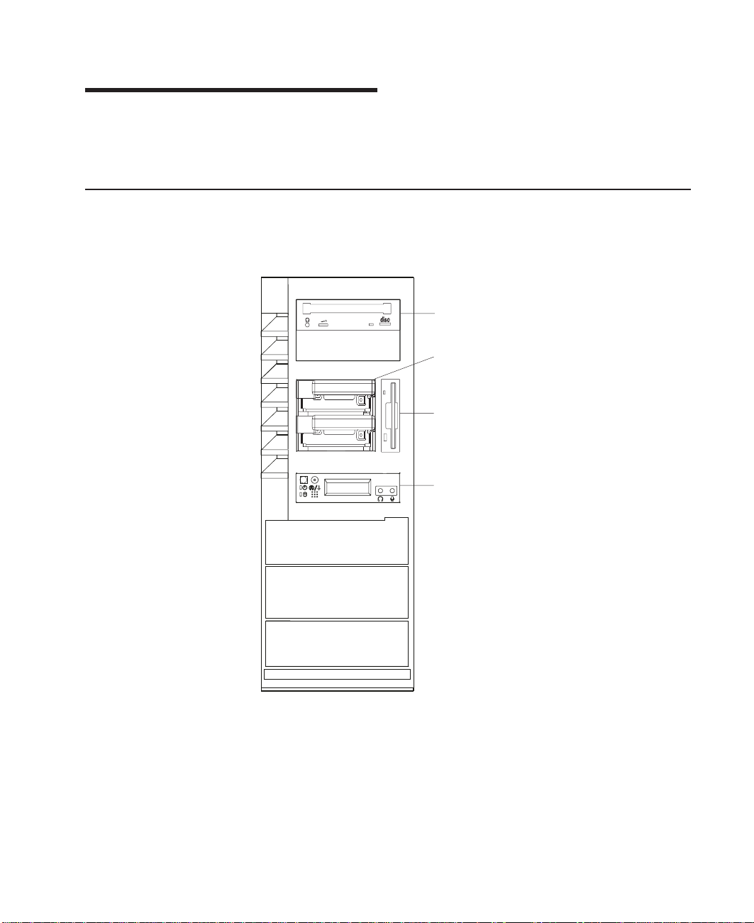
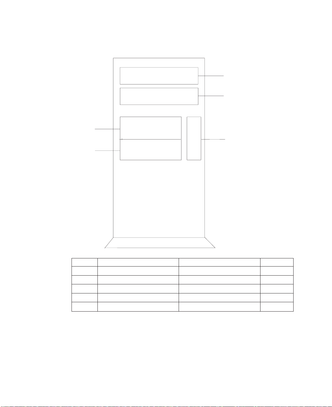
Front View with Media Door Removed
CD-ROM Drive
Disk Drives
Diskette Drive
Operator Panel
1
Page 20
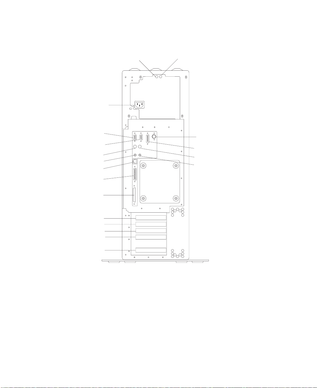
Rear View
14
13
15
10
12
16
4
5
8
17
18
1
3
2
7
6
9
11
2 Service Guide
19
Page 21

1 Power Supply LED
2 Power Supply Test Switch
3 Power Connector
4 Serial Connector S1
5 Serial Connector S2
6 AUI Ethernet Connector
7 Tablet Connector
8 Keyboard Connector
9 Mouse Connector
10 Audio Line Out
11 Audio Line In
12 RJ45 Ethernet Connector
13 Parallel Connector
14 External SCSI Connector
15 PCI Slot 5 (32-bit)
16 PCI Slot 4 (32-bit)
17 PCI Slot 3 (32-bit)
18 PCI Slot 2 (64-bit)
19 PCI Slot 1 (64-bit)
Chapter 1. Reference Information
3
Page 22
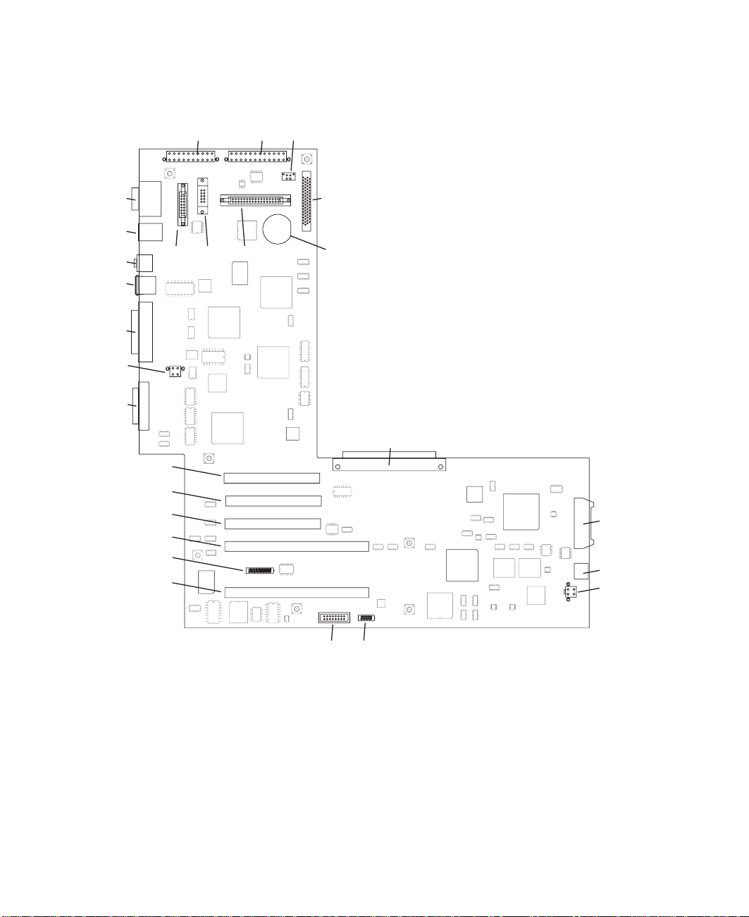
I/O Board Component Locations
J23
J24
J26
J25
J27
J21
J28
J12
J13
J14
J8
J15
J9
J20
J19
J18
J17
J16
J10
J7
J11
J4
J1
J2
J3
4 Service Guide
J6
J5
Page 23

J1 Operator panel power connector
J2 Operator panel audio connector
J3 I/O fan connector
J4 I/O board connector to system board
J5 VPD module connector
J6 ESP external connector
J7 Internal SCSI connector
J8, J9 64-bit PCI connectors
J10 CD-ROM audio connector
J11 Battery Socket
J12, J13, J14 32-bit PCI connectors
J15 Service processor external connector
J16 Power connector
J17 Diskette drive connector
J18 Tablet connector
J19 Power connector
J20 AUI Ethernet connector
J21 CEC fan connector
J23 Serial port connectors
J24 Keyboard/Mouse connector
J25 RJ45 Ethernet connector
J26 Audio in/out
J27 Parallel port connector
J28 External SCSI connector
Chapter 1. Reference Information
5
Page 24
SCSI IDs and Bay Locations
4
5
1
2
3
6 Service Guide
Index Bay Location Drive Name SCSI ID
1 Bay D2 CD-ROM SCSI ID 1
2 Bay D3 Media device SCSI ID 0
3 Bay D1 Diskette drive Non-SCSI
4 Bay D4 Disk drive SCSI ID 9
5 Bay D5 Disk drive SCSI ID 8
Note: The SCSI bus IDs listed are the recommended values. The SCSI IDs shown for
media devices indicate how the devics are set when shipped from the factory.
Field installations might not comply with these recommendations.
Page 25
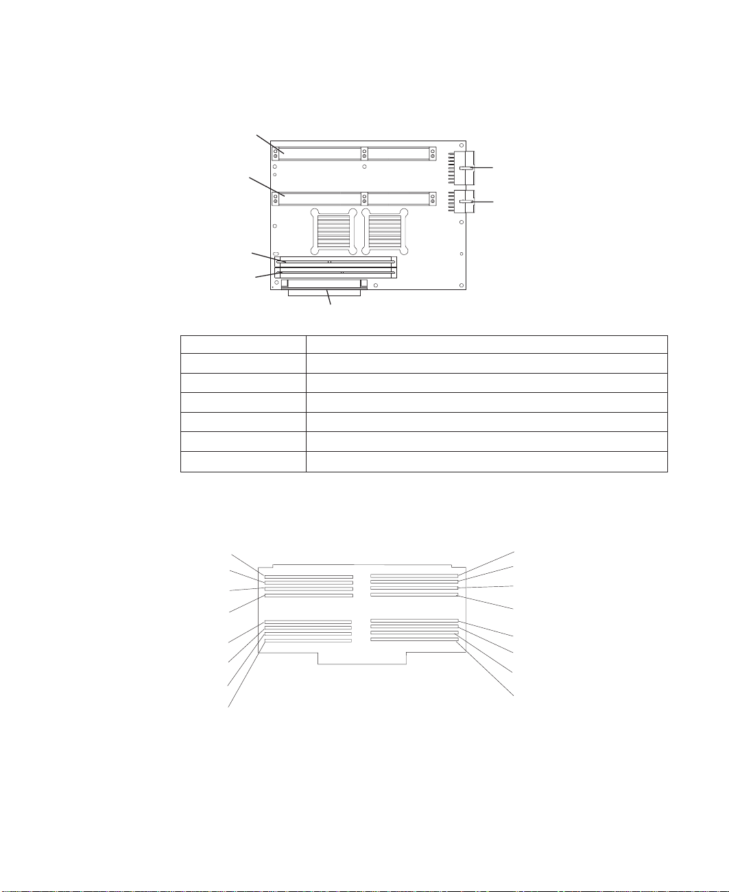
System Board Locations
J8
J6
J3
J2
J1 System board connector to I/O board
J2 Memory card 2 connector
J3 Memory card 1 connector
J5 Power supply connector
J6 Processor card connector #1 (Primary)
J7 Power supply connector
J8 Processor card connector #2
Memory Card Locations
Slot J15
Slot J13
Slot J11
Slot J9
Slot J7
Slot J5
Slot J3
Slot J1
J7
J5
J1
Slot J16
Slot J14
Slot J12
Slot J10
Slot J8
Slot J6
Slot J4
Slot J2
Note: Memory modules must be installed in pairs and in the correct slot configuration.
(Slots J1 and J2, J3 and J4, J5 and J6, and so on.)
Chapter 1. Reference Information 7
Page 26
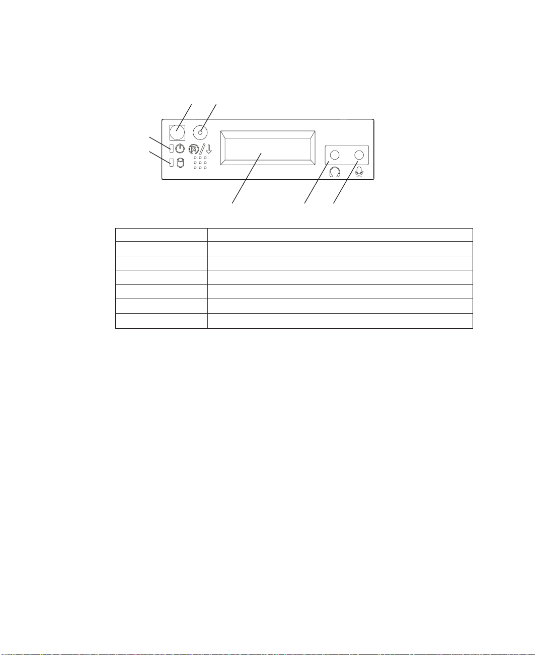
Operator Panel
1
2
3
4
5
1 Power-On Switch
2 Reset Switch
3 Power-On LED
4 Disk Drive Activity LED
5 Display
6 Headset Receptacle
7 Microphone Receptacle
6
7
8 Service Guide
Page 27
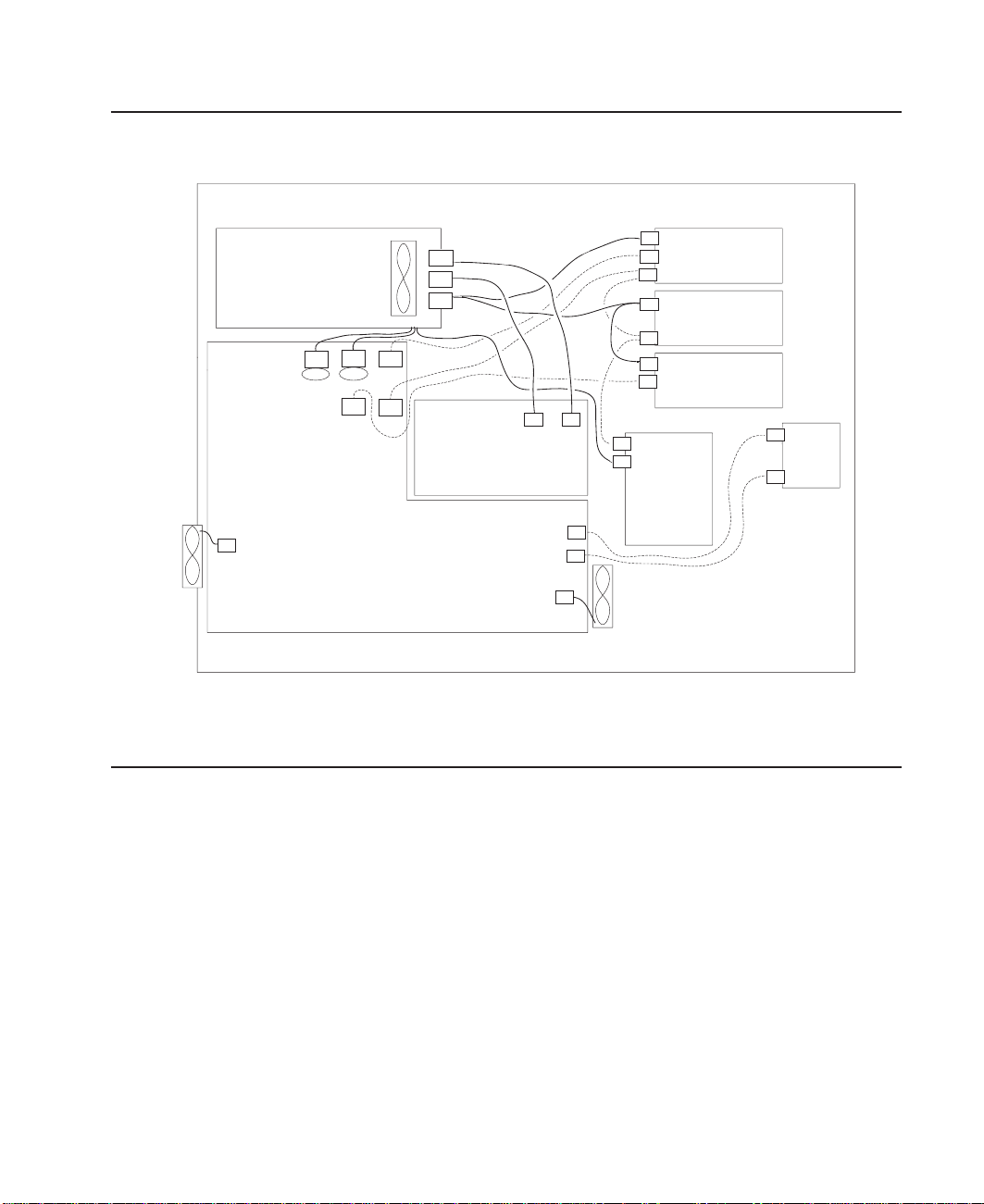
System Cables
Fan
SCSI
P6
Disk
Disk
Drives
Drives
Backplane
Fan
Power
Audio
SCSI
Power
SCSI
Power
Data
ROM
CD ROMCD
Media
Media
Device
Device
Diskette
Power
Operator
Operator
Panel
Panel
Audio
Power SupplyPower
J21
Supply
P3
J19
P4
J16
J17
Fan
J10
J7
P1
P2
P5
System BoardSystem Board
J7
J5
J1
J2
J3
I/O BoardI/O Board
Note: P3 cable goes into designated socket J19. P4 cable goes into designated socket
J16.
Location Codes
This system unit uses physical location codes in conjunction with AIX location codes to
provide mapping of the failing field replaceable units. The location codes are produced
by the system unit’s firmware and AIX.
Physical Location Codes
Physical location codes provide a mapping of logical functions in a platform (or
expansion sites for logical functions, such as connectors or ports) to their specific
locations within the physical structure of the platform.
Location Code Format
The location code is an alphanumeric string of variable length, consisting of a series of
location identifiers, separated by a dash (-), slash (/), or a pound sign (#) character. The
series is hierarchical; that is, each location identifier in the string is a physical or logical
child of the one preceding it.
Chapter 1. Reference Information 9
Page 28

v The - (dash) separator character represents a normal structural relationship where
the child is a separate physical package and it plugs into (or is connected to) the
parent. For example, P1-C1 is a processor card (C1) plugged into a planar (P1), or
P1-M1 is a memory card (M1) plugged into a planar (P1).
v The / (slash) separator character separates the base location code of a function from
any extended location information. A group of logical devices can have the same
base location code because they are all on the same physical package, but may
require extended location information to describe the connectors they support. For
example, P2/S1 describes the location of the serial port 1 controller and its connector
(S1), which is located on planar P2 (its base location code), but the / indicates that
further devices can be connected to it at the external S1 serial connector. The
keyboard controller and its connector likewise have location code P2/K1, which
means they have the same base location code (P2) as serial port 1, but a different
external connector. In contrast, the location code P2-K1 actually points to the device
connected to connector K1; that is, the keyboard. The location code P2/Z1 indicates
an integrated SCSI controller which drives connector Z1, while location codes of
P2-Z1-... point to the actual SCSI bus and devices.
v The # (pound sign) separator character indicates a cable connection between a
connector and parent.
The following are examples:
v P1-C1 identifies processor card C1 plugged into planar P1.
v P1-M1 identifies memory card M1 plugged into planar P1.
v P2/S1 identifies serial port 1 controller on I/O board P2, or the connector for serial
port 1.
v P1-K1 identifies a keyboard attached to connector K1 on planar P1.
v P2/Z1 identifies an integrated SCSI controller on planar P2 which drives connector
Z1.
v P2-Z1-... points to the actual SCSI bus and devices attached to Z1.
The . (period) identifies sub locations (DIMMs on a memory card, or SCSI addresses).
The following are examples:
v P1-M1.4 identifies memory DIMM 4 on memory card 1 plugged into planar P1.
v P1-C1.1 identifies processor 1 on processor card 1 plugged into planar P1.
v P2-Z1-A3.1 identifies a SCSI device with SCSI address of LUN 1 at SCSI ID 3
attached to SCSI bus 1, which is integrated on planar P2.
v P2.1 identifies a riser card plugged into planar P2.
AIX Location Codes
The basic formats of the AIX location codes are as follows:
v For non-SCSI devices/drives:
– AB-CD-EF-GH
v For SCSI devices/drives:
– AB-CD-EF-G,H
10 Service Guide
Page 29

For planars, cards, and non-SCSI devices, the location code is defined as follows:
AB-CD-EF-GH
||||
| | | Device/FRU/Port ID
| | Connector ID
| devfunc Number, Adapter Number or Physical Location
Bus Type or PCI Parent Bus
v The AB value identifies a bus type or PCI parent bus as assigned by the firmware.
v The CD value identifies adapter number, the adapter’s devfunc number, or physical
location. The devfunc number is defined as the PCI device number times 8, plus the
function number.
v The EF value identifies a connector.
v The GH value identifies a port, address, device, or FRU.
Adapters and cards are identified only with AB-CD.
The possible values for AB are:
00 Processor bus
01 ISA bus
02 EISA bus
03 MCA bus
04 PCI bus used in the case where the PCI bus cannot be identified
05 PCMCIA buses
xy For PCI adapters where x is equal to or greater than 1. The x and y are characters in the
range of 0-9, A-H, J-N, P-Z (O, I, and lower case are omitted) and are equal to the parent
bus’s ″ibm, aix-location″ open firmware property.
The possible values for CD depend on the adapter/card:
v For pluggable PCI adapters/cards, CD is the device’s devfunc number (PCI device
number times 8, plus the function number). The C and D are characters in the range
of 0-9, and A-F (hex numbers). Location codes therefore uniquely identify multiple
adapters on individual PCI cards.
v For pluggable ISA adapters, CD is equal to the order of the ISA cards
defined/configured either by SMIT or the ISAAdapter Configuration Service Aid.
v For integrated ISA adapters, CD is equal to a unique code identifying the ISA
adapter. In most cases, this code is equal to the adapter’s physical location code. In
cases where a physical location code is not available, CD will be FF.
EF is the connector ID, used to identify the adapter’s connector to which a resource is
attached.
GH is used to identify a port, device, or FRU. For example:
v For async devices, GH defines the port on the fanout box. The values are 00 to 15.
v For a diskette drive, H identifies either diskette drive 1 or 2. G is always 0.
v For all other devices, GH is equal to 00.
Chapter 1. Reference Information 11
Page 30

For integrated adapters, EF-GH is the same as the definition for a pluggable adapter.
For example, the location code for a diskette drive is 01-D1-00-00. A second diskette
drive is 01-D1-00-01.
For SCSI devices, the location code is defined as follows:
AB-CD-EF-G,H
| | |||
| | | | Logical Unit address of the SCSI Device
| | | Control Unit Address of the SCSI Device
| | Connector ID
| devfunc Number, Adapter Number or Physical Location
Bus Type or PCI Parent Bus
Where
AB-CD-EF are the same as non-SCSI devices.
G defines the control unit address of the device. Values of 0 to 15 are valid.
H defines the logical unit address of the device. Values of 0 to 255 are valid.
A bus location code that is also generated as ’00-XXXXXXXX’ where XXXXXXXX is
equivalent to the node’s unit address.
Examples of physical location codes displayed by AIX are as follows:
v First processor card plugged into planar 1:
P1-C1
v Second memory card in planar P1:
P1-M2
v Memory DIMM 12 on second memory card plugged into planar P1:
P1-M2.12
12 Service Guide
Examples of AIX location codes displayed are as follows:
v Integrated PCI adapter as follows:
10-80 Ethernet
10-60 Integrated SCSI Port 1 (internal)
10-88 Integrated SCSI Port 2 (external)
v Pluggable PCI adapters as follows:
20-58 to 20-5F Any PCI card in slot 1
20-60 to 20-67 Any PCI card in slot 2
10-68 to 10-6F Any PCI card in slot 3
10-70 to 10-77 Any PCI card in slot 4
10-78 to 10-7F Any PCI card in slot 5
v Integrated ISA adapters as follows:
01-D1 Diskette adapter
01-R1 Parallel port adapter
01-S1 Serial port 1 adapter
Page 31

01-S2 Serial port 2 adapter
01-S3 Serial port 3 adapter
01-K1 Keyboard adapter
v Device attached to SCSI controller
10-60-00-4,0 Device attached to integrated SCSI controller 1:
AIX and Physical Location Code Reference Table
AIX
Location
Codes
10-80
01-S1
01-S2
01-K1-01
01-K1-00
01-Q1-00
01-Q2-00
10-80
01-R1
10-88
10-78 to 10-7F
or
1F-XX
10-70 to 10-77
or
1E-XX
10-68 to 10-6F
or
1D-XX
20-60 to 20-67
or
2C-XX
20-58 to 20-5F
or
2B-XX
Physical
Location
Codes
P2/E1
P2/S1
P2/S2
P2/O1
P2/K1
P2/Q1
P2/Q2
P2/E1
P2/R1
P2/F1
P2/Z2
P2-I5
P2-I4
P2-I3
P2-I2
P2-I1
AUI Ethernet
Serial
Mouse
Keyboard
Tablet
Integrated Audio
RJ45 Ethernet
Parallel
CEC Fan
Ext SCSI
PCI 32-Bit
PCI 32-Bit
PCI 32-Bit
PCI 64-Bit
PCI 64-Bit
Chapter 1. Reference Information 13
Page 32

Physical
Location
Codes
AIX
Location
Codes
Internal SCSI
Diskette Drive
Processor Card
Processor Card
(primary)
Memory Card
Memory Card
Operator Panel
I/O Fan
P2/Z1
P2/D1
P1-C2
P1-C1
P1-M1
P1-M2
P2/L1
P2/F2
10-60
01-D1
14 Service Guide
Page 33

FRU Name AIX Location
System board 00-00 P1
Processor card 1 00-00 and 00–01
Processor card 2 00-02 and 00–03
Memory card 1 00-00 P1-M1 Memory card
Memory card 1
modules 1 thru 16
Memory card 2 00-00 P1-M2 Memory card
Memory card 2
modules 1 thru 16
I/O board 00-00 P2
Diskette Drive 01-D1-00-00 P2-D1 I/O board
Keyboard 01-K1-00-00 P2-K1 I/O board
Mouse 01-K1-01-00 P2-O1 I/O board
Diskette Port 01-D1 P2/D1 I/O board
Keyboard Port 01-K1-00 P2/K1 I/O board
Mouse Port 01-K1-01 P2/O1 I/O board
Tablet Port 01-Q1-01-00 P2/Q1 I/O board
Audio 01-Q2-00 P2/Q2 I/O board
Serial Port 1 01-S1 P2/S1 I/O board
Code
Central Electronics Complex (CEC)
(2–way card)
(2–way card)
00-00 P1-M1.1 through
00-00 P1-M2.1 through
Physical
Location Code
P1-C1 Processor
P1-C2 Processor
P1-M1.16
P1-M2.16
Integrated Devices
Physical
Connection
connector J6
connector J8
connector J3
Memory card
sockets J1, J2,
J3, J4, J5, J6, J7,
J8 J9, J10, J11,
J12, J13, J14,
J15, J16
connector J2
Memory card
sockets J1, J2,
J3, J4, J5, J6, J7,
J8 J9, J10, J11,
J12, J13, J14,
J15, J16
Connector J13
connector J24
connector J24
connector J17
connector J24
connector J24
connector J18
connector J26
connector J23
Logical
Identification
CPU ID proc0
and proc1 (2-way
card)
CPU ID proc2
and proc3 (2-way
card)
Extents: 8L, 8H,
10L, 10H, 12L,
12H, 14L, 14H,
9L, 9H, 11L, 11H,
13L, 13H, 15L,
15H
Extents: 8L, 8H,
10L, 10H, 12L,
12H, 14L, 14H,
9L, 9H, 11L, 11H,
13L, 13H, 15L,
5H
Base Address
0x0310
Base Address
0x0060
0x0060
0x03f0
0x0060
0x0060
0x0060
0x0060
0x0318
Chapter 1. Reference Information
15
Page 34

FRU Name AIX Location
Serial Port 2 01-S2 P2/S2 I/O board
Parallel Port 01-R1 P2/R1 I/O board
AUI Ethernet Port 10-80 P2/E1 I/O board
RJ45 Ethernet
Port
Internal SCSI Port 10-60 P2/Z1 I/O board
External SCSI
Port
Card in PCI Slot1P20-58 to 20-5F or
Card in PCI Slot2P20-60 to 20-67 or
Card in PCI Slot3P10-68 to 10-6F or
Card in PCI Slot4P10-70 to 10-77 or
Card in PCI Slot5P10-78 to 10-7F or
Base CD-ROM
(Bay D1)
Media Device in
Bay D2
DASD in Bay D4 10-60-00-9,0 P2-Z1-A9 Primary SCSI bus
DASD in Bay D5 10-60-00-8,0 P2-Z1-A8 Secondary SCSI
I/O fan F2 Fan connector J3
CEC fan F1 Fan connector
Code
10-80 P2/E1 I/O board
10-88 P2/Z2 I/O board
2B-xx
2C-xx
1D-xx
1E-xx
1F-xx
10-60-00-1, 0 P2-Z1-A1 Primary SCSI bus
10-60-00-0,0 P2-Z1-A0 Primary SCSI bus
Physical
Location Code
Pluggable Adapters
P2-I1 I/O board
P2-I2 I/O board
P2-I3 I/O board
P2-I4 I/O board
P2-I5 I/O board
SCSI Devices
Fans
Physical
Connection
connector J23
connector J27
connector J20
connector J25
connector J7
connector J28
connector J9
connector J8
connector J14
connector J13
connector J12
at system board
J21 at system
board
Logical
Identification
0x0218
0x0378
Host Bridge ID00,
Device 06
Host Bridge ID00,
Device 06
Host Bridge ID00,
Device 02
Host Bridge ID00,
Device 07
Host Bridge ID01,
Device 01
Host Bridge ID01,
Device 02
Host Bridge ID00,
Device 03
Host Bridge ID00,
Device 04
Host Bridge ID00,
Device 05
ID 1 (refer to the
note at the end of
this table)
ID 0 (refer to the
note at the end of
this table)
ID 9
bus ID 8
16 Service Guide
Page 35

FRU Name AIX Location
Code
I/O fan connector P2/F2 Fan connector J3
CEC fan
connector
Operator panel L1 I/O board
Operator panel
Connector
Power supply V1
Battery V2 I/O board
Notes:
1. The physical location code for the PCI slots, when empty, uses the P1/Ix notation, where the
’/’ identifies an integrated device (in this case the empty slot). A PCI device plugged into the
slot uses the P1-Ix notation, where the ’-’ identifies a plugged device.
2. The SCSI bus IDs are the recommended values. The SCSI IDs shown for media devices
indicate how the devices are set when they are shipped from the factory. Field installations
may not comply with these recommendations.
Physical
Location Code
P2/F1 Fan connector
Operator Panel
P2/L1 I/O board
Power Supply
Battery
Physical
Connection
at system board
J21 at system
board
connector J1
connector J1
connector J11
Logical
Identification
Specifications
Dimensions
The mechanical packaging, cooling, power supply, and environmental requirements for
the server are as follows:
v With pedestal:
– Height - 615 mm (24.2 inches)
– Depth - 681 mm (26.8 inches)
– Width - 340 mm (13.4 inches)
v Without pedestal:
– Height - 610 mm (24.0 inches)
– Depth - 681 mm (26.8 inches)
– Width - 221 mm (8.7 inches)
Chapter 1. Reference Information 17
Page 36

Weight
Configuration-dependent
Operating Environment - Class B
v Temperature - 16° to 32°C (60° to 90°F)
v Humidity - 8% to 80% noncondensing
v Maximum Altitude - 2135 m (7000 feet)
Power Source Loading
v Typical EMC Configuration - 0.3 kVA
v Maximum - 0.5 kVA
Power Requirements
v Typical - 275 watts
v Maximum - 640 watts
Power Factor
0.89 - 0.98
Operating Voltage
v 100 to 127V ac; 50 to 60 Hz
v 200 to 240V ac; 50 to 60 Hz
Heat Output (Maximum)
v Typical - 400 Btu/hr
v Maximum - 794 Btu/hr
Acoustics
v 6.0 Bels operating
v 5.5 Bels idle
18 Service Guide
Page 37

Power Cables
To avoid electrical shock, a power cable with a grounded attachment plug is provided.
Use only properly grounded outlets.
Power cables used in the United States and Canada are listed by Underwriter’s
Laboratories (UL) and certified by the Canadian Standards Association (CSA). These
power cords consist of the following:
v Electrical cables, Type SVT or SJT.
v Attachment plugs complying with National Electrical Manufacturers Association
(NEMA) 5-15P, that is:
″For 115 V operation, use a UL listed cable set consisting of a minimum 18 AWG,
Type SVT or SJT three-conductor cord a maximum of 15 feet in length and a parallel
blade, grounding type attachment plug rated at 15 A, 125 V.″
″For 230 V operation in the United States use a UL listed cable set consisting of a
minimum 18 AWG, Type SVT or SJT three-conductor cable a maximum of 15 feet in
length, and a tandem blade, grounding type attachment plug rated at 15 A, 250 V.″
v Appliance couplers complying with International Electrotechnical Commission (IEC)
Standard 320, Sheet C13.
Power cables used in other countries consist of the following:
v Electrical cables, Type HD21.
v Attachment plugs approved by the appropriate testing organization for the specific
countries where they are used.
″For units set at 230 V (outside of U.S.): use a cable set consisting of a minimum 18
AWG cable and grounding type attachment plug rated 15 A, 250 V. The cable set
should have the appropriate safety approvals for the country in which the equipment
will be installed and should be marked ′HAR’.″
Refer to “Chapter 10. Parts Information” on page 277 to find the power cables that are
available.
Chapter 1. Reference Information 19
Page 38

Service Inspection Guide
Perform a service inspection on the system when:
v The system is inspected for a maintenance agreement.
v Service is requested and service has not recently been performed.
v An alterations and attachments review is performed.
v Changes have been made to the equipment that may affect the safe operation of the
equipment.
v External devices with their own power cables have those cables attached.
If the inspection indicates an unacceptable safety condition, the condition must be
corrected before anyone can service the machine.
Note: The correction of any unsafe condition is the responsibility of the owner of the
system.
Perform the following checks:
1. Check the covers for sharp edges and for damage or alterations that expose the
internal parts of the system unit.
2. Check the covers for proper fit to the system unit. They should be in place and
secure.
3. Gently rock the system unit from side to side to determine if it is steady.
4. Set the power switch of the system unit to Off.
5. Remove the covers.
6. Check for alterations or attachments. If there are any, check for obvious safety
hazards such as broken wires, sharp edges, or broken insulation.
7. Check the internal cables for damage.
8. Check for dirt, water, and any other contamination within the system unit.
9. Check the voltage label on the back of the system unit to ensure that it matches
the voltage at the outlet.
10. Check the external power cable for damage.
11. With the external power cable connected to the system unit, check for 0.1 ohm or
less resistance between the ground lug on the external power cable plug and the
metal frame.
12. Perform the following checks on each device that has its own power cables:
a. Check for damage to the power cord.
b. Check for the correct grounded power cable.
c. With the external power cable connected to the device, check for 0.1 ohm or
less resistance between the ground lug on the external power cable the metal
frame of the device.
13. Install the covers.
20 Service Guide
Page 39

Chapter 2. Diagnostics Overview
Model 270 systems use an integrated set of software diagnostic procedures to facilitate
isolation of failing components and system maintenance. This book, along with the
RS/6000 and
the basis of the diagnostic procedures for the system. In particular, the following
sections in this book are important for the trained service representative to understand
and use when isolating a failure on the system:
v “Chapter 4. Checkpoints” on page 71
v “Chapter 5. Error Code to FRU Index” on page 93
v “Chapter 6. Loading the System Diagnostics” on page 147
v “Chapter 10. Parts Information” on page 277
The manufacturer recommends that systems configured with 4 GB of memory or
greater have access toa4mmor8mmtape drive for submission of system dump
information if required. This function can be accomplished through locally-attached or
network-attached devices, as appropriate.
Maintenance Analysis Procedures (MAPs)
Maintenance analysis procedures (MAPs) guide the trained service person through the
system. These MAPs are the entry point for all isolation and error-recovery procedures.
The MAPs are consistent with existing procedures and methods. The system uses a set
of integrated procedures, mentioned earlier, to which the MAPS are the primary entry
point.
Eserver
pSeries Diagnostics Information for Multiple Bus Systems
, are
The MAPS are as follows:
v Entry MAP
v Quick Entry MAP
v Problem Determination MAP
v Power MAP
v Minimum Configuration MAP
The Entry Map is the starting point for problem determination. The purpose of this MAP
is to quickly point to the appropriate MAP or service reference information either in this
book, or in the common book set, which includes the
Diagnostics Information for Multiple Bus Systems
Reference
The Quick Entry MAP is a subset of the Entry MAP and helps to save time for some
types of problems.
The Problem Determination MAP provides a structured analysis method to get an error
code if one is not provided by the customer, or if diagnostics cannot be loaded.
.
RS/6000 and
and the
Eserver
pSeries
PCI Adapter Placement
21
Page 40

Checkpoints
The Power MAP deals with isolation of components to diagnose a power problem. The
nature of power problems can be related to powering up and down the system, or
power failures that occur after power is turned on.
The Minimum Configuration MAP is used to locate defective components not found by
normal diagnostics or error-isolation methods. This MAP provides a systematic method
of isolation to the failing item or items.
Model 270 servers use various types of checkpoints, error codes, and SRNs, which are
referred to throughout this book (primarily in “Chapter 4. Checkpoints” on page 71,
“Chapter 5. Error Code to FRU Index” on page 93, “Chapter 6. Loading the System
Diagnostics” on page 147, and “Chapter 10. Parts Information” on page 277). These
codes may appear in the service processor boot progress log, the AIX error log, and the
operator panel display. Understanding the definition and relationships of these codes is
important to the service personnel who are installing or maintaining Model 270 servers.
Codes that can appear on the operator panel or in error logs are as follows:
Checkpoints
Checkpoints display in the operator panel from the time ac power is connected
to the system until the AIX login prompt is displayed after a successful
operating system boot. These checkpoints have the following forms:
E000 - E075
These checkpoints display from the time ac power is connected to the
system until the OK prompt displays on the operator panel display.
During this time, the service processor performs self-test and NVRAM
initialization.
E0A0 - E0E1
When power up is initiated, the service processor starts built-in
self-test (BIST) on the central electronics complex (CEC). VPD data
are read.
E0E2 - E2xx
This range indicates that the system processor is in control and is
initializing system resources.
E3xx These codes indicate that the system processor is running memory
tests.
E1xx The system firmware attempts to boot from devices in the boot list.
Control is passed to AIX when E105 (normal mode boot) or E15B
(service mode boot) displays on the operator panel display.
0xxx 0xxx codes are AIX checkpoints and configuration codes. Location
codes may also be shown on the operator panel display during this
time.
22 Service Guide
Page 41

FRU Isolation
Error Codes
If a fault is detected, an 8-digit error code is displayed in the operator panel
display.A location may be displayed at the same time on the second line of
the display.
Checkpoints can become error codes if the system fails to advance past the
point at which the code was presented.
For a list of checkpoints, see “Chapter 4. Checkpoints” on page 71. Each entry
provides a description of the event and the recommended action if the system
fails to advance.
SRNs Service request numbers, in the form xxx-xxx, may also be displayed on the
operator panel display and be noted in the AIX error log.
SRNs are listed in the
for Multiple Bus Systems
For a list of error codes and recommended actions for each code, see “Chapter 5. Error
Code to FRU Index” on page 93. These actions can refer to “Chapter 10. Parts
Information” on page 277, “Chapter 3. Maintenance Analysis Procedures (MAPs)” on
page 27, or provide informational message and directions. If a replacement part is
indicated, the part name is included. The respective AIX and physical location codes
are listed for each occurrence as required. For a list of location codes, see “AIX and
Physical Location Code Reference Table” on page 13.
RS/6000 and
.
Eserver
pSeries Diagnostics Information
To look up part numbers and view component diagrams, see “Chapter 10. Parts
Information” on page 277. The beginning of the chapter provides a parts index with the
predominant field replaceable units (FRUs) listed by name. The remainder of the
chapter provides illustrations of the various assemblies and components that make up
RS/6000 44P Series Model 270 systems.
Electronic Service Agent for the RS/6000
Service support for the system can be enhanced through the use of the application
program, Electronic Service Agent. This application provides a number of advantages
for the RS/6000 44P Series Model 270 customer, including automatic error reporting
and analysis without customer intervention. The Electronic Service Agent kit is provided
with the RS/6000 44P Series Model 270 server and includes the following:
v Electronic Service Agent for the RS/6000 program on CD-ROM
v The
CE Information Guide
For more details on Electronic Service Agent for the RS/6000, see the
,
Guide
for Electronic Service Agent
CE Information
Chapter 2. Diagnostics Overview 23
Page 42

Using the Service Processor and Electronic Service Agent Features
The service processor and Electronic Service Agent features protect users against
unnecessary system downtime by advising support personnel (both internal and
external) of any unexpected changes in the system environment. In combination, the
two features provide a flexible solution to automated system maintenance.
Service Processor
The service processor runs on its own power boundary and continually monitors
hardware attributes, the AIX operating system, and the environmental conditions within
the system. Any system failure which prevents the system from returning to an
operational state (a fully functional AIX operating system) is reported by the service
processor. The service processor is controlled by firmware and does not require the AIX
operating system to be operational to perform its tasks. If any system failures are
detected, the service processor has the ability to take predetermined corrective actions.
The methods of corrective actions are as follows:
v Surveillance
v Call home
v AIX operating system monitoring
Surveillance is a function in which the service processor monitors the system through
heartbeat
that the firmware can monitor. During system startup, the firmware surveillance monitor
is automatically enabled to check for heartbeats from the firmware. If a heartbeat is not
detected within a default period, the service processor cycles the system power and
attempts to restart until the system either restarts successfully, or a predetermined retry
threshold is reached. In the event the service processor is unsuccessful in bringing the
system online (or in the event that the user asked to be alerted to any service
processor-assisted restarts), the system can call home to report the error.
communication with the system firmware. The heartbeat is a periodic signal
24 Service Guide
The call home function can be initialized to call either a service center telephone
number, a customer administration center, or a digital pager telephone number. The
service processor can be configured to stop at the first successful call to any of the
numbers listed, or can be configured to call every number provided. If connected to the
service center, the service processor transmits the relevant system information (the
system’s serial number and model type) and service request number (SRN). If
connected to a digital pager service, the service processor inputs a customer voice
telephone number defined by the customer. An established sequence of digits or the
telephone number to a phone near the failed system could be used to signal a system
administrator to a potential system failure.
During normal operations, the service processor can also be configured to monitor the
AIX operating system. If AIX does not respond to the service processor heartbeat, the
service processor assumes the operating system is hung. The service processor can
automatically initiate a restart and, if enabled, initiate the call home function to alert the
appropriate people to the system hang. Enabling operating system surveillance also
enables AIX detect any service processor failures and report those failures to the
Electronic Service Agent application.
Page 43

Unlike the Electronic Service Agent, the service processor cannot be configured in a
client/server environment where one system can be used to manage all dial-out
functions for a set of systems.
Prior to installing the Electronic Service Agent feature, ensure that you have the latest
level of system firmware. You also need a properly configured modem. For more
information on configuring a modem, see “Appendix E. Modem Configurations” on
page 299.
Electronic Service Agent
The Electronic Service Agent is a software extension to the AIX operating system that
monitors the system while the AIX operating system is running. The Electronic Service
Agent monitors and analyzes all recoverable system failures, and, if needed, can
automatically place a service call to a service center (without user intervention).
The service center receives the machine type/serial number, host name, SRN, and a
problem description. The service center analyzes the problem report and, if warranted,
dispatches a service person to the customer site. The service center also determines if
any hardware components need to be ordered prior to the service person’s arrival.
The Electronic Service Agent code also gives the user the option to establish a single
system as the problem reporting server. A single system, accessible over the user
network, can be used as the central server for all the other systems on the local area
network (LAN) that are running the Electronic Service Agent application. If the
Electronic Service Agent application on a remote client decides a service request needs
to be placed, the client forwards the information to the Electronic Service Agent server
that dials the service center telephone number from its locally attached modem. In this
scenario, the user only needs to maintain a single analog line for providing call-out
capabilities for a large set of servers.
When used in a scalable parallel (SP) environment, a client/server type implementation
is configured. The Electronic Service Agent client code runs on each of the SP nodes.
The server component runs on the control workstation. In the event of any system
failures, the relevant information is transmitted to the control workstation through the
integrated Ethernet. After it has been alerted to the system failure, the control
workstation initiates actions to prepare and send the service request.
A modem is required for enabling automated problem reporting to the service center.
Configuration files for several types of modems are included as part of the Electronic
Service Agent package. Refer to “Appendix E. Modem Configurations” on page 299 for
more information on configuring your modem.
Chapter 2. Diagnostics Overview 25
Page 44

26 Service Guide
Page 45

Chapter 3. Maintenance Analysis Procedures (MAPs)
This chapter contains maintenance analysis procedures (MAPs).
Notes:
1. When possible, run online diagnostics in service mode. Online diagnostics perform
additional functions, compared to standalone diagnostics. This ensures that the
error state of the system is captured in NVRAM (non-volatile random access
memory) for your use in fixing the problem. The AIX error log and SMIT are only
available when diagnostics are run from the hard drive.
2. If more than eight digits are displayed in the operator panel, use only the first eight
digits to find the error in the tables. The digits that display beyond the first eight
digits are location codes that can assist you in diagnosing the problem. See
“Location Codes” on page 9.
3. Licensed programs frequently rely on network configuration and system information
stored on the VPD (vital product data) module on the operator panel control
assembly. If the MAPs indicate that the operator panel control assembly should be
replaced, swap the VPD module from the old operator panel to the new one. If the
existing VPD module must be replaced, call technical support for recovery
instructions. If recovery is not possible, notify the system owner that new keys for
licensed programs may be required.
4. If a network adapter or the I/O board is replaced, the network administrator must be
notified so that the client IP addresses used by the server can be changed. In
addition, the operating system configuration of the network controller might need to
be changed in order to enable system startup. Also check to ensure that any client
or server that addresses this system is updated.
Quick Entry MAP
Use the following table to determine your starting point.
If you replace FRUs or perform an action and the problem is still not corrected, go to
“MAP 1540: Minimum Configuration” on page 50 unless otherwise indicated in the
tables.
If you replace FRUs or perform an action and the problem is corrected, go to "MAP
410: Repair Checkout" in the
for Multiple Bus Systems
RS/6000 and
.
Eserver
pSeries Diagnostics Information
27
Page 46

Quick Entry MAP Table of Contents
Problem Description Page No.
Service Actions 28
System Stops With an 8-Digit Number Displayed 28
System Stops With a 4-Digit Number Displayed 28
System Stops With a 3-Digit Number Displayed 29
System Stops or Hangs With Alternating Numbers Displayed in the
Operator Display Panel.
Display Problem (Distortion, Blurring, Etc.) 29
Power and Cooling Problems 30
Flashing 888 in Operator Panel Display 30
Other Symptoms or Problems 30
You Cannot Find the Symptom in this Table 33
Symptom Action
You have parts to exchange or a corrective
action to perform.
You need to verify that a part exchange or
corrective action corrected the problem.
You need to verify correct system operation. Go to "MAP 410: Repair Checkout" in the
System Stops With A 8-Digit Number Displayed
The system stops with an 8-digit error code
displayed in the operator panel display or on
the console.
System Stops With A 4-Digit Number Displayed
Service Actions
1. Go to “Chapter 9. Removal and Replacement
Procedures” on page 223.
2. Go to "MAP 410: Repair Checkout" in the
RS/6000 and
Eserver
pSeries Diagnostics
Information for Multiple Bus Systems
Go to "MAP 410: Repair Checkout" in the
RS/6000 and
Eserver
pSeries Diagnostics
Information for Multiple Bus Systems
RS/6000 and
Eserver
pSeries Diagnostics
Information for Multiple Bus Systems
Record the error code. Go to “Chapter 5. Error
Code to FRU Index” on page 93.
29
.
.
.
28 Service Guide
Page 47

Symptom Action
The system stops and a 4-digit number is
displayed in the operator panel display or on
the console.
If the number displayed has the format ″E0xx″
then go to “Service Processor Checkpoints” on
page 71.
If the number displayed is in the range
″E1xx-EFFF″, make note of any location code
that is displayed on the second line of the
operator panel. If the location code indicates a
card slot (for example P2-I3), replace the card in
the indicated slot. If this does not correct the
problem, then go to “Firmware Checkpoints” on
page 75.
For all other numbers, record SRN 101-xxx,
where xxx is the last three digits of the four-digit
number displayed in the operator panel, then go
to the Fast Path MAP in the
Eserver
Multiple Bus Systems
Note: If the operator panel displays two sets of
numbers, use the bottom set of numbers as the
error code.
System Stops With A 3-Digit Number Displayed
The system stops and a 3-digit number
displayed in the operator panel display or on
the console.
Record SRN 101-xxx, where xxx is three-digit
number displayed in the operator panel, then go
to the Fast Path MAP in the
Eserver
Multiple Bus Systems
pSeries Diagnostics Information for
RS/6000 and
.
RS/6000 and
pSeries Diagnostics Information for
.
System Stops or Hangs With Alternating Numbers Displayed in the Operator Display Panel
The operator panel display alternates
between the code ″E1FD″ and another
″Exxx″ code.
The operator panel display alternates
between the codes ″E1DE″ and ″E1AD″.
Display Problem (Blank, Distortion, Blurring, Etc.).
Record both codes. Go to ″E1FD″ in “Firmware
Checkpoints” on page 75.
Record both codes. Go to ″E1DE″ in “Firmware
Checkpoints” on page 75.
Chapter 3. Maintenance Analysis Procedures
29
Page 48

Symptom Action
All display problems.
v If using a graphics display:
1. Go to the
procedures
2. If you do not find a problem, replace the
display adapter.
3. If you do not find a problem, suspect the
I/O board. Go to “MAP 1540: Minimum
Configuration” on page 50.
v Using an ASCII terminal:
1. Make sure that the ASCII terminal is
connected to S1.
2. If problems persist, go to the
problem determination
for the display.
determination procedures
3. If you do not find a problem, suspect the
I/O board. Go to “MAP 1540: Minimum
Configuration” on page 50.
Power and Cooling Problems
The power LEDs on the operator panel and
the power supply do not start flashing within
30 seconds of ac power application.
The power LEDs on the operator panel and
the power supply do not come on or stay on.
The power LEDs on the operator panel and
the power supply come on and stay on but
the system does not power on.
The cooling fan(s) do not come on or come
on but do not stay on.
Flashing 888 in Operator Panel Display
888 is displayed in the operator panel. Go to the Fast Path MAP in the
Go to “MAP 1520: Power” on page 45.
Go to “MAP 1520: Power” on page 45.
Go to “MAP 1520: Power” on page 45.
Go to “MAP 1520: Power” on page 45.
Eserver
Multiple Bus Systems
pSeries Diagnostics Information for
.
problem
for the terminal.
RS/6000 and
30 Service Guide
Other Symptoms or Problems
You have OK displayed. The service processor is ready. Go to ″MAP
You have STBY displayed. The service processor is ready. The system was
0020: Problem Determination Procedure″ in the
RS/6000 and
Information for Multiple Bus Systems
shut down by the operating system and is still
powered on. This condition can be requested by
a privileged system user with no faults. See
service processor error log for possible operating
system fault indications.
Eserver
pSeries Diagnostics
.
Page 49

Symptom Action
The system POST indicators are displayed on
the system console; the system pauses and
then restarts. The term ″POST indicators″
refers to the icons (graphic display) or device
mnemonics (ASCII terminal) that appear
during the power-on self-test (POST).
The system stops and POST indicators are
displayed on the system console. The term
″POST indicators″ refers to the icons (graphic
display) or device mnemonics (ASCII
terminal) that appear during the power-on
self-test (POST).
The system stops and the message
″STARTING SOFTWARE PLEASE WAIT...″ is
displayed on the ASCII terminal, or the boot
indicator
is displayed on a graphics terminal.
The system does not respond to the
password being entered, or the system login
prompt is displayed when booting in service
mode.
Go to “Boot Problems/Concerns” on page 90.
Go to “MAP 1540: Minimum Configuration” on
page 50 to isolate the problem.
Go to “Chapter 4. Checkpoints” on page 71.
Verify that the password is being entered from
the ASCII terminal or keyboard defined as the
system console. If so, then the keyboard or its
controller may be faulty.
v If entering the password from the keyboard
which is attached to the system, replace the
keyboard. If replacing the keyboard does not
fix the problem, replace the I/O board. (See
note 4 on page 27.)
v If entering the password from a keyboard
which is attached to an ASCII terminal, use the
problem determination procedures for the
ASCII terminal. Make sure the ASCII terminal
is connected to S1. Replace the I/O board if
these procedures do not reveal a problem.
v If the problem is fixed, go to "MAP 410: Repair
Checkout" in the
pSeries Diagnostics Information for Multiple
Bus Systems
“MAP 1540: Minimum Configuration” on
page 50 to isolate the problem.
RS/6000 and
. If the problem persists, go to
Eserver
Chapter 3. Maintenance Analysis Procedures
31
Page 50

Symptom Action
No codes are displayed on the operator panel
within a few seconds of turning on the
system. The operator panel is blank before
the system is powered on.
Reseat the operator panel cable. If the problem is
not resolved, replace these parts in the following
order:
1. Operator panel assembly. Update the VPD
information in the new operator panel.
2. I/O board (See notes 4 on page 27.)
If the problem is fixed, go to "MAP 410:
Repair Checkout" in the
Eserver
Multiple Bus Systems
go to “MAP 1540: Minimum Configuration” on
page 50 to isolate the problem.
The SMS configuration list or boot sequence
selection menu shows more SCSI devices
attached to a controller/adapter than are
actually attached.
A device may be set to use the same SCSI bus
ID as the control adapter. Note the ID being used
by the controller/adapter (this can be checked
and/or changed via an SMS utility), and verify
that no device attached to the controller is set to
use that ID.
If settings do not appear to be in conflict:
1. Replace the SCSI cable.
2. Replace the device.
3. Replace the SCSI adapter (or I/O board if
connected to one of the two integrated SCSI
controllers on the I/O board). (See note 4 on
page 27.
pSeries Diagnostics Information for
RS/6000 and
. If the problem persists,
32 Service Guide
Note: In a ″twin-tailed″ configuration where there
is more than one initiator device (normally
another system) attached to the SCSI bus, it may
be necessary to change the ID of the SCSI
controller or adapter with the System
Management Services.
Page 51

Symptom Action
The System Management Services menu is
displayed.
You have a problem that does not prevent the
system from booting.
You have an SRN. Go to the Fast Path MAP in the
You suspect a cable problem. See the
The device or media you are attempting to boot
from may be faulty.
1. Check the SMS error log for any errors. To
check the error log:
a. Choose error log from the utilities menu.
b. If an error is logged, check the time
stamp.
c. If the error was logged during the current
boot attempt, record it.
d. Look up the error in “Chapter 4.
Checkpoints” on page 71 and perform the
listed action.
e. If no recent error is logged in the error
log, continue to the next step below.
2. Try to boot from an alternate boot device
connected to the same controller as the
original boot device. If the boot succeeds,
replace the original boot device. (For
removable media devices try the media first.)
3. Go to “MAP 1540: Minimum Configuration” on
page 50.
Go to the Fast Path MAP in the
Eserver
Multiple Bus Systems
pSeries Diagnostics Information for
.
RS/6000 and
RS/6000 and
Eserver
Multiple Bus Systems
pSeries Diagnostics Information for
.
RS/6000 and
Eserver
pSeries
Adapters, Devices, and Cable Information for
Multiple Bus Systems
You do not have a symptom. Go to MAP 0020 in the
.
RS/6000 and
Eserver
pSeries Diagnostics Information for Multiple Bus
Systems
You have not determined a symptom. Go to “MAP 1020: Problem Determination” on
page 34.
You Cannot Find the Symptom in this Table
All other problems. Go to “MAP 1020: Problem Determination” on
page 34.
.
Chapter 3. Maintenance Analysis Procedures
33
Page 52

MAP 1020: Problem Determination
Purpose of This MAP
Use this MAP to get an error code if you were not provided one by the customer or you
are unable to load diagnostics. If you are able to load the diagnostics, go to MAP 0020
in the
RS/6000 and
The service processor may have recorded one or more symptoms in its error log. It is a
good idea to examine that error log before proceeding (see Service Processor System
Information Menu).
Be prepared to record code numbers and use those numbers in the course of analyzing
a problem. Go to “Step 1020-1” on page 35.
The service processor may have been set by the user to monitor server operations and
to attempt recoveries. You can disable these actions while you diagnose and service
the system. You can use that same service aid to restore the settings at the end of your
service action.
In case the service processor settings were not saved by the user, if you disable them,
make notes of their current settings so that you can restore them before you leave.
In addition to the parameters in the table below, you might want to disconnect the
modem to prevent incoming signals that could cause the system to power on.
Following are the service processor settings. The service processor menus are
described in “Service Processor Menus” on page 151.
Eserver
pSeries Diagnostics Information for Multiple Bus Systems
.
34 Service Guide
Surveillance From the Service Processor Setup Menu, go to
the Surveillance Setup Menu and disable
surveillance.
Unattended Start Mode From the Service Processor System Power
Control Menu, disable unattended start mode.
Reboot Policy From the System Power Control Menu, go to
the Reboot/Restart Policy Setup Menu and set:
1. Number of reboot attempts to 0 (zero)
2. Use OS-Defined restart policy to No
3. Enable supplemental restart policy to No.
Call Out From the Call-In/Call-Out Setup Menu, go to
the Serial Port Selection Menu and disable
call-out on both serial ports.
Page 53

Step 1020-1
The following steps analyze a failure to load the diagnostic programs.
Note: You are asked questions regarding the operator panel display. You are also
asked to perform certain actions based on displayed POST indicators.
1. Insert the diagnostic CD-ROM into the CD-ROM drive.
2. Turn off the power.
3. Turn on the power.
4. When the keyboard indicator is displayed (the word keyboard on an ASCII terminal
or the keyboard icon on a graphical display), press the F5 key on the directly
attached keyboard or the number 5 key on an ASCII terminal.
5. Enter a password, if you are requested.
6. Wait until the diagnostics are loaded or the system appears to stop.
7. Find your symptom in the following table. Then follow the instructions given in the
Action column.
Symptom Action
The diskette LED is blinking rapidly, or EIEA or
EIEB is displayed on the operator panel.
The system stops with a prompt to enter a
password.
The diagnostic operating instructions are
displayed.
The system login prompt is displayed. You may not have pressed the correct key or
The flash EPROM data is corrupted. Run the
recovery procedure for the flash EPROM. See
“Firmware Recovery” on page 207.
Enter the password. You are not allowed to
continue until a valid password has been
entered. When you have entered a valid
password, go to the beginning of this table and
wait for one of the other conditions to occur.
Go to MAP 0020 in the
pSeries Diagnostics Information for Multiple Bus
Systems
you may not have pressed the key soon
enough when you were to indicate a service
mode IPL of the diagnostic programs. If this
was the case, start over at the beginning of this
step.
Note: Perform the system shutdown procedure
before turning off the system.
.
RS/6000 and
Eserver
The system does not respond when the
password is entered.
If you are sure you pressed the correct key in a
timely manner, go to “Step 1020-2” on page 37.
Go to “Step 1020-2” on page 37.
Chapter 3. Maintenance Analysis Procedures
35
Page 54

Symptom Action
The system stopped and a POST indicator is
displayed on the system console and an 8-digit
error code is not displayed.
The system stops and a 4-digit number is
displayed in the operator panel display.
The System Management Services is
displayed.
All other symptoms. If you were directed here from the Entry MAP,
If the POST indicator represents:
v Memory, record error code M0MEM002.
v Keyboard, record error code M0KBD000.
v SCSI, record error code M0CON000.
v Network, record error code M0NET000.
v Speaker (audio), record error code
M0BT0000.
Go to “Step 1020-3” on page 38.
If the number displayed has the format ″E0xx″
then go to “Service Processor Checkpoints” on
page 71. If it is in the range ″E1xx-EFFF″ then
go to “Firmware Checkpoints” on page 75.
For all other numbers record SRN 101-xxx,
where xxx is the last three digits of the
four-digit number displayed in the operator
panel, then go to the Fast Path MAP in the
RS/6000 and
Information for Multiple Bus Systems
Note: If the operator panel displays two sets of
numbers, use the bottom set of numbers as the
error code.
Go to “Step 1020-4” on page 38.
go to “MAP 1540: Minimum Configuration” on
page 50. Otherwise, find the symptom in the
“Quick Entry MAP” on page 27.
Eserver
pSeries Diagnostics
.
36 Service Guide
Page 55

Step 1020-2
There is a problem with the keyboard.
Find the type of keyboard you are using in the following table. Then follow the
instructions given in the Action column.
Keyboard Type Action
Type 101 keyboard (U.S.). Identify by the size of
the Enter key. The Enter key is in only one
horizontal row of keys.
Type 102 keyboard World Trade (W.T.). Identify
by the size of the Enter key. The Enter key
extends into two horizontal rows.
Type 106 keyboard. (Identify by the Japanese
characters.)
ASCII terminal keyboard Go to the documentation for this type of
Record error code M0KBD001; then go to
“Step 1020-3” on page 38.
Record error code M0KBD002; then go to
“Step 1020-3” on page 38.
Record error code M0KBD003; then go to
“Step 1020-3” on page 38.
ASCII terminal and continue problem
determination.
Chapter 3. Maintenance Analysis Procedures
37
Page 56

Step 1020-3
Take the following actions:
1. Find the 8-digit error code in “Chapter 5. Error Code to FRU Index” on page 93.
Note: If the 8-digit error code is not listed in “Chapter 5. Error Code to FRU Index”
on page 93, look for it in the following:
v Any supplemental service manual for the device
v The diagnostic problem report screen
v The Service Hints service aid
v The CEREADME file (by using the Service Hints service aid).
Step 1020-4
Note: Service aids can be found in
RS/6000 and
Information for Multiple Bus Systems
2. Perform the action listed.
1. Turn off, then turn on the system unit.
2. When the keyboard indicator appears, press the F1 key on a directly attached
keyboard or the 1 key on an ASCII terminal.
3. When the System Management Services appear, check the error log for any errors.
v Display error log under utilities.
v If an error is logged, check the time stamp.
v If the error was logged during the current boot attempt, record it.
v Look up the error in the “Chapter 5. Error Code to FRU Index” on page 93 and
perform the listed action.
v If no recent error is logged in the error log, go to “MAP 1540: Minimum
Configuration” on page 50.
.
Eserver
pSeries Diagnostics
38 Service Guide
Page 57

MAP 1240: Memory Problem Resolution
Note: The firmware checkpoint that sent you here could be one of the following: E122,
E213, E214, E218, E220 or E3xx. These checkpoints are referred to as ″a
memory checkpoint″ in this MAP.
Purpose of This MAP
This MAP is used to troubleshoot a problem during the memory test when the system
stops at a memory checkpoint and no error code is displayed on the operator panel.
Notes:
1. If the symptom changes while you are using this MAP, check for loose cards,
cables, and obvious problems. If you do not find a problem, go to “MAP 1540:
Minimum Configuration” on page 50.
2. The service processor may have recorded one or more symptoms in its error log. It
is a good idea to examine that error log before proceeding (see Service Processor
System Information Menu).
3. The service processor may have been set by the user to monitor service operations
and to attempt recoveries. You might want to disable these actions while you
diagnose and service the system. If you disable them, make notes of their current
settings so that you can restore them before you leave. Following are the settings:
Surveillance From the Service Processor Setup Menu, go to
Unattended Start Mode From the Service Processor System Power
Reboot Policy From the System Power Control Menu, go to
Call Out From the Call-In/Call-Out Setup Menu, go to
General Memory Information
Be sure to unplug the power cable before removing or installing the memory card or
memory modules to avoid damage to them.
Memory cards can be installed in either slot (or both) on the system board. They can be
installed in any sequence.
the OS Surveillance Setup Menu and disable
surveillance.
Control Menu, disable unattended start mode.
the Reboot/Restart Policy Setup Menu and set:
1. Number of reboot attempts to 0 (zero)
2. Use OS-Defined restart policy to No
3. Enable supplemental restart policy to No.
the Serial Port Selection Menu and disable
call-out on both serial ports.
Chapter 3. Maintenance Analysis Procedures 39
Page 58

Step 1240-1
It is acceptable to have two partially populated memory cards in the system. The first
memory card does not have to be fully populated before memory on the second
memory card can be installed and used.
Memory modules, on the other hand, must be installed in matched (size and speed)
pairs. Refer to “Memory Modules” on page 239 for labeling of the memory card and
instructions on removing and installing modules. A single memory module pair can be
installed in module slots J1 and J2 (not slots J1 and J3). A second memory module pair
could be installed in module slots J5 and J6 (slots J3 and J4 do not have to be
populated first). In addition, memory module slots J1 and J2 need not be populated
before another slot pair.
1. Ensure that the diagnostics and the operating system are shut down.
2. Turn off the power.
3. Remove and reinstall any installed memory card(s).
4. Turn on the power.
Does the system stop with a memory checkpoint displayed on the operator
panel?
NO Reseating the memory card has corrected the problem.
Go to ″Map 0410: Repair Checkout″ in the
Diagnostics Information for Multiple Bus Systems
YES If there is only one memory card installed, tag it as ″suspect bad″ and go to
“Step 1240-7” on page 42.
If there are two memory card installed, go to “Step 1240-2”.
RS/6000 and
.
Eserver
pSeries
Step 1240-2
40 Service Guide
1. Turn off the power.
2. Remove the memory card from slot J3.
3. Turn on the power.
Does the system stop with a memory checkpoint displayed on the operator
panel?
NO Go to “Step 1240-4” on page 41.
YES Go to “Step 1240-3” on page 41.
Page 59

Step 1240-3
Step 1240-4
1. Turn off the power.
2. Remove the memory card from slot J2.
3. Install the memory card that was removed from slot J3 in its original location.
4. Turn on the power.
Does the system stop with a memory checkpoint displayed on the operator
panel?
NO Tag the memory card you removed from slot J2 as ″suspect bad″ and go to
“Step 1240-7” on page 42.
YES Go to “Step 1240-6” on page 42.
1. Turn off the power.
2. Remove the memory card from slot J2.
3. Install the memory module that was removed from slot J3 in its original location.
4. Turn on the power.
Does the system stop with a memory checkpoint displayed on the operator
panel?
NO Go to “Step 1240-5”.
YES Tag the memory module in slot J3 ″suspect bad″ and go to “Step 1240-7” on
page 42.
Step 1240-5
1. Turn off the power.
2. Install the memory card that was removed from slot J2 in its original location.
3. Turn on the power.
Does the system stop with a memory checkpoint displayed on the operator
panel?
NO Reseating the memory card has corrected the problem.
Go to ″Map 0410: Repair Checkout″ in the
Diagnostics Information for Multiple Bus Systems
YES Go to “Step 1240-6” on page 42.
Chapter 3. Maintenance Analysis Procedures 41
RS/6000 and
.
Eserver
pSeries
Page 60

Step 1240-6
Step 1240-7
One of the FRUs remaining in the system unit is defective.
1. Turn off the power.
2. Exchange the following FRUs in the order listed.
a. System board
b. Processor card(s)
3. Turn on the power.
Does the system stop with a memory checkpoint displayed on the operator
panel?
NO Go to ″Map 0410: Repair Checkout″ in the
Diagnostics Information for Multiple Bus Systems
YES Reinstall the original FRU.
Repeat this step until the defective FRU is identified or all the FRUs have been
exchanged.
If the symptom did not change and all the FRUs have been exchanged, go to
“MAP 1540: Minimum Configuration” on page 50.
1. Turn off the power.
2. Remove all installed memory modules from the memory card that you tagged as
″suspect bad.″ Record the positions of the memory modules as they are removed
so that when you are instructed to reinstall them, they can be installed in their
original positions.
3. Install one pair of memory modules.
4. Turn on the power.
RS/6000 and
.
Eserver
pSeries
42 Service Guide
Does the system stop with a memory checkpoint displayed on the operator
panel?
NO If there are no more memory modules to be installed, reseating the memory
modules on the memory card has corrected the problem.
If there was more than one pair of memory modules on the memory card, go
to “Step 1240-8” on page 43.
YES Go to “Step 1240-9” on page 43.
Page 61

Step 1240-8
Step 1240-9
1. Turn off the power.
2. Install one pair of memory modules.
3. Turn on the power.
Does the system stop with a memory checkpoint displayed on the operator
panel?
NO Repeat this step until all the memory modules are installed and tested.
If all the memory modules have been installed, reseating the memory modules
on the memory card has corrected the problem.
Go to ″Map 0410: Repair Checkout″ in the
Diagnostics Information for Multiple Bus Systems
YES Go to “Step 1240-9”.
The failure may be caused by the last pair of memory modules installed or the memory
card. To isolate the failing FRU, do the following:
1. Turn off the power.
2. Exchange the last memory module pair installed.
3. Turn on the power.
Does the system stop with a memory checkpoint displayed on the operator
panel?
NO Go to “Step 1240-11”on page 44.
YES Go to “Step 1240-10” on page 44.
RS/6000 and
.
Eserver
pSeries
Chapter 3. Maintenance Analysis Procedures 43
Page 62

Step 1240-10
Step 1240-11
One of the FRUs remaining in the system unit is defective.
1. Turn off the power.
2. Exchange the following FRUs in the order listed.
a. Memory card
b. System board
c. Processor card(s)
3. Turn on the power.
Does the system stop with a memory checkpoint displayed on the operator
panel?
NO Go to ″Map 0410: Repair Checkout″ in the
Diagnostics Information for Multiple Bus Systems
YES Reinstall the original FRU.
Repeat this step until the defective FRU is identified or all the FRUs have been
exchanged.
If the symptom did not change and all the FRUs have been exchanged, go to
“MAP 1540: Minimum Configuration” on page 50.
One or both of the memory modules that you exchanged in the previous step may be
defective. To isolate the failing memory module, do the following:
1. Turn off the power.
2. Reinstall one of the memory modules you exchanged in the previous step.
3. Turn on the power.
RS/6000 and
.
Eserver
pSeries
44 Service Guide
Does the system stop with a memory checkpoint displayed on the operator
panel?
NO Repeat this step with the second memory module you exchanged in the
previous step.
If both memory modules have been tested, go to ″Map 0410: Repair
Checkout″ in the
Multiple Bus Systems
YES Replace the memory module.
If you have not tested both memory modules, repeat this step with the second
memory module you exchanged in the previous step.
If the symptom did not change and both memory modules have been
exchanged, go to “Step 1240-10”.
RS/6000 and
.
Eserver
pSeries Diagnostics Information for
Page 63

MAP 1520: Power
Notes:
1. This is not a start-of-call MAP. Use this Power MAP only if you have been directed
2. The system unit has power LEDs located on the operator panel and the power
This procedure is used to locate power problems in system units. If a problem is
detected, this procedure helps you isolate the problem to a failing unit.
Observe the following safety notice during service procedures.
DANGER
An electrical outlet that is not correctly wired could place hazardous voltage
on metal parts of the system or the devices that attach to the system. It is the
responsibility of the customer to ensure that the outlet is correctly wired and
grounded to prevent an electrical shock.
Before installing or removing signal cables, ensure that the power cables for
the system unit and all attached devices are unplugged.
When adding or removing any additional devices to or from the system,
ensure that the power cables for those devices are unplugged before the
signal cables are connected. If possible, disconnect all power cables from the
existing system before you add a device.
here from a MAP step in the
Information for Multiple Bus Systems
supply. When the system is powered off, both LEDs should be blinking. When the
system is powered on, both LEDs should be on solid.
RS/6000 and
.
Eserver
pSeries Diagnostics
Use one hand, when possible, to connect or disconnect signal cables to
prevent a possible shock from touching two surfaces with different electrical
potentials.
During an electrical storm, do not connect cables for display stations, printers,
telephones, or station protectors for communication lines.
CAUTION:
This product is equipped with a three–wire power cable and plug for the user’s
safety. Use this power cable with a properly grounded electrical outlet to avoid
electrical shock.
DANGER
To prevent electrical shock hazard, disconnect the power cable from the
electrical outlet before relocating the system.
Chapter 3. Maintenance Analysis Procedures 45
Page 64

Step 1520-1
Step 1520-2
Step 1520-3
You might have been directed to this MAP for several reasons:
1. There is no indication of activity when the power-on switch on the operator panel is
pressed. None of the power LEDs light and none of the fans, including the fan in
the power supply, start to turn.
Go to “Step 1520-2”.
2. When the power-on switch on the operator panel is pressed, the system begins to
power on, but the operator panel power LED and/or the power supply LED does not
stay on.
Go to “Step 1520-5” on page 47.
1. Unplug the power cord from the system unit and the power outlet.
2. Check that the external power cord to the system unit has continuity.
3. Check that the power outlet has been wired correctly with the correct voltage.
4. Plug the power cord into the system unit and the power outlet.
Did you find a problem?
NO Go to “Step 1520-3”.
YES Correct the problem. Go to "MAP 410: Repair Checkout" in the
Eserver
1. Unplug the power cord from the system unit.
2. If you have not already done so, remove the covers as described in “Covers” on
page 226.
3. Press and hold the power-on switch on the operator panel for a few seconds to
discharge the power supply.
4. Unplug the power connectors (P1, P2, P3, P4, P5 and P6) from the power supply.
5. Plug the power cord into the system unit.
6. A small dark-colored switch is located on the back of the power supply, near the
back of the system. It is a normally off momentary switch. Press and hold this
switch for a few seconds while observing the fan in the power supply and the power
LED on the power supply.
pSeries Diagnostics Information for Multiple Bus Systems
RS/6000 and
.
46 Service Guide
Does the fan in the power supply turn on and the power LED on the power
supply change from blinking to solid while you hold the switch? (When you
release the switch, the system will power down.)
NO Replace the power supply. Go to ″Map 0410: Repair Checkout″ in the
and
Eserver
YES Go to “Step 1520-4” on page 47.
pSeries Diagnostics Information for Multiple Bus Systems
RS/6000
.
Page 65

Step 1520-4
Step 1520-5
The power supply is working normally.
1. Unplug the power cord from the system unit.
2. Press and hold the power-on switch on the operator panel for a few seconds to
discharge the power supply.
3. Plug the power connectors (P1, P2, P3, P4, P5 and P6) into the power supply.
4. Plug the power cord into the system unit.
If a cooling fan does not turn, the system will try to power up and then turn off when the
power-on switch on the operator panel is pressed (but not when the switch on the
power supply is pressed and held).
While holding the power supply switch do all the cooling fans turn?
NO Replace the faulty cooling fan. Go to "MAP 410: Repair Checkout" in the
RS/6000 and
Systems
YES Exchange the operator panel electronics assembly. Go to “Step 1520-5”.
Press the power-on switch on the operator panel to turn on the power.
Does the power LED on the operator panel come on and stay on?
NO Reinstall the original operator panel electronics assembly. Go to “Step 1520-6”.
YES Go to "MAP 410: Repair Checkout" in the
Diagnostics Information for Multiple Bus Systems
.
Eserver
pSeries Diagnostics Information for Multiple Bus
RS/6000 and
.
Eserver
pSeries
Step 1520-6
1. Unplug the power cord from the system unit.
2. Record the location of all the adapters. Label and record the location of any cables
attached to the adapters. Remove all the adapters.
3. Remove all the memory cards.
4. If two processor cards are installed, remove the lower one.
5. Unplug the power cable from the SCSI backplane.
6. Unplug the power cables from all the SCSI devices.
7. Unplug the front and rear cooling fan power connectors.
8. Plug the power cord into the system unit.
9. Press the power-on switch on the operator panel to turn on the power.
Does the power LED on the operator panel come on and stay on?
NO Go to “Step 1520-7” on page 48.
YES Go to “Step 1520-8” on page 49.
Chapter 3. Maintenance Analysis Procedures 47
Page 66

Step 1520-7
Either the processor card, system board, I/O board, or power supply is defective.
To test each FRU, exchange the FRUs that have not already been exchanged in the
following order:
1. Processor card
2. System board
3. I/O board
4. Power supply.
Press the power-on switch on the operator panel to turn on the power after each FRU
is exchanged. If the power stays on, the most recently-exchanged FRU was causing the
failure.
1. Unplug the power cord from the system unit.
2. Exchange one of the FRUs in the list.
3. Plug the power cord into the system unit.
4. Press the power-on switch on the operator panel to turn on the power.
Does the power LED on the operator panel come on and stay on?
NO Reinstall the original FRU.
Repeat this step until the defective FRU is identified or all the FRUs have been
exchanged.
If the symptom did not change and all the FRUs have been exchanged, call
service support for assistance.
If the symptom has changed, check for loose cards, cables, and obvious
problems. If you do not find a problem, return to “Step 1520-1” on page 46 in
this MAP and follow the instructions for the new symptom.
YES Go to "MAP 410: Repair Checkout" in the
Diagnostics Information for Multiple Bus Systems
RS/6000 and
.
Eserver
pSeries
48 Service Guide
Page 67

Step 1520-8
One of the parts that you removed or disconnected is probably defective. Install or
connect the parts one at a time in the following order to identify the failing part:
1. Processor card
2. Memory card(s)
3. Front cooling fan
4. Rear cooling fan
5. SCSI backplane power cable.
6. SCSI power cable(s), lowest bay to highest bay.
7. Adapter cards, lowest slot to highest slot.
Press the power-on switch on the operator panel to turn on the power after each part is
installed or connected. If the system does not power on or the power does not stay on,
the most recently installed or connected part is causing the failure.
1. Turn off the power.
2. Unplug the power cord from the system unit.
3. Install or connect one of the parts in the list.
4. Plug the power cord into the system unit.
5. Press the start/stop switch on the operator panel to turn on the power.
Does the power LED on the operator panel come on and stay on?
NO Replace the last part you installed.
Repeat these steps until all the parts have been installed or connected.
If the symptom did not change and all the parts have been installed or
connected, call your service support person for assistance.
If the symptom has changed, check for loose cards, cables, and obvious
problems. If you do not find a problem, return to “Step 1520-1” on page 46 in
this MAP and follow the instructions for the new symptom.
YES Go to "MAP 410: Repair Checkout" in the
Diagnostics Information for Multiple Bus Systems
RS/6000 and
.
Eserver
pSeries
Chapter 3. Maintenance Analysis Procedures 49
Page 68

MAP 1540: Minimum Configuration
Notes:
1. Be sure to unplug the power cable before removing or installing processor card(s),
memory card(s), system board or I/O board, to avoid damage to them.
2. This MAP assumes that a CD-ROM drive is installed and connected to the
integrated SCSI adapter, and a diagnostic CD-ROM is available.
3. If a power-on password or privileged-access password is installed, you are
prompted to enter the password before the diagnostic CD-ROM can load.
4. The term ″POST indicators″ refers to the icons (graphics display) or device
mnemonics (ASCII terminal) that appear during the power-on self-test (POST).
5. The service processor might have recorded one or more symptoms in its error log.
It is a good idea to examine that error log before proceeding (see Service Processor
System Information Menu).
6. The service processor might have been set by the user to monitor server operations
and to attempt recoveries. You might want to disable these actions while you
diagnose and service the system. If you disable them, make notes of their current
settings so that you can restore them before you leave. The following are the
settings:
Surveillance From the Service Processor Setup Menu, go to
Unattended Start Mode From the Service Processor System Power
Reboot Policy From the System Power Control Menu, go to
Call Out From the Call-In/Call-Out Setup Menu, go to
the Surveillance Setup Menu and disable
surveillance.
Control Menu, disable unattended start mode.
the Reboot/Restart Policy Setup Menu and set:
1. Number of reboot attempts to 0 (zero)
2. Use OS-Defined restart policy to No
3. Enable supplemental restart policy to No.
the Serial Port Selection Menu and disable
call-out on both serial ports.
50 Service Guide
Page 69

Purpose of this MAP
This MAP is used to locate defective FRUs not found by normal diagnostics. For this
procedure, diagnostics are run on a minimally configured system. If a failure is detected
on the minimally configured system, the remaining FRUs are exchanged one at a time
until the failing FRU is identified. If a failure is not detected, FRUs are added back until
the failure occurs. The failure is then isolated to the failing FRU.
Step 1540-1
1. Insert the diagnostic CD-ROM into the CD-ROM drive.
Note: If you cannot insert the diagnostic CD-ROM, go to “Step 1540-2” on page 52.
2. Ensure that the diagnostics and the operating system are shut down.
3. Turn off the power.
4. Turn on the power.
5. When the keyboard indicator is displayed (the word keyboard on an ASCII terminal
or the keyboard icon on a graphical display), press the F5 key on the directly
attached keyboard or the number 5 key on an ASCII terminal.
6. Enter the appropriate password if you are prompted to do so.
Is the ″Please define the System Console″ screen displayed?
NO Go to “Step 1540-2” on page 52.
YES Go to “Step 1540-18” on page 66.
Chapter 3. Maintenance Analysis Procedures 51
Page 70

Step 1540-2
1. Turn off the power.
2. If you have not already done so, configure the service processor with the
instructions in note 6 on page 50 and then return here and continue.
3. Exit service processor menus and remove the power cable.
4. Disconnect all external cables (parallel, serial port 1, serial port 2, keyboard,
mouse, tablet, Ethernet, SCSI) from the I/O planar.
5. Remove the side cover.
6. Record the slot numbers of the PCI adapters. Label and record the location of any
cables attached to the adapters. Disconnect any cables attached to the adapters
and remove all the adapters.
7. Remove the second processor card from slot J8 (if present). (If the second
processor card has been removed, ensure that the first processor card is
installed.).
8. Record the slot numbers of the memory modules. Remove all installed memory
modules except for one pair from the first memory card.
Note: Memory modules must be reinstalled in pairs and in the correct slots. For
example, install the first pair in slots J1 and J2.
9. Remove the second memory card from slot J2, if present.
10. Disconnect the SCSI cable from the SCSI connector (J7) on the I/O board.
11. Disconnect the signal and power connectors from the disk drive cage backplane.
12. Remove the disk drive(s) from the disk drive cage.
13. Disconnect the signal and power connectors from all the SCSI devices except the
CD-ROM drive.
14. Disconnect the diskette drive cable from the diskette drive connector (J17) on the
I/O board.
15. Plug in the power cable (and wait for OK on the operator panel display).
16. Turn on the power.
52 Service Guide
Does the system stop with code E1F2, E1F3, STBY or 4BA00830 displayed on the
operator panel?
NO Go to “Step 1540-3” on page 53.
YES If a second processor card was removed, go to “Step 1540-4” on page 54.
If the system has only one processor card, go to “Step 1540-5” on page 54.
Page 71

Step 1540-3
One of the FRUs remaining in the system unit is defective.
If a memory module is exchanged, ensure that the new module is the same size and
speed as the original module.
1. Turn off the power, remove the power cable, and exchange the FRUs in the
following order:
v Processor card
v Memory modules in odd numbered slots (J1, J3, J5, and so on.)
v Memory modules in even numbered slots (J2, J4, J6, and so on.)
v Memory card
v System board
v I/O board (see note 4 on page 27)
v Power supply.
2. Plug in the power cable (and wait for OK on the operator panel display).
3. Turn on the power.
Does the system stop with code E1F2, E1F3, STBY or 4BA00830 displayed on the
operator panel?
NO Reinstall the original FRU.
Repeat the FRU replacement steps until the defective FRU is identified or all
the FRUs have been exchanged.
If the symptom did not change and all the FRUs have been exchanged, call
service support for assistance.
If the symptom has changed, check for loose cards, cables, and obvious
problems. If you do not find a problem, return to “Step 1540-1” on page 51 in
this MAP and follow the instructions for the new symptom.
YES Go to "MAP 410: Repair Checkout" in the
Diagnostics Information for Multiple Bus Systems
RS/6000 and
.
Eserver
pSeries
Chapter 3. Maintenance Analysis Procedures 53
Page 72

Step 1540-4
No failure was detected with this configuration.
1. Turn off the power and remove the power cable.
2. Reinstall the second processor card.
3. Plug in the power cable (and wait for OK on the operator panel display).
4. Turn on the power.
Does the system stop with code E1F2, E1F3, STBY or 4BA00830 displayed on the
operator panel?
NO One of the FRUs remaining in the system unit is defective.
In the following order, exchange the FRUs that have not been exchanged:
1. Processor card (last one installed)
2. System board
3. I/O board (See note 4 on page 27.)
Repeat this step until the defective FRU is identified or all the FRUs have been
exchanged.
If the symptom did not change and all the FRUs have been exchanged, call
your service support person for assistance.
If the symptom changed, check for loose cards and obvious problems. If you
do not find a problem, return to “Step 1540-1” on page 51 and follow the
instructions for the new symptom.
YES Go to “Step 1540-5”.
Step 1540-5
54 Service Guide
No failure was detected with this configuration.
1. Turn off the power and remove the power cable.
2. Install a pair of memory modules.
3. Plug in the power cable (and wait for OK on the operator panel display).
4. Turn on the power.
Does the system stop with code E1F2, E1F3, STBY or 4BA00830 displayed on the
operator panel?
NO Go to “Step 1540-6” on page 55.
YES Repeat this step until all the memory modules are installed and tested.
After all the memory modules are installed and tested, record the positions of
the memory modules on the second memory card. Remove all of the memory
modules from the second memory card except one pair. Repeat this step with
the second memory card (if previously installed).
Go to “Step 1540-9” on page 57.
Page 73

Step 1540-6
Step 1540-7
The failure might be caused by the last pair of memory modules installed or the
memory card. To isolate the failing FRU, do the following:
1. Turn off the power and remove the power cable.
2. Exchange the last memory module pair installed.
3. Reinstall the power cable.
4. Turn on the power.
Does the system stop with code E1F2, E1F3, STBY or 4BA00830 displayed on the
operator panel?
NO Go to “Step 1540-8” on page 56.
YES Go to “Step 1540-7”.
One or both of the memory modules that you exchanged in the previous step might be
defective. To isolate the failing memory module, do the following:
1. Turn off the power and remove the power cable.
2. Reinstall one of the memory modules you installed in the previous step.
3. Plug in the power cable (and wait for OK on the operator panel display).
4. Turn on the power.
Does the system stop with code E1F2, E1F3, STBY or 4BA00830 displayed on the
operator panel?
NO Replace the memory module.
If you have not tested both memory modules, repeat this step with the second
memory module you exchanged in the previous step.
If the symptom did not change and both memory modules have been
exchanged, go to “Step 1540-8” on page 56.
YES Repeat this step with the second memory module you exchanged in the
previous step.
If both memory modules have been tested, go to "MAP 410: Repair Checkout"
in the
RS/6000 and
Systems
.
Eserver
pSeries Diagnostics Information for Multiple Bus
Chapter 3. Maintenance Analysis Procedures 55
Page 74

Step 1540-8
One of the FRUs remaining in the system unit is defective.
1. Turn off the power and remove the power cable.
2. Exchange the FRUs in the following order:
a. Memory card
b. System board
c. I/O board (see note 4 on page 27).
d. Power supply.
3. Plug in the power cable (and wait for OK on the operator panel display).
4. Turn on the power.
Does the system stop with code E1F2, E1F3, STBY or 4BA00830 displayed on the
operator panel?
NO Reinstall the original FRU.
Repeat this step until the defective FRU is identified or all the FRUs have been
exchanged.
If the symptom did not change and all the FRUs have been exchanged, call
service support for assistance.
If the symptom has changed, check for loose cards, cables, and obvious
problems. If you do not find a problem, return to “Step 1540-1” on page 51 in
this MAP, and follow the instructions for the new symptom.
YES Go to "MAP 410: Repair Checkout" in the
Diagnostics Information for Multiple Bus Systems
RS/6000 and
.
Eserver
pSeries
56 Service Guide
Page 75

Step 1540-9
1. Turn off the power.
2. Reconnect the system console.
Notes:
a. If an ASCII terminal has been defined as the system console, attach the ASCII
terminal cable to the S1 connector on the rear of the system unit.
b. If a display attached to a display adapter has been defined as the system
console, install the display adapter and connect the display to it. Plug the
keyboard into the keyboard connector on the rear of the system unit.
3. Turn on the power.
4. If the ASCII terminal or graphics display (including display adapter) is connected
differently than it was previously, the Console Selection screen appears and
requires that a new console be selected.
5. When the keyboard indicator is displayed, press the F1 key on the directly attached
keyboard or the number 1 key on an ASCII terminal to start the system
management services.
6. Enter the appropriate password if you are prompted to do so.
Is the SMS screen displayed?
NO One of the FRUs remaining in the system unit is defective.
In the following order, exchange the FRUs that have not been exchanged:
1. Go to the problem determination procedures (test procedures) for the
device attached to the S1 serial port or the display attached to the graphics
adapter, and test that device. If a problem is found, follow the procedures
for correcting the problem on that device.
2. Graphics adapter (if installed).
3. Cable (async or graphics).
4. I/O board (see note 4 on page 27.)
Repeat this step until the defective FRU is identified or all the FRUs have been
exchanged.
If the symptom did not change and all the FRUs have been exchanged, call
service support for assistance.
If the symptom changed, check for loose cards and obvious problems. If you
do not find a problem, return to “Step 1540-1” on page 51 and follow the
instructions for the new symptom.
YES Go to “Step 1540-10” on page 58.
Chapter 3. Maintenance Analysis Procedures 57
Page 76

Step 1540-10
1. Make sure the diagnostic CD-ROM is inserted into the CD-ROM drive.
2. Turn off the power and remove the power cable.
3. Plug the SCSI cable into the SCSI connector (J7) on the I/O board.
4. Plug in the power cable (and wait for OK on the operator panel display).
5. Turn on the power.
6. After the keyboard indicator is displayed, press the F5 key on the directly attached
keyboard or the number 5 key on an ASCII terminal keyboard.
7. Enter the appropriate password if you are prompted to do so.
Is the ″Please define the System Console″ screen displayed?
NO One of the FRUs remaining in the system unit is defective.
In the following order, exchange the FRUs that have not been exchanged:
1. SCSI cable
2. CD-ROM drive
3. I/O board (see note 4 on page 27)
4. Processor card
5. Power supply.
Repeat this step until the defective FRU is identified or all the FRUs have been
exchanged.
If the symptom did not change and all the FRUs have been exchanged, call
service support for assistance.
If the symptom has changed, check for loose cards, cables, and obvious
problems. If you do not find a problem, return to “Step 1540-1” on page 51 in
this MAP and follow the instructions for the new symptom.
YES Go to “Step 1540-11” on page 59.
58 Service Guide
Page 77

Step 1540-11
The system is working correctly with this configuration. One of the SCSI devices that
you disconnected might be defective.
1. Make sure the diagnostic CD-ROM is inserted into the CD-ROM drive.
2. Turn off the power and remove the power cable.
3. Connect the signal and power connectors to one of the SCSI devices (CD-ROM
drive, tape drive, disk drive, and so on.) Do not connect the signal and power
connectors to the backplane at this time.
4. Plug in the power cable (and wait for OK on the operator panel display).
5. Turn on the power.
6. After the keyboard indicator is displayed, press the F5 key on the directly attached
keyboard or the number 5 key on an ASCII terminal keyboard.
7. Enter the appropriate password if you are prompted to do so.
Is the ″Please define the System Console″ screen displayed?
NO One of the FRUs remaining in the system unit is defective.
In the following order, exchange the FRUs that have not been exchanged.
1. SCSI cable
2. Last SCSI device connected (CD-ROM drive, tape drive, and so on)
3. I/O board (see note 4 on page 27)
4. Processor card
5. Power supply.
Repeat this step until the defective FRU is identified or all the FRUs have been
exchanged.
If the symptom did not change and all the FRUs have been exchanged, call
service support for assistance.
If the symptom has changed, check for loose cards, cables, and obvious
problems. If you do not find a problem, return to “Step 1540-1” on page 51 in
this MAP and follow the instructions for the new symptom.
YES Repeat this step, adding one SCSI device at a time, until all the SCSI devices
that were attached to the integrated SCSI adapter, except the backplane, are
connected and tested.
Go to “Step 1540-12” on page 60.
Chapter 3. Maintenance Analysis Procedures 59
Page 78

Step 1540-12
The system is working correctly with this configuration. The backplane may be
defective.
1. Make sure the diagnostic CD-ROM is inserted into the CD-ROM drive.
2. Turn off the power and remove the power cable.
3. Connect the signal and power connectors to the backplane.
4. Plug in the power cable (and wait for OK on the operator panel display)
5. Turn on the power.
6. After the keyboard indicator is displayed, press the F5 key on the directly attached
keyboard or the number 5 key on an ASCII terminal keyboard.
7. Enter the appropriate password if you are prompted to do so.
Is the ″Please define the System Console″ screen displayed?
NO One of the FRUs remaining in the system unit is defective.
In the following order, exchange the FRUs that have not been exchanged.
1. SCSI cable
2. Disk drive cage backplane
Repeat this step until the defective FRU is identified or all the FRUs have been
exchanged.
If the symptom did not change and all the FRUs have been exchanged, call
service support for assistance.
If the symptom has changed, check for loose cards, cables, and obvious
problems. If you do not find a problem, return to “Step 1540-1” on page 51 in
this MAP and follow the instructions for the new symptom.
YES Go to “Step 1540-13” on page 61.
60 Service Guide
Page 79

Step 1540-13
The system is working correctly with this configuration. One of the disk drives that you
removed from the disk cage might be defective.
1. Make sure the diagnostic CD-ROM is inserted into the CD-ROM drive.
2. Turn off the power and remove the power cable.
3. Install a disk drive in the disk drive cage.
4. Plug in the power cable (and wait for OK on the operator panel display).
5. Turn on the power.
6. After the keyboard indicator is displayed, press the F5 key on the directly attached
keyboard or the number 5 key on an ASCII terminal keyboard.
7. Enter the appropriate password if you are prompted to do so.
Is the ″Please define the System Console″ screen displayed?
NO In the following order, exchange the FRUs that have not been exchanged.
1. Last disk drive installed
2. Disk drive cage backplane
Repeat this step until the defective FRU is identified or all the FRUs have been
exchanged.
If the symptom did not change and all the FRUs have been exchanged, call
service support for assistance.
If the symptom has changed, check for loose cards, cables, and obvious
problems. If you do not find a problem, return to “Step 1540-1” on page 51 in
this MAP, and follow the instructions for the new symptom.
YES Repeat this step with the second disk drive (if it was installed).
Go to “Step 1540-14” on page 62.
Chapter 3. Maintenance Analysis Procedures 61
Page 80

Step 1540-14
The system is working correctly with this configuration. The diskette drive might be
defective.
1. Make sure the diagnostic CD-ROM is inserted into the CD-ROM drive.
2. Turn off the power and remove the power cable.
3. Plug the diskette drive cable into the diskette drive connector (J17) on the I/O
board.
4. Plug in the power cable (and wait for OK on the operator panel display).
5. Turn on the power.
6. After the keyboard indicator is displayed, press the F5 key on the directly attached
keyboard or the number 5 key on an ASCII terminal keyboard.
7. Enter the appropriate password if you are prompted to do so.
Is the ″Please define the System Console″ screen displayed?
NO One of the FRUs remaining in the system is defective.
In the following order, exchange the FRUs that have not been exchanged.
1. Diskette drive
2. Diskette drive cable
3. I/O board (see note 4 on page 27)
4. Power supply
Repeat this step until the defective FRU is identified or all the FRUs have been
exchanged.
If the symptom did not change and all the FRUs have been exchanged, call
service support for assistance.
If the symptom has changed, check for loose cards, cables, and obvious
problems. If you do not find a problem, return to “Step 1540-1” on page 51 in
this MAP and follow the instructions for the new symptom.
YES Go to “Step 1540-15” on page 63.
62 Service Guide
Page 81

Step 1540-15
The system is working correctly with this configuration. One of the devices that you
disconnected from the I/O board may be defective.
1. Turn off the power and remove the power cable.
2. Attach an I/O board device cable (parallel, serial port 1, serial port 2, AUI/RJ45
Ethernet, Ultra-2 SCSI, tablet, keyboard or mouse) that had been removed.
3. Plug in the power cable (and wait for OK on the operator panel display).
4. Turn on the power.
5. If the Console Selection screen displays, choose the system console.
6. After the keyboard indicator is displayed, press the F5 key on the directly attached
keyboard or the number 5 key on an ASCII terminal keyboard.
7. Enter the appropriate password if you are prompted to do so.
Is the ″Please define the System Console″ screen displayed?
NO The last device or cable that you attached is defective.
To test each FRU, exchange the FRUs in the following order:
1. Device and cable (last one attached)
2. I/O board (see note 4 on page 27).
If the symptom did not change and all the FRUs have been exchanged, call
service support for assistance.
If the symptom has changed, check for loose cards, cables, and obvious
problems. If you do not find a problem, return to “Step 1540-1” on page 51 in
this MAP and follow the instructions for the new symptom.
Go to ″Map 0410: Repair Checkout″ in the
Diagnostics Information for Multiple Bus Systems
YES Repeat this step until all of the devices are attached.
Go to “Step 1540-16” on page 64.
RS/6000 and
.
Eserver
pSeries
Chapter 3. Maintenance Analysis Procedures 63
Page 82

Step 1540-16
The system is working correctly with this configuration. One of the FRUs (adapters) that
you removed is probably defective.
1. Turn off the power and remove the power cable.
2. Install a FRU (adapter) and connect any cables and devices that were attached to
it.
3. Plug in the power cable (and wait for OK on the operator panel display)
4. Turn on the power.
5. If the Console Selection screen is displayed, choose the system console.
6. After the keyboard indicator appears, press the F5 key on the directly attached
keyboard or the number 5 key on an ASCII terminal keyboard.
7. Enter the appropriate password if you are prompted to do so.
Is the ″Please define the System Console″ screen displayed?
NO Go to “Step 1540-17” on page 65.
YES Repeat this step until all of the FRUs (adapters) are installed.
Go to "MAP 410: Repair Checkout" in the
Diagnostics Information for Multiple Bus Systems
RS/6000 and
.
Eserver
pSeries
64 Service Guide
Page 83

Step 1540-17
The last FRU installed or one of its attached devices is probably defective.
1. Make sure the diagnostic CD-ROM disc is inserted into the CD-ROM drive.
2. Turn off the power and remove the power cable.
3. Starting with the last installed adapter, disconnect one attached device and cable.
4. Plug in the power cable (and wait for OK on the operator panel display)
5. Turn on the power.
6. If the Console Selection screen is displayed, choose the system console.
7. After the keyboard indicator is displayed, press the F5 key on the directly attached
keyboard or the number 5 key on an ASCII terminal keyboard.
8. Enter the appropriate password if you are prompted to do so.
Is the ″Please define the System Console″ screen displayed?
NO Repeat this step until the defective device or cable is identified or all the
devices and cables have been disconnected.
If all the devices and cables have been removed, then one of the FRUs
remaining in the system unit is defective.
To test each FRU, exchange the FRUs in the following order:
1. Adapter (last one installed)
2. I/O board (see note 4 on page 27)
3. Power supply
If the symptom did not change and all the FRUs have been exchanged, call
service support for assistance.
If the symptom has changed, check for loose cards, cables, and obvious
problems. If you do not find a problem, return to “Step 1540-1” on page 51 in
this MAP and follow the instructions for the new symptom.
YES The last device or cable that you disconnected is defective.
Exchange the defective device or cable.
Go to ″Map 0410: Repair Checkout″ in the
Diagnostics Information for Multiple Bus Systems
RS/6000 and
.
Eserver
pSeries
Chapter 3. Maintenance Analysis Procedures 65
Page 84

Step 1540-18
Step 1540-19
1. Follow the instructions on the screen to select the system console.
2. When the DIAGNOSTIC OPERATING INSTRUCTIONS screen is displayed, press
Enter.
3. If the terminal type has not been defined, you must use the Initialize Terminal
option on the FUNCTION SELECTION menu to initialize the AIX operating system
environment before you can continue with the diagnostics.
4. Select Advanced Diagnostics Routines.
5. If the NEW RESOURCE screen displays, select an option from the bottom of the
screen.
Note: Adapters or devices that require supplemental media are not shown in the
new resource list. If the system has adapters or devices that require
supplemental media, select option 1.
6. When the DIAGNOSTIC MODE SELECTION screen displays, press Enter.
7. Select All Resources (if you were sent here from “Step 1540-22” on page 67,
select the adapter/device you loaded from the supplemental media).
Did you get an SRN?
NO Go to “Step 1540-20” on page 67.
YES Go to “Step 1540-19”.
Look at the FRU part numbers associated with the SRN.
66 Service Guide
Have you exchanged all the FRUs that correspond to the failing function codes?
NO Exchange the FRU with the highest failure percentage that has not been
changed.
Repeat this step until all the FRUs associated with the SRN have been
exchanged or diagnostics run with no trouble found. Run diagnostics after
each FRU is exchanged.
If the I/O board or a network adapter is replaced, see note 4 on page 27.
Go to "MAP 410: Repair Checkout" in the
Diagnostics Information for Multiple Bus Systems
YES If the symptom did not change and all the FRUs have been exchanged, call
service support for assistance.
RS/6000 and
.
Eserver
pSeries
Page 85

Step 1540-20
Step 1540-21
Does the system have adapters or devices that require supplemental media?
NO Go to “Step 1540-21”.
YES Go to “Step 1540-22”.
Consult the PCI adapter configuration documentation for your operating system to verify
that all installed adapters are configured correctly.
Step 1540-22
Go to "MAP 410: Repair Checkout" in the
Information for Multiple Bus Systems
If the symptom did not change and all the FRUs have been exchanged, call service
support for assistance.
1. Select Task Selection.
2. Select Process Supplemental Media and follow the onscreen instructions to
process the media.
3. Supplemental media must be loaded and processed one at a time.
Did the system return to the TASKS SELECTION SCREEN after the supplemental
media was processed?
NO Go to “Step 1540-23” on page 68.
YES Press F3 to return to the FUNCTION SELECTION screen.
Go to Step 1540-18 substep 4 on page 66.
RS/6000 and
.
Eserver
pSeries Diagnostics
Chapter 3. Maintenance Analysis Procedures 67
Page 86

Step 1540-23
The adapter or device is probably defective.
If the supplemental media is for an adapter, replace the FRUs in the following order:
1. Adapter
2. I/O board (see note 4 on page 27).
If the supplemental media is for a device, replace the FRUs in the following order:
1. Device and any associated cables.
2. The adapter the device is attached to.
Repeat this step until the defective FRU is identified or all the FRUs have been
exchanged.
If the symptom did not change and all the FRUs have been exchanged, call service
support for assistance.
If the symptom has changed, check for loose cards, cables, and obvious problems. If
you do not find a problem, return to “Step 1540-1” on page 51 for the new symptom.
Step 1540-24
Go to "MAP 410: Repair Checkout" in the
Information for Multiple Bus Systems
1. Ensure that the diagnostics and the operating system are shut down.
2. Turn off the power.
3. If you have not already done so, configure the service processor with the
instructions from Note 6 in “MAP 1540: Minimum Configuration” on page 50 and
then return here and continue.
4. Exit service processor menus and remove the power cable.
5. Remove the side cover.
6. Record the slot numbers of the PCI adapters. Label and record the location of any
cables attached to the adapters. Disconnect any cables attached to the adapters
and remove all the adapters.
7. Plug the power cable into a power outlet (and wait for OK on the operator panel
display).
8. Turn on the power.
Does the system stop with code 4B2xxx00 or 4B2xxx10 displayed on the operator
panel?
NO Go to “Step 1540-26” on page 69.
YES Go to “Step 1540-25” on page 69.
.
RS/6000 and
Eserver
pSeries Diagnostics
68 Service Guide
Page 87

Step 1540-25
Step 1540-26
One of the FRUs remaining in the system unit is defective.
1. Turn off the power, remove the power cable, and exchange the FRUs in the
following order:
a. System board
b. I/O board (see note 4 on page 27)
2. Plug in the power cable (and wait for OK on the operator panel display).
3. Turn on the power.
Does the system stop with code 4B2xxx00 or 4B2xxx10 displayed on the operator
panel?
NO Go to "MAP 410: Repair Checkout" in the
Diagnostics Information for Multiple Bus Systems
YES Reinstall the original FRU.
Repeat the FRU replacement steps until the defective FRU is identified or all
the FRUs have been exchanged.
If the symptom did not change and all the FRUs have been exchanged, go to
“Step 1540-2” on page 52.
The system is working correctly with this configuration. One of the FRUs (adapters) that
you removed is probably defective.
1. Turn off the power and remove the power cable from the power outlet.
2. Install a FRU (adapter) and connect any cables and devices that were attached to
it.
3. Plug in the power cable (and wait for OK on the operator panel display).
4. Turn on the power.
5. If the Console Selection screen displays, choose the system console.
6. Enter the appropriate password if you are prompted to do so.
RS/6000 and
.
Eserver
pSeries
Does the system stop with code 4B2xxx00 or 4B2xxx10 displayed on the operator
panel?
NO Repeat this step until all of the FRUs (adapters) are installed, then go to "MAP
410: Repair Checkout" in the
Information for Multiple Bus Systems
YES Go to “Step 1540-27” on page 70.
RS/6000 and
Chapter 3. Maintenance Analysis Procedures 69
.
Eserver
pSeries Diagnostics
Page 88

Step 1540-27
The last FRU installed or one of its attached devices is probably defective.
1. Turn off the power and remove the power cable from the power outlet.
2. Starting with the last installed adapter, disconnect one attached device and cable.
3. Plug in the power cable (and wait for OK on the operator panel display).
4. Turn on the power.
5. If the Console Selection screen displays, choose the system console.
6. Enter the appropriate password if you are prompted to do so.
Does the system stop with code 4B2xxx00 or 4B2xxx10 displayed on the operator
panel?
NO The last device or cable that you disconnected is defective.
Exchange the defective device or cable.
Go to "MAP 410: Repair Checkout" in the
RS/6000 and
Diagnostics Information for Multiple Bus Systems
YES Repeat this step until the defective device or cable is identified or all the
devices and cables have been disconnected.
If all the devices and cables have been removed, then one of the FRUs
remaining in the system is defective.
To test each FRU, exchange the FRUs in the following order:
1. Adapter (last one installed)
2. I/O board (see note 4 on page 27).
If the symptom did not change and all the FRUs have been exchanged, go to
“Step 1540-2” on page 52.
.
Eserver
pSeries
70 Service Guide
Page 89

Chapter 4. Checkpoints
Checkpoints let users and service personnel know what the system is doing, with some
detail, as it initializes. These checkpoints are not intended to be error indicators, but in
some cases the system could hang at one of the checkpoints without displaying an
8-character error code. It is for these hang conditions, only, that any action should be
taken with respect to checkpoints. The most appropriate action is included with each
checkpoint.
Before taking actions listed with a checkpoint, it is a good idea to look for more
appropriate symptoms in the service processor error log. See “Chapter 7. Using the
Service Processor” on page 149.
Service Processor Checkpoints
Service processor checkpoints are in the range E001 to E0FF. The message OK
indicates successful service processor testing and initialization. Firmware checkpoints
are listed in “Firmware Checkpoints” on page 75.
Note: Go to “MAP 1540: Minimum Configuration” on page 50 for any of the following
conditions:
v A four-digit code in the range of E001 through EFFF displays on the operator panel
but is not listed in the checkpoint table.
v A four-digit code displays in the checkpoint table, but does not contain a repair action
or FRU listing.
v All of the FRUs listed in the repair action have been replaced and the problem has
not been corrected.
If you replace FRUs or perform an action, and the problem is corrected, go to "MAP
410: Repair Checkout" in the
for Multiple Bus Systems
RS/6000 and
.
Eserver
pSeries Diagnostics Information
Table 1. Service Processor Checkpoints.
Checkpoint Description Action/ Possible Failing FRU
E000 System support controller begins
operation. This is an informational
checkpoint.
E010 Starting service processor self-tests Replace I/O board. (See notes on
E011 Service processor self-tests
completed successfully
E012 Begin to set up service processor
helps
E01F Bad self-test; cannot continue Replace I/O board. (See notes on
Call for support.
page 93.)
Call for support.
Replace I/O board. (See notes on
page 93.)
page 93.)
71
Page 90

Table 1. Service Processor Checkpoints. (continued)
Checkpoint Description Action/ Possible Failing FRU
E020 Configuring CMOS Replace I/O board. (See notes on
E021 Configuring NVRAM
E022 Accessing system backplane VPD Replace the system board.
E023 Accessing memory card 1 VPD Replace memory card 1 (J3).
E024 Accessing memory card 2 VPD Replace memory card 2 (J2).
E025 Service processor accessing VPD on
memory card 1
E026 Service processor accessing VPD on
memory card 2
E030 Beginning to build I2C resources 1. Replace processor card.
E031 Finished building resources 1. Replace processor card.
E032 JTAG self-test Replace I/O board. (See notes on
E040 Starting serial port tests Replace I/O board. (See notes on
E042 Configuring serial port 1 Replace I/O board. (See notes on
E043 Configuring serial port 2 Replace I/O board. (See notes on
E044 Preparing to set serial port line speed Replace I/O board. (See notes on
E045 Preparing to disconnect serial port. Replace I/O board. (See notes on
E050 Reading system VPD. Replace operator panel. (See notes
E051 Reading processor VPD. Replace processor card.
E052 Reading memory card and DIMM
VPD.
E053 Reading system board VPD. Replace system board.
E054 Reading NIO expansion board VPD. Replace NIO expansion board (wide
page 93.)
1. Manually drain the NVRAM by
removing the battery and
short-the battery leads for 30
seconds with a conductive object
(the battery will work for this
purpose).
2. Replace I/O board. (See notes on
page 93.)
Replace I/O board. (See notes on
page 93.)
Replace I/O board. (See notes on
page 93.)
2. Replace I/O board. (See notes on
page 93.)
2. Replace I/O board. (See notes on
page 93.)
page 93.)
page 93.)
page 93.)
page 93.)
page 93.)
page 93.)
on page 93.)
Replace memory card(s) and/or
DIMMs.
node only).
72 Service Guide
Page 91

Table 1. Service Processor Checkpoints. (continued)
Checkpoint Description Action/ Possible Failing FRU
E055 Reading power supply VPD. Replace power supply.
E060 Preparing to auto power-on (AC
restored)
E061 Preparing to auto power-on (timer) 1. I/O board. (See notes on page
E070 Configuring modem 1. Try another modem configuration
E072 Preparing to call home 1. Try another modem configuration
E075 Entering service processor menus 1. Verify that the cabling connecting
E076 Leaving service processor menus;
attempting to disconnect modems
1. I/O board. (See notes on page
93.)
2. Processor card.
93.)
2. Processor card.
from the service processor
menus.
2. Check the cabling between the
modem and the system.
3. Replace modem.
4. Replace I/O board. (See notes on
page 93.)
from the service processor
menus.
2. Check the cabling between the
modem and the system.
3. Replace modem.
4. Replace I/O board. (See notes on
page 93.)
the terminal to the system serial
port is correct.
2. Cycle ac power to the system.
3. Clear NVRAM, then recycle ac
power to the system.
4. Verify that the terminal being
used is functional.
5. Try above repair actions using an
alternate terminal.
6. Replace I/O board. (See notes on
page 93.)
1. Try another modem configuration
from the service processor
menus.
2. Check the cabling between the
modem and the system.
3. Replace modem.
4. Replace I/O board. (See notes on
page 93.)
Chapter 4. Checkpoints
73
Page 92

Table 1. Service Processor Checkpoints. (continued)
Checkpoint Description Action/ Possible Failing FRU
E080 Entering service processor
emergency firmware flash recovery
process.
E081 Flash update completed - system
reboot in progress.
E0A0 Beginning bring-up phase 1. Replace processor card(s).
E0B0 Starting processor BIST 1. Consult the service processor
E0C0 Starting X5 BIST 1. Replace processor card.
E0D0 Creating JTAG scanlog (failure
diagnostic information).
E0E0 Beginning to pull processor card out
of reset state.
1. Insert a brand new,
DOS-formatted diskette
containing the service processor
firmware into the diskette drive.
The firmware image file name
must be ’spflash.img’.
Note: Insert the diskette
after E080 shows on the operator
panel.
2. Cycle ac power and return the
flash recovery.
3. Cycle ac power, get another
*brand new* floppy disk and retry
the flash recovery.
4. Replace I/O board.
1. Cycle ac power and attempt a
reboot.
2. Retry a service processor
emergency flash update (if
possible) as documented in
checkpoint code E080.
3. Replace I/O board. (See notes on
page 93.)
2. Replace I/O board. (See notes on
page 93.)
error logs for potential failing
FRUs.
2. Replace processor card.
3. Replace I/O board. (See notes on
page 93.)
2. Replace I/O board. (See notes on
page 93.)
1. Replace processor card(s).
2. Replace I/O board. (See note on
page 93.)
only
74 Service Guide
Page 93

Table 1. Service Processor Checkpoints. (continued)
Checkpoint Description Action/ Possible Failing FRU
E0E1 Processor card pulled out
successfully of reset.
DIAG STBY Service processor ready. The system
unit was shutdown in service mode
by the operating system; however,
the system unit is still powered on.
OK Service processor ready; waiting for
power-on
STBY Service processor ready. System was
shutdown by the operating system
and is still powered on.
1. Remove processor card in slot
(J8) (if installed) and see if the
problem is resolved. If problem is
resolved replace processor card.
If not, continue.
2. Exchange processor card in slot
(J6) with the processor card
removed in step 1 (or replace
processor card if only one
processor card exists) and see if
problem is resolved. If problem is
resolved replace the processor
card. If not, continue.
3. Go to “MAP 1540: Minimum
Configuration” on page 50.
This condition can be requested by a
privileged system user with no faults.
See service processor error log for
possible operating system fault
indications.
None. Normal operation.
1. If this problem persists, go
to“MAP 1540: Minimum
Configuration” on page 50.
2. This condition can be requested
by a privileged system user with
no faults. See service processor
error log for possible operating
system fault indications.
Firmware Checkpoints
Firmware uses progress codes (checkpoints) in the range of E1xx to EFFF. These
checkpoints occur during system startup and can be useful in diagnosing certain
problems. Service processor checkpoints are listed in “Service Processor Checkpoints”
on page 71.
If you replace FRUs and the problem is still not corrected, go to “MAP 1540: Minimum
Configuration” on page 50 unless otherwise indicated in the tables.
If you replace FRUs or perform an action, and the problem is corrected, go to "MAP
410: Repair Checkout" in the
for Multiple Bus Systems
RS/6000 and
.
Eserver
pSeries Diagnostics Information
Chapter 4. Checkpoints 75
Page 94

Table 2. Firmware Checkpoints.
Checkpoint Description Action/ Possible Failing FRU
E100 Reserved Go to “MAP 1540: Minimum
E101 Video enabled, extended memory test Go to “MAP 1540: Minimum
E102 Firmware restart Go to “MAP 1540: Minimum
E103 Set memory refresh (composite img) Go to “MAP 1540: Minimum
E104 Set memory refresh (recovery block) Go to “MAP 1540: Minimum
E105 Transfer control to operating system
(normal boot).
E108 Run recovery block base memory (test
2K), set stack
E109 Copy CRC verification code to RAM Go to “MAP 1540: Minimum
E10A Turn on cache Go to “MAP 1540: Minimum
E10B Flush cache Go to “MAP 1540: Minimum
E10C Jump to CRC verification code in RAM Go to “MAP 1540: Minimum
E10D Compute composite image CRC Go to “MAP 1540: Minimum
E10E Jump back to ROM Go to “MAP 1540: Minimum
E10F Transfer control to open firmware Go to “MAP 1540: Minimum
E110 Turn off cache. Check if composite
image CRC is valid
E111 Good CRC - jump to composite image Go to “MAP 1540: Minimum
E112 Bad CRC - initialize base memory, stack Go to “MAP 1540: Minimum
E113 Bad CRC - copy uncompressed
recovery block code to RAM
E114 Bad CRC - jump to code in RAM Go to “MAP 1540: Minimum
E115 Bad CRC - turn on cache Go to “MAP 1540: Minimum
E116 Bad CRC - copy recovery block data
section to RAM
Configuration” on page 50.
Configuration” on page 50.
Configuration” on page 50.
Configuration” on page 50.
Configuration” on page 50.
See “Boot Problems/Concerns” on
page 90.
Go to “MAP 1540: Minimum
Configuration” on page 50.
Configuration” on page 50.
Configuration” on page 50.
Configuration” on page 50.
Configuration” on page 50.
Configuration” on page 50.
Configuration” on page 50.
Configuration” on page 50.
Go to “MAP 1540: Minimum
Configuration” on page 50.
Configuration” on page 50.
Configuration” on page 50.
Go to “MAP 1540: Minimum
Configuration” on page 50.
Configuration” on page 50.
Configuration” on page 50.
Go to “MAP 1540: Minimum
Configuration” on page 50.
76 Service Guide
Page 95

Table 2. Firmware Checkpoints. (continued)
Checkpoint Description Action/ Possible Failing FRU
E117 Bad CRC - Invalidate and flush cache,
set TOC
E118 Bad CRC - branch to high level
recovery control routine.
E119 Initialize base memory, stack Go to “MAP 1540: Minimum
E11A Copy uncompressed recovery block
code to RAM
E11B Jump to code in RAM Go to “MAP 1540: Minimum
E11C Turn on cache Go to “MAP 1540: Minimum
E11D Copy recovery block data section to
RAM
E11E Invalidate and flush cache, set TOC Go to “MAP 1540: Minimum
E11F Branch to high level control routine. Go to “MAP 1540: Minimum
E120 Initialize I/O and early memory block Go to “MAP 1540: Minimum
E121 Initialize service processor Go to “MAP 1540: Minimum
E122 No memory detected (system lockup)
Note: Disk drive light is on continuously.
E123 No memory module found in socket. Go to “MAP 1540: Minimum
E124 Disable defective memory bank Go to “MAP 1540: Minimum
E125 Clear PCI devices command reg, go
forth
E126 Check valid image - start Go to “MAP 1540: Minimum
E127 Check valid image - successful Go to “MAP 1540: Minimum
E128 Disable interrupts, set int vectors for
open firmware.
E129 Validate target RAM address Go to “MAP 1540: Minimum
E12A Copy ROM to RAM, flush cache Go to “MAP 1540: Minimum
E12B Set MP operational parameters Go to “MAP 1540: Minimum
Go to “MAP 1540: Minimum
Configuration” on page 50.
Go to “MAP 1540: Minimum
Configuration” on page 50.
Configuration” on page 50.
Go to “MAP 1540: Minimum
Configuration” on page 50.
Configuration” on page 50.
Configuration” on page 50.
Go to “MAP 1540: Minimum
Configuration” on page 50.
Configuration” on page 50.
Configuration” on page 50.
Configuration” on page 50.
Configuration” on page 50.
Go to “MAP 1240: Memory Problem
Resolution” on page 39.
Configuration” on page 50.
Configuration” on page 50.
Go to “MAP 1540: Minimum
Configuration” on page 50.
Configuration” on page 50.
Configuration” on page 50.
Go to “MAP 1540: Minimum
Configuration” on page 50.
Configuration” on page 50.
Configuration” on page 50.
Configuration” on page 50.
Chapter 4. Checkpoints
77
Page 96

Table 2. Firmware Checkpoints. (continued)
Checkpoint Description Action/ Possible Failing FRU
E12C Set MP CPU node characteristics Go to “MAP 1540: Minimum
E12D Park secondary processors in parking
lot
E12E Primary processor sync Go to “MAP 1540: Minimum
E12F Unexpected return from open firmware
(system lockup)
E130 Build device tree Go to “MAP 1540: Minimum
E131 Create root node Go to “MAP 1540: Minimum
E132 Create CPU’s node Go to “MAP 1540: Minimum
E133 Create L2 cache node Go to “MAP 1540: Minimum
E134 Create memory node Go to “MAP 1540: Minimum
E135 Create memory module node Go to “MAP 1540: Minimum
E136 Test memory Go to “MAP 1540: Minimum
E137 Create openprom node Go to “MAP 1540: Minimum
E138 Create options node Go to “MAP 1540: Minimum
E139 Create aliases node and system aliases Go to “MAP 1540: Minimum
E13A Create packages node Go to “MAP 1540: Minimum
E140 PReP- style load Go to “MAP 1540: Minimum
E149 Create boot mgr node Go to “MAP 1540: Minimum
E14C Create terminal-emulator node Go to “MAP 1540: Minimum
E14D Load boot image See “Boot Problems/Concerns” on
E14E Create client interface node/directory Go to “MAP 1540: Minimum
E14F NVRAM validation, config variable token
generation
Configuration” on page 50.
Go to “MAP 1540: Minimum
Configuration” on page 50.
Configuration” on page 50.
Go to “MAP 1540: Minimum
Configuration” on page 50.
Configuration” on page 50.
Configuration” on page 50.
Configuration” on page 50.
Configuration” on page 50.
Configuration” on page 50.
Configuration” on page 50.
Configuration” on page 50.
Configuration” on page 50.
Configuration” on page 50.
Configuration” on page 50.
Configuration” on page 50.
Configuration” on page 50.
Configuration” on page 50.
Configuration” on page 50.
page 90.
Configuration” on page 50.
Go to “MAP 1540: Minimum
Configuration” on page 50.
78 Service Guide
Page 97

Table 2. Firmware Checkpoints. (continued)
Checkpoint Description Action/ Possible Failing FRU
E150 Create host (primary) PCI controller
node
E151 Probing primary PCI bus Go to “MAP 1540: Minimum
E152 Probe for adapter FCODE, evaluate if
present
E153 End adapter FCODE probe/evaluation Go to “MAP 1540: Minimum
E154 Create PCI bridge node Go to “MAP 1540: Minimum
E155 Probe PCI bridge secondary bus Go to “MAP 1540: Minimum
E156 Create PCI Ethernet node Go to “MAP 1540: Minimum
E15A Create 64 bit host (primary) PCI
controller node
E15B Transferring control to operating system
(service mode boot)
E15C Probe primary 64 bit PCI bus Go to “MAP 1540: Minimum
E15D Create host PCI controller node Go to “MAP 1540: Minimum
E15E Create MPIC node Go to “MAP 1540: Minimum
E15F Adapter VPD probe Go to “MAP 1540: Minimum
E160 CPU node VPD creation Go to “MAP 1540: Minimum
E161 Root node VPD creation Go to “MAP 1540: Minimum
E162 Service processor node VPD creation Go to “MAP 1540: Minimum
E164 Create PCI graphics node (P9) Go to “MAP 1540: Minimum
E168 Create PCI graphics node (S3) Go to “MAP 1540: Minimum
E171 Executing PCI-Delay function Go to “MAP 1540: Minimum
E172 First pass PCI device probe Go to “MAP 1540: Minimum
Go to “MAP 1540: Minimum
Configuration” on page 50.
Configuration” on page 50.
If a network adapter or I/O board is
replaced, on page71.
Go to “MAP 1540: Minimum
Configuration” on page 50.
Configuration” on page 50.
Configuration” on page 50.
Configuration” on page 50.
Configuration” on page 50.
Go to “MAP 1540: Minimum
Configuration” on page 50.
See “Boot Problems/Concerns” on
page 90.
Configuration” on page 50.
Configuration” on page 50.
Configuration” on page 50.
Configuration” on page 50.
Configuration” on page 50.
Configuration” on page 50.
Configuration” on page 50.
Configuration” on page 50.
Configuration” on page 50.
Configuration” on page 50.
Configuration” on page 50.
Chapter 4. Checkpoints
79
Page 98

Table 2. Firmware Checkpoints. (continued)
Checkpoint Description Action/ Possible Failing FRU
E174 Establish host connection Refer to “Boot Problems/Concerns” on
E175 BootP request Refer to “Boot Problems/Concerns” on
E176 TFTP file transfer Refer to “Boot Problems/Concerns” on
E177 Transfer failure due to TFTP error
condition
E178 Create PCI token ring node Go to “MAP 1540: Minimum
E17B Processor frequency measurement
E180 Service processor command setup Go to “MAP 1540: Minimum
E183 Service processor post Go to “MAP 1540: Minimum
E190 Create ISA node Go to “MAP 1540: Minimum
E193 Initialize Super I/O. Go to “MAP 1540: Minimum
E196 Probe ISA bus. Go to “MAP 1540: Minimum
page 90 for general considerations.
page 90 for general considerations.
1. Turn off then on, and retry the boot
operation.
2. Verify the network connection
(network could be down).
3. Have network administrator verify
the server configuration for this
client.
page 90 for general considerations.
1. Turn off then on, and retry the boot
operation.
2. Verify the network connection
(network could be down).
3. Have network administrator verify
the server configuration for this
client.
Refer to “Boot Problems/Concerns” on
page 90 for general considerations.
1. Turn off then on, and retry the boot
operation.
2. Verify the network connection
(network could be down).
3. Have network administrator verify
the server configuration for this
client.
Configuration” on page 50.
1. Replace battery, restore NVRAM
data (passwords, startup data)
2. Replace I/O board. (See note on
page 93).
Configuration” on page 50.
Configuration” on page 50.
Configuration” on page 50.
Configuration” on page 50.
Configuration” on page 50.
80 Service Guide
Page 99

Table 2. Firmware Checkpoints. (continued)
Checkpoint Description Action/ Possible Failing FRU
E19B Create service processor node. Go to “MAP 1540: Minimum
E19C Create tablet node. Go to “MAP 1540: Minimum
E19D Create NVRAM node. Go to “MAP 1540: Minimum
E19E Real time clock (RTC) creation and
initialization.
E19F Create EEPROM node. Go to “MAP 1540: Minimum
E1AD See description of checkpoint E1DE. Go to “MAP 1540: Minimum
E1B0 Create lpt node.
E1B1 Create serial node. Go to “MAP 1540: Minimum
E1B2 Create audio node.
E1B3 Create 8042 node.
E1B6 Probe for (ISA) keyboard.
E1BA Enable L2 cache. Go to “MAP 1540: Minimum
E1BB Set cache parms for burst. Go to “MAP 1540: Minimum
E1BC Set cache parms for 512 KB. Go to “MAP 1540: Minimum
E1BD Probe for (ISA) mouse.
E1BE Create operator panel node. Go to “MAP 1540: Minimum
E1BF Create pwr-mgmt node. Go to “MAP 1540: Minimum
Configuration” on page 50.
Configuration” on page 50.
Configuration” on page 50.
Refer to error code 28030xxx in
“Firmware/POST Error Codes” on
page 94.
Configuration” on page 50.
Configuration” on page 50.
1. I/O board. (See note on page 93.)
2. Go to “MAP 1540: Minimum
Configuration” on page 50.
Configuration” on page 50.
1. I/O board (See note on page 93.)
2. Go to “MAP 1540: Minimum
Configuration” on page 50.
1. I/O board (See note on page 93.)
2. Go to “MAP 1540: Minimum
Configuration” on page 50.
1. I/O board (See note on page 93.)
2. Go to “MAP 1540: Minimum
Configuration” on page 50.
Configuration” on page 50.
Configuration” on page 50.
Configuration” on page 50.
1. I/O board (See note on page 93.)
2. Go to “MAP 1540: Minimum
Configuration” on page 50.
Configuration” on page 50.
Configuration” on page 50.
Chapter 4. Checkpoints
81
Page 100

Table 2. Firmware Checkpoints. (continued)
Checkpoint Description Action/ Possible Failing FRU
E1C0 Create ISA Ethernet node Go to “MAP 1540: Minimum
E1C5 Create ISA interrupt controller (pic)
node.
E1C6 Create DMA node.
E1D0 Create PCI SCSI node. Go to “MAP 1540: Minimum
E1D3 Create SCSI block device node (SD). Go to “MAP 1540: Minimum
E1D4 Create SCSI byte device node (ST). Go to “MAP 1540: Minimum
E1DB Create floppy controller (FDC) node.
Configuration” on page 50.
1. I/O board (See note on page 93.)
2. Go to “MAP 1540: Minimum
Configuration” on page 50.
1. I/O board (See notes on page 93.)
2. Go to “MAP 1540: Minimum
Configuration” on page 50.
Configuration” on page 50.
Configuration” on page 50.
Configuration” on page 50.
1. I/O board (See notes on page 93.)
2. Go to “MAP 1540: Minimum
Configuration” on page 50.
82 Service Guide
 Loading...