

Page 1

1U 17-inch Flat Panel Consol e Kit
Installation an d Maintenance Guid e
Page 2

Page 3

1U 17-inch Flat Panel Consol e Kit
Installation an d Maintenance Guid e
Page 4

Note: Before using this information and the product it supports, read the warranty information in Appendix B, “IBM Statement of
Limited Warranty Z125-4753-10 08/2008,” on page 53 and the general information in Appendix C, “Notices,” on page 71.
First Edition (March 2009)
© Copyright International Business Machines Corporation 2009.
US Government Users Restricted Rights – Use, duplication or disclosure restricted by GSA ADP Schedule Contract
with IBM Corp.
Page 5

Contents
Safety . . . . . . . . . . . . . . . . . . . . . . . . . . . .v
Chapter 1. Introduction . . . . . . . . . . . . . . . . . . . . . .1
Inventory checklist . . . . . . . . . . . . . . . . . . . . . . . .1
The IBM Documentation CD . . . . . . . . . . . . . . . . . . . .3
Hardware and software requirements . . . . . . . . . . . . . . . .3
Using the Documentation Browser . . . . . . . . . . . . . . . . .3
Notices and statements in this document . . . . . . . . . . . . . . . .4
Chapter 2. Installing the console unit in the rack cabinet . . . . . . . .5
Installing the keyboard in the console unit . . . . . . . . . . . . . . .6
Installing the console unit in the rack cabinet . . . . . . . . . . . . . .10
Installing an optional console switch behind the console unit . . . . . . . .16
Chapter 3. TFT-LCD display . . . . . . . . . . . . . . . . . . .19
User controls . . . . . . . . . . . . . . . . . . . . . . . . .19
Maintaining the TFT-LCD display . . . . . . . . . . . . . . . . . .20
Technical specifications . . . . . . . . . . . . . . . . . . . . . .21
Chapter 4. Hardware maintenance information . . . . . . . . . . . .23
Customer-replaceable unit part numbers . . . . . . . . . . . . . . .23
Power cords . . . . . . . . . . . . . . . . . . . . . . . . . .24
Replacing the keyboard . . . . . . . . . . . . . . . . . . . . . .26
Replacing the cable-management arm . . . . . . . . . . . . . . . .33
Replacing the slide-rail assemblies . . . . . . . . . . . . . . . . .35
Replacing the console unit in the rack . . . . . . . . . . . . . . . .39
Removing the existing console unit . . . . . . . . . . . . . . . .39
Moving the keyboard . . . . . . . . . . . . . . . . . . . . . .41
Removing and replacing the outer slide rails . . . . . . . . . . . . .46
Installing the replacement console unit in the rack cabinet . . . . . . . .48
Appendix A. Getting help and technical assistance . . . . . . . . . .51
Before you call . . . . . . . . . . . . . . . . . . . . . . . . .51
Using the documentation . . . . . . . . . . . . . . . . . . . . .51
Getting help and information from the World Wide Web . . . . . . . . . .51
Software service and support . . . . . . . . . . . . . . . . . . .52
Hardware service and support . . . . . . . . . . . . . . . . . . .52
IBM Taiwan product service . . . . . . . . . . . . . . . . . . . .52
Appendix B. IBM Statement of Limited Warranty Z125-4753-10 08/2008 53
Part 1 - General Terms . . . . . . . . . . . . . . . . . . . . . .53
Part 2 - Country-unique Terms . . . . . . . . . . . . . . . . . . .57
Part 3 - Warranty Information . . . . . . . . . . . . . . . . . . .69
Appendix C. Notices . . . . . . . . . . . . . . . . . . . . . .71
Trademarks . . . . . . . . . . . . . . . . . . . . . . . . . .71
Important notes . . . . . . . . . . . . . . . . . . . . . . . . .72
Product recycling and disposal . . . . . . . . . . . . . . . . . . .73
Battery return program . . . . . . . . . . . . . . . . . . . . . .74
Flat-panel monitor . . . . . . . . . . . . . . . . . . . . . . . .75
Monitor . . . . . . . . . . . . . . . . . . . . . . . . . . . .75
Electronic emission notices . . . . . . . . . . . . . . . . . . . .76
Federal Communications Commission (FCC) statement . . . . . . . . .76
© Copyright IBM Corp. 2009 iii
Page 6

Industry Canada Class A emission compliance statement . . . . . . . .76
Avis de conformité à la réglementation d’Industrie Canada . . . . . . . .76
Australia and New Zealand Class A statement . . . . . . . . . . . .76
United Kingdom telecommunications safety requirement . . . . . . . . .76
European Union EMC Directive conformance statement . . . . . . . . .77
Taiwanese Class A warning statement . . . . . . . . . . . . . . .77
Chinese Class A warning statement . . . . . . . . . . . . . . . .77
Japanese Voluntary Control Council for Interference (VCCI) statement . . .78
Korean Class A warning statement . . . . . . . . . . . . . . . .78
Index . . . . . . . . . . . . . . . . . . . . . . . . . . . .79
iv 1U 17-inch Flat Panel Console Kit: Installation and Maintenance Guide
Page 7
Safety
Before installing this product, read the Safety Information.
Antes de instalar este produto, leia as Informações de Segurança.
Pred instalací tohoto produktu si prectete prírucku bezpecnostních instrukcí.
Læs sikkerhedsforskrifterne, før du installerer dette produkt.
Lees voordat u dit product installeert eerst de veiligheidsvoorschriften.
Ennen kuin asennat tämän tuotteen, lue turvaohjeet kohdasta Safety Information.
Avant d’installer ce produit, lisez les consignes de sécurité.
Vor der Installation dieses Produkts die Sicherheitshinweise lesen.
Prima di installare questo prodotto, leggere le Informazioni sulla Sicurezza.
Les sikkerhetsinformasjonen (Safety Information) før du installerer dette produktet.
Antes de instalar este produto, leia as Informações sobre Segurança.
© Copyright IBM Corp. 2009 v
Page 8

Antes de instalar este producto, lea la información de seguridad.
Läs säkerhetsinformationen innan du installerar den här produkten.
Important:
Each caution and danger statement in this document is labeled with a
number. This number is used to cross reference an English-language
caution or danger statement with translated versions of the caution or
danger statement in the Safety Information document.
For example, if a caution statement is labeled “Statement 1,”
translations for that caution statement are in the Safety Information
document under “Statement 1.”
Be sure to read all caution and danger statements in this document
before you perform the procedures. Read any additional safety
information that comes with the server or optional device before you
install the device.
vi 1U 17-inch Flat Panel Console Kit: Installation and Maintenance Guide
Page 9
Statement 1:
DANGER
Electrical
current from power, telephone, and communication cables is
hazardous.
To avoid a shock hazard:
v Do not connect or disconnect any cables or perform installation,
maintenance, or reconfiguration of this product during an electrical
storm.
v Connect all power cords to a properly wired and grounded electrical
outlet.
v Connect to properly wired outlets any equipment that will be attached to
this product.
v When possible, use one hand only to connect or disconnect signal
cables.
v Never turn on any equipment when there is evidence of fire, water, or
structural damage.
v Disconnect the attached power cords, telecommunications systems,
networks, and modems before you open the device covers, unless
instructed otherwise in the installation and configuration procedures.
v Connect and disconnect cables as described in the following table when
installing, moving, or opening covers on this product or attached
devices.
To Connect: To Disconnect:
1. Turn everything OFF.
2. First, attach all cables to devices.
3. Attach signal cables to connectors.
4. Attach power cords to outlet.
1. Turn everything OFF.
2. First, remove power cords from outlet.
3. Remove signal cables from connectors.
4. Remove all cables from devices.
5. Turn device ON.
Safety vii
Page 10
Statement 8:
CAUTION:
Never remove the cover on a power supply or any part that has the following
label attached.
Hazardous voltage, current, and energy levels are present inside any
component that has this label attached. There are no serviceable parts inside
these components. If you suspect a problem with one of these parts, contact
a service technician.
Statement 26:
CAUTION:
Do not place any object on top of rack-mounted devices.
viii 1U 17-inch Flat Panel Console Kit: Installation and Maintenance Guide
Page 11
Chapter 1. Introduction
The IBM® 1U 17-inch Flat Panel Console Kit is a flat-panel display and keyboard
tray in one unit. An optional IBM PS/2 or USB keyboard fits inside the front of the
console unit. The console unit occupies 1U1 of space in a rack cabinet. Yo u can
install an optional console switch in the rack cabinet to attach more than one server
to the flat-panel display and keyboard.
Inventory checklist
Note: The illustrations in this documentation might differ slightly from your
hardware.
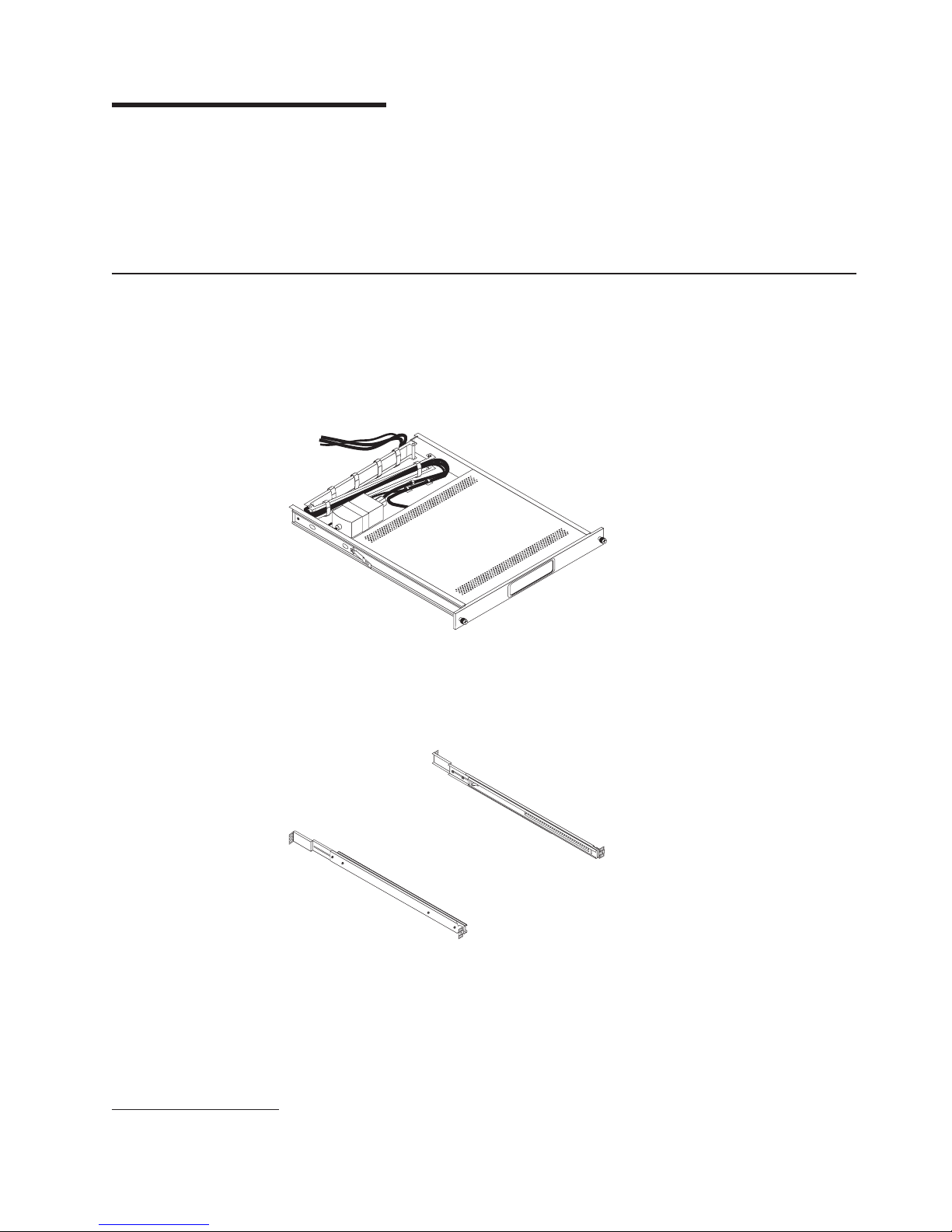
The console kit contains the following items:
v One console unit with built-in flat-panel display and cable-management arm
Important: The ac adapter that is connected to the flat-panel display is not
intended for use with other products. Do not disassemble the
flat-panel display or remove the ac adapter.
v Two outer rails
1. Racks are measured in vertical increments of 1.75 inches each. Each increment is called a “U.” A 1U-high device is 1.75 inches
tall.
© Copyright IBM Corp. 2009 1
Page 12
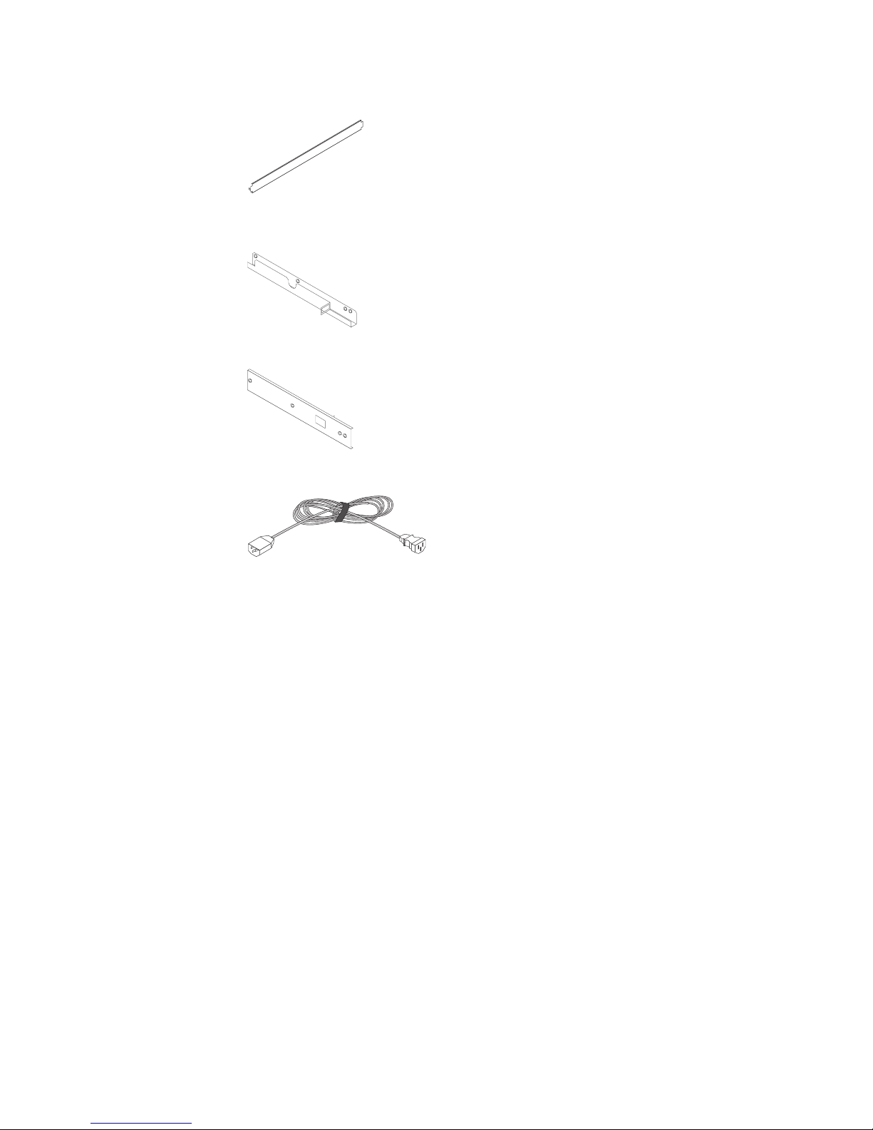
v One rail-alignment spacer
v One console-switch mounting bracket with channel (for routing the power, video,
and keyboard-and-mouse cables)
v One console-switch mounting bracket
v One 2.4 m (8 ft) IEC connector power cable
v Miscellaneous hardware kit (cage nuts, clip nuts, screws, cable straps)
v Hook-and-loop fastener strips to attach a keyboard and keyboard-and-mouse
cables to the console unit
v IBM Documentation CD
You might need the following tools to install the console unit:
v One number 1 Phillips screwdriver
v One number 2 Phillips screwdriver
v One cage-nut-insertion tool or flat-blade screwdriver (for installing cage nuts in
some rack cabinets)
need the following tools to replace customer replaceable units:
You
v One 7/16-inch wrench (for removing the cable-management-arm retaining nut)
v One 1/4-inch wrench (for removing the inner slide rails from the console unit)
the documentation that comes with your rack cabinet or console switch for
See
further information about those products.
2 1U 17-inch Flat Panel Console Kit: Installation and Maintenance Guide
Page 13

The IBM Documentation CD
The IBM Documentation CD contains documentation for the console unit in Portable
Document Format (PDF) and includes the IBM Documentation Browser to help you
find information quickly.
Hardware and software requirements
The IBM Documentation CD requires the following minimum hardware and
software:
v Microsoft® Windows® XP, Windows 2000, or Red Hat Linux
v 100 MHz microprocessor
v 32 MB of RAM
v Adobe Acrobat Reader 3.0 (or later) or xpdf, which comes with Linux operating
systems
Using the Documentation Browser
Use the Documentation Browser to browse the contents of the CD, read brief
descriptions of the documents, and view documents, using Adobe Acrobat Reader
or xpdf. The Documentation Browser automatically detects the regional settings in
use in your server and displays the documents in the language for that region (if
available). If a document is not available in the language for that region, the
English-language version is displayed.
®
Use one of the following procedures to start the Documentation Browser:
v If Autostart is enabled, insert the CD into the CD or DVD drive. The
Documentation Browser starts automatically.
v If Autostart is disabled or is not enabled for all users, use one of the following
procedures:
– If you are using a Windows operating system, insert the CD into the CD or
DVD drive and click Start --> Run. In the Open field, type
e:\win32.bat
where e is the drive letter of the CD or DVD drive, and click OK.
– If you are using Red Hat Linux, insert the CD into the CD or DVD drive; then,
run the following command from the /mnt/cdrom directory:
sh runlinux.sh
Select the console unit from the Product menu. The Available Topics list displays
all the documents for the console unit. Some documents might be in folders. A plus
sign (+) indicates each folder or document that has additional documents under it.
Click the plus sign to display the additional documents.
When you select a document, a description of the document is displayed under
Topic Description. To select more than one document, press and hold the Ctrl key
while you select the documents. Click View Book to view the selected document or
documents in Acrobat Reader or xpdf. If you selected more than one document, all
the selected documents are opened in Acrobat Reader or xpdf.
To search all the documents, type a word or word string in the Search field and
click Search. The documents in which the word or word string appears are listed in
order of the most occurrences. Click a document to view it, and press Crtl+F to use
the Acrobat search function, or press Alt+F to use the xpdf search function within
the document.
Chapter 1. Introduction 3
Page 14

Click Help for detailed information about using the Documentation Browser.
Notices and statements in this document
The caution and danger statements in this document are also in the multilingual
Safety Information document. Each statement is numbered for reference to the
corresponding statement in the Safety Information document.
The following notices and statements are used in this document:
v Note: These notices provide important tips, guidance, or advice.
v Important: These notices provide information or advice that might help you avoid
inconvenient or problem situations.
v Attention: These notices indicate potential damage to programs, devices, or
data. An attention notice is placed just before the instruction or situation in which
damage might occur.
v Caution: These statements indicate situations that can be potentially hazardous
to you. A caution statement is placed just before the description of a potentially
hazardous procedure step or situation.
v Danger: These statements indicate situations that can be potentially lethal or
extremely hazardous to you. A danger statement is placed just before the
description of a potentially lethal or extremely hazardous procedure step or
situation.
4 1U 17-inch Flat Panel Console Kit: Installation and Maintenance Guide
Page 15
Chapter 2. Installing the console unit in the rack cabinet
The console unit occupies 1U of mounting space in a rack cabinet. If you have an
IBM rack cabinet, you can use the brackets that come with this kit to install an
optional console switch in the same 1U of space.
To install the console unit in the rack cabinet, complete the steps in the following
sections. Removing the rack doors and side panels might make installation easier.
See the documentation that comes with your rack cabinet for additional information.
Statement 1:
DANGER
Electrical
current from power, telephone, and communication cables is
hazardous.
To avoid a shock hazard:
v Do not connect or disconnect any cables or perform installation,
maintenance, or reconfiguration of this product during an electrical
storm.
v Connect all power cords to a properly wired and grounded electrical
outlet.
v Connect to properly wired outlets any equipment that will be attached to
this product.
v When possible, use one hand only to connect or disconnect signal
cables.
v Never turn on any equipment when there is evidence of fire, water, or
structural damage.
v Disconnect the attached power cords, telecommunications systems,
networks, and modems before you open the device covers, unless
instructed otherwise in the installation and configuration procedures.
v Connect and disconnect cables as described in the following table when
installing, moving, or opening covers on this product or attached
devices.
To Connect: To Disconnect:
1. Turn everything OFF.
2. First, attach all cables to devices.
3. Attach signal cables to connectors.
4. Attach power cords to outlet.
5. Turn device ON.
© Copyright IBM Corp. 2009 5
1. Turn everything OFF.
2. First, remove power cords from outlet.
3. Remove signal cables from connectors.
4. Remove all cables from devices.
Page 16
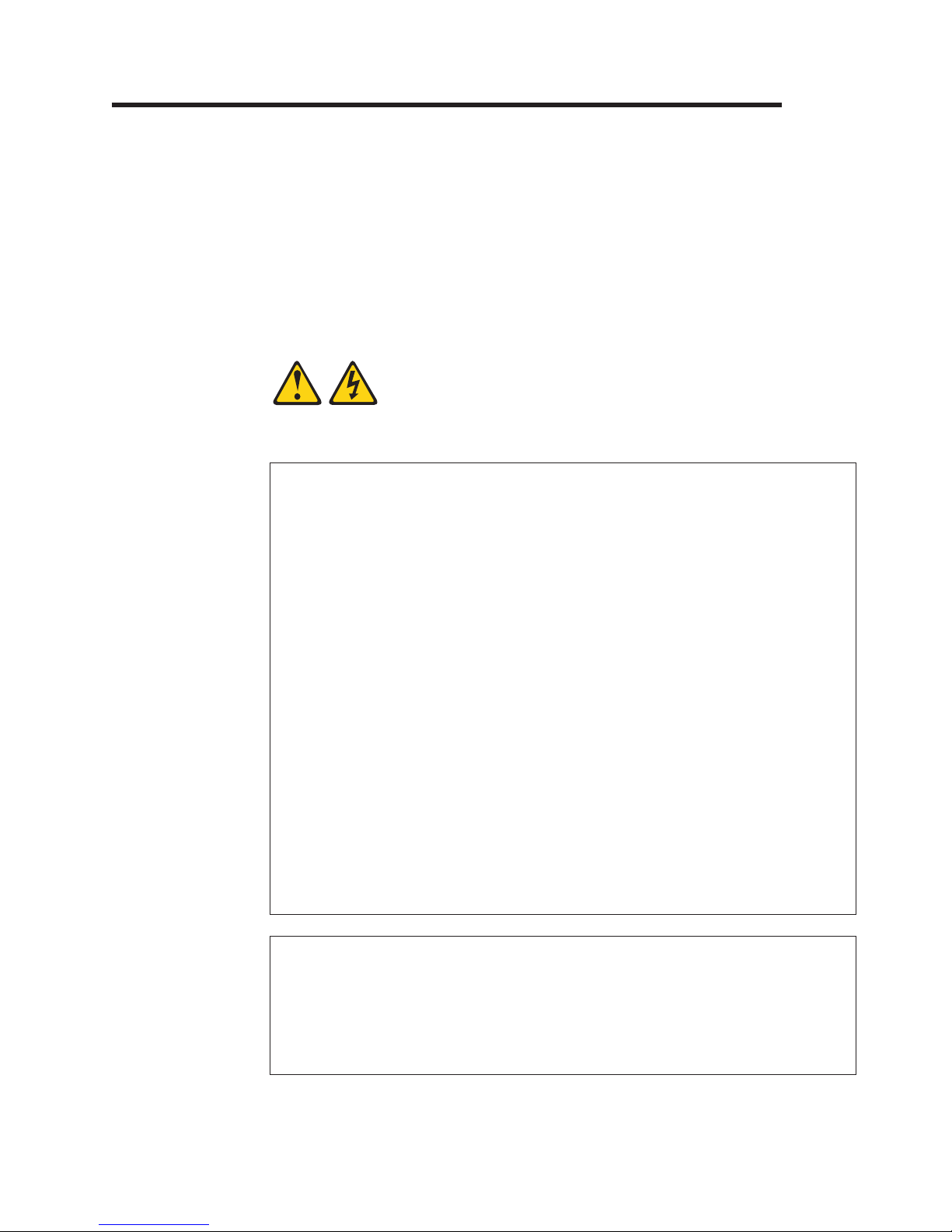
Installing the keyboard in the console unit
To install the keyboard in the console unit, complete the following steps:
1. Place the console unit on a table or other flat surface and make sure that the
right side of the unit extends approximately 76 mm (3 in.) over the edge of the
surface. This will help you route the keyboard-and-mouse cable more easily
later in the procedure. (See the illustration in step 5 on page 7.)
2. Carefully lift the flat-panel display to the full upright position.
3. If the keyboard that you are installing comes with two rubber pads on the
Thumbscrews
underside of the keyboard, remove and discard them. (The rubber pads have
an adhesive backing and can be peeled from the surface.) If you leave the
rubber pads on the keyboard, they will extend into the 1U space below.
Remove rubber pads
(two places)
Keyboard foot
Attention: Do not extend the keyboard feet. The flat-panel display screen
might be damaged if the feet are extended when the display is closed.
4. Peel the protective strip from the hook-and-loop fastener strip that comes with
the console kit and attach it to the underside of the keyboard toward the front.
Hook-and-loop fastener
6 1U 17-inch Flat Panel Console Kit: Installation and Maintenance Guide
Page 17
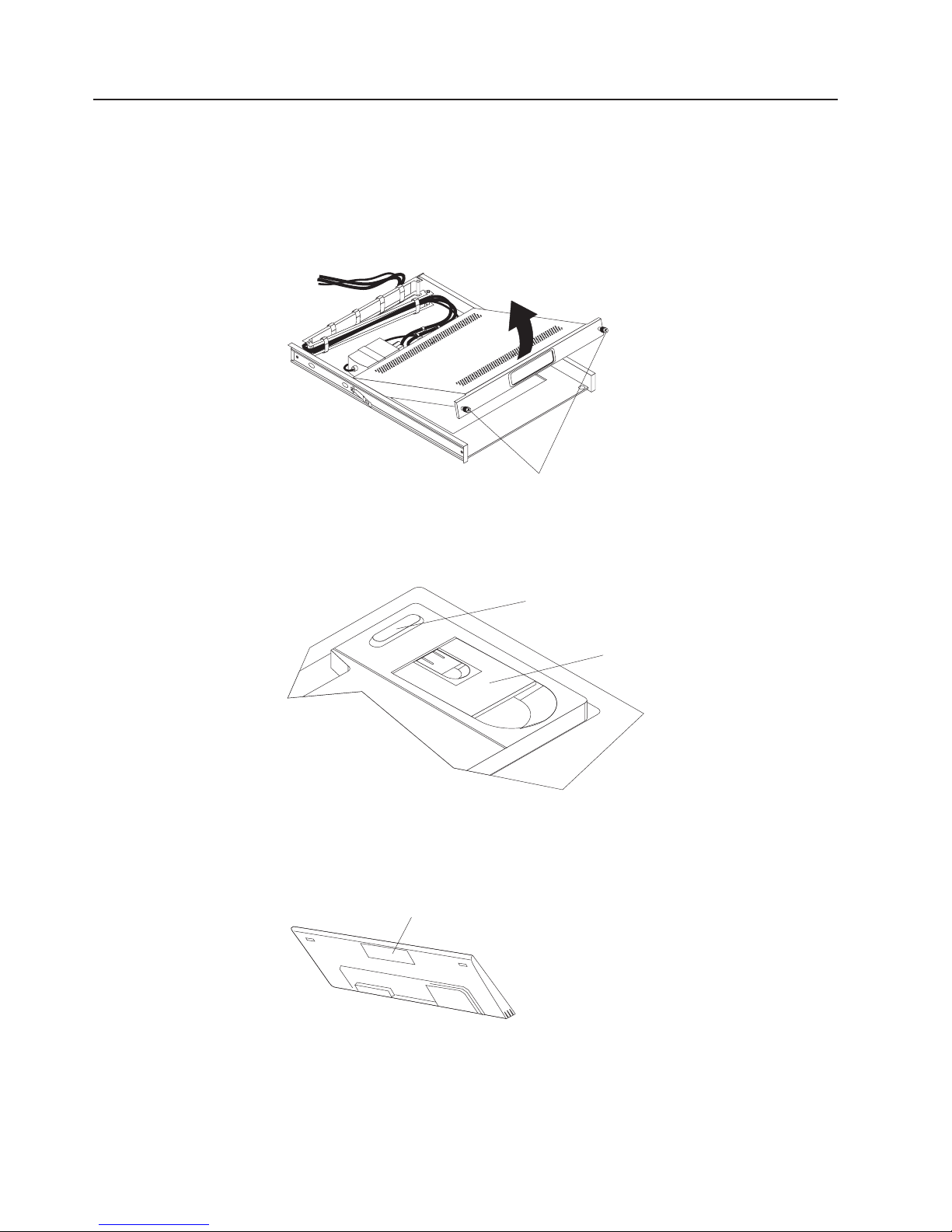
5. Carefully route the keyboard-and-mouse cable down through the keyboard tray
opening, up through the opening on the right side of the tray, and toward the
cable-management arm. Pull the full length of the cable through the opening.
6. Place the keyboard in the tray and press the hook-and-loop fasteners together.
7. Close the flat-panel display.
8. Turn over the console unit:
Hook-and-loop fastener
a. Grasp the cable-management arm and the loose cables in one hand.
b. On the opposite end of the console unit, grasp the flat-panel display and
the console unit frame together with the other hand.
c. Carefully turn over the console unit.
Attention: When you route the keyboard-and-mouse cable, make sure that
the cable does not hang below the underside of the keyboard where it might
be damaged if it interferes with the devices in the rack space below the
console unit.
Chapter 2. Installing the console unit in the rack cabinet 7
Page 18
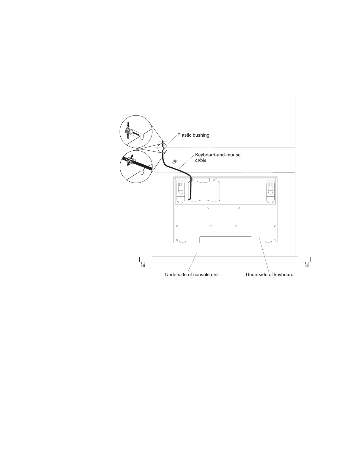
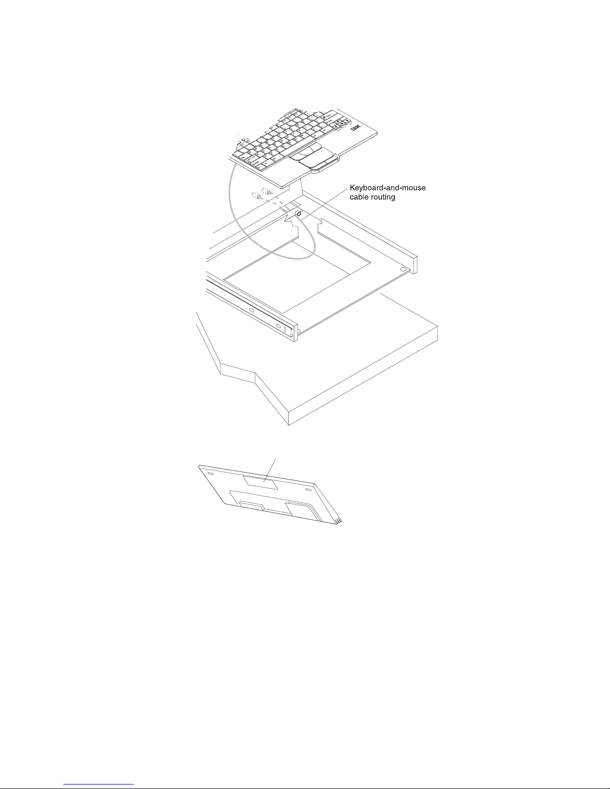
9. Route the keyboard-and-mouse cable:
a. Route the cable through the slot on the left side of the cable-routing area
on the underside of the keyboard. Do not route the cable through any of
the other three slots. (See the following illustration.)
In the following illustration, the console unit is turned over and is
Note:
placed on a table or other flat surface.
b. Gently squeeze the bushing and push it toward the rear of the console unit
to remove it.
c. Push the keyboard-and-mouse cable through the slit in the plastic bushing
and push the bushing into the cable-routing cutout in the console unit
frame.
8 1U 17-inch Flat Panel Console Kit: Installation and Maintenance Guide
Page 19
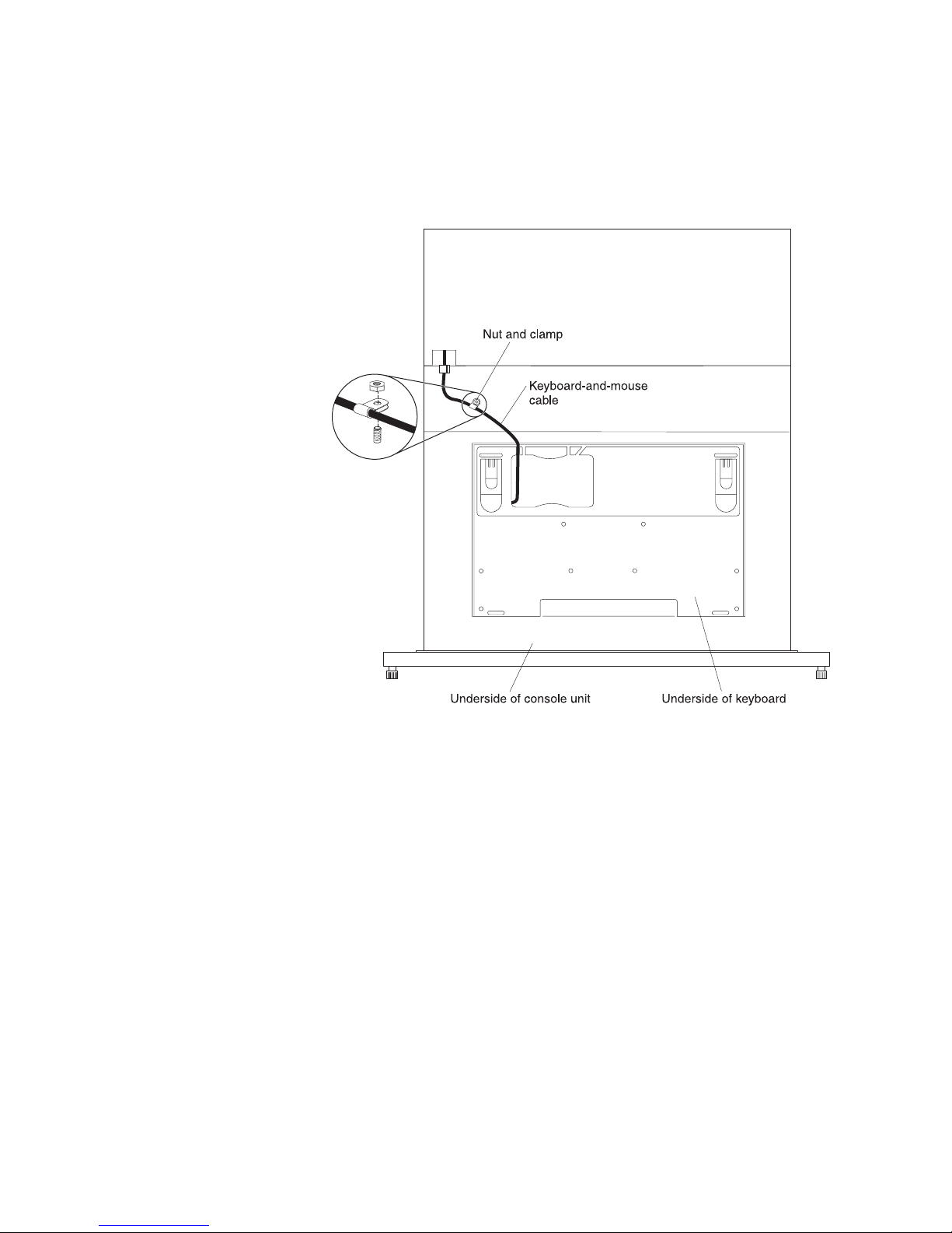
10. Secure the keyboard-and-mouse cable to the console unit with the nut and
clamp:
a. Unscrew the nut and remove the clamp.
Note: In the following illustration, the console unit is turned over and is
placed on a table or other flat surface.
b. Push the keyboard-and-mouse cable into the clamp.
Important:
Make sure that you place the clamp on the
keyboard-and-mouse cable approximately 70 - 76 mm (2.75 -
3 in.) from where the cable exits the keyboard. This prevents
the cable from hanging below the bottom of the console unit.
c. Place the clamp on the screw on the console unit frame and hand-tighten
the nut on top of the clamp.
11. Turn over the console unit:
a. Grasp the cable-management arm and the loose cables in one hand.
b. On the opposite end of the console unit, grasp the flat-panel display and
the console unit frame together with the other hand.
c. Carefully turn over the console unit.
Route the keyboard-and-mouse cable through the cable management arm in
12.
the extended position to avoid strain on the cables. Secure the cable with the
hook-and-loop fasteners.
Chapter 2. Installing the console unit in the rack cabinet 9
Page 20
Installing the console unit in the rack cabinet
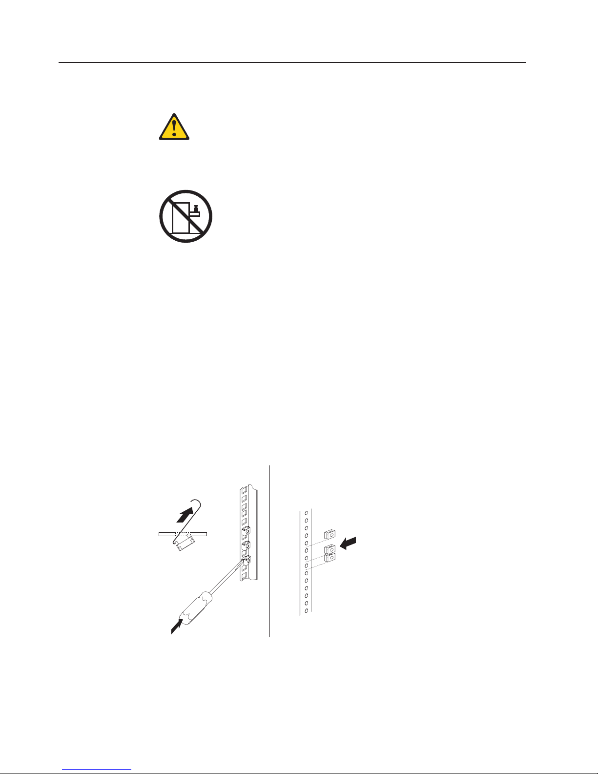
Statement 26:
CAUTION:
Do not place any object on top of rack-mounted devices.
Review the documentation that comes with your rack cabinet for safety and cabling
information. When you install your system in a rack cabinet, observe the following
guidelines:
v Make sure that the room air temperature is below 35°C (95°F).
v Do not block any air vents; usually 15 cm (6 in.) of air space provides proper
airflow.
v Plan the device installation starting from the bottom of the rack cabinet.
v Install the heaviest device in the bottom of the rack cabinet.
v Do not extend more than one device out of the rack cabinet at the same time.
v Connect all power cords to properly wired and grounded electrical outlets.
v Do not overload the power outlet when you install multiple devices in the rack.
cage nuts for rack cabinets with square holes. Use clip nuts for rack cabinets
Use
with round holes. If your rack cabinet requires cage nuts, use a cage-nut-insertion
tool or a flat-blade screwdriver to install them.
Cage
nuts
Cage
Clip
nuts
nuts
To install the console unit in the rack cabinet, complete the following steps:
1. Place the console unit on a stable, flat surface.
Attention: The video cable is connected to the flat-panel display. As you
install the console unit in the rack cabinet, be careful that you do not pinch or
cut the video cable.
10 1U 17-inch Flat Panel Console Kit: Installation and Maintenance Guide
Page 21
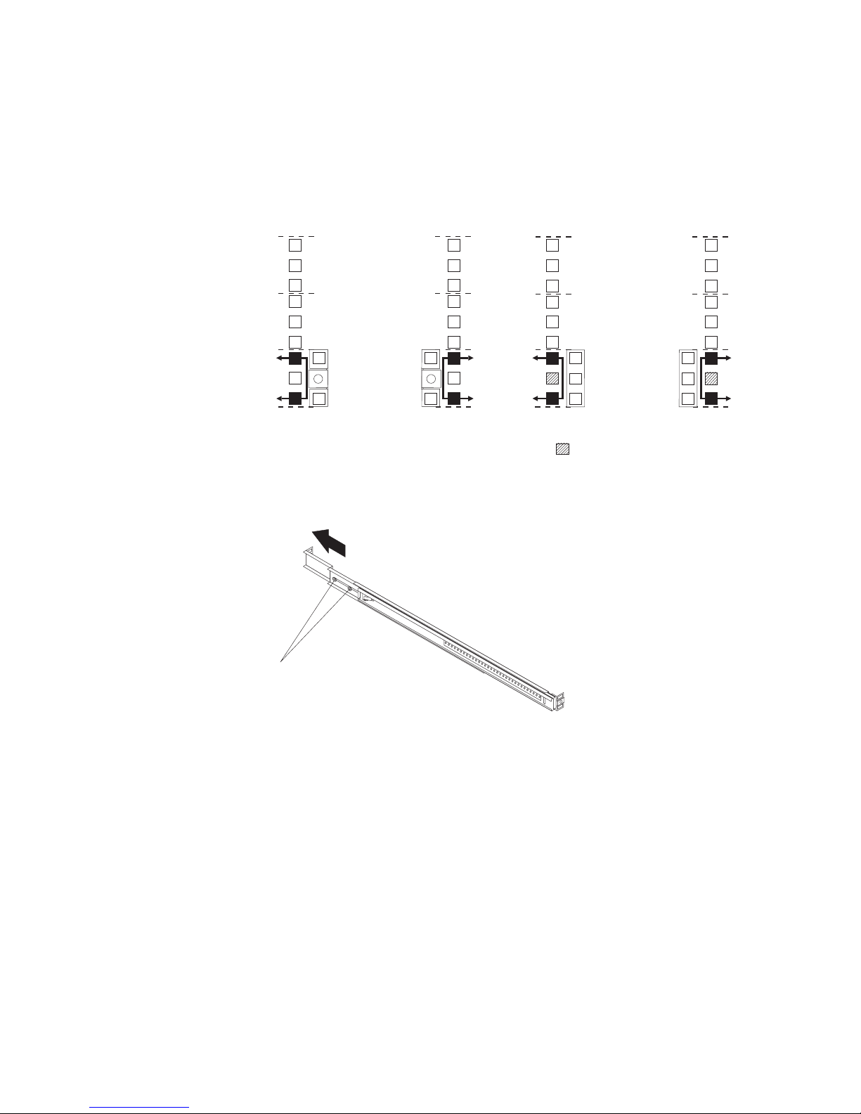
2. Select a 1U location in the rack for the console unit. Install either three cage
nuts or three clip nuts in the front of the rack. Install two cage nuts or two clip
nuts in the rear of the rack. Use the cage nuts or clip nuts from the
miscellaneous hardware kit.
Note: If you are installing an optional console switch behind the console unit,
make sure that you install a cage nut or clip nut in the center-rear
position that is shown shaded in the following illustration.
UUUU
UUUUU
U
U
U
Front Rear
3. If you are installing the console unit in an IBM rack cabinet, no adjustment is
Optional console-switch nut
necessary. Otherwise, loosen the two rail-adjustment screws on each of the
outer slide rails and extend the rails to their maximum outward position.
Rail-adjustment
screws
Chapter 2. Installing the console unit in the rack cabinet 11
Page 22
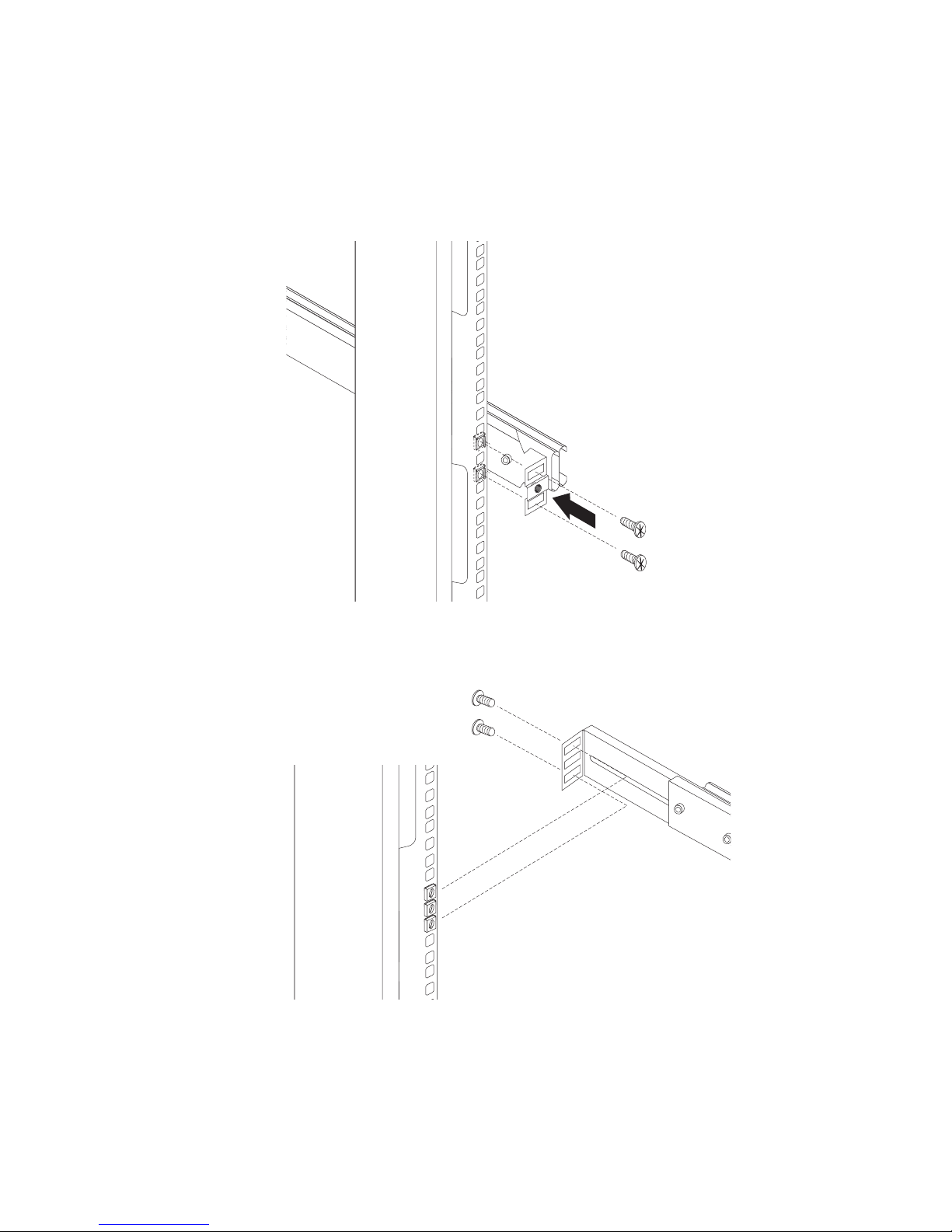
4. Adjust the outer slide-rail brackets to fit the depth of the rack cabinet, and then
attach the front of the slide-rail brackets to the rack cabinet, using four screws
from the miscellaneous hardware kit. Make sure that the slide-rail brackets
extend outside of the rack-cabinet mounting flanges.
Note: Do not install screws in the middle holes in the slide-rail bracket. These
holes are for the thumbscrews on the front of the console unit.
5. Loosely attach the back of the slide-rail brackets to the rack cabinet, using four
screws from the miscellaneous hardware kit. Make sure that the slide-rail
brackets extend outside of the rack-cabinet mounting flanges.
6. Tighten the two rail-adjustment screws on each of the outer rails if you
loosened them in step 3 on page 11.
12 1U 17-inch Flat Panel Console Kit: Installation and Maintenance Guide
Page 23
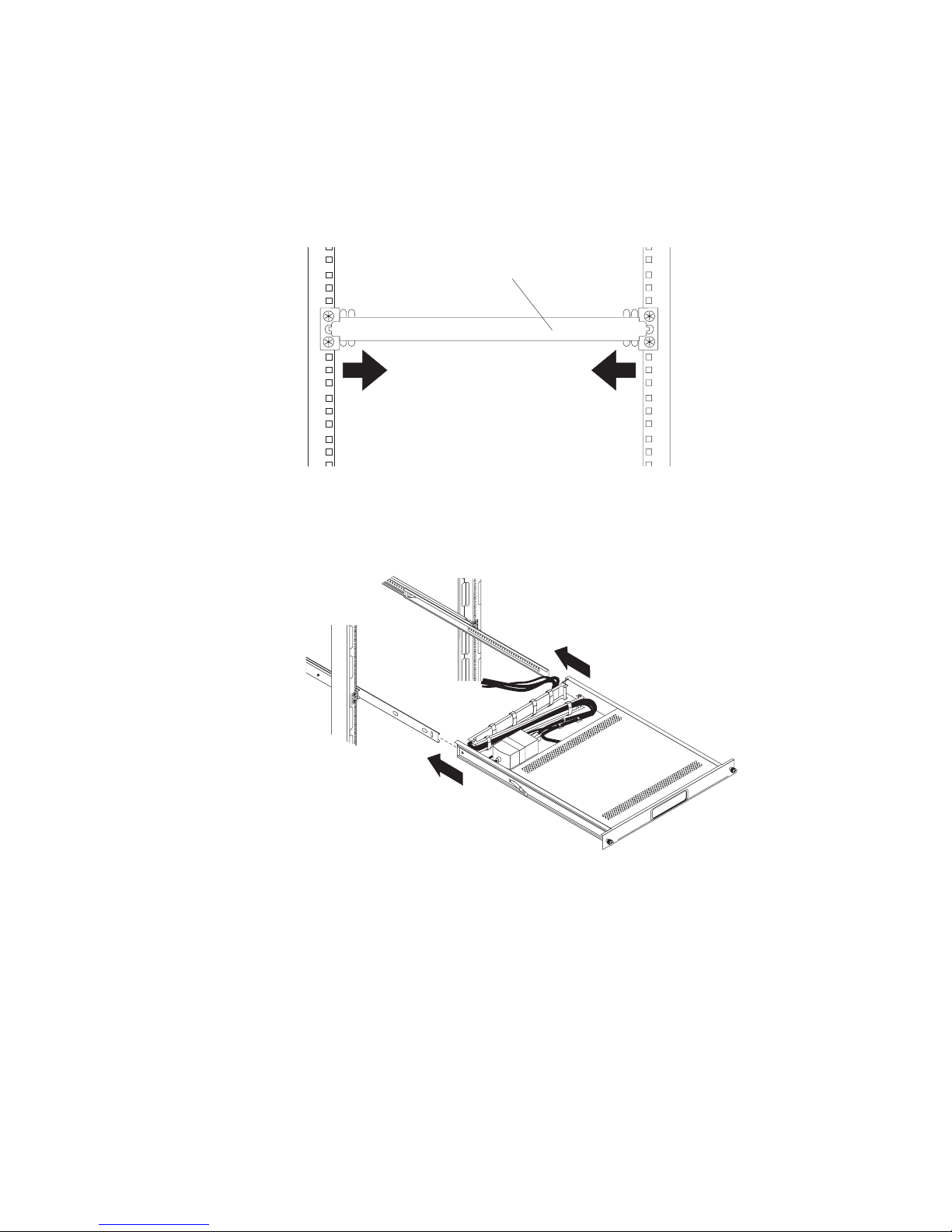
7. Loosen the front four slide-rail bracket screws, and then insert the
rail-alignment spacer into the middle holes in the slide rails. The rail-alignment
spacer must wrap around the rails to align them correctly. Tighten the front four
screws and remove the spacer.
Note: Do not tighten the four rear slide-rail bracket screws at this time.
Rail-alignment spacer
8. Extend the inner part of the outer rails and slide the ball-bearing assemblies
forward to the front of the outer rails. Carefully slide the console unit into the
ball-bearing assemblies in the rails.
Chapter 2. Installing the console unit in the rack cabinet 13
Page 24
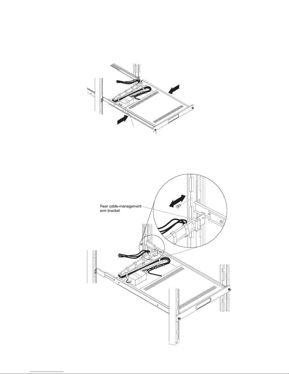
9. Press the release latches, and then push the console unit completely into the
Release latch
rack. There will be resistance initially as the ball-bearing assemblies align
between the inner and outer rails. Pull the console unit out halfway, and then
push it back in to seat the console unit in the rails. Do this a few times until the
console unit moves smoothly in the rails.
10. Push the console unit into the rack, and then tighten the four rear slide-rail
bracket screws.
11. Remove the rail-adjustment screw that is closest to the rear of the rack from
the outer slide-rail bracket. Attach the cable-management arm to the outer
slide-rail bracket, using this screw.
14 1U 17-inch Flat Panel Console Kit: Installation and Maintenance Guide
Page 25
12. Connect the video, keyboard, and mouse connectors to either a server or a
console switch in the rack cabinet. Connect the power cord to the short jumper
cord on the cable-management arm, and then connect the power cord to a
properly grounded electrical outlet or power distribution unit (PDU).
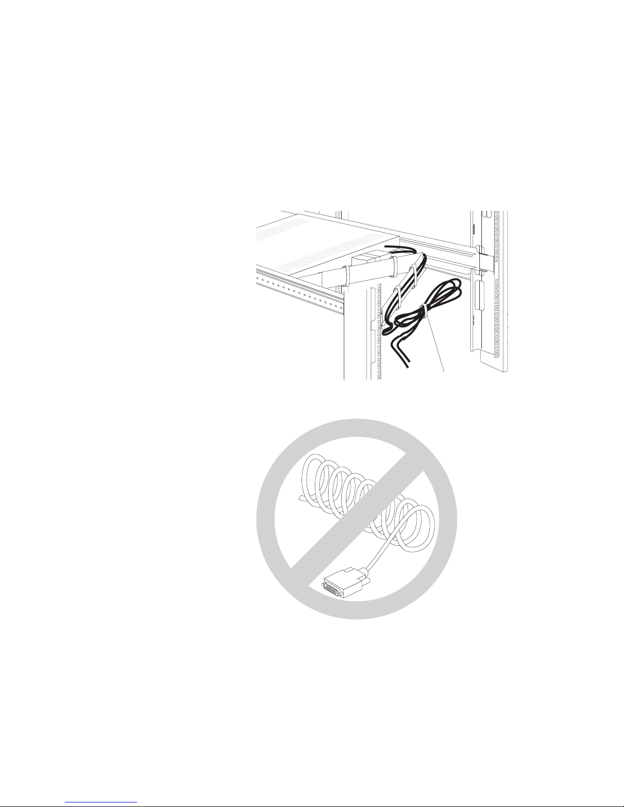
13. Fully extend the console unit from the front of the rack cabinet, and then neatly
route the cables within the rack cabinet and secure them with cable straps
along the way.
Important: To minimize the electrical interference from the video cable,
arrange the cable in figure-eight loops, as shown in the following
illustration. Secure the cable in the middle with a cable strap.
Cable tie
Do not coil the video cable as shown in the following illustration.
14. See Chapter 3, “TFT-LCD display” for information about operating the display.
See the keyboard documentation for information about operating the keyboard.
Chapter 2. Installing the console unit in the rack cabinet 15
Page 26
Note: When the display and keyboard are not in use, if the rack cabinet is in a
vibration-prone area, or during cabinet relocation, tighten the two
thumbscrews on the front of the console unit to secure it inside the rack
cabinet.
Thumbscrew
Installing an optional console switch behind the console unit
You can use a console switch to attach more than one server to a single display
and keyboard. The optional console switch is available separately.
Depending on the depth of the console switch and the depth of the rack, you can
mount the console switch behind the console unit in the same 1U space. To mount
the console switch behind the console unit, use the custom mounting brackets that
come with the console unit.
Use the brackets and instructions that come with the console switch for other
installation options.
Important: The console switch extends beyond the rear rack-cabinet mounting
flanges when you install the switch behind the console unit.
16 1U 17-inch Flat Panel Console Kit: Installation and Maintenance Guide
Page 27
To install a console switch behind the console unit, complete the following steps.
Note: In this procedure, left and right refer to orientations as you are facing the
rear of the rack.
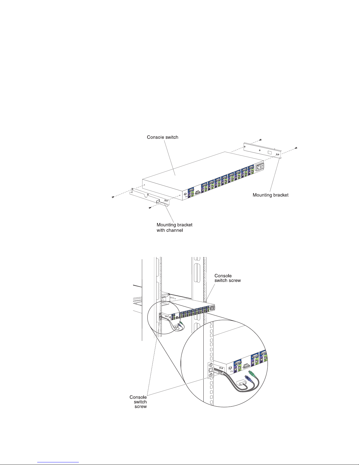
1. Attach the mounting bracket with channel to the left side of the console switch,
using two 8-32 screws, and then attach the other mounting bracket to the right
side of the console switch.
Note: The mounting bracket that you attach to the left side of the console
switch has a channel through which you can route the power, video, and
keyboard-and-mouse cables. Make sure that you attach the bracket to
the console switch so that the channel on the mounting bracket faces
upward.
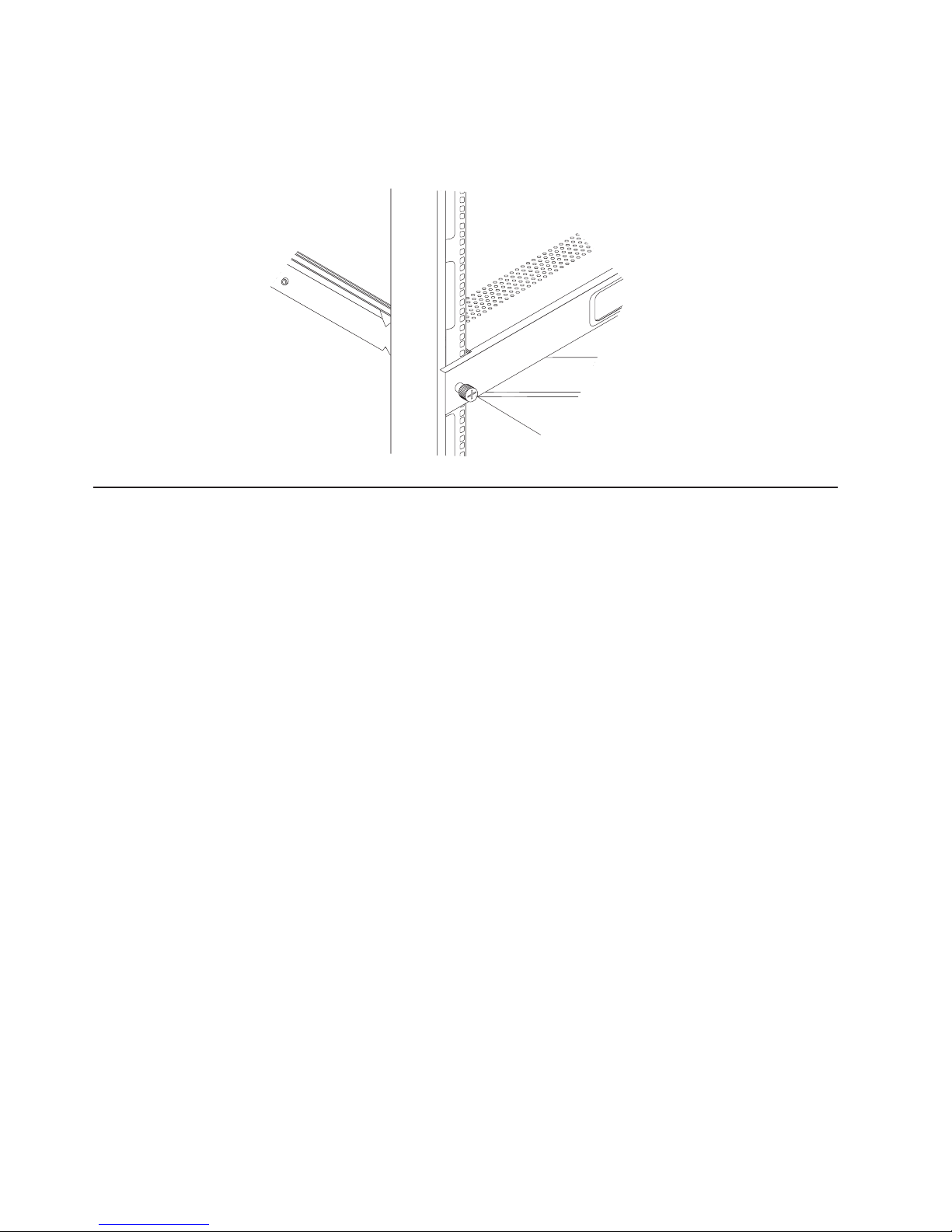
2. Install the console switch behind the console unit, using two screws from the
miscellaneous hardware kit.
Chapter 2. Installing the console unit in the rack cabinet 17
Page 28

3. Route the power, video, and keyboard-and-mouse cables through the channel in
the mounting bracket on the left side of the console switch, and then connect
the video, keyboard, and mouse connectors to the console switch.
4. See the documentation that comes with the console switch for information about
connecting the flat-panel display, thin keyboard, and servers to the console
switch.
18 1U 17-inch Flat Panel Console Kit: Installation and Maintenance Guide
Page 29

Chapter 3. TFT-LCD display
This chapter contains basic information about using the TFT-LCD display. For most
applications, the factory default settings on the display do not require adjustment.
You can download the Owner’s Instructions from http://www.osdmanual.com. To find
the correct manual, press the MENU button and match the on-screen display (OSD)
with one of the OSD choices on the Web site. To return the display to the factory
default settings, press and hold the EXIT button for 3 seconds.
User controls
Use the control buttons on the front of the display to adjust the characteristics of the
image that is being displayed. While you use these buttons to adjust the settings,
an OSD menu displays their numeric values as the settings change.
The user controls on the front of the LCD display function as detailed in the
following list.
AUTO EXIT MENU
v AUTO button: Press this button to automatically adjust the display settings.
v EXIT button: Press this button to exit from the OSD function or go back to the
previous menu.
v Power indicator: Indicates the status of the display operation.
– Green: Normal operation
– Black: Power is off
Power button: Press this button to turn on and turn off the display power.
v
v Left arrow and right arrow buttons (
):
– Press the right arrow button to select the function that is to be adjusted.
– Press the left arrow or right arrow button to decrease or increase the value of
the selected adjustment or to select the correct setting.
– Brightness ( ): Press the left arrow or right arrow button to adjust the
brightness of the back light lamp without using the OSD menu.
MENU button: Press this button to display the OSD menu and to move the
v
selector on the OSD menu.
© Copyright IBM Corp. 2009 19
Page 30

Maintaining the TFT-LCD display
Statement 8:
CAUTION:
Never remove the cover on a power supply or any part that has the following
label attached.
Hazardous voltage, current, and energy levels are present inside any
component that has this label attached. There are no serviceable parts inside
these components. If you suspect a problem with one of these parts, contact
a service technician.
Before you perform any maintenance on the display, turn off the power. Observe the
following guidelines when you clean the display:
v Gently wipe the device covers and the screen with a soft cloth.
v Remove finger marks and grease with a damp cloth and mild detergent; do not
use solvents or abrasives.
v Never use flammable cleaning material to clean an IBM display or any other
electronic device.
20 1U 17-inch Flat Panel Console Kit: Installation and Maintenance Guide
Page 31

Technical specifications
LCD panel
Size 17.0 inch diagonal
Display area (horizontal x vertical) 337.92 x 270.332 mm
Type TFT active matrix
Pixel pitch (horizontal x vertical) 0.264 x 0.264 mm
Frequency
Horizontal 30 - 79 kHz
Vertical 50 - 77 Hz
Display color 16.7 M colors
Display resolution
Optimum mode 1280 x 1024 at 60 Hz
Maximum mode 1280 x 1024 at 75 Hz
Input signal
Sync HN separate, TTL, positive or negative
HN composite, TTL, positive or negative
Sync-on-green 0.3 Vp-p, negative
Video signal 0.700 Vp-p at 75 ohm, positive
Power supply ac 100 - 240 V, 60 Hz - 50 Hz to
dc 12 V/ 5.0 A
Power consumption
Normal Less than 36 watts
Power saving Less than 2 watts
Environmental conditions
Operating temperature (0°C to 50°C)
Operating humidity 10% to 80%
Operating altitude Maximum 3000 meters
Storage temperature (-20°C to +60°C)
Storage humidity 5% to 95%
Storage altitude Maximum 3000 meters
Chapter 3. TFT-LCD display 21
Page 32

22 1U 17-inch Flat Panel Console Kit: Installation and Maintenance Guide
Page 33

Chapter 4. Hardware maintenance information
This chapter contains information about IBM customer-replaceable units (CRUs) for
the console unit and instructions for replacement parts that are not installed during
a typical installation.
Customer-replaceable unit part numbers
IBM CRU part numbers are subject to change without notice. This section contains
a listing of the CRU part numbers that are available as of the date of this printing.
Cable-management arm
p
U
g
P
D
e
g
m
P
o
H
d
t
r
n
e
E
s
n
I
te
B
le
e
e
s
D
u
Pa
+
k
2
=
}
1
rL
F
c
S
_
1
c
1
-
{
S
t
F
r
P
[
0
1
F
P
0
:
9
F
;
O
9
L
8
F
I
8
>
K
7
F
U
7
<
J
6
F
5
F
4
F
4
3
F
3
E
c
2
s
F
E
2
W
1
S
F
1
Q
~
A
`
k
Z
c
b
o
L
Ta
s
p
a
C
t
f
i
h
r
S
t
C
n
F
,
t
Y
l
6
M
A
H
T
5
N
G
R
B
F
V
D
C
X
t
l
A
l
n
e
c
a
p
s
k
c
a
|
\
r
e
t
n
]
E
ft
i
h
“
S
‘
?
/
l
r
t
.
C
Keyboard
Monitor/keyboard
Outer slide rails
CRU part number Description
tray
Inner slide rails
46M5215 IBM 1U 17-inch Flat-Panel Console Kit, without keyboard
46M5328 Slide rails (inner and outer rails, slide alignment spacer)
46M5330 Cable-management arm
46M5331 Miscellaneous parts kit
39M5377 One power cord that connects the power supply to a power source,
2.8 m
© Copyright IBM Corp. 2009 23
Page 34

Power cords
For your safety, IBM provides a power cord with a grounded attachment plug to use
with this IBM product. To avoid electrical shock, always use the power cord and
plug with a properly grounded outlet.
IBM power cords used in the United States and Canada are listed by Underwriter’s
Laboratories (UL) and certified by the Canadian Standards Association (CSA).
For units intended to be operated at 115 volts: Use a UL-listed and CSA-certified
cord set consisting of a minimum 18 AWG, Type SVT or SJT, three-conductor cord,
a maximum of 15 feet in length and a parallel blade, grounding-type attachment
plug rated 15 amperes, 125 volts.
For units intended to be operated at 230 volts (U.S. use): Use a UL-listed and
CSA-certified cord set consisting of a minimum 18 AWG, Type SVT or SJT,
three-conductor cord, a maximum of 15 feet in length and a tandem blade,
grounding-type attachment plug rated 15 amperes, 250 volts.
For units intended to be operated at 230 volts (outside the U.S.): Use a cord set
with a grounding-type attachment plug. The cord set should have the appropriate
safety approvals for the country in which the equipment will be installed.
IBM power cords for a specific country or region are usually available only in that
country or region.
IBM power cord part
number Used in these countries and regions
39M5206 China
39M5102 Australia, Fiji, Kiribati, Nauru, New Zealand, Papua New Guinea
39M5123 Afghanistan, Albania, Algeria, Andorra, Angola, Armenia, Austria,
Azerbaijan, Belarus, Belgium, Benin, Bosnia and Herzegovina,
Bulgaria, Burkina Faso, Burundi, Cambodia, Cameroon, Cape
Verde, Central African Republic, Chad, Comoros, Congo
(Democratic Republic of), Congo (Republic of), Cote D’Ivoire
(Ivory Coast), Croatia (Republic of), Czech Republic, Dahomey,
Djibouti, Egypt, Equatorial Guinea, Eritrea, Estonia, Ethiopia,
Finland, France, French Guyana, French Polynesia, Germany,
Greece, Guadeloupe, Guinea, Guinea Bissau, Hungary, Iceland,
Indonesia, Iran, Kazakhstan, Kyrgyzstan, Laos (People’s
Democratic Republic of), Latvia, Lebanon, Lithuania, Luxembourg,
Macedonia (former Yugoslav Republic of), Madagascar, Mali,
Martinique, Mauritania, Mauritius, Mayotte, Moldova (Republic of),
Monaco, Mongolia, Morocco, Mozambique, Netherlands, New
Caledonia, Niger, Norway, Poland, Portugal, Reunion, Romania,
Russian Federation, Rwanda, Sao Tome and Principe, Saudi
Arabia, Senegal, Serbia, Slovakia, Slovenia (Republic of),
Somalia, Spain, Suriname, Sweden, Syrian Arab Republic,
Tajikistan, Tahiti, Togo, Tunisia, Turkey, Turkmenistan, Ukraine,
Upper Volta, Uzbekistan, Vanuatu, Vietnam, Wallis and Futuna,
Yugoslavia (Federal Republic of), Zaire
39M5130 Denmark
39M5144 Bangladesh, Lesotho, Macao, Maldives, Namibia, Nepal,
Pakistan, Samoa, South Africa, Sri Lanka, Swaziland, Uganda
24 1U 17-inch Flat Panel Console Kit: Installation and Maintenance Guide
Page 35

IBM power cord part
number Used in these countries and regions
39M5151 Abu Dhabi, Bahrain, Botswana, Brunei Darussalam, Channel
Islands, China (Hong Kong S.A.R.), Cyprus, Dominica, Gambia,
Ghana, Grenada, Iraq, Ireland, Jordan, Kenya, Kuwait, Liberia,
Malawi, Malaysia, Malta, Myanmar (Burma), Nigeria, Oman,
Polynesia, Qatar, Saint Kitts and Nevis, Saint Lucia, Saint Vincent
and the Grenadines, Seychelles, Sierra Leone, Singapore, Sudan,
Tanzania (United Republic of), Trinidad and Tobago, United Arab
Emirates (Dubai), United Kingdom, Yemen, Zambia, Zimbabwe
39M5158 Liechtenstein, Switzerland
39M5165 Chile, Italy, Libyan Arab Jamahiriya
39M5172 Israel
39M5095 220 - 240 V
Antigua and Barbuda, Aruba, Bahamas, Barbados, Belize,
Bermuda, Bolivia, Brazil, Caicos Islands, Canada, Cayman
Islands, Colombia, Costa Rica, Cuba, Dominican Republic,
Ecuador, El Salvador, Guam, Guatemala, Haiti, Honduras,
Jamaica, Japan, Mexico, Micronesia (Federal States of),
Netherlands Antilles, Nicaragua, Panama, Peru, Philippines,
Taiwan, United States of America, Venezuela
39M5081 110 - 120 V
Antigua and Barbuda, Aruba, Bahamas, Barbados, Belize,
Bermuda, Bolivia, Caicos Islands, Canada, Cayman Islands,
Colombia, Costa Rica, Cuba, Dominican Republic, Ecuador, El
Salvador, Guam, Guatemala, Haiti, Honduras, Jamaica, Mexico,
Micronesia (Federal States of), Netherlands Antilles, Nicaragua,
Panama, Peru, Philippines, Saudi Arabia, Thailand, Taiwan,
United States of America, Venezuela
39M5219 Korea (Democratic People’s Republic of), Korea (Republic of)
39M5199 Japan
39M5068 Argentina, Paraguay, Uruguay
39M5226 India
39M5233 Brazil
Chapter 4. Hardware maintenance information 25
Page 36

Replacing the keyboard
To replace a keyboard in the console unit, complete the following steps:
1. Disconnect the keyboard and mouse connectors from the server or console
switch.
2. Unscrew the thumbscrews, and then fully extend the console unit from the
rack.
3. Carefully unfasten the cable straps and then remove the keyboard-and-mouse
cable from the cable-management arm.
Thumbscrew
26 1U 17-inch Flat Panel Console Kit: Installation and Maintenance Guide
Page 37

4. On the underside of the console unit, unfasten the keyboard-and-mouse cable
from the nut and clamp:
a. Unscrew the nut and remove the clamp.
Note: The following illustration shows the underside of a fully extended
console unit that is installed in a rack.
b. Remove the keyboard-and-mouse cable from the clamp.
c. Save the nut and clamp for use later in this procedure.
Chapter 4. Hardware maintenance information 27
Page 38

5. Remove the plastic split bushing from the cable-routing cutout in the console
unit frame:
a. On the underside of the console unit, gently squeeze the bushing and push
it toward the rear of the console unit to remove it.
Note: The following illustration shows the underside of a fully extended
console unit that is installed in a rack.
b. Remove the keyboard-and-mouse cable from the bushing.
c. Save the bushing for use later in this procedure.
6. Carefully lift the flat-panel display to the full upright position.
7. Remove the keyboard and cable from the console unit.
28 1U 17-inch Flat Panel Console Kit: Installation and Maintenance Guide
Page 39

8. Unpack the replacement keyboard. If the new keyboard comes with two rubber
pads on the underside of the keyboard, remove and discard them. (The rubber
pads have an adhesive backing and can be peeled from the surface.) If you
leave the rubber pads on the keyboard, they will extend into the 1U space
below.
Remove rubber pads
(two places)
Keyboard foot
Attention: Do not extend the keyboard feet. The flat-panel display screen
might be damaged if the feet are extended when the display is closed.
9. Peel the protective strip from the hook-and-loop fastener strip and attach it
near the front of the underside of the new keyboard.
Hook-and-loop fasteners
Chapter 4. Hardware maintenance information 29
Page 40

10. Carefully route the keyboard-and-mouse cable from the new keyboard down
through the keyboard tray opening, up through the opening on the right side of
the tray, and toward the cable-management arm. Pull the full length of the
cable through the opening.
11. Place the keyboard in the tray and press the hook-and-loop fasteners together.
Attention: When you route the keyboard-and-mouse cable, make sure that
the cable does not hang below the underside of the keyboard where it might
be damaged if it interferes with the devices in the rack space below the
console unit.
30 1U 17-inch Flat Panel Console Kit: Installation and Maintenance Guide
Page 41

12. Route the keyboard-and-mouse cable:
a. Route the cable through the slot on the left side of the cable-routing area
on the underside of the keyboard. Do not route the cable through any of
the other three slots. (See the following illustration.)
The following illustration shows the underside of a fully extended
Note:
console unit that is installed in a rack.
b. Push the keyboard-and-mouse cable through the slit in the plastic bushing
that you removed in step 5 on page 28, and push the bushing into the
cable-routing cutout in the console unit frame.
Chapter 4. Hardware maintenance information 31
Page 42

13. Fasten the keyboard-and-mouse cable to the console unit with the nut and
clamp:
a. Push the keyboard-and-mouse cable into the clamp that you removed in
step 4 on page 27.
Important:
Make sure that you place the clamp on the
keyboard-and-mouse cable approximately 70 - 76 mm (2.75 -
3 in.) from where the cable exits the keyboard. This prevents
the cable from hanging below the bottom of the console unit.
Note: The following illustration shows the underside of a fully extended
console unit that is installed in a rack.
b. Place the clamp on the screw on the console unit frame and hand-tighten
the nut on top of the clamp.
Route the keyboard-and-mouse cable and the other cables through the
14.
cable-management arm. To avoid placing strain on the cables, secure the
cables by using the hook-and-loop fastener cable straps. Make sure that the
cable-management arm is in the extended position when you secure the
cables to it.
15. Reconnect the keyboard-and-mouse cable to the server or console switch.
16. Carefully lift the flat-panel display to the full upright position.
32 1U 17-inch Flat Panel Console Kit: Installation and Maintenance Guide
Page 43

Replacing the cable-management arm
If you installed a console switch in the rear of the rack cabinet, it might be easier to
replace the cable-management arm if you remove the console switch first. To
replace the cable-management arm, complete the following steps:
1. Turn off the display and disconnect the power from the display.
2. Disconnect the keyboard, mouse, and video connectors from the server or
console switch.
3. Remove the screw that attaches the cable-management arm to the outer
slide-rail bracket. Save the screw for use later in the procedure.
4. Fully extend the console unit, and then temporarily remove the
keyboard-and-mouse, video, and power cables from the cable-management
arm.
Chapter 4. Hardware maintenance information 33
Page 44

5. Remove the nut that attaches the front cable-management arm bracket to the
console unit and remove the cable-management arm.
6. Align the new cable-management arm and attach it to the console unit, using
the nut that you removed in step 5.
7. Route the video, power, and keyboard-and-mouse cables along the new
cable-management arm and secure them along the way with cable straps.
34 1U 17-inch Flat Panel Console Kit: Installation and Maintenance Guide
Page 45

8. Attach the cable-management arm to the outer slide-rail bracket, using the
screw that you removed in step 3 on page 33.
9. If you removed a console switch from behind the console unit, reinstall it now.
10. Reconnect the keyboard, mouse, and video connectors to the server or
console switch.
11. Connect power to the display.
Replacing the slide-rail assemblies
Note: To make sure that the slide-rail assemblies fit correctly, replace both the
outer and inner slide rails at the same time.
To replace the outer and inner slide-rails for the console unit, complete the following
steps:
1. Turn off the display and disconnect the power from the display.
2. Disconnect the keyboard, video, and mouse connectors from the server or
console switch.
3. If a console switch is installed in the rear of the rack cabinet, remove the
console switch from the rack.
Chapter 4. Hardware maintenance information 35
Page 46

4. Remove the screw that attaches the cable-management arm to the outer
Release latch
slide-rail bracket. Save the screw for use later in this procedure.
5. Fully extend the console unit from the front of the rack cabinet, push in the
release latch on each side, and slide the console unit out of the rack.
6. Remove the eight screws that attach the outer slide rails to the rack cabinet,
and then remove the old outer slide rails from the cabinet.
36 1U 17-inch Flat Panel Console Kit: Installation and Maintenance Guide
Page 47

7. If you are installing the console unit in an IBM rack cabinet, no adjustment is
necessary. Otherwise, loosen the two rail-adjustment screws on each of the
outer slide rails and extend the rails to their maximum outward position.
Rail-adjustment
screws
8. Adjust the outer slide-rail brackets to fit the depth of the rack cabinet, and then
attach the front of the slide-rail brackets to the rack cabinet, using four screws.
Make sure that the slide-rail brackets extend outside of the rack-cabinet
mounting flanges.
Note: Do not install screws in the middle holes in the slide-rail bracket. These
holes are for the thumbscrews on the front of the console unit.
Chapter 4. Hardware maintenance information 37
Page 48

9. Loosely attach the back of the slide-rail brackets to the rack cabinet, using four
screws. Make sure that the slide-rail brackets extend outside of the
rack-cabinet mounting flanges.
10. Tighten the two rail-adjustment screws on each of the outer rails if you
loosened them in step 7 on page 37.
11. Loosen the front four slide-rail bracket screws, and then insert the
rail-alignment spacer into the middle holes in the slide rail. The rail-alignment
spacer must wrap around the rails to align them correctly. Tighten the front four
screws and remove the spacer.
Rail-alignment spacer
38 1U 17-inch Flat Panel Console Kit: Installation and Maintenance Guide
Page 49

12. Remove the screw and the nut that attach the inner slide rails to the console
unit. Then, attach the corresponding new inner slide rails to the unit, using the
same hardware.
13. Go to step 1 on page 48 for instructions for reinstalling the console unit in the
rack cabinet, and then install any other devices that you removed from the
rack cabinet.
Replacing the console unit in the rack
The procedures that are provided in this section to replace the console unit in the
rack cabinet consist of the following tasks:
1. Removing the existing console unit from the rack cabinet
2. Moving the keyboard from the existing console unit to the replacement console
unit
3. Removing and replacing the outer slide rails
Note: The replacement console unit comes with inner slide rails attached. To
be sure that the slide-rail assemblies fit correctly, replace the existing
outer slide rails with the new rails that come with the replacement
console unit.
4. Installing the replacement console unit in the rack cabinet
Removing the rack doors and side panels might make removal of the existing
console unit and installation of the replacement easier. See the documentation that
comes with the rack cabinet for additional information.
Removing the existing console unit
To remove the existing console unit with keyboard, complete the following steps:
1. Make sure that the two thumbscrews on the front of the console unit are
loosened for removal of the console unit.
2. Turn off the display and disconnect the power cord from the short jumper cord
on the cable-management arm from the electrical outlet or power distribution
unit (PDU). Disconnect the video, keyboard, and mouse connectors from the
server or console switch in the rack cabinet.
Chapter 4. Hardware maintenance information 39
Page 50

3. Remove the screw that attaches the cable-management arm to the outer
Release latch
slide-rail bracket. Save the screw for use in step 4 on page 49.
4. Press the release latches and carefully slide the console unit out of the
ball-bearing assemblies in the rails.
5. Turn over the console unit (so that the underside is facing up) and place it on a
table or other flat surface.
40 1U 17-inch Flat Panel Console Kit: Installation and Maintenance Guide
Page 51

Moving the keyboard
To move the keyboard from the existing console unit to the replacement console
unit, complete the following steps:
1. On the underside of the console unit, unfasten the keyboard-and-mouse cable
from the nut and clamp:
a. Unscrew the nut and remove the clamp.
Note: In the following illustration, the console unit is turned over and is
placed on a table or other flat surface.
b. Remove the keyboard-and-mouse cable from the clamp.
c. Set the nut and clamp aside for use later in this procedure.
Chapter 4. Hardware maintenance information 41
Page 52

2. Remove the plastic split bushing from the cable-routing cutout in the console
unit frame:
a. Gently squeeze the bushing and push it toward the rear of the console unit
to remove it.
In the following illustration, the console unit is turned over and is
Note:
placed on a table or other flat surface.
b. Remove the keyboard-and-mouse cable from the bushing.
c. Save the bushing for use later in this procedure.
3. Turn over the console unit:
a. Grasp the cable-management arm and the loose cables in one hand.
b. On the opposite end of the console unit, grasp the flat-panel display and
the console unit frame together with the other hand.
c. Carefully turn over the console unit.
42 1U 17-inch Flat Panel Console Kit: Installation and Maintenance Guide
Page 53

4. Carefully lift the flat-panel display to the full upright position.
5. Remove the keyboard and cable from the console unit and set it aside.
6. Unpack the replacement console unit and place it on a table or other flat
Thumbscrews
surface. Make sure that the right side of the unit extends approximately 76 mm
(3 in.) over the edge of the surface. This will help you route the
keyboard-and-mouse cable more easily. (See the illustration in step 7.)
7. Carefully route the keyboard-and-mouse cable down through the keyboard tray
opening on the replacement console unit, up through the opening on the right
side of the tray, and toward the cable-management arm. Pull the full length of
the cable through the opening.
8. Place the keyboard in the tray and press the hook-and-loop fasteners together.
9. Close the flat-panel display.
Chapter 4. Hardware maintenance information 43
Page 54

10. Turn over the replacement console unit:
a. Grasp the cable-management arm and the loose cables in one hand.
b. On the opposite end of the console unit, grasp the flat-panel display and
the console unit frame together with the other hand.
c. Carefully turn over the console unit.
Attention: When you route the keyboard-and-mouse cable, make sure that
the cable does not hang below the underside of the keyboard where it might
be damaged if it interferes with the devices in the rack space below the
console unit.
11. Route the keyboard-and-mouse cable:
a. Route the cable through the slot on the left side of the cable-routing area
on the underside of the keyboard. Do not route the cable through any of
the other three slots. (See the following illustration.)
In the following illustration, the console unit is turned over and is
Note:
placed on a table or other flat surface.
b. Push the keyboard-and-mouse cable through the slit in the plastic bushing
that you removed in step 2 on page 42 and push the bushing into the
cable-routing cutout in the console unit frame.
44 1U 17-inch Flat Panel Console Kit: Installation and Maintenance Guide
Page 55

12. Fasten the keyboard-and-mouse cable to the console unit with the nut and
clamp:
a. Push the keyboard-and-mouse cable into the clamp that you removed in
step 1 on page 41.
Important:
Make sure that you place the clamp on the
keyboard-and-mouse cable approximately 70 - 76 mm (2.75 -
3 in.) from where the cable exits the keyboard. This prevents
the cable from hanging below the bottom of the console unit.
Note: In the following illustration, the console unit is turned over and is
placed on a table or other flat surface.
b. Place the clamp on the screw on the console unit frame and hand-tighten
Turn over the console unit:
13.
a. Grasp the cable-management arm and the loose cables in one hand.
b. On the opposite end of the console unit, grasp the flat-panel display and
c. Carefully turn over the console unit.
Route the keyboard-and-mouse cable through the cable-management arm in
14.
the extended position to avoid strain on the cables. Secure the cable with the
hook-and-loop fasteners.
the nut on top of the clamp.
the console unit frame together with the other hand.
Chapter 4. Hardware maintenance information 45
Page 56

Removing and replacing the outer slide rails
To remove and replace the outer slide rails, complete the following steps:
1. Remove the eight screws that attach the outer slide rails to the rack cabinet,
and then remove the old outer slide rails from the cabinet.
2. If you are installing the console unit in an IBM rack cabinet, no adjustment is
necessary. Otherwise, loosen the two rail-adjustment screws on each of the
outer slide rails and extend the rails to their maximum outward adjustment.
Rail-adjustment
screws
3. Adjust the outer slide-rail brackets to fit the depth of the rack cabinet, and then
attach the front of the slide-rail brackets to the rack cabinet, using four screws.
Make sure that the slide-rail brackets extend outside of the rack-cabinet
mounting flanges.
Note: Do not install screws in the middle holes in the slide-rail bracket. These
holes are for the thumbscrews on the front of the console unit.
46 1U 17-inch Flat Panel Console Kit: Installation and Maintenance Guide
Page 57

4. Loosely attach the back of the slide-rail brackets to the rack cabinet, using four
screws. Make sure that the slide-rail brackets extend outside of the rack-cabinet
mounting flanges.
5. Tighten the two rail-adjustment screws on each of the outer rails if you loosened
them in step 2 on page 46.
6. Loosen the front four slide-rail bracket screws, and then insert the rail-alignment
spacer into the middle holes in the slide rail. The rail-alignment spacer must
wrap around the rails to align them correctly. Tighten the front four screws and
remove the spacer.
Rail-alignment spacer
Chapter 4. Hardware maintenance information 47
Page 58

Installing the replacement console unit in the rack cabinet
Release latch
To install the replacement console unit in the rack cabinet, complete the following
steps:
1. Extend the inner part of the outer rails and slide the ball-bearing assemblies
forward to the front of the outer rails. Carefully slide the console unit into the
ball-bearing assemblies in the rails.
2. Press the release latches, and then push the console unit completely into the
rack. There will be resistance initially as the ball-bearing assemblies align
between the inner and outer rails. Pull the console unit out halfway, and then
push it back in to seat the console unit in the rails. Do this a few times until the
console unit moves smoothly in the rails.
3. Push the console unit into the rack.
48 1U 17-inch Flat Panel Console Kit: Installation and Maintenance Guide
Page 59

4. Attach the cable-management arm to the outer slide-rail bracket, using the
screw that you removed in step 3 on page 40.
5. Connect the video, keyboard, and mouse connectors to either a server or a
console switch in the rack cabinet. Connect the power cord to the short jumper
cord on the cable-management arm, and then connect the power cord to a
properly grounded electrical outlet or power distribution unit (PDU).
Chapter 4. Hardware maintenance information 49
Page 60

6. Fully extend the console unit from the front of the rack cabinet, and then neatly
route the cables within the rack cabinet and secure them with cable straps
along the way.
Important: To minimize the electrical interference from the video cable, arrange
the cable in figure-eight loops, as shown in the following illustration.
Secure the cable in the middle with a cable strap.
Cable tie
Do not coil the video cable as shown in the following illustration.
50 1U 17-inch Flat Panel Console Kit: Installation and Maintenance Guide
Page 61

Appendix A. Getting help and technical assistance
If you need help, service, or technical assistance or just want more information
about IBM products, you will find a wide variety of sources available from IBM to
assist you. This section contains information about where to go for additional
information about IBM and IBM products, what to do if you experience a problem
with your system, and whom to call for service, if it is necessary.
Before you call
Before you call, make sure that you have taken these steps to try to solve the
problem yourself:
v Check all cables to make sure that they are connected.
v Check the power switches to make sure that the system and any optional
devices are turned on.
v Use the troubleshooting information in your system documentation, and use the
diagnostic tools that come with your system. Information about diagnostic tools is
in the Problem Determination and Service Guide on the IBM Documentation CD
that comes with your system.
v Go to the IBM support Web site at http://www.ibm.com/systems/support/ to check
for technical information, hints, tips, and new device drivers or to submit a
request for information.
can solve many problems without outside assistance by following the
You
troubleshooting procedures that IBM provides in the online help or in the
documentation that is provided with your IBM product. The documentation that
comes with IBM systems also describes the diagnostic tests that you can perform.
Most systems, operating systems, and programs come with documentation that
contains troubleshooting procedures and explanations of error messages and error
codes. If you suspect a software problem, see the documentation for the operating
system or program.
Using the documentation
Information about your IBM system and preinstalled software, if any, or optional
device is available in the documentation that comes with the product. That
documentation can include printed documents, online documents, readme files, and
help files. See the troubleshooting information in your system documentation for
instructions for using the diagnostic programs. The troubleshooting information or
the diagnostic programs might tell you that you need additional or updated device
drivers or other software. IBM maintains pages on the World Wide Web where you
can get the latest technical information and download device drivers and updates.
To access these pages, go to http://www.ibm.com/systems/support/ and follow the
instructions. Also, some documents are available through the IBM Publications
Center at http://www.ibm.com/shop/publications/order/.
Getting help and information from the World Wide Web
On the World Wide Web, the IBM Web site has up-to-date information about IBM
systems, optional devices, services, and support. The address for IBM System x
and xSeries® information is http://www.ibm.com/systems/x/. The address for IBM
BladeCenter® information is http://www.ibm.com/systems/bladecenter/. The address
for IBM IntelliStation® information is http://www.ibm.com/intellistation/.
© Copyright IBM Corp. 2009 51
™
Page 62

You can find service information for IBM systems and optional devices at
http://www.ibm.com/systems/support/.
Software service and support
Through IBM Support Line, you can get telephone assistance, for a fee, with usage,
configuration, and software problems with System x and xSeries servers,
BladeCenter products, IntelliStation workstations, and appliances. For information
about which products are supported by Support Line in your country or region, see
http://www.ibm.com/services/sl/products/.
For more information about Support Line and other IBM services, see
http://www.ibm.com/services/, or see http://www.ibm.com/planetwide/ for support
telephone numbers. In the U.S. and Canada, call 1-800-IBM-SERV
(1-800-426-7378).
Hardware service and support
You can receive hardware service through your IBM reseller or IBM Services. To
locate a reseller authorized by IBM to provide warranty service, go to
http://www.ibm.com/partnerworld/ and click Find a Business Partner on the right
side of the page. For IBM support telephone numbers, see http://www.ibm.com/
planetwide/.
In the U.S. and Canada, call 1-800-IBM-SERV (1-800-426-7378).
In the U.S. and Canada, hardware service and support is available 24 hours a day,
7 days a week. In the U.K., these services are available Monday through Friday,
from 9 a.m. to 6 p.m.
IBM Taiwan product service
IBM Taiwan product service contact information:
IBM Taiwan Corporation
3F, No 7, Song Ren Rd.
Taipei, Taiwan
Telephone: 0800-016-888
52 1U 17-inch Flat Panel Console Kit: Installation and Maintenance Guide
Page 63

Appendix B. IBM Statement of Limited Warranty Z125-4753-10
08/2008
Part 1 - General Terms
This Statement of Limited Warranty includes Part 1 - General Terms, Part 2 -
Country-unique Terms, and Part 3 - Warranty Information. The terms of Part 2
replace or modify those of Part 1. For purposes of this Statement of Limited
Warranty, “IBM” means the IBM entity that provided your Machine to you or to your
reseller–for example, International Business Machines Corporation in the U.S. or
IBM World Trade Corporation or the local IBM entity in your country.
The warranties provided by IBM in this Statement of Limited Warranty apply only to
Machines you purchase for your use, and not for resale. The term “Machine” means
an IBM machine, its features, conversions, upgrades, elements, or accessories, or
any combination of them. The term “Machine” does not include any software
programs, whether pre-loaded with the Machine, installed subsequently, or
otherwise. NOTHING IN THIS STATEMENT OF LIMITED WARRANTY AFFECTS
ANY STATUTORY RIGHTS OF CONSUMERS THAT CANNOT BE WAIVED OR
LIMITED BY CONTRACT.
This Statement of Limited Warranty is available, in multiple languages, at the
following IBM Internet website: http://www.ibm.com/systems/support/
machine_warranties/.
What this Warranty Covers
IBM warrants that each Machine is free from defects in materials and workmanship
and conforms to its Specifications. “Specifications” is information specific to a
Machine in a document entitled “Official Published Specifications”, which is
available upon request.
During the warranty period, IBM provides repair and exchange service for the
Machine under the type of warranty service IBM designates for the Machine. The
warranty period for the Machine is a fixed period starting on its original Date of
Installation. The date on your purchase invoice or sales receipt is the Date of
Installation unless IBM or your reseller informs you otherwise. The warranty period,
type of warranty, and service level that apply to your Machine are designated in
Part 3.
Many features, conversions, or upgrades involve the removal of parts and their
return to IBM. An IBM part that replaces a removed part will assume the warranty
service status of the removed part. An IBM part that is added to a Machine without
replacing a previously-installed part is subject to warranty effective on its Date of
Installation. Unless IBM specifies otherwise, the warranty period, type of warranty,
and service level of such part is the same as the Machine on which it is installed.
Unless IBM specifies otherwise, these warranties apply only in the country or region
in which you purchased the Machine.
THESE WARRANTIES ARE YOUR EXCLUSIVE WARRANTIES AND REPLACE
ALL OTHER WARRANTIES OR CONDITIONS, EXPRESS OR IMPLIED,
INCLUDING, BUT NOT LIMITED TO, THE IMPLIED WARRANTIES OR
CONDITIONS OF MERCHANTABILITY AND FITNESS FOR A PARTICULAR
PURPOSE, AND ANY WARRANTY OF TITLE OR NON-INFRINGMENT. SOME
© Copyright IBM Corp. 2009 53
Page 64

STATES OR JURISDICTIONS DO NOT ALLOW THE EXCLUSION OF EXPRESS
OR IMPLIED WARRANTIES, SO THE ABOVE EXCLUSION MAY NOT APPLY TO
YOU. IN THAT EVENT, SUCH WARRANTIES ARE LIMITED IN DURATION TO
THE WARRANTY PERIOD. NO WARRANTIES APPLY AFTER THAT PERIOD.
SOME STATES OR JURISDICTIONS DO NOT ALLOW LIMITATIONS ON HOW
LONG AN IMPLIED WARRANTY LASTS, SO THE ABOVE LIMITATION MAY NOT
APPLY TO YOU.
What this Warranty Does not Cover
This warranty does not cover the following:
a. failure or damage resulting from misuse (including, but not limited to, use of any
Machine capacity or capability, other than that authorized by IBM in writing),
accident, modification, unsuitable physical or operating environment, operation in
other than the specified operating environment or improper maintenance by you or
a third party;
b. failure due to events beyond IBM's control;
c. failure caused by a product for which IBM is not responsible;
d. any non-IBM products, including those provided with, or installed on, an IBM
Machine at your request;
e. accessories, supply items and consumables (e.g. batteries and printer cartridges),
and structural parts (e.g. frames and covers);
f. service of Machine alterations; and
g. service of a Machine on which you are using capacity or capability, other than that
authorized by IBM in writing.
The warranty is voided by removal or alteration of identification labels on the
Machine or its parts.
IBM does not warrant uninterrupted or error-free operation of a Machine.
Any technical or other support provided for a Machine under warranty, such as
assistance with “how-to” questions and those regarding Machine set-up and
installation, is provided WITHOUT WARRANTIES OF ANY KIND.
How to Obtain Warranty Service
If the Machine does not function as warranted during the warranty period, refer to
the service documentation that shipped with your Machine for support assistance
and problem determination procedures. A copy of the service documentation for
your Machine can also be found at the following IBM website: http://www.ibm.com
under “Support and downloads”.
If you are unable to resolve your problem with the service documentation, contact
IBM or your reseller to obtain warranty service. Contact information for IBM is
provided in Part 3. If you do not register the Machine with IBM, you may be
required to present proof of purchase as evidence of your entitlement to warranty
service.
What IBM Will Do to Correct Problems
IBM will attempt to diagnose and resolve your problem over the telephone or
electronically by access to an IBM Internet website. Certain Machines contain
54 1U 17-inch Flat Panel Console Kit: Installation and Maintenance Guide
Page 65

remote support capabilities for direct problem reporting, remote problem
determination, and resolution with IBM. When you contact IBM for service, you must
follow the problem determination and resolution procedures that IBM specifies.
Following problem determination, if IBM determines on-site service is required, a
service technician will be scheduled for service at your location.
You are responsible for downloading or obtaining from IBM, and installing
designated Machine Code (microcode, basic input/output system code (called
“BIOS”), utility programs, device drivers, and diagnostics delivered with an IBM
Machine) and other software updates in a timely manner from an IBM Internet
website or from other electronic media, and following the instructions that IBM
provides. You may request IBM to install Machine Code changes, however, you
may be charged for that service.
Some parts of IBM Machines are designated as Customer Replaceable Units
(“CRUs”). If your problem can be resolved with a CRU (e.g. keyboard, memory,
hard disk drive), IBM will ship the CRU to you for you to install.
If the Machine does not function as warranted during the warranty period and your
problem cannot be resolved over the telephone or electronically, through your
application of Machine Code or software updates, or with a CRU, IBM or its
subcontractor or a reseller that has been approved by IBM to provide warranty
service, will either, at its discretion, 1) repair it to make it function as warranted, or
2) replace it with one that is at least functionally equivalent. If IBM or its
subcontractor or the reseller is unable to do either, you may return the Machine to
your place of purchase and your money will be refunded.
IBM or its subcontractor or the reseller will also manage and install selected
engineering changes that apply to the Machine.
Exchange of a Machine or Part
When the warranty service involves the exchange of a Machine or part, the item
IBM or its subcontractor or the reseller replaces becomes IBM’s property, and the
replacement becomes yours. You represent that all removed items are genuine and
unaltered. The replacement may not be new, but will be in good working order and
at least functionally equivalent to the item replaced. The replacement assumes the
warranty service status of the replaced item.
Your Additional Responsibilities
You agree:
a. before IBM or its subcontractor or the reseller exchanges a Machine or part, to
remove all features, parts, options, alterations, and attachments not under warranty
service and ensure that the Machine is free of any legal obligations or restrictions
that prevent its exchange;
b. to obtain authorization from the owner to have IBM or its subcontractor or the
reseller service a Machine that you do not own;
c. where applicable, before service is provided:
1. follow the service request procedures that IBM or its subcontractor or its reseller
provides;
2. backup and secure all programs, data, and funds contained in the Machine; and
3. inform IBM or its subcontractor or the reseller of changes in the Machine’s
location;
Appendix B. IBM Statement of Limited Warranty Z125-4753-10 08/2008 55
Page 66

d. to provide IBM or its subcontractor or the reseller with sufficient and safe access to
your facilities to permit IBM to fulfill its obligations;
e. to allow IBM or its subcontractor or the reseller to install mandatory engineering
changes, such as those required for safety;
f. when the type of warranty service requires that you deliver a failing Machine to
IBM, you agree to ship it suitably packaged, as IBM specifies, to a location IBM
designates. After the Machine has been repaired or exchanged, IBM will return the
repaired Machine or provide a replacement Machine to you at its expense, unless
IBM specifies otherwise. IBM is responsible for loss of, or damage to, your Machine
only while it is 1) in IBM’s possession; or 2) in transit in those cases where IBM is
responsible for the transportation charges; and
g. to securely erase from any Machine you return to IBM for any reason all programs
not provided by IBM with the Machine, and data, including without limitation the
following: 1) information about identified or identifiable individuals or legal entities
(“Personal Data”); and 2) your confidential or proprietary information and other data.
If removing or deleting Personal Data is not possible, you agree to transform such
information (e.g., by making it anonymous or encrypting it) so that it no longer
qualifies as Personal Data under applicable law. Yo u also agree to remove all funds
from Machines returned to IBM. IBM is not responsible for any funds, programs not
provided by IBM with the Machine, or data contained in a Machine that you return
to IBM. You acknowledge that, to perform its responsibilities under this Statement of
Limited Warranty, IBM may ship all or part of the Machine or its software to other
IBM or third party locations around the world, and you authorize IBM to do so.
Limitation of Liability
Circumstances may arise where, because of a default on IBM’s part or other
liability, you are entitled to recover damages from IBM. Regardless of the basis on
which you are entitled to claim damages from IBM (including fundamental breach,
negligence, misrepresentation, or other contract or tort claim), except for any liability
that cannot be waived or limited by applicable laws, IBM's entire liability for all
claims in the aggregate arising from or related to each Product will not exceed:
a. damages for bodily injury (including death) and damage to real property and
tangible personal property; and
b. the amount of any other actual direct damages, up to the charges (if recurring, 12
months’ charges apply) for the Machine that is subject of the claim. For purposes of
this item, the term “Machine” includes Machine Code and Licensed Internal Code
(“LIC”).
This limit also applies to IBM’s suppliers, subcontractors, and resellers. It is the
maximum for which IBM and its suppliers, subcontractors, and resellers are
collectively responsible.
UNDER NO CIRCUMSTANCES IS IBM OR ITS SUPPLIERS,
SUBCONTRACTORS, OR RESELLERS LIABLE FOR ANY OF THE FOLLOWING
EVEN IF INFORMED OF THEIR POSSIBILITY: 1) THIRD PARTY CLAIMS
AGAINST YOU FOR DAMAGES (OTHER THAN THOSE UNDER THE FIRST
ITEM LISTED ABOVE); 2) LOSS OF, OR DAMAGE TO, D ATA ; 3) SPECIAL,
INCIDENTAL, OR INDIRECT DAMAGES OR FOR ANY ECONOMIC
CONSEQUENTIAL DAMAGES; OR 4) LOST PROFITS, BUSINESS, REVENUE,
GOODWILL OR ANTICIPATED SAVINGS. SOME STATES OR JURISDICTIONS
DO NOT ALLOW THE EXCLUSION OR LIMITATION OF INCIDENTAL OR
CONSEQUENTIAL DAMAGES, SO THE ABOVE LIMITATION OR EXCLUSION
MAY NOT APPLY TO YOU.
56 1U 17-inch Flat Panel Console Kit: Installation and Maintenance Guide
Page 67

Governing Law
Both you and IBM consent to the application of the laws of the country in which you
acquired the Machine to govern, interpret, and enforce all of your and IBM’s rights,
duties, and obligations arising from, or relating in any manner to, the subject matter
of this Statement of Limited Warranty, without regard to conflict of law principles.
THESE WARRANTIES GIVE YOU SPECIFIC LEGAL RIGHTS, AND YOU MAY
ALSO HAVE OTHER RIGHTS WHICH VARY FROM STATE TO STATE OR
JURISDICTION TO JURISDICTION.
Jurisdiction
All of our rights, duties, and obligations are subject to the courts of the country in
which you acquired the Machine.
Part 2 - Country-unique Terms
AMERICAS
Jurisdiction:
The following sentence is added to this section as it applies to countries in bold
print below:
Any litigation arising from this Statement of Limited Warranty will be settled
exclusively by 1) in Argentina; the Ordinary Commercial Court of the city of Buenos
Aires; 2) in Bolivia; the courts of the city of La Paz; 3) in Brazil; court of Rio de
Janeiro, RJ; 4) in Chile; the Civil Courts of Justice of Santiago; 5) in Colombia; the
Judges of the Republic of Colombia; 6) in Equador; the civil judges of Quito for
executory or summary proceedings (as applicable); 7) in Mexico; the courts located
in Mexico City, Federal District; 8) in Paraguay; the courts of the city of Asuncion;
9) in Peru; the judges and tribunals of the judicial district of Lima, Cercado; 10) in
Uruguay; the courts of the city of Montevideo; 11) in Venezuela; the courts of the
metropolitan area of the city of Caracas.
BRAZIL
Exchange of a Machine or Part:
Delete the last sentence:
The replacement assumes the warranty service status of the replaced item.
CANADA
What this Warranty Covers:
The following replaces the 2
During the warranty period, IBM provides repair and exchange service for the
Machine under the type of warranty service IBM designates for the Machine. The
warranty period for the Machine is a fixed period starting on its original Date of
Installation. The date on your purchase invoice or sales receipt is the Date of
Installation unless IBM informs you otherwise. The warranty period, type of
warranty, and service level that apply to your Machine are designated in Part 3.
nd
paragraph to this section:
Appendix B. IBM Statement of Limited Warranty Z125-4753-10 08/2008 57
Page 68

Limitation of Liability:
The following replaces item a and item b of this section:
a. damages for bodily injury (including death) or physical harm to real property and
tangible personal property caused by IBM’s negligence; and
b. the amount of any other actual direct damages, up to the greater of $100,000.00 or
the charges (if recurring, 12 months’ charges apply) for the Machine that is subject
of the claim. For purposes of this item, the term “Machine” includes Machine Code
and Licensed Internal Code (“LIC”).
Governing Law:
The following replaces “laws of the country in which you acquired the Machine” in
the first sentence:
laws in the Province of Ontario.
PERU
Limitation of Liability:
The following is added at the end of this section:
In accordance with Article 1328 of the Peruvian Civil Code the limitations and
exclusions specified in this section will not apply to damages caused by IBM’s willful
misconduct (“dolo”) or gross negligence (“culpa inexcusable”).
UNITED STATES
Governing Law:
The following replaces “laws of the country in which you acquired the Machine” in
the first sentence:
laws of the State of New York
ASIA PACIFIC
AUSTRALIA
What this Warranty Covers:
The following paragraph is added to this section:
The warranties specified in this Section are in addition to any rights you may have
under the Trade Practices Act 1974 or other similar legislation and are only limited
to the extent permitted by the applicable legislation.
Limitation of Liability:
The following is added to this section:
Where IBM is in breach of a condition or warranty implied by the Trade Practices
Act 1974 or other similar legislation, IBM’s liability is limited to the repair or
58 1U 17-inch Flat Panel Console Kit: Installation and Maintenance Guide
Page 69

replacement of the goods or the supply of equivalent goods. Where that condition
or warranty relates to right to sell, quiet possession or clear title, or the goods are of
a kind ordinarily acquired for personal, domestic or household use or consumption,
then none of the limitations in this paragraph apply.
Governing Law:
The following replaces “laws of the country in which you acquired the Machine” in
the first sentence:
laws of the State or Territory
CAMBODIA AND LAOS
Governing Law:
The following replaces “laws of the country in which you acquired the Machine” in
the first sentence:
laws of the State of New York, United States of America
CAMBODIA, INDONESIA AND LAOS
Arbitration:
The following is added under this heading:
Disputes arising out of or in connection with this Statement of Limited Warranty
shall be finally settled by arbitration which shall be held in Singapore in accordance
with the Arbitration Rules of Singapore International Arbitration Center (“SIAC
Rules”) then in effect. The arbitration award shall be final and binding for the parties
without appeal and shall be in writing and set forth the findings of fact and the
conclusions of law.
The number of arbitrators shall be three, with each side to the dispute being entitled
to appoint one arbitrator. The two arbitrators appointed by the parties shall appoint
a third arbitrator who shall act as chairman of the proceedings. Vacancies in the
post of chairman shall be filled by the president of the SIAC. Other vacancies shall
be filled by the respective nominating party. Proceedings shall continue from the
stage they were at when the vacancy occurred.
If one of the parties refuses or otherwise fails to appoint an arbitrator within 30 days
of the date the other party appoints its, the first appointed arbitrator shall be the
sole arbitrator, provided that the arbitrator was validly and properly appointed.
All proceedings shall be conducted, including all documents presented in such
proceedings, in the English language. The English language version of this
Statement of Limited Warranty prevails over any other language version.
HONG KONG S.A.R.
As applies to transactions initiated and performed in Hong Kong S.A.R., phrases
throughout this Agreement containing the word “country” (for example, “country of
purchase” and “country of Installation”) are replaced with “Hong Kong S.A.R.”
INDIA
Appendix B. IBM Statement of Limited Warranty Z125-4753-10 08/2008 59
Page 70

Limitation of Liability:
The following replaces item a and item b of this section:
a. liability for bodily injury (including death) or damage to real property and tangible
personal property will be limited to that caused by IBM’s negligence; and
b. as to any other actual damage arising in any situation involving nonperformance by
IBM pursuant to, or in any way related to the subject of this Statement of Limited
Warranty, the charge paid by you for the individual Machine that is the subject of
the claim. For purposes of this item, the term “Machine” includes Machine Code
and Licensed Internal Code (“LIC”).
Arbitration:
The following is added under this heading:
Disputes arising out of or in connection with this Statement of Limited Warranty
shall be finally settled by arbitration which shall be held in Bangalore, India in
accordance with the laws of India then in effect. The arbitration award shall be final
and binding for the parties without appeal and shall be in writing and set forth the
findings of fact and the conclusions of law.
The number of arbitrators shall be three, with each side to the dispute being entitled
to appoint one arbitrator. The two arbitrators appointed by the parties shall appoint
a third arbitrator who shall act as chairman of the proceedings. Vacancies in the
post of chairman shall be filled by the president of the Bar Council of India. Other
vacancies shall be filled by the respective nominating party. Proceedings shall
continue from the stage they were at when the vacancy occurred.
If one of the parties refuses or otherwise fails to appoint an arbitrator within 30 days
of the date the other party appoints its, the first appointed arbitrator shall be the
sole arbitrator, provided that the arbitrator was validly and properly appointed.
All proceedings shall be conducted, including all documents presented in such
proceedings, in the English language. The English language version of this
Statement of Limited Warranty prevails over any other language version.
JAPAN
Governing Law:
The following sentence is added to this section:
Any doubts concerning this Statement of Limited Warranty will be initially resolved
between us in good faith and in accordance with the principle of mutual trust.
MACAU S.A.R.
As applies to transactions initiated and performed in Macau S.A.R., phrases
throughout this Agreement containing the word “country” (for example, “country of
purchase” and “country of Installation”) are replaced with “Macau S.A.R.”
MALAYSIA
Limitation of Liability:
60 1U 17-inch Flat Panel Console Kit: Installation and Maintenance Guide
Page 71

The word “SPECIAL” in item 3 of the last paragraph is deleted.
NEW ZEALAND
What this Warranty Covers:
The following paragraph is added to this section:
The warranties specified in this section are in addition to any rights you may have
under the Consumer Guarantees Act 1993 or other legislation which cannot be
excluded or limited. The Consumer Guarantees Act 1993 will not apply in respect of
any goods which IBM provides, if you require the goods for the purposes of a
business as defined in that Act.
Limitation of Liability:
The following is added to this section:
Where Machines are not acquired for the purposes of a business as defined in the
Consumer Guarantees Act 1993, the limitations in this Section are subject to the
limitations in that Act.
PEOPLE’S REPUBLIC OF CHINA (PRC)
Governing Law:
The following replaces “laws of the country in which you acquired the Machine” in
the first sentence:
laws of the State of New York, United States of America (except when local law
requires otherwise).
PHILIPPINES
Limitation of Liability:
Item 3 in the last paragraph is replaced by the following:
SPECIAL (INCLUDING NOMINAL AND EXEMPLARY DAMAGES), MORAL,
INCIDENTAL, OR INDIRECT DAMAGES FOR ANY ECONOMIC
CONSEQUENTIAL DAMAGES; OR
Arbitration:
The following is added under this heading:
Disputes arising out of or in connection with this Statement of Limited Warranty
shall be finally settled by arbitration which shall be held in Metro Manila, Philippines
in accordance with the laws of the Philippines then in effect. The arbitration award
shall be final and binding for the parties without appeal and shall be in writing and
set forth the findings of fact and the conclusions of law.
The number of arbitrators shall be three, with each side to the dispute being entitled
to appoint one arbitrator. The two arbitrators appointed by the parties shall appoint
a third arbitrator who shall act as chairman of the proceedings. Vacancies in the
post of chairman shall be filled by the president of the Philippine Dispute Resolution
Appendix B. IBM Statement of Limited Warranty Z125-4753-10 08/2008 61
Page 72

Center, Inc. Other vacancies shall be filled by the respective nominating party.
Proceedings shall continue from the stage they were at when the vacancy occurred.
If one of the parties refuses or otherwise fails to appoint an arbitrator within 30 days
of the date the other party appoints its, the first appointed arbitrator shall be the
sole arbitrator, provided that the arbitrator was validly and properly appointed.
All proceedings shall be conducted, including all documents presented in such
proceedings, in the English language. The English language version of this
Statement of Limited Warranty prevails over any other language version.
SINGAPORE
Limitation of Liability:
The words “SPECIAL” and “ECONOMIC” in item 3 in the last paragraph are
deleted.
EUROPE, MIDDLE EAST, AFRICA (EMEA)
THE FOLLOWING TERMS APPLY TO ALL EMEA COUNTRIES:
The terms of this Statement of Limited Warranty apply to Machines purchased from
IBM or an IBM reseller.
How to Obtain Warranty Service:
Add the following paragraphs in Western Europe (Andorra, Austria, Belgium,
Bulgaria, Cyprus, Czech Republic, Denmark, Estonia, Finland, France, Germany,
Greece, Hungary, Iceland, Ireland, Italy, Latvia, Liechtenstein, Lithuania,
Luxembourg, Malta, Monaco, Netherlands, Norway, Poland, Portugal, Romania, San
Marino, Slovakia, Slovenia, Spain, Sweden, Switzerland, United Kingdom, Vatican
State, and any country subsequently added to the European Union, as from the
date of accession):
The warranty for Machines acquired in Western Europe shall be valid and
applicable in all Western Europe countries provided the Machines have been
announced and made available in such countries.
If you purchase a Machine in one of the Western European countries, as defined
above, you may obtain warranty service for that Machine in any of those countries
from either (1) an IBM reseller approved to perform warranty service or (2) from
IBM, provided the Machine has been announced and made available by IBM in the
country in which you wish to obtain service.
If you purchase a Machine in a Middle East or African country, you may obtain
warranty service for that Machine from the IBM entity within the country of
purchase, if that IBM entity provides warranty service in that country, or from an
IBM reseller, approved by IBM to perform warranty service on that Machine in that
country. Warranty service in Africa is available within 50 kilometers of an IBM
approved service provider. Yo u are responsible for transportation costs for Machines
located outside 50 kilometers of an IBM approved service provider.
Governing Law:
62 1U 17-inch Flat Panel Console Kit: Installation and Maintenance Guide
Page 73

The phrase “the laws of the country in which you acquired the Machine” is replaced
by:
1) “the laws of Austria” in Albania, Armenia, Azerbaijan, Belarus,
Bosnia-Herzegovina, Bulgaria, Croatia, Georgia, Hungary, Kazakhstan,
Kyrgyzstan, FYR Macedonia, Moldova, Montenegro, Poland, Romania, Russia,
Serbia, Slovakia, Slovenia, Tajikistan, Turkmenistan, Ukraine, and Uzbekistan;
2) “the laws of France” in Algeria, Benin, Burkina Faso, Cameroon, Central
African Republic, Chad, Comoros, Congo Republic, Djibouti, Democratic
Republic of Congo, Equatorial Guinea, French Guiana, French Polynesia,
Gabon, Gambia, Guinea, Guinea-Bissau, Ivory Coast, Lebanon, Libya,
Madagascar, Mali, Mauritania, Mauritius, Mayotte, Morocco, New Caledonia,
Niger, Reunion, Senegal, Seychelles, Togo, Tunisia, Vanuatu, and Wallis &
Futuna; 3) “the laws of Finland” in Estonia, Latvia, and Lithuania; 4) “the laws of
England” in Angola, Bahrain, Botswana, Burundi, Egypt, Eritrea, Ethiopia,
Ghana, Jordan, Kenya, Kuwait, Liberia, Malawi, Malta, Mozambique, Nigeria,
Oman, Pakistan, Qatar, Rwanda, Sao Tome, Saudi Arabia, Sierra Leone,
Somalia, Tanzania, Uganda, United Arab Emirates, the United Kingdom, West
Bank/Gaza, Yemen, Zambia, and Zimbabwe; 5) “the laws of South Africa” in
South Africa, Namibia, Lesotho and Swaziland; 6) “the laws of Switzerland” in
Liechtenstein; and 7) “the laws of Czech republic” in Czech republic.
Jurisdiction:
The following exceptions are added to this section:
1) In Austria; the choice of jurisdiction for all disputes arising out of this Statement
of Limited Warranty and relating thereto, including its existence, will be the
competent court of law in Vienna, Austria (Inner-City); 2) in Angola, Bahrain,
Botswana, Burundi, Egypt, Eritrea, Ethiopia, Ghana, Jordan, Kenya, Kuwait,
Liberia, Malawi, Malta, Mozambique, Nigeria, Oman, Pakistan, Qatar, Rwanda,
Sao Tome, Saudi Arabia, Sierra Leone, Somalia, Tanzania, Uganda, United
Arab Emirates, United Kingdom, West Bank/Gaza, Yemen, Zambia, and
Zimbabwe; all disputes arising out of this Statement of Limited Warranty or related
to its execution, including summary proceedings, will be submitted to the exclusive
jurisdiction of the English courts; 3) in Belgium and Luxembourg; all disputes
arising out of this Statement of Limited Warranty or related to its interpretation or its
execution, the law, and the courts of the capital city, of the country of your
registered office and/or commercial site location only are competent; 4) in France,
Algeria, Benin, Burkina Faso, Cameroon, Central African Republic, Chad,
Comoros, Congo Republic, Djibouti, Democratic Republic of Congo,
Equatorial Guinea, French Guiana, French Polynesia, Gabon, Gambia, Guinea,
Guinea-Bissau, Ivory Coast, Lebanon, Libya, Madagascar, Mali, Mauritania,
Mauritius, Mayotte, Morocco, New Caledonia, Niger, Reunion, Senegal,
Seychelles, Togo, Tunisia, Vanuatu, and Wallis & Futuna; all disputes arising out
of this Statement of Limited Warranty or related to its violation or execution,
including summary proceedings, will be settled exclusively by the Commercial Court
of Paris; 5) in South Africa, Namibia, Lesotho and Swaziland; both of us agree to
submit all disputes relating to this Statement of Limited Warranty to the jurisdiction
of the High Court in Johannesburg; 6) in Turkey; all disputes arising out of or in
connection with this Statement of Limited Warranty shall be resolved by the Istanbul
Central (Sultanahmet) Courts and Execution Directorates of Istanbul, the Republic
of Turkey; 7) in each of the following specified countries, any legal claim arising out
of this Statement of Limited Warranty will be brought before, and settled exclusively
by, the competent court of a) Athens for Greece, b) Te l Aviv-Jaffa for Israel, c)
Milan for Italy, d) Lisbon for Portugal, and e) Madrid for Spain; 8) in the United
Appendix B. IBM Statement of Limited Warranty Z125-4753-10 08/2008 63
Page 74

Kingdom; both of us agree to submit all disputes relating to this Statement of
Limited Warranty to the exclusive jurisdiction of the English courts; 9) in
Liechtenstein; all of our rights, duties, and obligations are settled exclusively by the
competent court of Zurich; and 10) “to the competent courts of Czech republic”.
Arbitration:
The following is added under this heading:
In Albania, Armenia, Azerbaijan, Belarus, Bosnia-Herzegovina, Bulgaria,
Croatia, Georgia, Hungary, Kazakhstan, Kyrgyzstan, Libya, FYR Macedonia,
Moldova, Montenegro, Poland, Romania, Russia, Serbia, Slovakia, Slovenia,
Tajikistan, Turkmenistan, Ukraine, and Uzbekistan all disputes arising out of this
Statement of Limited Warranty or related to its violation, termination or nullity will be
finally settled under the Rules of Arbitration and Conciliation of the International
Arbitral Center of the Federal Economic Chamber in Vienna (Vienna Rules) by three
arbitrators appointed in accordance with these rules. The arbitration will be held in
Vienna, Austria, and the official language of the proceedings will be English. The
decision of the arbitrators will be final and binding upon both parties. Therefore,
pursuant to paragraph 598 (2) of the Austrian Code of Civil Procedure, the parties
expressly waive the application of paragraph 595 (1) figure 7 of the Code. IBM may,
however, institute proceedings in a competent court in the country of installation.
In Estonia, Latvia and Lithuania all disputes arising in connection with this
Statement of Limited Warranty will be finally settled in arbitration that will be held in
Helsinki, Finland in accordance with the arbitration laws of Finland then in effect.
Each party will appoint one arbitrator. The arbitrators will then jointly appoint the
chairman. If arbitrators cannot agree on the chairman, then the Central Chamber of
Commerce in Helsinki will appoint the chairman.
EUROPEAN UNION (EU) BATTERY DIRECTIVE
Notice: This mark applies only to countries within the European Union (EU).
Batteries or packaging for batteries are labeled in accordance with European
Directive 2006/66/EC concerning batteries and accumulators and waste batteries
and accumulators. The Directive determines the framework for the return and
recycling of used batteries and accumulators as applicable throughout the European
Union. This label is applied to various batteries to indicate that the battery is not to
be thrown away, but rather reclaimed upon end of life per this Directive.
In accordance with the European Directive 2006/66/EC, batteries and accumulators
are labeled to indicate that they are to be collected separately and recycled at end
of life. The label on the battery may also include a chemical symbol for the metal
concerned in the battery (Pb for lead, Hg for mercury, and Cd for cadmium). Users
of batteries and accumulators must not dispose of batteries and accumulators as
unsorted municipal waste, but use the collection framework available to customers
for the return, recycling, and treatment of batteries and accumulators. Customer
64 1U 17-inch Flat Panel Console Kit: Installation and Maintenance Guide
Page 75

participation is important to minimize any potential effects of batteries and
accumulators on the environment and human health due to the potential presence
of hazardous substances.
The retail price of batteries, accumulators and power cells includes the cost of the
environmental management of their waste. For proper collection and treatment,
contact your local IBM representative.
THE FOLLOWING TERMS APPLY TO ALL EU COUNTRIES:
The warranty for Machines acquired in EU countries is valid and applicable in all
EU countries provided the Machines have been announced and made available in
such countries.
DENMARK, FINLAND, GREECE, ITALY, LIECHTENSTEIN, NETHERLANDS,
NORWAY, PORTUGAL, SPAIN, SWEDEN AND SWITZERLAND
Limitation of Liability:
The following replaces the terms of this section in its entirety:
Except as otherwise provided by mandatory law:
a. IBM’s liability for any damages and losses that may arise as a consequence of the
fulfillment of its obligations under or in connection with this Statement of Limited
Warranty or due to any other cause related to this Statement of Limited Warranty is
limited to the compensation of only those damages and losses proved and actually
arising as an immediate and direct consequence of the non-fulfillment of such
obligations (if IBM is at fault) or of such cause, for a maximum amount equal to the
charges you paid for the Machine. For purposes of this item, the term “Machine”
includes Machine Code and Licensed Internal Code (“LIC”).
The above limitation shall not apply to damages for bodily injuries (including death)
and damages to real property and tangible personal property for which IBM is
legally liable.
b. UNDER NO CIRCUMSTANCES IS IBM, OR ITS SUPPLIERS,
SUBCONTRACTORS, OR RESELLERS LIABLE FOR ANY OF THE
FOLLOWING, EVEN IF INFORMED OF THEIR POSSIBILITY: 1) LOSS OF, OR
DAMAGE TO, DATA; 2) INCIDENTAL OR INDIRECT DAMAGES, OR FOR ANY
ECONOMIC CONSEQUENTIAL DAMAGES; 3) LOST PROFITS, EVEN IF THEY
ARISE AS AN IMMEDIATE CONSEQUENCE OF THE EVENT THAT GENERATED
THE DAMAGES; OR 4) LOSS OF BUSINESS, REVENUE, GOODWILL, OR
ANTICIPATED SAVINGS.
FRANCE AND BELGIUM
Limitation of Liability:
The following replaces the terms of this section in its entirety:
Appendix B. IBM Statement of Limited Warranty Z125-4753-10 08/2008 65
Page 76

Except as otherwise provided by mandatory law:
a. IBM’s liability for any damages and losses that may arise as a consequence of the
fulfillment of its obligations under or in connection with this Statement of Limited
Warranty is limited in the aggregate to the compensation of only those damages
and losses proved and actually arising as an immediate and direct consequence of
the non-fulfillment of such obligations (if IBM is at fault), for a maximum amount
equal to the charges you paid for the Machine that has caused the damages. For
purposes of this item, the term “Machine” includes Machine Code and Licensed
Internal Code (“LIC”).
This limit also applies to IBM's suppliers, subcontractors, and resellers. It is the
maximum for which IBM and its suppliers, subcontractors and resellers are
collectively responsible.
The above limitation shall not apply to damages for bodily injuries (including death)
and damages to real property and tangible personal property for which IBM is
legally liable.
b. UNDER NO CIRCUMSTANCES IS IBM, OR ITS SUPPLIERS,
SUBCONTRACTORS, OR RESELLERS LIABLE FOR ANY OF THE
FOLLOWING, EVEN IF INFORMED OF THEIR POSSIBILITY: 1) LOSS OF, OR
DAMAGE TO, DATA; 2) INCIDENTAL OR INDIRECT DAMAGES, OR FOR ANY
ECONOMIC CONSEQUENTIAL DAMAGES; 3) LOST PROFITS, EVEN IF THEY
ARISE AS AN IMMEDIATE CONSEQUENCE OF THE EVENT THAT GENERATED
THE DAMAGES; OR 4) LOSS OF BUSINESS, REVENUE, GOODWILL, OR
ANTICIPATED SAVINGS.
THE FOLLOWING TERMS APPLY TO THE COUNTRY SPECIFIED:
AUSTRIA AND GERMANY
What this Warranty Covers:
The following replaces the first sentence of the first paragraph of this section:
The warranty for an IBM Machine covers the functionality of the Machine for its
normal use and the Machine’s conformity to its Specifications.
The following paragraph is added to this section:
The minimum warranty period for Machines is 12 months. In case IBM or your
reseller is unable to repair an IBM Machine, you can alternatively ask for a price
reduction as far as justified by the reduced value of the unrepaired Machine or ask
for a cancellation of the respective agreement for such Machine and get your
money refunded.
The second paragraph does not apply.
What IBM Will Do to Correct Problems:
The following is added to this section:
During the warranty period, transportation for the delivery of the failing Machine to
IBM will be at IBM’s expense.
Limitation of Liability:
66 1U 17-inch Flat Panel Console Kit: Installation and Maintenance Guide
Page 77

The following paragraph is added to this section:
The limitations and exclusions specified in the Statement of Limited Warranty will
not apply to damages caused by IBM with fraud or gross negligence and for
express warranty.
The following sentence is added to the end of item “b”:
IBM’s liability under this item is limited to the violation of essential contractual terms
in cases of ordinary negligence.
IRELAND
What this Warranty Covers:
The following is added to this section:
Except as expressly provided in these terms and conditions or Section 12 of the
Sale of Goods Act 1893 as amended by the Sale of Goods and Supply of Services
Act, 1980 (“the 1980 Act”), all conditions or warranties (express or implied, statutory
or otherwise) are hereby excluded including, without limitation, any warranties
implied by the Sale of Goods Act 1893 as amended by the 1980 Act (including, for
the avoidance of doubt, section 39 of the 1980 Act).
Limitation of Liability:
The following replaces the terms of this section in its entirety:
For the purposes of this section, a “Default” means any act, statement, omission, or
negligence on the part of IBM in connection with, or in relation to, the subject matter
of this Statement of Limited Warranty in respect of which IBM is legally liable to
you, whether in contract or tort. A number of Defaults which together result in, or
contribute to, substantially the same loss or damage will be treated as one Default
occurring on the date of occurrence of the last such Default.
Circumstances may arise where, because of a Default, you are entitled to recover
damages from IBM.
This section sets out the extent of IBM’s liability and your sole remedy.
a. IBM will accept unlimited liability for death or personal injury caused by the
negligence of IBM.
b. Subject always to the Items for Which IBM is Not Liable below, IBM will accept
unlimited liability for physical damages to your tangible property resulting from the
negligence of IBM.
c. Except as provided in items “a” and “b” above, IBM’s entire liability for actual
damages for any one Default will not in any event exceed the greater of 1) EUR
125,000, or 2) 125% of the amount you paid for the Machine directly relating to the
Default.
Items for Which IBM is Not Liable
Save with respect to any liability referred to in item “a” above, under no
circumstances is IBM, its suppliers or resellers liable for any of the following, even if
IBM or they were informed of the possibility of such losses:
Appendix B. IBM Statement of Limited Warranty Z125-4753-10 08/2008 67
Page 78

a. loss of, or damage to, data;
b. special, indirect, or consequential loss; or
c. loss of profits, business, revenue, goodwill, or anticipated savings.
SOUTH AFRICA, NAMIBIA, BOTSWANA, LESOTHO AND SWAZILAND
Limitation of Liability:
The following is added to this section:
IBM’s entire liability to you for actual damages arising in all situations involving
nonperformance by IBM in respect of the subject matter of this Statement of
Warranty will be limited to the charge paid by you for the individual Machine that is
the subject of your claim from IBM.
TURKEY
What this Warranty Covers:
The following is added to this section:
The minimum warranty period for Machines is 2 years.
UNITED KINGDOM
Limitation of Liability:
The following replaces the terms of this section in its entirety:
For the purposes of this section, a “Default” means any act, statement, omission, or
negligence on the part of IBM in connection with, or in relation to, the subject matter
of this Statement of Limited Warranty in respect of which IBM is legally liable to
you, whether in contract or tort. A number of Defaults which together result in, or
contribute to, substantially the same loss or damage will be treated as one Default.
Circumstances may arise where, because of a Default, you are entitled to recover
damages from IBM.
This section sets out the extent of IBM’s liability and your sole remedy.
a. IBM will accept unlimited liability for:
1. death or personal injury caused by the negligence of IBM; and
2. any breach of its obligations implied by Section 12 of the Sale of Goods Act
1979 or Section 2 of the Supply of Goods and Services Act 1982, or any
statutory modification or re-enactment of either such Section.
b. IBM will accept unlimited liability, subject always to the Items for Which IBM is Not
Liable below, for physical damage to your tangible property resulting from the
negligence of IBM.
c. IBM’s entire liability for actual damages for any one Default will not in any event,
except as provided in items a and b above, exceed the greater of 1) Pounds
Sterling 75,000, or 2) 125% of the total purchase price payable or the charges for
the Machine directly relating to the Default.
68 1U 17-inch Flat Panel Console Kit: Installation and Maintenance Guide
Page 79

These limits also apply to IBM’s suppliers and resellers. They state the maximum
for which IBM and such suppliers and resellers are collectively responsible.
Items for Which IBM is Not Liable
Save with respect to any liability referred to in item a above, under no
circumstances is IBM or any of its suppliers or resellers liable for any of the
following, even if IBM or they were informed of the possibility of such losses:
a. loss of, or damage to, data;
b. special, indirect, or consequential loss;
c. loss of profits, business, revenue, goodwill, or anticipated savings; or
d. third party claims against you for damages.
Part 3 - Warranty Information
Machine
Type(s)
Country of
Purchase Warranty Period
1723-17X Worldwide 3 years 1 1
* See “Types of Warranty Service” and “Service Levels” for explanations of warranty-service
types and service levels.
Scheduling of a warranty service will depend upon the following: 1) the time your
request for service is received, 2) Machine technology and redundancy, and 3)
availability of parts. Contact your local IBM representative or the subcontractor or
reseller performing services on behalf of IBM for country and location specific
information.
Types of Warranty Service
Type of Warranty
Service* Service Level*
Type 1 - Customer Replaceable Unit (“CRU”) Service
IBM provides replacement CRUs to you for you to install. CRU information
and replacement instructions are shipped with your Machine and are
available from IBM at any time on your request. CRUs are designated as
being either a Tier 1 (mandatory) or a Tier 2 (optional) CRU. Installation of
a Tier 1 CRU is your responsibility. If IBM installs a Tier 1 CRU at your
request, you will be charged for the installation. You may install a Tier 2
CRU yourself or request IBM to install it, at no additional charge, under the
type of warranty service designated for your Machine. IBM specifies in the
materials shipped with a replacement CRU whether a defective CRU must
be returned to IBM. When return is required, 1) return instructions and a
container are shipped with the replacement CRU, and 2) you may be
charged for the replacement CRU if IBM does not receive the defective
CRU within 15 days of your receipt of the replacement.
Type 5 - CRU and On-site Service
At IBM's discretion you will receive CRU service or IBM or your reseller will
repair the failing Machine at your location and verify its operation. Yo u must
provide suitable working area to allow disassembly and reassembly of the
IBM Machine. The area must be clean, well lit and suitable for the purpose.
Type 6 - CRU and Courier or Depot Service
At IBM's discretion you will receive CRU service or you will disconnect the
failing Machine for collection arranged by IBM. IBM will provide you with a
Appendix B. IBM Statement of Limited Warranty Z125-4753-10 08/2008 69
Page 80

shipping container for you to return your Machine to a designated service
center. A courier will pick up your Machine and deliver it to the designated
service center. Following its repair or exchange, IBM will arrange the return
delivery of the Machine to your location. You are responsible for its
installation and verification of operation.
Type 7 - CRU and Customer Carry-In or Mail-In Service
At IBM's discretion you will receive CRU service or you will deliver or mail
as IBM specifies (prepaid unless IBM specifies otherwise) the failing
Machine suitably packaged to a location IBM designates. After IBM has
repaired or exchanged the Machine, IBM will make it available for your
collection or, for Mail-in Service, IBM will return it to you at IBM’s expense,
unless IBM specifies otherwise. Yo u are responsible for its installation and
verification of operation.
Type 8 - CRU and Machine Exchange Service
At IBM's discretion you will receive specified CRU service or IBM will initiate
shipment of a replacement Machine to your location. You must pack the
failing Machine into the shipping container that contained the replacement
Machine and return the failing Machine to IBM. Transportation charges,
both ways, are paid by IBM. Yo u may be charged for the replacement
Machine if IBM does not receive the failing Machine within 15 days of your
receipt of the replacement Machine. You are responsible for its installation
and verification of operation.
Service Levels
Service levels specified below are response-time objectives only and are not
guarantees. The specified service level may not be available in all worldwide
locations. Charges may apply outside IBM’s normal service area. Response times
are based on local standard business days and working hours. Unless otherwise
specified, all responses are measured from the time the customer contacts IBM for
problem determination until IBM has resolved the problem remotely or scheduled
service to be performed. Same Business Day Warranty Service (SBD) is based on
local standard business days and working hours. Next Business Day Warranty
Service (NBD) is based on commercially reasonable effort.
IBM encourages you to use available remote support technologies. Failure to install
and use available remote connectivity tools and equipment for direct problem
reporting, remote problem determination and resolution may result in an increased
service level response-time due to resource requirements.
1. Next Business Day (NBD), 9X5
2. Same Business Day (SBD), 9X5
3. Same Day (SD), 24X7
IBM Contact Information
For IBM in Canada or the United States, call 1-800-IBM-SERV (or 1-800-426-7378).
For IBM in the European Union (EU), Asia Pacific, and Latin America countries,
contact IBM in that country or visit the IBM Directory of Worldwide Contacts at the
following IBM Internet website: http://www.ibm.com/planetwide/.
70 1U 17-inch Flat Panel Console Kit: Installation and Maintenance Guide
Page 81

Appendix C. Notices
This information was developed for products and services offered in the U.S.A.
IBM may not offer the products, services, or features discussed in this document in
other countries. Consult your local IBM representative for information on the
products and services currently available in your area. Any reference to an IBM
product, program, or service is not intended to state or imply that only that IBM
product, program, or service may be used. Any functionally equivalent product,
program, or service that does not infringe any IBM intellectual property right may be
used instead. However, it is the user’s responsibility to evaluate and verify the
operation of any non-IBM product, program, or service.
IBM may have patents or pending patent applications covering subject matter
described in this document. The furnishing of this document does not give you any
license to these patents. Yo u can send license inquiries, in writing, to:
IBM Director of Licensing
IBM Corporation
North Castle Drive
Armonk, NY 10504-1785
U.S.A.
Trademarks
INTERNATIONAL
BUSINESS MACHINES CORPORATION PROVIDES THIS
PUBLICATION “AS IS” WITHOUT WARRANTY OF ANY KIND, EITHER EXPRESS
OR IMPLIED, INCLUDING, BUT NOT LIMITED TO, THE IMPLIED WARRANTIES
OF NON-INFRINGEMENT, MERCHANTABILITY OR FITNESS FOR A
PARTICULAR PURPOSE. Some states do not allow disclaimer of express or
implied warranties in certain transactions, therefore, this statement may not apply to
you.
This information could include technical inaccuracies or typographical errors.
Changes are periodically made to the information herein; these changes will be
incorporated in new editions of the publication. IBM may make improvements and/or
changes in the product(s) and/or the program(s) described in this publication at any
time without notice.
Any references in this information to non-IBM Web sites are provided for
convenience only and do not in any manner serve as an endorsement of those
Web sites. The materials at those Web sites are not part of the materials for this
IBM product, and use of those Web sites is at your own risk.
IBM may use or distribute any of the information you supply in any way it believes
appropriate without incurring any obligation to you.
IBM, the IBM logo, and ibm.com are trademarks or registered trademarks of
International Business Machines Corporation in the United States, other countries,
or both. If these and other IBM trademarked terms are marked on their first
occurrence in this information with a trademark symbol (® or ™), these symbols
indicate U.S. registered or common law trademarks owned by IBM at the time this
information was published. Such trademarks may also be registered or common law
trademarks in other countries. A current list of IBM trademarks is available on the
Web at “Copyright and trademark information” at http://www.ibm.com/legal/
copytrade.shtml.
© Copyright IBM Corp. 2009 71
Page 82

Adobe and PostScript are either registered trademarks or trademarks of Adobe
Systems Incorporated in the United States and/or other countries.
Cell Broadband Engine is a trademark of Sony Computer Entertainment, Inc., in the
United States, other countries, or both and is used under license therefrom.
Intel, Intel Xeon, Itanium, and Pentium are trademarks or registered trademarks of
Intel Corporation or its subsidiaries in the United States and other countries.
Java and all Java-based trademarks are trademarks of Sun Microsystems, Inc., in
the United States, other countries, or both.
Linux is a registered trademark of Linus Torvalds in the United States, other
countries, or both.
Microsoft, Windows, and Windows NT are trademarks of Microsoft Corporation in
the United States, other countries, or both.
UNIX is a registered trademark of The Open Group in the United States and other
countries.
Other company, product, or service names may be trademarks or service marks of
others.
Important notes
Processor speed indicates the internal clock speed of the microprocessor; other
factors also affect application performance.
CD or DVD drive speed is the variable read rate. Actual speeds vary and are often
less than the possible maximum.
When referring to processor storage, real and virtual storage, or channel volume,
KB stands for 1024 bytes, MB stands for 1 048 576 bytes, and GB stands for
1 073 741 824 bytes.
When referring to hard disk drive capacity or communications volume, MB stands
for 1 000 000 bytes, and GB stands for 1 000 000 000 bytes. Total user-accessible
capacity can vary depending on operating environments.
Maximum internal hard disk drive capacities assume the replacement of any
standard hard disk drives and population of all hard disk drive bays with the largest
currently supported drives that are available from IBM.
Maximum memory might require replacement of the standard memory with an
optional memory module.
IBM makes no representation or warranties regarding non-IBM products and
services that are ServerProven®, including but not limited to the implied warranties
of merchantability and fitness for a particular purpose. These products are offered
and warranted solely by third parties.
IBM makes no representations or warranties with respect to non-IBM products.
Support (if any) for the non-IBM products is provided by the third party, not IBM.
72 1U 17-inch Flat Panel Console Kit: Installation and Maintenance Guide
Page 83

Some software might differ from its retail version (if available) and might not include
user manuals or all program functionality.
Product recycling and disposal
This unit must be recycled or discarded according to applicable local and national
regulations. IBM encourages owners of information technology (IT) equipment to
responsibly recycle their equipment when it is no longer needed. IBM offers a
variety of product return programs and services in several countries to assist
equipment owners in recycling their IT products. Information on IBM product
recycling offerings can be found on IBM’s Internet sites at http://www.ibm.com/ibm/
recycle/us/index.shtml
index.shtml.
Esta unidad debe reciclarse o desecharse de acuerdo con lo establecido en la
normativa nacional o local aplicable. IBM recomienda a los propietarios de equipos
de tecnología de la información (TI) que reciclen responsablemente sus equipos
cuando éstos ya no les sean útiles. IBM dispone de una serie de programas y
servicios de devolución de productos en varios países, a fin de ayudar a los
propietarios de equipos a reciclar sus productos de TI. Se puede encontrar
información sobre las ofertas de reciclado de productos de IBM en el sitio web de
IBM http://www.ibm.com/ibm/recycle/us/index.shtml y http://www.ibm.com/ibm/
environment/products/index.shtml.
and http://www.ibm.com/ibm/environment/products/
Notice: This mark applies only to countries within the European Union (EU) and
Norway.
This appliance is labeled in accordance with European Directive 2002/96/EC
concerning waste electrical and electronic equipment (WEEE). The Directive
determines the framework for the return and recycling of used appliances as
applicable throughout the European Union. This label is applied to various products
to indicate that the product is not to be thrown away, but rather reclaimed upon end
of life per this Directive.
Remarque : Cette marque s’applique uniquement aux pays de l’Union Européenne
et à la Norvège.
L’etiquette du système respecte la Directive européenne 2002/96/EC en matière de
Déchets des Equipements Electriques et Electroniques (DEEE), qui détermine les
dispositions de retour et de recyclage applicables aux systèmes utilisés à travers
Appendix C. Notices 73
Page 84

l’Union européenne. Conformément à la directive, ladite étiquette précise que le
produit sur lequel elle est apposée ne doit pas être jeté mais être récupéré en fin
de vie.
In accordance with the European WEEE Directive, electrical and electronic
equipment (EEE) is to be collected separately and to be reused, recycled, or
recovered at end of life. Users of EEE with the WEEE marking per Annex IV of the
WEEE Directive, as shown above, must not dispose of end of life EEE as unsorted
municipal waste, but use the collection framework available to customers for the
return, recycling, and recovery of WEEE. Customer participation is important to
minimize any potential effects of EEE on the environment and human health due to
the potential presence of hazardous substances in EEE. For proper collection and
treatment, contact your local IBM representative.
Battery return program
This product may contain a sealed lead acid, nickel cadmium, nickel metal hydride,
lithium, or lithium ion battery. Consult your user manual or service manual for
specific battery information. The battery must be recycled or disposed of properly.
Recycling facilities may not be available in your area. For information on disposal of
batteries outside the United States, go to http://www.ibm.com/ibm/environment/
products/index.shtml
or contact your local waste disposal facility.
In the United States, IBM has established a return process for reuse, recycling, or
proper disposal of used IBM sealed lead acid, nickel cadmium, nickel metal hydride,
and battery packs from IBM equipment. For information on proper disposal of these
batteries, contact IBM at 1-800-426-4333. Have the IBM part number listed on the
battery available prior to your call.
For Taiwan: Please recycle batteries.
For the European Union:
Notice: This mark applies only to countries within the European Union (EU).
Batteries or packaging for batteries are labeled in accordance with European
Directive 2006/66/EC concerning batteries and accumulators and waste batteries
and accumulators. The Directive determines the framework for the return and
recycling of used batteries and accumulators as applicable throughout the European
74 1U 17-inch Flat Panel Console Kit: Installation and Maintenance Guide
Page 85

Union. This label is applied to various batteries to indicate that the battery is not to
be thrown away, but rather reclaimed upon end of life per this Directive.
Les batteries ou emballages pour batteries sont étiquetés conformément aux
directives européennes 2006/66/EC, norme relative aux batteries et accumulateurs
en usage et aux batteries et accumulateurs usés. Les directives déterminent la
marche à suivre en vigueur dans l’Union Européenne pour le retour et le recyclage
des batteries et accumulateurs usés. Cette étiquette est appliquée sur diverses
batteries pour indiquer que la batterie ne doit pas être mise au rebut mais plutôt
récupérée en fin de cycle de vie selon cette norme.
In accordance with the European Directive 2006/66/EC, batteries and accumulators
are labeled to indicate that they are to be collected separately and recycled at end
of life. The label on the battery may also include a chemical symbol for the metal
concerned in the battery (Pb for lead, Hg for mercury, and Cd for cadmium). Users
of batteries and accumulators must not dispose of batteries and accumulators as
unsorted municipal waste, but use the collection framework available to customers
for the return, recycling, and treatment of batteries and accumulators. Customer
participation is important to minimize any potential effects of batteries and
accumulators on the environment and human health due to the potential presence
of hazardous substances. For proper collection and treatment, contact your local
IBM representative.
This notice is provided in accordance with Royal Decree 106/2008 of Spain: The
retail price of batteries, accumulators, and power cells includes the cost of the
environmental management of their waste.
For California:
Perchlorate material – special handling may apply. See http://www.dtsc.ca.gov/
hazardouswaste/perchlorate/.
The foregoing notice is provided in accordance with California Code of Regulations
Title 22, Division 4.5 Chapter 33. Best Management Practices for Perchlorate
Materials. This product/part may include a lithium manganese dioxide battery which
contains a perchlorate substance.
Flat-panel monitor
The fluorescent lamp or lamps in the liquid crystal display contain mercury. Dispose
of the monitor as required by local ordinances and regulations.
Monitor
New Jersey: For information about recycling covered electronic devices in the state
of New Jersey, go to the New Jersey Department of Environmental Protection Web
site at http://www.state.nj.us/dep/dshw/recycle/Electronic_Waste/index.html.
Appendix C. Notices 75
Page 86

Oregon: For information about recycling covered electronic devices in the state of
Oregon, go to the Oregon Department of Environmental Quality Web site at
http://www.deq.state.or.us/lq/electronics.htm.
Washington: For information about recycling covered electronic devices in the state
of Washington, go to the Department of Ecology Web site at https://fortress.wa.gov/
ecy/recycle/ or telephone the Washington Department of Ecology at
1-800-RECYCLE (1-800-732-9253).
Electronic emission notices
Federal Communications Commission (FCC) statement
Note: This equipment has been tested and found to comply with the limits for a
Class A digital device, pursuant to Part 15 of the FCC Rules. These limits are
designed to provide reasonable protection against harmful interference when the
equipment is operated in a commercial environment. This equipment generates,
uses, and can radiate radio frequency energy and, if not installed and used in
accordance with the instruction manual, may cause harmful interference to radio
communications. Operation of this equipment in a residential area is likely to cause
harmful interference, in which case the user will be required to correct the
interference at his own expense.
Properly shielded and grounded cables and connectors must be used in order to
meet FCC emission limits. IBM is not responsible for any radio or television
interference caused by using other than recommended cables and connectors or by
unauthorized changes or modifications to this equipment. Unauthorized changes or
modifications could void the user’s authority to operate the equipment.
This device complies with Part 15 of the FCC Rules. Operation is subject to the
following two conditions: (1) this device may not cause harmful interference, and (2)
this device must accept any interference received, including interference that may
cause undesired operation.
Industry Canada Class A emission compliance statement
This Class A digital apparatus complies with Canadian ICES-003.
Avis de conformité à la réglementation d’Industrie Canada
Cet appareil numérique de la classe A est conforme à la norme NMB-003 du
Canada.
Australia and New Zealand Class A statement
Attention: This is a Class A product. In a domestic environment this product may
cause radio interference in which case the user may be required to take adequate
measures.
United Kingdom telecommunications safety requirement
Notice to Customers
This apparatus is approved under approval number NS/G/1234/J/100003 for indirect
connection to public telecommunication systems in the United Kingdom.
76 1U 17-inch Flat Panel Console Kit: Installation and Maintenance Guide
Page 87

European Union EMC Directive conformance statement
This product is in conformity with the protection requirements of EU Council
Directive 2004/108/EC on the approximation of the laws of the Member States
relating to electromagnetic compatibility. IBM cannot accept responsibility for any
failure to satisfy the protection requirements resulting from a nonrecommended
modification of the product, including the fitting of non-IBM option cards.
This product has been tested and found to comply with the limits for Class A
Information Technology Equipment according to CISPR 22/European Standard EN
55022. The limits for Class A equipment were derived for commercial and industrial
environments to provide reasonable protection against interference with licensed
communication equipment.
Attention: This is a Class A product. In a domestic environment this product may
cause radio interference in which case the user may be required to take adequate
measures.
European Community contact:
IBM Technical Regulations
Pascalstr. 100, Stuttgart, Germany 70569
Telephone: 0049 (0)711 785 1176
Fax: 0049 (0)711 785 1283
E-mail: tjahn@de.ibm.com
Taiwanese Class A warning statement
Chinese Class A warning statement
Appendix C. Notices 77
Page 88

Japanese Voluntary Control Council for Interference (VCCI) statement
Korean Class A warning statement
78 1U 17-inch Flat Panel Console Kit: Installation and Maintenance Guide
Page 89

Index
A
assistance, getting 51
B
battery return program 74
C
cable-management arm
attaching
replacing 33
Class A electronic emission notice 76
console switch
installing
rack preparation 11
console unit, replacing 39
country-unique warranty terms 57
courier or depot service 70
CRU service 69
customer carry-in service 70
customer replaceable unit service 69
to slide rail 14
16
D
depot or courier service 70
display
maintenance
technical specifications 21
user controls 19
disposal of monitor 75, 76
documentation CD 3
20
E
electronic emission Class A notice 76
exchanging a machine or part 55
F
FCC Class A notice 76
flat-panel display and keyboard tray, installing 5
installing
console
keyboard 6
switch 16
K
keyboard
installing
replacing 26
6
L
liability, limitation of 56
limitation of liability 56
M
machine exchange service 70
machine, exchanging 55
mail-in service 70
maintenance of TFT-LCD display 20
monitor, disposal of 75, 76
N
next business day service level 70
notes, important 72
notices 71
attention 4
book 4
caution 4
danger 4
electronic emission 76
FCC, Class A 76
important 4
safety v
O
on-site service 69
outer slide rails
installing
replacing 35
10
G
getting help 51
H
hardware service and support 52
help, getting 51
I
IBM Support Line 52
inner slide rails, replacing 35
© Copyright IBM Corp. 2009 79
P
part, exchanging 55
parts
customer-replaceable
inventory checklist 1
phone numbers 70
power cords 24
product recycling and disposal 73
unit (CRU) part numbers 23
Page 90

R
rail-alignment spacer, using 13
recycling and disposal, product 73
replacing
cable-management
arm 33
console unit
installing
replacement console unit in rack 48
moving keyboard 41
removing and replacing outer slide rails 46
removing existing console unit 39
customer-replaceable unit (CRU) part numbers 23
keyboard 26
slide-rail assemblies 35
S
safety notices v
same business day service level 70
same day service level 70
service levels 70
slide rails
installing
replacing 35
software service and support 52
specifications, display 21
support, web site 51
10
T
technical specifications, display 21
telephone numbers 52
TFT-LCD display
maintenance
20
technical specifications 21
user controls 19
tools, required 2
trademarks 71
U
United States electronic emission Class A notice 76
United States FCC Class A notice 76
user controls, display 19
V
video cable, minimizing electrical interference 15
W
warranty service type 69
warranty service, obtaining 54
warranty terms, country-unique 57
web site
directory
publication ordering 51
support 51
support line, telephone numbers 52
of worldwide contacts 70
80 1U 17-inch Flat Panel Console Kit: Installation and Maintenance Guide
Page 91

Page 92

Part Number: 46M1369
Printed in USA
(1P) P/N: 46M1369
 Loading...