

Page 1

SERVICE MANUAL
CAUTION
BEFORE SERVICING THE UNIT,
READ THE SAFETY PRECAUTIONS
IN THIS MANUAL.
MODEL: IBM T860 SPEAKER / USB HUB (19K1901)
IBM T860 SPEAKER / USB HUB (19K1902)
Page 2

1. Audio Specifications
RMS Audio Ootput : 1W+1W(Right+Left)
Input Sensitivity : 0.7Vrms
Speaker Impedance : 4
Ω
Distortion : Less than 2% at 50mW output
2. USB Specifications
USB Standard : Rev. 1.1 Compliant BUS-
powered hub
Downstream power supply : 100mA for each(maximum)
Communication speed
: 12Mbps(full), 1.5Mbps(low)
USB port :
1Upstream port /
4Downstream ports
3. POWER SUPPLY
Power Input
: DC 12V 0.5A
4. ENVIRONMENT
4-1. Operating Temperature: 10°C~35°C (50°F~95°F)
4-2. Relative Humidity : 10%~80%
(Non-condensing)
5. DIMENSIONS (with TILT/SWIVEL)
Width : 397 mm (15.62'')
Depth : 49.4 mm (1.94'')
Height : 63.5 mm (2.50'')
CONTENTS
SPECIFICATIONS
- 2 -
SPECIFICATIONS ................................................... 2
PRECAUTIONS ....................................................... 3
OPERATING INSTRUCTIONS ................................ 4
BLOCK DIAGRAM ................................................... 7
DESCRIPTION OF BLOCK DIAGRAM.....................8
TROUBLESHOOTING GUIDE ................................ 9
PRINTED CIRCUIT BOARD................................... 13
EXPLODED VIEW...................................................16
REPLACEMENT PARTS LIST ...............................18
PIN CONFIGURATION............................................20
SCHEMATIC DIAGRAM......................................... 21
Page 3
- 3 -
WARNING FOR THE SAFETY-RELATED COMPONENT.
• There are some special components used in LCD
monitor that are important for safety. These parts are
marked on the schematic diagram and the
replacement parts list. It is essential that these critical
parts should be replaced with the manufacturer’s
specified parts to prevent electric shock, fire or other
hazard.
• Do not modify original design without obtaining written
permission from IBM or you will void the original parts
and labor guarantee.
TAKE CARE DURING HANDLING THE LCD MODULE
WITH BACKLIGHT UNIT.
• Must mount the module using mounting holes arranged
in four corners.
• Do not press on the panel, edge of the frame strongly
or electric shock as this will result in damage to the
screen.
• Do not scratch or press on the panel with any sharp
objects, such as pencil or pen as this may result in
damage to the panel.
• Protect the module from the ESD as it may damage the
electronic circuit (C-MOS).
• Make certain that treatment person’s body are
grounded through wrist band.
• Do not leave the module in high temperature and in
areas of high humidity for a long time.
• The module not be exposed to the direct sunlight.
• Avoid contact with water as it may a short circuit within
the module.
• If the surface of panel become dirty, please wipe it off
with a softmaterial. (Cleaning with a dirty or rough cloth
may damage the panel.)
WARNING
BE CAREFUL ELECTRIC SHOCK !
• If you want to replace with the new backlight (CCFL) or
inverter circuit, must disconnect the AC adapter
because high voltage appears at inverter circuit about
650Vrms.
• Handle with care wires or connectors of the inverter
circuit. If the wires are pressed cause short and may
burn or take fire.
PRECAUTION
CAUTION
Please use only a plastic screwdriver to protect yourself
from shock hazard during service operation.
Page 4

OPERATING INSTRUCTIONS
- 4 -
DC
12V IN
Rear Control Panel
Side Jacks
Rear Panel Jacks
2. Headphone Jack A headphone jack that
automatically mutes the
speaker volume when
headphones plugged in.
1. Microphone Jack
An external microphone
can be used instead of
the preinstalled
microphone.
3. Mic Out - Pink Connects to the
microphone jack of the
computer sound card.
4. Audio In
-Lime Green
Connects to the *LINE
OUT jack of the
computer sound card.
4
2
1
3
Microphone Extension Operation
The Microphone Jacks on the Speaker/USB HUB Option provide a convenient way to extend the microphone input
connector to your desktop.
In order to use the MIC jack on the side of the Speaker/USB HUB Option, use the provided Microphone extender cable
(pink connectors) to plug into the rear of the Speaker/USB HUB Option (MIC OUT) and into the MIC input jack of your
sound card (if available). A microphone (that meets the requirements defined for your sound card) can then be plugged
into the MIC jack on the side of the Speaker/USB HUB Option.
Audio Input
The Audio Input on the back of the Speaker/USB HUB Option should be connected to the Line Output jack on the
computer system sound card using the provided cable (Lime Green connectors). The Speaker/USB HUB Option has a
built-in amplifier (Amp). If the Audio Out of the computer sound card has only Speaker Out, reduce the volume control
on the computer system.
NOTE
If the Audio Out of the
computer
supports both Speaker Out and Line Out, Please use the Line Out function
(For more information, refer to the documentation that comes with your computer).
Page 5
- 5 -
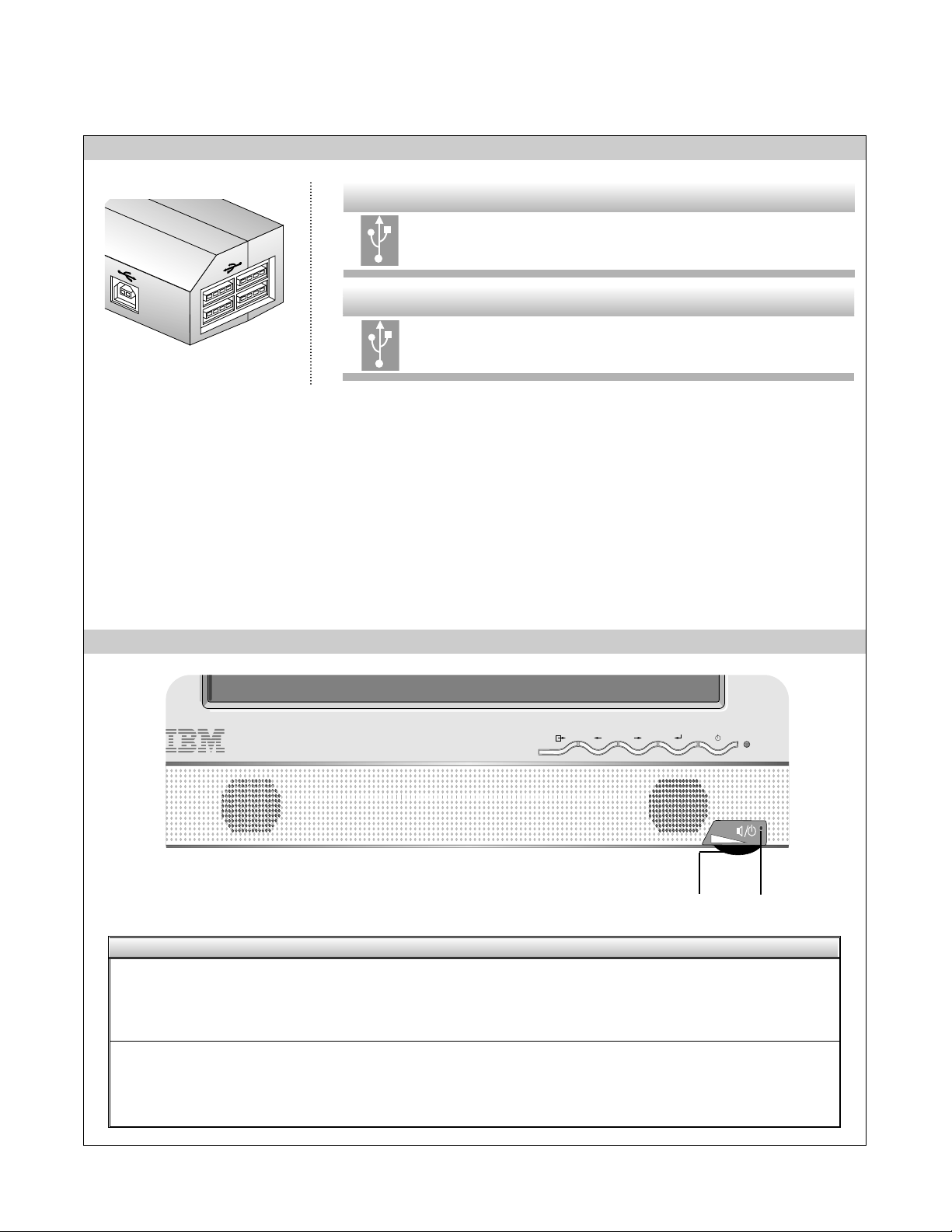
USB HUB Jacks External USB 1.1 low power devices such as
keyboards and mouse can be connected to these
ports.
Side Jacks
USB Devices Jack Connects the USB HUB to the computer system
Downstream port.
Rear Jack
Universal Serial Bus (USB) is an innovation that conveniently connects different devices to your computer. USB enables you to
have the flexibility to connect your mouse, keyboard, and other devides to the monitor instead of the computer. The
Speaker/USB HUB Option provides a 4 port USB HUB that will enabel you to connect a chain of up to 120 devices on a single
USB connection. You can “hot-plug” USB devices, that is, you can attach the devices while the computer is on. You can also
disconnect USB devices while maintaining “Plug and Play” auto detection and configuration. This monitor comes with an
integrated BUS-power USB HUB that can have up to four other USB devices attached to it. The Speaker/USB HUB Option has
an integrated BUS-powered HUB that meets the USB 2.0 Specification for Full Speed Devides, allowing up to 4 low power (<100
mA each) USB devices to be attached.
Front Control Panel
1. Power ON/OFF and Volume Control
Use to turn on/off audio and used to adjust
volume.
The light-emitting diode (LED) is turned
on for the speaker power ON and is turned
off for the speaker power OFF.
2. Indicator
Control Function
2
1
USB Control Panel
Page 6

Using the USB (Universal Serial Bus) HUB Featuers
- 6 -
Connecting USB devices
1. Insert the USB cable into the square USB connector of the Speaker/USB HUB Option as shown is the diagram on the left.
Then, insert the other end of the USB cable into the rectangular USB connector on a USB-compliant computer or USB hub as
shown in the diagram on the right.
2. Insert the USB cable for USB-compliant devices into the rectangular USB connector in the monitor as shown in the diagram on
the right.
USB downstream Ports
connect the cables from USBcompliant peripherals-such as
keyboard, mouse, etc
To USB downstream
port of the USBcompliant computer or
another hub cable
This is a simplified representation
of the rear view.
This is a simplified representation
of the side view.
Notes :
To activate the USB hub function, the
Speaker/USB HUB Option
must be connected to a USB compliant computer (OS) or
another hub with the USB cable(enclosed).
When connecting the USB cable, check that the shape of the connector at the cable side matches the shape at the connecting
side.
High powered devices (such as stand alone scanners and camera’s etc.) can not be connected to the USB HUB ports. Self
powered devices (use an extermal AC adapter to meet the high power repuirement) can be connected to the USB HUB port.
The USB HUB is compliant to the USB 2.0 Specification and will support low speed and full speed devices (same as USB 1.1).
The HUB can not support high speed devices and will connect them as full speed devices.
Page 7
- 7 -
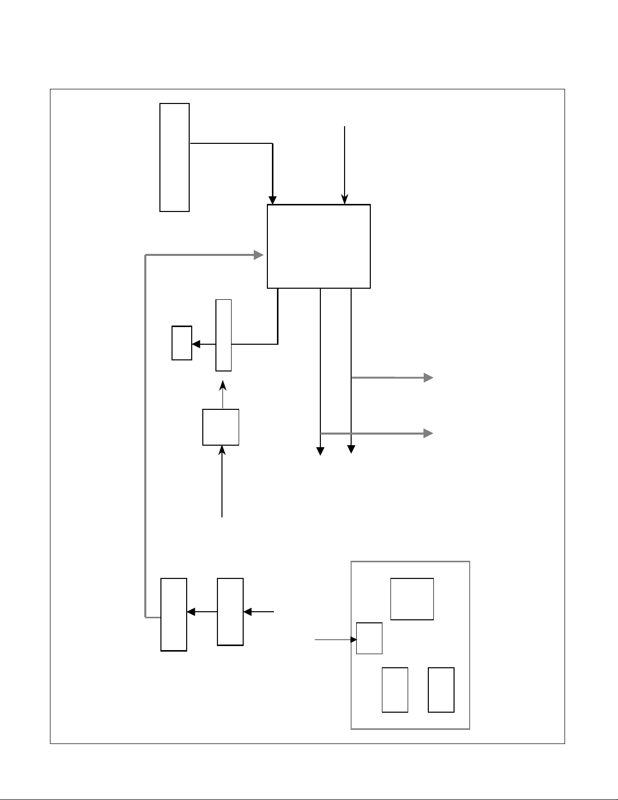
U/S
USB
HUB
5V
Reg.
Vari able Res istor
D/S*2
Bus-power USB
1 Up/4 Down
From Main 12V
Audio Amp
TDA7496L
Audio Input Signal
R/L : 700mVrms
DC Volume Control
Power On/Off
LED
Speaker R Out
Speaker L Out
Speaker R
Speaker L
Head Phone R Head Phone L
Mic In
PC
Mic Jack
From PC 5V
D/S*2
From Main 12V
BLOCK DIAGRAM
Page 8

- 8 -
DESCRIPTION OF BLOCK DIAGRAM
1. USB(Universal Serial Bus) Circuit
This circuit consists of USB hub IC(TUSB2046B), and over voltage protector IC(TPS2042ADR).
This circuit is used to expand four ports of down stream for your easy using of low power device such as
keyboard, mouse and etc.
The integrated Bus-Power USB HUB meets the USB 2.0 specification for Full Speed Devices, allowing
up to 4 low power USB devices to be attached.
2. Audio Circuit
This circuit supports speaker output of 1W+1W(Right, Left).
Main amp(TDA7496L) amplifies input audio signal and has function of volume control, and Shutdown
Volume On/Off/Up/Down Control varies the volume of sound going to the speakers and headphone jack,
and uses to turn on/off audio.
When headphone is plugged into the headphone jack, the speakers are muted, and Microphone input/output
pass through connection to system microphone input.
Page 9

TROUBLESHOOTING GUIDE
- 9 -
1. AUDIO NO POWER
POWER INDICATOR OFF
TROUBLE IN LED1
TROUBLE BUILT
IN POWER
NO
TROUBLE IN
VR1
TROUBLE
IN U5
NO NO
TROUBLE IN Q1, Q2
NO
YES
YES
YES
YES
CHECK
U5 OUTPUT
(5V) ?
CHECK
VR1?
CHECK
12V DC?
CHECK
Q1,Q2 ?
Page 10

- 10 -
2. NO VOLUME CONTROL
TROUBLE IN R3, R6, R9
NO
NO
TROUBLE IN VR1
TROUBLE IN U3
YES
YES
CHECK
VR1?
3. AUDIO NO OUTPUT
TROUBLE IN SPEAKER
TROUBLE IN U5
NO
YES
YES
CHECK
U3 OUTPUT
PIN 14, 17 ?
CHECK
U5
(5V)?
TROUBLE
IN U3
NO YES
CHECK
U3 PIN 4, 9
AUDIO IN?
CHECK
J4 AND PC?
TROUBLE
IN U3
NO YES
CHECK
U3 PIN 11, 12
(0V) ?
Page 11

- 11 -
4. USB NO OPERATING
TROUBLE IN
PC
TROUBLE IN
L102, L103
NO
NO
TROUBLE IN U101
NO
YES
YES
YES
CHECK
L102, L103
?
CHECK
J106 PIN1?
CHECK
U101 OUTPUT
(3.3V)?
TROUBLE IN X101
NO
YES
CHECK
X101?
TROUBLE IN U103
NO
YES
CHECK
U103?
Page 12

- 12 -
TROUBLE IN U110
NO
TROUBLE IN
J101, J104
TROUBLE IN
DEVICE
NO
YES
YES
CHECK
U110?
CHECK
J101, J104?
Page 13

PRINTED CIRCUIT BOARD
- 13 -
1. AUDIO BOARD
J2
R33
R32
C3
LED1
Q1
R4
R10 R11
Q2 R12
C4
R6
R7
R9
R13
R3
C2
VR1
J9
J3
J8
C24
R17
C25
R18
R15
C29
C18
L1
J7
C11
C38
U3
D3
C40
D6
R5
D2
C31
R30
R20D5
R14
C19
C32
R23
C30
R29
C9
C12
J4
C23
L2
J1
U5
C26
C8
C5
C37
C36
C6
C7
ZD2
L3
C1
R8
R1
MODEL:LI884E(AUDIO)
DATE :2002.04.18
P/N :6870T482S11
J5
Page 14

- 14 -
2. USB WAFER BOARD (Component Side)
ZD102
ZD101
J103
C117
C126
U101
ZD103
J106
C116
ZD109
ZD107
C122
ZD104
ZD106
ZD105
ZD110ZD108
J101
J104
3. USB WAFER BOARD (Solder Side)
R125
R126
R103
R102
R111
R108
R115
MODEL:SPT860(USB)
DATE :2002.04.16
P/N :6870T484U11
L103
C103
R106
R104
R101
R109
R110
R112
R107
R105
R113
R114
R116
L102
C101
C102
C109
C104
L104
L101
L108
L107
C110
C106
C105
L106
L105
L112
L113
C111
C113
Page 15

- 15 -
4. USB HUB BOARD (Component Side)
15
C120
L114
16
R124
C114
L115
C127
R119
D111
R129
U103
R120
C118
1
C121
2
J102
X101
5. USB HUB BOARD (Solder Side)
C115
U110
MODEL:SPT860(USB)
P/N :6870T483U11
C119
L118
R118
DATE :2002.04.16
Page 16

- 16 -
EXPLODED VIEW
1
8
7
11
2
6
5
4
a
b
9
10
3
Page 17

- 17 -
EXPLODED VIEW PARTS LIST
Ref. No.
1
2
3
4
5
6
7
8
9
10
11
a
b
Part No.
3550TKS059A
3550TKS059B
3550TKS060A
3550TKS060B
4940TKC018A
4940TKC018B
6871TST296A
6401TZZ027B
4950TKK337A
6871TUT019A
6852TAZ006L
6852TAZ006M
6852TAZ004K
6850TDU001A
1SZZTMT003A
1SZZTMT003B
332-113S
332-113N
Description
COVER, LI884E SPEAKER FRONT(S/BLACK) -(19K1901) Stealth Black
COVER, LI884E SPEAKER FRONT(P/WHITE) -(19K1902) Pearl White
COVER LI884E SPEAKER REAR(S/BLACK) -(19K1901) Stealth Black
COVER, LI884E SPEAKER REAR(P/WHITE) -(19K1902) Pearl White
KNOB, LI884E CONTROL VOLUME -(19K1901) Stealth Black
KNOB, LI884E CONTROL VOLUME -(19K1902) Pearl White
PWB(PCB) ASSEMBLY, SUB, LI884E SOUND TOTAL IBM CL-29 T860
SPEAKER ASSEMBLY, LI884E -18.1" LCD
METAL, FIX SPEAKER (LM568E)
PWB(PCB) ASSEMBLY, USB, LI884E SUB TOTAL IBM CL-29 T860
CORD, A/V, A/V KHC-ST-3-002 UL 2851 #28-2C 3000MM BLACK(9930)
CORD, A/V, A/V KHC-ST-3-0003 UL 2851 #28-2C 3000MM BLACK(9930
CORD, LINE, DC CABLE UNIXTAR 160 BLACK ANGLE TYPE,LI884E
CABLE, D-SUB, UL20276 #30 DT 3000MM BLACK(9930) LI884E GM
SCREW, DRAWING, D3.0 L10.0 MSWR/FZMCW1 LI884E -(19K1901) Stealth Black
SCREW, DRAWING, D3.0 L12.0 MSWR/FZMCW1 LI884E(P/W) -(19K1902) Pearl White
SCREW, DRAWING, D3.0 L12.0 MSWR/BK -(19K1901) Stealth Black
SCREW, PVP+3*12 MSWR/FZMW -(19K1902) Pearl White
Page 18

- 18 -
DATE: 2002. 04. 23.
*S *AL LOC. NO. PART NO. DESCRIPTION / SPECIFICATION
C101 0CC470CK41A 47PF 1608 50V 5% R/TP NP0
C104 0CC470CK41A 47PF 1608 50V 5% R/TP NP0
C105 0CC470CK41A 47PF 1608 50V 5% R/TP NP0
C106 0CC470CK41A 47PF 1608 50V 5% R/TP NP0
C109 0CC470CK41A 47PF 1608 50V 5% R/TP NP0
C110 0CC470CK41A 47PF 1608 50V 5% R/TP NP0
C111 0CC470CK41A 47PF 1608 50V 5% R/TP NP0
C113 0CC470CK41A 47PF 1608 50V 5% R/TP NP0
C114 0CK104CK56A 0.1UF 1608 50V 10% R/TP X7R
C115 0CK104CK56A 0.1UF 1608 50V 10% R/TP X7R
C116 0CH8107D611 100UF 10V M 85STD (CYL) R/TP
C117 0CH8107D611 100UF 10V M 85STD (CYL) R/TP
C118 0CC330CK41A 33PF 1608 50V 5% R/TP NP0
C119 0CK104CK56A 0.1UF 1608 50V 10% R/TP X7R
C120 0CH8107D611 100UF 10V M 85STD (CYL) R/TP
C121 0CC330CK41A 33PF 1608 50V 5% R/TP NP0
C122 0CK103CK51A 0.01UF 1608 50V 10% R/TP B(Y
C126 0CK103CK51A 0.01UF 1608 50V 10% R/TP B(Y
C127 0CH8105K611 1UF 50V M 85STD(CYL) R/TP
D111 0DS181009AA KDS181 TP KEC SOT-23 80V 3
ZD101 0DZ560009GB BZT52C5V6S DIODES R/TP SOD32
ZD102 0DZ560009GB BZT52C5V6S DIODES R/TP SOD32
ZD103 0DZ560009GB BZT52C5V6S DIODES R/TP SOD32
ZD104 0DZ560009GB BZT52C5V6S DIODES R/TP SOD32
ZD105 0DZ560009GB BZT52C5V6S DIODES R/TP SOD32
ZD106 0DZ560009GB BZT52C5V6S DIODES R/TP SOD32
ZD107 0DZ560009GB BZT52C5V6S DIODES R/TP SOD32
ZD108 0DZ560009GB BZT52C5V6S DIODES R/TP SOD32
ZD109 0DZ560009GB BZT52C5V6S DIODES R/TP SOD32
ZD110 0DZ560009GB BZT52C5V6S DIODES R/TP SOD32
U1 0ITI204200B TPS2042ADR TEXAS INSTRUMENT
U101 0IRH033200A BA033FP-E2 MOLD-3 TP REGULAT
U103 0ITI204600B TUSB2046B 32PQFP R/TP USB HU
L101 6210TCE001P HB-1S2012-121JT CERATECH 201
L102 6210TCE001P HB-1S2012-121JT CERATECH 201
L103 6210TCE001P HB-1S2012-121JT CERATECH 201
L104 6210TCE001P HB-1S2012-121JT CERATECH 201
L105 6210TCE001P HB-1S2012-121JT CERATECH 201
L106 6210TCE001P HB-1S2012-121JT CERATECH 201
L107 6210TCE001P HB-1S2012-121JT CERATECH 201
L108 6210TCE001P HB-1S2012-121JT CERATECH 201
L112 6210TCE001P HB-1S2012-121JT CERATECH 201
L113 6210TCE001P HB-1S2012-121JT CERATECH 201
DATE: 2002. 04. 23.
*S *AL LOC. NO. PART NO. DESCRIPTION / SPECIFICATION
L114 6210TCE001B HH-1H3216-500JT CERATEC 3216
L115 6210TCE001P HB-1S2012-121JT CERATECH 201
L118 6210TCE001P HB-1S2012-121JT CERATECH 201
R101 0RJ1502D677 15K OHM 1/10 W 5% 1608 R/TP
R102 0RJ0222D677 22 OHM 1/10 W 5% 1608 R/TP
R103 0RJ0222D677 22 OHM 1/10 W 5% 1608 R/TP
R104 0RJ1502D677 15K OHM 1/10 W 5% 1608 R/TP
R105 0RJ1502D677 15K OHM 1/10 W 5% 1608 R/TP
R106 0RJ0222D677 22 OHM 1/10 W 5% 1608 R/TP
R107 0RJ1502D677 15K OHM 1/10 W 5% 1608 R/TP
R108 0RJ0222D677 22 OHM 1/10 W 5% 1608 R/TP
R109 0RJ1502D677 15K OHM 1/10 W 5% 1608 R/TP
R110 0RJ0222D677 22 OHM 1/10 W 5% 1608 R/TP
R111 0RJ0222D677 22 OHM 1/10 W 5% 1608 R/TP
R112 0RJ1502D677 15K OHM 1/10 W 5% 1608 R/TP
R113 0RJ1502D677 15K OHM 1/10 W 5% 1608 R/TP
R114 0RJ0222D677 22 OHM 1/10 W 5% 1608 R/TP
R115 0RJ0222D677 22 OHM 1/10 W 5% 1608 R/TP
R116 0RJ1502D677 15K OHM 1/10 W 5% 1608 R/TP
R118 0RJ1501D677 1.5K OHM 1/10 W 5% 1608 R/TP
R119 0RJ1002D677 10K OHM 1/10 W 5% 1608 R/TP
R120 0RJ1501D677 1.5K OHM 1/10 W 5% 1608 R/TP
R124 0RJ1502D677 15K OHM 1/10 W 5% 1608 R/TP
R125 0RJ0222D677 22 OHM 1/10 W 5% 1608 R/TP
R126 0RJ0222D677 22 OHM 1/10 W 5% 1608 R/TP
R129 0RJ3602D677 36K OHM 1/10 W 5% 1608 R/TP
X101 6202TST001C SX-1, SUNNY SMD, 6.0MHZ ,50P
C1 0CE108EF618 1000UF KMG 16V M FL TP 5
C2 0CE107EF638 100UF KMG 16V M FM5 TP 5
C3 0CH8105K611 1UF 50V M 85STD(CYL) R/TP
C4 0CH8105K611 1UF 50V M 85STD(CYL) R/TP
C5 0CK104CK56A 0.1UF 1608 50V 10% R/TP X7R
C6 0CE107EF638 100UF KMG 16V M FM5 TP 5
C7 0CK103CK51A 0.01UF 1608 50V 10% R/TP B(Y
C8 0CK104CK56A 0.1UF 1608 50V 10% R/TP X7R
C9 0CH3105F946 1UF 16V Z F 2012 R/TP
C11 0CH3105F946 1UF 16V Z F 2012 R/TP
C12 0CH3105F946 1UF 16V Z F 2012 R/TP
C18 0CH3105F946 1UF 16V Z F 2012 R/TP
C19 0CH3105F946 1UF 16V Z F 2012 R/TP
C23 0CE477EF638 470UF KMG 16V M FM5 TP 5
C24 0CE477EF638 470UF KMG 16V M FM5 TP 5
C25 0CE477EF638 470UF KMG 16V M FM5 TP 5
C26 0CK103CK51A 0.01UF 1608 50V 10% R/TP B(Y
C29 0CH3105F946 1UF 16V Z F 2012 R/TP
REPLACEMENT PARTS LIST
CAUTION: BEFORE REPLACING ANY OF THESE COMPONENTS,
READ CAREFULLY THE SAFETY PRECAUTIONS IN THIS MANUAL.
* NOTE : S SAFETY Mark
AL ALTERNATIVE PARTS
USB BOARD
CAPACITORS
DIODEs
ICs
RESISTORs
COILs & COREs
SPEAKER BOARD
OTHERs
Page 19

DATE: 2002. 04. 23.
*S *AL LOC. NO. PART NO. DESCRIPTION / SPECIFICATION
C30 0CC121CK41A 120PF 1608 50V 5% R/TP NP0
C31 0CC121CK41A 120PF 1608 50V 5% R/TP NP0
C32 0CH3105F946 1UF 16V Z F 2012 R/TP
C36 0CK104CK56A 0.1UF 1608 50V 10% R/TP X7R
C37 0CK104CK56A 0.1UF 1608 50V 10% R/TP X7R
C38 0CH3105F946 1UF 16V Z F 2012 R/TP
C40 0CH3105F946 1UF 16V Z F 2012 R/TP
D2 0DS226009AA KDS226 TP KEC SOT-23 80V 30
D3 0DS226009AA KDS226 TP KEC SOT-23 80V 30
D5 0DS226009AA KDS226 TP KEC SOT-23 80V 30
D6 0DS226009AA KDS226 TP KEC SOT-23 80V 30
ZD2 0DZ560009GB BZT52C5V6S DIODES R/TP SOD32
Q1 0TR162309CA KSC1623 TP SAMSUNG SOT23 NP
Q2 0TR162309CA KSC1623 TP SAMSUNG SOT23 NP
R1 0RH0101D622 1.0 1/10W 5 TA
R3 0RJ5101D677 5.1K OHM 1/10 W 5% 1608 R/TP
R4 0RJ5602D477 56K OHM 1/10 W 1% 1608 R/TP
R5 0RJ1000D677 100 OHM 1/10 W 5% 1608 R/TP
R6 0RH3300D622 330 1/10W 5 D.R/TP
R7 0RJ1002D677 10K OHM 1/10 W 5% 1608 R/TP
R9 0RJ5101D677 5.1K OHM 1/10 W 5% 1608 R/TP
R10 0RJ3602D677 36K OHM 1/10 W 5% 1608 R/TP
R11 0RJ1502D677 15K OHM 1/10 W 5% 1608 R/TP
R12 0RH0000D622 0 1/10W P-TYPE TAPPING
R13 0RJ5602D477 56K OHM 1/10 W 1% 1608 R/TP
R14 0RJ1000D677 100 OHM 1/10 W 5% 1608 R/TP
R15 0RJ1000D677 100 OHM 1/10 W 5% 1608 R/TP
R17 0RJ0471D677 4.7 OHM 1/10 W 5% 1608 R/TP
R18 0RJ0471D677 4.7 OHM 1/10 W 5% 1608 R/TP
R20 0RJ3602D677 36K OHM 1/10 W 5% 1608 R/TP
R23 0RJ3602D677 36K OHM 1/10 W 5% 1608 R/TP
R29 0RJ1502D677 15K OHM 1/10 W 5% 1608 R/TP
R30 0RJ1502D677 15K OHM 1/10 W 5% 1608 R/TP
R32 0RH1200D622 120 1/10W 5 D.R/TP
R33 0RH1200D622 120 1/10W 5 D.R/TP
U3 0ISG749600A TDA7496L 20DIP BK 2W+2W AMP
U5 0ISS780500H KA78M05-R 3P,D-PAK TP 5V 0.5
J1 6612TAH003A DJ-023 KSD R/ANGLE LB563B
J2 6612F00006E KJA-PH-3-0032 KSD 3.5PHI 14P
J4 6612F00001D DJ-S360LM KSD STERO R/A LIME
J7 6612F00001A DJ-S360P KSD STEREO R/A PINK
L1 6210TCE001G HH-1M3216-501 CERATEC 3216MM
L2 150-985J DR10*12 2MH 0.28MM 220.5T R/
L3 6210TCE001Z HH-1M2012-600JT CERATEC R/TP
LED1 0DLLT0160AA LITEON LTL-4232NH63P BK GREE
VR1 6110R00001A RK0971111A14-10KB POSTEC 10K
- 19 -
Page 20

PIN CONFIGURATION
- 20 -
TDA7496L SGS-THOMOSN 2W+2W AMPLIFIER WITH DC VOLUME CONTROL
Powerdip(14+3+3)
ORDERING NUMBER: TDA7496L
GND
GND
GND
INL
VAROUT_L
VAROUT_R
VOLUME
N.C.
INR
1
3
2
4
5
6
7
8
9 MUTE
GND
OUTR
V
S
V
S
OUTL
GND
GND
GND20
19
18
17
16
14
15
13
12
D97AU597A
SVR 10 STBY11
PIN CONNECTION
VOLUME
OP AMP
+
-
MUTE/STBY
PROTECTIONS
9
470nF
INR
30K
VOLUME
OP AMP
+
-30K
1000mF
1000mF
1mF
10K
4
470nF
INL
7
14
11
12
17
65
300K
100nF
VOLUME
VAROUT_L
OUTR
STBY
MUTE
OUTL
1,2,3,13,
18,19,20
GND
470mF
SVR 10
D97AU596A
V
S
VAROUT_R
15,16
+5V
S1 ST-BY
+5V
S2 MUTE
+5V
S_GND
60K
BLOCK DIAGRAM
Pin Configuration
Page 21

SCHEMATIC DIAGRAM
- 21 -
1. AUDIO
Page 22

- 22 -
2. USB WAFER
Page 23

- 23 -
3. USB HUB
1
Page 24

Apr. 2002
Printed in Korea
P/NO : 3828TSO049B
 Loading...