

Page 1

BladeCenter HS22
Type 7870, 1936, and 1911
Problem Determination and Service Guide
Page 2

Page 3

BladeCenter HS22
Type 7870, 1936, and 1911
Problem Determination and Service Guide
Page 4

Note: Before using this information and the product it supports, read the general information in
“Notices” on page 239 and the Safety Information, Environmental Notices and User Guide, Warranty
Information documents on the IBM Documentation CD.
The most recent version of this document is available at http://www.ibm.com/systems/support/.
Fourteenth Edition (July 2011)
© Copyright IBM Corporation 2011.
US Government Users Restricted Rights – Use, duplication or disclosure restricted by GSA ADP Schedule Contract
with IBM Corp.
Page 5

Contents
Safety ...............v
Safety statements ............vi
Chapter 1. Start here .........1
Diagnosing a problem ...........1
Undocumented problems ..........5
Chapter 2. Introduction ........7
Related documentation ...........7
Notices and statements in this document .....8
Features and specifications..........9
Blade server controls and LEDs........11
Turning on the blade server .........14
Turning off the blade server .........14
Blade server system-board layouts.......15
Blade server connectors .........15
System-board switches..........16
System-board LEDs...........18
BladeCenter GPU expansion unit LED .....18
Chapter 3. Configuring the blade server 21
Using the Setup utility...........21
Setup utility menu ...........22
Using passwords ...........25
Using the Boot Menu program .......25
Updating the Universal Unique Identifier (UUID) 25
Updating the DMI/SMBIOS data ......28
Using the ServerGuide Setup and Installation CD . 31
ServerGuide features ..........32
Setup and configuration overview ......32
Installing the operating system .......33
Using the PXE boot agent utility program ....34
Firmware updates ............34
Configuring UEFI compatible devices .....35
Configuring the Gigabit Ethernet controller....35
Configuring a RAID array .........36
Using the LSI Logic Configuration Utility program 36
Using LAN over USB to interface the IMM ....37
Potential conflicts with the LAN over USB
interface ..............37
Resolving conflicts with the IMM LAN over USB
interface ..............37
Configuring the LAN over USB interface
manually ..............38
Chapter 4. Parts listing ........41
Parts listing, Type 7870, 1936, and 1911 .....41
Parts listing - BladeCenter GPU expansion unit . . 48
Chapter 5. Removing and replacing
blade server components.......49
Installation guidelines ...........49
System reliability guidelines ........50
Handling static-sensitive devices ......50
Returning a device or component ......51
Removing the blade server from the BladeCenter
unit .................52
Installing the blade server in a BladeCenter unit . . 53
Removing and replacing Tier 1 customer replaceable
units (CRUs) ..............55
Removing the blade server cover ......55
Closing the blade server cover .......56
Removing a blade handle.........57
Installing a blade handle .........58
Removing the battery ..........58
Installing the battery ..........60
Removing a hot-swap storage drive .....62
Installing a hot-swap storage drive .....63
Removing a memory module .......64
Installing a memory module........65
Removing a USB Flash key ........68
Installing a USB Flash key ........70
Removing an I/O expansion card ......71
Installing an I/O expansion card ......75
Removing and replacing Tier 2 CRUs......80
Removing the bezel assembly .......80
Installing the bezel assembly .......81
Removing the control panel ........82
Installing the control panel ........83
Removing and replacing field replaceable units
(FRUs) ................84
Removing an optional expansion unit ....84
Installing an optional expansion unit .....85
Removing a GPU adapter from the BladeCenter
GPU expansion unit ..........86
Installing a GPU adapter in the BladeCenter GPU
expansion unit ............88
Removing a microprocessor and heat sink . . . 90
Installing a microprocessor and heat sink . . . 94
Thermal grease ............96
Removing the system-board assembly ....97
Installing the system-board assembly .....98
Chapter 6. Diagnostics .......101
Diagnostic tools overview .........101
POST ................102
Error logs .............103
IMM error messages ..........105
POST error codes ...........146
Checkout procedure ...........165
About the checkout procedure.......165
Performing the checkout procedure .....165
Troubleshooting tables ..........166
General problems ...........166
Storage drive problems .........167
Intermittent problems .........167
Keyboard or mouse problems .......168
Memory problems ...........169
Monitor or video problems ........170
© Copyright IBM Corp. 2011 iii
Page 6

Network connection problems .......171
Optional-device problems ........172
Power error messages .........173
Power problems ...........176
Removable-media drive problems .....179
ServerGuide problems .........180
Software problems...........180
Universal Serial Bus (USB) port problems . . . 182
Light path diagnostics ..........183
Viewing the light path diagnostics LEDs in the
blade server .............183
Blade server light path diagnostics LEDs . . . 185
Viewing the light path diagnostics LEDs in the
BladeCenter GPU expansion unit ......187
BladeCenter GPU expansion unit light path
diagnostics LEDs ...........188
Dynamic system analysis diagnostic programs and
messages ...............189
Running the diagnostic programs .....190
Diagnostic text messages ........191
Viewing the test log ..........192
Diagnostic messages ..........192
IMM self tests .............193
Broadcom Ethernet device tests .......205
CPU stress tests ............206
Memory self tests ............209
Optical drive self tests ..........216
Storage drive self tests ..........222
Tape alert flags .............222
Recovering from a UEFI update failure .....223
In-band manual recovery method .....223
Out-of-band manual recovery method ....225
In-band automated boot recovery method . . . 226
Out-of-band automated boot recovery method 226
Service processor (IMM) error codes ......227
Solving SAS hard disk drive problems .....227
Solving shared BladeCenter resource problems . . 227
Keyboard or mouse problems .......228
Media tray problems ..........228
Network connection problems .......229
Power problems ...........230
Video problems............231
Solving undetermined problems .......232
Problem determination tips.........233
Appendix. Getting help and technical
assistance.............235
Before you call .............235
Using the documentation .........236
Getting help and information from the World Wide
Web................236
Software service and support ........236
Hardware service and support .......236
IBM Taiwan product service ........237
Notices ..............239
Trademarks ..............239
Important notes ............240
Particulate contamination .........241
Documentation format ..........242
Electronic emission notices .........242
Federal Communications Commission (FCC)
statement..............242
Industry Canada Class A emission compliance
statement..............242
Avis de conformité à la réglementation
d'Industrie Canada ..........242
Australia and New Zealand Class A statement 243
European Union EMC Directive conformance
statement..............243
Germany Class A statement .......243
Japan VCCI Class A statement.......244
Japan Electronics and Information Technology
Industries Association (JEITA) statement . . . 244
Korea Communications Commission (KCC)
statement..............245
Russia Electromagnetic Interference (EMI) Class
A statement .............245
People's Republic of China Class A electronic
emission statement ..........245
Taiwan Class A compliance statement ....245
Index ...............247
iv
BladeCenter HS22 Type 7870, 1936, and 1911: Problem Determination and Service Guide
Page 7
Safety
Before installing this product, read the Safety Information.
Antes de instalar este produto, leia as Informações de Segurança.
Pred instalací tohoto produktu si prectete prírucku bezpecnostních instrukcí.
Læs sikkerhedsforskrifterne, før du installerer dette produkt.
Lees voordat u dit product installeert eerst de veiligheidsvoorschriften.
Ennen kuin asennat tämän tuotteen, lue turvaohjeet kohdasta Safety Information.
Avant d'installer ce produit, lisez les consignes de sécurité.
Vor der Installation dieses Produkts die Sicherheitshinweise lesen.
Prima di installare questo prodotto, leggere le Informazioni sulla Sicurezza.
© Copyright IBM Corp. 2011 v
Page 8
Les sikkerhetsinformasjonen (Safety Information) før du installerer dette produktet.
Antes de instalar este produto, leia as Informações sobre Segurança.
Antes de instalar este producto, lea la información de seguridad.
Läs säkerhetsinformationen innan du installerar den här produkten.
Safety statements
These statements provide the caution and danger information that is used in this
documentation.
Important:
Each caution and danger statement in this documentation is labeled with a
number. This number is used to cross reference an English-language caution or
danger statement with translated versions of the caution or danger statement in
the Safety Information document.
For example, if a caution statement is labeled “Statement 1,” translations for that
caution statement are in the Safety Information document under “Statement 1.”
Be sure to read all caution and danger statements in this documentation before you
perform the procedures. Read any additional safety information that comes with
your system or optional device before you install the device.
Statement 1
vi BladeCenter HS22 Type 7870, 1936, and 1911: Problem Determination and Service Guide
Page 9

DANGER
Electrical current from power, telephone, and communication cables is
hazardous.
To avoid a shock hazard:
v Do not connect or disconnect any cables or perform installation,
maintenance, or reconfiguration of this product during an electrical storm.
v Connect all power cords to a properly wired and grounded electrical outlet.
v Connect to properly wired outlets any equipment that will be attached to
this product.
v When possible, use one hand only to connect or disconnect signal cables.
v Never turn on any equipment when there is evidence of fire, water, or
structural damage.
v Disconnect the attached power cords, telecommunications systems,
networks, and modems before you open the device covers, unless
instructed otherwise in the installation and configuration procedures.
v Connect and disconnect cables as described in the following table when
installing, moving, or opening covers on this product or attached devices.
To Connect: To Disconnect:
1. Turn everything OFF.
2. First, attach all cables to devices.
3. Attach signal cables to connectors.
4. Attach power cords to outlet.
5. Turn device ON.
1. Turn everything OFF.
2. First, remove power cords from outlet.
3. Remove signal cables from connectors.
4. Remove all cables from devices.
Statement 2
CAUTION:
When replacing the lithium battery, use only IBM®Part Number 33F8354 or an
equivalent type battery recommended by the manufacturer. If your system has a
module containing a lithium battery, replace it only with the same module type
made by the same manufacturer. The battery contains lithium and can explode if
not properly used, handled, or disposed of.
Do not:
v Throw or immerse into water
v Heat to more than 100°C (212°F)
v Repair or disassemble
Dispose of the battery as required by local ordinances or regulations.
Safety vii
Page 10
Statement 3
CAUTION:
When laser products (such as CD-ROMs, DVD drives, fiber optic devices, or
transmitters) are installed, note the following:
v Do not remove the covers. Removing the covers of the laser product could
result in exposure to hazardous laser radiation. There are no serviceable parts
inside the device.
v Use of controls or adjustments or performance of procedures other than those
specified herein might result in hazardous radiation exposure.
DANGER
Some laser products contain an embedded Class 3A or Class 3B laser diode.
Note the following.
Laser radiation when open. Do not stare into the beam, do not view directly
with optical instruments, and avoid direct exposure to the beam.
Class 1 Laser Product
Laser Klasse 1
Laser Klass 1
Luokan 1 Laserlaite
Appareil A Laser de Classe 1
`
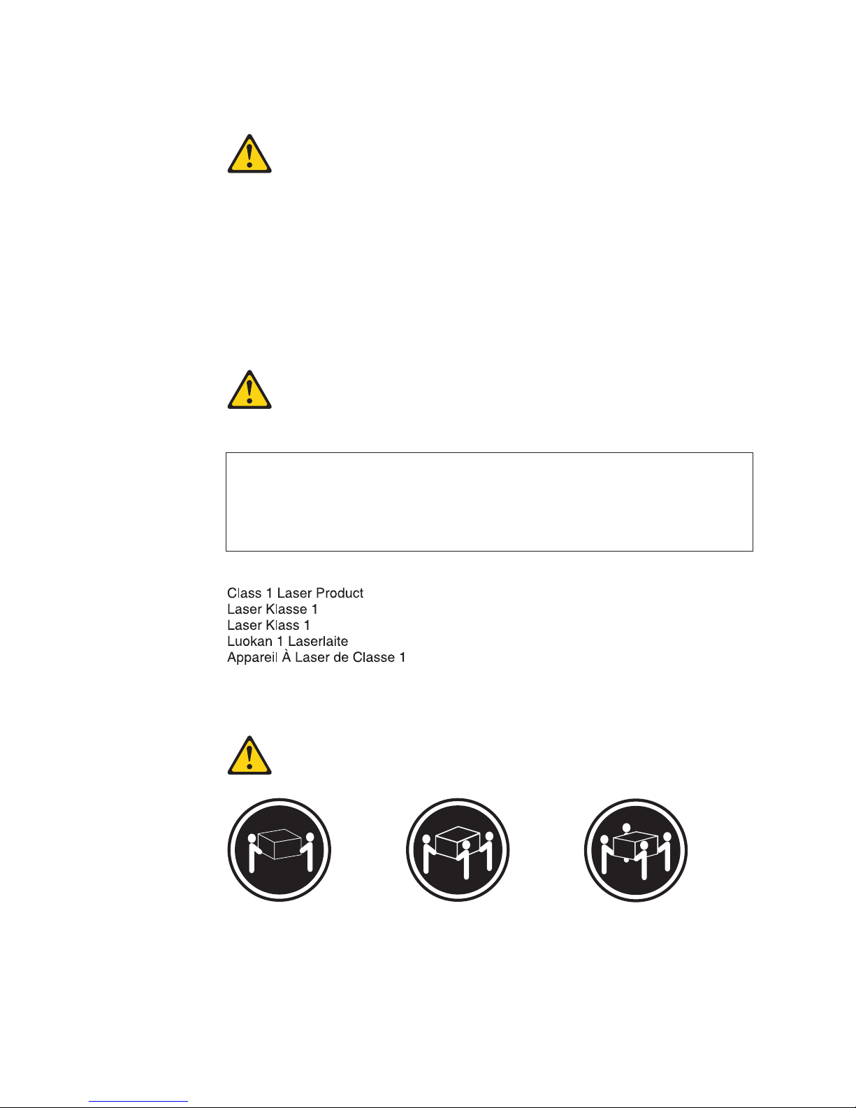
Statement 4
≥ 18 kg (39.7 lb) ≥ 32 kg (70.5 lb) ≥ 55 kg (121.2 lb)
CAUTION:
Use safe practices when lifting.
viii BladeCenter HS22 Type 7870, 1936, and 1911: Problem Determination and Service Guide
Page 11
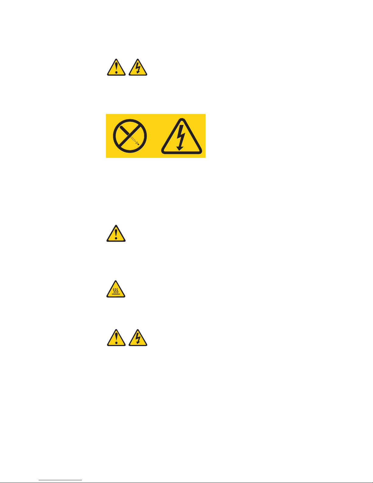
Statement 8
CAUTION:
Never remove the cover on a power supply or any part that has the following
label attached.
Hazardous voltage, current, and energy levels are present inside any component
that has this label attached. There are no serviceable parts inside these
components. If you suspect a problem with one of these parts, contact a service
technician.
Statement 12
CAUTION:
The following label indicates a hot surface nearby.
Statement 13
Safety ix
Page 12

DANGER
Overloading a branch circuit is potentially a fire hazard and a shock hazard
under certain conditions. To avoid these hazards, ensure that your system
electrical requirements do not exceed branch circuit protection requirements.
Refer to the information that is provided with your device for electrical
specifications.
Statement 21
CAUTION:
Hazardous energy is present when the blade is connected to the power source.
Always replace the blade cover before installing the blade.
Statement 32
CAUTION:
To avoid personal injury, before lifting the unit, remove all the blades, power
supplies, and removable modules to reduce the weight.
108 kg
(237 lbs)
(2X)
(6X)
(4X)
(4X)
43.2 kg
(95 lbs)
Statement 33
CAUTION:
This device does not provide a power control button. Removing power supply
modules or turning off the server blades does not turn off the electrical current
supplied to the device. The device also might have more than one power cord.
To remove all electrical current from the device, ensure that all power cords are
disconnected from the power source.
x BladeCenter HS22 Type 7870, 1936, and 1911: Problem Determination and Service Guide
Page 13
Rack Safety Information, Statement 2
DANGER
v Always lower the leveling pads on the rack cabinet.
v Always install stabilizer brackets on the rack cabinet.
v Always install servers and optional devices starting from the bottom of the
rack cabinet.
v Always install the heaviest devices in the bottom of the rack cabinet.
United Kingdom telecommunications safety requirement
Notice to Customers
This apparatus is approved under approval number NS/G/1234/J/100003 for
indirect connection to public telecommunication systems in the United Kingdom.
Safety xi
Page 14

xii BladeCenter HS22 Type 7870, 1936, and 1911: Problem Determination and Service Guide
Page 15

Chapter 1. Start here
You can solve many problems without outside assistance by following the
troubleshooting procedures in this documentation and on the IBM Web site.
This Problem Determination and Service Guide describes the diagnostic tests that you
can perform, troubleshooting procedures, and explanations of error messages and
error codes. The documentation that comes with your operating system and
software also contains troubleshooting information.
Diagnosing a problem
Before you contact IBM or an approved warranty service provider, follow these
procedures in the order in which they are presented to diagnose a problem with
your blade server.
1. Determine what has changed. Determine whether any of the following items
were added, removed, replaced, or updated before the problem occurred:
v Unified Extensible Firmware Interface (UEFI) code
v Device drivers
v Firmware
v Hardware components
v Software
If possible, return the blade server to the condition it was in before the problem
occurred.
2. Collect data. Thorough data collection is necessary for diagnosing hardware
and software problems.
Note: Event messages that include links to descriptions and recommended
actions can be viewed in the advanced management module event log (see the
Advanced Management Module User's Guide for additional information). A listing
of all general event information is in the BladeCenter Advanced Management
Module Messages Guide.
a. Document error codes and light path diagnostics LEDs.
v System error codes: See “Error logs” on page 103 for information about a
specific error code.
v Software or operating-system error codes: See the documentation for the
software or operating system for information about a specific error code.
See the manufacturer's Web site for documentation.
v Light path diagnostics LEDs: See “Light path diagnostics” on page 183
for information about LEDs that are lit.
© Copyright IBM Corp. 2011 1
Page 16

b. Collect system data. Run Dynamic System Analysis (DSA) to collect
information about the hardware, firmware, software, and operating system.
Have this information available when you contact IBM or an approved
warranty service provider. To download the latest version of DSA, go to
http://www.ibm.com/systems/support/supportsite.wss/
docdisplay?brandind=5000008&lndocid=SERV-DSA or complete the
following steps.
Note: Changes are made periodically to the IBM Web site. The actual
procedure might vary slightly from what is described in this document.
1) Go to http://www.ibm.com/systems/support/.
2) Under Product support, click BladeCenter.
3) Under Popular links, click Software and device drivers.
4) Under Related downloads, click Dynamic System Analysis (DSA).
For information about DSA command-line options, go to
http://publib.boulder.ibm.com/infocenter/toolsctr/v1r0/index.jsp?topic=/
dsa/dsa_main.html or complete the following steps:
1) Go to http://publib.boulder.ibm.com/infocenter/toolsctr/v1r0/
index.jsp.
2) In the navigation pane, click IBM System x and BladeCenter Tools
Center.
3) Click Tools reference → Error reporting and analysis tools → IBM
Dynamic System Analysis.
c. Collect BladeCenter unit data. Data about the BladeCenter unit is available
through the Advanced-Management-Module Web interface. Have this
information available when you contact IBM or an approved warranty
service provider. You can view the information or save it as a compressed
package, named Service Data, that you can transfer to another system or
provide to a service representative.
For information about saving the Service Data file, see the
Advanced-Management-Module User's Guide at IBM BladeCenter Advanced
Management Module: User's Guide or complete the following steps.
Note: Changes are made periodically to the IBM Web site. The actual
procedure might vary slightly from what is described in this document.
1) Go to http://www.ibm.com/systems/support/.
2) Under Product support, click BladeCenter.
3) Under Popular links, click Publications lookup.
4) From the Product family list, select any BladeCenter chassis and click
5) Under Documentation, click Advanced Management
2 BladeCenter HS22 Type 7870, 1936, and 1911: Problem Determination and Service Guide
Go.
Module/Management Module User's Guide - IBM BladeCenter E, H, T,
HT, S.
Page 17

3. Follow the problem-resolution procedures.
The four problem-resolution procedures are presented in the order in which
they are most likely to solve your problem. Follow these procedures in the
order in which they are presented:
a. Check for and apply code updates.
Most problems that appear to be caused by faulty hardware are actually
caused by UEFI code, system firmware, device firmware, or device drivers
that are not at the latest levels.
1) Determine the existing code levels.
v In DSA, click Firmware/VPD to view system firmware levels, or click
Software to view operating-system levels.
v In the navigation pane of the Advanced-Management-Module Web
interface, click Monitors and click Firmware VPD to view the
firmware levels in the blade servers and management module.
2) Download and install updates of code that is not at the latest level.
To display a list of available updates for your blade server, go to
http://www.ibm.com/systems/support/supportsite.wss/
docdisplay?brandind=5000008&lndocid=MIGR-63017 or complete the
following steps.
Note: Changes are made periodically to the IBM Web site. The actual
procedure might vary slightly from what is described in this document.
a) Go to http://www.ibm.com/systems/support/.
b) Under Product support, click BladeCenter.
c) Under Popular links, click Software and device drivers.
d) Click BladeCenter HS22to display the list of downloadable files for
the blade server.
You can install code updates that are packaged as an IBM UpdateXpress
System Pack or UpdateXpress CD image. An UpdateXpress System Pack
contains an integration-tested bundle of online firmware and
device-driver updates for your blade server.
Be sure to install any listed critical updates that have release dates that
are later than the release date of the UpdateXpress System Pack or
UpdateXpress image.
When you click an update, an information page is displayed, including
a list of the problems that the update fixes. Review this list for your
specific problem; however, even if your problem is not listed, installing
the update might solve the problem.
4. Check for and correct an incorrect configuration.
If the blade server is incorrectly configured, a system function can fail to work
when you enable it; if you make an incorrect change to the blade server
configuration, a system function that has been enabled can stop working.
a. Make sure that all installed hardware and software are supported.
See http://www.ibm.com/servers/eserver/serverproven/compat/us/
eserver.html to verify that the blade server supports the installed operating
system, optional devices, and software levels. If any hardware or software
component is not supported, uninstall it to determine whether it is causing
the problem. You must remove nonsupported hardware before you contact
IBM or an approved warranty service provider for support.
b. Make sure that the blade server, operating system, and software are
installed and configured correctly.
Chapter 1. Start here 3
Page 18

Many configuration problems are caused by loose power or signal cables or
incorrectly seated adapters. You might be able to solve the problem by
turning off the blade server, reconnecting cables, reseating adapters, and
turning the blade server back on.
If the problem is associated with a specific function (for example, if a RAID
hard disk drive is marked offline in the RAID array), see the documentation
for the associated controller and management or controlling software to
verify that the controller is correctly configured.
Problem determination information is available for many devices such as
RAID and network adapters.
For problems with operating systems or IBM software or devices, complete
the following steps.
Note: Changes are made periodically to the IBM Web site. The actual
procedure might vary slightly from what is described in this document.
1) Go to http://www.ibm.com/systems/support/.
2) Under Product support, click BladeCenter.
3) From the Product family list, select BladeCenter HS22.
4) Under Support & downloads, click Documentation, Install, and Use to
search for related documentation.
5. Check for service bulletins.
IBM service bulletins document known problems and suggested solutions. To
search for service bulletins, complete the following steps.
Note: Changes are made periodically to the IBM Web site. The actual
procedure might vary slightly from what is described in this document.
a. Go to http://www.ibm.com/systems/support/.
b. Under Product support, click BladeCenter.
c. From the Product family list, select BladeCenter HS22.
d. Under Support & downloads, click Troubleshoot.
6. Check for and replace defective hardware.
If a hardware component is not operating within specifications, it can cause
unpredictable results. Most hardware failures are reported as error codes in a
system or operating-system log. Hardware errors are also indicated by light
path diagnostics LEDs.
Troubleshooting procedures are provided on the IBM Web site. A single
problem might cause multiple symptoms. Follow the diagnostic procedure for
the most obvious symptom. If that procedure does not diagnose the problem,
use the procedure for another symptom, if possible. To locate troubleshooting
procedures for your server, complete the following steps.
Note: Changes are made periodically to the IBM Web site. The actual
procedure might vary slightly from what is described in this document.
a. Go to http://www.ibm.com/systems/support/.
b. Under Product support, click BladeCenter.
c. From the Product family list, select BladeCenter HS22.
d. Under Support & downloads, click Troubleshoot.
e. Under Diagnostic, select the troubleshooting procedure for the symptom
that you are observing.
4 BladeCenter HS22 Type 7870, 1936, and 1911: Problem Determination and Service Guide
Page 19

If the problem remains, contact IBM or an approved warranty service provider
for assistance with additional problem determination and possible hardware
replacement. To open an online service request, go to http://www.ibm.com/
support/electronic/portal/. Be prepared to provide information about any
error codes and collected data.
Undocumented problems
If you have completed the diagnostic procedure and the problem remains, the
problem might not have been previously identified by IBM. After you have
verified that all code is at the latest level, all hardware and software configurations
are valid, and no light path diagnostics LEDs or log entries indicate a hardware
component failure, contact IBM or an approved warranty service provider for
assistance.
To open an online service request, go to http://www.ibm.com/support/electronic/
portal/. Be prepared to provide information about any error codes and collected
data and the problem determination procedures that you have used.
Chapter 1. Start here 5
Page 20

6 BladeCenter HS22 Type 7870, 1936, and 1911: Problem Determination and Service Guide
Page 21

Chapter 2. Introduction
Use this information to help you solve problems that might occur in your blade
server.
This Problem Determination and Service Guide contains information to help you solve
problems that might occur in your IBM BladeCenter
blade server. It describes the diagnostic tools that come with the blade server, error
codes and suggested actions, and instructions for replacing failing components.
Replaceable components are of three types:
v Tier 1 customer replaceable unit (CRU): Replacement of Tier 1 CRUs is your
responsibility. If IBM installs a Tier 1 CRU at your request, you will be charged
for the installation.
v Tier 2 CRU: You may install a Tier 2 CRU yourself or request IBM to install it, at
no additional charge, under the type of warranty service that is designated for
your server.
v Field replaceable unit (FRU): FRUs must be installed only by trained service
technicians.
For information about the terms of the warranty and getting service and assistance,
see the Warranty and Support Information document on the IBM Documentation CD.
Related documentation
Use this information to identify and locate related blade server documentation.
This Problem Determination and Service Guide document is in Portable Document
Format (PDF) on the IBM Documentation CD. It contains information to help you
solve problems yourself, and it contains information for service technicians:
v Installation and User's Guide
The Installation and User's Guide contains general information about the blade
server, including how to install supported optional devices and how to configure
the blade server. The following documentation also comes with the blade server.
v Safety Information
This document is in PDF on the IBM Documentation CD. It contains translated
caution and danger statements. Each caution and danger statement that appears
in the documentation has a number that you can use to locate the corresponding
statement in your language in the Safety Information document.
v Warranty and Support Information
This document is in PDF on the IBM Documentation CD. It contains information
about the terms of the warranty and getting service and assistance.
v Environmental Notices and User Guide
This document is in PDF on the IBM Documentation CD. It contains translated
environmental notices.
v Integrated Management Module User's Guide
®
HS22 Type 7870 and 1936
© Copyright IBM Corp. 2011 7
Page 22

This document is in PDF on the IBM Web site. This document explains how to
use the functions of the IMM installed in an IBM server. The IMM works with
IBM System x Server Firmware to provide systems-management capability for
System x and BladeCenter servers.
v Advanced Management Module Messages Guide
This document is in PDF on the IBM Web site at http://www.ibm.com/
systems/support/. This document provides a complete list of all non-device
specific events and recommended actions, sorted by event ID. Device specific
event information is in the documentation for the device.
v BladeCenter GPU Expansion Blade Installation Guide
This document is in PDF on the IBM Web site at http://www.ibm.com/
systems/support/. This document includes information about the BladeCenter
GPU expansion unit, including instructions for installing options and
troubleshooting problems in the expansion unit.
Depending on your BladeCenter product, additional documents might be included
on the IBM Documentation CD. In addition to the documentation in this library, be
sure to review the Planning and Installation Guide for your BladeCenter unit for
information to help you prepare for system installation and configuration. To check
for updated documentation and technical updates, complete the following steps.
Note: Changes are made periodically to the IBM Web site. The actual procedure
might vary slightly from what is described in this document.
1. Go to http://www.ibm.com/systems/support/.
2. Under Product support, click BladeCenter.
3. Under Popular links, click Publications lookup.
4. From the Product family menu, select BladeCenter HS22 and click Continue.
Notices and statements in this document
Use this information to understand the most common documentation notices and
statements and how they are used.
The caution and danger statements in this document are also in the multilingual
Safety Information document, which is on the IBM Documentation CD. Each
statement is numbered for reference to the corresponding statement in the Safety
Information document.
The following notices and statements are used in this document:
v Note: These notices provide important tips, guidance, or advice.
v Important: These notices provide information or advice that might help you
avoid inconvenient or problem situations.
v Attention: These notices indicate possible damage to programs, devices, or data.
An attention notice is placed just before the instruction or situation in which
damage might occur.
v Caution: These statements indicate situations that can be potentially hazardous
to you. A caution statement is placed just before the description of a potentially
hazardous procedure step or situation.
v Danger: These statements indicate situations that can be potentially lethal or
extremely hazardous to you. A danger statement is placed just before the
description of a potentially lethal or extremely hazardous procedure step or
situation.
8 BladeCenter HS22 Type 7870, 1936, and 1911: Problem Determination and Service Guide
Page 23

Features and specifications
Use this table to view specific information about the blade server, such as blade
server hardware features and the dimensions of the blade server.
Notes:
1. Power, cooling, removable-media drives, external ports, and advanced system
management are provided by the BladeCenter unit.
2. The operating system in the blade server must provide USB support for the
blade server to recognize and use USB media drives and devices. The
BladeCenter unit uses USB for internal communications with these devices.
Chapter 2. Introduction 9
Page 24

The following table is a summary of the features and specifications of the blade
server.
Table 1. Features and specifications
Microprocessor: Supports up to two
multi-core Intel Xeon microprocessors.
Note: Use the Setup utility to
determine the type and speed of the
microprocessors in the blade server.
Memory:
v 12 dual inline memory module
(DIMM) connectors
v Type: Very Low Profile (VLP)
double-data rate (DDR3) DRAM.
Supports 1 GB, 2 GB, 4 GB, 8 GB,
and 16 GB DIMMs with up to 192
GB of total memory on the system
board
Integrated functions:
v Horizontal-compact-form-factor
(CFFh) expansion card interface
v Vertical-combination-I/O (CIOv)
expansion card interface
v Local service processor: Integrated
Management Module (IMM) with
Intelligent Platform Management
Interface (IPMI) firmware
v Integrated Matrox G200eV video
controller
v LSI 1064E SAS controller
v Broadcom BCM5709S dual-port
Gigabit Ethernet controller
v Integrated keyboard/video/mouse
(cKVM) controller through IMM
v Light path diagnostics
v RS-485 interface for communication
with the management module
v Automatic server restart (ASR)
v USB 2.0 for communication with
cKVM and removable media drives
(an external USB port is not
supported)
v Serial over LAN (SOL)
v Redundant buses for
communication with keyboard,
mouse, and removable media
drives
Predictive Failure Analysis (PFA)
alerts:
v Microprocessors
v Memory
v Storage drives
Electrical input: 12Vdc
Environment:
v Air temperature:
– Blade server on: 10°C to 35°C
(50°F to 95°F). Altitude:0mto
914.4 m (0 ft to 3000 ft)
– Blade server on: 10°C to 32°C
(50°F to 89.6°F). Altitude: 914.4
m to 2133.6 m (3000 ft to 7000
ft)
– Blade server off: 10°C to 43°C
(50°F to 109.4°F). Altitude: 914.4
m to 2133.6 m (3000 ft to 7000
ft)
– Blade server shipping: -40°C to
60°C (-40°F to 140°F)
v Humidity:
– Blade server on: 8% to 80%
– Blade server off: 8% to 80%
– Blade server storage: 5% to 80%
– Blade server shipment: 5% to
100%
v Particulate contamination:
Attention: Airborne particulates
and reactive gases acting alone or
in combination with other
environmental factors such as
humidity or temperature might
pose a risk to the server. For
information about the limits for
particulates and gases, see
“Particulate contamination” on
page 241.
Drives: Supports up to two hot-swap,
small form factor (SFF) Serial Attached
SCSI (SAS) or Serial ATA (SATA)
storage drives
Size (Type 7870 and Type 1936):
v Height: 24.5 cm (9.7 inches) (6U)
v Depth: 44.6 cm (17.6 inches)
v Width: 2.9 cm (1.14 inches)
v Maximum weight: 4.8 kg (10 lb)
Size (Type 1911):
v Height: 24.5 cm (9.7 in)
v Depth: 44.6 cm (17.6 in)
v Width: 14.5 cm (5.71 in)
v Maximum weight: 8.15 kg (40.02 lb)
NEBS Environment
v Air temperature:
– Blade server on: 5°C to 40°C (41°F
to 104°F). Altitude: -60 m to 1800
m (-197 ft to 6000 ft)
– Blade server on: 5°C to 30°C (41°F
to 86°F). Altitude: 1800 m to 4000
m (6000 ft to 13000 ft)
– Blade server off: -5°C to 55°C
(23°F to 131°F). Altitude: -60 m to
1800 m (-197 ft to 6000 ft)
– Blade server off: -5°C to 45°C
(23°F to 113°F). Altitude: 1800 m
to 4000 m (6000 ft to 13000 ft)
– Blade server storage: -40°C to
60°C (-40°F to 140°F)
v Humidity: 8% to 85%
v Particulate contamination:
Attention: Airborne particulates
and reactive gases acting alone or in
combination with other
environmental factors such as
humidity or temperature might pose
a risk to the server. For information
about the limits for particulates and
gases, see “Particulate
contamination” on page 241.
10 BladeCenter HS22 Type 7870, 1936, and 1911: Problem Determination and Service Guide
Page 25
Blade server controls and LEDs
Use this information for details about the controls and LEDs on the blade server.
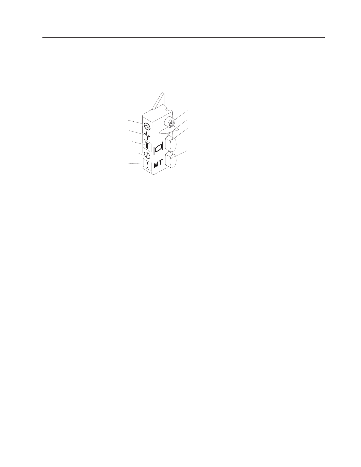
The following illustration identifies the buttons and information LEDs on the
blade-server control panel.
Power LED
Activity LED
Location LED
Information LED
Fault LED
Power-on LED: This green LED indicates the power status of the blade server in
the following manner:
v Flashing rapidly: While the service processor in the blade server is initializing
and synchronizing with the management module, the power-on LED flashes
rapidly, and the power-control button on the blade server does not respond. This
process can take approximately two minutes after the blade server has been
installed. If the LED continues to flash rapidly, the blade server might not have
power permissions assigned to it through the Advanced Management Module,
the BladeCenter unit does not have enough power to turn on the blade server,
or the service processor (IMM) on the blade server is not communicating with
the Advanced Management Module.
v Flashing slowly: The blade server has power supplied and is ready to be turned
on.
v Lit continuously: The blade server has power and is turned on.
Powe r
button
NMI button
KVM select
button/LED
Media-tray select
button/LED
Activity LED: When this green LED is lit, it indicates that there is activity on the
external storage device or network.
Location LED: The system administrator can remotely turn on this blue LED to aid
in visually locating the blade server. When this LED is lit, the location LED on the
BladeCenter unit is also lit. The location LED can be turned off through the
Advanced-Management-Module Web interface or through IBM
For more information about the Advanced-Management-Module Web interface, see
http://www.ibm.com/systems/management/. For more information about IBM
Director, see the documentation on the IBM®Director CD that comes with the
server, or visit the IBM®Director Information Center at http://
publib.boulder.ibm.com/infocenter/director/v6r1x/index.jsp.
Information LED: When this amber LED is lit, it indicates that information about a
system event in the blade server has been placed in the Advanced-ManagementModule event log. The information LED can be turned off through the
Advanced-Management-Module CLI, SNMP, or Web interface or through IBM
Director Console. For more information about the Advanced-Management-Module
Web interface, see http://www.ibm.com/systems/management/. For more
®
Director Console.
®
®
Chapter 2. Introduction 11
Page 26

information about IBM®Director, see the documentation on the IBM®Director CD
that comes with the server, or visit the IBM®Director Information Center at
http://publib.boulder.ibm.com/infocenter/director/v6r1x/index.jsp.
Fault LED: When this amber LED is lit, it indicates that a system error has
occurred in the blade server. The blade-error LED turns off only after the error is
corrected.
Power-control button: Press this button to turn on or turn off the blade server.
Note: The power-control button has effect only if local power control is enabled
for the blade server. Local power control is enabled and disabled through the
Advanced-Management-Module Web interface.
NMI button (recessed): The nonmaskable interrupt (NMI) dumps the partition.
Use this recessed button only as directed by IBM Support.
Note: You can also send an NMI event to the selected blade server remotely using
the AMM. For more information, see the BladeCenter Advanced Management Module
User's Guide.
Keyboard/video/mouse (KVM) select button: Press this button to associate the
shared BladeCenter unit keyboard port, video port, and mouse port with the blade
server. The LED on this button flashes while the request is being processed and
then is lit when the ownership of the keyboard, video, and mouse has been
transferred to the blade server. It can take approximately 20 seconds to switch the
keyboard, video, and mouse control to the blade server.
Using a keyboard that is directly attached to the Advanced-Management-Module,
you can press keyboard keys in the following sequence to switch KVM control
between blade servers instead of using the KVM select button:
NumLock NumLock blade_server_number Enter
blade_server_number is the two-digit number of the blade-server bay in which
the blade server is installed. A blade server that occupies more than one
blade-server bay is identified by the lowest bay number that it occupies.
If there is no response when you press the KVM select button, you can use the
Advanced-Management-Module Web interface to determine whether local control
has been disabled on the blade server. See http://www.ibm.com/systems/
management/ for more information.
Notes:
1. The operating system in the blade server must provide USB support for the
blade server to recognize and use the keyboard and mouse, even if the
keyboard and mouse have PS/2-style connectors.
2. If you install a supported Microsoft Windows operating system on the blade
server while it is not the current owner of the keyboard, video, and mouse, a
delay of up to 1 minute occurs the first time that you switch the keyboard,
video, and mouse to the blade server. All subsequent switching takes place in
the normal KVM switching time frame (up to 20 seconds).
Media-tray select button: Press this button to associate the shared BladeCenter
unit media tray (removable-media drives) with the blade server. The LED on the
button flashes while the request is being processed and then is lit when the
12 BladeCenter HS22 Type 7870, 1936, and 1911: Problem Determination and Service Guide
Page 27
ownership of the media tray has been transferred to the blade server. It can take
approximately 20 seconds for the operating system in the blade server to recognize
the media tray.
If there is no response when you press the media-tray select button, you can use
the Advanced-Management-Module Web interface to determine whether local
control has been disabled on the blade server.
Note: The operating system in the blade server must provide USB support for the
blade server to recognize and use the removable-media drives.
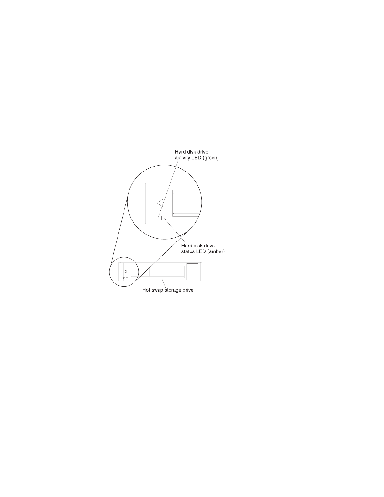
The following illustration identifies the information LEDs on the SAS hot-swap
hard disk drive.
Hard disk drive activity LED (green): When this green LED is lit, it indicates that
there is activity on the storage drive.
Hard disk drive status LED (amber): When this amber LED is lit, it indicates that
an error has occurred with the storage drive. The LED turns off only after the error
is corrected.
Chapter 2. Introduction 13
Page 28

Turning on the blade server
Use this information to turn on the blade server.
After you connect the blade server to power through the BladeCenter unit, the
blade server can start in any of the following ways:
v You can press the power-control button on the front of the blade server (see
“Blade server controls and LEDs” on page 11) to start the blade server.
Notes:
1. Wait until the power-on LED on the blade server flashes slowly before you
press the power-control button. While the service processor in the blade
server is initializing and synchronizing with the management module, the
power-on LED flashes rapidly, and the power-control button on the blade
server does not respond. This process can take approximately two minutes
after the blade server has been installed.
2. While the blade server is starting, the power-on LED on the front of the
blade server is lit and does not flash. See “Blade server controls and LEDs”
on page 11 for the power-on LED states.
v If a power failure occurs, the BladeCenter unit and the blade server can be
configured to start automatically when power is restored through the Advanced
Management Module.
v You can turn on the blade server remotely by using the management module.
v If the blade server is connected to power (the power-on LED is flashing slowly),
the blade server is communicating with the management module, the operating
system supports the Wake on LAN feature, and the Wake on LAN feature has
not been disabled through the management module, the Wake on LAN feature
can turn on the blade server.
Turning off the blade server
Use this information to turn off the blade server.
When you turn off the blade server, it is still connected to power through the
BladeCenter unit. The blade server can respond to requests from the service
processor, such as a remote request to turn on the blade server. To remove all
power from the blade server, you must remove it from the BladeCenter unit. Shut
down the operating system before you turn off the blade server. See the
operating-system documentation for information about shutting down the
operating system.
The blade server can be turned off in any of the following ways:
v You can press the power-control button on the blade server (see “Blade server
controls and LEDs” on page 11). This starts an orderly shutdown of the
operating system, if this feature is supported by the operating system.
v If the operating system stops functioning, you can press and hold the
power-control button for more than 4 seconds to turn off the blade server.
v The management module can turn off the blade server through the
Advanced-Management-Module Web interface. For additional information, see
the IBM BladeCenter Management Module User’s Guide or go to
http://www-03.ibm.com/systems/management/ for more information.
14 BladeCenter HS22 Type 7870, 1936, and 1911: Problem Determination and Service Guide
Page 29
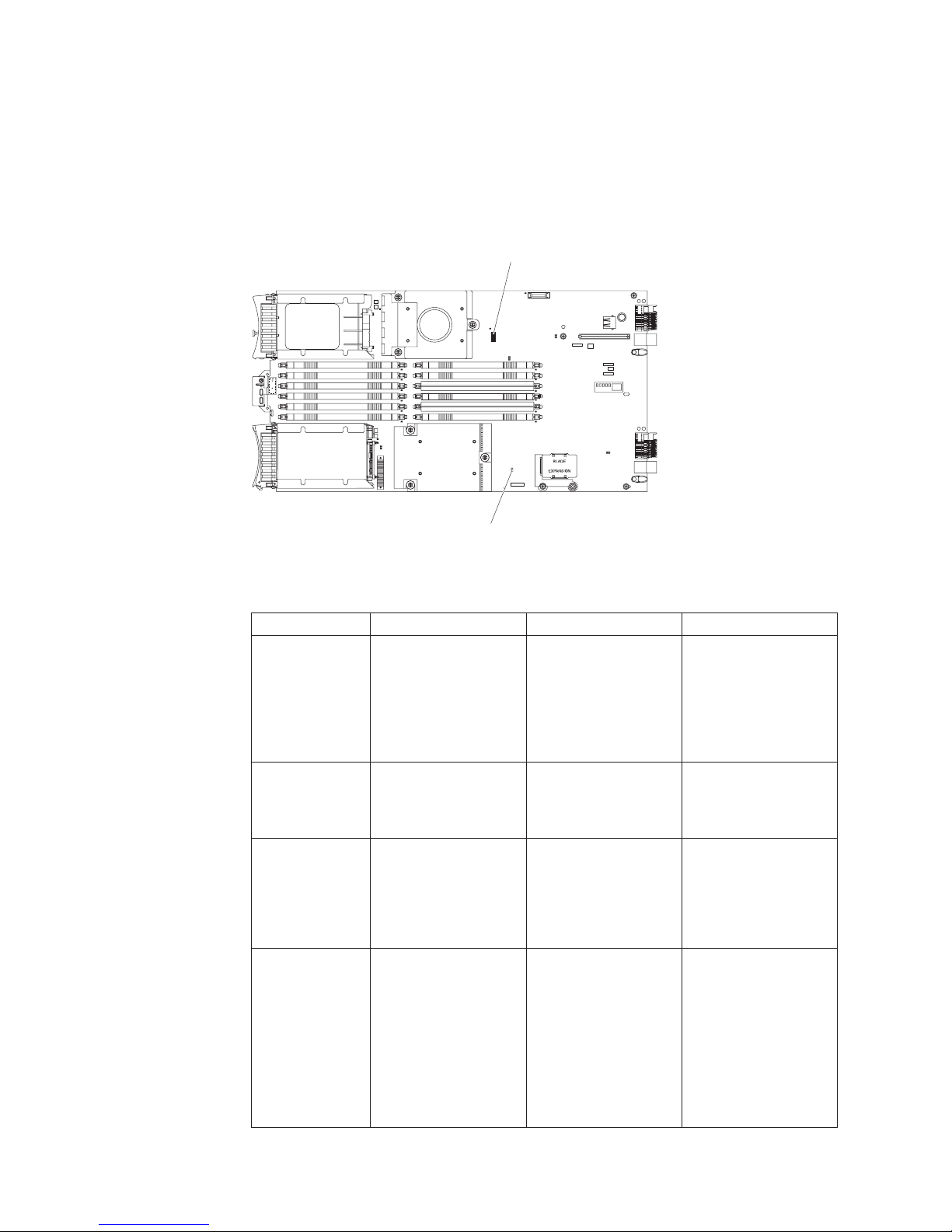
Blade server system-board layouts
Use this layout to locate connectors, LEDs and switches on the system board of the
blade server.
The following illustrations show the connectors, LEDs, and switches on the system
board. The illustrations in this document might differ slightly from your hardware.
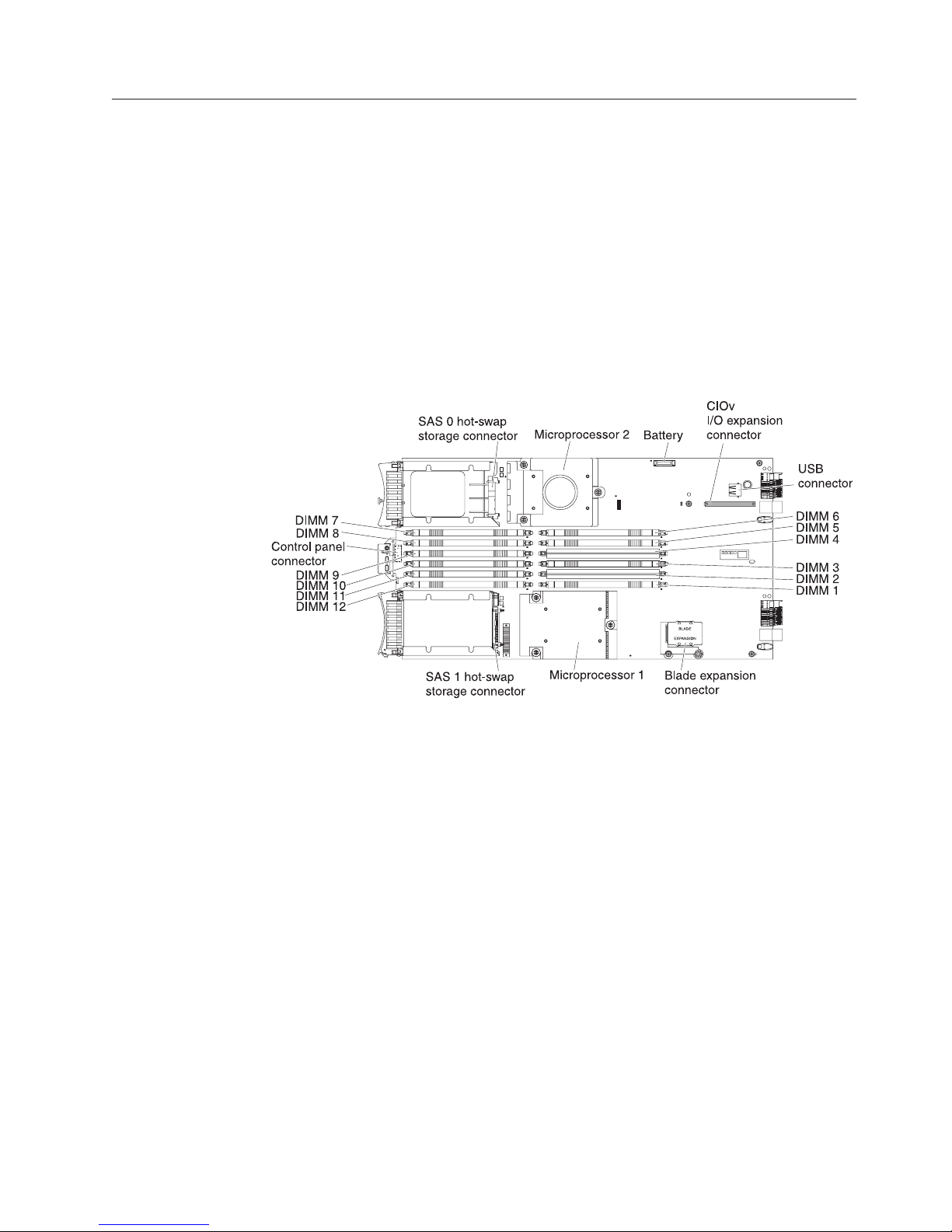
Blade server connectors
Use this information to locate blade server system-board components and
connectors for optional devices.
The following illustration shows the system-board components, including
connectors for user-installable optional devices, in the blade server.
Chapter 2. Introduction 15
Page 30
System-board switches
Use this information to locate and define system-board switches in the blade
server.
The following illustration shows the location of the light path diagnostics switch
on the system board.
SW1
SW3
The following table describes the function of each switch in the switch blocks
(SW1, SW2, SW3).
Switch number Description Switch setting Definition
SW1 - 1 Password override
switch
SW1 - 2 Trusted Platform
Module (TPM)
physical presence
SW1 - 3 ICH9 RTC reset Normally open. Toggle
SW1 - 4 Boot using the backup
IMM code.
Changing position of
this switch resets the
power on password.
The default position is
off.
to reset RTC.
The default position is
off, allowing the blade
server to boot from the
primary IMM
firmware.
This switch overrides
the power on
password. The system
ships with this switch
off, but it can be on or
off in a functioning
system.
Turning this switch to
the on position
indicates a physical
presence to the TPM.
Resets the RTC. A
momentary toggle is
all that is required. To
avoid excessive battery
drain, do not leave this
switch closed.
When the switch is in
the default off
position, the blade
server will boot using
the primary IMM
firmware. When the
switch is on, the blade
server will boot using
a backup of the IMM
firmware.
16 BladeCenter HS22 Type 7870, 1936, and 1911: Problem Determination and Service Guide
Page 31

Switch number Description Switch setting Definition
SW1 - 5 Boot block recovery The default position is
off, allowing the blade
server to boot from the
primary UEFI
When the switch is on
it allows the blade
server to boot using
the backup UEFI.
firmware.
SW1 - 6 IMM force update The default position is
off.
SW1 - 7 Wake on LAN (WOL)
disable
The default position is
off.
For trained service
technician only.
Turning this switch to
the on position
disables WOL.
SW1 - 8 Force H8 update The default position is
N/A
off.
SW3 Light path diagnostics
switch
The default position is
off. Turning this switch
on lights the light path
diagnostic LEDs.
Push down on the
light path diagnostics
switch push button to
light the diagnostic
LEDs.
Chapter 2. Introduction 17
Page 32

System-board LEDs
Use this information to locate system-board LEDs in the blade server.
You must remove the blade server from the BladeCenter unit, open the cover or
remove any optional expansion units, and press the light path diagnostics switch
(see “System-board switches” on page 16) to light any error LEDs that were turned
on during processing. Diagnosing problems using the light path diagnostic LEDs is
described in “Light path diagnostics” on page 183.
The following illustration shows the light path diagnostics panel on the system
board.
System board error LED
SYS BRD
NMI
TEMP
MIS
LP 1
Light Path
diagnostic switch
The following illustration shows the LEDs on the system board.
NMI error LED
Over Temperature LED
Microprocessor
mismatch LED
Light Path
diagnostic LED
SAS 0error LED
DIMM 7error LED
DIMM 8error LED
DIMM 9error LED
DIMM 10error LED
DIMM 11error LED
DIMM 12error LED
SAS 1error LED
BladeCenter GPU expansion unit LED
The following illustration identifies the fault LED on the front of the BladeCenter
GPU expansion (BGE) unit.
Microprocessor 2error LED
Microprocessor 1error LED
Fault LED
Batteryerror LED
DIMM 6error LED
DIMM 5error LED
DIMM 4error LED
DIMM 3error LED
DIMM 2error LED
DIMM 1error LED
18 BladeCenter HS22 Type 7870, 1936, and 1911: Problem Determination and Service Guide
!
Page 33

Fault LED: When this amber LED is lit, it indicates that an error has occurred in
the expansion blade. The expansion blade error LED turns off only after the error
is corrected.
If an error occurs in the expansion blade, the fault LED on the blade device on
which the expansion blade is installed is also lit. Additional information about the
error is provided by the light-path LEDs in the expansion blade (see “BladeCenter
GPU expansion unit light path diagnostics LEDs” on page 188 for more
information).
Chapter 2. Introduction 19
Page 34

20 BladeCenter HS22 Type 7870, 1936, and 1911: Problem Determination and Service Guide
Page 35

Chapter 3. Configuring the blade server
Use this information for details about the configuration requirements of the blade
server.
This chapter describes the configuration requirements of the blade server. Before
you continue, make sure that the blade server has the latest version of firmware
code. For additional information, see “Firmware updates” on page 34.
The following configuration programs come with the blade server:
v Setup utility
The Setup utility is used to change system settings, such as interrupt requests
(IRQ), date and time, and password. See “Using the Setup utility” for more
information.
v LSI Logic Configuration Utility program
The LSI Logic Configuration Utility program is stored in the blade-server
firmware. Use it to set the device scan order and to set the storage drive
controller IDs. See “Using the LSI Logic Configuration Utility program” on page
36 for more information.
v IBM ServerGuide Setup and Installation CD
The ServerGuide program provides software-setup tools and installation tools
that are designed for the blade server. Use this CD during the installation of the
blade server to configure basic hardware features and to simplify the installation
of the operating system. For information about obtaining and using this CD, see
“Using the ServerGuide Setup and Installation CD” on page 31.
v Preboot Execution Environment (PXE) boot agent utility program
The PXE boot agent utility program is part of the blade server firmware. Use it
to select the boot protocol and other boot options and to select a
power-management option. For information about using this utility program, see
“Using the PXE boot agent utility program” on page 34.
The IBM Remote Deployment Manager (RDM) Version 4.4 program is available for
purchase. You can use RDM to install a UEFI code update onto a blade server. For
the latest information about RDM, including which operating systems that RDM
supports and how to purchase the software, see http://www.ibm.com/systems/
management/.
Using the Setup utility
Use these instructions to start the Setup utility.
To start the Setup utility, complete the following steps:
1. Turn on the blade server (see “Turning on the blade server” on page 14).
2. Immediately give the blade server control of the BladeCenter unit shared
keyboard, video, and mouse ports.
v If you are managing the blade server by using the BladeCenter system
console, press the KVM select button on the blade server (see “Blade server
controls and LEDs” on page 11 for information).
v If you are managing the blade server from a remote location, see the IBM
BladeCenter Management Module User's Guide, IBM BladeCenter Management
© Copyright IBM Corp. 2011 21
Page 36

Module Command-Line Interface Reference Guide,orIBM BladeCenter Serial over
LAN Setup Guide for information and instructions.
3. When the prompt <F1> Setup is displayed, press F1. If you have set an
administrator password, you must type the administrator password to access
the full Setup-utility menu. If you do not type the administrator password, a
limited Setup-utility menu is available.
4. Follow the instructions on the screen.
Setup utility menu
Use the Setup utility main menu to view and configure blade server configuration
data and settings.
The following menu items are on the Setup utility main menu. Depending on the
version of the Unified Extensible Firmware Interface (UEFI), some menu items
might differ slightly from these descriptions.
v System Information
Select this choice to view information about the server. When you make changes
through other choices in the Setup utility, some of those changes are reflected in
the system information; you cannot change settings directly in the system
information. This choice is on the full Setup utility menu only.
– System Summary
Select this choice to view configuration information, including the ID, speed,
and cache size of the microprocessors, machine type and model of the server,
the serial number, the system UUID, and the amount of installed memory.
When you make configuration changes through other options in the Setup
utility, the changes are reflected in the system summary; you cannot change
settings directly in the system summary.
– Product Data
Select this choice to view the system-board identifier, the revision level or
issue date of the firmware, the integrated management module and
diagnostics code, and the version and date.
This choice is on the full UEFI Setup Utility menu only.
v System Settings
Select this choice to view or change the server component settings.
– Processors
Select this choice to view or change the processor settings.
– Memory
Select this choice to view or change the memory settings.
– Devices and I/O Ports
Select this choice to view or change assignments for devices and
input/output (I/O) ports. You can configure the remote console redirection,
enable or disable integrated Ethernet controllers, and the SAS controller. If
you disable a device, it cannot be configured, and the operating system will
not be able to detect it (this is equivalent to disconnecting the device).
– Power
Select this choice to view or change power capping to control power
consumption and processor performance states.
22 BladeCenter HS22 Type 7870, 1936, and 1911: Problem Determination and Service Guide
Page 37

– Legacy Support
Select this choice to view or set legacy support.
- Force Legacy Video on Boot
Select this choice to force INT video support, if the operating system does
not support UEFI video output standards.
- Rehook INT
Select this choice to enable or disable devices from taking control of the
boot process. The default is Disable.
- Legacy Thunk Support
Select this choice to enable or disable UEFI to interact with PCI mass
storage devices that are non-UEFI compliant.
– Integrated Management Module
Select this choice to view or change the settings for the integrated
management module.
- POST Watchdog Timer
Select this choice to view or enable the POST watchdog timer.
- POST Watchdog Timer Value
Select this choice to view or set the POST loader watchdog timer value.
- Reboot System on NMI
Enable or disable restarting the system whenever a nonmaskable interrupt
(NMI) occurs. Disabled is the default.
- Network Configuration
Select this choice to view the system management network interface port,
the IMM MAC address, the current IMM IP address, and host name; define
the static IMM IP address, subnet mask, and gateway address, specify
whether to use the static IP address or have DHCP assign the IMM IP
address, save the network changes, and reset the IMM.
- Reset IMM to Defaults
Select this choice to view or reset IMM to the default settings.
– System Security
Select this choice to view or configure security options.
– Adapters and UEFI Drivers
Select this choice to view information about the adapters and UEFI drivers
installed in the server.
– Network
Select this choice to view or configure the network device options, such as
iSCSI, PXE, and Broadcom.
– Trusted Platform Module (TPM)
Select this choice to view and configure TPM settings.
v Date and Time
Select this choice to set the date and time in the server, in 24-hour format
(hour:minute:second).
This choice is on the full UEFI Setup Utility menu only.
v Start Options
Select this choice to view or change the start options, including the startup
sequence, keyboard NumLock state, PXE boot option, and PCI device boot
priority. Changes in the startup options take effect when you start the server.
Chapter 3. Configuring the blade server 23
Page 38

The startup sequence specifies the order in which the server checks devices to
find a boot record. The server starts from the first boot record that it finds. If the
server has Wake on LAN hardware and software and the operating system
supports Wake on LAN functions, you can specify a startup sequence for the
Wake on LAN functions. For example, you can define a startup sequence that
checks for a disc in the CD-RW/DVD drive, then checks the hard disk drive,
and then checks a network adapter.
This choice is on the full UEFI Setup Utility menu only.
v Boot Manager
Select this choice to view, add, delete, or change the device boot priority, boot
from a file, select a one-time boot, or reset the boot order to the default setting.
v System Event Logs
Select this choice to enter the System Event Manager, where you can view the
error messages in the system event logs. You can use the arrow keys to move
between pages in the error log.
The system event logs contain all event and error messages that have been
generated during POST, by the systems-management interface handler, and by
the system service processor. Run the diagnostic programs to get more
information about error codes that occur. See Chapter 6, “Diagnostics,” on page
101 for instructions on running the diagnostic programs.
Important: If the system-error LED on the front of the server is lit but there are
no other error indications, clear the IMM system-event log. Also, after you
complete a repair or correct an error, clear the IMM system-event log to turn off
the system-error LED on the front of the server.
– POST Event Viewer
Select this choice to enter the POST event viewer to view the POST error
messages.
– IMM System Event Log
Select this choice to view the IMM system event log.
– Clear IMM System Event Log
Select this choice to clear the IMM system event log.
v User Security
Select this choice to set, change, or clear passwords. See “Using passwords” on
page 25 for more information.
v Save Settings
Select this choice to save the changes that you have made in the settings.
v Restore Settings
Select this choice to cancel the changes that you have made in the settings and
restore the previous settings.
v Load Default Settings
Select this choice to cancel the changes that you have made in the settings and
restore the factory settings.
v Exit Setup
Select this choice to exit from the Setup utility. If you have not saved the
changes that you have made in the settings, you are asked whether you want to
save the changes or exit without saving them.
24 BladeCenter HS22 Type 7870, 1936, and 1911: Problem Determination and Service Guide
Page 39

Using passwords
Use this information to set, change, or delete a power-on password.
You can set, change, and delete a power-on password and an administrator
password in the Setup utility by selecting System Settings then System Security.
If you set a power-on password, you must type the power-on password to
complete the system startup and to have access to the Setup Utility menu.
The password must be from 6 to 20 characters. You can use any combination of
ASCII printable characters for the password. Keep a record of your password in a
secure place.
If you forget the power-on password, you can regain access to the blade server
either by removing the blade server battery and then reinstalling it or by using the
power-on password override switch (see “Removing the battery” on page 58 and
“Installing the battery” on page 60).
An administrator password is intended to be used by a system administrator; it
limits access to the full Setup utility menu.
Attention: If you set an administrator password and then forget it, there is no
way to change, override, or remove it. You must replace the system board.
Using the Boot Menu program
Use the Boot Menu program to temporarily redefine the first startup device
without changing settings in the Setup utility.
The Boot Menu program is a built-in, menu-driven configuration utility program
that you can use to temporarily redefine the first startup device without changing
settings in the Setup utility.
To use the Boot Menu program, complete the following steps:
1. Turn off the server.
2. Restart the server.
3. When the prompt <F12> Select Boot Device is displayed, press F12 . If a
bootable USB mass storage device is installed, a submenu item (USB Key/Disk)
is displayed.
4. Use the Up arrow and Down arrow keys to select an item from the Boot
Selection Menu and press Enter.
The next time the server starts, it returns to the startup sequence that is set in the
Setup utility.
Updating the Universal Unique Identifier (UUID)
The Universal Unique Identifier (UUID) must be updated when the system board
is replaced.
The Universal Unique Identifier (UUID) must be updated when the system board
is replaced. Use the Advanced Settings Utility to update the UUID in the
UEFI-based server. The ASU is an online tool that supports several operating
Chapter 3. Configuring the blade server 25
Page 40

systems. Make sure that you download the version for your operating system. You
can download the ASU from the IBM Web site. To download the ASU and update
the UUID, complete the following steps.
Note: Changes are made periodically to the IBM Web site. The actual procedure
might vary slightly from what is described in this document.
1. Download the Advanced Settings Utility (ASU):
a. Go to http://www.ibm.com/systems/support/.
b. Under Product support, select System x.
c. Under Popular links, select Tools and utilities.
d. Scroll down to Configuration; then, select Advanced Settings Utility (ASU).
e. In the next window under Download, click the Advanced Settings Utility
link and download the ASU version for your blade server.To view more
information about using the Advanced Settings Utility, scroll down to
Online Help; then, click User's Guide for the IBM Advanced Settings
Utility.
Note: To view more information about using the Advanced Settings Utility,
scroll down to Online Help; then, click User's Guide for the IBM Advanced
Settings Utility.
f. In the next window under File link, click the Advanced Settings Utility link
for your operating system to begin downloading the utility.
2. ASU sets the UUID in the Integrated Management Module (IMM). Select one of
the following methods to access the Integrated Management Module (IMM) to
set the UUID:
v Online from the target system (LAN or keyboard console style (KCS) access)
v Remote access to the target system (LAN based)
v Bootable media containing ASU (LAN or KCS, depending upon the bootable
media)
Note: IBM provides a method for building a bootable media. You can create
a bootable media using the Bootable Media Creator (BoMC) application from
the Tools Center Web site. In addition, the Windows and Linux based tool
kits are also available to build a bootable media. These tool kits provide an
alternate method to creating a Windows Professional Edition or Master
Control Program (MCP) based bootable media, which will include the ASU
application.
3. Copy and unpack the ASU package, which also includes other required files, to
the server. Make sure that you unpack the ASU and the required files to the
same directory. In addition to the application executable (asu or asu64), the
following files are required:
v For Windows based operating systems:
– ibm_rndis_server_os.inf
– device.cat
v For Linux based operating systems:
– cdc_interface.sh
4. After you install ASU, use the following command syntax to set the UUID:
asu set SYSTEM_PROD_DATA.SysInfoUUID <uuid_value> [access_method]
Where:
26 BladeCenter HS22 Type 7870, 1936, and 1911: Problem Determination and Service Guide
Page 41

<uuid_value>
Up to 16-byte hexadecimal value assigned by you.
[access_method]
The access method that you selected to use from the following
methods:
v Online authenticated LAN access, type the command:
[host <imm_internal_ip>] [user <imm_user_id>][password <imm_password>]
Where:
imm_internal_ip
The IMM internal LAN/USB IP address. The default value is
169.254.95.118.
imm_user_id
The IMM account (1 of 12 accounts). The default value is USERID.
imm_password
The IMM account password (1 of 12 accounts). The default value is
PASSW0RD (with a zero 0 not an O).
Note: If you do not specify any of these parameters, ASU will use the
default values. When the default values are used and ASU is unable to access
the IMM using the online authenticated LAN access method, ASU will
automatically use the unauthenticated KCS access method.
The following commands are examples of using the userid and password
default values and not using the default values:
Example that does not use the userid and password default values:
asu set SYSTEM_PROD_DATA.SYsInfoUUID <uuid_value> user <user_id>
password <password>
Example that does use the userid and password default values:
asu set SYSTEM_PROD_DATA.SysInfoUUID <uuid_value>
v Online KCS access (unauthenticated and user restricted):
You do not need to specify a value for access_method when you use this
access method.
Example:
asu set SYSTEM_PROD_DATA.SysInfoUUID <uuid_value>
The KCS access method uses the IPMI/KCS interface. This method requires
that the IPMI driver be installed. Some operating systems have the IPMI
driver installed by default. ASU provides the corresponding mapping layer.
See the Advanced Settings Utility Users Guide for more details. You can access
the ASU Users Guide from the IBM Web site.
Note: Changes are made periodically to the IBM Web site. The actual
procedure might vary slightly from what is described in this document.
a. Go to http://www.ibm.com/systems/support.
b. Under Product support, select System x.
c. Under Popular links, select Tools and utilities.
d. In the left pane, click System x and BladeCenter Tools Center.
e. Scroll down and click Tools reference.
f. Scroll down and click the plus-sign (+) for Configuration tools to expand
the list; then, select Advanced Settings Utility (ASU).
Chapter 3. Configuring the blade server 27
Page 42

g. In the next window under Related Information, click the Advanced
Settings Utility link.
v Remote LAN access, type the command:
Note: When using the remote LAN access method to access IMM using the
LAN from a client, the host and the imm_external_ip address are required
parameters.
host <imm_external_ip> [user <imm_user_id>[[password <imm_password>]
Where:
imm_external_ip
The external IMM LAN IP address. There is no default value. This
parameter is required.
imm_user_id
The IMM account (1 of 12 accounts). The default value is USERID.
imm_password
The IMM account password (1 of 12 accounts). The default value is
PASSW0RD (with a zero 0 not an O).
The following commands are examples of using the userid and password
default values and not using the default values:
Example that does not use the userid and password default values:
asu set SYSTEM_PROD_DATA.SYsInfoUUID <uuid_value> host <imm_ip>
user <user_id> password <password>
Example that does use the userid and password default values:
asu set SYSTEM_PROD_DATA.SysInfoUUID <uuid_value> host <imm_ip>
v Bootable media:
You can also build a bootable media using the applications available through
the Tools Center Web site at http://publib.boulder.ibm.com/infocenter/
toolsctr/v1r0/index.jsp. From the left pane, click IBM System x and
BladeCenter Tools Center, then click Tool reference for the available tools.
5. Restart the server.
Updating the DMI/SMBIOS data
The Desktop Management Interface (DMI) must be updated when the system
board is replaced.
The Desktop Management Interface (DMI) must be updated when the system
board is replaced. Use the Advanced Settings Utility to update the DMI in the
UEFI-based server. The ASU is an online tool that supports several operating
systems. Make sure that you download the version for your operating system. You
can download the ASU from the IBM Web site. To download the ASU and update
the DMI, complete the following steps.
Note: Changes are made periodically to the IBM Web site. The actual procedure
might vary slightly from what is described in this document.
1. Download the Advanced Settings Utility (ASU):
a. Go to http://www.ibm.com/systems/support/.
b. Under Product support, select System x.
c. Under Popular links, select Tools and utilities.
d. Scroll down to Configuration; then, select Advanced Settings Utility (ASU).
28 BladeCenter HS22 Type 7870, 1936, and 1911: Problem Determination and Service Guide
Page 43

e. In the next window under Download, click the Advanced Settings Utility
link and download the ASU version for your blade server.To view more
information about using the Advanced Settings Utility, scroll down to
Online Help; then, click User's Guide for the IBM Advanced Settings
Utility.
Note: To view more information about using the Advanced Settings Utility,
scroll down to Online Help; then, click User's Guide for the IBM Advanced
Settings Utility.
f. In the next window under File link, click the Advanced Settings Utility link
for your operating system to begin downloading the utility.
2. ASU sets the DMI in the Integrated Management Module (IMM). Select one of
the following methods to access the Integrated Management Module (IMM) to
set the DMI:
v Online from the target system (LAN or keyboard console style (KCS) access)
v Remote access to the target system (LAN based)
v Bootable media containing ASU (LAN or KCS, depending upon the bootable
media)
Note: IBM provides a method for building a bootable media. You can create
a bootable media using the Bootable Media Creator (BoMC) application from
the Tools Center Web site. In addition, the Windows and Linux based tool
kits are also available to build a bootable media. These tool kits provide an
alternate method to creating a Windows Professional Edition or Master
Control Program (MCP) based bootable media, which will include the ASU
application.
3. Copy and unpack the ASU package, which also includes other required files, to
the server. Make sure that you unpack the ASU and the required files to the
same directory. In addition to the application executable (asu or asu64), the
following files are required:
v For Windows based operating systems:
– ibm_rndis_server_os.inf
– device.cat
v For Linux based operating systems:
– cdc_interface.sh
4. After you install ASU, Type the following commands to set the DMI:
asu set SYSTEM_PROD_DATA.SysInfoProdName <m/t_model> [access_method]
asu set SYSTEM_PROD_DATA.SysInfoSerialNum <s/n> [access_method]
asu set SYSTEM_PROD_DATA.SysEncloseAssetTag <asset_tag>
[access_method]
Where:
<m/t_model>
<s/n> The serial number on the server. Type sn zzzzzzz, where zzzzzzz is the
<asset_method>
The server machine type and model number. Type mtm xxxxyyy, where
xxxx is the machine type and yyy is the server model number.
serial number.
The server asset tag number. Type asset
aaaaaaaaaaaaaaaaaaaaaaaaaaaaaaaaa, where
aaaaaaaaaaaaaaaaaaaaaaaaaaaaaaaaa is the asset tag number.
Chapter 3. Configuring the blade server 29
Page 44

[access_method]
The access method that you select to use from the following methods:
v Online authenticated LAN access, type the command:
[host <imm_internal_ip>] [user <imm_user_id>][password
<imm_password>]
Where:
imm_internal_ip
The IMM internal LAN/USB IP address. The default value is
169.254.95.118.
imm_user_id
The IMM account (1 of 12 accounts). The default value is USERID.
imm_password
The IMM account password (1 of 12 accounts). The default value is
PASSW0RD (with a zero 0 not an O).
Note: If you do not specify any of these parameters, ASU will use the
default values. When the default values are used and ASU is unable to access
the IMM using the online authenticated LAN access method, ASU will
automatically use the following unauthenticated KCS access method.
The following commands are examples of using the userid and password
default values and not using the default values:
Examples that do not use the userid and password default values:
asu set SYSTEM_PROD_DATA.SYsInfoProdName <m/t_model> --user
<imm_user_id> --password <imm_password>
asu set SYSTEM_PROD_DATA.SYsInfoSerialNum <s/n> --user <imm_user_id>
--password <imm_password>
asu set SYSTEM_PROD_DATA.SYsEncloseAssetTag <asset_tag> --user
<imm_user_id> --password <imm_password>
Examples that do use the userid and password default values:asu set
SYSTEM_PROD_DATA.SysInfoProdName <m/t_model> asu set
SYSTEM_PROD_DATA.SysInfoSerialNum <s/n> asu set
SYSTEM_PROD_DATA.SysEncloseAssetTag <asset_tag>
v Online KCS access (unauthenticated and user restricted):
You do not need to specify a value for access_method when you use this
access method.
The KCS access method uses the IPMI/KCS interface. This method requires
that the IPMI driver be installed. Some operating systems have the IPMI
driver installed by default. ASU provides the corresponding mapping layer.
See the Advanced Settings Utility Users Guide at http://www-947.ibm.com/
systems/support/supportsite.wss/docdisplay?brandind=5000008
&lndocid=MIGR-55021 for more details.
The following commands are examples of using the userid and password
default values and not using the default values:
Examples that do not use the userid and password default values:
asu set SYSTEM_PROD_DATA.SYsInfoProdName <m/t_model>
asu set SYSTEM_PROD_DATA.SYsInfoSerialNum <s/n>
asu set SYSTEM_PROD_DATA.SYsEncloseAssetTag <asset_tag>
30 BladeCenter HS22 Type 7870, 1936, and 1911: Problem Determination and Service Guide
Page 45

v Remote LAN access, type the command:
Note: When using the remote LAN access method to access IMM using the
LAN from a client, the host and the imm_external_ip address are required
parameters.
host <imm_external_ip> [user <imm_user_id>][password <imm_password>]
Where:
imm_external_ip
The external IMM LAN IP address. There is no default value. This
parameter is required.
imm_user_id
The IMM account (1 of 12 accounts). The default value is USERID.
imm_password
The IMM account password (1 of 12 accounts). The default value is
PASSW0RD (with a zero 0 not an O).
The following commands are examples of using the userid and password
default values and not using the default values:
Examples that do not use the userid and password default values:
asu set SYSTEM_PROD_DATA.SYsInfoProdName <m/t_model> --host <imm_ip>
--user <imm_user_id> --password <imm_password>
asu set SYSTEM_PROD_DATA.SYsInfoSerialNum <s/n> --host <imm_ip> --user
<imm_user_id> --password <imm_password>
asu set SYSTEM_PROD_DATA.SYsEncloseAssetTag <asset_tag> --host
<imm_ip> --user <imm_user_id> --password <imm_password>
Examples that do use the userid and password default values:
asu set SYSTEM_PROD_DATA.SysInfoProdName <m/t_model> --host <imm_ip>
asu set SYSTEM_PROD_DATA.SysInfoSerialNum <s/n> --host <imm_ip>
asu set SYSTEM_PROD_DATA.SysEncloseAssetTag <asset_tag> --host
<imm_ip>
v Bootable media:
You can also build a bootable media using the applications available through
the Tools Center Web site at http://publib.boulder.ibm.com/infocenter/
toolsctr/v1r0/index.jsp. From Deployment Tools, click Bootable Media
Creator.
5. Restart the server.
Using the ServerGuide Setup and Installation CD
Use this information as an overview for using the ServerGuide Setup and
Installation CD.
The ServerGuide Setup and Installation CD contains a setup and installation program
that is designed for your blade server. The ServerGuide program detects the blade
server model and optional hardware devices that are installed and uses that
information during setup to configure the hardware. The ServerGuide program
simplifies operating-system installations by providing updated device drivers and,
in some cases, installing them automatically.
You can download a free image of the ServerGuide Setup and Installation CD or
purchase the CD from the ServerGuide fulfillment Web site at
Chapter 3. Configuring the blade server 31
Page 46

http://www.ibm.com/systems/management/serverguide/sub.html. To download
the free image, click IBM Service and Support Site.
Note: Changes are made periodically to the IBM Web site. The actual procedure
might vary slightly from what is in this document.
The ServerGuide program performs the following tasks:
v An easy-to-use interface
v Diskette-free setup and configuration programs that are based on detected
hardware
v Device drivers that are provided for the blade server model and detected
hardware
v Operating-system partition size and file-system type that are selectable during
setup
ServerGuide features
Use this information to determine the ServerGuide features.
Features and functions can vary slightly with different versions of the ServerGuide
program. To learn more about the version that you have, start the ServerGuide Setup
and Installation CD and view the online overview. Not all features are supported on
all blade server models.
The ServerGuide program requires a supported IBM blade server that is associated
with an enabled startable (bootable) CD drive. In addition to the ServerGuide Setup
and Installation CD, you must have the operating-system CD to install the operating
system.
The ServerGuide program has the following features:
v Sets system date and time
v Detects installed optional hardware devices and provides updated device drivers
for most adapters and devices
v Provides diskette-free installation for supported Windows operating systems
v Includes an online readme file with links to tips for the hardware and
operating-system installation
Setup and configuration overview
Use this information to setup and configure the blade server.
When you use the ServerGuide Setup and Installation CD, you do not need setup
diskettes. You can use the CD to configure any supported IBM blade server model.
The setup program provides a list of tasks that are required to set up the blade
server.
Note: Features and functions can vary slightly with different versions of the
ServerGuide program.
When you start the ServerGuide Setup and Installation CD, the program prompts you
to complete the following tasks:
v Select your language.
v Select your keyboard layout and country.
v View the overview to learn about ServerGuide features.
32 BladeCenter HS22 Type 7870, 1936, and 1911: Problem Determination and Service Guide
Page 47

v View the readme file to review installation tips for your operating system and
adapter.
v Start the operating-system installation. You will need your operating-system CD.
Installing the operating system
Use these instructions to install the operating system on the blade server.
To install the operating system on a blade server, you can use any of the following
methods:
v Use the ServerGuide Setup and Installation CD to install a supported Microsoft
Windows operating system.
v Use Remote Deployment Manager (RDM) Version 4.20 (or later) to install a
supported operating system. To determine whether RDM supports an operating
system, see http://www.ibm.com/systems/management/.
v Download the latest operating-system installation instructions and install the
operating system.
Important: The operating system in the blade server must provide USB support for
the blade server to recognize and use the keyboard, mouse, and removable-media
drives. The BladeCenter unit uses USB for internal communication with these
devices.
Typical operating-system installation
Use this information for a typical ServerGuide operating-system installation.
The ServerGuide program can reduce the time it takes to install an operating
system. It provides the device drivers that are required for the hardware and for
the operating system that you are installing. This section describes a typical
ServerGuide operating-system installation.
Note: Features and functions can vary slightly with different versions of the
ServerGuide program.
1. After you have completed the setup process, the operating-system installation
program starts. (You will need your operating-system CD to complete the
installation.)
2. The ServerGuide program stores information about the blade server model,
service processor, hard disk drive controllers, and network adapters. Then, the
program checks the CD for newer device drivers. This information is stored
and then passed to the operating-system installation program.
3. The ServerGuide program presents operating-system partition options that are
based on your operating-system selection and the installed hard disk drives.
4. The ServerGuide program prompts you to insert your operating-system CD
and restart the blade server. At this point, the installation program for the
operating system takes control to complete the installation. The BladeCenter CD
drive must be associated with the blade server when this step is performed.
Installing the operating system without using ServerGuide
Use these instructions to install the operating system on the blade server without
using a ServerGuide.
If you have already configured the blade server hardware and you are not using
the ServerGuide program to install the operating system, complete the following
steps to download the latest operating-system installation instructions from the
IBM Web site.
Chapter 3. Configuring the blade server 33
Page 48

Note: Changes are made periodically to the IBM Web site. The actual procedure
might vary slightly from what is described in this document.
1. Go to http://www.ibm.com/support/.
2. Under Support type, select BladeCenter.
3. Under Popular links, select Operating system installation.
4. Under Choose the system you want instructions for, click BladeCenter HS22.
5. From the Installation list, select your operating system to display the available
installation documents.
Using the PXE boot agent utility program
Use these instruction to start the PXE boot agent utility program.
Use the Preboot Execution Environment (PXE) boot agent utility program to select
the boot protocol and other boot options and to select a power-management
option.
Notes:
1. The blade server does not support Remote Program Load (RPL) selection for
the boot protocol option.
2. Enabling PXE might reduce the number of optional expansion modules that
your blade server can manage.
To start the PXE boot agent utility program, complete the following steps:
1. Turn on the server (see “Turning on the blade server” on page 14).
2. When the Broadcom NetXtreme Boot Agent vX.X.X prompt is displayed, press
3. Follow the instructions on the screen to change the settings of the selected
Firmware updates
Use this information to update the blade server to the latest levels of UEFI code
and firmware updates.
IBM periodically makes UEFI code, service processor (IMM) firmware, and
diagnostic firmware updates available for the blade server. Before you install the
blade server in a BladeCenter unit, go to http://www.ibm.com/systems/support/
to download the latest firmware for the blade server. Install the updates, using the
instructions that are included with the downloaded files.
Important: To avoid problems and to maintain system performance, always make
sure that the UEFI code, service processor (IMM) firmware, and diagnostic
firmware levels are consistent for all blade servers within the BladeCenter unit.
Ctrl + S. You have 2 seconds (by default) to press Ctrl + S after the prompt is
displayed.
items.
34 BladeCenter HS22 Type 7870, 1936, and 1911: Problem Determination and Service Guide
Page 49

Configuring UEFI compatible devices
Use this information to configure UEFI compatible devices.
Your IBM BladeCenter HS22 Type 7870, 1936, and 1911 blade server is UEFI
compatible. UEFI compatible expansion cards can be configured through the Setup
utility. To configure a UEFI compatible expansion card, complete the following
steps:
Note: Before configuring a UEFI compatible device, it is recommended to update
the firmware for your blade server. See “Firmware updates” on page 34 for
information on how to update the firmware for your blade server.
1. Run the Setup utility (see “Using the Setup utility” on page 21).
2. Select System Settings → Adapters and UEFI drivers.
3. Select Please refresh this page first and press Enter.
4. Select the device driver that you want to configure and press Enter.
5. When you have finished changing settings, press Esc to exit from the program;
select Save to save the settings that you have changed.
Configuring the Gigabit Ethernet controller
Use this information to locate the device drivers for the Gigabit Ethernet controller.
One dual-port Gigabit Ethernet controller is integrated on the blade server system
board. The controller provides a 1000 Mbps full-duplex interface for connecting to
one of the Ethernet-compatible I/O modules in I/O-module bays 1 and 2, which
enables simultaneous transmission and reception of data on the Ethernet local area
network (LAN). The Ethernet controller on the system board is routed to
I/O-module bay 1 or bay 2. The logical link of each Ethernet port to an
I/O-module bay is assigned by the operating system.
You do not have to set any jumpers or configure the controller for the blade server
operating system. However, you must install a device driver to enable the blade
server operating system to address the Ethernet controller. For device drivers and
information about configuring the Ethernet controller, complete the following steps.
Note: Changes are made periodically to the IBM Web site. The actual procedure
might vary slightly from what is described in this document.
1. Go to http://www.ibm.com/support/.
2. Under Select product or service type for support, select BladeCenter.
3. Under Popular links, click Software and device drivers.
4. From the IBM BladeCenter menu, select BladeCenter HS22.
5. From the download categories, click the Networking category.
6. Find the device driver for your operating system; then, click on the version
number to go to the download page for the device driver.
Chapter 3. Configuring the blade server 35
Page 50

Configuring a RAID array
Use this information to configure a RAID array.
Configuring a RAID array applies only to a blade server in which two or more
storage drives are installed.
Note: When configuring a RAID array, the storage drives must use the same type
of interface. For example, a RAID array can be configured with two SAS storage
drives, two SATA storage drives, or two SSD storage drives.
You can use two storage drives in the blade server to implement and manage
RAID level-0 (striping) or RAID level-1 (mirror) arrays in operating systems that
are listed on the ServerProven
serverproven/compat/us/. For the blade server, you must configure the RAID by
using the LSI Configuration Utility program.
If an optional RAID expansion card is installed, you can use it to control all of the
storage drives that are installed in the blade server. See the documentation that
comes with the expansion card for information on how to configure the RAID
array.
Important: You must create the RAID array before you install the operating system
on the blade server.
®
list at http://www.ibm.com/servers/eserver/
You can use the LSI Logic Configuration Utility program to configure the storage
drives and the SAS controller. To start the LSI Logic Configuration Utility, see
“Using the LSI Logic Configuration Utility program.”
Using the LSI Logic Configuration Utility program
Use these instructions to start the LSI Logic Configuration Utility program.
You can use the LSI Logic Configuration Utility program to perform the following
tasks:
v Set the SAS device scan order
v Set the SAS ID for the controller
v Manage the SAS RAID configuration
To start the LSI Logic Configuration Utility program, complete the following steps:
Note: The LSI controller on your blade server is a UEFI compatible device and can
also be configured through the Setup utility for your blade server (see
“Configuring UEFI compatible devices” on page 35).
1. Turn on the blade server, and make sure that the blade server is the owner of
the keyboard, video, and mouse.
2. When the <<<Press Ctrl-C to start LSI Logic Configuration Utility>>>
prompt is displayed, press Ctrl+C.
3. Use the arrow keys to select the controller from the list of adapters; then, press
Enter.
4. Follow the instructions on the screen to change the settings of the selected
items; then, press Enter. If you select SAS Topology or Advanced Adapter
Properties, additional screens are displayed.
36 BladeCenter HS22 Type 7870, 1936, and 1911: Problem Determination and Service Guide
Page 51

Using LAN over USB to interface the IMM
The IMM does not require IPMI device drivers or USB daemons for in-band IMM
communication. Instead, a LAN over USB interface enables in-band
communications to the IMM; the IMM hardware on the system board presents an
internal Ethernet NIC from the IMM to the operating system. LAN over USB is
also called the "USB in-band interface" in the IMM Web interface.
Typically, the IMM IP address for the LAN over USB interface is set to a static
address of 169.254.95.118 with a subnet mask of 255.255.0.0. In the event of an IP
address collision on the network, the IMM might obtain a different IP address in
the 169.254.xxx.xxx range.
Because the IMM might obtain a different IP address for the LAN over USB
interface, the IBM Advanced Settings Utility (ASU) and firmware flash utilities,
DSA, and the IBM Director Agent use the Service Location Protocol (SLP) to
discover the IMM IP address. These tools perform an SLP multicast discovery on
the LAN over USB interface. When they receive a response from the IMM, they
obtain the attributes that contain the IP address the IMM is using for the LAN over
USB interface.
Potential conflicts with the LAN over USB interface
In some situations, the IMM LAN over USB interface can conflict with certain
network configurations, applications, or both.
For example, Open MPI attempts to use all of the available network interfaces on a
server. Open MPI detects the IMM LAN over USB interface and attempts to use it
to communicate with other systems in a clustered environment. The LAN over
USB interface is an internal interface, so this interface does not work for external
communications with other systems in the cluster.
Resolving conflicts with the IMM LAN over USB interface
Use this information to resolve LAN over USB conflicts with network
configurations and applications.
There are several actions that resolve LAN over USB conflicts with network
configurations and applications:
1. For conflicts with Open MPI, configure the application so it does not attempt to
use this interface.
2. Take the interface down (run ifdown under Linux).
3. Remove the driver (run rmmod under Linux).
4. Disable the USB in-band interface on the IMM through either the IMM Web
interface or the AMM Web interface.
Important: If you disable the USB in-band interface, you cannot perform an
in-band update of the IMM firmware using the Linux or Windows flash
utilities. If the USB in-band interface is disabled, use the Firmware Update
option on the IMM Web interface to update the firmware.
If you disable the USB in-band interface, also disable the watchdog timeouts to
prevent the server from restarting unexpectedly.
v Use the following steps to disable the LAN over USB interface from the IMM
Web interface.
Chapter 3. Configuring the blade server 37
Page 52

a. Log in to the IMM on which you want to disable the USB device driver
interface.
b. In the navigation pane, click System Settings and scroll down to the
Miscellaneous area.
c. Select the Do not allow commands on USB interface check box to
disable the USB in-band interface. Selecting this option does not affect the
USB remote presence functions (for example, keyboard, mouse, and mass
storage). When you disable the USB in-band interface, the in-band
systems-management applications such as the Advanced Settings Utility
(ASU) and firmware update package utilities might not work.
Note: The ASU works with a disabled USB in-band interface if an IPMI
device driver is installed.
If you try to use systems-management applications while the in-band
interface is disabled, they might not work.
d. Click Save.
v Use the following steps to disable the LAN over USB interface from the
Advanced Management Module (AMM) Web interface:
a. Log in to the AMM Web interface.
b. In the navigation pane, click Blade Configuration under the Blade Tasks
heading.
c. Scroll down to the Service Processor LAN over USB interface are on the
Blade Configuration web page. The section lists all blades in the chassis
which are capable of enabling and disabling the LAN over USB interface.
d. Select the check boxes next to the blade or blades that you want to enable
or disable.
e. Click the Disable button to disable the LAN over USB interface on the
selected blades.
Configuring the LAN over USB interface manually
The IMM using the LAN over USB interface requires operating-system drivers and
other configuration. The firmware update package or Advanced Settings Utility
attempt to perform the setup automatically, if needed. If the automatic setup fails
or if you prefer to set up the LAN over USB manually, use one of the following
processes. For more information about LAN over USB configuration on different
operating systems, see the IBM white paper Transitioning to UEFI and IMM on the
IBM web site (see “Related documentation” on page 7 for information on how to
find publications for your blade server).
Windows IPMI device driver
Use this information to install the Microsoft IPMI device driver.
The Microsoft IPMI device driver is not installed by default on Microsoft Windows
Server 2003 R2 operating systems. To install the Microsoft IPMI device driver,
complete the following steps:
1. From the Windows desktop, click Start → Control Panel→ Add or Remove
Programs.
2. Click Add/Remove Windows Components.
3. From the component list, select Management and Monitoring Tools, and then
click Details.
4. Select Hardware Management.
38 BladeCenter HS22 Type 7870, 1936, and 1911: Problem Determination and Service Guide
Page 53

5. Click Next. The installation wizard opens and guides you through the
installation.
Note: The Windows installation disk might be required.
LAN over USB Windows Driver Installation
Use this information to install the LAN over USB driver for Windows.
When you install Windows, there will be an unknown RNDIS device in the device
manager. IBM provides a Windows INF file that identifies this device. The signed
version of the INF is included in all of the Windows versions of the IMM, UEFI,
and DSA update packages. Perform the following steps to install
ibm_rndis_server_os.inf.
Note: These steps only need to be performed if the server is running a Windows
operating system and the ibm_rndis_server_os.inf file has not been previously
installed. The file needs to be installed only once. It is required by Windows
operating systems to detect and use the LAN over USB functionality.
1. Obtain a Windows version of the IMM, server firmware, and DSA update
package (see “Firmware updates” on page 34 for more information).
2. Extract the ibm_rndis_server_os.inf and device.cat files from the firmware
update package and copy them to the \WINDOWS\inf subdirectory.
3. For Windows 2003: Install the ibm_rndis_server_os.inf file by right-clicking
on the file and selecting Install. This generates a PNF file of the same name in
\WINDOWS\inf.
For Windows 2008: Go to Computer Management, then Device Manager and
find the RNDIS Device. Select Properties > Driver > Reinstall driver. Point
the server to the \Windows\inf directory where it can find the
ibm_rndis_server_os.inf file and install the device.
4. Go to Computer Management then Device Manager and right-click on
Network adapters and select Scan for hardware changes. A small pop-up
confirms that the Ethernet device is found and installed. The New Hardware
Wizard starts automatically.
5. When you are prompted with the question, “Can Windows connect to
Windows Update to search for software?", select No, not this time. Click Next
to continue.
6. When you are prompted with the question, "What do you want the wizard to
do?", select Install from a list or specific location (Advanced). Click Next to
continue.
7. When you are prompted with the statement, "Please choose your search and
installation options", select Don't search. I will choose the driver to install.
Click Next to continue.
8. When you are prompted with the statement, "Select a hardware type, and
then click Next", select Network adapters. Click Next to continue.
9. You are prompted with the statement, "Completing the Found New Hardware
Wizard". Click Finish.
Note: A new local area connection appears and might state, "This connection
has limited or no connectivity". Ignore this message.
10. Go back to the Device Manager. IBM USB Remote NDIS Network Device
appears under Network Adapters.
Chapter 3. Configuring the blade server 39
Page 54

11. Open a command prompt, type ipconfig, and press Enter. The local area
connection for the IBM USB RNDIS appears with an IP address in the range of
169.254.xxx.xxx with a subnet mask set to 255.255.0.0.
LAN over USB Linux Driver Installation
Use this information to install the LAN over USB driver for Linux.
Current versions of Linux, such as RHEL5 Update 2 and SLES10 Service Pack 2,
support the LAN over USB interface by default. This interface is detected and
displayed during the installation of these operating systems. When you configure
the device, use a static IP address of 169.254.95.130 with a subnet mask of
255.255.0.0.
Note: Older Linux distributions might not detect the LAN over USB interface, and
might require manual configuration. For information about configuring LAN over
USB on specific Linux distributions, see the IBM white paper Transitioning to UEFI
and IMM on the IBM web site (see “Related documentation” on page 7 for
information on how to find publications for your blade server).
The IMM LAN over USB interface requires that the usbnet and cdc_ether drivers
be loaded. If the drivers have not been installed, use modprobe to install them.
When these drivers are loaded, the IMM USB network interface shows up as a
network device in the operating system. To discover the name that the operating
system has assigned to the IMM USB network interface, type:
dmesg | grep -i cdc ether
The interface is configured with ifconfig to have an IP address in the range
169.254.xxx.xxx. For example:
ifconfig IMM_device_name 169.254.1.102 netmask 255.255.0.0
This interface is configured to come up with an IP address in the 169.254.xxx.xxx
range each time that the operating system is booted.
40 BladeCenter HS22 Type 7870, 1936, and 1911: Problem Determination and Service Guide
Page 55

Chapter 4. Parts listing
This chapter contains the parts listing for the BladeCenter HS22 blade server and
the IBM BladeCenter GPU expansion unit.
Replaceable components are of three types:
v Tier 1 customer replaceable unit (CRU): Replacement of Tier 1 CRUs is your
responsibility. If IBM installs a Tier 1 CRU at your request, you will be charged
for the installation.
v Tier 2 customer replaceable unit: You may install a Tier 2 CRU yourself or
request IBM to install it, at no additional charge, under the type of warranty
service that is designated for your server.
v Field replaceable unit (FRU): FRUs must be installed only by trained service
technicians.
Parts listing, Type 7870, 1936, and 1911
Use this information to remove and replace blade server components.
The following replaceable components are available for the IBM BladeCenter HS22
Type 7870, 1936, and 1911 blade server. For an updated parts listing on the Web, go
to http://www.ibm.com/systems/support/.
Note: The illustrations in this document might differ slightly from your hardware.
© Copyright IBM Corp. 2011 41
Page 56

Note: Component part numbers listed under Tier 1 CRU in the following table are
classified as Tier 2 CRU for BladeCenter HS22 Type 1911 blade server.
For information about the terms of the warranty and getting service and assistance,
see the Warranty and Support Information document.
Index Description
1 Cover (Type 7870) 46C7201
1 Cover (Type 1911) 68Y7425
Expansion card, Broadcom 10 Gb 2-port Ethernet CFFh (model
2
CCx)
Expansion card, Broadcom 10 Gb Gen 2 2-port Ethernet CFFh
2
(model CGx)
Expansion card, Broadcom 10 Gb 4-port Ethernet CFFh (model
2
GCx) (option)
2 Expansion card, 2/4 port Ethernet CFFh (option) 44W4488
42 BladeCenter HS22 Type 7870, 1936, and 1911: Problem Determination and Service Guide
CRU part
number
(Tier 1)
44W4469
46M6169
44W4472
CRU part
number
(Tier 2)
FRU part
number
Page 57

Index Description
Expansion card, 2-Port 10Gb multi-function I/O adapter CFFh
2
(model HAx)
CRU part
number
(Tier 1)
49Y4239
CRU part
number
(Tier 2)
FRU part
number
2 Expansion card, 2-Port 40Gb Infiniband CFFh (option) 60Y0927
2 Expansion card, 4X Infiniband DDR CFFh (option) 49Y9976
2 Expansion card, Emulex 2-Port 40Gb Infiniband CFFh (option) 60Y0927
Expansion card, Emulex 10GbE Virtual Fabric Adapter
2
Advanced II (model D4x)
Expansion card, QLogic 2-port 10Gb Converged Network
2
Adapter CFFh (option)
Expansion card, QLogic Ethernet and 8 Gb Fibre Channel
2
CFFh (option)
90Y3569
42C1832
44X1943
3 Heat sink, microprocessor (all models) 46C3545
Microprocessor, Intel Xeon E5603 1.6GHz/1066MHz-4MB 80W
4
(quad core) (model A5x)
Microprocessor, Intel Xeon L5609 1.86 GHz/4.8GTps
4
QPI/1066MHz-12MB 40W (quad core) (model CTO) (option)
Microprocessor, Intel Xeon E5502 1.86 GHz/4.8GTps
4
QPI/800MHz-4MB 80W (dual core) (models D2x, EDx)
Microprocessor, Intel Xeon L5618 1.87 GHz/5.86GTps QPI
4
12MB 40W (quad core) (option)
Microprocessor, Intel Xeon L5508 2.0 GHz/5.86GTps
4
QPI/1066MHz-8MB 38W (dual core) (option)
Microprocessor, Intel Xeon L5638 2.0 GHz/5.86GTps QPI 12MB
4
60W (six core) (option)
Microprocessor, Intel Xeon E5503 2.0 GHz/4.8GTps
4
QPI/800MHz-4MB 80W (dual core) (models D3x, EEx)
Microprocessor, Intel Xeon E5504 2.0 GHz/4.8GTps
4
QPI/800MHz-4MB 80W (dual core) (models A2x, CCx)
Microprocessor, Intel Xeon L5630 2.13 GHz/5.86GTps
4
QPI/1066MHz-12MB 40W (quad core) (option)
Microprocessor, Intel Xeon L5506 2.13 GHz/4.8GTps
4
QPI/800MHz-4MB 60W (quad core) (option)
Microprocessor, Intel Xeon E5506 2.13 GHz/4.8GTps
4
QPI/800MHz-4MB 80W (quad core) (option)
Microprocessor, Intel Xeon L5518 2.13 GHz/5.86GTps
4
QPI/1066MHz-8MB 60W (quad core) (models M2x, M3x)
Microprocessor, Intel Xeon E5606 2.13 GHz/1066MHz-8MB
4
80W (quad core) (option)
Microprocessor, Intel Xeon E5507 2.26 GHz/4.8GTps
4
QPI/800MHz-4MB 80W (quad core) (model A4x)
Microprocessor, Intel Xeon L5520 2.26 GHz/5.86GTps
4
QPI/1066MHz-8MB 60W (quad core) (models 2Mx, 6Mx, L2x)
Microprocessor, Intel Xeon E5520 2.26 GHz/5.86GTps
4
QPI/1066MHz-8MB 80W (quad core) (model L2x)
Microprocessor, Intel Xeon L5640 2.26 GHz/5.86GTps
4
QPI/1333MHz-12MB 60W (six core) (model N2x)
81Y5952
69Y0783
46D1272
69Y4713
59Y5571
69Y4715
69Y0781
46D1271
59Y3691
46D1268
46D1270
49Y5174
81Y5953
69Y0782
46D1269
46D1267
49Y7054
Chapter 4. Parts listing 43
Page 58

Index Description
Microprocessor, Intel Xeon E5607 2.26 GHz/1066MHz-8MB
4
80W (quad core) (models A7x, E1Y)
Microprocessor, Intel Xeon L5530 2.40 GHz/5.86GTps
4
QPI/1066MHz-8MB 60W (quad core) (model L3x)
Microprocessor, Intel Xeon E5530 2.40 GHz/5.86GTps
4
QPI/1066MHz-8MB 80W (quad core) (models B3x, EBx)
Microprocessor, Intel Xeon E5620 2.40 GHz/5.86GTps
4
QPI/1066MHz-12MB 80W (quad core) (models G2x, G2X, K4x)
Microprocessor, Intel Xeon E5645 2.40 GHz/5.86GTps QPI
4
12MB 80W (six core) (option)
Microprocessor, Intel Xeon E5540 2.53 GHz/5.86GTps
4
QPI/1066MHz-8MB 80W (quad core) (model B4x)
Microprocessor, Intel Xeon E5630 2.53 GHz/5.86GTps
4
QPI/1066MHz-12MB 80W (quad core) (model EGx)
Microprocessor, Intel Xeon E5649 2.53 GHz/1333MHz-12MB
4
80W (six core) (models B6x, D4x, D5x, E2Y)
Microprocessor, Intel Xeon E5640 2.66 GHz/5.86GTps
4
QPI/1066MHz-12MB 80W (quad core) (models G4x and GCx)
Microprocessor, Intel Xeon X5650 2.66 GHz/6.4GTps
4
QPI/1333MHz-12MB 95W (six core) (models HAx, H2x)
Microprocessor, Intel Xeon X5550 2.67 GHz/6.4 GTps
4
QPI/1333MHz-8MB 95W (quad core) (option)
Microprocessor, Intel Xeon X5560 2.80 GHz/6.4 GTps
4
QPI/1333MHz-8MB 95W (quad core) (models 1Mx, 5Mx, C3x,
ECx)
Microprocessor, Intel Xeon X5660 2.80 GHz/6.4 GTps
4
QPI/1333MHz-12MB 95W (six core) (option)
Microprocessor, Intel Xeon X5570 2.93 GHz/6.4 GTps
4
QPI/1333MHz-8MB 95W (quad core) (models 3Mx, C4x)
Microprocessor, Intel Xeon X5670 2.93 GHz/6.4 GTps
4
QPI/1333MHz-12MB 95W (six core) (model H4x)
Microprocessor, Intel Xeon X5647 2.93 GHz/1066MHz-12MB
4
130W (quad core) (model B5x)
Microprocessor, Intel Xeon X5667 3.06 GHz/6.4 GTps
4
QPI/1333MHz-12MB 95W (quad core) (model H5x)
Microprocessor, Intel Xeon X5675 3.06 GHz/1333MHz-12MB
4
95W (six core) (models C6x, E3Y)
Microprocessor, Intel Xeon X5672 3.2 GHz/1333MHz-12MB
4
(quad core) (model C5x)
Microprocessor, Intel Xeon X5680 3.33 GHz/6.4 GTps
4
QPI/1333MHz-12MB 130W (six core) (model F2x)
Microprocessor, Intel Xeon X5677 3.46 GHz/6.4 GTps
4
QPI/1333MHz-12MB 130W (quad core) (model F3x)
Microprocessor, Intel Xeon X5690 3.46 GHz/1333MHz-12MB
4
130W (six core) (model C8x)
Microprocessor, Intel Xeon X5687 3.6 GHz/1333MHz-12MB
4
130W (quad core) (model C7x)
CRU part
number
(Tier 1)
CRU part
number
(Tier 2)
FRU part
number
81Y5954
49Y6807
46D1266
49Y7053
69Y4714
46D1265
49Y7052
81Y5955
49Y7051
49Y7040
46D1264
46D1263
49Y7039
46D1262
49Y7038
81Y5956
49Y7050
81Y5958
81Y5957
69Y0849
69Y0850
81Y5960
81Y5959
44 BladeCenter HS22 Type 7870, 1936, and 1911: Problem Determination and Service Guide
Page 59

CRU part
Index Description
number
(Tier 1)
Memory, DIMM filler (Type 7870 models 1Mx, 5Mx, 6Mx, A2x,
A4x, A5x, A7x, B3x, B4x, B5x, B6x, C3x, C4x, C5x, C6x, C7x,
C8x, CCx, D2x, D3x, D4x, D5x, E1Y, E2Y, E3Y, ECx, EBx, EDx,
5
EEx, F2x, F3x, EGx, G2x, G4x, GCx, H2x, H4x, H5x, HAx, K4x,
60H2962
L2x, L3x, M2x, N2x) (Type 1911 model G2X) (Type 1936 model
C4x)
6 Memory, 1 GB VLP DDR3 (models A2x, A4x, CCx, D2x, D3x) 44T1495
Memory, 1 GB single rank VLP DDR3-1333 PC3-10600 (use
6
with Intel Xeon 5600 series microprocessors) (option)
49Y1437
6 Memory, 2 GB VLP DDR3 2Rx8 VLP (models L3x, M2x) 44T1496
Memory, 2 GB VLP DDR3-1333 (Type 7870 models B3x, B4x,
6
C3x, C4x, ECx, EDx, EBx, ECx, L2x) (Type 1936 model C4x)
44T1497
6 Memory, 2GB single rank VLP DDR3-1333 (1.35V) (option) 46C0573
Memory, 2 GB single rank VLP DDR3-1333 PC3-10600 (for use
6
with Intel Xeon 5600 series microprocessors) (option)
49Y1439
Memory, 2 GB dual rank VLP DDR3-1333 PC3-10600 (for use
with Intel Xeon 5600 series microprocessors) (models EEx,
6
EGx, F2x, F3x, G2x, G2X, G4x, GCx, H2x, H4x, H5x, HAx,
49Y1438
N2x)
6 Memory, 2 GB 1Rx8 2 Gb DDR3 RDIMM (option) 44T1584
6 Memory, 2 GB 1Rx8 2 Gb ECC RDIMM (option) 46C0572
6 Memory, 4 GB (1Gb, 2Rx4) VLP DDR3-1333 (1.35V) (option) 46C0579
6 Memory, 4 GB dual rank VLP DDR3-1333 PC3-10600 (option) 49Y1440
Memory, 4 GB dual rank VLP DDR3-1333 (2DPC@1333)
6
(option)
46C0533
6 Memory, 4 GB VLP DDR3 (Type 1936) (option) 46C0528
Memory, 4 GB VLP DDR3-1333 (Type 7870 models 1Mx, 2Mx,
6
3Mx, 5Mx, 6Mx)
44T1498
6 Memory, 4 GB VLP DDR3-1333 2Rx8 (model K4x) (option) 44T1586
Memory, 4 GB 2 GBIT 1RX4) PC3L-10600R-999 VLP RDIMM
6
(models A5x, A7x, B5x, B6x, C5x, C6x, C7x, C8x, D4x, D5x,
46C0575
E1Y, E2Y)
6 Memory, 4 GB 2Rx8 2 Gb ECC RDIMM (option) 46C0576
6 Memory, 8 GB VLP DDR3 (Type 1936) (option) 46C0529
6 Memory, 8 GB VLP DDR3-1066 (Type 7870) (option) 44T1580
6 Memory, 8GB (2Gb, 2Rx4) VLP DDR3-1066 (1.35V) (option) 46C0581
Memory, 8 GB dual rank VLP DDR3-1333 PC3-10600 (use with
6
Intel Xeon 5600 series microprocessors) (option)
Memory, 8 GB 2Rx4 VLP DDR3-1333 PC3-10600 (1.35V) (use
6
with Intel Xeon 5600 series microprocessors) (option)
Memory, 8 GB dual rank VLP DDR3-1333 (2DPC@1333)
6
(option)
49Y1441
46C0580
46C0534
6 Memory, 16 GB (4Gb 2Rx4) 1.35V DDR3-1333 VLP RDIMM 49Y1528
7 Front bezel (all models) 46D1141
8 Control panel (front bezel) (all models) 46D1120
CRU part
number
(Tier 2)
FRU part
number
Chapter 4. Parts listing 45
Page 60

CRU part
Index Description
9 Hard disk drive, 2.5 inch hot-swap SAS 73 GB, 10K, (option) 43W7537
9 Hard disk drive, 2.5 inch hot-swap SAS 73 GB, 15K, (option) 43W7546
Hard disk drive, 2.5 inch SFF slim hot-swap SAS 73 GB, 15K
9
6Gbps (option)
9 Hard disk drive, 2.5 inch hot-swap SAS 146 GB, 10K (option) 43W7538
Hard disk drive, 2.5 inch SFF slim hot-swap SAS 146 GB, 10K
9
6Gbps (option)
Hard disk drive, 2.5 inch SFF slim hot-swap SAS 146 GB, 15K
9
6Gbps (option)
Hard disk drive, 2.5 inch SFF slim hot-swap SAS 160 GB, 7200
9
(option)
9 Hard disk drive, 2.5 inch hot-swap SATA 300 GB, 10K (option) 43W7673
Hard disk drive, 2.5 inch SFF slim hot-swap SAS 300 GB, 10K
9
6Gbps (option)
Hard disk drive, 2.5 inch SFF slim hot-swap SAS 500 GB, 7200
9
(option)
Hard disk drive, 2.5 inch SFF slim hot-swap SAS 500 GB, 7200
9
6Gbps NL (option)
Hard disk drive, 2.5 inch SFF slim hot-swap SATA 500 GB,
9
7200 NL (option)
9 Solid state drive, 2.5 inch hot-swap SATA 31.4 GB (option) 43W7685
9 Solid state drive, 2.5 inch slim hot-swap SATA 64 GB (option) 43W7659
Solid state drive, 2.5 inch SFF slim High IOPS hot-swap SATA
9
50 GB (option)
10 Blade handle (right) included in the miscellaneous parts kit 46D1122
11 Blade handle (left) included in the miscellaneous parts kit 46D1122
Hot-swap storage-bay filler (models 1Mx, 6Mx, A2x, A4x, A5x,
A7x, B3x, B4x, B5x, B6x, C3x, C4x, C5x, C6x, C7x, C8x, CCx,
12
D2x, D3x, D4x, D5x, E1Y, E2Y, E3Y, EBx, ECx, EDx, EEx, EGx,
F2x, F3x, GCx, G2x, G2X, G4x, HAx, H2x, H4x, H5x, K4x, L2x,
L3x, M2x, N2x)
Heat sink filler (Type 1936 model C4x) (Type 7870 models
6Mx, A2x, A4x, A5x, A6x, B3x, B4x, B5x, B6x, CCx, C3x, C4x,
13
C5x, C6x, C7x, C8x, D2x, D3x, D4x, D5x, E1Y, E2Y, E3Y, EEx,
EDx, F2x, F3x, GCx, G2x, G2X, G4x, HAx, H2x, H4x, H5x, K4x,
L2x, L3x, M2x, N2x)
14 Battery, 3.0 volt (all models) 33F8354
Blade server base assembly type 1 for use with Intel Xeon 5500
series microprocessors (includes the system board without a
15
microprocessor) (Type 1936 model C4x) (Type 7870 models
1Mx, 2Mx, 3Mx, 5Mx, 6Mx, A2x, A4x, B3x, B4x, C3x, C4x, CCx,
D2x, D3x, EBx, ECx, EDx, EEx, L2x, L3x, M2x)
15 Blade server base assembly type 2 for use with Intel Xeon 5600
series microprocessors (includes the system board without a
microprocessor) (models A5x, A7x, B5x, B6x, C5x, C6x, C7x,
C8x, D4x, D5x, E1Y, E2Y, E3Y, EGx, F2x, F3x, GCx, G2x, G2X,
G4x, HAx, H2x, H4x, H5x, K4x, N2x)
number
(Tier 1)
42D0673
42D0633
42D0678
42D0748
42D0638
42D0753
42D0708
42D0753
43W7717
44T2248
CRU part
number
(Tier 2)
FRU part
number
46C3548
68Y8185
68Y8186
46 BladeCenter HS22 Type 7870, 1936, and 1911: Problem Determination and Service Guide
Page 61

CRU part
Index Description
number
(Tier 1)
16 Expansion card, 4GB Fibre Channel CIOv (option) 49Y4237
16 Expansion card, 8GB Fibre Channel CIOv (option) 44X1948
16 Expansion card, Emulex 8Gb Fibre Channel Dual-Port CIOv
(option)
46M6138
16 Expansion card, Gigabit Ethernet CIOv (option) 44W4487
16 Expansion card, LSI 1078 RAID with battery backed cache
CIOv (model ECx)
69Y1916
16 Expansion card, SAS passthrough CIOv (option) 46C4069
16 Expansion card, Qlogic 4Gb Fibre Channel CIOv (option) 49Y4237
16 Expansion card, 10GbE DP (model D5x) 42C1812
Expansion card, LSI Logic 1078 Stingray MegaRAID for
16
BladeCenter (model ECx)
46C7171
Alcohol Kit (all models) 59P4739
Alcohol Wipe Kit, Canada, Eng/Fr 41Y8746
Alcohol Wipe Kit, Brazil/Mexico 41Y8747
Alcohol Wipe Kit, Taiwan/Japan 41Y8748
Alcohol Wipe Kit, China/Malaysia 41Y8749
Alcohol Wipe Kit, Austrailia/UK 41Y8750
Alcohol Wipe Kit, Korea 41Y8751
Alcohol Wipe Kit, Other Countries 41Y8752
Alcohol Wipe Kit, Hungary 41Y8753
Alcohol Wipe Kit, Latin America 41Y8754
Alcohol Wipe Kit, China 41Y8757
Alcohol Wipe Kit, Hong Kong 41Y8758
Alcohol Wipe Kit, India 41Y8759
Alcohol Wipe Kit, Singapore 41Y8760
Emulex Advanced Virtual Fabric Adapter (CFFh) for
BladeCenter (model D4x)
49Y4261
Grease Kit (all models) 41Y9292
IBM USB key for VMware ESXi 42D0545
Jumper cable, 12 volt (option) 46M6763
Kit, miscellaneous parts (all models) 46D1122
Label, system service (all models) 46D1121
Label, FRU list (all models) 46D1123
Microprocessor extraction tool (option) 81Y9398
PCI I/O expansion unit III 43W4390
RID tag (all models) 81Y9389
W2008 SP2 32/64 bit, multilingual 60Y1760
W2008 32/64 bit, multilingual 49Y0222
W2008 32/64 bit, Simplified Chinese 49Y0223
CRU part
number
(Tier 2)
FRU part
number
Chapter 4. Parts listing 47
Page 62

Index Description
W2008 32/64 bit, Traditional Chinese 49Y0224
W2008 Standard Edition 32/64 bit 1-4 microprocessors,
multilingual
W2008 Standard Edition 32/64 bit 1-4 microprocessors,
Simplified Chinese
W2008 Standard Edition 32/64 bit 1-4 microprocessors,
Traditional Chinese
W2008 Extended Standard Edition 32/64 bit 1-8
microprocessors, multilingual
W2008 Extended Standard Edition 32/64 bit SP2 1-8
microprocessors, Simplified Chinese
W2008 Extended Standard Edition 32/64 bit 1-8
microprocessors, Traditional Chinese
W2008 HPC Server 1-4 microprocessors, English 68Y9455
W2008 HPC Server 1-4 microprocessors, Japanese 68Y9456
W2008 HPC Server 1-4 microprocessors, Simplified Chinese 68Y9457
VMware ESXi3.5 U5 without USB module 68Y9633
VMware ESXi4.0 U1 without USB module 68Y9634
VMware ESXi4.1 SW without USB module 81Y2028
VMware ESX server 3i recovery CD kit, version 3.5 46D0762
VMware ESX server 3i recovery CD kit, version 3.5 update 2 46M9236
VMware ESX server 3i recovery CD kit, version 3.5 update 3 46M9237
VMware ESX server 3i recovery CD kit, version 3.5 update 4 46M9238
VMware ESXi 4 49Y8747
CRU part
number
(Tier 1)
49Y0892
49Y0893
49Y0894
49Y0895
49Y0896
49Y0897
CRU part
number
(Tier 2)
FRU part
number
Parts listing - BladeCenter GPU expansion unit
The following replaceable components are available for the IBM BladeCenter GPU
expansion unit.
For an updated parts listing on the Web, go to http://www.ibm.com/systems/
support/.
CRU part
Description
IBM BladeCenter GPU Expansion Blade 68Y7442
Nvidia 6 GB Tesla M2070 PCI-Express Compute card for BGE4 43V5929
Nvidia 6 GB Tesla M2070Q PCI-Express Compute card for BGE4 43V5947
Auxiliary power cable 44X0850
Kit, Non-captive retaining screws 68Y7473
Flex cable retention bracket 68Y7474
number (Tier
1)
48 BladeCenter HS22 Type 7870, 1936, and 1911: Problem Determination and Service Guide
CRU part
number (Tier
2)
FRU part
number
Page 63

Chapter 5. Removing and replacing blade server components
Use this information to remove and replace components in the blade server.
Replaceable components are of three types:
v Tier 1 customer replaceable unit (CRU): Replacement of Tier 1 CRUs is your
responsibility. If IBM installs a Tier 1 CRU at your request, you will be charged
for the installation.
v Tier 2 customer replaceable unit: You may install a Tier 2 CRU yourself or
request IBM to install it, at no additional charge, under the type of warranty that
is designated for your server.
v Field replaceable unit (FRU): FRUs must be installed only by trained service
technicians.
See Chapter 4, “Parts listing,” on page 41 to determine whether a component is a
Tier 1 CRU, Tier 2 CRU, or FRU.
For information about the terms of the warranty and getting service and assistance,
see the Warranty and Support Information document.
Installation guidelines
Use these guidelines before you install the blade server or optional devices.
Before you install optional devices, read the following information:
v Before you begin, read “Safety” on page v and “Handling static-sensitive
devices” on page 50. This information will help you work safely.
v When you install your new blade server, take the opportunity to download and
apply the most recent firmware updates. This step will help to ensure that any
known issues are addressed and that your blade server is ready to function at
maximum levels of performance.
To download firmware updates for your blade server, complete the following
steps.
Note: Changes are made periodically to the IBM Web site. The actual procedure
might vary slightly from what is described in this document.
1. Go to http://www.ibm.com/systems/support/.
2. Under Product support, click BladeCenter.
3. Under Popular links, click Software and device drivers.
4. Click BladeCenter HS22 to display the matrix of downloadable files for the
blade server.
v Observe good housekeeping in the area where you are working. Place removed
covers and other parts in a safe place.
v Back up all important data before you make changes to disk drives.
v Before you remove a blade server from the BladeCenter unit, you must shut
down the operating system and turn off the blade server. You do not have to
shut down the BladeCenter unit itself.
© Copyright IBM Corp. 2011 49
Page 64

v Blue on a component indicates touch points, where you can grip the component
to remove it from or install it in the blade server, open or close a latch, and so
on.
v Orange on a component or an orange label on or near a component indicates
that the component can be hot-swapped, which means that if the server and
operating system support hot-swap capability, you can remove or install the
component while the server is running. (Orange can also indicate touch points
on hot-swap components.) See the instructions for removing or installing a
specific hot-swap component for any additional procedures that you might have
to perform before you remove or install the component.
v For a list of supported optional devices for the blade server, see
http://www.ibm.com/servers/eserver/serverproven/compat/us/.
System reliability guidelines
Use this information to make sure that the blade server meets the proper cooling
and reliability guidelines.
To help make sure that proper cooling and system reliability requirements are met,
review the following guidelines:
v To ensure proper cooling, do not operate the BladeCenter unit without a blade
server, expansion unit, or blade filler installed in each blade-server bay. See the
documentation for your BladeCenter unit for additional information.
v Each microprocessor socket always contains either a microprocessor dust cover
and heat sink filler or a microprocessor and heat sink. If the blade server has
only one microprocessor, it must be installed in microprocessor socket 1.
v Each DIMM socket always contains a memory module or filler.
v Each hot-swap SAS bay contains a SAS storage drive or filler.
v Make sure that the ventilation holes on the blade server are not blocked.
v The blade server battery must be operational. If the battery becomes defective,
replace it immediately.
Handling static-sensitive devices
Use this information to observe the static-sensitive device requirements.
Attention: Static electricity can damage the blade server and other electronic
devices. To avoid damage, keep static-sensitive devices in their static-protective
packages until you are ready to install them.
To reduce the possibility of damage from electrostatic discharge, observe the
following precautions:
v When you work on a BladeCenter unit that has an electrostatic discharge (ESD)
connector, use a wrist strap, especially when you handle modules, optional
devices, or blade servers. To work correctly, the wrist strap must have a good
contact at both ends (touching your skin at one end and firmly connected to the
ESD connector on the front or back of the BladeCenter unit).
v Limit your movement. Movement can cause static electricity to build up around
you.
v Handle the device carefully, holding it by its edges or its frame.
v Do not touch solder joints, pins, or exposed circuitry.
v Do not leave the device where others can handle and damage it.
50 BladeCenter HS22 Type 7870, 1936, and 1911: Problem Determination and Service Guide
Page 65

v While the device is still in its static-protective package, touch it to an unpainted
metal part of the BladeCenter unit or any unpainted metal surface on any other
grounded rack component in the rack in which you are installing the device for
at least 2 seconds. This drains static electricity from the package and from your
body.
v Remove the device from its package and install it directly into the blade server
without setting down the device. If it is necessary to set down the device, put it
back into its static-protective package. Do not place the device on the blade
server cover or on a metal surface.
v Take additional care when you handle devices during cold weather. Heating
reduces indoor humidity and increases static electricity.
Returning a device or component
Use this information for instructions to return a device or component to service
and support.
If you are instructed to return a device or component, follow all packaging
instructions, and use any packaging materials for shipping that are supplied to
you.
Chapter 5. Removing and replacing blade server components 51
Page 66

Removing the blade server from the BladeCenter unit
Use these instructions to remove the blade server from the BladeCenter unit.
The following illustration shows how to remove a single-width type of blade
server or blade filler from a Type 8677 BladeCenter unit. The appearance of your
BladeCenter unit might be different; see the documentation for your BladeCenter
unit for additional information.
Attention:
v To maintain proper system cooling, do not operate the BladeCenter unit without
a blade server, expansion unit, or filler module installed in each blade server
bay.
v When you remove the blade server, note the blade-server bay number.
Reinstalling a blade server into a different blade server bay from the one it was
removed from can have unintended consequences. Some configuration
information and update options are established according to blade-server bay
number; if you reinstall the blade server into a different bay, you might have to
reconfigure the blade server.
To remove the blade server, complete the following steps:
1. If the blade server is operating, shut down the operating system (see the
documentation for your operating system for more information).
2. If the server is still on, press the power-control button for four seconds to turn
off the blade server (see “Turning off the blade server” on page 14 for more
information).
Attention: Wait at least 30 seconds, until the storage devices stops spinning,
before you proceed to the next step.
3. Open the two release handles as shown in the illustration. The blade server
moves out of the blade server bay approximately 0.6 cm (0.25 inch).
4. Pull the blade server out of the bay.
Attention: Two people are required to remove a Type 1911 blade server out of
the bay.
Statement 4: (for Type 1911)
52 BladeCenter HS22 Type 7870, 1936, and 1911: Problem Determination and Service Guide
Page 67

≥ 18 kg (39.7 lb)
CAUTION:
Use safe practices when lifting.
5. Place either a blade filler or another blade server in the blade server bay within
1 minute.
Installing the blade server in a BladeCenter unit
Use these instructions to install the blade server in a BladeCenter unit.
The following illustration shows how to install a blade server into a BladeCenter
unit. The appearance of your BladeCenter unit might be different; see the
documentation for your BladeCenter unit for additional information. To install a
blade server in a BladeCenter unit, complete the following steps.
Statement 21
CAUTION:
Hazardous energy is present when the blade server is connected to the power
source. Always replace the blade cover before installing the blade server.
1. Before you begin, read “Safety” on page v and “Installation guidelines” on
page 49.
2. Select the blade bay for the blade server; at least one blade bay is required.
Notes:
Chapter 5. Removing and replacing blade server components 53
Page 68

a. When any blade server or device is in blade bay 7 through 14, power
modules must be installed in all four power-module bays. For additional
information, see the Installation and User's Guide that comes with the
BladeCenter unit.
b. If you are reinstalling a blade server that you removed, you must install it
in the same blade bay from which you removed it. Some blade server
configuration information and update options are established according to
blade server bay number. Reinstalling a blade server into a different blade
server bay number from the one which it was removed can have
unintended consequences, and you might have to reconfigure the blade
server.
c. To help ensure proper cooling, performance, and system reliability, make
sure that each blade bay on the front of the BladeCenter unit contains a
blade server, expansion unit, or blade filler. Do not operate a BladeCenter
unit for more than 1 minute without a blade server, expansion unit, or
blade filler in each blade bay.
3. Make sure that the release handles on the blade server are in the open
position (perpendicular to the blade server).
Attention: Two people are required to install a Type 1911 blade server into
the bay.
Statement 4: (for Type 1911)
≥ 18 kg (39.7 lb) ≥ 32 kg (70.5 lb) ≥ 55 kg (121.2 lb)
CAUTION:
Use safe practices when lifting.
4. Slide the blade server into the blade bay until it stops.
5. Push the release handles on the front of the blade server to the closed
position.
Note: After the blade server is installed, the service processor in the blade
server initializes and synchronizes with the management module. This process
takes approximately two minutes to complete. The power-on LED flashes
rapidly, and the power-control button on the blade server does not respond
until this process is complete.
6. Turn on the blade server (see “Turning on the blade server” on page 14 for
instructions).
7. Make sure that the power-on LED on the blade server control panel is lit
continuously, indicating that the blade server is receiving power and is turned
on.
8. If you have other blade servers to install, do so now.
9. Optional: Write identifying information on one of the labels that come with
the blade servers and place the label on the BladeCenter unit bezel. See the
documentation for your BladeCenter unit for information about the label
placement.
54 BladeCenter HS22 Type 7870, 1936, and 1911: Problem Determination and Service Guide
Page 69

Important: Do not place the label on the blade server or in any way block the
ventilation holes on the blade server.
10. Reinstall the bezel assembly on the BladeCenter T unit (BladeCenter T unit
only). For detailed instructions for reinstalling the bezel assembly, see the
Installation and User's Guide that comes with the BladeCenter T unit.
If you have changed the configuration of the blade server or if you are installing a
different blade server from the one that you removed, you must configure the
blade server through the Setup utility, and you might have to install the blade
server operating system. Detailed information about these tasks is available in the
Installation and User's Guide.
Removing and replacing Tier 1 customer replaceable units (CRUs)
Use this information for removing and replacing Tier 1 CRUs.
Replacement of Tier 1 CRUs is your responsibility. If IBM installs a Tier 1 CRU at
your request, you will be charged for the installation.
Removing the blade server cover
Use these instructions to open the blade server cover.
The following illustration shows how to open the cover on the blade server.
To open the blade server cover, complete the following steps.
1. Before you begin, read “Safety” on page v and “Installation guidelines” on
page 49.
2. If the blade server is installed in a BladeCenter unit, remove it (see “Removing
the blade server from the BladeCenter unit” on page 52 for instructions).
3. Carefully lay the blade server on a flat, static-protective surface, with the cover
side up.
4. Press the blade server cover release on each side of the blade server or
expansion unit and lift the cover open, as shown in the illustration.
Chapter 5. Removing and replacing blade server components 55
Page 70

5. Lay the cover flat, or lift it from the blade server and store for future use.
Statement 21
CAUTION:
Hazardous energy is present when the blade server is connected to the power
source. Always replace the blade cover before installing the blade server.
Closing the blade server cover
Use these instructions for information about how to close the blade server cover.
Attention: You cannot insert the blade server into the BladeCenter unit until the
cover is installed and closed or an expansion unit is installed. Do not attempt to
override this protection.
To close the blade server cover, complete the following steps:
1. Close the DIMM access door by rotating the door towards the DIMM
connectors.
56 BladeCenter HS22 Type 7870, 1936, and 1911: Problem Determination and Service Guide
Page 71
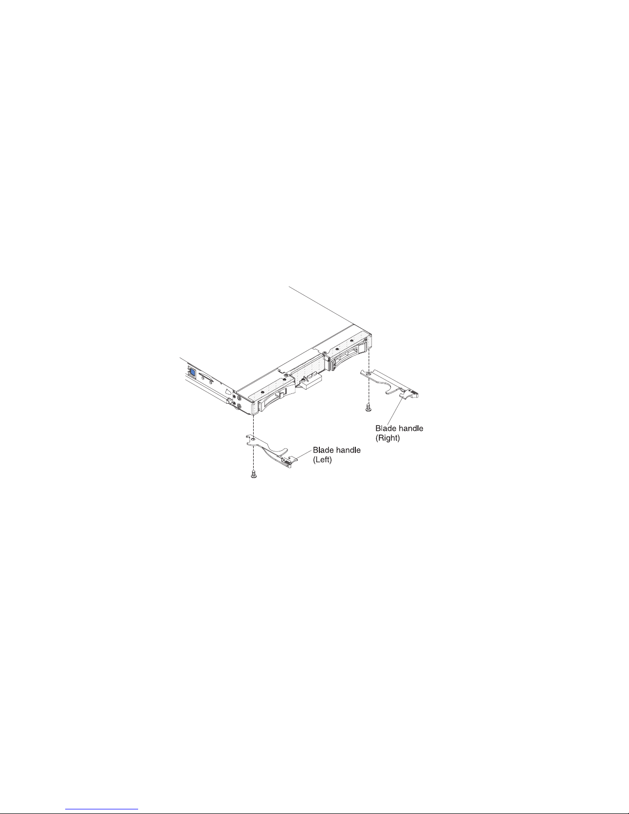
2. If you removed an expansion unit from the blade server, install it now (see
“Installing an optional expansion unit” on page 85).
3. Lower the cover so that the slots at the rear slide down onto the pins at the
rear of the blade server, as shown in the illustration. Before you close the cover,
make sure that all components are installed and seated correctly and that you
have not left loose tools or parts inside the blade server.
4. Pivot the cover to the closed position, as shown in the illustration, until it clicks
into place.
5. Install the blade server into the BladeCenter unit (see “Installing the blade
server in a BladeCenter unit” on page 53).
Removing a blade handle
Use these instructions to remove a blade handle.
The following illustration shows how to remove a blade handle.
To remove a blade handle, complete the following steps.
1. Before you begin, read “Safety” on page v and “Installation guidelines” on
page 49.
2. If the blade server is installed in a BladeCenter unit, remove it (see “Removing
the blade server from the BladeCenter unit” on page 52 for instructions).
3. Carefully lay the blade server on a flat, static-protective surface, with the cover
side down.
4. Locate the blade handle that you will be removing.
5. Locate the screw that attaches the blade handle to the blade server.
6. Remove the screw from the blade handle and save the screw in a safe place. It
is recommended to use the same screw when installing a blade handle.
7. If you are instructed to return the blade handle, follow all packaging
instructions, and use any packaging materials for shipping that are supplied to
you.
Chapter 5. Removing and replacing blade server components 57
Page 72

Installing a blade handle
Use these instructions for information about how install a blade handle.
To install a blade handle, complete the following steps:
1. Orient the blade server with the cover side down and the bezel towards you.
2. Locate where you will be installing the blade handle.
Note: The left handle and right handle are not the same part. To identify where
the blade handle should be installed, see the illustration and parts listing
provided in Chapter 4, “Parts listing,” on page 41.
3. Orient the blade handle so that the blue release latch is towards the middle of
the blade server.
4. Align the hole in the blade handle with the hole on the blade server where the
handle will be installed.
5. Use a screwdriver to install the screw that secures the blade handle to blade
server. It is recommended to install the screw that was removed when the
blade handle was removed.
6. Install the blade server into the BladeCenter unit (see “Installing the blade
server in a BladeCenter unit” on page 53).
Removing the battery
Use this information to remove the battery from the blade server.
To remove the battery, complete the following steps.
1. Before you begin, read “Safety” on page v and “Installation guidelines” on
page 49.
2. If the blade server is installed in a BladeCenter unit, remove it (see “Removing
the blade server from the BladeCenter unit” on page 52 for instructions).
3. Remove the blade server cover (see “Removing the blade server cover” on page
55 for instructions).
4. If an optional expansion unit is installed, remove the expansion unit (see
“Removing an optional expansion unit” on page 84).
5. Locate the battery on the system board.
58 BladeCenter HS22 Type 7870, 1936, and 1911: Problem Determination and Service Guide
Page 73

6. If there is a plastic cover on the battery holder, use your fingers to lift the
battery cover from the battery connector.
7. Release the battery by using your finger to press the top of the battery towards
the middle of the blade server and out of the battery connector.
8. Use your thumb and index finger to lift the battery from the socket.
9. Dispose of the battery as required by local ordinances or regulations.
Chapter 5. Removing and replacing blade server components 59
Page 74

Installing the battery
Use this information to install a battery on the system board in the blade server.
The following notes describe information that you must consider when you are
replacing the battery in the blade server.
v You must replace the battery with a lithium battery of the same type from the
same manufacturer.
v To order replacement batteries, call 1-800-426-7378 within the United States, and
1-800-465-7999 or 1-800-465-6666 within Canada. Outside the U.S. and Canada,
call your IBM marketing representative or authorized reseller.
v After you replace the battery, you must reconfigure the blade server and reset
the system date and time.
v To avoid possible danger, read and follow the following safety statement.
Statement 2
CAUTION:
When replacing the lithium battery, use only IBM Part Number 33F8354 or an
equivalent type battery recommended by the manufacturer. If your system has a
module containing a lithium battery, replace it only with the same module type
made by the same manufacturer. The battery contains lithium and can explode if
not properly used, handled, or disposed of.
Do not:
v Throw or immerse into water
v Heat to more than 100° C (212° F)
v Repair or disassemble
Dispose of the battery as required by local ordinances or regulations.
Note:
1. The following illustration shows how to install the battery in the system board.
2. The illustrations in this document might differ slightly from your hardware.
To install the battery, complete the following steps:
1. Before you begin, read “Safety” on page v and “Installation guidelines” on
page 49.
2. If the blade server is installed in a BladeCenter unit, remove it (see
“Removing the blade server from the BladeCenter unit” on page 52 for
instructions).
3. Remove the blade server cover (see “Removing the blade server cover” on
page 55 for instructions).
4. If an optional expansion unit is installed, remove the expansion unit (see
“Removing an optional expansion unit” on page 84 for instructions).
5. Follow any special handling and installation instructions that come with the
battery.
6. Locate the battery on the system board.
60 BladeCenter HS22 Type 7870, 1936, and 1911: Problem Determination and Service Guide
Page 75

7. Orient the battery so that the positive (+) side faces in towards the center of
the blade server.
8. Tilt the battery so that you can insert it into the bottom of the socket.
9. As you slide the battery into place, press the top of the battery into the socket.
10. If you removed a plastic cover from the battery holder, use your fingers to
install the battery cover on top of the battery connector.
11. Install the optional expansion unit, if you removed one from the blade server
to replace the battery (see “Installing an optional expansion unit” on page 85
for instructions).
12. Install the cover onto the blade server (see “Closing the blade server cover”
on page 56).
13. Install the blade server into the BladeCenter unit (see “Installing the blade
server in a BladeCenter unit” on page 53).
14. Turn on the blade server, start the Setup utility, and reset the configuration
(see “Using the Setup utility” on page 21 for instructions).
Chapter 5. Removing and replacing blade server components 61
Page 76
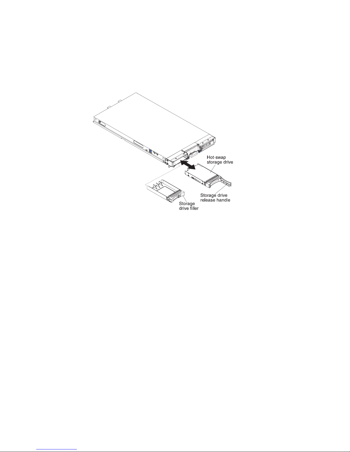
Removing a hot-swap storage drive
Use this information to remove a hot-swap storage drive.
The blade server has two SAS hot-swap storage bays for installing or removing
hot-swap storage devices, such as a SAS storage drive. To remove a hot-swap hard
disk drive or drive filler, complete the following steps.
1. Before you begin, read “Safety” on page v and “Installation guidelines” on
page 49.
2. Press the release latch (orange) on the storage drive to release the drive handle.
3. Pull the release handle to remove the drive from the storage bay.
4. If you are instructed to return the storage drive, follow all packaging
instructions, and use any packaging materials for shipping that are supplied to
you.
62 BladeCenter HS22 Type 7870, 1936, and 1911: Problem Determination and Service Guide
Page 77

Installing a hot-swap storage drive
Use these instructions to install a hot-swap storage drive into the blade server.
The blade server has two SAS storage bays for installing hot-swap storage drives,
such as a hot-swap SAS hard disk drive. One storage drive might already be
installed in the blade server in storage bay 0. If the blade server is equipped with
one storage drive, you can install an additional drive in storage bay 1. The blade
server supports using RAID 0 or RAID 1 when two storage drives of the same
interface type are installed. See “Configuring a RAID array” on page 36 for
information about SAS RAID configuration.
To install a hot-swap storage drive or drive filler, complete the following steps.
1. Identify the SAS storage bay (storage bay 0 or storage bay 1) in which the
hot-swap storage drive will be installed (see “Blade server connectors” on page
15).
2. If a storage-bay filler is installed, remove it from the blade server by pulling the
release lever and sliding the filler away from the blade server (see “Removing a
hot-swap storage drive” on page 62).
3. Touch the static-protective package that contains the hot-swap storage drive to
any unpainted metal surface on the BladeCenter unit or any unpainted metal
surface on any other grounded rack component; then, remove the hard disk
drive from the package.
4. Open the release lever on the hot-swap storage drive and slide the drive into
the storage bay until it is firmly seated in the connector.
5. Lock the hot-swap storage drive into place by closing the release lever.
Chapter 5. Removing and replacing blade server components 63
Page 78
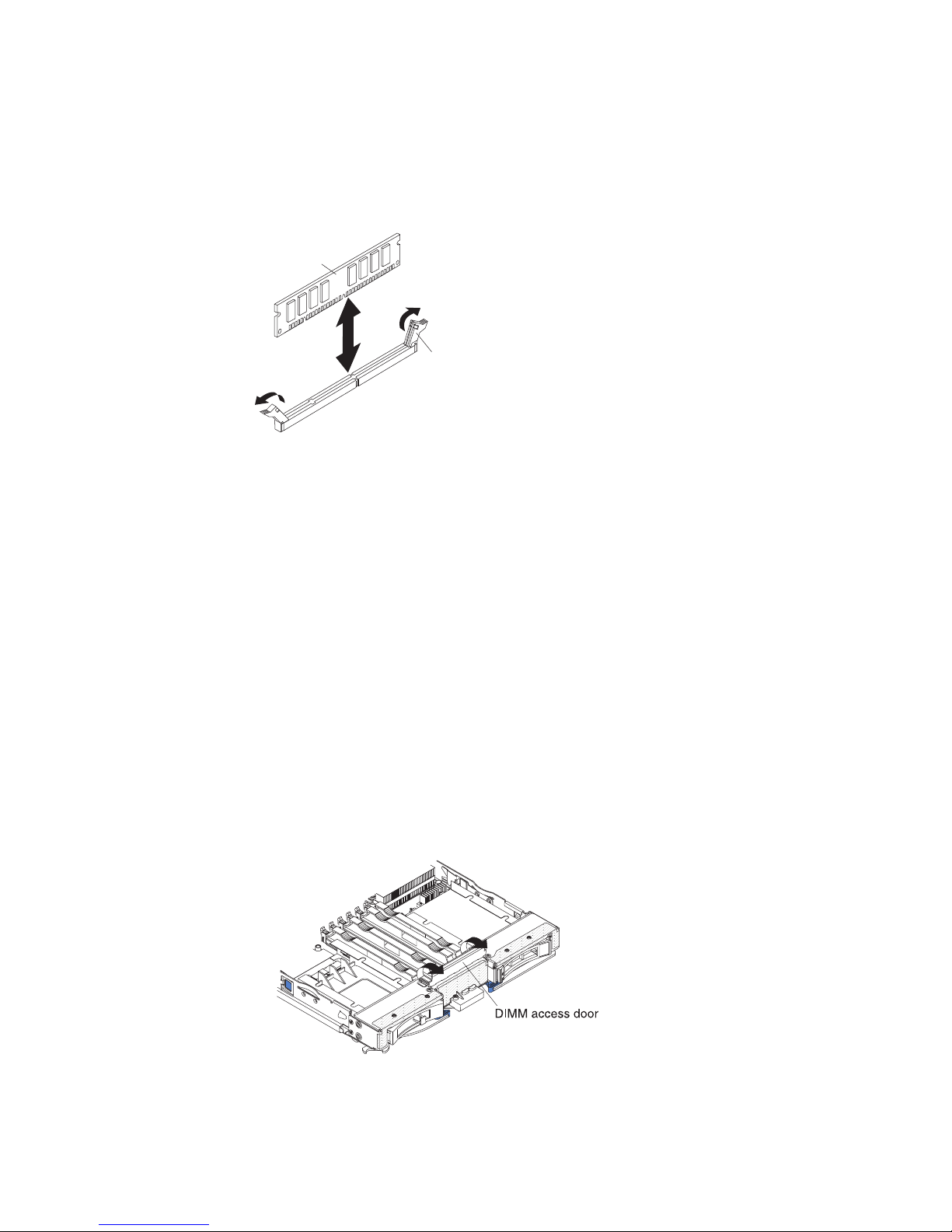
Removing a memory module
Use this information to remove a memory module from the blade server.
The following illustration shows how to remove a DIMM from the blade server.
This information also applies to removing a DIMM filler.
DIMM
Retaining
clip
To remove a DIMM, complete the following steps.
1. Before you begin, read “Safety” on page v and “Installation guidelines” on
page 49.
2. If the blade server is installed in a BladeCenter unit, remove it (see “Removing
the blade server from the BladeCenter unit” on page 52).
3. Remove the blade server cover (see “Removing the blade server cover” on page
55).
4. If an optional expansion unit is installed, remove the expansion unit (see
“Removing an optional expansion unit” on page 84).
5. Locate the DIMM connectors (see “Blade server connectors” on page 15).
Determine which DIMM you want to remove from the blade server.
Attention: To avoid breaking the retaining clips or damaging the DIMM
connectors, handle the clips gently.
6. Move the retaining clips on the ends of the DIMM connector to the open
position by pressing the retaining clips away from the center of the DIMM
connector.
Note: To access DIMM connector seven through twelve, use your fingers to lift
the DIMM access door.
7. Using your fingers, pull the DIMM out of the connector.
64 BladeCenter HS22 Type 7870, 1936, and 1911: Problem Determination and Service Guide
Page 79

8. Install a DIMM or DIMM filler in each empty DIMM connector (see “Installing
a memory module”).
Note: A DIMM or DIMM filler must occupy each DIMM socket before the
blade server is turned on.
9. If you are instructed to return the DIMM, follow all packaging instructions, and
use any packaging materials for shipping that are supplied to you.
Installing a memory module
Use these instructions to install memory modules in the blade server.
The blade server has a total of twelve direct inline memory module (DIMM) slots.
The blade server supports very low profile (VLP) DDR3 DIMMs with error code
correction (ECC) in 1 GB, 2 GB, 4 GB, 8 GB, and 16 GB capacities. For a list of
supported DIMMs for the blade server, see Chapter 4, “Parts listing,” on page 41.
After you install or remove a DIMM, you must change and save the new
configuration information by using the Setup utility. When you turn on the blade
server, a message indicates that the memory configuration has changed. Start the
Setup utility and select Save Settings (see “Setup utility menu” on page 22 for
more information) to save changes.
The memory is accessed internally through the system using six channels. Each
channel contains two DIMM connectors. The following table lists each channel and
which DIMM connectors belong to the channel.
Table 2. Memory channel configuration
Memory channel DIMM connector
Channel 0 DIMM connector 1 and 2
Channel 1 DIMM connector 5 and 6
Channel 2 DIMM connector 3 and 4
Channel 3 DIMM connector 7 and 8
Channel 4 DIMM connector 11 and 12
Channel 5 DIMM connector 9 and 10
Depending on the memory mode that is set in the Setup utility, the blade server
can support a minimum of 1 GB and a maximum of 48 GB of system memory on
the system board in a blade server with one processor. If two microprocessors are
installed, the blade server can support a minimum of 2 GB and a maximum of 96
GB of system memory. There are two different memory modes:
v Independent channel mode: Independent channel mode gives a maximum of 96
GB of usable memory with one CPU installed, and 192 GB of usable memory
with 2 CPUs installed (using 16 GB DIMMs). The DIMMs can be installed
without matching sizes. See the table below for the memory installation order.
Table 3. System memory configuration for independent channel mode (1 microprocessor)
Installed
memory
1 DIMM X
2 DIMMs X X
3 DIMMs X X X
123456789101112
DIMM socket
Chapter 5. Removing and replacing blade server components 65
Page 80

Table 3. System memory configuration for independent channel mode (1 microprocessor) (continued)
Installed
memory
4 DIMMs X X X X
5 DIMMs X X X X X
6 DIMMs X XXXXX
Table 4. System memory configuration for independent channel mode (2 microprocessors)
Installed
memory
2 DIMMs X X
3 DIMMs X X X
4 DIMMs X X X X
5 DIMMs X X X X X
6 DIMMs X X X X X X
7 DIMMs X X X X X X X
8 DIMMs X X X X X X X X
9 DIMMs X X X X X X X X X
10 DIMMs X X X X X X X X X X
11 DIMMs X XXXXXXXXX X
12 DIMMs X XXXXXXXXXXX
123456789101112
123456789101112
DIMM socket
DIMM socket
v Mirrored channel mode: In mirrored channel mode, channels 2 and 5 are
unused. The memory contents on channel 0 are duplicated in channel 1, and the
memory contents of channel 3 are duplicated in channel 4. The effective memory
available to the system is only half of that installed. The maximum available
memory (with 16 GB DIMMs) is 32 GB for a single CPU system and 64 GB for a
dual CPU system.
Important: The memory configuration of channel 0 must match that of channel
1, and the memory configuration of channel 3 must match that of channel 4. For
example, ifa4GBDual Rank DIMM is installed into the DIMM2 connector,
thena4GBDual Rank DIMM must also be installed into the DIMM6 connector.
Table 2 on page 65 lists each channel and which DIMM connectors belong to the
channel.
The following table shows the order that memory DIMMs are installed to use a
mirrored channel mode.
Table 5. System memory configuration for mirrored channel mode (1 microprocessor)
Installed
memory
2 DIMMs X X
4 DIMMs X X X X
123456789101112
DIMM socket
66 BladeCenter HS22 Type 7870, 1936, and 1911: Problem Determination and Service Guide
Page 81

Table 6. System memory configuration for mirrored channel mode (2 microprocessors)
Installed
memory
4 DIMMs X X X X
6 DIMMs X X X X X X
8 DIMMs X X X X X X X X
123456789101112
DIMM socket
v Spare channel mode: In spare channel mode, channel 2 is the spare of the active
channels 0 and 1. The spare channel is not available as active memory. The
maximum memory available (with 16 GB DIMMs) is 64 GB in a single CPU
system and 128 GB in a dual CPU system. All three channels must have
identical population with regards to size and organization. DIMMs within a
channel do not have to be identical. The population ordering for spare channel
mode is shown in the table below.
Note: Spare channel mode is only supported if the blade server has an Intel
Xeon 5600 series microprocessor. Use the Setup utility to view the system
summary and verify the type of microprocessor installed in your blade server
(see “Using the Setup utility” on page 21).
The following table shows the order that memory DIMMs are installed to use
spare channel mode.
Table 7. System memory configuration for spare channel mode (1 microprocessor)
Installed
memory
3 DIMMs X X X
6 DIMMs X X X X X X
1 2 3 4 5 6 7 8 9 101112
DIMM socket
Table 8. System memory configuration for spare channel mode (2 microprocessors)
Installed
memory
6 DIMMs X X X X X X
9 DIMMs XXXXXX X X X
12 DIMMs XXXXXXXXXXXX
123456789101112
DIMM socket
To install a DIMM, complete the following steps:
1. Locate the DIMM connectors (see “Blade server connectors” on page 15).
Determine which DIMM connector you will be installing memory into.
2. If a DIMM filler or another memory module is already installed in the DIMM
connector, remove it (see “Removing a memory module” on page 64).
Note: A DIMM or DIMM filler must occupy each DIMM socket before the
blade server is turned on.
3. If you are installing a DIMM in DIMM connector seven through twelve, use
your fingers to lift the DIMM access door.
Chapter 5. Removing and replacing blade server components 67
Page 82

4. Touch the static-protective package that contains the DIMM to any unpainted
metal surface on the BladeCenter unit or any unpainted metal surface on any
other grounded rack component in the rack in which you are installing the
DIMM for at least two seconds; then, remove the DIMM from its package.
5. To install the DIMMs, repeat the following steps for each DIMM that you
install:
DIMM
Retaining
clip
a. Make sure that the retaining clips are in the open position, away from the
center of the DIMM connector.
b. Turn the DIMM so that the DIMM keys align correctly with the DIMM
connector on the system board.
Attention: To avoid breaking the retaining clips or damaging the DIMM
connectors, handle the clips gently.
c. Press the DIMM into the DIMM connector. The retaining clips will lock the
DIMM into the connector.
d. Make sure that the small tabs on the retaining clips are in the notches on
the DIMM. If there is a gap between the DIMM and the retaining clips, the
DIMM has not been correctly installed. Press the DIMM firmly into the
connector, and then press the retaining clips toward the DIMM until the
tabs are fully seated. When the DIMM is correctly installed, the retaining
clips are parallel to the sides of the DIMM.
6. If the DIMM access door is open, use your fingers to close it.
7. Install the cover onto the blade server (see “Closing the blade server cover” on
page 56).
8. Install the blade server into the BladeCenter unit (see “Installing the blade
server in a BladeCenter unit” on page 53).
Removing a USB Flash key
Use this information to remove a USB Flash key from the blade server.
68 BladeCenter HS22 Type 7870, 1936, and 1911: Problem Determination and Service Guide
Page 83

The following illustration shows the removal of a USB Flash key from the blade
server.
To remove the USB Flash key, complete the following steps.
1. Before you begin, read “Safety” on page v and “Installation guidelines” on
page 49.
2. If the blade server is installed in a BladeCenter unit, remove it (see “Removing
the blade server from the BladeCenter unit” on page 52).
3. Remove the blade server cover (see “Removing the blade server cover” on page
55).
4. If an optional expansion unit is installed, remove the expansion unit (see
“Removing an optional expansion unit” on page 84).
5. If an optional CIOv expansion card is installed, remove the CIOv expansion
card (see “Removing a CIOv-form-factor expansion card” on page 71).
6. Locate the USB Flash key on the system board (see “Blade server connectors”
on page 15).
Chapter 5. Removing and replacing blade server components 69
Page 84

7. Using your fingers, pull the USB Flash key out of the connector.
8. If you are instructed to return the USB Flash key, follow all packaging
instructions, and use any packaging materials for shipping that are supplied to
you.
Installing a USB Flash key
Use these instructions to install a USB Flash key in the blade server.
The following illustration shows the installation of the USB Flash key.
To install a USB module, complete the following steps:
1. If a CIOv expansion card is installed, remove the expansion card (see
“Removing a CIOv-form-factor expansion card” on page 71).
2. Locate the USB connector on the blade server (see “Blade server connectors” on
page 15).
3. Touch the static-protective package that contains the USB Flash key to any
unpainted metal surface on the BladeCenter unit or any unpainted metal surface
on any other grounded rack component in the rack in which you are installing
the USB module for at least two seconds; then, remove the USB module from
its package.
4. Orient the connector on the USB Flash key with the USB connector on the
blade server.
5. Use your fingers to push the USB Flash key into the USB connector on the
blade server.
6. If a CIOv expansion card was removed during the install process, install the
expansion card (see “Installing a CIOv-form-factor expansion card” on page
75).
7. Install the cover onto the blade server (see “Closing the blade server cover” on
page 56).
8. Install the blade server into the BladeCenter unit (see “Installing the blade
server in a BladeCenter unit” on page 53).
70 BladeCenter HS22 Type 7870, 1936, and 1911: Problem Determination and Service Guide
Page 85

Removing an I/O expansion card
The following sections describe how to remove the following expansion cards:
v vertical-combination-I/O (CIOv)
v horizontal-combination-form-factor (CFFh)
v CIOv storage interface card
Removing a CIOv-form-factor expansion card
Use these instructions to remove a CIOv-form-factor expansion card in the blade
server.
The following illustration shows how to remove a vertical-combination-I/O (CIOv)
expansion card.
To removel a CIOv expansion card, complete the following steps:
1. Before you begin, read “Safety” on page v and “Installation guidelines” on
page 49.
2. If the blade server is installed in a BladeCenter unit, remove it (see “Removing
the blade server from the BladeCenter unit” on page 52 for instructions).
3. Carefully lay the blade server on a flat, static-protective surface.
4. Open the blade server cover (see “Removing the blade server cover” on page
55 for instructions).
5. Touch the static-protective package that contains the expansion card to any
unpainted metal surface on the BladeCenter unit or any unpainted metal surface
on any other grounded rack component; then, remove the expansion card from
the package.
Chapter 5. Removing and replacing blade server components 71
Page 86

6. Locate the CIOv expansion connector (see “Blade server connectors” on page
15).
7. Using your fingers, move the retaining clips away from the CIOv card; then, lift
the card out of the connector.
Removing a horizontal-compact-form-factor expansion card
Use these instructions to remove a compact-form-factor expansion card from the
blade server.
The following illustration shows how to remove a horizontal-compact-form-factor
(CFFh) expansion card.
To remove a CFFh expansion card, complete the following steps:
1. Before you begin, read “Safety” on page v and “Installation guidelines” on
page 49.
2. If the blade server is installed in a BladeCenter unit, remove it (see “Removing
the blade server from the BladeCenter unit” on page 52 for instructions).
3. Carefully lay the blade server on a flat, static-protective surface.
4. Open the blade server cover (see “Removing the blade server cover” on page
55 for instructions).
5. Locate the CFFh expansion card. The CFFh is installed into the blade expansion
connector (see “Blade server connectors” on page 15).
6. Use your fingers to hold the edge of the CFFh expansion card where it
connects to the blade expansion connector; then, lift up on the card.
7. Pull the card away from the expansion-card standoff.
72 BladeCenter HS22 Type 7870, 1936, and 1911: Problem Determination and Service Guide
Page 87

Removing a storage interface card
Use this information to remove a storage interface card from the blade server.
The storage interface card controls the SAS hot-swap storage drives. The following
illustrations and installation instructions shows how to remove a
ServeRAID-MR10ie CIOv storage interface card from the blade server. The
illustrations and removal instructions are similar for other CIOv storage interface
cards.
To remove a storage interface card, complete the following steps.
1. Before you begin, read “Safety” on page v and “Installation guidelines” on
page 49.
2. If the blade server is installed in a BladeCenter unit, remove it (see “Removing
the blade server from the BladeCenter unit” on page 52 for instructions).
3. Remove the blade server cover (see “Removing the blade server cover” on page
55 for instructions).
4. If an optional expansion unit is installed, remove the expansion unit (see
“Removing an optional expansion unit” on page 84). The storage-interface-card
option includes the storage interface card, backup battery, and backup-battery
cable. These parts can be removed separately from each other.
5. To remove the storage interface card, complete the following steps.
a. Locate the storage interface card installed in the CIOv connector on the
system board (see “Blade server connectors” on page 15).
Chapter 5. Removing and replacing blade server components 73
Page 88

b. Gently push the retaining clips away from the expansion card; then, lift the
card out of the expansion-card connector.
c. Remove the cable from the storage interface card by holding the card in one
hand; then, use your other hand to pull the cable away from the card. When
pulling the cable, make sure that you hold the cable where there is a blue
touchpoint.
6. To remove the backup-battery cable, complete the following steps.
a. Remove the cable from the storage interface card by holding the blue
touchpoint on the cable; then, pull the cable away from the card.
b. Remove the cable from the backup battery by holding the blue touchpoint
on the cable; then, pull the cable away from the backup battery.
7. The backup battery is installed in DIMM connector seven. To remove the
backup battery, complete the following steps.
a. If you have not already done so, remove the backup-battery cable from the
backup battery by holding the blue touchpoint on the cable; then, pull the
cable away from the backup battery.
b. Remove the backup battery from the DIMM connector seven by using the
instructions to remove a memory module (see “Removing a memory
module” on page 64).
8. Remove the backup battery from DIMM connector seven.
9. If you are instructed to return the storage interface card, follow all packaging
instructions, and use any packaging materials for shipping that are supplied to
you.
74 BladeCenter HS22 Type 7870, 1936, and 1911: Problem Determination and Service Guide
Page 89

Installing an I/O expansion card
The following sections describe how to install the following expansion cards:
v vertical-combination-I/O (CIOv)
v horizontal-combination-form-factor (CFFh)
v CIOv storage interface card
Installing a CIOv-form-factor expansion card
Use these instructions to install a CIOv-form-factor expansion card in the blade
server.
The blade server supports a vertical-combination-I/O (CIOv) expansion card and a
horizontal-combination-form-factor (CFFh) expansion card. The following
illustration shows the location and installation of a CIOv expansion card.
Attention: Before you install one of the following CIOv expansion cards in the
blade server, make sure the PCIe speed is set to Gen1. You can configure the PCIe
speed in the Setup utility by selecting System Settings and Devices and I/O Ports.
v Ethernet Expansion Card (CIOv) for IBM BladeCenter
v QLogic 4 Gb Fibre Channel Expansion Card (CIOv) for IBM BladeCenter
v SAS Connectivity Card (CIOv) for IBM BladeCenter
v ServeRAID-MR10ie (CIOv) Controller for IBM BladeCenter
To install a CIOv expansion card, complete the following steps:
1. Touch the static-protective package that contains the expansion card to any
unpainted metal surface on the BladeCenter unit or any unpainted metal surface
on any other grounded rack component; then, remove the expansion card from
the package.
2. Locate the CIOv expansion connector (see “Blade server connectors” on page
15).
3. Orient the connector on the expansion card with the CIOv expansion connector
on the system board; then, press the card into the CIOv expansion connector.
4. Firmly press on the indicated locations to seat the expansion card.
Note: For device-driver and configuration information to complete the
installation of the expansion card, see the documentation that comes with the
expansion card.
Chapter 5. Removing and replacing blade server components 75
Page 90

5. Install the cover onto the blade server (see “Closing the blade server cover” on
page 56).
6. Install the blade server into the BladeCenter unit (see “Installing the blade
server in a BladeCenter unit” on page 53).
Installing a horizontal-compact-form-factor expansion card
Use these instructions to install a compact-form-factor expansion card in the blade
server.
The blade server supports a horizontal-combination-form-factor (CFFh) expansion
card. The following illustration shows how to install a CFFh expansion card.
Expansion
card
Blade
expansion
Expansion
card
standoff
connector
cover
Attention: Before you install one of the following CFFh expansion cards in the
blade server, make sure the PCIe speed is set to Gen1. You can configure the PCIe
speed in the Setup utility by selecting System Settings and Devices and I/O Ports.
v 2/4 Port Ethernet Expansion Card for BladeCenter
v Broadcom 10 Gb 2-port Ethernet Expansion Card (CFFh) for IBM BladeCenter
v Broadcom 10 Gb 4-port Ethernet Expansion Card (CFFh) for IBM BladeCenter
To install a CFFh expansion card, complete the following steps:
1. Locate the blade server expansion connector (see “Blade server connectors” on
page 15).
2. If a cover is installed on the blade expansion connector, remove it by using
your fingers to lift the cover from the blade expansion connector.
3. Touch the static-protective package that contains the expansion card to any
unpainted metal surface on the BladeCenter unit or any unpainted metal surface
on any other grounded rack component; then, remove the expansion card from
the package.
4. Orient the expansion card and slide the slots at the back end of the card onto
the pins on the expansion-card standoff; then, gently pivot the card into the
blade server expansion connector.
5. Firmly press on the indicated locations to seat the expansion card.
Note: For device-driver and configuration information to complete the
installation of the expansion card, see the documentation that comes with the
expansion card.
6. Install the cover onto the blade server (see “Closing the blade server cover” on
page 56).
76 BladeCenter HS22 Type 7870, 1936, and 1911: Problem Determination and Service Guide
Page 91
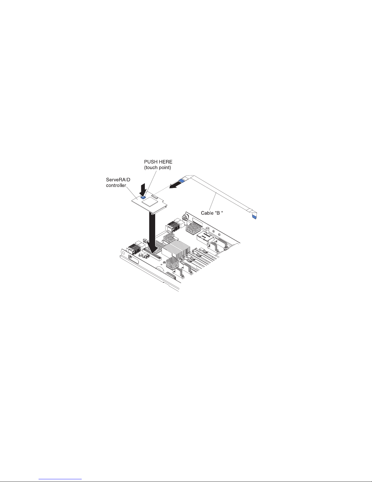
7. Install the blade server into the BladeCenter unit (see “Installing the blade
server in a BladeCenter unit” on page 53).
Installing a storage interface card
Use this information to install a storage interface card in the blade server.
The storage interface card controls the SAS hot-swap storage drives. The following
illustrations and installation instructions shows how to install a ServeRAID-MR10ie
controller into the CIOv expansion connector of the blade server. The illustrations
and installation instructions are similar for other CIOv storage interface cards.
Note: The backup-battery will be installed in DIMM connector seven and might
affect how much memory is recognized by the blade server. Review the tables in
“Installing a memory module” on page 65 to make sure that your memory
configuration will not be affected.
Attention: Before you install a ServeRAID-MR10ie controller in the blade server,
make sure the PCIe speed is set to Gen1. You can configure the PCIe speed in the
Setup utility by selecting System Settings and Devices and I/O Ports.
To install a storage interface card, complete the following steps.
1. Locate the CIOv expansion connector (see “Blade server connectors” on page
15).
2. Touch the static-protective package that contains the storage interface card to
any unpainted metal surface on the BladeCenter unit or any unpainted metal
surface on any other grounded rack component; then, remove the storage
interface card from the package.
3. If an interposer card is installed on the storage interface card, remove it.
Chapter 5. Removing and replacing blade server components 77
Page 92
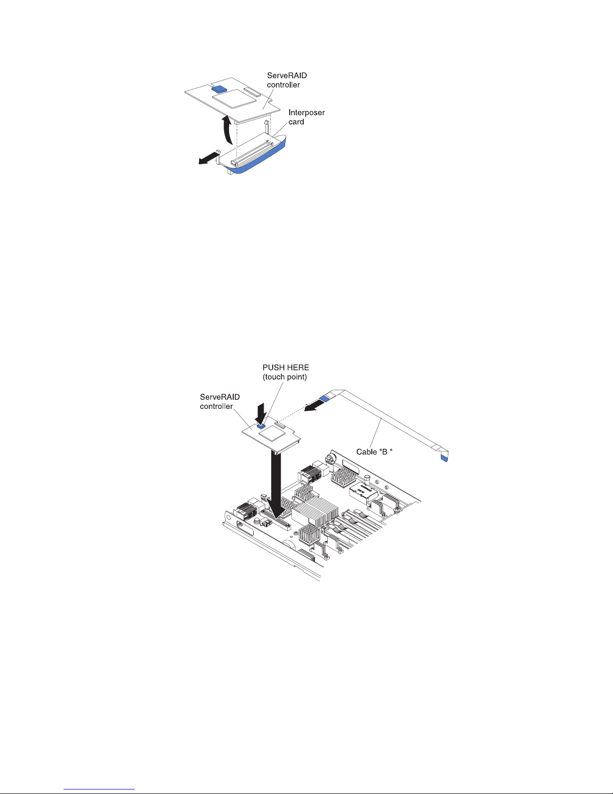
a. If the interposer has a pull strap, move the pull strap away from the
storage interface card. If the pull strap surrounds the storage interface
card, the pull strap will interfere with the removal of the interposer card.
b. Press out on the plastic latch that holds the interposer card to the storage
interface card and simultaneously lift up on the controller, as shown.
c. Separate the interposer card from the storage interface card and store the
interposer card in a safe place.
4. Install the backup-battery cable to the storage interface card.
a. If you are installing a ServeRAID-MR10ie controller, select cable "B" from
the packaging.
b. Locate the end of the cable marked “EXPANSION CARD”; then, with the
blue side of the cable end facing up, carefully insert the cable end into the
cable connector on the ServeRAID controller.
5. Orient the connector on the storage interface card with the CIOv expansion
connector on the system board; then, press the storage interface card into the
CIOv expansion connector.
6. Firmly press on the indicated locations to seat the storage interface card.
Note: For device-driver and configuration information to complete the
installation of the expansion card, see the documentation that comes with the
storage interface card.
7. Install the backup battery for the storage interface card into DIMM connector
seven (see “Blade server connectors” on page 15 and “Installing a memory
78 BladeCenter HS22 Type 7870, 1936, and 1911: Problem Determination and Service Guide
Page 93

module” on page 65).
8. Install the backup-battery cable to the backup battery. The side of the cable
with the blue touchpoint should be oriented towards the center of the blade
server.
9. Orient the backup-battery cable so that it lays flat over the top of the heat sink
for microprocessor two.
10. If you removed an optional expansion unit, reinstall it (see “Installing an
optional expansion unit” on page 85).
11. Install the cover onto the blade server (see “Closing the blade server cover” on
page 56).
12. Install the blade server into the BladeCenter unit (see “Installing the blade
server in a BladeCenter unit” on page 53).
Chapter 5. Removing and replacing blade server components 79
Page 94

Removing and replacing Tier 2 CRUs
Use this information to determine the guidelines for installing a Tier 2 CRU into
your blade server.
You may install a Tier 2 CRU yourself or request IBM to install it, at no additional
charge, under the type of warranty service that is designated for the server.
The illustrations in this document might differ slightly from your hardware.
Removing the bezel assembly
Use this information to remove the bezel assembly from the blade server.
The following illustration shows how to remove a bezel assembly from a blade
server.
Note:
1. The illustrations in this document might differ slightly from your hardware.
To remove the bezel assembly, complete the following steps.
1. Before you begin, read “Safety” on page v and “Installation guidelines” on
page 49.
2. If the blade server is installed in a BladeCenter unit, remove it (see
“Removing the blade server from the BladeCenter unit” on page 52 for
instructions).
3. Open the blade server cover (see “Removing the blade server cover” on page
55 for instructions).
4. If an optional expansion unit is installed, remove it (see “Removing an
optional expansion unit” on page 84).
5. Carefully lay the blade server on a flat, static-protective surface, with the
cover side down.
6. Locate the four screws that secure the bezel assembly to the blade server base
assembly.
80 BladeCenter HS22 Type 7870, 1936, and 1911: Problem Determination and Service Guide
Page 95

7. Use a screwdriver to remove the four screws that secure the bezel assembly to
the blade server base assembly. Save the screws in a safe place. It is
recommended to use the same screws when installing the bezel assembly.
8. While holding the bezel assembly and the blade server, rotate the blade server
so that the cover side is up.
9. Lift the bezel assembly away from the blade server.
10. If you are instructed to return the bezel assembly, follow all packaging
instructions, and use any packaging materials for shipping that are supplied
to you.
Installing the bezel assembly
Use this information to install a bezel assembly in the blade server.
Note:
1. The following illustration shows how to install a bezel assembly in a blade
server.
2. The illustrations in this document might differ slightly from your hardware.
To install the bezel assembly, complete the following steps.
1. If an optional expansion unit is installed, remove it (see “Removing an optional
expansion unit” on page 84).
2. If the control panel was removed, install it (see “Installing the control panel” on
page 83).
3. Orient the bezel with the front of the blade server, aligning the screw holes on
the bezel with the holes on the blade server.
Chapter 5. Removing and replacing blade server components 81
Page 96

4. Use your hand to keep the bezel assembly tight against the blade server; then,
rotate the blade server so that the bottom is now facing up.
5. Use a screwdriver to install the four screws that secure the bezel assembly to
the blade server. It is recommended to use the same screws that were removed
when the bezel assembly was removed.
6. Orient the blade server so that the bottom of the blade server is down.
7. Install the optional expansion unit, if you removed one from the blade server
(see “Installing an optional expansion unit” on page 85 for instructions).
8. Install the cover onto the blade server (see “Closing the blade server cover” on
page 56).
9. Install the blade server into the BladeCenter unit (see “Installing the blade
server in a BladeCenter unit” on page 53).
Removing the control panel
Use this information to remove the control panel from the blade server.
Note:
1. The following illustration shows the locations of the control panel on the
system board.
2. The illustrations in this document might differ slightly from your hardware.
To remove the control panel, complete the following steps.
Control panel connector
Control panel cable
1. Before you begin, read “Safety” on page v and “Installation guidelines” on
page 49.
2. If the blade server is installed in a BladeCenter unit, remove it (see “Removing
the blade server from the BladeCenter unit” on page 52).
3. Remove the blade server cover (see “Removing the blade server cover” on page
55).
4. If an optional expansion unit is installed, remove the expansion unit (see
“Removing an optional expansion unit” on page 84).
5. Remove the bezel assembly (see “Removing the bezel assembly” on page 80).
6. Locate the control-panel connector on the system board (see “Blade server
connectors” on page 15).
7. Using your fingers, pull the control-panel cable out of the connector; then lift
the control panel from the blade server.
8. If you are instructed to return the control panel, follow all packaging
instructions, and use any packaging materials for shipping that are supplied to
you.
82 BladeCenter HS22 Type 7870, 1936, and 1911: Problem Determination and Service Guide
Page 97

Installing the control panel
Use these instructions to install the control panel in the blade server.
The blade server has a control panel that provides controls and information LEDs
for the blade server (see “Blade server controls and LEDs” on page 11). The
following illustration shows how to install the control panel.
To install the control panel, complete the following steps:
1. Locate the control-panel connector on the blade server (see “Blade server
connectors” on page 15).
2. Touch the static-protective package that contains the control panel to any
unpainted metal surface on the BladeCenter unit or any unpainted metal surface
on any other grounded rack component in the rack in which you are installing
the control panel for at least two seconds; then, remove the USB module from
its package.
3. Orient the control panel so the cable aligns with the control-panel connector
and the control panel is positioned at the front of the blade server.
4. Use your fingers to install the control-panel cable into the control-panel
connector on the blade server.
5. Install the bezel assembly (see “Installing the bezel assembly” on page 81).
6. Install the optional expansion unit, if you removed one from the blade server to
replace the battery (see “Installing an optional expansion unit” on page 85 for
instructions).
7. Install the cover onto the blade server (see “Closing the blade server cover” on
page 56).
8. Install the blade server into the BladeCenter unit (see “Installing the blade
server in a BladeCenter unit” on page 53).
Control panel connector
Control panel cable
Chapter 5. Removing and replacing blade server components 83
Page 98

Removing and replacing field replaceable units (FRUs)
Use this information to remove and replace field replaceable units (FRUs).
FRUs must be installed only by trained service technicians. The illustrations in this
document might differ slightly from your hardware.
Removing an optional expansion unit
Use these instructions to remove the optional expansion unit from the blade server.
To remove an optional expansion unit, complete the following steps:
Expansion unit
Blade server
cover release
Blade server
cover release
1. Before you begin, read “Safety” on page v and “Installation guidelines” on
page 49.
2. If the blade server is installed in a BladeCenter unit, remove it (see “Removing
the blade server from the BladeCenter unit” on page 52 for instructions).
3. Carefully lay the blade server on a flat, static-protective surface, with the cover
side up.
4. Remove the blade server cover, if one is installed (see “Removing the blade
server cover” on page 55 for instructions).
5. Remove the expansion unit:
a. If the expansion unit has an extraction device, use the extraction device to
disengage the expansion unit from the blade server. These extraction
devices can be of several types, including thumbscrews or levers. See the
instructions provided with the expansion unit for detailed instructions for
removing the expansion unit.
b. If the expansion unit does not have an extraction device, press the blade
server cover release on each side of the blade server and lift the expansion
unit from the blade server.
c. Rotate the expansion unit open; then, lift the expansion unit from the blade
server.
6. If you are instructed to return the expansion unit, remove from it any options
that you have installed; then, follow all packaging instructions, and use any
packaging materials for shipping that are supplied to you.
84 BladeCenter HS22 Type 7870, 1936, and 1911: Problem Determination and Service Guide
Page 99

Installing an optional expansion unit
Use these instructions to install an optional expansion unit.
Attention: If a horizontal combination-form-factor (CFFh) expansion card is
installed on the blade server system board, you cannot install an optional
expansion unit.
Notes:
1. All devices should be installed in an expansion unit before attaching it to the
blade server.
2. After you install one or more expansion units on your blade server, the
combined blade server and expansion units together occupy adjacent blade
bays in the BladeCenter unit. Enough power modules must be installed in the
BladeCenter unit to power the blade bays in which you install the blade server
and expansion units.
3. The following illustration shows an optional expansion unit in a blade server.
4. The illustrations in this document might differ slightly from your hardware.
To install an optional expansion unit, complete the following steps.
Expansion unit
Blade server
cover release
Blade server
cover release
1. Locate the blade expansion connector on the blade server system board or the
expansion unit and remove the cover if one is installed (see “Blade server
connectors” on page 15).
2. Touch the static-protective package that contains the optional expansion unit to
any unpainted metal surface on the BladeCenter unit or any unpainted metal
surface on any other grounded rack component; then, remove the optional
expansion unit from the package.
3. Orient the optional expansion unit as shown in the illustration.
4. Lower the expansion unit so that the slots at the rear slide down onto the cover
pins at the rear of the blade server; then, pivot the expansion unit down onto
the blade server.
5. If the expansion unit has an extraction device (such as a thumbscrew or a
lever), use it to fully engage the expansion unit on the blade server; otherwise,
press the expansion unit firmly into the closed position until it clicks into place.
To install an optional GPU adapter into a GPU expansion unit, see “Installing a
GPU adapter in the BladeCenter GPU expansion unit” on page 88. To install an
option into another type of expansion unit, refer to the documentation
provided with the expansion unit.
Chapter 5. Removing and replacing blade server components 85
Page 100

6. If additional expansion units are being installed, repeat steps 4 through 8 for
each expansion blade; otherwise continue with step 11.
7. Follow the instructions provided with the expansion unit to install an option in
the expansion unit.
8. If this is the last expansion blade being installed, install the cover provided
with the expansion unit (see “Closing the blade server cover” on page 56).
9. Install the blade server into the BladeCenter unit (see “Installing the blade
server in a BladeCenter unit” on page 53).
Removing a GPU adapter from the BladeCenter GPU
expansion unit
Use this information to remove a GPU adapter from the BladeCenter GPU
expansion unit.
Note:
1. The following illustration shows how to remove a GPU adapter from the
BladeCenter GPU expansion unit.
2. The illustrations in this document might differ slightly from your hardware.
To remove a GPU adapter from the BladeCenter GPU expansion unit, complete the
following steps:
1. Before you begin, read “Safety” on page v and “Installation guidelines” on
page 49.
2. If the blade server is installed in a BladeCenter unit, remove it (see “Removing
the blade server from the BladeCenter unit” on page 52 for instructions).
3. Remove the blade server cover (see “Removing the blade server cover” on page
55 for instructions).
4. If an expansion blade is installed on the expansion blade containing the adapter
you want to remove, remove it (see “Removing an optional expansion unit” on
page 84.)
5. Remove the expansion-blade riser assembly from the BladeCenter GPU
expansion blade:
a. Disconnect the auxiliary power cable (A) from the GPU adapter, as shown
in the following illustration.
86 BladeCenter HS22 Type 7870, 1936, and 1911: Problem Determination and Service Guide
A
B
 Loading...