

Page 1

IBM BladeCenter HX5
Type 7873, 7872, 1910 and 1909
Installation and User's Guide
Page 2

Page 3

IBM BladeCenter HX5
Type 7873, 7872, 1910 and 1909
Installation and User's Guide
Page 4

Note
Before using this information and the product it supports, read the general information in
“Notices” on page 119, the Warranty Information document, and the IBM Safety Information and the
Environmental Notices and User Guide documents on the IBM Documentation CD.
Seventh Edition (May 2011)
© Copyright IBM Corporation 2011.
US Government Users Restricted Rights – Use, duplication or disclosure restricted by GSA ADP Schedule Contract
with IBM Corp.
Page 5

Contents
Safety ...............v
Safety statements ............vi
Chapter 1. Introduction ........1
Related documentation ...........3
The IBM Documentation CD .........4
Hardware and software requirements .....4
Using the Documentation Browser ......5
Notices and statements in this document .....6
Features and specifications..........6
What your blade server offers ........8
Reliability, availability, and serviceability features. . 10
IBM Systems Director ...........11
Major components of the blade server .....12
Working with a scalable blade complex .....13
Chapter 2. Power, controls, and
indicators .............15
Turning on the blade server .........15
Turning off the blade server .........15
Blade server controls and LEDs........16
Scalability indicators ..........20
Blade server connectors - BladeCenter HX5. . . 21
Blade server connectors - IBM MAX5.....21
Input/output connectors and devices.....22
Chapter 3. Installing optional devices 23
Installation guidelines ...........23
System reliability guidelines ........23
Handling static-sensitive devices ......24
Removing the blade server from the BladeCenter
chassis ................24
Removing the blade server cover .......25
Disassembling a scalable blade complex .....26
Removing the 2-node scalability card ......28
Removing the IBM MAX5 1-node Scalability card . 29
Removing an IBM MAX5 ..........30
Installing an expansion unit .........31
Removing an expansion unit ........32
Installing a DIMM - IBM MAX5 .......33
Removing a DIMM - IBM MAX5 .......36
Installing an SSD expansion card .......37
Removing an SSD expansion card .......37
Installing a solid state drive .........38
Removing a solid state drive ........39
Installing a DIMM - BladeCenter HX5 .....39
Removing a DIMM - BladeCenter HX5 .....42
Installing a hypervisor key .........43
Removing a hypervisor key .........45
Installing an I/O expansion card .......46
Installing a CIOv expansion card ......47
Installing a CFFh expansion card ......48
Removing an I/O expansion card .......49
Removing a CFFh expansion card ......49
Removing a CIOv expansion card ......49
Installing a microprocessor and heat sink ....50
Installing the 1-node speed burst card .....56
Removing the 1-node speed burst card .....57
Completing the installation .........58
Assembling a scalable blade complex .....58
Installing an IBM MAX5 .........62
Installing the IBM MAX5 1-node Scalability card 66
Installing the blade server cover ......67
Installing a blade server in a BladeCenter chassis 68
Updating the blade server configuration....70
Chapter 4. Configuring the blade server 71
Partitioning a scalable blade complex......72
Using the Setup utility...........72
Using the PXE boot agent utility program ....76
Using the Boot Selection Menu program.....77
Using the Advanced Settings Utility (ASU) ....77
Updating the Universal Unique Identifier (UUID) 77
Updating the DMI/SMBIOS data ......79
Using the LSI Logic Configuration Utility program 82
Updating firmware and device drivers .....82
Updating firmware for blade servers operating as
a single partition ...........83
Updating firmware for each blade server
independently ............84
Recovering from a UEFI update failure .....98
In-band manual recovery method ......98
Out-of-band manual recovery method ....99
In-band automated boot recovery method . . . 100
Out-of-band automated boot recovery method 101
Chapter 5. Installing the operating
system ..............103
Using the ServerGuide Setup and Installation CD 103
ServerGuide features ..........104
Typical operating-system installation ....104
Installing the operating system without using
ServerGuide ..............105
Using IBM ServerGuide Scripting Toolkit ....105
Chapter 6. Accessing the IMM ....107
Potential conflicts with the LAN over USB interface 107
Resolving conflicts with the IMM LAN over USB
interface ...............108
Configuring the LAN over USB interface manually 108
Installing the LAN over USB Windows device
driver ...............108
Installing the LAN over USB Linux device
driver ...............109
Chapter 7. Solving problems .....111
Diagnostic tools overview .........111
ServerGuide problems ..........112
© Copyright IBM Corp. 2011 iii
Page 6

Appendix. Getting help and technical
assistance.............115
Before you call .............115
Using the documentation .........116
Getting help and information from the World Wide
Web................116
Software service and support ........116
Hardware service and support........116
IBM Taiwan product service ........117
Notices ..............119
Trademarks ..............120
Important notes ............121
Particulate contamination .........122
Documentation format ..........122
Electronic emission notices .........123
Federal Communications Commission (FCC)
statement..............123
Industry Canada Class A emission compliance
statement..............123
Avis de conformité à la réglementation
d'Industrie Canada ..........123
Australia and New Zealand Class A statement 123
European Union EMC Directive conformance
statement..............124
Germany Class A statement .......124
Japan VCCI Class A statement.......125
Japan Electronics and Information Technology
Industries Association (JEITA) statement . . . 125
Korea Communications Commission (KCC)
statement..............126
Russia Electromagnetic Interference (EMI) Class
A statement .............126
People's Republic of China Class A electronic
emission statement ..........126
Taiwan Class A compliance statement ....126
Index ...............127
iv
IBM BladeCenter HX5 Type 7873, 7872, 1910, and 1909: Installation and User's Guide
Page 7

Safety
Before installing this product, read the Safety Information.
Antes de instalar este produto, leia as Informações de Segurança.
Læs sikkerhedsforskrifterne, før du installerer dette produkt.
Lees voordat u dit product installeert eerst de veiligheidsvoorschriften.
Ennen kuin asennat tämän tuotteen, lue turvaohjeet kohdasta Safety Information.
Avant d'installer ce produit, lisez les consignes de sécurité.
Vor der Installation dieses Produkts die Sicherheitshinweise lesen.
Prima di installare questo prodotto, leggere le Informazioni sulla Sicurezza.
© Copyright IBM Corp. 2011 v
Page 8

Les sikkerhetsinformasjonen (Safety Information) før du installerer dette produktet.
Antes de instalar este produto, leia as Informações sobre Segurança.
Antes de instalar este producto, lea la información de seguridad.
Läs säkerhetsinformationen innan du installerar den här produkten.
Safety statements
These statements provide the caution and danger information that is used in this
documentation.
Important:
Each caution and danger statement in this documentation is labeled with a
number. This number is used to cross reference an English-language caution or
danger statement with translated versions of the caution or danger statement in
the Safety Information document.
For example, if a caution statement is labeled “Statement 1,” translations for that
caution statement are in the Safety Information document under “Statement 1.”
Be sure to read all caution and danger statements in this documentation before you
perform the procedures. Read any additional safety information that comes with
your system or optional device before you install the device.
vi IBM BladeCenter HX5 Type 7873, 7872, 1910, and 1909: Installation and User's Guide
Page 9

Statement 1
DANGER
Electrical current from power, telephone, and communication cables is
hazardous.
To avoid a shock hazard:
v Do not connect or disconnect any cables or perform installation,
maintenance, or reconfiguration of this product during an electrical storm.
v Connect all power cords to a properly wired and grounded electrical outlet.
v Connect to properly wired outlets any equipment that will be attached to
this product.
v When possible, use one hand only to connect or disconnect signal cables.
v Never turn on any equipment when there is evidence of fire, water, or
structural damage.
v Disconnect the attached power cords, telecommunications systems,
networks, and modems before you open the device covers, unless
instructed otherwise in the installation and configuration procedures.
v Connect and disconnect cables as described in the following table when
installing, moving, or opening covers on this product or attached devices.
To Connect: To Disconnect:
1. Turn everything OFF.
2. First, attach all cables to devices.
3. Attach signal cables to connectors.
4. Attach power cords to outlet.
5. Turn device ON.
1. Turn everything OFF.
2. First, remove power cords from outlet.
3. Remove signal cables from connectors.
4. Remove all cables from devices.
Statement 2
Safety vii
Page 10

CAUTION:
When replacing the lithium battery, use only IBM®Part Number 33F8354 or an
equivalent type battery recommended by the manufacturer. If your system has a
module containing a lithium battery, replace it only with the same module type
made by the same manufacturer. The battery contains lithium and can explode if
not properly used, handled, or disposed of.
Do not:
v Throw or immerse into water
v Heat to more than 100°C (212°F)
v Repair or disassemble
Dispose of the battery as required by local ordinances or regulations.
Statement 12
CAUTION:
The following label indicates a hot surface nearby.
Statement 21
CAUTION:
Hazardous energy is present when the blade is connected to the power source.
Always replace the blade cover before installing the blade.
United Kingdom telecommunications safety requirement
Notice to Customers
This apparatus is approved under approval number NS/G/1234/J/100003 for
indirect connection to public telecommunication systems in the United Kingdom.
viii IBM BladeCenter HX5 Type 7873, 7872, 1910, and 1909: Installation and User's Guide
Page 11

Chapter 1. Introduction
The IBM BladeCenter HX5 Type 7873, 7872, 1910, and 1909 blade servers are
high-density, scalable blade servers ideally suited for high performance and
virtualized environments. A BladeCenter HX5 can be combined with the IBM
MAX5 for BladeCenter expansion blade to provide memory expansion for medium
to large businesses.
The IBM BladeCenter HX5 Type 7873, 7872, 1910, and 1909 blade servers support
the following components:
v Up to two multi-core microprocessors
v Up to 16 memory modules (DIMMs)
Note: Combining a BladeCenter HX5 and an IBM MAX5 expansion blade
supports up to 40 DIMMs.
v Up to two internal solid state drives (SSDs)
v Expansion devices, such as:
– Horizontal-compact-form-factor (CFFh) expansion cards
– Vertical-combination-I/O (CIOv) expansion cards
In addition, you can combine two BladeCenter HX5 blade servers to form a scalable
blade complex. Combining two BladeCenter HX5 blade servers in a scalable blade
complex provides for FlexNode partitioning. With FlexNode partitioning, you can
deploy the blade servers as a single server or as two independent servers, without
changing the physical configuration. The ability to switch between single-partition
mode and stand-alone mode is provided through the advanced management
module Web interface. For more information about scalable blade complexes and
FlexNode partitioning, see “Working with a scalable blade complex” on page 13.
Note: You can combine two BladeCenter HX5 blade servers to form a scalable
blade complex. You can also combine a single BladeCenter HX5 blade server with
an IBM MAX5 expansion blade for expanded memory access. You cannot attach an
IBM MAX5 to a scalable blade complex.
For more information about the advanced management module Web interface, see
the IBM BladeCenter Advanced Management Module: User's Guide.
The BladeCenter HX5 blade server is supported in the following BladeCenter
®
chassis:
v IBM BladeCenter H
v IBM BladeCenter HT
v IBM BladeCenter S
For the latest information about the BladeCenter chassis that support the
BladeCenter HX5 blade server, see http://www.ibm.com/servers/eserver/
serverproven/compat/us/eserver.html.
This Installation and User's Guide provides information about setting up the blade
server, such as:
v Starting and configuring the blade server
v Installing optional hardware devices
© Copyright IBM Corp. 2011 1
Page 12

v Installing the operating system
v Performing basic troubleshooting of the blade server
Packaged with the blade server are software CDs that help you to configure
hardware, install device drivers, and install the operating system.
To download the latest firmware and device drivers, complete the following steps.
Note: Changes are made periodically to the IBM website. The actual procedure
might vary slightly from what is described in this document.
1. Go to http://www.ibm.com/systems/support/.
2. Under Product support, click BladeCenter.
3. Under Popular links, click Software and device drivers.
4. Click BladeCenter HX5 to display the matrix of downloadable files for the
blade server.
The blade server comes with a limited warranty. For information about the terms
of the warranty and getting service and assistance, see the Warranty Information
document for your blade server. This document is available on the IBM
Documentation CD. You can obtain up-to-date information about the blade server at
http://www.ibm.com/systems/bladecenter.
The blade server might have features that are not described in the documentation
that comes with the blade server. The documentation might be updated
occasionally to include information about those features. Technical updates might
also be available to provide additional information that is not included in the blade
server documentation.
To obtain the latest and most up-to-date documentation for this product, go to
http://publib.boulder.ibm.com/infocenter/bladectr/documentation/index.jsp.
You can subscribe to information updates that are specific to your blade server at
http://www.ibm.com/support/mynotifications.
The model number and serial number are on the ID label that is located next to the
power LED on the blade server bezel. They are also on a label on the side of the
blade server that is visible when the blade server is not in the BladeCenter chassis.
2 IBM BladeCenter HX5 Type 7873, 7872, 1910, and 1909: Installation and User's Guide
Page 13
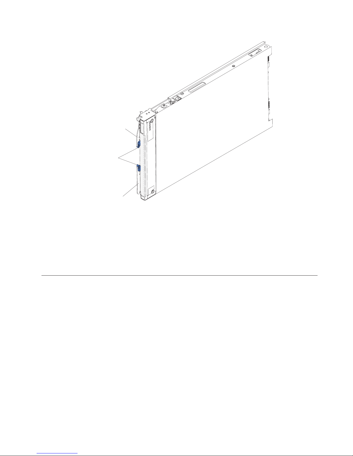
Release
handle
Release
buttons
Release
handle
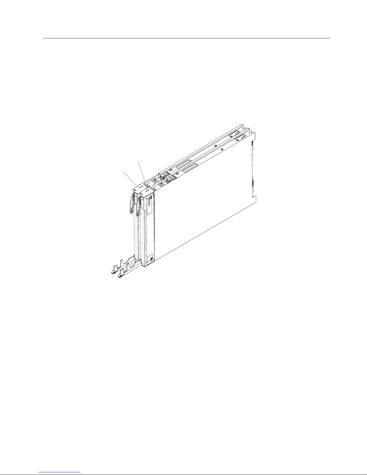
A set of blank labels for your blade server comes with the BladeCenter chassis.
When you install the blade server in the BladeCenter chassis, write identifying
information about the blade server on a label. Then place the label on the
BladeCenter chassis bezel. See the documentation for your BladeCenter chassis for
recommended label placement.
Important: Do not place the label on the blade server itself or in any way block
the ventilation holes on the blade server.
Related documentation
Use this information to identify and locate related blade server documentation.
This Installation and User's Guide contains general information about the blade
server, including how to install supported optional devices and how to configure
the blade server. The following documentation is also available:
v Problem Determination and Service Guide
This document contains information to help you solve problems yourself, and it
contains information for service technicians.
v Safety Information
This document contains translated caution and danger statements. Each caution
and danger statement that appears in the documentation has a number that you
can use to locate the corresponding statement in your language in the Safety
Information document.
v Warranty Information
This document contains information about the terms of the warranty.
v Environmental Notices and User Guide
This document contains translated environmental notices.
Chapter 1. Introduction 3
Page 14

v Integrated Management Module User's Guide
This document explains how to use the functions of the IMM that is installed in
an IBM server. The IMM works with IBM System x
systems-management capability for System x and BladeCenter servers.
v Advanced Management Module User's Guide
This document provides information about configuring the advanced
management module and managing components that are installed in an IBM
BladeCenter®chassis.
v Advanced Management Module Command-Line Interface Reference Guide
This document explains how to use the advanced management module
command-line interface (CLI) to directly access BladeCenter management
functions. The command-line interface also provides access to the text-console
command prompt on each blade server through a Serial over LAN (SOL)
connection.
v Advanced Management Module Messages Guide
This document provides a complete list of all non-device specific events and
recommended actions, sorted by event ID. Device-specific event information is
available in the Problem Determination and Service Guide.
In addition to the documentation in this library, be sure to review the Planning and
Installation Guide for your BladeCenter chassis for information to help you prepare
for system installation and configuration.
®
Server Firmware to provide
®
To check for updated documentation, complete the following steps.
1. Go to http://www.ibm.com/systems/support/.
2. Under Product support, click BladeCenter.
3. Under Popular links, click Publications lookup.
4. From the Product family menu, select BladeCenter HX5 .
You can also find documentation that is related to BladeCenter products at
http://publib.boulder.ibm.com/infocenter/bladectr/documentation/index.jsp.
The IBM Documentation CD
The IBM Documentation CD contains documentation for your blade server in
Portable Document Format (PDF). It includes the IBM Documentation Browser to
help you find information quickly.
You can run the IBM Documentation CD on any personal computer that meets the
hardware and software requirements.
Hardware and software requirements
Use this information to determine the minimum hardware and software
requirements for the blade server.
The IBM Documentation CD requires the following minimum hardware and
software:
v Microsoft Windows XP, Windows 2000, or Red Hat Enterprise Linux 5 Server
v 100 MHz microprocessor
v 32 MB of RAM
v Adobe Acrobat Reader 3.0 (or later) or xpdf, which comes with Linux operating
systems
4 IBM BladeCenter HX5 Type 7873, 7872, 1910, and 1909: Installation and User's Guide
Page 15

Using the Documentation Browser
Use these instructions to start the Documentation Browser.
Use the Documentation Browser to browse the contents of the CD, read brief
descriptions of the documents, and view documents, using Adobe Acrobat Reader
or xpdf. The Documentation Browser automatically detects the regional settings in
use in your system and displays the documents in the language for that region (if
available). If a document is not available in the language for that region, the
English-language version is displayed.
Use one of the following procedures to start the Documentation Browser:
v If Autostart is enabled, insert the CD into the CD drive. The Documentation
Browser starts automatically.
v If Autostart is disabled or is not enabled for all users, use one of the following
procedures:
– If you are using a Windows operating system, insert the CD into the CD or
DVD drive and click Start → Run.IntheOpen field, type
e:\win32.bat
where e is the drive letter of the CD or DVD drive, and click OK.
– If you are using Red Hat Linux, insert the CD into the CD or DVD drive;
then, run the following command from the /mnt/cdrom directory:
sh runlinux.sh
Select your blade server from the Product menu. The Available Topics list displays
all the documents for your blade server. Some documents might be in folders. A
plus sign (+) indicates each folder or document that has additional documents
under it. Click the plus sign to display the additional documents.
When you select a document, a description of the document is displayed under
Topic Description. To select more than one document, press and hold the Ctrl key
while you select the documents. Click View Book to view the selected document
or documents in Acrobat Reader or xpdf. If you selected more than one document,
all the selected documents are opened in Acrobat Reader or xpdf.
To search all the documents, type a word or word string in the Search field and
click Search. The documents in which the word or word string appears are listed
in order of the most occurrences. Click a document to view it. Press Ctrl+F to use
the Acrobat search function, or press Alt+F to use the xpdf search function within
the document.
Click Help for detailed information about using the Documentation Browser.
Chapter 1. Introduction 5
Page 16

Notices and statements in this document
Use this information to understand the most common documentation notices and
statements and how they are used.
The caution and danger statements in this document are also in the multilingual
Safety Information document, which is on the IBM Documentation CD. Each
statement is numbered for reference to the corresponding statement in the Safety
Information document.
The following notices and statements are used in this document:
v Note: These notices provide important tips, guidance, or advice.
v Important: These notices provide information or advice that might help you
avoid inconvenient or problem situations.
v Attention: These notices indicate possible damage to programs, devices, or data.
An attention notice is placed just before the instruction or situation in which
damage might occur.
v Caution: These statements indicate situations that can be potentially hazardous
to you. A caution statement is placed just before the description of a potentially
hazardous procedure step or situation.
v Danger: These statements indicate situations that can be potentially lethal or
hazardous to you. A danger statement is placed just before the description of a
potentially lethal or hazardous procedure step or situation.
Features and specifications
Use this table to view specific information about the blade server, such as blade
server hardware features and the dimensions of the blade server.
Notes:
1. Power, cooling, removable-media drives, external ports, and advanced systems
management are provided by the BladeCenter chassis.
2. The operating system in the blade server must provide USB support for the
blade server to recognize and use USB media drives and devices. The
BladeCenter chassis uses USB for internal communications with these devices.
The following table is a summary of the features and specifications of the
BladeCenter HX5 blade server.
6 IBM BladeCenter HX5 Type 7873, 7872, 1910, and 1909: Installation and User's Guide
Page 17

Table 1. Features and specifications
Microprocessor: Up to 2 multi-core
Intel Xeon processors.
Note: Use the Setup utility to
determine the type and speed of the
microprocessors in the blade server.
Memory:
v 16 dual inline memory module
(DIMM) connectors
v Type: Very Low Profile (VLP)
double-data rate (DDR3) DRAM.
Supports 2 GB, 4 GB, 8 GB, and 16
GB DIMMs with up to 256 GB of
total memory on the system board
If two BladeCenter HX5 blade servers
are assembled into a scalable blade
complex, up to 512 GB is available to
the scalable blade complex.
If the IBM MAX5 is installed:
v Supports up to 40 dual inline
memory module (DIMM)
connectors for up to 640 GB of total
memory.
Note: The BladeCenter HX5 blade
server supports memory sparing.
Integrated functions:
v Horizontal-compact-form-factor
(CFFh) expansion card interface
v Vertical-combination-I/O (CIOv)
expansion card interface
v Local service processor: integrated
management module (IMM) with
Intelligent Platform Management
Interface (IPMI) firmware
v Integrated Matrox G200eV video
controller
v Broadcom BCM5709S dual-port
Gigabit Ethernet controller
v Integrated keyboard/video/
mouse (cKVM) controller through
IMM
v Light path diagnostics
v RS-485 interface for
communication with the
management module
v Automatic server restart (ASR)
v USB 2.0 for communication with
cKVM and removable media
drives (an external USB port is not
supported)
v Serial over LAN (SOL)
v Wake on LAN (WOL)
v Redundant buses for
communication with keyboard,
mouse, and removable media
drives
Predictive Failure Analysis (PFA)
alerts:
v Microprocessors
v Memory
Electrical input: 12Vdc
Size:
Single BladeCenter HX5 blade
server:
v Height: 24.5 cm (9.7 in) (6U)
v Depth: 44.6 cm (17.6 in)
v Width: 2.9 cm (1.14 in)
v Maximum weight: 5.6 kg (12.38 lb)
2 BladeCenter HX5 blade servers
assembled into a scalable blade
complex:
v Height: 24.5 cm (9.7 in) (6U)
v Depth: 44.6 cm (17.6 in)
v Width: 5.8 cm (2.28 in)
v Maximum weight: 11.23 kg (24.76
lb)
Environment:
v Air temperature:
– Blade server on: 10°C to 35°C
(50°F to 95°F). Altitude:0mto
914.4 m (0 ft to 3000 ft)
– Blade server on: 10°C to 32°C
(50°F to 89.6°F). Altitude: 914.4 m
to 2133.6 m (3000 ft to 7000 ft)
– Blade server off: 10°C to 43°C
(50°F to 109.4°F). Altitude: 914.4
m to 2133.6 m (3000 ft to 7000 ft)
– Blade server shipping: -40°C to
60°C (-40°F to 140°F)
v Humidity:
– Blade server on: 8% to 80%
– Blade server off: 8% to 80%
– Blade server storage: 5% to 80%
– Blade server shipping: 5% to
100%
v Particulate contamination
Attention: Airborne particulates
and reactive gases acting alone or in
combination with other
environmental factors such as
humidity or temperature might pose
a risk to the server. For information
about the limits for particulates and
gases, see “Particulate
contamination” on page 122.
A BladeCenter HX5 blade server
combined with an IBM MAX5
expansion blade:
v Height: 24.5 cm (9.7 in) (6U)
v Depth: 44.6 cm (17.6 in)
v Width: 5.8 cm (2.28 in)
v Maximum weight: 9.5 kg (21.0 lb)
Chapter 1. Introduction 7
Page 18

What your blade server offers
Your blade server offers features, such as the integrated management module,
storage disk drive support, IBM®Systems Director, IBM Enterprise X-Architecture®,
microprocessor technology, integrated network support, I/O expansion, large
system-memory capacity, light path diagnostics LEDs, PCI Express
throttling.
v Integrated management module (IMM)
The integrated management module (IMM) combines service processor
functions, video controller, the remote presence, and blue-screen capture features
in a single chip. The IMM provides advanced service-processor control,
monitoring, and alerting function. If an environmental condition exceeds a
threshold or if a system component fails, the IMM lights LEDs to help you
diagnose the problem, records the error in the IMM event log, and alerts you to
the problem.
Optionally, the IMM also provides a virtual presence capability for remote server
management capabilities. The IMM provides remove server management
through industry-standard interfaces:
– Intelligent Platform Management Interface (IPMI) version 2.0
– Simple Network Management Protocol (SNMP) version 3.0
– Common Information Model (CIM)
– Web browser.
For more information, see Chapter 6, “Accessing the IMM,” on page 107.
v Dynamic System Analysis (DSA)
IBM Dynamic Systems Analysis (DSA) collects and analyses system information
to aid in diagnosing server problems. DSA collects the following information
about the server:
– Drive health information
– Event logs for ServeRAID controllers and service processors
– Hardware inventory, including PCI and USB information
– Installed applications and hot fixes
– Kernel modules
– Light path diagnostics status
– Network interface and settings
– Performance data and details about processes that are running
– RAID and controller configuration
– Service processor (integrated management module) status and configuration
– System configuration
– Vital product data and firmware information
DSA creates a DSA log, which is a chronologically ordered merge of the
system-event log (as the IPMI event log), the integrated management module
(IMM) chassis-event log (as the ASM event log), and the operating-system event
logs. You can send the DSA log as a file to IBM service or view the information
as a text file or HTML file.
For more information, see the Problem Determination and Service Guide.
v Hard disk drive support
The blade server supports up to two solid state drives (SSDs). You can
implement RAID 0 or RAID 1 for the SSDs.
v IBM ServerGuide Setup and Installation CD
®
, and power
8 IBM BladeCenter HX5 Type 7873, 7872, 1910, and 1909: Installation and User's Guide
Page 19

The ServerGuide Setup and Installation CD, which you can download from the
Web, provides programs to help you set up the server and install a Windows
operating system. The ServerGuide program detects installed optional hardware
devices and provides the correct configuration programs and device drivers. For
more information, see “Using the ServerGuide Setup and Installation CD” on
page 103.
v IBM Systems Director
IBM Systems Director is a platform-management foundation that streamlines the
way you manage physical and virtual systems in a heterogeneous environment.
By using industry standards, IBM Systems Director supports multiple operating
systems and virtualization technologies for IBM and non-IBM x86 platforms. For
more information, see http://publib.boulder.ibm.com/infocenter/director/
v6r2x/index.jsp.
v IBM Enterprise X-Architecture
IBM Enterprise X-Architecture technology combines proven, innovative IBM
designs to make your x86-processor-based blade server powerful, scalable, and
reliable. For more information, see http://www.ibm.com/systems/x/hardware/
enterprise/xarchitecture.html.
v Microprocessor technology
The blade server supports up to two multi-core Intel Xeon microprocessors. For
more information about supported microprocessors and their part numbers, see
the Problem Determination and Service Guide.
Note: The optional microprocessors that IBM supports are limited by the
capacity and capability of the server. Any microprocessors that you install must
have the same specifications as the microprocessors that came with the servers.
v Integrated network support
All blade server models come with an integrated Broadcom dual-port Gigabit
Ethernet controller. The controller supports connections to a 10 Mbps, 100 Mbps,
or 1000 Mbps network through an Ethernet-compatible switch module in the
BladeCenter chassis. The controller also supports Wake on LAN
®
technology.
v I/O expansion
The blade server has connectors on the system board for optional expansion
cards for adding more network communication capabilities to the blade server.
v Large system-memory capacity
The blade server system board supports up to 256 GB of system memory. The
memory controller provides support for up to 16 industry-standard registered
ECC DDR3 on Very Low Profile (VLP) form factor DIMMs installed on the
system board. For the most current list of supported DIMMs, see the
ServerProven
®
list at http://www.ibm.com/servers/eserver/serverproven/
compat/us/eserver.html.
Note: If two BladeCenter HX5 blade servers are assembled into a scalable blade
complex, up to 512 GB of system memory is available to the scalable blade
complex.
v Server expansion
You can combine two blade servers together to form a scalable blade complex.
Through the advanced management module Web interface, you can then
configure the scalable blade complex to function as a single hardware partition,
which is single server with up to four multi-core microprocessors and up to 512
GB of system memory.
Chapter 1. Introduction 9
Page 20

Combining two blade servers into a scalable blade complex provides you with
implementation flexibility through FlexNode partitioning. Through the advanced
management module, you can implement the scalable blade complex as a single
server or as two independent servers without changing the physical setup of the
blade servers. For more information about scalable blade complexes and
FlexNode partitioning, see “Working with a scalable blade complex” on page 13.
v Light path diagnostics
Light path diagnostics provides light-emitting diodes (LEDs) to help you
diagnose problems. For more information, see the Problem Determination and
Service Guide.
In addition, scalability indicators are available through the front bezel. These
indicators enable you to tell whether BladeCenter HX5 blade servers are
operating independently or as a single hardware partition.
v PCI Express
PCI Express is a serial interface that is used for chip-to-chip interconnect and
expansion adapter interconnect. With the blade expansion connector, you can
add optional I/O and storage devices.
v Power throttling
Each blade server is powered by two Enterprise Voltage Regulator-Down
(EVRD) 11.0 voltage regulators. By enforcing a power policy known as
power-domain oversubscription, the BladeCenter chassis can share the power
load between two power modules to ensure sufficient power for each device in
the BladeCenter chassis. This policy is enforced when the initial power is
applied to the BladeCenter chassis or when a blade server is inserted into the
BladeCenter chassis.
The following settings for this policy are available:
– Power module redundancy
– Power module redundancy with blade throttling allowed
– Basic power management
You can configure and monitor the power environment by using the advanced
management module. For more information about configuring and using power
throttling, see the Advanced Management Module User's Guide (available at
http://publib.boulder.ibm.com/infocenter/bladectr/documentation/index.jsp)
or http://www.ibm.com/systems/support/.
Reliability, availability, and serviceability features
Three of the most important features in server design are reliability, availability,
and serviceability (RAS). These RAS features help to ensure the integrity of the
data that is stored in the blade server, the availability of the blade server when you
need it, and the ease with which you can diagnose and correct problems.
The blade server has the following RAS features:
v Customer upgrade of flash ROM-resident code and diagnostics
v Power policy 24-hour support center
v Vital product data (VPD) on memory
v Processor presence detection
v Advanced Configuration and Power Interface (ACPI)
v Automatic server restart (ASR)
v Built-in diagnostics using DSA Preboot, which is stored in integrated USB
memory.
v Built in monitoring for temperature, voltage, and hard disk drives
10 IBM BladeCenter HX5 Type 7873, 7872, 1910, and 1909: Installation and User's Guide
Page 21

v Customer support center 24 hours per day, 7 days a week.
v Customer-upgradeable Unified Extensible Firmware Interface (UEFI) code and
diagnostics
v ECC protection on the L2 cache
v Error codes and messages
v Integrated management module (IMM)
v Light path diagnostics
v Memory parity testing
v Registered ECC DDR3 memory
v Microprocessor built-in self-test (BIST) during power-on self-test (POST)
v Microprocessor serial number access
v PCI PMI 2.2
v PCI Express 1.0a
v POST
v ROM-resident diagnostics
v Service processor that communicates with the advanced management module to
enable remote blade server management
v System-error logging
v Wake on LAN capability
v Wake on PCI (PME) capability
v Wake on USB 2.0 capability
IBM Systems Director
1
IBM Systems Director is a platform-management foundation that streamlines the
way you manage physical and virtual systems in a heterogeneous environment.
By using industry standards, IBM Systems Director supports multiple operating
systems and virtualization technologies in IBM and non-IBM x86 platforms.
Through a single user interface, IBM Systems Director provides consistent views
for viewing managed systems, determining how these systems relate to one
another, and identifying their statuses, helping to correlate technical resources with
business needs. A set of common tasks that are included with IBM Systems
Director provides many of the core capabilities that are required for basic
management, which means instance business value. These common tasks include
discovery, inventory, configuration, system health, monitoring, updates, event
notification, and automation for managed systems.
The IBM Systems Director web and command-line interfaces provide a consistent
interface that is focused on driving these common tasks and capabilities:
v Discovering, navigating, and visualizing systems on the network with the
detailed inventory and relationships to the other network resources
v Notifying users of problems that occur on systems and the ability to isolate
sources of the problems
v Notifying users when systems need updates and distributing and installing
updates on a schedule
v Analyzing real-time data for systems and setting critical thresholds that notify
the administrator of emerging problems
v Configuring settings of a single system and creating a configuration plan that
can apply those settings to multiple systems
1. Service availability varies by country. Response time varies depending on the number and nature of incoming calls.
Chapter 1. Introduction
11
Page 22

v Updating installed plug-ins to add new features and functions to the base
capabilities
v Managing the life cycles of virtual resources
For more information about IBM Systems Director, see the documentation at
http://publib.boulder.ibm.com/infocenter/director/v6r2x/index.jsp, and the IBM
xSeries
®
Systems Management website at http://www.ibm.com/systems/
management/, which presents an overview of IBM Systems Management and IBM
Systems Director.
Major components of the blade server
Use this information to locate the major components on the blade server. The
major components of the blade server include field replaceable units (FRUs),
customer replaceable units (CRUs), and optional devices.
The following illustration shows the major components of the blade server.
Cover
SSD
expansion
card
DIMM
Scaling
card filler
Expansion
cards
Operator
control
panel
Heat sink
Battery cover
Microprocessor
heat sink filler
Microprocessor
Battery
Embedded
hypervisor
interposer
Front
access
cover
12 IBM BladeCenter HX5 Type 7873, 7872, 1910, and 1909: Installation and User's Guide
Page 23
Working with a scalable blade complex
You can assemble two BladeCenter HX5 blade servers together to create a scalable
blade complex.
A scalable blade complex supports the following implementation modes:
v Single partition. The complex functions as a single server that contains up to
four multi-core processors and up to 32 DIMMs. When the complex is
implemented as a single hardware partition, the leftmost blade server (as
installed in a BladeCenter chassis) is called the primary blade server. The blade
server on the right is called the secondary blade server.
Secondary
Primary
blade
server
blade
server
v Multiple partitions (independent partitions). The blade servers are combined
into a scalable blade complex, but each of the blade servers is set up as a single
partition.
v Stand-alone mode. The blade servers operate independently.
Important: If you install the primary blade server of a scalable blade complex in
blade server bay 7 of a BladeCenter H Type 8852 chassis, the secondary blade
server is installed in blade server bay 8. The primary blade server receives power
from power domain 1 of the chassis and the secondary blade server receives power
from power domain 2 of the chassis. The following situations can occur if there is a
power loss to either power domain, depending on how the scalable blade complex
is implemented:
v If the scalable blade complex is implemented in single partition mode, a loss of
power to power domain 1 or power domain 2 results in both blade servers in
the scalable blade complex going down.
v If the scalable blade complex is implemented in stand-alone mode, a loss of
power to power domain 1 results in the entire scalable blade complex going
down. A loss of power to power domain 2 results in the blade server installed in
blade server bay 8 going down, but the blade server installed in blade server
bay 7 continues to function.
Chapter 1. Introduction 13
Page 24

With FlexNode processing, you can toggle between single partition mode and
stand-alone mode without having to modify the physical setup of the blade
servers. To toggle between modes, use the advanced management module Web
interface.
For example, assume that you have created a scalable blade complex and defined
that complex as a single partition through the advanced management module Web
interface:
v You can toggle the scalable blade complex to stand-alone mode through the Web
interface. In stand-alone mode, you can install a different operating system on
each blade server and run different applications on each blade server.
v You can then toggle the blade server complex back to a single partition and run
applications that take advantage to up to 4 processors and 32 DIMMs. The
operating system that is in use is the operating system of the primary blade
server.
v Later, you can toggle the complex back to stand-alone mode again to gain access
to the operating system on the secondary blade server.
Single partition mode considerations
The following considerations apply to the blade servers in a scalable blade
complex that operates as a single hardware partition:
v All UEFI settings (set through the Setup utility) should be the same on both
blade servers. If they are not, the settings that are defined for the primary blade
server replace the UEFI settings on the secondary server.
Note: When you upgrade the firmware for the blade servers operating in single
partition mode, you only have to upgrade the primary blade server. The
firmware on the secondary blade server is automatically updated. See “Using
the Setup utility” on page 72 for more information about the Setup utility.
v The primary blade server has access to the SSDs on the secondary blade server.
However, the SSDs on the primary blade server cannot be combined with the
SSDs on the secondary blade server to form a single RAID array. RAID arrays
can be formed only using the SSDs within a blade server.
v The primary blade server has access to any I/O expansion cards that are
installed in the secondary blade server. However, the I/O expansion cards in the
secondary blade server cannot be used for a Serial Over LAN connection.
v The primary blade server has access to any expansion blades that are installed
on the secondary blade server.
Important: An expansion blade installed on the secondary blade server cannot
be used for a Serial Over LAN connection.
v If you press the power button on one blade server, both blade servers in the
partition either power up or power down, depending on the state of the blade
servers when you press the power button.
14 IBM BladeCenter HX5 Type 7873, 7872, 1910, and 1909: Installation and User's Guide
Page 25

Chapter 2. Power, controls, and indicators
Use this information to view power features, turn on and turn off the blade server,
and view the functions of the controls and indicators.
Turning on the blade server
After you connect the blade server to power through the BladeCenter chassis, the
blade server can be started in any of the following ways.
v You can press the power button on the front of the blade server (see “Blade
server controls and LEDs” on page 16) to start the blade server. The power
button works only if local power control is enabled for the blade server. Local
power control is enabled and disabled through the advanced management
module Web interface.
Notes:
1. Wait until the power LED on the blade server flashes slowly before you press
the power button. While the service processor in the blade server is
initializing and synchronizing with the advanced management module, the
power-on LED flashes rapidly, and the power-control button on the blade
server does not respond. This process can take approximately 90 seconds
after the blade server has been installed.
2. While the blade server is starting, the power LED on the front of the blade
server is lit and does not flash. See “Blade server controls and LEDs” on
page 16 for the power LED states.
v If a power failure occurs, the BladeCenter chassis and the blade server can be
configured through the advanced management module Web interface to start
automatically when power is restored.
v You can turn on the blade server through the advanced management module
Web interface. For more information about the advanced management module
Web interface, see the IBM BladeCenter Advanced Management Module: User's
Guide.
v You can turn on the blade server through the Wake on LAN feature. The blade
server must be connected to power (the power-on LED is flashing slowly), the
blade server must be communicating with the advanced management module,
the operating system must support the Wake on LAN feature, and the Wake on
LAN feature must be enabled through the advanced management module
interface.
Note: Procedure to enable the Wake on LAN feature varies depending on the
network device. Refer to the documentation that is provided for your network
device for more information.
Turning off the blade server
When you turn off the blade server, it is still connected to power through the
BladeCenter chassis. The blade server can respond to requests from the service
processor, such as a remote request to turn on the blade server. To remove all
power from the blade server, you must remove it from the BladeCenter chassis.
© Copyright IBM Corp. 2011 15
Page 26
Before you turn off the blade server, shut down the operating system. See the
operating-system documentation for information about shutting down the
operating system.
The blade server can be turned off in any of the following ways:
v You can press the power button on the blade server (see “Blade server controls
and LEDs”). Pressing the button starts an orderly shutdown of the operating
system, if this feature is supported by the operating system.
v If the operating system stops functioning, you can press and hold the power
button for more than 4 seconds to turn off the blade server.
Attention: Pressing the button for 4 seconds forces the operating system to
shut down immediately. Data loss is possible.
v You can turn off the blade server through the advanced management module
web interface. For more information about the advanced management module
web interface, see the IBM BladeCenter Advanced Management Module: User's
Guide.
Blade server controls and LEDs
Use this information for details about the controls and LEDs on the blade server
and IBM MAX5 expansion blade.
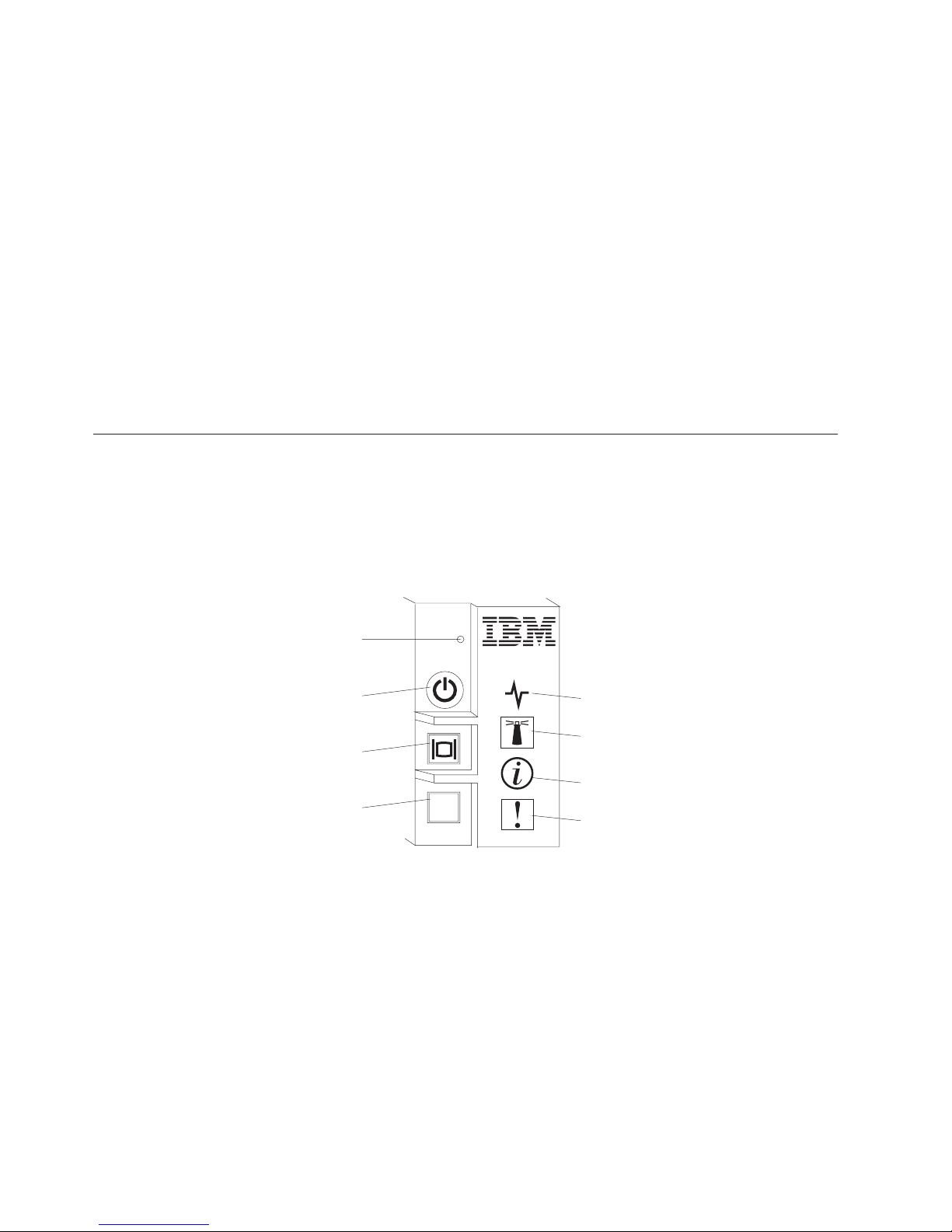
The following illustration identifies the buttons and LEDs on the blade server
control panel.
NMI button
Power button / LED
KVM select
button / LED
Media tray select
button / LED
NMI button (recessed)
The nonmaskable interrupt (NMI) dumps the partition. Use this recessed
button only as directed by IBM Support.
Note: You can also send an NMI event to the selected blade server
remotely using the AMM. Refer to the BladeCenter Advanced Management
Module User's Guide for information pertaining to the proper installation
and configuration of Java, operating systems, and browsers that are
supported for remote access.
Power button/LED
MT
Activity LED
Location LED
Information LED
Fault LED
When the blade server has power, press this button to turn on or turn off
the blade server.
16 IBM BladeCenter HX5 Type 7873, 7872, 1910, and 1909: Installation and User's Guide
Page 27

Note: The power button works only if local power control is enabled for
the blade server. Local power control is enabled and disabled through the
advanced management module web interface.
After the blade server is removed from the chassis, press this button to
activate the system board LEDs (light path diagnostics). See the Problem
Determination and Service Guide for more information.
This button is also the power LED. This green LED indicates the power
status of the blade server:
v Flashing rapidly: The LED flashes rapidly for one of the following
reasons:
– The blade server has been installed in a chassis. When you install the
blade server, the LED flashes rapidly for up to 90 seconds while the
integrated management module (IMM) on the blade server is
initializing and synchronizing with the advanced management
module.
– The blade server does not have power permissions assigned to it
through the advanced management module.
– The BladeCenter chassis does not have enough power to turn on the
blade server.
– The IMM on the blade server is not communicating with the
advanced management module.
v Flashing slowly: The blade server has power and is ready to be turned
on.
v Lit continuously: The blade server has power and is turned on.
When the blade server is on, pressing this button causes an orderly
shutdown of the blade server so that it is safe to remove. This includes
shutting down the operating system (if possible) and removing power
from the blade server.
Note: If you press the power button on the blade server that is part of a
scalable blade complex running as a single partition, both blade servers in
the partition power on or shut down.
If an operating system is running, you might have to press the button for
approximately 4 seconds to initiate the shutdown.
Attention: Pressing the button for 4 seconds forces the operating system
to shut down immediately. Data loss is possible.
KVM select button/LED
Press this button to associate the shared BladeCenter chassis keyboard,
video, and mouse (KVM) ports with the blade server. The LED on this
button flashes while the request is being processed and then is lit when the
ownership of the keyboard, video, and mouse has been transferred to the
blade server. It can take approximately 20 seconds to switch the keyboard,
video, and mouse control to the blade server.
Using a keyboard that is directly attached to the advanced management
module, you can press keyboard keys in the following sequence to switch
KVM control between blade servers instead of using the KVM select
button:
NumLock NumLock blade_server_number Enter
Chapter 2. Power, controls, and indicators 17
Page 28

Where blade_server_number is the two-digit number of the blade server
bay in which the blade server is installed. A blade server that occupies
more than one blade server bay is identified by the lowest bay number
that it occupies.
If there is no response when you press the KVM select button, you can use
the advanced management module web interface to determine whether
local control has been disabled on the blade server. See the IBM BladeCenter
Advanced Management Module: User's Guide for more information.
Notes:
1. The operating system in the blade server must provide USB support for
the blade server to recognize and use the keyboard and mouse, even if
the keyboard and mouse have PS/2-style connectors.
2. If you install a supported Microsoft Windows operating system on the
blade server while it is not the current owner of the keyboard, video,
and mouse, a delay of up to 1 minute occurs the first time that you
switch the keyboard, video, and mouse to the blade server. All
subsequent switching takes place in the normal KVM switching time
frame (up to 20 seconds).
Media tray select button/LED
Press this button to associate the shared BladeCenter chassis media tray
(removable-media drives) with the blade server. The LED on the button
flashes while the request is being processed and then is lit when the
ownership of the media tray has been transferred to the blade server. It can
take approximately 20 seconds for the operating system in the blade server
to recognize the media tray.
If there is no response when you press the media-tray select button, you
can use the advanced management module web interface to determine
whether local control has been disabled on the blade server.
Note: The operating system in the blade server must provide USB support
for the blade server to recognize and use the removable-media drives.
Activity LED
When this green LED is lit (flashing), it indicates that there is activity on
the network or external storage device.
Location LED
The system administrator can remotely turn on this blue LED to aid in
visually locating the blade server. When this LED is lit, the location LED
on the BladeCenter chassis is also lit. The location LED can be turned on
and off through the advanced management module web interface or
through IBM Systems Director. For more information about the advanced
management module web interface, see the IBM BladeCenter Advanced
Management Module: User's Guide. For more information about IBM Systems
Director, see the documentation, which is available at http://
publib.boulder.ibm.com/infocenter/director/v6r2x/index.jsp.
Information LED
When this amber LED is lit, it indicates that an Automatic BIOS recovery
(ABR) has occurred. The blade server starts up using the backup UEFI
image. See the Problem Determination and Service Guide
The information LED can be turned off through the advanced management
module CLI, SNMP, or web interfaces or through IBM
For more information about the advanced management module web
18 IBM BladeCenter HX5 Type 7873, 7872, 1910, and 1909: Installation and User's Guide
®
Systems Director.
Page 29

interface, see the IBM BladeCenter Advanced Management Module: User's
Guide. For more information about IBM Systems Director, see the
documentation, which is available at http://publib.boulder.ibm.com/
infocenter/director/v6r2x/index.jsp.
Fault LED
When this amber LED is lit, it indicates that a system error has occurred in
the blade server. In addition, the fault LED on the chassis system LED
panel is lit. See the Problem Determination and Service Guide
The fault LED turns off only after the error is corrected.
Note: When the fault LED turns off, you should also clear the IMM event
log. Use the Setup utility to clear the IMM event log.
IBM MAX5 LEDs
When there is a fault on the IBM MAX5 expansion blade, the front bezel of the
IBM MAX5 expansion blade will appear to have an orange glow. You can press the
light path button on the system board of the IBM MAX5 expansion blade to
determine which LEDs are lit.
Note: If there is an orange glow, it will be referred to as MEU (Memory Expansion
Unit) Fault in the system event log.
The following LEDs are available on the IBM MAX5 expansion blade light path
diagnostic panel:
See Light Path Below (LP1)
This amber LED indicates that there is a problem with the BladeCenter
HX5 to which the IBM MAX5 expansion blade was attached. If this LED is
lit, complete the following steps:
1. Remove the IBM MAX5 expansion blade (see “Removing an IBM
MAX5” on page 30).
2. Press the power button on the BladeCenter HX5 blade server to
determine which LEDs are lit on the blade server.
The See Light Path Below (LP1) LED is referred to as MEU Look Below in
the system event log.
System Board (S BRD)
This amber LED indicates that there is a problem with the system board. If
this amber LED is lit, complete the following steps:
1. Install the IBM MAX5 (see “Installing an IBM MAX5” on page 62).
2. Install the BladeCenter HX5 in the chassis (see “Installing a blade
server in a BladeCenter chassis” on page 68).
3. Restart the blade server.
4. If the problem remains, replace the system board on the IBM MAX5
(see the Problem Determination and Service Guide for instructions).
The System Board (S BRD) LED is referred to as MEU Error in the system
event log.
Light path power (LP2)
This amber LED indicates that one or more LEDs are lit on the IBM MAX5
system board. .
Chapter 2. Power, controls, and indicators 19
Page 30
The Light path power (LP2) LED is referred to as MEU LED Power in the
system event log.
See the Problem Determination and Service Guide
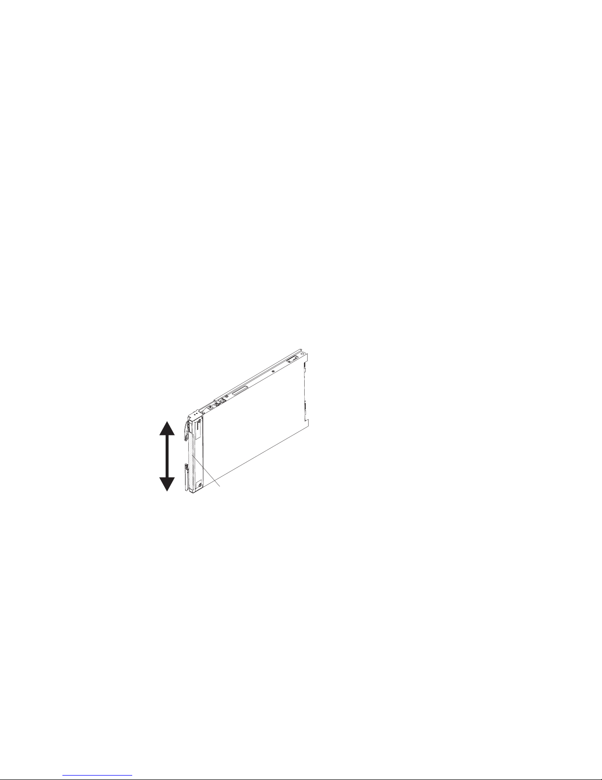
Scalability indicators
The BladeCenter HX5 blade server provides scalability indicators, which are
viewable through the front bezel of the blade server when it is installed in a
BladeCenter chassis. The scalability indicators remain lit until the blade server is
started.
The BladeCenter HX5 blade server can be deployed as a stand-alone blade server.
It can also be combined with another BladeCenter HX5 blade server to form a
scalable blade complex. When two BladeCenter HX5 blade servers are combined
into a scalable blade complex, you can specify that they operate as a single
hardware partition or operate in stand-alone mode.
The scalability indicators show whether a BladeCenter HX5 blade server is a
stand-alone blade server or a node in a scalable blade complex operating as a
single hardware partition.
When a BladeCenter HX5 blade server is a stand-alone blade server, the scalability
indicators continually move up and down the front of the bezel.
When a BladeCenter HX5 blade server is part of the scalable blade complex
operating in single partition mode, the scalability indicators move up the first
blade server, cross over to the second blade server, and then move down the
second blade server.
Note: If you have set up a scalable blade complex in single partition mode but
when you start the blade servers, the scalability indicators for each blade server
seem to be operating independently, there might be a problem with the
configuration of the scalable blade complex.
20 IBM BladeCenter HX5 Type 7873, 7872, 1910, and 1909: Installation and User's Guide
LEDs
Page 31

LEDs
Blade server connectors - BladeCenter HX5
Use this information to locate blade server system board components and
connectors for optional devices.
The following illustration shows the system board components, including
connectors for user-installable optional devices, in the blade server.
Powe r
Scaling card
connector
Control panel
connector
Microprocessor 1
Microprocessor 2
sharing
connector
ALTERNATELY
TIGHTEN
SCREWS
DIMMs
1 - 8
I/O expansion
connector
(SSD)
I/O expansion
connector (CIOv)
Note: The optional SSD expansion card is installed in the I/O expansion connector
(SSD).
Blade server connectors - IBM MAX5
Use this information to locate the IBM MAX5 expansion blade connectors.
The following illustration shows the system board components, including
connectors for user-installable optional devices, in the IBM MAX5 expansion blade.
Battery
Hypervisor
inteposer
connector
DIMMs
9 - 16
Blade expansion
connector
Chapter 2. Power, controls, and indicators 21
Page 32

Input/output connectors and devices
The input/output connectors that are available to the blade server are supplied by
the BladeCenter chassis. See the documentation that comes with the BladeCenter
chassis for information about the input/output connectors.
The blade server has two selection buttons on the control panel: the media tray
select button and the keyboard/video/mouse select button. See “Blade server
controls and LEDs” on page 16 for information about these buttons and their
functions.
The Ethernet controllers on the blade server communicate with the network
through the Ethernet-compatible I/O modules in the BladeCenter chassis. Network
signals to and from the blade server or any expansion cards are automatically
routed to a same-network-interface I/O module through circuitry in the
BladeCenter chassis.
22 IBM BladeCenter HX5 Type 7873, 7872, 1910, and 1909: Installation and User's Guide
Page 33

Chapter 3. Installing optional devices
Use this information for instructions about installing optional hardware devices in
the blade server and assembling blade servers into a scalable blade complex. Some
device-removal instructions are provided in case you have to remove one device to
install another.
Note: If you are installing devices in a scalable blade complex, remember to install
them in both BladeCenter HX5 blade servers in the complex.
Installation guidelines
Use these guidelines before you install the blade server or optional devices.
v Before you begin, read “Safety” on page v and “Handling static-sensitive
devices” on page 24. This information helps you work safely.
v When you install your new blade server, take the opportunity to download and
apply the most recent firmware updates. This step helps ensure that any known
issues are addressed and that your blade server is ready to function at
maximum levels of performance.
v Observe good housekeeping in the area where you are working. Place removed
covers and other parts in a safe place.
v Back up all important data before you make changes to disk drives.
v Before you remove a blade server from the BladeCenter chassis, you must shut
down the operating system and turn off the blade server. You do not need to
shut down the chassis itself.
v Blue on a component indicates touch points, where you can grip the component
to remove it from or install it in the blade server, open or close a latch, and so
on.
v For a list of supported optional devices for the blade server, see
http://www.ibm.com/servers/eserver/serverproven/compat/us/eserver.html .
System reliability guidelines
Use these guidelines to ensure that the blade server meets the proper cooling and
system reliability requirements.
v To ensure proper cooling, do not operate the BladeCenter chassis without a
blade server or blade filler installed in each blade server bay. See the
documentation for your BladeCenter chassis for additional information.
v Each microprocessor socket always contains either a microprocessor dust cover
and heat sink filler or a microprocessor and heat sink. If the blade server has
only one microprocessor, it must be installed in microprocessor socket 1.
v Make sure that the ventilation holes on the blade server are not blocked.
v The blade server battery must be operational. If the battery becomes defective,
replace it immediately. For instructions, see the Problem Determination and Service
Guide.
© Copyright IBM Corp. 2011 23
Page 34

Handling static-sensitive devices
To reduce the possibility of damage from electrostatic discharge, observe these
precautions.
Attention: Static electricity can damage the blade server and other electronic
devices. To avoid damage, keep static-sensitive devices in their static-protective
packages until you are ready to install them.
v When you work on a BladeCenter chassis that has an electrostatic discharge
(ESD) connector, use a wrist strap, especially when you handle modules,
optional devices, or blade servers. To work correctly, the wrist strap must have a
good contact at both ends (touching your skin at one end and firmly connected
to the ESD connector on the front or back of the BladeCenter chassis).
v Limit your movement. Movement can cause static electricity to build up around
you.
v Handle the device carefully, holding it by its edges or its frame.
v Do not touch solder joints, pins, or exposed circuitry.
v Do not leave the device where others can handle and damage it.
v While the device is still in its static-protective package, touch it to an unpainted
metal part of the BladeCenter chassis or any unpainted metal surface on any
other grounded rack component in the rack in which you are installing the
device for at least 2 seconds. This drains static electricity from the package and
from your body.
v Remove the device from its package and install it directly into the blade server
without setting down the device. If it is necessary to set down the device, put it
back into its static-protective package. Do not place the device on the blade
server cover or on a metal surface.
v Take additional care when you handle devices during cold weather. Heating
reduces indoor humidity and increases static electricity.
Removing the blade server from the BladeCenter chassis
Use these instructions to remove a BladeCenter HX5 blade server or a scalable
blade complex from a BladeCenter chassis.
The following illustration shows how to remove a BladeCenter HX5 blade server
from a chassis.
24 IBM BladeCenter HX5 Type 7873, 7872, 1910, and 1909: Installation and User's Guide
Page 35

Attention:
v To maintain proper system cooling, do not operate the BladeCenter chassis
without a blade server or filler module installed in each blade server bay.
v When you remove the blade server, note the blade server bay number.
Reinstalling a blade server into a different blade server bay from the one it was
removed from can have unintended consequences. Some configuration
information and update options are established according to blade server bay
number. If you reinstall the blade server into a different bay, you might need to
reconfigure the blade server.
To remove a BladeCenter HX5 blade server or scalable blade complex, complete
the following steps:
1. Before you begin, read “Safety” on page v and “Installation guidelines” on
page 23.
2. If the blade server is operating, shut down the operating system.
3. Press the power button to turn off the blade server (see “Turning off the blade
server” on page 15 for more information).
Note: If the blade server is part of a scalable blade complex operating in single
partition mode, pressing the power button on one blade server causes both
blade servers to shut down.
4. Open the two release handles as shown in the illustration. The blade server
moves out of the blade server bay approximately 0.6 cm (0.25 inch).
5. Pull the blade server out of the bay.
6. Install either a blade filler or another blade server in the blade server bay
within 1 minute.
Removing the blade server cover
Use these instructions to open and remove the cover from a blade server or from
the topmost blade server in a scalable blade complex.
To open and remove the blade server cover, complete the following steps.
1. Before you begin, read “Safety” on page v and “Installation guidelines” on
page 23.
2. Carefully lay the blade server on a flat, static-protective surface, orienting the
blade server with the bezel pointing toward you.
3. Press the blade server cover release on each side of the blade server, topmost
blade server in a scalable blade complex, or expansion unit, and lift the cover
away from the blade server, as shown in the following illustration.
Chapter 3. Installing optional devices 25
Page 36

Blade server
cover
Cover
pins
Blade server
cover release
4. Lay the cover flat or store it for future use.
Statement 12
CAUTION:
The following label indicates a hot surface nearby.
Statement 21
CAUTION:
Hazardous energy is present when the blade server is connected to the power
source. Always replace the blade cover before installing the blade server.
Disassembling a scalable blade complex
If the scalable blade complex came preassembled, you must disassemble it to add
components to each of the blade servers in the scalable blade complex.
Note: This procedure assumes that you are disassembling a scalable blade complex
to install components in each of the blade servers but that you will assemble the
blade server back into a scalable blade complex. If you are disassembling the
scalable blade complex to use the blade servers as independent, stand-alone blade
servers, see the Problem Determination and Service Guide.
26 IBM BladeCenter HX5 Type 7873, 7872, 1910, and 1909: Installation and User's Guide
Page 37

To disassemble a scalable blade complex, complete the following steps.
1. Before you begin, read “Safety” on page v and “Installation guidelines” on
page 23.
2. Remove the cover from the topmost blade server (see “Removing the blade
server cover” on page 25 for instructions).
3. If a blade expansion unit is installed, remove it (see “Removing an expansion
unit” on page 32).
4. Stand the blade servers upright on a clean, flat work surface, with the 2-node
scalability card facing up.
5. Release the lower handles (rotate the lower handles down) to allow the blade
servers to sit flat on the work surface
6. Remove the 2-node scalability card (see “Removing the 2-node scalability card”
on page 28 for instructions).
7. Press the blade server cover release on each side of the blade server and lift the
topmost blade server from the bottom blade server as shown in the following
illustration.
Secondary
BladeCenter HX5
blade server
Blade server
cover release
Blade server
cover release
Chapter 3. Installing optional devices 27
Page 38

Removing the 2-node scalability card
Use this information to remove the 2-node scalability card from a blade server.
To remove the 2-node scalability card, complete the following steps:
1. Before you begin, read “Safety” on page v and “Installation guidelines” on
page 23.
2. Loosen each screw on the 2-node scalability card, using the provided 3/16" hex
driver. Alternate the loosening of each screw until both screws are removed.
3. Lift the 2-node scalability card off both blade servers and store the card in a
safe place.
Alignment
pins
Alignment
pins
Note: When you remove the 2-node scalability card, the BladeCenter HX5
blade servers are no longer scaled; each blade server operates independently in
a chassis.
28 IBM BladeCenter HX5 Type 7873, 7872, 1910, and 1909: Installation and User's Guide
Page 39

Removing the IBM MAX5 1-node Scalability card
Use this information to remove the IBM MAX5 1-node scalability card from a blade
server.
To remove the IBM MAX5 1-node scalability card, complete the following steps.
1. Before you begin, read “Safety” on page v and “Installation guidelines” on
page 23.
2. Loosen each screw on the 1-node scalability card, using the provided 3/16" hex
driver. Alternate the loosening of each screw until both screws are removed.
3. Lift the 1-node scalability card off of the blade server and expansion blade and
store the card in a safe place.
Chapter 3. Installing optional devices 29
Page 40

Removing an IBM MAX5
Use these instructions to remove an IBM MAX5.
To remove an IBM MAX5, complete the following steps:
IBM MAX5
Blade server
cover release
Upper
ridge
Powe r
jumper
Blade server
cover release
1. Before you begin, read “Safety” on page v and “Installation guidelines” on
page 23.
2. Carefully lay the blade server on a flat, static-protective surface.
3. Remove the IBM MAX5 1-node scalability card (see “Removing the IBM MAX5
1-node Scalability card” on page 29 for instructions).
4. Remove the IBM MAX5:
a. Press the blade server cover release on each side of the blade server and lift
the IBM MAX5 from the blade server.
b. Rotate the IBM MAX5 open; then, lift the IBM MAX5 from the blade server.
5. Complete the following steps if you are not going to install another IBM MAX5
expansion blade:
Note: To use a BladeCenter HX5 blade server that has tall heat sinks, you must
install another IBM MAX5 expansion blade.
a. Locate the power sharing connector on the BladeCenter HX5 blade server
and install the power sharing cover (see “Blade server connectors BladeCenter HX5” on page 21).
b. Remove the EMC gasket from the upper ridge of the “Blade server
connectors - BladeCenter HX5” on page 21 blade server if one is installed.
30 IBM BladeCenter HX5 Type 7873, 7872, 1910, and 1909: Installation and User's Guide
Page 41

Installing an expansion unit
Use these instructions to install an expansion unit or for the topmost blade server
in a scalable blade complex.
Attention: You cannot insert the blade server into the BladeCenter chassis until
the cover is installed and closed. Do not attempt to override this protection.
Statement 21
CAUTION:
Hazardous energy is present when the blade server is connected to the power
source. Always replace the blade cover before installing the blade server.
Cover
Pins
Blade server
cover release
Blade server
cover release
To install and close the blade server cover, complete the following steps:
1. Before you begin, read “Safety” on page v and “Installation guidelines” on
page 23.
2. Carefully lay the blade server on a flat, static-protective surface, orienting the
blade server with the bezel pointing toward you.
3. Locate the blade expansion connector and remove the cover if one is installed
(see “Blade server connectors - BladeCenter HX5” on page 21).
4. Touch the static-protective package that contains the optional expansion unit to
any unpainted metal surface on the BladeCenter unit or any unpainted metal
surface on any other grounded rack component; then, remove the optional
expansion unit from the package.
5. Orient the optional expansion unit as shown in the illustration.
6. Lower the expansion unit so that the slots at the rear slide down onto the cover
pins at the rear of the blade server; then, pivot the expansion unit down onto
the blade server.
7. If the expansion unit has a cover already installed, remove it (see Removing the
blade server cover).
Chapter 3. Installing optional devices 31
Page 42

8. Install the blade cover from the BladeCenter HX5 (see Installing the blade
server cover).
Important: The BladeCenter HX5 blade cover contains the system-service label
on the bottom of the cover.
9. Install the blade server or scalable blade complex into the BladeCenter chassis
(see Installing a blade server in a BladeCenter chassis for instructions).
Removing an expansion unit
Use these instructions to remove an expansion unit from a blade server or from the
topmost blade server in a scalable blade complex.
Cover
Pins
Blade server
cover release
Blade server
cover release
To open and remove an expansion unit, complete the following steps.
1. Before you begin, read “Safety” on page v and “Installation guidelines” on
page 23.
2. If the blade server or scalable blade complex is installed in a BladeCenter
chassis, remove it. See Removing the blade server from the BladeCenter chassis
for instructions.
3. Carefully lay the blade server on a flat, static-protective surface, orienting the
blade server with the bezel pointing toward you.
4. Open the blade server cover (see “Removing the blade server cover” on page
25 for instructions).
5. Press the blade server cover release on each side of the blade server and lift the
expansion unit from the blade server.
6. Rotate the expansion blade open; then, lift the expansion blade from the blade
server.
7. If additional expansion units need to be removed, repeat steps 5 and 6.
8. If you are instructed to return the expansion unit, follow all packaging
instructions, and use any packaging materials for shipping that are supplied to
you.
32 IBM BladeCenter HX5 Type 7873, 7872, 1910, and 1909: Installation and User's Guide
Page 43

Important: Do not return the blade cover. You will need to install the blade
cover from the BladeCenter HX5 on to the new expansion unit. The
BladeCenter HX5 blade cover contains the system-service label on the bottom
of the cover.
Statement 12
CAUTION:
The following label indicates a hot surface nearby.
Statement 21
CAUTION:
Hazardous energy is present when the blade server is connected to the power
source. Always replace the blade cover before installing the blade server.
Installing a DIMM - IBM MAX5
The expansion blade has a total of 24 dual inline memory module (DIMM)
connectors. The expansion blade supports 2 GB (Type 7873 models), 4 GB, 8 GB,
and 16 GB (Type 7873 models) memory DIMMs. Typically, you will install all
memory supported by the BladeCenter HX5 blade server before installing memory
in the IBM MAX5 expansion blade.
There are two versions of the IBM MAX5 expansion blade, referred to as the IBM
MAX5 version 1 and IBM MAX5 version 2 in this document. IBM MAX5 version 2
has a "MAX5" identifying label on the bottom of the front bezel. The functionality
of the two IBM MAX5 expansion blades are equivalent except the type of DIMMs
supported. The type of DIMMs supported will differ, depending on the version of
IBM MAX5 expansion blade installed.
Note: To ensure that all memory installed in the IBM MAX5 expansion blade is
recognized by UEFI, make sure that you install a minimum of 2 DIMMs in the
BladeCenter HX5 blade server.
Depending on the memory mode that is set in the Setup utility, the expansion
blade can support a minimum of 4 GB and a maximum of 384 GB of system
memory. For a current list of supported DIMMs for the expansion blade, see
http://www.ibm.com/servers/eserver/serverproven/compat/us/eserver.html.
Memory must be installed in pairs of DIMMs. Observe the following rules with
populating the IBM MAX5 expansion blade:
Chapter 3. Installing optional devices 33
Page 44
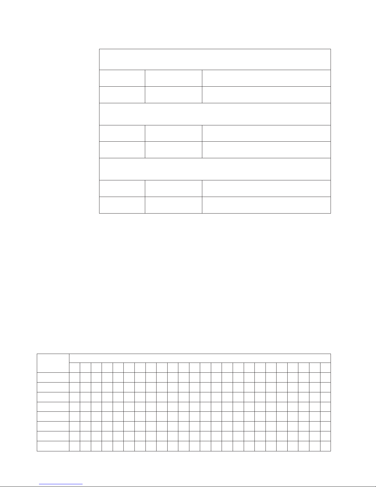
Table 2. DIMM population rules
DIMM Grouping A
All DIMMs in this group must be the same technology (DRAM size, such as 2 Gbit)
DIMM 1, DIMM8DIMM 2, DIMM 7 All DIMMs must be the same DRAM width (such
as 4R x 8)
DIMM 3, DIMM6DIMM 4, DIMM 5 All DIMMs must be the same DRAM width (such
as 4R x 8)
DIMM Grouping B
All DIMMs in this group must be the same technology (DRAM size, such as 2 Gbit)
DIMM 13,
DIMM 17
DIMM 15,
DIMM 19
All DIMMs in this group must be the same technology (DRAM size, such as 2 Gbit)
DIMM 9, DIMM21DIMM 10, DIMM 22 All DIMMs must be the same DRAM width (such
DIMM 11,
DIMM 23
DIMM 14, DIMM18 All DIMMs must be the same DRAM width (such
as 4R x 8)
DIMM 16, DIMM 20 All DIMMs must be the same DRAM width (such
as 4R x 8)
DIMM Grouping C
as 4R x 8)
DIMM 12, DIMM 24 All DIMMs must be the same DRAM width (such
as 4R x 8)
Notes:
v Each DIMM pair must be the exact same size and speed. For example, DIMM 1
and DIMM 8 must be the same size and speed. DIMM 2 and DIMM 7 must be
the same size and speed. However, DIMM 1 and DIMM 2 have to be the same
technology, but they do not need to be the same size and speed.
v When populating the IBM MAX5, use the DIMMs with the greatest size first. For
example, install all 8 GB DIMMs before you install 4 GB DIMMs. Populate the
DIMMs according to the DIMM population table for your environment. See
Table 3 through Table 5 on page 35 for the DIMM population order.
The installation order for DIMMs depends on whether you intend to optimize the
DIMM installation for performance or for power saving.
The following table lists the memory configurations and installation order to
optimize the IBM MAX5 for performance.
Table 3. System memory configuration for performance
Installed
memory
2 DIMMs X X
4 DIMMs X X X X
6 DIMMs X X X X X X
8 DIMMs X X X X X X X X
10 DIMMs X X X X X XXXX X
12 DIMMs X X XXXXXXXX XX
14 DIMMs X X X X X X X X XXXX XX
16 DIMMs X X X X X X X XXXX XXX X X
123456789101112131415161718192021222324
DIMM connector
34 IBM BladeCenter HX5 Type 7873, 7872, 1910, and 1909: Installation and User's Guide
Page 45

Table 3. System memory configuration for performance (continued)
Installed
memory
18 DIMMs X X X X X X XXXXXX XXX XXX
20 DIMMs XXXXXXXX XXXXXX XXX XXX
22 DIMMs XXXXXXXX XXXXXXXXXXX XXX
24 DIMMs XXXXXXXXXXXXXXXXXXXXXXXX
123456789101112131415161718192021222324
DIMM connector
The following table lists the memory configurations and installation order to
optimize the IBM MAX5 for power saving.
Table 4. System memory configuration for power saving (uses a maximum of 8 DIMMs)
Installed
memory
2 DIMMs X X
4 DIMMs X X X X
6 DIMMs X X X X X X
8 DIMMs XXXXXXXX
Table 5. System memory configuration for mirroring with power savings (uses a maximum of 16 DIMMs). This
configuration mirrors the DIMMs in DIMM Grouping A with the DIMMs in DIMM Grouping B.
Note: Mirroring is supported between DIMM pairs.
Installed
memory
4 DIMMs X X X X
8 DIMMs X X X X XXXX
12 DIMMs X X X X X X X X X X X X
16 DIMMs XXXXXXXX XXXXXXXX
123456789101112131415161718192021222324
123456789101112131415161718192021222324
DIMM connector
DIMM connector
DIMM installation procedure
To install a DIMM, complete the following steps:
1. Before you begin, read “Safety” on page v and “Installation guidelines” on
page 23.
2. Read the documentation that comes with the DIMMs.
3. Locate the DIMM connectors (see “Blade server connectors - BladeCenter HX5”
on page 21). Determine the DIMM connector into which you will be installing
memory.
4. If another memory module is already installed in the DIMM connector, remove
it (see “Removing a DIMM - BladeCenter HX5” on page 42).
5. Touch the static-protective package that contains the DIMM to any unpainted
metal surface on the BladeCenter unit or any unpainted metal surface on any
other grounded rack component in the rack in which you are installing the
DIMM for at least 2 seconds; then, remove the DIMM from its package.
6. To install the DIMMs, repeat the following steps for each DIMM that you
install.
Chapter 3. Installing optional devices 35
Page 46

a. Make sure that both retaining clips on the DIMM connector into which you
are installing the DIMM are in the open position (standing straight up).
b. Turn the DIMM so that the DIMM keys align correctly with the DIMM
connector on the system board.
Attention: To avoid breaking the retaining clips or damaging the DIMM
connector, handle the clips gently.
c. Press the DIMM into the DIMM connector. The retaining clips lock the
DIMM into the connector.
d. Make sure that the small tabs on the retaining clips are in the notches on
the DIMM. If there is a gap between the DIMM and the retaining clips, the
DIMM has not been correctly installed. Press the DIMM firmly into the
connector, and then press the retaining clips toward the DIMM until the
tabs are fully seated. When the DIMM is correctly installed, the retaining
clips are parallel to the sides of the DIMM.
Removing a DIMM - IBM MAX5
Use this information to remove a dual inline memory module (DIMM) from the
IBM MAX5 expansion blade.
The following illustration shows how to remove a DIMM from the expansion
blade.
To remove a DIMM, complete the following steps:
1. Before you begin, read “Safety” on page v and “Installation guidelines” on
page 23.
2. Carefully lay the expansion blade on a flat, static-protective surface.
3. Open the expansion blade cover (see “Removing the blade server cover” on
page 25 for instructions).
36 IBM BladeCenter HX5 Type 7873, 7872, 1910, and 1909: Installation and User's Guide
Page 47

4. Locate the DIMM connectors (see “Blade server connectors - IBM MAX5” on
page 21). Determine which DIMM you want to remove from the expansion
blade.
Attention: To avoid breaking the retaining clips or damaging the DIMM
connectors, handle the clips gently.
5. Make sure that both retaining clips on DIMM connector into which you will be
removing the DIMM are in the open position.
6. Using your fingers, pull the DIMM out of the connector.
Installing an SSD expansion card
Use this information to install an SSD expansion card.
To install an SSD expansion card, complete the following steps:
1. Before you begin, read “Safety” on page v and “Installation guidelines” on
page 23.
2. If a CFFh expansion card is installed, remove it (see “Removing a CFFh
expansion card” on page 49 for instructions).
3. Insert the back of the SSD expansion card into the expansion-card standoffs on
the blade server and rotate the expansion card down toward the system board.
Note: The expansion card standoff in the middle of the blade server has two
slots. The top slot is for the CFFh expansion card. Be sure to insert the SSD
expansion card into the bottom slot of the expansion-card standoff that is
located in the middle of the blade server.
4. Carefully push down on the SSD expansion card (pressing on the blue label)
until the expansion card is seated.
Note: Make sure that the expansion card lever is in the closed position.
Expansion
card
standoff
Expansion
card
Expansion
card
standoff
Removing an SSD expansion card
Use this information to remove an SSD expansion card.
To remove an SSD expansion card, complete the following steps:
Chapter 3. Installing optional devices 37
Page 48

1. Before you begin, read “Safety” on page v and “Installation guidelines” on
page 23.
2. Locate the blue expansion card lever on the SSD expansion card and lift the
lever to release the SSD expansion card from the blade expansion connector on
the system board.
3. Rotate the SSD expansion card up and lift it away from the expansion-card
standoffs.
Expansion
card
standoff
Expansion
Expansion
card
standoff
card
Release
handle
Installing a solid state drive
Use this information to install a solid state drive.
You can install up to two solid state drives in the SSD expansion card. The blade
server supports using RAID 0 or RAID 1 when two storage drives are installed.
See “Using the LSI Logic Configuration Utility program” on page 82 for
information about RAID configuration.
To install a solid state drive, complete the following steps:
1. Remove the SSD expansion card (see “Removing an SSD expansion card” on
page 37 for instructions).
2. Turn over the SSD expansion card.
Drive 0
Drive 1
SSD
3. Touch the static-protective package that contains the solid state drive to any
unpainted metal surface on the BladeCenter unit or any unpainted metal surface
on any other grounded rack component; then, remove the solid state drive from
the package.
4. Slide the solid state drive into the slot until it is firmly seated in the connector.
38 IBM BladeCenter HX5 Type 7873, 7872, 1910, and 1909: Installation and User's Guide
Page 49

5. If you have a second solid state drive to install, repeat steps 3 and 4.
6. Close the retention lever and secure it with the blue tab.
Note: You might have to press the blue tab before you close the retention lever.
7. Install the SSD expansion card (see “Installing an SSD expansion card” on page
37 for instructions).
Removing a solid state drive
Use this information to remove a solid state drive.
The blade server has a solid state drive expansion card for installing or removing
solid state drives. To remove a solid state drive, complete the following steps:
1. Before you begin, read “Safety” on page v and “Installation guidelines” on
page 23.
2. Remove the SSD expansion card (see “Removing an SSD expansion card” on
page 37 for instructions).
3. Turn over the SSD expansion card.
Drive 0
Drive 1
SSD
4. Press down on the blue tab. The retention lever automatically opens so that the
solid state drive or drives are accessible.
5. Slide the solid state drive out of the slot.
Note: When you remove a drive from the SSD expansion card, consider
labeling the drive to indicate the slot from which the drive was removed so
that you can install the drive back into the same slot.
6. Close the retention lever and secure it with the blue tab.
Note: You might need to press the blue tab before you close the retention lever.
Installing a DIMM - BladeCenter HX5
The blade server has a total of 16 direct inline memory module (DIMM) slots. The
blade server supports very low profile (VLP) DDR3 DIMMs with error code
correction (ECC) in 2 GB, 4 GB, 8 GB, and 16 GB capacities.
For a current list of supported DIMMs for the blade server, see
http://www.ibm.com/servers/eserver/serverproven/compat/us/eserver.html.
Depending on the memory mode that is set in the Setup utility, the blade server
can support a minimum of 4 GB and a maximum of 128 GB of system memory on
the system board in a blade server with one processor. If two microprocessors are
installed, the blade server can support a minimum of 8 GB and a maximum of 256
GB of system memory.
Chapter 3. Installing optional devices 39
Page 50

Memory must be installed in pairs of DIMMs per processor installed. DIMMs must
be the same size, speed, and technology within installed pairs.
If a single processor is installed, it can access the first eight DIMM slots. The
following table lists the memory configurations and installation order for the
BladeCenter HX5 when one processor is installed.
Table 6. System memory configuration for a single processor (1 microprocessor)
Installed
memory
2 DIMMs X X
4 DIMMs X X X X
6 DIMMs XXXXX X
8 DIMMs XXXXXXXX
12345678
DIMM socket
The following table lists the memory configurations and installation order for the
BladeCenter HX5 when two processors are installed.
Table 7. System memory configuration for a two processors (2 microprocessors)
Installed memory
2 DIMMs X X
4 DIMMs X X X X
6 DIMMs X X X X X X
8 DIMMs X X X X X X X X
10 DIMMs XXXXX XX XX X
12 DIMMs XXXXX XXXXXX X
14 DIMMs XXXXXXXXXXXXX X
16 DIMMs XXXXXXXXXXXXXXXX
12345678910111213141516
DIMM socket
Important: If you are installing memory in a scalable blade complex, you should
install the DIMMs to have a balance of memory among processors. Additional
memory can be installed in the top-most BladeCenter HX5 of the scalable blade
complex blade server so that you do not need to disassemble the scalable blade
complex. For example, if you are installing four DIMMs in a scalable blade
complex consisting of two BladeCenter HX5 blade servers, you would install two
DIMMs (in sockets 1 and 4) of each blade server.
If one processor is installed, memory mirroring is set up as follows:
Table 8. Memory mirroring with one processor
DIMM Quadrant Mirrored Quadrant
DIMM 1, DIMM 2, DIMM 3, DIMM 4 DIMM 5, DIMM 6, DIMM 7, DIMM 8
If two processors are installed, memory mirroring is set up as follows:
40 IBM BladeCenter HX5 Type 7873, 7872, 1910, and 1909: Installation and User's Guide
Page 51

Table 9. Memory mirroring with two processors
DIMM Quadrant Mirrored Quadrant
DIMM 1, DIMM 2, DIMM 3, DIMM 4 DIMM 5, DIMM 6, DIMM 7, DIMM 8
DIMM 9, DIMM 10, DIMM 11, DIMM 12 DIMM 13, DIMM 14, DIMM 15, DIMM 16
The BladeCenter HX5 blade server also supports memory sparing, in which the
contents of the failing DIMM are transferred to the spare DIMM. To enable
memory sparing, the DIMMs installed for each processor must be identical.
Note: See “Installing a DIMM - IBM MAX5” on page 33 for more information
about memory requirements for the IBM MAX5 expansion blade.
If one processor is installed, memory sparing is set up as follows:
Table 10. Memory sparing with one processor
DIMM Pair Spare Pair
DIMM 1, DIMM 4 DIMM 2, DIMM 3
DIMM 5, DIMM 8 DIMM 6, DIMM 7
If two processors are installed, memory sparing is set up as follows:
To install a DIMM, complete the following steps:
Table 11. Memory sparing with two processors
DIMM Pair Spare Pair
DIMM 1, DIMM 4 DIMM 2, DIMM 3
DIMM 5, DIMM 8 DIMM 6, DIMM 7
DIMM 9, DIMM 12 DIMM 10, DIMM 11
DIMM 13, DIMM 16 DIMM 14, DIMM 15
To install a DIMM, complete the following steps:
1. Before you begin, read “Safety” on page v and “Installation guidelines” on
page 23.
2. Locate the DIMM connectors (see “Blade server connectors - BladeCenter HX5”
on page 21). Determine the DIMM connector into which you will be installing
memory.
3. If another memory module is already installed in the DIMM connector, remove
it (see “Removing a DIMM - BladeCenter HX5” on page 42).
4. Touch the static-protective package that contains the DIMM to any unpainted
metal surface on the BladeCenter unit or any unpainted metal surface on any
other grounded rack component in the rack in which you are installing the
DIMM for at least two seconds; then, remove the DIMM from its package.
5. To install the DIMMs, repeat the following steps for each DIMM that you
install:
Chapter 3. Installing optional devices 41
Page 52

a. Make sure that both retaining clips on the DIMM connector into which you
are installing the DIMM, are in the open position.
b. Turn the DIMM so that the DIMM keys align correctly with the DIMM
connector on the system board.
Attention: To avoid breaking the retaining clips or damaging the DIMM
connectors, handle the clips gently.
c. Press the DIMM into the DIMM connector. The retaining clips will lock the
DIMM into the connector.
d. Make sure that the small tabs on the retaining clips are in the notches on
the DIMM. If there is a gap between the DIMM and the retaining clips, the
DIMM has not been correctly installed. Press the DIMM firmly into the
connector, and then press the retaining clips toward the DIMM until the
tabs are fully seated. When the DIMM is correctly installed, the retaining
clips are parallel to the sides of the DIMM.
Removing a DIMM - BladeCenter HX5
Use this information to remove a dual inline memory module (DIMM) from the
blade server.
The following illustration shows how to remove a DIMM from the blade server.
To remove a DIMM, complete the following steps:
1. Before you begin, read “Safety” on page v and “Installation guidelines” on
page 23.
2. Locate the DIMM connectors (see “Blade server connectors - BladeCenter HX5”
on page 21). Determine which DIMM you want to remove from the blade
server.
42 IBM BladeCenter HX5 Type 7873, 7872, 1910, and 1909: Installation and User's Guide
Page 53

Attention: To avoid breaking the retaining clips or damaging the DIMM
connectors, handle the clips gently.
3. Make sure that both retaining clips on DIMM connector into which you will be
removing the DIMM are in the open position.
4. Using your fingers, pull the DIMM out of the connector.
Installing a hypervisor key
Use these instructions to install a hypervisor key in the blade server.
If you are using the BladeCenter HX5 blade server in a virtualized environment,
you might need to install a hypervisor key, depending on the virtualization
software that you are using. If you are using a scalable blade complex that is
configured as a single hardware partition, install the hypervisor key in the bottom
(left) blade server in the complex.
If the blade servers in a scalable blade complex are operating independently, you
might have to install a hypervisor key in each blade server. To determine whether
you need a hypervisor key, see the documentation that comes with your
virtualization software. For more information about virtualization, see
http://www.ibm.com/itsolutions/virtualization/.
Note: The BladeCenter HX5 supports the option part number 41Y8278, which
contains VMWare ESXi 4.0. When you order a replacement, order 42D0545, which
is a blade 2 GB USB key.
The following illustration shows the installation of the hypervisor key.
Interposer
card
Key
To install a hypervisor key, complete the following steps:
1. Before you begin, read “Safety” on page v and “Installation guidelines” on
page 23.
2. Remove the access panel if you have the standard heat sinks installed.
Note: If you have the tall heat sinks installed, you do not need to remove the
access panel.
Chapter 3. Installing optional devices 43
Page 54

a. Using a screwdriver or a coin, turn each of the screws toward the middle of
the blade server until they are in the unlocked position.
b. While you lift the back of the access panel, slide the panel away from the
bezel.
3. Remove the hypervisor interposer:
a. Locate the hypervisor interposer on the system board (see “Major
components of the blade server” on page 12).
b. Press down on the front edge of the hypervisor interposer to disengage the
hypervisor interposer from the hypervisor interposer card guide.
c. Carefully lift the hypervisor interposer up from the system board.
4. Touch the static-protective package that contains the hypervisor key to any
unpainted metal surface on the BladeCenter unit or any unpainted metal surface
on any other grounded rack component in the rack in which you are installing
the hypervisor key for at least 2 seconds; then, remove the USB module from
its package.
5. Install the hypervisor key into the hypervisor adapter:
a. Orient the connector on the hypervisor key with the connector on the
hypervisor adapter.
b. Use your fingers to push the hypervisor key into the hypervisor adapter.
6. Install the hypervisor adapter:
a. Orient the connector on the hypervisor interposer with the interposer
connector on the system board, aligning the pins on the side of the
hypervisor interposer with the pinholes on the interposer connector (see
“Blade server connectors - BladeCenter HX5” on page 21).
b. Use your fingers to push the adapter into the connector on the blade server.
Attention: Be careful not to damage the pins on the hypervisor interposer.
7. Install the access panel if you have standard heat sinks installed.
Note: If you have the tall heat sinks installed, you do not need to install the
access panel.
44 IBM BladeCenter HX5 Type 7873, 7872, 1910, and 1909: Installation and User's Guide
Page 55

a. Make sure that the screws on the access panel are in the open position (the
screw insert is parallel to the side of the access panel).
b. Slide the back of the cover under the blade server bezel, aligning the screws
with the slots on the blade server.
c. Using a screwdriver or a coin, turn each of the screws away from the
middle of the blade server until it is in the locked position.
Removing a hypervisor key
Use this information to remove a hypervisor key from the blade server.
The following illustration shows the removal of a hypervisor key from the blade
server.
Interposer
card
Key
To remove the hypervisor key, complete the following steps:
1. Before you begin, read “Safety” on page v and “Installation guidelines” on
page 23.
2. Remove the access panel if you have the standard heat sinks installed.
Chapter 3. Installing optional devices 45
Page 56

Note: If you have the tall heat sinks installed, you do not need to remove the
access panel.
a. Using a screwdriver or a coin, turn each of the screws toward the middle of
the blade server until they are in the unlocked position.
b. While you lift the back of the access panel, slide the panel away from the
bezel.
3. Locate the hypervisor interposer on the system board (see “Major components
of the blade server” on page 12).
4. Press down on the front edge of the hypervisor interposer to disengage the
hypervisor interposer from the hypervisor interposer card guide.
5. Carefully lift the hypervisor interposer up from the system board.
6. Pull the hypervisor key away from the hypervisor interposer.
Installing an I/O expansion card
The following sections describe how to install the following expansion cards:
v CFFh expansion cards, for example:
– QLogic 2-Port 10Gb Converged Network Adapter
– QLogic Ethernet and 8 GB Fibre Channel Expansion Card
– 2/4-Port Gb Ethernet Expansion Card
– 2-Port 40 Gb Infiniband Expansion Card
– Brocade 2-Port 10 Gb Ethernet Converged Network Adapter
– Broadcom 4-Port 10 Gb Ethernet Expansion Card
– Broadcom 2-Port 10 Gb Ethernet Expansion Card (CFFh)
– Emulex Virtual Fabric Adapter
– Emulex Virtual Fabric Adapter Advanced
– Intel 10Gb 2-Port Ethernet Expansion Card
v CIOv expansion cards, for example:
– Ethernet Expansion Card
– QLogic 8 Gb Fibre Channel Expansion Card
– QLogic 4 Gb Fibre Channel Expansion Card
46 IBM BladeCenter HX5 Type 7873, 7872, 1910, and 1909: Installation and User's Guide
Page 57

– SAS Connectivity Card
Note: A CIOv expansion card is supported for all combinations.
The following illustration shows the cards that are supported in a blade server.
SSD
expansion
ALTERNATELY
TIGHTEN
SCREWS
card
CIOv
expansion
card
CFFh
expansion
card
For information about installing an SSD expansion card, see “Installing an SSD
expansion card” on page 37.
To determine which expansion cards are supported in the BladeCenter HX5 blade
server, see http://www.ibm.com/servers/eserver/serverproven/compat/us/
eserver.html.
Product documentation for expansion cards is available at http://
publib.boulder.ibm.com/infocenter/bladectr/documentation/index.jsp?topic=/
com.ibm.bladecenter.common.nav.doc/bc_expansion_cards_welcome_page.html.
Installing a CIOv expansion card
Use these instructions to install a CIOv expansion card in the blade server.
The following illustration shows the location and installation of a CIOv expansion
card.
Expansion
card
To install a CIOv expansion card, complete the following steps:
1. Before you begin, read “Safety” on page v and “Installation guidelines” on
page 23.
Chapter 3. Installing optional devices 47
Page 58

2. If a CFFh expansion card is installed, remove it (see “Removing a CFFh
expansion card” on page 49 for instructions).
3. Locate the CIOv expansion connector (see “Blade server connectors BladeCenter HX5” on page 21).
4. Touch the static-protective package that contains the expansion card to any
unpainted metal surface on the BladeCenter unit or any unpainted metal surface
on any other grounded rack component; then, remove the expansion card from
the package.
5. Orient the connector on the expansion card with the CIOv expansion connector
on the system board; then, press the card into the CIOv expansion connector.
6. Firmly press on the indicated locations to seat the expansion card.
Note: For device-driver and configuration information to complete the
installation of the expansion card, see the documentation that comes with the
expansion card.
7. Install the CFFh expansion card, if you removed one from the blade server (see
“Installing a CFFh expansion card” for instructions).
Installing a CFFh expansion card
Use these instructions to install a compact-form-factor expansion card in the blade
server.
The blade server supports a horizontal-combination-form-factor (CFFh) expansion
card. The following illustration shows how to install a CFFh expansion card.
Expansion
card
Expansion
card
standoff
To install a CFFh expansion card, complete the following steps:
1. Before you begin, read “Safety” on page v and “Installation guidelines” on
page 23.
2. Locate the blade server expansion connector (see “Blade server connectors BladeCenter HX5” on page 21).
3. If a cover is installed on the blade expansion connector, remove it by using
your fingers to lift the cover from the blade expansion connector.
4. Touch the static-protective package that contains the expansion card to any
unpainted metal surface on the BladeCenter unit or any unpainted metal surface
on any other grounded rack component; then, remove the expansion card from
the package.
48 IBM BladeCenter HX5 Type 7873, 7872, 1910, and 1909: Installation and User's Guide
Page 59

5. Orient the expansion card and slide the slots at the back of the card onto the
pins on the expansion-card standoff; then, gently pivot the card into the blade
server expansion connector.
6. Firmly press on the indicated locations to seat the expansion card.
Note: For device-driver and configuration information to complete the
installation of the expansion card, see the documentation that comes with the
expansion card.
Removing an I/O expansion card
The following sections describe how to remove the following expansion cards:
v CFFh
v CIOv
For information about removing an SSD expansion card, see “Removing an SSD
expansion card” on page 37.
Removing a CFFh expansion card
Use these instructions to remove a CFFh expansion card from the blade server.
To remove a CFFh expansion card, complete the following steps:
1. Before you begin, read “Safety” on page v and “Installation guidelines” on
page 23.
2. Locate the CFFh expansion card. The CFFh card is installed in the blade
expansion connector (see “Blade server connectors - BladeCenter HX5” on page
21).
3. Use your fingers to hold the edge of the CFFh expansion card where it
connects to the blade expansion connector; then, lift up on the card.
Expansion
card
Expansion
card
standoff
4. Lift the card away from the expansion-card standoff.
Removing a CIOv expansion card
Use these instructions to remove a CIOv expansion card from the blade server.
The following illustration shows how to remove a vertical-combination-I/O (CIOv)
expansion card.
Release
lever
Chapter 3. Installing optional devices 49
Page 60

Expansion
card
To remove a CIOv expansion card, complete the following steps:
1. Before you begin, read “Safety” on page v and “Installation guidelines” on
page 23.
2. Remove the CFFh expansion card, if one is installed (see “Removing a CFFh
expansion card” on page 49 for instructions).
3. Locate the CIOv expansion connector (see “Blade server connectors BladeCenter HX5” on page 21).
4. Using your fingers, move the retaining clips away from the CIOv card; then, lift
the card out of the connector.
Installing a microprocessor and heat sink
Use this information to install a microprocessor and heat sink in the blade server.
Note: The optional microprocessors that IBM supports are limited by the capacity
and capability of the server. Any microprocessors that you install must have the
same specifications as the microprocessors that came with the blade server.
The following illustration shows how to install a microprocessor and heat sink in
the blade server.
Heat sink
Microprocessor
heat sink filler
50 IBM BladeCenter HX5 Type 7873, 7872, 1910, and 1909: Installation and User's Guide
Page 61
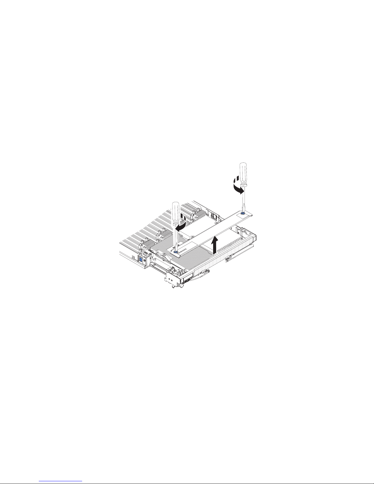
Attention:
1. Do not use any tools or sharp objects to lift the locking lever on the
microprocessor socket. Doing so might result in permanent damage to the
system board.
2. Do not touch the contacts in the microprocessor socket. Touching these contacts
might result in permanent damage to the system board.
To install a microprocessor and heat sink, complete the following steps:
1. Before you begin, read “Safety” on page v and “Installation guidelines” on
page 23.
2. Carefully lay the blade server on a flat, static-protective surface.
3. Remove the access panel if you are installing standard heat sinks.
Note: If you installing tall heat sinks, you do not need to remove the access
panel.
a. Using a screwdriver or a coin, turn each of the screws toward the middle
of the blade server until they are in the unlocked position.
b. While you lift the back of the access panel, slide the panel away from the
bezel.
4. Remove the access panel if you have the standard heat sinks installed.
Note: If you have the tall heat sinks installed, you do not need to remove the
access panel.
Chapter 3. Installing optional devices 51
Page 62

a. Using a screwdriver or a coin, turn each of the screws toward the middle
of the blade server until they are in the unlocked position.
b. While you lift the back of the access panel, slide the panel away from the
bezel.
5. Open the microprocessor socket release lever and retainer.
Microprocessor
release lever
Microprocessor
retainer
a. Rotate the release lever on the microprocessor socket from its closed and
locked position until it stops in the fully open position (approximately a
135° angle).
b. Rotate the microprocessor retainer on the microprocessor socket from its
closed position until it stops in the fully open position (approximately a
135° angle).
6. If a dust cover is installed over the microprocessor socket, lift the dust cover
from the socket and store it in a safe place.
7. Install the microprocessor in the microprocessor installation tool.
52 IBM BladeCenter HX5 Type 7873, 7872, 1910, and 1909: Installation and User's Guide
Page 63

Attention: If you are installing E7 series microprocessors in the blade server,
you must use the microprocessor installation tool with the text “X7500 + E7”
on the bottom of the tool (see the following illustration). Tools that do not
have this text on the bottom will not work correctly with the E7 series
microprocessors.
X7500
+
E7
a. Remove the static-protective bag and the foam surrounding the bag from
the box.
b. Touch the static-protective bag that contains the new microprocessor to
any unpainted surface on the BladeCenter chassis or any unpainted metal
surface on any other grounded rack component.
c. Carefully remove the microprocessor from the static-protective bag,
touching only the edges of the microprocessor.
d. If there is a plastic protective cover on the bottom of the microprocessor,
carefully remove it.
Protective
cover
e. Put the microprocessor back in the box, component side down, on the
f. Twist the handle of the installation tool counterclockwise so that it is in the
g. Using the triangle on the microprocessor to align it with the installation
h. Twist the handle of the installation tool clockwise to secure the
Microprocessor
solid piece of foam.
open position.
tool, place the microprocessor on the underside of the tool.
microprocessor in the tool.
Note: You can pick up or release the microprocessor by twisting the
microprocessor installation tool handle.
Chapter 3. Installing optional devices 53
Page 64

Handle
Installation
tool
Microprocessor
8. Carefully place the microprocessor into the microprocessor socket, using the
alignment tabs on the microprocessor with the alignment notches in the
microprocessor socket as a guide.
The alignment holes on the tool will not sit flush on the microprocessor
bracket screws. However, the holes can be used as a guide to ensure the
proper alignment between the microprocessor installation tool and the
microprocessor bracket.
Attention:
v Do not press the microprocessor into the socket.
v Do not touch exposed pins of the microprocessor socket.
v Make sure that the microprocessor is oriented and aligned correctly in the
socket before you try to close the microprocessor retainer.
v Do not touch the thermal material on the bottom of the heat sink or on top
of the microprocessor. Touching the thermal material will contaminate it. If
the thermal material on the microprocessor or heat sink becomes
contaminated, contact your service technician.
Installation
tool
Alignment
holes
Screws
9. Carefully close the microprocessor retainer.
10. Rotate the locking lever on the microprocessor socket to the closed and locked
position. Make sure that the lever is secured in the locked position by pressing
the tab on the microprocessor socket.
54 IBM BladeCenter HX5 Type 7873, 7872, 1910, and 1909: Installation and User's Guide
Microprocessor
Page 65

11. If you are reinstalling a heat sink that was removed from the blade server,
complete the following steps:
Attention:
v Do not touch the thermal material on the bottom of the heat sink. Touching
the thermal material will contaminate it. If the thermal material on the
microprocessor or heat sink becomes contaminated, contact your service
technician.
v Do not touch exposed pins of the microprocessor socket.
a. Make sure that the thermal material is still on the bottom of the heat sink
and on the top of the microprocessor.
b. Align and place the heat sink on top of the microprocessor in the retention
bracket, thermal material side down. Press firmly on the heat sink.
c. Align the three screws on the heat sink with the holes on the heat-sink
retention module.
d. Press firmly on the captive screws and tighten them with a screwdriver,
alternating among the screws until they are tight. If possible, each screw
should be rotated two full rotations at a time. Repeat until the screws are
tight. Do not overtighten the screws by using excessive force. If you are
using a torque wrench, tighten the screws to 8.5 Newton-meters (Nm) to
13 Nm (6.3 foot-pounds to 9.6 foot-pounds).
12. If you are installing a new heat sink, complete the following steps:
Attention:
v Do not set down the heat sink after you remove the plastic cover.
v Do not touch the thermal material on the bottom of the heat sink. Touching
the thermal material will contaminate it. If the thermal material on the
microprocessor or heat sink becomes contaminated, contact your service
technician.
v Do not touch exposed pins of the microprocessor socket.
a. Remove the plastic protective cover from the bottom of the heat sink.
b. Align and place the heat sink on top of the microprocessor in the retention
bracket, thermal material side down. Press firmly on the heat sink.
c. Align the screws on the heat sink with the holes on the heat-sink retention
module.
d. Press firmly on the captive screws and tighten them with a screwdriver,
alternating among the screws until they are tight. If possible, each screw
should be rotated two full rotations at a time. Repeat until the screws are
tight. Do not overtighten the screws by using excessive force. If you are
using a torque wrench, tighten the screws to 1.13 ± 0.13 Newton-meters
(Nm) (10 ± 0.15 in-lbs).
13. Make sure that, at a minimum, memory modules are installed in DIMM
connectors 1 and 4. See “Installing a DIMM - BladeCenter HX5” on page 39
for more information on installing a memory module.
14. Install the access panel if you removed it earlier.
Chapter 3. Installing optional devices 55
Page 66

a. Make sure that the screws on the access panel are in the open position (the
screw insert is parallel to the side of the access panel).
b. Slide the back of the cover under the blade server bezel, aligning the
screws with the slots on the blade server.
c. Using a screwdriver or a coin, turn each of the screws away from the
middle of the blade server until it is in the locked position.
Installing the 1-node speed burst card
Use this information to install a 1-node speed burst card in a blade server.
To install a 1-node speed burst card, complete the following steps:
Alignment
pins
56 IBM BladeCenter HX5 Type 7873, 7872, 1910, and 1909: Installation and User's Guide
Page 67

1. Before you begin, read “Safety” on page v and “Installation guidelines” on
page 23.
2. Stand the blade server upright on a clean, flat work surface, with the scalability
filler connector facing up.
3. Open the lower handle (rotate the lower handles down) to allow the blade
server to sit flat on the work surface.
4. Remove the scalability filler from the blade server or 2-node scalability card
(see “Installing the 2-node scalability card” on page 60). To remove the
scalability filler, complete the following steps:
a. Using the 3/16" hex driver that is provided with the 1-node speed burst
card, loosen the nut that attaches the filler to the blade server.
b. Lift the filler off the blade server.
5. Align the pins on the bottom of the 1-node speed burst card with the holes on
the scalability connector on the blade server.
6. Press down firmly so that the 1-node speed burst card is flush with the
scalability connector on the blade server.
7. Tighten the screw on the filler by hand to ensure that the screw threads start
properly.
Important: Always hand tighten the screw before using the 3/16" hex driver.
8. Using the 3/16" hex driver, tighten the nut that attaches the 1-node speed burst
card to the blade server.
Note: If you are using a torque driver, the correct torque is 15 in-lb.
Removing the 1-node speed burst card
Use this information to remove the 1-node speed burst card from a blade server.
To remove the 1-node speed burst card, complete the following steps.
Alignment
pins
Chapter 3. Installing optional devices 57
Page 68

1. Before you begin, read “Safety” on page v and “Installation guidelines” on
page 23.
2. Stand the blade server upright on a clean, flat work surface, with the scalability
connector facing up.
3. Open the lower handle (rotate the lower handles down) to allow the blade
server to sit flat on the work surface.
4. Using the 3/16" hex driver that comes with the 1-node speed burst card, loosen
the nut that attaches the 1-node speed burst card to the blade server.
5. Lift the 1-node speed burst card off the blade server.
Completing the installation
To complete the installation, complete the following tasks.
1. Assemble the scalable blade complex if necessary (see “Assembling a scalable
blade complex”).
2. Install the IBM MAX5 expansion blade if necessary (see “Installing an IBM
MAX5” on page 62).
3. Close the blade server cover (see “Installing the blade server cover” on page
67).
Statement 21
CAUTION:
Hazardous energy is present when the blade server is connected to the power
source. Always replace the blade server cover before installing the blade
server.
4. Reinstall the blade server into the BladeCenter chassis (see “Installing a blade
server in a BladeCenter chassis” on page 68).
5. Turn on the blade server (see “Turning on the blade server” on page 15). If you
have just connected the power cords of the BladeCenter chassis to electrical
outlets, you must wait until the power LED on the blade server flashes slowly
before you press the power button.
6. For certain optional devices, you might have to run the blade server Setup
utility to configure the blade server (see Chapter 4, “Configuring the blade
server,” on page 71). See the documentation that comes with your optional
device for additional information.
Assembling a scalable blade complex
Use this information to assemble a scalable blade complex.
To assemble a scalable blade complex, you will need the following parts:
v Two BladeCenter HX5 blade servers
v 2-node scalability kit, which includes the 2-node scalability card, the scalability
tray, and the 3/16" hex driver.
To assemble a scalable blade complex, complete the following steps.
Note: Make sure that you installed a hypervisor key in the primary blade server, if
required, to use the scalable blade complex as a single hardware partition in a
virtualized environment. To determine whether you need to install a hypervisor
58 IBM BladeCenter HX5 Type 7873, 7872, 1910, and 1909: Installation and User's Guide
Page 69

key, see the documentation that comes with your virtualization software. For more
information about virtualization, see http://www.ibm.com/itsolutions/
virtualization/.
1. Before you begin, read “Safety” on page v and “Installation guidelines” on
page 23.
2. Install the scalability tray in the topmost blade server (see “Installing the
scalability tray” for instructions).
3. Attach the blade server with the scalability tray to the bottom blade server.
Cover
Pins
Blade server
cover release
Blade server
cover release
a. Lower the topmost blade server so that the slots at the rear slide down onto
the pins at the rear of the bottom blade server, as shown in the illustration.
b. Pivot the topmost blade server to the closed position, as shown in the
illustration, until it clicks into place.
4. Install the 2-node scalability card (see “Installing the 2-node scalability card” on
page 60).
Installing the scalability tray
Use this information to install the scalability tray on a blade server.
To install the scalability tray, complete the following steps:
1. Before you begin, read “Safety” on page v and “Installation guidelines” on
page 23.
2. Carefully lay the blade server on a flat, static-protective surface, with the cover
side down.
3. Align the scalability tray flush with the blade server in the start position. The
pins on the scalability tray should be aligned with the holes in the blade server.
Chapter 3. Installing optional devices 59
Page 70

4. Pressing down firmly on the middle of the tray, slide the scalability tray
forward toward the bezel until there is an audible click each side of the blade
server.
5. Attempt to pull the scalability tray back to ensure that the scalability tray is
firmly seated.
6. Look in the holes on each side of the blade server to ensure that the spring
plates are engaged.
Installing the 2-node scalability card
Use this information to install the 2-node scalability card on a blade server.
To install the 2-node scalability card, complete the following steps:
1. Before you begin, read “Safety” on page v and “Installation guidelines” on
page 23.
2. Stand the blade servers upright on a clean, flat work surface, with the
scalability connector on the blade servers facing up.
60 IBM BladeCenter HX5 Type 7873, 7872, 1910, and 1909: Installation and User's Guide
Page 71

3. Release the lower handles (rotate the lower handles down) to allow the blade
servers to sit flat on the work surface.
4. Align the pins on the bottom of the IBM 2-node scalability card with the holes
on the scalability connector on the blade server.
5. Press down firmly so that the 2-node scalability card is flush with the
scalability connector on the blade server.
Alignment
pins
Alignment
pins
Chapter 3. Installing optional devices 61
Page 72

6. Make sure that the 2-node scalability card is flush with the edge of the blade
server.
7. Alternately tighten the screws on the 2-node scalability card by hand to ensure
that the screw threads start properly.
Important: Always hand tighten each screw before you use the 3/16" hex
driver.
8. Alternately tighten each screw on the 2-node scalability card using the 3/16"
hex driver. Alternate the tightening of each screw until both screws are
tightened.
Note: If you are using a torque driver, the correct torque is 15 in-lb.
Installing an IBM MAX5
Use these instructions to install an IBM MAX5.
Note: Before installing the IBM MAX5 expansion blade, make sure that you have
updated the firmware on the BladeCenter HX5 blade server to the latest level. If
you attach and try to use the IBM MAX5 expansion blade without updating the
server firmware, you might get unexpected system behavior or the server might
not power on. For information about updating the firmware on the BladeCenter
HX5 blade server, see “Updating firmware and device drivers” on page 82.
There are two versions of the IBM MAX5 expansion blade, referred to as the IBM
MAX5 version 1 and IBM MAX5 version 2 in this document. IBM MAX5 version 2
has a "MAX5" identifying label on the bottom of the front bezel. The functionality
of the two IBM MAX5 expansion blades are equivalent except for the type of
DIMMs supported. The type of DIMMs supported will differ, depending on the
version of IBM MAX5 expansion blade installed. For the list of DIMMs available
for your IBM MAX5 expansion blade, see the Problem Determination and Service
Guide or go to http://www.ibm.com/systems/support/ for an updated parts
listing.
To install an IBM MAX5 expansion blade, complete the following steps.
62 IBM BladeCenter HX5 Type 7873, 7872, 1910, and 1909: Installation and User's Guide
Page 73

IBM MAX5
Blade server
cover release
Upper
ridge
Powe r
jumper
Blade server
cover release
1. Before you begin, read “Safety” on page v and “Installation guidelines” on
page 23.
2. Remove the cover on the BladeCenter HX5 blade server if one is installed (see
“Removing the blade server cover” on page 25 for instructions).
3. Locate the power sharing connector on the BladeCenter HX5 blade server and
remove the power sharing cover if one is installed (see “Blade server
connectors - BladeCenter HX5” on page 21).
4. There are two types of access panels available on the BladeCenter HX5 blade
server, depending on whether tall heat sinks are installed in the blade server.
Complete the following steps if you are installing an IBM MAX5 expansion
blade on a BladeCenter HX5 blade server that has tall heat sinks:
a. Remove the operator control panel access panel:
Chapter 3. Installing optional devices 63
Page 74

1) Using a screwdriver, remove each of the screws on the right access
panel.
2) Lift the access panel away from the blade server.
b. Remove the embedded hypervisor card access panel:
1) Using a screwdriver, remove each of the screws on the right access
panel.
2) Lift the access panel away from the blade server.
c. Install the EMC gasket on the upper ridge of the BladeCenter HX5 blade
server bezel.
d. Install the operator control panel access panel:
1) Align the holes in the access panel with the holes in the blade server.
2) Use a screwdriver to install the screws in the holes of the access panel.
e. Install the embedded hypervisor key access panel:
64 IBM BladeCenter HX5 Type 7873, 7872, 1910, and 1909: Installation and User's Guide
Page 75

1) Align the holes in the access panel with the holes in the blade server.
2) Use a screwdriver to install the screws in the holes of the access panel.
f. Remove the heat sink access plates on the IBM MAX5 expansion blade.
1) Lay the IBM MAX5 expansion blade on a flat, static-protective surface,
cover side down.
2) Use a screwdriver to remove both heat sink access plates.
5. Touch the static-protective package that contains the IBM MAX5 to any
unpainted metal surface on the BladeCenter unit or any unpainted metal surface
on any other grounded rack component; then, remove the optional expansion
unit from the package.
6. Orient the IBM MAX5 as shown in the illustration.
7. Lower the IBM MAX5 so that the slots at the rear slide down onto the cover
pins at the rear of the blade server; then, pivot the IBM MAX5 down onto the
blade server.
8. Press the IBM MAX5 firmly into the closed position until it clicks into place.
9. Install the IBM MAX5 1-node scalability card (see “Installing the IBM MAX5
1-node Scalability card” on page 66 for instructions).
Chapter 3. Installing optional devices 65
Page 76

Installing the IBM MAX5 1-node Scalability card
Use this information to install the IBM MAX5 1-node scalability card on a blade
server.
To install the IBM MAX5 1-node scalability card, complete the following steps.
1. Before you begin, read “Safety” on page v and “Installation guidelines” on
page 23.
2. Remove the 1-node Speed Burst card (see “Installing the 1-node speed burst
card” on page 56) or scalability filler from the blade server, depending on
which you have installed. To remove the scalability filler, complete the
following steps:
a. Using the socket nut driver provided with the scalability kit, loosen the
nut that attaches the filler to the blade server.
b. Lift the filler off of the blade server.
3. Install the IBM MAX5 expansion blade (see “Installing an IBM MAX5” on
page 62).
4. Remove the cover for the expansion blade (see “Removing the blade server
cover” on page 25 for instructions).
5. Stand the blade server and expansion blade upright on a clean, flat work
surface, with the scalability connector on the blade servers facing up.
6. Open the lower handles (rotate the lower handles down) to allow the blade
server and expansion blade to sit flat on the work surface.
7. Align the pins on the bottom of the IBM MAX5 1-node scalability card with
the holes on the scalability connector on the blade server.
8. Press down firmly so that the 1-node scalability card is flush with the
scalability connector on the blade server.
66 IBM BladeCenter HX5 Type 7873, 7872, 1910, and 1909: Installation and User's Guide
Page 77

9. Make sure that the 1-node scalability card is flush with the edge of the blade
server.
10. Alternately tighten the screws on the 1-node scalability card by hand to
ensure that the screw threads start properly.
Important: Always hand tighten each screw before you use the 3/16" hex
driver.
Installing the blade server cover
Use these instructions to install and close the cover for a blade server or for the
topmost blade server in a scalable blade complex.
Attention: You cannot insert the blade server into the BladeCenter chassis until
the cover is installed and closed. Do not attempt to override this protection.
Statement 21
CAUTION:
Hazardous energy is present when the blade server is connected to the power
source. Always replace the blade cover before installing the blade server.
To install and close the blade server cover, complete the following steps:
Chapter 3. Installing optional devices 67
Page 78

1. Before you begin, read “Safety” on page v and “Installation guidelines” on
page 23.
2. Carefully lay the blade server on a flat, static-protective surface, orienting the
blade server with the bezel pointing toward you.
3. Lower the cover so that the slots at the rear slide down onto the pins at the
rear of the blade server, as shown in the illustration. Before you close the cover,
make sure that all components are installed and seated correctly and that you
have not left loose tools or parts inside the blade server.
Blade server
cover
Cover
pins
Blade server
cover release
4. Pivot the cover to the closed position, as shown in the illustration, until it clicks
into place.
Installing a blade server in a BladeCenter chassis
Use these instructions to install a BladeCenter HX5 blade server in a BladeCenter
chassis.
The following illustration shows how to install a BladeCenter HX5 blade server
into a BladeCenter chassis. See the documentation for your BladeCenter chassis for
additional information.
68 IBM BladeCenter HX5 Type 7873, 7872, 1910, and 1909: Installation and User's Guide
Page 79

Statement 21
CAUTION:
Hazardous energy is present when the blade server is connected to the power
source. Always replace the blade cover before installing the blade server.
To install a BladeCenter HX5 blade server, complete the following steps.
1. Before you begin, read “Safety” on page v and “Installation guidelines” on
page 23.
2. Select the blade server bay for the blade server; at least one blade server bay is
required.
Notes:
a. For BladeCenter chassis that support up to 14 blade servers, when any
blade server or device is in blade server bay 7 through 14, power modules
must be installed in all four power-module bays. For additional
information, see the Installation and User's Guide for your chassis.
b. If you are reinstalling a blade server that you removed, you must install it
in the same blade server bay from which you removed it. Some blade
server configuration information and update options are established
according to blade server bay number. Reinstalling a blade server into a
different blade server bay from the one it was removed from can have
unintended consequences. If you reinstall the blade server into a different
bay, you might need to reconfigure the blade server.
c. To maintain proper system cooling, do not operate the BladeCenter chassis
without a blade server, expansion unit, or filler module installed in each
blade server bay.
3. Make sure that the release handles on the blade server are in the open position
(perpendicular to the blade server).
4. Slide the blade server into the blade server bay until it stops.
5. Push the release handles on the front of the blade server to the closed position.
Note: After the blade server is installed, the IMM in the blade server initializes
and synchronizes with the advanced management module. This process takes
approximately 90 seconds to complete. The power LED flashes rapidly, and the
power-control button on the blade server does not respond until this process is
complete.
6. Turn on the blade server (see “Turning on the blade server” on page 15 for
instructions).
7. Make sure that the power LED on the blade server control panel is lit
continuously, indicating that the blade server is receiving power and is turned
on.
8. If you have other blade servers to install, do so now.
9. Optional: Write identifying information about one of the labels that come with
the blade servers and place the label on the BladeCenter chassis bezel. See the
documentation for your BladeCenter chassis for information about the label
placement.
Chapter 3. Installing optional devices 69
Page 80

Important: Do not place the label on the blade server or in any way block the
ventilation holes on the blade server.
If this is the initial installation of the blade server in the BladeCenter chassis, you
must configure the blade server through the Setup utility and install the blade
server operating system. See “Updating the blade server configuration” and
Chapter 5, “Installing the operating system,” on page 103 for details.
If you have changed the configuration of the blade server or if you are installing a
different blade server from the one that you removed, you must configure the
blade server through the Setup utility, and you might have to install the blade
server operating system. For more information, see the “Using the Setup utility” on
page 72.
Updating the blade server configuration
Use this information to update the blade server configuration.
When the blade server starts for the first time after you add or remove an internal
device, you might receive a message that the configuration has changed. The Setup
utility automatically starts so that you can save the new configuration settings. See
“Using the Setup utility” on page 72 for more information about the Setup utility.
Some devices have device drivers that you must install. See the documentation
that comes with each device for information about installing device drivers.
The blade server operates as a symmetric multiprocessing (SMP) server, regardless
of how many microprocessors are installed. For optimum performance, you must
upgrade the operating system to support SMP. See Chapter 5, “Installing the
operating system,” on page 103 and your operating-system documentation for
additional information.
70 IBM BladeCenter HX5 Type 7873, 7872, 1910, and 1909: Installation and User's Guide
Page 81

Chapter 4. Configuring the blade server
There are several components on the blade server that you can configure and
several methods for configuring those components.
Note: If you intend to use a scalable blade complex in single partition mode, you
must partition the complex before you turn on the blade servers or begin the
configuration process. See “Partitioning a scalable blade complex” on page 72 for
information.
Typically, you complete the following steps to configure the blade server:
1. Configure the Unified Extensible Firmware Interface (UEFI) firmware for the
blade server. You can configure the UEFI firmware by using the Setup utility or
the Advanced Settings Utility (ASU). For more information about the Setup
utility, see “Using the Setup utility” on page 72. For more information about
ASU, see “Using the Advanced Settings Utility (ASU)” on page 77.
Note: For more information about firmware configuration options, see
Introducing UEFI-Compliant Firmware on IBM System x and BladeCenter Servers at
http://www.ibm.com/systems/support/supportsite.wss/
docdisplay?lndocid=MIGR-5083207&brandind=5000008.
2. Set the boot protocol. To set the boot protocol, use either the Setup Utility or
the Preboot Execution Environment (PXE) boot agent utility program. For more
information about the PXE boot agent utility program, see “Using the PXE boot
agent utility program” on page 76.
Note: You can temporarily redefine the boot order by using the Boot menu
program that is provided with the blade server firmware
3. Configure the RAID array.
You can install up to two solid state drives in the blade server and implement
RAID level-0 (striping) or RAID level-1 (mirror) arrays in operating systems
that are listed on the ServerProven list at http://www.ibm.com/servers/
eserver/serverproven/compat/us/eserver.html. For the blade server, you must
configure the RAID by using the LSI Configuration Utility program.
Note: If you are implementing a scalable blade complex in single partition
mode, you cannot combine the SSD in both the primary and the secondary
server to define a RAID array. RAID arrays can be defined using only the SSDs
within a blade server.
If an optional RAID expansion card is installed, you can use it to control all the
storage drives that are installed in the blade server. See the documentation that
comes with the expansion card for information about how to configure the
RAID array.
Important: You must create the RAID array before you install the operating
system on the blade server.
4. Configure the integrated management module (IMM). To configure the IMM,
use either the Setup utility or the Advanced Settings Utility (ASU).
5. Update the blade server firmware. For more information about updating blade
server firmware, see “Updating firmware and device drivers” on page 82 If you
are performing inband updates to firmware on blade servers operating as a
single partition in a scalable blade complex, see “Updating firmware for blade
© Copyright IBM Corp. 2011 71
Page 82

servers operating as a single partition” on page 83. If you are updating
firmware for blade servers that are operating as independent partitions in a
scalable blade complex or you are performing out-of-band updates to firmware
for blade servers in a scalable blade complex, see “Updating firmware for each
blade server independently” on page 84.
After you configure the blade server, you can install the operating system and
update device drivers (see Chapter 5, “Installing the operating system,” on page
103 for more information).
Partitioning a scalable blade complex
Before you configure the blade servers that are part of a scalable blade complex
operating in single partition mode, you must partition the scalable blade complex.
For more information about scalable blade complexes and operating modes, see
“Working with a scalable blade complex” on page 13.
To partition a scalable blade complex, complete the following steps:
1. From the advanced management module Web interface, click Scalable Complex
> Configuration.
2. Select one or more of the blade servers that are part of the complex.
3. Click Available actions > Create partition.
Using the Setup utility
Use these instructions to start the Setup utility.
To start the Setup utility, complete the following steps:
1. Turn on the blade server (see “Turning on the blade server” on page 15).
2. Immediately give the blade server control of the BladeCenter unit shared
keyboard, video, and mouse ports.
v If you are managing the blade server by using the BladeCenter system
console, press the KVM select button on the blade server (see “Blade server
controls and LEDs” on page 16 for information).
v If you are managing the blade server from a remote location, see the IBM
BladeCenter Advanced Management Module: User's Guide, IBM BladeCenter
Advanced Management Module: Command-Line Interface Reference Guide,orSerial
over LAN Setup Guide for IBM BladeCenter for information and instructions.
3. When the prompt Press <F1> Setup is displayed, press F1. If you have set an
administrator password, you must type the administrator password to access
the full Setup utility menu. If you do not type the administrator password, a
limited Setup utility menu is available.
4. Follow the instructions on the screen.
The following menu items are on the Setup utility main menu. Depending on the
version of the Unified Extensible Firmware Interface (UEFI), some menu items
might differ slightly from these descriptions.
v System Information
Select this choice to view information about the server. When you make changes
through other choices in the Setup utility, some of those changes are reflected in
the system information; you cannot change settings directly in the system
information. This choice is on the full Setup utility menu only.
72 IBM BladeCenter HX5 Type 7873, 7872, 1910, and 1909: Installation and User's Guide
Page 83

– System Summary
Select this choice to view configuration information, including the ID, speed,
and cache size of the microprocessors, machine type and model of the server,
the serial number, the system UUID, and the details about the memory that is
installed in the BladeCenter HX5 blade server and the IBM MAX5 expansion
blade.
– Product Data
Select this choice to view the system board identifier, the revision level or
issue date of the firmware, the integrated management module and
diagnostics code, and the version and date.
This choice is on the full UEFI Setup Utility menu only.
v System Settings
Select this choice to view or change the server component settings.
– Adapters and UEFI Drivers
Select this choice to view information about the adapters and UEFI drivers
installed in the server.
Note: Before you configure a UEFI-compatible device, you should update the
firmware for your blade server. See “Updating firmware and device drivers”
on page 82 for information about how to update the firmware for your blade
server.
To configure a UEFI-compatible expansion card, complete the following steps:
1. Select Please refresh this page first and press Enter.
2. Select the device driver that you want to configure and press Enter.
3. When you have finished changing settings, press Esc to exit from the
program; select Save to save the settings that you have changed.
– Processors
Select this choice to view or change the processor settings.
– Memory
Select this choice to view or change the memory settings related to the
BladeCenter HX5 blade server and the MAX5 expansion blade.
Note: Select the Memory Scaling Affinity setting to specify whether the
memory in the MAX5 expansion blade is distributed to each processor
domain (non-pooled) or set up as a separate memory domain (pooled).
– Devices and I/O Ports
Select this choice to view or change assignments for devices and
input/output (I/O) ports. You can configure the remote console redirection,
and enable or disable integrated Ethernet controllers. If you disable a device,
it cannot be configured, and the operating system cannot detect it (disabling a
device is equivalent to disconnecting the device).
You can also choose to enable or disable adapter option ROM support.
Disabling support can potentially improve the time it takes the blade server
to start.
– Power
Select this choice to view or change Active Energy Manager (AEM) power
capping to control power consumption and processor performance states.
– Operating Modes
Select this choice to determine operational settings, such as operating mode
(acoustic, efficiency, or performance) and memory speed.
Chapter 4. Configuring the blade server 73
Page 84

– Integrated Management Module
Select this choice to view or change the settings for the integrated
management module (IMM).
- POST Watchdog Timer
Select this choice to view or enable the POST watchdog timer.
- POST Watchdog Timer Value
Select this choice to view or set the POST loader watchdog timer value.
- Reboot System on NMI
Select this choice to enable or disable restarting the system whenever a
nonmaskable interrupt (NMI) occurs. Disable is the default.
- Commands on USB Interface Preference
Select this choice to specify whether the Ethernet over USB interface is
enabled or disabled.
Note: This option is primarily for older operating systems that have
problems with USB communications device class (CDC) Ethernet interfaces.
Disabling this option will cause the following issues:
v Online update packages will not work.
v Updates that use Bootable Media Creator (BoMC) will not work because
BoMC uses the LAN over USB interface.
v You must install the IPMI device driver to use ASU to change the IMM
or UEFI configuration.
v You cannot set the IMM OS Loader watchdog.
- Network Configuration
Select this choice to view the system management network interface port,
the IMM MAC address, the current IMM IP address, and host name; define
the static IMM IP address, subnet mask, and gateway address; specify
whether to use the static IP address or have DHCP assign the IMM IP
address; save the network changes; and reset the IMM.
- Reset IMM to Defaults
Select this choice to reset the IMM to the default settings.
- Reset IMM
Select this choice to reset the IMM.
– Legacy Support
Select this choice to view or set legacy support.
- Force Legacy Video on Boot
Select this choice to enable or disable force INT video support, if the
operating system does not support UEFI video output standards. The
default is Enable.
- Rehook INT
Select this choice to enable or disable devices from taking control of the
boot process. The default is Disable.
- Legacy Thunk Support
Select this choice to enable or disable UEFI to interact with PCI mass
storage devices that are non-UEFI compliant. The default is Enable.
– System Security
Select this choice to view or configure security options for Trusted Platform
Module (TPM).
74 IBM BladeCenter HX5 Type 7873, 7872, 1910, and 1909: Installation and User's Guide
Page 85

– Network
Select this choice to view or configure the network device options, such as
iSCSI, PXE, and Broadcom.
– Trusted Platform Module (TPM)
Select this choice to view and configure TPM settings.
v Date and Time
Select this choice to set the date and time for the server. The date is set in
month/day/year format. The time is set in 24-hour format (hour:minute:second).
This choice is on the full UEFI Setup Utility menu only.
v Start Options
Select this choice to view or change the start options, including the startup
sequence, keyboard NumLock state, PXE boot option, and PCI device boot
priority. Changes in the startup options take effect when you start the blade
server.
The startup sequence specifies the order in which the blade server checks
devices to find a boot record. The blade server starts from the first boot record
that it finds. If the blade server has Wake on LAN hardware and software and
the operating system supports Wake on LAN functions, you can specify a
startup sequence for the Wake on LAN functions. For example, you can define a
startup sequence that checks for a disc in the CD-RW/DVD drive, then checks
the hard disk drive, and then checks a network adapter.
This choice is on the full UEFI Setup utility menu only.
v Boot Manager
Select this choice to view, add, delete, or change the device boot priority, boot
from a file, select a one-time boot, or reset the boot order to the default setting.
v System Event Logs
Select this choice to access the System Event Manager, where you can view the
POST event log and the system-event log.
The POST event log contains the three most recent error codes and messages
that were generated during POST.
The system-event log contains POST and system management interrupt (SMI)
events and all events that are generated by the baseboard management
controller that is embedded in the integrated management module.
Important: If the system-error LED on the front of the server is lit but there are
no other error indications, clear the system-event log. Also, after you complete a
repair or correct an error, clear the system-event log to turn off the system-error
LED on the front of the server.
– POST Event Viewer
Select this choice to enter the POST event viewer to view the POST error
messages.
– System Event Log
Select this choice to view the system-event log.
– Clear System Event Log
Select this choice to clear the system-event log.
v User Security
Select this choice to set, change, or clear passwords.
Chapter 4. Configuring the blade server 75
Page 86

You can set, change, and delete a power-on password and an administrator
password through this selection. If you set a power-on password, you must type
the power-on password to complete the system startup and to have access to the
Setup Utility menu.
The password must be from 6 to 20 characters. You can use any combination of
ASCII printable characters for the password. Keep a record of your password in
a secure place.
If you forget the power-on password, you can regain access to the blade server
either by removing the blade server battery and then reinstalling it or by using
the power-on password override switch (see the Problem Determination and
Service Guide for instructions).
An administrator password is intended to be used by a system administrator; it
limits access to the full Setup utility menu.
Attention: If you set an administrator password and then forget it, there is no
way to change, override, or remove it. You must replace the system board.
v Save Settings
Select this choice to save the changes that you have made in the settings.
v Restore Settings
Select this choice to cancel the changes that you have made in the settings and
restore the previous settings.
v Load Default Settings
Select this choice to cancel the changes that you have made in the settings and
restore the factory settings.
v Exit Setup
Select this choice to exit from the Setup utility. If you have not saved the
changes that you have made in the settings, you are asked whether you want to
save the changes or exit without saving them.
Using the PXE boot agent utility program
Use the Preboot Execution Environment (PXE) boot agent utility program to select
the boot protocol and other boot options and to select a power-management
option.
Notes:
1. The blade server does not support Remote Program Load (RPL) selection for
the boot protocol option.
2. Enabling PXE might reduce the number of optional expansion modules that
your blade server can manage.
To start the PXE boot agent utility program, complete the following steps:
1. Turn on the blade server (see “Turning on the blade server” on page 15).
2. When the Broadcom NetXtreme Boot Agent vX.X.X prompt is displayed, press
Ctrl + S. You have 2 seconds (by default) to press Ctrl + S after the prompt is
displayed.
3. Follow the instructions on the screen to change the settings of the selected
items.
76 IBM BladeCenter HX5 Type 7873, 7872, 1910, and 1909: Installation and User's Guide
Page 87

Using the Boot Selection Menu program
The Boot Selection Menu program is a built-in, menu-driven configuration utility
program that you can use to temporarily redefine the first startup device without
changing settings in the Setup utility.
To use the Boot Selection Menu program, complete the following steps:
1. Turn off the blade server.
2. Restart the blade server.
3. Press F12 (Select Boot Device). If a bootable USB mass storage device is
installed, a submenu item (USB Key/Disk) is displayed.
4. Use the Up Arrow and Down Arrow keys to select an item from the Boot
Selection Menu and press Enter.
The next time the blade server starts, it returns to the startup sequence that is set
in the Setup utility.
Using the Advanced Settings Utility (ASU)
You can use the Advanced Settings Utility (ASU) to modify firmware settings from
the command line on multiple operating systems, such as Linux, Windows, and
Windows Professional Edition (PE).
You can use the ASU to perform the following tasks:
v Modify selected firmware UEFI settings without restarting the blade server to
access F1 settings.
v Modify selected settings in integrated management module (IMM) based blade
servers for the IMM firmware and IBM System x Server Firmware.
v Modify a limited number of VPD settings on IMM-based blade servers.
v Modify iSCSI boot settings.
For more information about using the ASU, see http://www.ibm.com/systems/
support/supportsite.wss/docdisplay?lndocid=TOOL-CENTER&brandind=5000016.
Updating the Universal Unique Identifier (UUID)
The Universal Unique Identifier (UUID) must be updated when the system board
is replaced. Use the Advanced Settings Utility to update the UUID.
You can download the ASU from the IBM website. To download the ASU and
update the UUID, complete the following steps.
1. Download the Advanced Settings Utility (ASU) from http://www.ibm.com/
systems/support/supportsite.wss/docdisplay?lndocid=TOOL-ASU
&brandind=5000016.
2. Select one of the following methods to access the IMM to set the UUID:
v Online from the target system (LAN or keyboard console style (KCS) access)
v Remote access to the target system (LAN based)
v Bootable media containing ASU (LAN or KCS, depending upon the bootable
media)
Note: IBM provides a method for building a bootable media. You can create
a bootable media using the Bootable Media Creator (BoMC) application from
http://www.ibm.com/systems/support/supportsite.wss/
Chapter 4. Configuring the blade server 77
Page 88

docdisplay?lndocid=TOOL-BOMC&brandind=5000016. In addition, the
Windows-based and Linux-based toolkits are also available to build a
bootable media.
3. Copy and unpack the ASU package, which also includes other required files, to
the server. Be sure to unpack the ASU and the required files to the same
directory. In addition to the application program (asu or asu64), the following
files are required:
v For Windows-based operating systems:
– ibm_rndis_server_os.inf
– device.cat
v For Linux-based operating systems:
– cdc_interface.sh
4. After you unpack ASU, use the following command syntax to set the UUID:
asu set SYSTEM_PROD_DATA.SysInfoUUID uuid_value [access_method]
uuid_value
Up to 16-byte hexadecimal value assigned by you.
access_method
The access method that you selected to use from the following
methods:
v Online authenticated LAN access, use the following syntax:
[host imm_internal_ip] [user imm_user_id][password imm_password]
Where:
imm_internal_ip
The IMM internal LAN/USB IP address. The default value is
169.254.95.118.
imm_user_id
The IMM account (1 of 12 accounts). The default value is USERID.
imm_password
The IMM account password (1 of 12 accounts). The default value is
PASSW0RD (with a zero, not the letter O).
Note: If you do not specify any of these parameters, ASU uses the default
values. When the default values are used and ASU is unable to access the
IMM by using the online authenticated LAN access method, ASU
automatically uses the unauthenticated KCS access method.
The following commands are examples of using the user ID and password
default values and not using the default values:
Example that does not use the user ID and password default values:
asu set SYSTEM_PROD_DATA.SYsInfoUUID uuid_value user user_id
password password
Example that does use the user ID and password default values:
asu set SYSTEM_PROD_DATA.SysInfoUUID uuid_value
v Online KCS access (unauthenticated and user restricted):
You do not need to specify a value for access_method when you use this
access method.
Example:
asu set SYSTEM_PROD_DATA.SysInfoUUID uuid_value
78 IBM BladeCenter HX5 Type 7873, 7872, 1910, and 1909: Installation and User's Guide
Page 89

The KCS access method uses the IPMI/KCS interface. This method requires
that the IPMI driver be installed. Some operating systems have the IPMI
driver installed by default. ASU provides the corresponding mapping layer.
See the Advanced Settings Utility User's Guide for more details. You can access
the guide from http://www.ibm.com/systems/support/supportsite.wss/
docdisplay?lndocid=TOOL-ASU&brandind=5000016..
v Remote LAN access. Use the following syntax:
Note: When you use the remote LAN access method to access IMM using
the LAN from a client, the host and the imm_external_ip address are required
parameters.
host imm_external_ip [user imm_user_id[[password imm_password]
Where:
imm_external_ip
The external IMM LAN IP address. There is no default value. This
parameter is required.
imm_user_id
The IMM account (1 of 12 accounts). The default value is USERID.
imm_password
The IMM account password (1 of 12 accounts). The default value is
PASSW0RD (with a zero, not a letter O).
The following commands are examples of using the user ID and password
default values and not using the default values:
Example that does not use the user ID and password default values:
asu set SYSTEM_PROD_DATA.SYsInfoUUID uuid_value host imm_ip
user user_id password password
Example that does use the user ID and password default values:
asu set SYSTEM_PROD_DATA.SysInfoUUID uuid_value host imm_ip
v Bootable media:
You can also build a bootable media using the applications available at
http://www.ibm.com/systems/support/supportsite.wss/
docdisplay?lndocid=TOOL-CENTER&brandind=5000016..
5. Restart the blade server.
Updating the DMI/SMBIOS data
The Desktop Management Interface (DMI) must be updated when the system
board is replaced. Use the Advanced Settings Utility to update the DMI.
To download the ASU and update the DMI, complete the following steps.
1. Download the Advanced Settings Utility (ASU) from http://www.ibm.com/
systems/support/supportsite.wss/docdisplay?lndocid=TOOL-ASU
&brandind=5000016.
2. ASU sets the DMI in the IMM. Select one of the following methods to access
the IMM to set the DMI:
v Online from the target system (LAN or keyboard console style (KCS) access)
v Remote access to the target system (LAN based)
v Bootable media containing ASU (LAN or KCS, depending upon the bootable
media)
Chapter 4. Configuring the blade server 79
Page 90

Note: IBM provides a method for building a bootable media. You can create
a bootable media using the Bootable Media Creator (BoMC) application from
http://www.ibm.com/systems/support/supportsite.wss/
docdisplay?lndocid=TOOL-BOMC&brandind=5000016. In addition, the
Windows-based and Linux-based toolkits are also available to build a
bootable media.
3. Copy and unpack the ASU package, which also includes other required files, to
the server. Make sure that you unpack the ASU and the required files to the
same directory. In addition to the application program (asu or asu64), the
following files are required:
v For Windows-based operating systems:
– ibm_rndis_server_os.inf
– device.cat
v For Linux-based operating systems:
– cdc_interface.sh
4. After you unpack ASU. Use the following syntax:
asu set SYSTEM_PROD_DATA.SysInfoProdName m/t_model[access_method]
asu set SYSTEM_PROD_DATA.SysInfoSerialNum s/n [access_method]
asu set SYSTEM_PROD_DATA.SysEncloseAssetTag asset_tag[access_method]
Where:
m/t_model
The server machine type and model number. Type mtm xxxxyyy, where
xxxx is the machine type and yyy is the server model number.
s/n The serial number on the server. Type sn zzzzzzz, where zzzzzzz is the
serial number.
asset_method
The server asset tag number. Type asset
aaaaaaaaaaaaaaaaaaaaaaaaaaaaaaaaa, where
aaaaaaaaaaaaaaaaaaaaaaaaaaaaaaaaa is the asset tag number.
[access_method]
The access method that you select to use from the following methods:
v Online authenticated LAN access. Use the following syntax:
[host imm_internal_ip] [user imm_user_id][password imm_password]
imm_internal_ip
The IMM internal LAN/USB IP address. The default value is
169.254.95.118.
imm_user_id
The IMM account (1 of 12 accounts). The default value is USERID.
imm_password
The IMM account password (1 of 12 accounts). The default value is
PASSW0RD (with a zero, not the letter O).
Note: If you do not specify any of these parameters, ASU uses the default
values. When the default values are used and ASU is unable to access the
IMM using the online authenticated LAN access method, ASU automatically
uses the following unauthenticated KCS access method.
The following commands are examples of using the user ID and password
default values and not using the default values:
Examples that do not use the userid and password default values:
80 IBM BladeCenter HX5 Type 7873, 7872, 1910, and 1909: Installation and User's Guide
Page 91

asu set SYSTEM_PROD_DATA.SYsInfoProdName m/t_model --user
imm_user_id--password imm_password
asu set SYSTEM_PROD_DATA.SYsInfoSerialNum s/n--user imm_user_id
--password imm_password
asu set SYSTEM_PROD_DATA.SYsEncloseAssetTag asset_tag --user
imm_user_id--password imm_password
Examples that do use the user ID and password default values:asu set
SYSTEM_PROD_DATA.SysInfoProdName m/t_model asu set
SYSTEM_PROD_DATA.SysInfoSerialNum s/n asu set
SYSTEM_PROD_DATA.SysEncloseAssetTag asset_tag
v Online KCS access (unauthenticated and user restricted):
You do not need to specify a value for access_method when you use this
access method.
The KCS access method uses the IPMI/KCS interface. This method requires
that the IPMI driver is installed. Some operating systems have the IPMI
driver installed by default. ASU provides the corresponding mapping layer.
See the Advanced Settings Utility Users Guide for more details. You can access
the ASU Users Guide from http://www.ibm.com/systems/support/
supportsite.wss/docdisplay?lndocid=TOOL-ASU&brandind=5000016.
The following commands are examples of using the user ID and password
default values and not using the default values:
Examples that do not use the user ID and password default values:
asu set SYSTEM_PROD_DATA.SYsInfoProdName m/t_model
asu set SYSTEM_PROD_DATA.SYsInfoSerialNum s/n
asu set SYSTEM_PROD_DATA.SYsEncloseAssetTag asset_tag
v Remote LAN access. Use the following syntax:
Note: When using the remote LAN access method to access IMM using the
LAN from a client, the host and the imm_external_ip address are required
parameters.
host imm_external_ip [user imm_user_id][password imm_password]
imm_external_ip
The external IMM LAN IP address. There is no default value. This
parameter is required.
imm_user_id
The IMM account (1 of 12 accounts). The default value is USERID.
imm_password
The IMM account password (1 of 12 accounts). The default value is
PASSW0RD (with a zero, not the letter O).
The following commands are examples of using the user ID and password
default values and not using the default values:
Examples that do not use the user ID and password default values:
asu set SYSTEM_PROD_DATA.SYsInfoProdName m/t_model--host imm_ip --user
imm_user_id --password imm_password
asu set SYSTEM_PROD_DATA.SYsInfoSerialNum s/n --host imm_ip --user
imm_user_id--password imm_password
asu set SYSTEM_PROD_DATA.SYsEncloseAssetTag asset_tag--host imm_ip
--user imm_user_id --password imm_password
Examples that do use the user ID and password default values:
Chapter 4. Configuring the blade server 81
Page 92

asu set SYSTEM_PROD_DATA.SysInfoProdName m/t_model--host imm_ip
asu set SYSTEM_PROD_DATA.SysInfoSerialNum s/n --host imm_ip
asu set SYSTEM_PROD_DATA.SysEncloseAssetTag asset_tag --host imm_ip
v Bootable media:
You can also build a bootable media using the applications available from
http://www.ibm.com/systems/support/supportsite.wss/
docdisplay?lndocid=TOOL-BOMC&brandind=5000016.
5. Restart the blade server.
Using the LSI Logic Configuration Utility program
Use these instructions to start the LSI Logic Configuration Utility program.
You can use the LSI Logic Configuration Utility program to perform the following
tasks:
v Set the device boot order
v Add or remove devices from the boot list
v Manage the RAID configuration
To start the LSI Logic Configuration Utility program, complete the following steps:
Note: The LSI controller on your blade server is a UEFI compatible device. It can
be configured through the Setup utility for your blade server (see “Using the Setup
utility” on page 72).
1. Turn on the blade server, and make sure that the blade server is the owner of
the keyboard, video, and mouse.
2. When the <<<Press Ctrl-C to start LSI Logic Configuration Utility>>>
prompt is displayed, press Ctrl+C.
3. Use the arrow keys to select the controller from the list of adapters; then, press
Enter.
4. Follow the instructions on the screen to change the settings of the selected
items; then, press Enter. If you select SAS Topology or Advanced Adapter
Properties, additional screens are displayed.
Updating firmware and device drivers
IBM periodically makes UEFI code, service processor (IMM) firmware, diagnostic
firmware updates, and device driver updates available for the blade server. Several
methods are available to update the firmware for the blade server.
Note: Typically, you update the firmware before you install the operating system
and update device drivers after the operating system is installed.
If you are updating the firmware for the blade servers in a scalable blade complex
operating in single partition mode, you only must update the firmware for the
primary blade server. When you update the firmware for the primary blade server,
the firmware for the secondary blade server is updated as well. Device drivers are
updated through the operating system.
You can update the firmware and device drivers for the blade server by using one
of the following methods.
v Using UpdateXpress System Packs. UpdateXpress System Packs (UXSP) contain
an integration-tested bundle of online, updatable firmware and device drivers
82 IBM BladeCenter HX5 Type 7873, 7872, 1910, and 1909: Installation and User's Guide
Page 93

for your servers. For more information about UpdateXpress System Packs, see
http://www.ibm.com/systems/support/supportsite.wss/
docdisplay?lndocid=SERV-XPRESS&brandind=5000008
v Using the IBM ToolsCenter Bootable Media Creator. You can use IBM
ToolsCenter Bootable Media Creator to create bootable media that is suitable for
applying firmware updates, running preboot diagnostics, and deploying
Windows operating systems on supported systems. Using IBM ToolsCenter
Bootable Media Creator, you can create a single bootable image on supported
media (such as CD, DVD, ISO image, USB flash drive, or set of PXE files) that
bundles multiple IBM BladeCenter tools and updates from UpdateXpress System
Packs, which contain Windows and Linux
®
firmware and device-driver updates.
You can also create an IBM ServerGuide Setup and Installation CD for deploying
Windows operating systems and updates on supported systems. For more
information about the Bootable Media Creator, see http://www.ibm.com/
systems/support/supportsite.wss/docdisplay?lndocid=TOOL-BOMC
&brandind=5000008.
v Downloading the firmware and device drivers from http://www.ibm.com/
support/fixcentral/systemx/groupView?query.productGroup=ibm
%2FBladeCenter . Follow the instructions that come with the firmware and
device drivers to install them.
You must make sure that you update the firmware for each blade server in the
scalable blade complex to the same levels before resetting the scalable blade
complex. Refer to the following table to select the correct procedure to follow
based on your configuration and preferred update method:
Table 12. Procedures to update firmware for blade servers in a scalable blade complex
Scalable blade complex
mode Inband updates Out-of-band updates
Single partition “Updating firmware for blade
servers operating as a single
partition”
Independent partitions “Updating firmware for each
blade server independently” on
page 84
“Updating firmware for each
blade server independently” on
page 84
“Updating firmware for each
blade server independently” on
page 84
For more information about updating firmware and the preferred methods, see the
Firmware Update Best Practices white paper at http://www-947.ibm.com/
systems/support/supportsite.wss/docdisplay?lndocid=MIGR-5082923
&brandind=5000020.
For additional instructions about updating the firmware before attaching a IBM
MAX5 expansion blade, see http://www.ibm.com/support/entry/portal/
docdisplay?lndocid=MIGR-5085756
Updating firmware for blade servers operating as a single
partition
If you are performing inband updates to firmware on blade servers operating as a
single partition in a scalable blade complex, updates made to the firmware on the
primary blade server are also applied to the secondary blade server.
You can obtain the firmware updates from http://www.ibm.com/support/
fixcentral/systemx/groupView?query.productGroup=ibm%2FBladeCenter .
Chapter 4. Configuring the blade server 83
Page 94

Complete the following steps to update the firmware for the blade servers
operating as a single partition in a scalable blade complex:
1. Run the IMM firmware update package on the primary blade server.
2. Run the UEFI firmware update package on the primary blade server.
3. Run the FPGA firmware update package on the primary blade server.
4. Run the DSA preboot firmware update package the primary blade server.
5. Restart the scalable blade complex to activate the firmware.
The firmware updates that were made to the primary blade server are applied to
the secondary blade server.
Updating firmware for each blade server independently
If you are updating firmware for blade servers that are operating as independent
partitions in a scalable blade complex or you are performing out-of-band updates
to firmware for blade servers in a scalable blade complex, updates must be applied
to each system in the scalable complex independently.
You can obtain the firmware updates from http://www.ibm.com/support/
fixcentral/systemx/groupView?query.productGroup=ibm%2FBladeCenter .
Complete the following steps to update the firmware for the blade servers:
Note: The blade servers in the scalable blade complex must be at the same
firmware levels before they are restarted.
1. Update the IMM firmware on the primary blade server. Then update the IMM
firmware on the secondary blade server.
2. Reset the IMM on the primary and secondary systems. Complete the following
steps to reset the IMM through the advanced management module Web
interface:
a. Click Blade Tasks > Power/Restart.
b. Click the checkbox next to the blade servers to be reset.
c. Click Available actions > Restart Blade System Mgmt Processor.
d. Click Perform Action.
3. Update the UEFI firmware on the primary blade server. Then update the UEFI
firmware on the secondary blade server.
4. Update the FPGA firmware on the primary blade server. Then update the
FPGA firmware on the secondary blade server.
5. Update the DSA preboot firmware on the primary blade server. Then update
the DSA Preboot firmware on the secondary blade server.
6. Restart both blade servers to activate the firmware
You can also use an Expect type script to automate advanced management module
command-line interface (CLI) commands for updating the firmware for both blade
servers. Complete the following steps to use an Expect type script:
1. Download the firmware for the BladeCenter HX5 blade server from
http://www.ibm.com/support/fixcentral/systemx/
groupView?query.productGroup=ibm%2FBladeCenter . Place the files on a
TFTP server that is on the same TCP/IP subnet as the advanced management
module for the chassis in which the blade servers are installed.
84 IBM BladeCenter HX5 Type 7873, 7872, 1910, and 1909: Installation and User's Guide
Page 95

Note: Remember to record the directory location on the TFTP server where you
place the files; you will need that location to run the Expect type script.
2. Generate an Expect type script that will log in to the advanced management
module CLI, update the firmware for the blade servers, and restart the blade
servers when complete.
3. From a computer that is on the same TCP/IP subnet as the advanced
management module for the chassis in which the scalable blade complex is
installed, run the Expect type script.
Example of an Expect script
The following script illustrates how an Expect type script might be created to
update the firmware for both blade servers.
Important: IBM does not provide support for Expect scripts. For more information
about using Expect, see the Expect website at http://expect.sourceforge.net/. For
more information about using the advanced management module CLI, see the
BladeCenter Advanced Management Module Command-Line Interface Reference Guide at
http://publib.boulder.ibm.com/infocenter/bladectr/documentation/topic/
com.ibm.bladecenter.advmgtmod.doc/adv_man_mod_printable_doc.html.
#!/usr/bin/expect
################################################################################
# #
# This tool has been built from the following sources: #
# #
# support/FlashMNBladeViaAmm.exp : 1.1 #
# support/include/Log.exp : 1.9 #
# support/include/AMM.exp : 1.29 #
# support/include/MultiNode.exp : 1.1 #
# support/include/FlashBlade.exp : 1.16 #
# #
################################################################################
################################################################################
# #
# Code from source : support/include/Log.exp #
# #
################################################################################
################################################################################
# #
# Globals. #
# #
################################################################################
log_user 0
exp_internal -f /tmp/diag.txt 0
set fm_logfile ""
set g_normal_timeout_value 30
set timeout $g_normal_timeout_value
################################################################################
# #
# Init the logging system. #
# #
################################################################################
proc log_init { display_stdout } {
global fm_logfile
if {$display_stdout == 0} {
log_user 1
}
set fm_logfile "/tmp/expect_logs.txt"
}
################################################################################
Chapter 4. Configuring the blade server 85
Page 96

# #
# Log to a directory. #
# #
################################################################################
proc log_init_directory { directory } {
global fm_logfile
set fm_logfile "$directory/ExpectLogs.txt"
exp_internal -f $directory/ExpectDiag.txt 0
}
################################################################################
# #
# Temp hack. #
# #
################################################################################
proc log_init_custom { logfile } {
global fm_logfile
global g_module_name
global g_test_results_base_dir
#
# Cache the module name.
#
set g_module_name $logfile
#
# Figure out the logfile path.
#
test_results_set_base_dir
#
# Set it.
#
set fm_logfile "$g_test_results_base_dir/Logfile.txt"
}
################################################################################
# #
# Capture a log message with a nice time stamp. #
# #
################################################################################
proc ft_log { message } {
global fm_logfile
set date_val [ timestamp -format "%m/%d: %X: " ]
log_file $fm_logfile
send_log -- "$date_val $message\n"
log_file
send_user -- "$date_val $message\n"
}
################################################################################
# #
# Bail on a critical error. #
# #
################################################################################
proc ft_error { message } {
ft_log "ERROR: $message"
puts "\n\nERROR: $message"
exit
}
################################################################################
# #
# Code from source : support/include/AMM.exp #
# #
################################################################################
################################################################################
# #
86 IBM BladeCenter HX5 Type 7873, 7872, 1910, and 1909: Installation and User's Guide
Page 97

# Globals. #
# #
################################################################################
set amm_id "" ;# Spawn ID for AMM ssh connection.
set save_amm "" ;# Save pointer of original amm value.
set save_target "" ;# Save pointer for current AMM state.
set save_userid "" ;# Save pointer of original userid value.
set save_password "" ;# Save pointer of original password value.
array set g_imm_fw_levels { } ;# Array of IMM firmware levels.
array set g_uefi_fw_levels { } ;# Array of uEFI firmware levels.
################################################################################
# #
# Unexpected EOF handler. #
# #
################################################################################
proc eof_handler{}{
global save_amm save_userid save_password
ft_log "Unexpected EOF talking to AMM."
#
# Clean up any zombies.
#
catch {close -i $amm_id}
wait -nowait
#
# The AMM closed the connection on us -- try to resume.
#
set amm_id ""
set rv [ amm_login $save_amm $save_userid $save_password ]
set rv [ amm_restore_save_target ]
}
################################################################################
# #
# Save off the current target value. #
# #
################################################################################
proc amm_save_target { string } {
global save_target
set save_target $string
}
################################################################################
# #
# Restore the AMM to its saved target value. #
# #
################################################################################
proc amm_restore_save_target{}{
global amm_id save_target
send -i $amm_id "env -T $save_target\r"
expect -i $amm_id -exact "OK" {
return 0
}
ft_error "Unable to restore AMM target after disconnect."
}
################################################################################
# #
# Handy function to collect all flash failure logs for a given blade. #
# #
################################################################################
proc collect_flash_failure_logs { blade } {
global g_target_blade g_test_results_dir
#
Chapter 4. Configuring the blade server 87
Page 98

# Create a storage space for our output.
#
set g_target_blade $blade
set rv [ test_results_set_cwd ]
#
# Have to be on an MM[N] target.
#
set rv [ amm_set_mm_target ]
#
# Grab the VDBG data from the AMM.
#
ft_log "Blade: $blade -- Collecting AMM vdbg log."
set vdbg_output "$g_test_results_dir/AMM_vdbg.txt"
set rv [ collect_vdbg $vdbg_output ]
if {$rv == 0} {
ft_log "Blade: $blade -- Successfully collected AMM vdbg log."
} else {
ft_log "Blade: $blade -- Failure collecting AMM vdbg log."
}
#
# Grab the FFDC data from the IMM.
#
ft_log "Blade: $blade -- Collecting IMM FFDC logs."
set rv [ imm_ffdc_init_capture $blade ]
set rv [ imm_ffdc_collect_capture $blade ]
set fn [ imm_ffdc_get_service_file_name $blade ]
set rv [ collect_file_from_amm service "." $fn $g_test_results_dir/IMM_FFDC.tgz ]
if {$rv == 0} {
ft_log "Blade: $blade -- Successfully collected IMM FFDC data."
} else {
ft_log "Blade: $blade -- Failure collecting IMM FFDC data."
}
#
# Cleanup.
#
set rv [ imm_ffdc_cleanup_amm $fn ]
}
################################################################################
# #
# Reset all of the configured blades in the chassis. #
# #
################################################################################
proc reset_all_blades{}{
global blade_presence_bits
for {set slot 1} {$slot < 15} {incr slot 1} {
if { ! [info exists blade_presence_bits($slot)]} {
continue
}
set present $blade_presence_bits($slot)
if {$present == 1} {
set rv [ reset_blade $slot ]
if {$rv != 0} {
ft_log "Blade: $slot did not reboot."
}
}
}
}
################################################################################
88 IBM BladeCenter HX5 Type 7873, 7872, 1910, and 1909: Installation and User's Guide
Page 99

# #
# Reset a blade via the AMM. Returns 0 on success and 1 on timeout. #
# #
################################################################################
proc reset_blade { blade } {
global amm_id
#
# Reboot the blade.
#
send -i $amm_id "reset -T blade\[$blade\]\r\n"
expect -i $amm_id "OK" {
ft_log "Blade $blade: Rebooted host OS."
return 0
} timeout {
return 1
}
}
################################################################################
# #
# Reset a blade via the AMM. Returns 0 on success and 1 on timeout. #
# #
################################################################################
proc reset_blade_gator { blade } {
global amm_id
#
# Gator zap.
#
set gator_map {123456789abcdef}
set gator_offset [lindex $gator_map $blade_no]
send -i $amm_id "dbg gator x $gater_offset -Tsystem:mm\[1\]\r\n"
expect -i $amm_id "OK" {
ft_log "Blade $blade: Gator zap."
return 0
} timeout {
return 1
}
}
################################################################################
# #
# Reboot the AMM. #
# #
################################################################################
proc reboot_amm{}{
global amm_id
#
# Reboot the AMM.
#
send -i $amm_id "reset\r"
#
# The AMM CLI needs to have the session opened until it goes away.
#
sleep 10
ft_log "AMM: Rebooted."
return 0
}
################################################################################
# #
# Set the MM target to the value. #
# #
################################################################################
Chapter 4. Configuring the blade server 89
Page 100

proc amm_set_mm_target{}{
global amm_id
#
# We should discover what bay the MM is in, hardcoded to 1 right now.
#
set mm 1
send -i $amm_id "env -T system:mm\[$mm\]\r"
expect -i $amm_id -exact "system:mm\[$mm\]"
expect -i $amm_id "OK" {
set rv [ amm_save_target "system:mm\[$mm\]" ]
return 0
}
return 1
}
################################################################################
# #
# Set the CLI target to ’system’. #
# Returns 0 on success and 1 on failure. #
# #
################################################################################
proc amm_set_system_target{}{
global amm_id
send -i $amm_id "env -T system\r"
expect -i $amm_id "OK" {
set rv [ amm_save_target "system" ]
return 0
}
return 1
}
################################################################################
# #
# Set the CLI target to a blade. #
# Returns 0 on success and 1 on failure. #
# #
################################################################################
proc amm_set_blade_target { blade_no } {
global amm_id
send -i $amm_id "env -T system:blade\[$blade_no\]\r"
expect -i $amm_id "OK" {
set rv [ amm_save_target "system:blade\[$blade_no\]" ]
return 0
}
return 1
}
################################################################################
# #
# Collect the current SOL ready status. #
# #
################################################################################
proc blade_collect_sol_ready_status{}{
global amm_id
send -i $amm_id "sol\r"
expect -i $amm_id "OK" {
} timeout {
return 1
}
expect -i $amm_id "SOL Session: Ready" {
return 0
}
90 IBM BladeCenter HX5 Type 7873, 7872, 1910, and 1909: Installation and User's Guide
 Loading...