

Page 1
Page 2

Page 3

Console Switch
Installation and User’s Guide
Page 4

Page 5
Page 6

Notices and Statements Used in This Document
• Note: These notices provide important tips, guidance, or advice.
• Important: These notices provide important information or advice that might help you avoid
inconvenient or problem situations.
• Attention: These notices indicate possible damage to programs, devices or data.
An attention notice is placed just before the instruction or situation in which damage could
occur.
• Caution: These statements indicate situations that can be potentially hazardous to you. A cau-
tion situation is placed just before the description of a potentially hazardous
procedure step or situation.
• Danger: These statements indicate situations that can be potentially lethal or extremely haz-
ardous to you. A danger statement is placed just before the description of a
potentially lethal or extremely hazardous procedure step or situation.
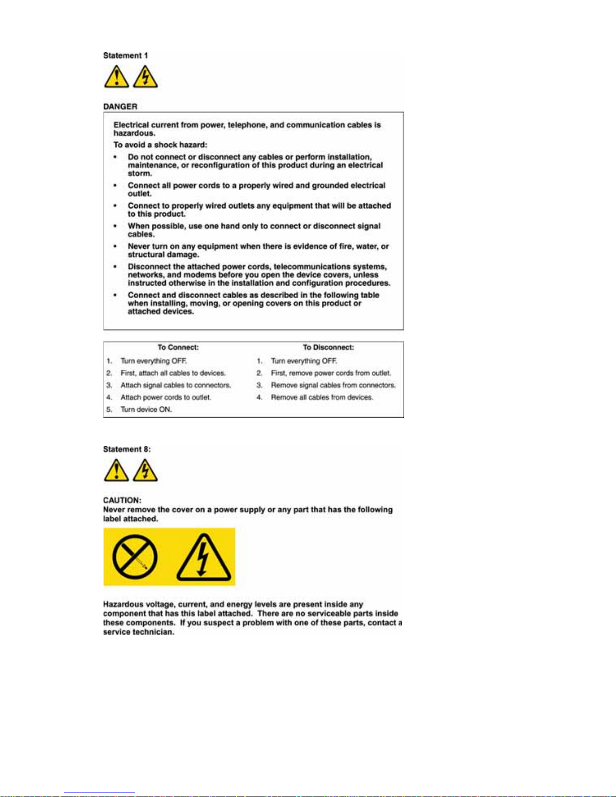
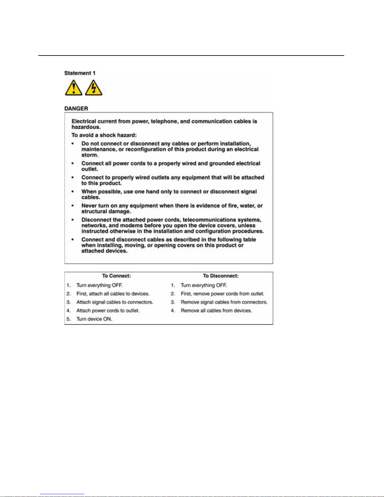
Important:
All caution and danger statements in this documentation beginn with a number. This number is
used to cross reference an English caution or danger statement with translated versions of the
caution or danger statement in the IBM Safety Information book.
For example, if a caution statement begins with a number 1, translations for that caution statement
appear in the IBM Safety Information book under statement 1.
Be sure to read all caution and danger statements in this documentation before perfo rm ing the
instructions. Read any additional safety information that comes with your server or optional device
before you install the device.
Page 7
Page 8

Page 9

ix
le of Contents
List of Figures .................................................................................................................xi
List of Tables................................................................................................................. xiii
Chapter 1: Product Overview.......................................................................................... 1
Features and Benefits ........................................................................................................................1
Switch Cable ......................................................................................................................................1
Safety Precautions .............................................................................................................................4
Rack Mounting of Systems............................................................ .................................. ...................7
Chapter 2: Installation ..................................................................................................... 9
Getting Started.................................................................................................. .................................9
Supplied with the console switch....................................................... .........................................9
Rack Mounting the Console Switch...................................................................................................9
Vertical installation in the side of a rack .......................................... ... ................................. .....9
Horizontal installation in the 1 U rack mounting space ..........................................................10
Installing the Console Switch ..........................................................................................................11
Tiering Multiple Console Switches..................................................................................................13
Adding Earlier-model Switches .......................................................................................................14
Configuring the Console Switch System..........................................................................................16
Chapter 3: Basic Operations......................................................................................... 17
Controlling the System at the Local Ports.......................................................................................17
Viewing and Selecting Ports and Servers........................................................................................17
Selecting servers................................................. ......................................................................19
Navigating the OSCAR Interface.....................................................................................................20
Configuring OSCAR Interface Menus .............................................................................................21
Assigning server names ............................................................................................................22
Assigning device types..............................................................................................................23
Changing the display behavior.................................................................................................25
Controlling the status flag........................................................................................................26
Setting console switch security.................................................... .................................. ...........28
Displaying Version Information ......................................................................................................30
Resetting the Keyboard and Mouse ......................................... .................................. ......................32
TABLE OF CONTENTS
Page 10

x Table of Contents
Scanning the System............................................................................ ................................ .............32
Broadcasting to Servers........................................................ ...........................................................34
Changing the Switch Mode..............................................................................................................36
Setting the Keyboard Country Code............................... .................................. ... ............................37
Appendices..................................................................................................................... 39
Appendix A: Firmware Upgrades....................................................................................................39
Appendix B: Technical Specifications .............................................................................................41
Appendix C: Notices ........................................................................................................................42
Appendix D: Electronic Emission Notices.......................................................................................44
Index................................................................................................................................ 47
Page 11

xi
List of Figures
Figure 1.1: PS/2 Switch Cable and USB Switch Cable....................................................................2
Figure 1.2: Example of a Console Switch Configuration.................................................................4
Figure 2.1: Console Switch vertical installation............................................................................10
Figure 2.2: Console Switch Horizontal Installation.......................................................................11
Figure 2.3: Basic Console Switch Configuration...........................................................................12
Figure 2.4: Console Switch Configuration with a Tiered Switch...................................................13
Figure 2.5: Console Switch Configuration with an Earlier-model Switch.....................................15
Figure 3.1: Example of Configured Main Window ........................................................................18
Figure 3.2: Setup Window..............................................................................................................22
Figure 3.3: Names Window............................................................................................................22
Figure 3.4: Name Modify Window .................................................................................................23
Figure 3.5: Devices Window ..........................................................................................................24
Figure 3.6: Device Modify Window................................................................................................24
Figure 3.7: Menu Window..............................................................................................................25
Figure 3.8: Flag Window................................................................................................................27
Figure 3.9: Set Position Window....................................................................................................27
Figure 3.10: Security Window........................................................................................................28
Figure 3.11: Version Window.........................................................................................................30
Figure 3.12: Cable Selection Window............................................................................................31
Figure 3.13: Cable Version Window..............................................................................................31
Figure 3.14: Scan Window .............................................................................................................33
Figure 3.15: Commands Window...................................................................................................34
Figure 3.16: Broadcast Window.....................................................................................................35
Figure 3.17: Broadcast Enable Window ........................................................................................36
Figure 3.18: Switch Window ..........................................................................................................37
Figure 3.19: Keyboard Window .....................................................................................................37
Figure 3.20: Keyboard Warning Window ......................................................................................38
LIST OF FIGURES
Page 12

xii List of Figures
Page 13

xiii
List of Tables
Table 1.1: Console Switch Cable Resolution and Refresh Rate........................................................2
Table 2.1: Earlier-model Switches ..................................................................................................14
Table 3.1: OSCAR Interface Status Symbols................................................. ..................................18
Table 3.2: OSCAR Interface Navigation Basics..............................................................................20
Table 3.3: Setup Features to Manage Routine Tasks for the Servers..............................................21
Table 3.4: OSCAR Interface Status Flags .......................................................................................26
LIST OF TABLES
Page 14

xiv List of Tables
Page 15

1
CHAPTER
1
Product Overview
Features and Benefits
The IBM 1x8 Console Switch and the IBM 2x16 Console Switch integrate keyboard, video, and
mouse (KVM) switching technology with advanced cable management, flexible access for up to
two simultaneous users, and an intuitive user interface. The console switches feature powerful onscreen management for easy system configuration and server selection.
NOTE: The 1x8 console switch enables a single local user to access any attached servers. The 2x16 console
switch enables two simultaneous users to access attached servers.
The IBM 3M Console Switch Cables (PS/2 and USB) are unique benefits of the console switch. By
using CAT 5 cabling, the switch cable reduces cable clutter, while providing optimal resolution and
video settings. The built-in memory of the switch cable simplifies configuration by assigning and
retaining unique server names and port numbers for each attached server. The switch cable is
powered directly from the server and provides Keep Alive functionality even if the console sw itch
is not turned on. Keep Alive functionality enables the server to operate properly with or without
connectivity to the console switch.
Switch Cable
The switch cable enables direct KVM connectivity to servers attached to the console switch. The
1x8 console switch has 8 Analog Rack Interface (ARI) ports and the 2x16 console switch has 16
ARI ports for connecting switch cables.
Using a PS/2 switch cable you can attach additional switches to expand the console switch system.
This flexibility enables you to add capacity as the data center grows.
Multiplatform Support
The
switch cable
s available with the console switch support PS/2 and USB server environments.
Using the On-Screen Configuration and Activity Reporting (OSCAR
®
) graphical user interface in
conjunction with these cables enables you to switch easily across platforms.
The PS/2 switch cable is used to connect a PS/2 server to a console switch. This cable has one HD15
connector for video, one PS/2 connector for keyboard, an d one PS/2 connector for mouse.
Page 16

2 IBM Console Switch Installation and User’s Guide
The USB switch cable is used to connect a USB server to a console switch. This cable has one HD1 5
connector for video and one USB connector for keyboard and mouse.
Figure 1.1: PS/2 Switch Cable and USB Switch Cable
OSCAR Graphical User Interface
The console switch uses the OSCAR interface, which features intuitive menus to configure the
switch system and select servers. Servers can be identified by a unique name and port number,
enabling you to assign a unique server name.
Security
The OSCAR interface enables you to protect the system with a screen saver password. After a userdefined time, the screen saver mode engages, and access is prohibited until the appropriate
password is entered to reactivate the system.
Video
The console switch provides optimal resolutions for analog VGA, SVGA, and XGA video. You
can achieve resolutions up to 1280 x 1024 with a 3-m (9.8-ft) cable.
Table 1.1: Console Switch Cable Resolution and Refresh Rate
Maximum Resolution Refresh Rate Video Type
720 x 400 70 Hz VGA
640 x 480 60 Hz VGA
640 x 480 72 Hz VESA
640 x 480 75 Hz VESA
USB Switch
Cable
PS/2 Switch
Cable
Page 17

Chapter 1: Product Overview 3
Plug and Play
The console switch also supports Display Data Channel (DDC) Plug and Play, which automates
configuration of the monitor and is compliant with the VESA DDC2B standa rd.
Firmware Upgrades
You can upgrade the firmware at any time through an update utility to be sure that the console
switch system is always running the most current version available. See “Appendix A: Firmware
Upgrades” for more information.
Tiering Expansion
The 1x8 console switch supports up to 8 directly attached servers and the 2x16 console switch
supports up to16 directly attached servers. Each model can conveniently scale to support additional
servers. You can expand the system by tiering with console switches and earlier-model console
switches. This extra tier of units enables you to attach up to 256 servers in one system. See “Tiering
Console Switches” in Chapter 2 for more information.
800 x 600 56 Hz VESA
800 x 600 60 Hz VESA
800 x 600 72 Hz VESA
800 x 600 75 Hz VESA
1024 x 768 60 Hz VESA
1024 x 768 70 Hz VESA
1280 x 1024 75 Hz VGA
Table 1.1: Console Switch Cable Resolution and Refresh Rate
Page 18

4 IBM Console Switch Installation and User’s Guide
Figure 1.2: Example of a Console Switch Configuration
Safety Precautions
Use the following safety guidelines to help ensure your own personal safety and to help protect the
system and working environment from potential damage.
Console Switch
(tiered)
Earlier-model
Switch (tiered)
Switch Cable
(tiered)
Rack of Servers
Critical Server
Local User A
Console Switch
(main)
Local User B
Page 19
Chapter 1: Product Overview 5
Page 20

6 IBM Console Switch Installation and User’s Guide
General
• Observe and follow service markings.
• Do not service any console switch except as explained in the console switch documentation.
• Opening or removing covers that are marked with the triangular symbol with a lightning bolt
might expose you to electrical shock.
• Components inside these compartments should be serviced only by a trained service technician.
• The console switch contains no serviceable components. Do not attempt to open.
• If any of the following conditions occur, unplug the console switch from the electrical outlet
and replace the part or contact the trained service provider:
• The power cable, extension cable, or plug is damaged.
• An object has fallen into the product.
• The console switch has been exposed to water.
• The console switch has been dropped or damaged.
• The console switch does not operate correctly when you follow the operating instructions.
• Keep the console switch away from radiators and heat sources. Also, do not block
cooling vents.
• Do not spill food or liquids on the console switch components, and never operate the console
switch in a wet environment. If the console switch gets wet, see the appropriate section in the
troubleshooting guide or contact the trained service provider.
• Use the console switch only with approved equipment.
• Enable the console switch to cool before removing covers or touching internal components.
• Operate the console switch only from the type of external power source indicated on the elec-
trical ratings label. If you are not sure of the type of power source required, consult the service
provider or local power company.
Page 21

Chapter 1: Product Overview 7
• Be sure that the monitor and attached devices are electrically rated to operate with the power
available in your location.
• Use only power cables provided with the console switch.
• To help prevent electric shock, plug the console switch and peripheral power cables into prop-
erly grounded electrical outlets. These cables are equipped with three-prong plugs to help
ensure proper grounding. Do not use adapter plugs or remove the grounding prong from
a cable.
• Observe extension cable and power strip ratings. Make sure that the total ampere rating of all
products plugged into the power strip does not exceed 80 percent of the ampere ratings limit
for the power strip.
• To help protect the console switch from sudden, transient increases and decreases in electrical
power, use a surge suppressor, line condit ioner, or uninterruptible power supply.
• Position console switch cables and power cables carefully. Route cables so that they cannot be
stepped on or tripped over. Be sure that nothing rests on any cables.
• Do not modify power cables or plugs. Consult a licensed electrician or the power company for
site modifications. Always follow the local and national wiring rules.
Rack Mounting of Systems
• Refer to the rack installation documentation accompanying the rack for specific caution
statements and procedures.
• Elevated ambient temperature: If installed in a closed rack assembly , the operation temperature
of the rack environment can be greater than room ambient. Use care not to exceed the rated
maximum ambient temperature of the unit.
• Reduced air flow: Carefully install the equipment in a rack so that an adequate amount of
airflow is maintained for safe operation of the equipment.
• Mechanical loading: Avoid a potentially hazardous condition caused by uneven mechanical loading
by carefully mounting the equipment in the r ack.
• Circuit overloading: Consideration should be given to the connection of the equipment to the
supply circuit and the effect that overloading of circuits might have on overcurrent protection
and supply wiring. Consider equipment nameplate ratings for maximum current.
• Reliable earthing: Reliable earthing of rack-mounted equipment should be maintained. Pay
particular attention to supply connections other than direct connections to the branch circuit
(for example, use of power strips).
Page 22

8 IBM Console Switch Installation and User’s Guide
Page 23

9
CHAPTER
2
Installation
Getting Started
Before installing the console switch, refer to the following list to ensure you have all of the items
that were shipped with the console switch as well as other items necessary for proper installation.
Supplied with the console switch
• Console switch
• Power cord
• Rack mounting hardware (includes rack mounting brackets)
• Documentation CD
• Quick Installation Guide
• 1U filler panel
Additional items needed
• One IBM 3M Console Switch Cable (PS/2 or USB) per attached server
• One IBM 3M Console Switch Cable (PS/2) per attached switch
• One Phillips screwdriver
Rack Mounting the Console Switch
Before installing the console switch and o t h e r components in the rack (if not already installed),
stabilize the rack in a permanent location. Install the equipment starting at the bottom of the rack,
then work to the top. Avoid uneven loading or overloading of racks.
Vertical installation in the side of a rack
1. Remove the screws on each side of the console switch.
2. Line up the small holes of the L-shaped brackets with the screw holes in the switch.
3. With a Phillips screwdriver , fasten the mounting brackets to the switch using two 8/32” x 1/2”
pan-head screws on each side.
Page 24

10 IBM Console Switch Installation and User’s Guide
4. Mount the switch assembly to the rack by matching the long slots on each bracket to an
appropriate set of holes on the rack. Next, insert a combination hex head screw through the
slots in the bracket and the holes in the rack. Cap the screw with a hex serrated flange nut
and tighten.
NOTE: The mounting holes on the upper and lower side braces in a rack side compartment must be between
50.8 cm (20.0 in.) and 57.3 cm (22.6 in.) apart. If the rack has movable side braces, refer to the rack
documentation for information about relocating side braces if they are not already spaced for this installation.
Figure 2.1: Console Switch vertical installation
Horizontal installation in the 1 U rack mounting space
NOTE: The filler panel must be placed in front of the rack when the console switch is mounted in the horizontal
1 U orientation.
1. Remove the screws on each side of the console switch.
2. Line up the holes in the long side of each mounting bracket.
3. With a Phillips screwdriver , fasten the mounting brackets to the switch using two 8/32” x 1/2”
pan-head screws on each side.
4. Attach four cage nuts or clip nuts to the rack mounting flange of the rack so that the nut is
positioned on the inside of the rack.
5. Mount the switch assembly to the rack by matching the holes in the short side of each
mounting bracket to an appropriate set of matching holes on the rack. Insert the combination
hex-head screws through the slots in the mounting bracket and the holes in the mounting rail,
then into the cage nuts or clip nuts.
Page 25

Chapter 2: Installation 11
Figure 2.2: Console Switch Horizontal Installation
Installing the Console Switch
Connect the supplied power cord into the back of the console switch and then into an appropriate
power source. Figure 2.3 illustrates one possible configuration for the conso le switch. See the following
detailed set of procedures to successfully install the console switch.
Page 26

12 IBM Console Switch Installation and User’s Guide
Figure 2.3: Basic Console Switch Configuration
Connecting a switch cable to a server
1. Locate the switch cable for the console switch.
2. Attach the appropriately col or -coded cable ends t o the keyboard, monitor, and mouse ports on the
first server you will be connecting to the con sole switch.
3. Connect the RJ-45 connector on the PS/2 or USB switch cable to an Analog Rack Interface
(ARI) port on the back of the console switch.
4. Repeat steps 2 to 4 for all servers you want to attach.
Connecting local peripheral devices
1. Select the keyboard, monitor, and mouse to be connected to local user A.
Local User B (2x16 model only)
Configuration Port
(for updating firmware)
Console Switch
Server 1
Servers 2-16
Local User A
Console Switch
Cable
ARI Ports
ACI Port
Page 27

Chapter 2: Installation 13
2. Locate the port set labeled A on the back of the console switch. Connect these peripheral
devices to their respective ports.
3. Repeat these steps for the local port set labeled B (2x16 only).
4. Bundle and label the cables for easy identification.
Tiering Multiple Console Switches
You can tier multiple console switches to enable one or two users to connect to up to 256 servers.
In a tiered system, each ARI port on the main console switch will connect to the Analog Console
Interface (ACI) port on each tiered console switch. Each tiered switch can then be connected to up
to 8 servers on the 1x8 console switch and up to 16 servers on the 2x16 console switch. The
example in Figure 2.4 shows one console switch tiered under the main switch, enabling the
connection of up to 15 primary servers and 16 secondary servers. In this configuration, you could
tier 16 console switches under the main switch, enabling the connection of up to 256 servers. Only
one level of tiering is supported in this type of configuration, which means that you cannot tier
additional earlier-model switches or another console switch. In this configuration, the tiered local
port On-screen Configuration and Activity Reporting (OSCAR) interface is disabled when the
main console switch is tiered below another console switch.
Figure 2.4: Console Switch Configuration with a Tiered Switch
Local User A
Local User B
(2x16 only)
Console Switch
ARI Ports
Primary Servers
ACI Port
Tiered (secondary)
Console Switch
Page 28

14 IBM Console Switch Installation and User’s Guide
NOTE: As shown in Figure 2.4, only the local user A has an ACI port that can be used for the tiered connection.
1. Connect the tiered console switch to each server as described in the previous “Installing the
Console Switch” section.
2. Connect the peripheral devices to local user A of the main switch as described in “Connecting
local peripheral devices.”
3. Attach one end of the CAT 5 cable that will connect the main and tiered console switch to the
RJ-45 (ACI) connector of local user A on the tiered console switch.
4. Attach the other end of the CAT 5 cable to one of the 16 RJ-45 (ARI) ports on the main
console switch.
NOTE: The system will automatically tier the two switches together as one. All servers connected to the tiered
console switch will display on the main console switch server list in the OSCAR interface.
5. Repeat steps 3 and 4 for all additional (secondary) tiered console switches you want
to attach.
Adding Earlier-model Switches
You can add earlier-model switches for easy integration into the existing configuration. In a tiered
system, each ARI port will accommodate up to 16 servers. When earlier-model switches are tiered
under the 1x8 console switch or the 2x16 console switch, the console switch must be at the top
level of the tier. See the following table for earlier-model switches compatible with the console
switch configuration.
Table 2.1: Earlier-model Switches
Earlier-model Switch Option Part Number
NetBAY
™ 1x4 Console Switch
09N4290
NetBAY 2x8 Console Switch 09N4291
Page 29

Chapter 2: Installation 15
Figure 2.5: Console Switch Configuration with an Earlier-model Switch
1. Mount the earlier-model switch into the rack according to the instructions included with
that device.
2. Attach the keyboard, monitor, and mouse connectors of the switch cable to the local port on the
tiered switch.
3. Connect the RJ-45 connector on the PS/2 switch cable to an ARI port on the back of the
console switch.
4. Connect the servers to the tiered switch according to the instructions included with
that device.
5. Power cycle the tiered switch to enable its local port to recognize the switch cable.
6. Repeat steps 2 to 5 for all tiered switches you want to attach to the system.
Connecting local peripheral devices
1. Select the keyboard, monitor, and mouse to be connected to local user A.
Console Switch
PS/2 Switch Cable
Earlier-model Switch
Earlier-model Switch
Server 1
Server 2
Local User
Page 30

16 IBM Console Switch Installation and User’s Guide
2. Locate the port set labeled A on the back of the console switch. Connect these peripherals
devices to their respective ports.
3. For the 2x16 console switch, repeat steps 1 and 2 for the local port set labeled B.
4. Bundle and label the cables for easy identification.
Configuring the Console Switch System
With the console switch system, you can auto detect and configure each port on the cons ole switch.
Chapter 3 provides detailed instructions about naming customization and OSCAR interface setup
and configuration.
Page 31

17
CHAPTER
3
Basic Operations
Controlling the System at the Local Ports
The console switch features two local port sets on the back of the unit that enable you to connect a
monitor and a PS/2 keyboard and mouse for direct local access. The 1x8 console switch enables
you to connect a single local user, whereas the 2x16 console switch enables you to connect two
users. The console switch uses the OSCAR interface, which uses intuitive menus to configure the
system and select servers.
Viewing and Selecting Ports and Servers
Use the OSCAR Main window to view, configure, and control servers directly connected to the
console switch. View the servers by name or port. You will see an OSCAR interface-generated port
list by default when you first launch the OSCAR interface.
The Port column indicates the ARI port to which a server is connected. If you connect an earliermodel switch to the console switch or a tiered console switch, the port numbering displays the ARI
port first, then the switch port to which the server is connected. For example, in Figure 3.1, servers
06-01, 06-03, 06-02, 06-04, and 01-02 are connected to tiered switches.
Accessing the Main window
1. Press Print Screen
to launch the OSCAR interface. The Main window opens.
Page 32

18 IBM Console Switch Installation and User’s Guide
Figure 3.1: Example of Configured Main Window
NOTE: You can also press Ctrl twice within one second to launch the OSCAR interface. You can use this key
sequen c e i n an y p l a c e y o u s e e Prin t Screen th r o u g hout this installation and user’s guide.
Viewing the status of the switch
The status of the servers in the system is indicated in the right columns of the Main window. The
following table describes the status symbols.
Table 3.1: OSCAR Interface Status Symbols
Symbol Description
The switch cable is online (green circle).
The switch cable is offline or is not operating properly.
The server is tiered through a console switch. The server and the console switch are online
and have power.
The server is tiered through a console switch. The server and the console switch are offline
or have no power.
The switch cable is not operating properly (yellow circle).
The switch cable is being accessed by the indicated user channel (green channel letter).
Page 33

Chapter 3: Basic Operations 19
Selecting servers
Use the Main window to select servers. When you select a server, the console switch reconfigures
the keyboard and mouse to the proper settings for that server.
Double-click the server name or port number.
-orIf the display order of the server list is by port (Port
button is selected), type the port number and
press Enter.
-orIf the display order of the server list is by name (Name
button is selected), type the first few
characters of the name of the server to establish it as unique and press Enter.
Selecting the previous server
Press Print Screen
and then Backspace. This key combination toggles you between the previous
and current connections.
Disconnecting the user from a server
Press Print Screen to access OSCAR and then click Disconnect.
-orPress Print Screen and then Alt+0. The status flag on the desktop displays Free. The Free status
indicates that the server is not selected for the user.
NOTE: The status flag displays on the desktop and shows the name or the port number of the selected server or
the status of the selected port.
NOTE: To clear all directly connected offline switch cables from the list, click Clear.
Soft switching
Soft switching is the ability to switch servers using a hot key sequence. You can soft switch to a server by
pressing Print Screen and then typing the first few characters of its name or number. If you have set a
Screen Delay Time and you press the key sequences before that time has elapsed, the OSCAR interface
will not display.
Configuring servers for soft switching
1. Press Print Screen to launch the OSCAR interface. The Main window opens.
2. Click Setup - Menu. The Menu window opens.
3. For Screen Delay Time, type the number of seconds of delay that you want before the Main
window opens after Print Screen is pressed.
The switch cable is blocked by the indicated user channel (black channel letter). For
instance, in Figure 3.1, user B is viewing Forester, but is blocking access to Acton, Barrett,
and Edie, which are connected to the same console switch.
Table 3.1: OSCAR Interface Status Symbols (Continued)
Page 34

20 IBM Console Switch Installation and User’s Guide
4. Click OK.
Soft switching to a server
1. To select a server , press Print Screen. If the display order of the server list is by port (Port button
is selected), type the port number and press Enter.
-or-
If the display order of the server list is by name (Name button is selected), type the first few
characters of the name of the server to establish it as unique and press Enter.
2. To switch back to the previous server, press
Print Screen then Backspace.
Navigating the OSCAR Interface
The following table describes how to navigate the OSCAR interface using the keyboard.
Table 3.2: OSCAR Interface Navigation Basics
Action Result
Print Screen
Press Print Screen twice to send the Print Screen keystroke to the currently selected
device.
F1
Opens the Help screen for the current window.
Esc
Closes the current window without saving changes and returns to the previous one.
In the Main window, it closes the OSCAR interface and returns to the flag.
In a message window, it closes the pop-up window and returns to the
current window.
Alt+Hotkey
Opens windows, selects or checks options, and executes actions when used with
underlined or other designated letters.
Alt+X Closes the current window and returns to the previous one.
Alt+O
Selects the OK button, then returns to the previous window.
Enter
Completes a switch in the Main window and exits the OSCAR interface.
Click on an editable field to select the text for editing and enable the Left and Right
arrow keys to move the cursor. Press Enter to quit the edit mode.
Print Screen
Backspace
Toggles back to the previous selection.
Print Screen
Alt+0
Immediately disconnects the user from a server and no server is selected. The
Status flag displays Free. (This only applies to the 0 on the keyboard and not
the keypad.)
Print Screen
Pause
Immediately turns on screen saver mode (when screen saver is enabled) and
prevents access to that specific console, if it is password protected.
Up/Down Arrows Moves the cursor from line to line in lists.
Page 35

Chapter 3: Basic Operations 21
Configuring OSCAR Interface Menus
You can configure the console switch from the Setup menu within the OSCAR interface. Select the
Names
button when initially setting up the console switch to identify servers by unique names. Select
the other setup features to manage routine tasks for the servers from the OSCAR menu.
Accessing the Setup menu
1. Press Print Screen to launch the OSCAR interface. The Main window opens.
2. Click
Setup. The Setup window opens.
Right/Left Arrows
Moves the cursor between columns. When editing a field, these keys move the
cursor within the column.
Page Up/Page Down Pages up and down through Name and Port lists and Help pages.
Home/End Moves the cursor to the top or bottom of a list.
Delete Deletes characters in a field.
Table 3.2: OSCAR Interface Navigation Basics (Continued)
Table 3.3: Setup Features to Manage Routine Tasks for the Servers
Feature Purpose
Menu
Change the server listing between numerically by port number and
alphabetically by name.
-orChange the Screen Delay Time before the OSC AR interf ace displa ys af ter
pres s i n g Print Screen.
Flag Change display, timing, color, or location of the status flag.
Broadcast
Set up to simultaneously control multiple servers through keyboard and
mouse actions.
Scan Set up a custom scan pattern for up to 16 servers.
Security
Set passwords to restrict server access.
-orEnable the screen saver.
Devices Identify the appropriate number of ports on an attached tiered switch.
Names Identify servers by unique names.
Switch
Enable share mode. Choose the switch mode and the share mode
time-out.
Keyboard Set a keyboard language for the USB switch cable.
Page 36

22 IBM Console Switch Installation and User’s Guide
Figure 3.2: Setup Window
Assigning server names
Use the Names window to identify individual servers by name rather than by port number. The
Names list is always sorted by port order. Names are stored in the switch cable, so even if you
move the cable or server to another ARI port, the name and configuration will be recognized by
the switch.
NOTE: If a server is turned off, its respective switch cable will not appear in the Names list.
Accessing the Names window
1. Press Print Screen to launch the OSCAR interface. The Main window opens.
2. Click Setup
- Names. The Names window opens.
Figure 3.3: Names Window
Page 37

Chapter 3: Basic Operations 23
NOTE: If the server list changes, the mouse cursor will turn into an hourgla ss as the list is automatically updated. No
mouse or keyboard input will be accepted until the list update is complete.
Assigning names to servers
1. In the Names window, select a server name or port number and click Modify. The Name
Modify window opens.
Figure 3.4: Name Modify Window
2. Type a name in the New Name field. Names of servers can be up to 15 characters long. Valid
characters include: A to Z, a to z, 0 to 9, space, and hyphen.
3. Click OK to transfer the new name to the Names window. The selection is not saved until you
click OK in the Names window.
4. Repeat steps 1 to 3 for each server in the system.
5. Click OK in the Names window to save the changes.
-or-
Click X or press Esc
to exit the window without saving changes.
NOTE: If a switch cable has not been assigned a name, “PS/2 cable” or “USB cable” is used as the
default name.
Assigning device types
The console switch automatically discovers tiered switches, but you will need to specify the number
of ports on the tiered switch through the Devices window. You will see an abbreviation of the switch
type displayed in the Type category for the tiered switch. Select the switch from the list and the
Modify button displays, enabling you to assign it the appropriate number of po rt s.
NOTE: The Modify button will only be available if a configurable switch is selected.
Page 38

24 IBM Console Switch Installation and User’s Guide
Accessing the Devices window
1. Press Print Screen
to launch the OSCAR interface. The Main window opens.
2. Click Setup - Devices. The Devices window opens.
Figure 3.5: Devices Window
When the console switch discovers a tiered switch, the port numbering changes to accommodate
each server under that switch. For example, if the switch is connected to ARI port 6, the switch port
would be listed as 06 and each server under it would be numbered sequentially 06-01, 06-02 and
so on.
Assigning a device type
1. In the Devices window, select the port number.
2. Click Modify. The Device Modify window opens.
Figure 3.6: Device Modify Window
Page 39

Chapter 3: Basic Operations 25
3. Choose the number of ports supported by the tiered switch and click OK.
4. Repeat steps 1 to 3 for each port requiring a device type to be assigned.
5. Click OK in the Devices window to save the settings.
NOTE: Changes made in the Device Modify window are not saved until you click OK in the
Devices window.
Changing the display behavior
Use the Menu window to change the display order of servers and set a Screen Delay Time for the
OSCAR interface. Changing the display order alters how servers will display in several screens
including the Main, Devices, and Broadcast windows.
Accessing the Menu window
1. Press Print Screen to launch the OSCAR interface. The Main window opens.
2. Click Setup - Menu in the Main window. The Menu window opens.
Figure 3.7: Menu Window
Choosing the default display order of servers
1. Select Name to display servers alphabetically by name.
-or-
Select Port to display servers numerically by port number.
2. Click OK.
Setting a Screen Delay Time for the OSCAR interface
1. T ype in the number of seconds (0 to 9) to d e l a y t h e O S C A R i n t e r f a c e d i s p l a y a f t e r y o u p r e s s Print
Screen. En t e r ing 0
will instantly launch the OSCAR interface with no delay.
2. Click OK.
Page 40

26 IBM Console Switch Installation and User’s Guide
Setting a Screen Delay Time enables you to complete a soft switch without the OSCAR interface
displaying. To perform a soft switch, see “Soft switching” on page 19.
Controlling the status flag
The status flag displays on the desktop and shows the name or the port number of the selected
server or the status of the selected port. Use the Flag window to configure the flag to display by
server name or port number, or to change the flag color, opacity, display time, and location on
the desktop.
Accessing the Flag window
1. Press Print Screen. The Main window opens.
2. Click Setup - Flag. The Flag window opens.
Table 3.4: OSCAR Interface Status Flags
Flag Description
Flag type by name.
Flag type by port number.
Flag indicating that the user has been disconnected from all systems.
Flag indicating that Broadcast mode is enabled.
Flag indicating that the user is in share mode.
Page 41

Chapter 3: Basic Operations 27
Figure 3.8: Flag Window
Determining the display of the status flag
1. Select Name or
Port to determine what information will be displayed.
2. Select Displayed to show the flag all the time or select Timed to display the flag for only five
seconds after switching.
3. Select a flag color in the Display Color area.
4. In the Display Mode area, select Opaque for a solid color flag or select Transparent to see
the desktop through the flag.
5. To position the status flag on the desktop:
a. Click Set Position to gain access to the Set Position window.
b. Left-click on the title bar and drag to the location that you want.
c. Rig ht-click to return to the Flag windo w.
Figure 3.9: Set Position Window
NOTE: Changes made to the flag position are not saved until you click OK in the Flag window.
6. Click OK to save the settings.
-or-
Click X to exit without saving changes.
Page 42

28 IBM Console Switch Installation and User’s Guide
Setting console switch security
The OSCAR interface enables you to set security on the local port console. You can establish a screen
saver mode that engages after the console switch remains unused for a specified Inactivity Time. Once
engaged, the console switch will remain locked unt il you press any key or move th e mouse. You will then
need to type in the password to continue.
Use the Security window to lock the console switch with password protection, set or change the
password, and enable the screen saver.
NOTE: If a password has been previously set, you will have to enter the password before you can access the
Security window.
Accessing the Security window
1. Press Print Screen
to launch the OSCAR interface. The Main window opens.
2. Click Setup - Security. The Security window opens.
Figure 3.10: Security Window
Setting or changing the password
1. Click in the New field and press Enter or double-click in the New field.
2. Type the ne w passw ord i n th e New field and press Enter.
Passwords must contain alphanumeric characters, are case sensitive, and can be up to 12
characters. Valid characters are: A to Z, a to z, 0 to 9, space, and hyphen.
3. In the Repeat field, type the password again and press Enter.
4. Click OK and then close the window.
NOTE: If you lose or forget the password, call technical support. See “Appendix C: Technical Support” for
contact information.
Page 43

Chapter 3: Basic Operations 29
Password protecting the console
1. Set the password as described in the previous procedure.
2. Select Enable Screen Saver.
3. Type the number of minutes for Inactivity T i me (from 1 to 99) to delay activation of password
protection and the screen saver feature.
4. For Mode, select Energy if the monitor is E
NERGY STAR
®
compliant, otherwise select Screen.
ATTENTION: Monitor damage can result from the use of Energy mode with monitors not compliant with
ENERGY STAR.
5. (Optional) Click Test to activate the screen saver test, which lasts 10 seconds then returns you
to the Security window.
6. Click OK.
Logging in to the console
1. Press any key or move the mouse.
2. The Password window opens. Type the password, then click OK.
3. The Main window opens if the password was entered correctly.
Removing password protection from the console
1. From the Main window, click Setup - Security; the Password window opens. Type the
password, then click OK.
2. In the Security window , click in the New field and press Enter or double-click in the New field.
Leave the field blank. Press Enter.
3. Click in the Repeat field and press Enter or double-click in the Repeat field. Leave the field
blank. Press Enter.
4. Click OK to eliminate the password.
Enabling the screen saver mode with no password protection
1. If the console switch does not require a password to gain access to the Security window,
proceed to step 2.
-or-
If the console switch is password protected, see the previous procedure, then go to step 2.
2. Select Enable Screen Saver.
3. Type the number of minutes for Inactivity Time (from 1 to 99) to delay activation of the
screen saver.
4. Choose Energy if the monitor is E
NERGY STAR compliant; otherwise select Screen.
ATTENTION: Monitor damage can result from the use of Energy mode with monitors not compliant with
ENERGY STAR.
Page 44

30 IBM Console Switch Installation and User’s Guide
5. (Optional) Click Test to activate the screen saver test which lasts 10 seconds then returns you
to the Security window.
6. Click OK.
NOTE: Activation of the screen saver mode disconnects the user from a server; no server is selected. The status
flag displays Free.
Exiting the screen saver mode
Press any key or move the mouse. The Main window opens and any previous server connection
will be restored.
Turning off the screen saver
1. In the Security window, clear the Enable Screen Saver check box.
2. Click OK.
Turning on the screen saver
After the screen saver is enabled, press Print Screen, then press Pause.
Displaying Version Information
The OSCAR interface enables you to display the versions of the console switch firmware and the
switch cable hardware. For optimum performance, keep the console switch firmware current.
For mo r e informa t i on, see “Appendi x A: Firmware Updgrades.”
1. Press Print Screen. The Main window opens.
2. Click Commands
- Display Versions. The Version window opens. The top half of the window
lists the subsystem versions in the console switch.
Figure 3.11: Version Window
Page 45

Chapter 3: Basic Operations 31
3. Click the Cable button to view the version information for the cable hardware. The Cable
Selection window opens.
Figure 3.12: Cable Selection Window
4. Select a switch cable to view and click the Version button. The Cable Version window opens.
Note that the switch cables are not upgradeable and the version information is displayed for
technical support purposes only.
5. Click X to close the Cable Version window.
Figure 3.13: Cable Version Window
NOTE: You can use the Reset button to reset the PS/2 switch cable. This activity is only relevant when the
console switch system involves a PS/2 switch cable attached to a tiered switch. On these occasions, you might
need to reset the PS/2 switch cable when the tiered switch is not recognized. If a reset is performed when a
console switch is connected directly to a server and not a tiered switch, the mouse/keyboard might fail to
respond. When this occurs, the target server requires a restart.
Page 46

32 IBM Console Switch Installation and User’s Guide
Resetting a switch cable
1. Press Print Screen. The Main window opens.
2. Click Commands - Display Versions. The Version window opens.
3. Click Cable. The Cable Selection window opens.
4. Select the switch cable that you want to view and click Version. The Cable Version window
opens.
5. Click Reset. A warning message appears, warning that the function is for tiered switches only
and that resetting the cable can result in the need to restart the target server.
6. Click OK to proceed with the reset.
-or-
Press Esc to exit.
Resetting the Keyboard and Mouse
If a keyboard or mouse locks up, you might be able to reestablish operation of these peripheral
devices by issuing a reset command.
1. Press Print Screen. The Main window opens.
2. Click Commands - Device Reset. A message window opens requesting that you confirm
the reset.
3. Click OK. A message window opens indicating that the mouse and keyboard are reset.
4. Click X to close the message window.
Scanning the System
In scan mode, the console switch automatically scans from port to port (server to server). You can
scan up to 16 servers, specifying which servers to scan and the number of seconds that each server
will display. The scanning order is determined by the order in which the servers are added to the list.
The port name or port number of the server can be displayed by pressing the appropriate button.
Adding servers to the scan list
1. If the OSCAR interface is not open, press Print Screen. The Main window opens.
2. Click Setup - Scan. The Scan window opens.
Page 47

Chapter 3: Basic Operations 33
Figure 3.14: Scan Window
3. The Scan window contains a listing of all servers attached to the console switch. Click the check
box next to the servers you want to scan.
-or-
Double-click on the name or port of a server.
-or-
Press Alt and the number of the server you want to scan. You can select up to 16 servers from the
entire list.
4. In the Scan Time field, type the number of seconds (from 3 to 255) of time before the scan
moves to the next server in the sequence.
5. Click OK.
Removing a server from the scan list
1. In the Scan window, clear the check box next to the server to be removed.
-or-
Double-click on the name or port of the server.
-or-
Click the Clear button to remove all servers from the scan list.
2. Click
OK.
Setting the scan duration
Type a value in the Scan Time field. The duration you type must be a minimum of 3 seconds and a
maximum of 255 seconds.
Starting the scan mode
1. If the OSCAR interface is not open, press Print Screen
. The Main window opens.
2. Click Commands. The Commands window opens.
Page 48

34 IBM Console Switch Installation and User’s Guide
Figure 3.15: Commands Window
3. Select Scan Enable in the Commands window.
4. Click X to close the Commands window.
NOTE: Scanning will begin when the Main window or flag is displayed. Scanning is not permitted in any other
OSCAR interface window.
Canceling scan mode
1. Select a server if the OSCAR interface is open.
-or-
Move the mouse or press any key on the keyboard if the OSCAR interface is not open.
Scanning will stop at the currently selected server.
-or-
Press Print Screen. The Main window opens.
2. Click Commands. The Commands window opens.
3. Clear the Scan Enable check box.
Broadcasting to Servers
The local user can simultaneously control more than one server in a system, to make sure that all
selected servers receive identical input. You can choose to broadcast movements of keystrokes and
mouse movements independently. You can broadcast to up to 16 servers at a time, one server per
ARI port.
Accessing the Broadcast window
1. Press Print Screen. The Main window opens.
2. Click Setup
- Broadcast. The Broadcast window opens.
Page 49

Chapter 3: Basic Operations 35
Figure 3.16: Broadcast Window
NOTE: Broadcasting Keystrokes - The keyboard state must be identical for all servers receiving a broadcast to
interpret keystrokes identically. Specifically, the Caps Lock and Num Lock modes must be the same on all
keyboards. While the console switch attempts to send ke ystroke s to the selected servers simult an eously, some
servers can block and thereby delay the transmission.
NOTE: Broadcasting Mouse Movements - For the mouse to work accurately, all systems must have identical
mouse drivers, desktops (such as identically placed icons) and video resolutions. In addition, the mouse must be
in exactly the same place on all screens. Because these conditions are extremely difficult to achieve,
broadcasting mouse movements to multiple systems can have unpredictable results.
Broadcasting to selected servers
1. From the Broadcast window, select one or both keyboard and mouse check boxes for the
servers that are to receive the broadcast commands.
-or-
Press the Up
or Down Arrow keys to move the cursor to the target server. Then press Alt+K to
select the keyboard check box and Alt+M to select the mouse check box. Repeat for additional
servers.
2. Click OK to save the settings and return to the Setup window . Click X or press Esc
to return to
the Main window.
3. Click Commands. The Commands window opens.
4. Click the
Broadcast Enable check box to activate broadcasting. The Broadcast Enable
window opens.
Page 50

36 IBM Console Switch Installation and User’s Guide
Figure 3.17: Broadcast Enable Window
5. Click OK to enable the broadcast. Click X or press Esc to cancel and return to the Commands
window.
6. If broadcasting is enabled, type the information and perform the mouse movements you want
to broadcast from the user station.
NOTE: The other user is disabled when broadcast mode is enabled. Only servers in the list are accessible.
Turning broadcasting off
From the Commands window, clear the Broadcast Enable check box.
Changing the Switch Mode
The console switch enables you to connect to attached servers using two methods: Preemptive and
Cooperative.
Select Preemptive (default setting) to enable the other user to select any server at any time; a request
from the other user disconnects the current user without warning.
-orSelect Cooperative to maintain the current user connection; the current user will not be
disconnected if the other user requests connection.
From the Switch screen you can also enable or disable the Share mode and specify the time-out
period.
Accessing the Switch window
1. Press Print Screen. The Main window opens.
2. Click Setup
- Switch. The Switch window opens.
Page 51

Chapter 3: Basic Operations 37
Figure 3.18: Switch Window
3. Select either Preemptive or Cooperative as the switch mode.
4. Select Share Enable, then specify the share time-out period in seconds.
5. Click OK to save the Switch Mode and Share Mode settings.
Setting the Keyboard Country Code
The console switch enables you to set the keyboard country code servers for the Sun server with
USB ports.
Setting the keyboard country code
1. Press Print Screen. The Main window opens.
2. Click Setup
- Keyboard. The Keyboard window opens.
Figure 3.19: Keyboard Window
Page 52

38 IBM Console Switch Installation and User’s Guide
3. Select the keyboard country code for the Sun servers. Click OK. The Keyboard Warning
window opens.
Figure 3.20: Keyboard Warning Window
4. Click OK on the Keyboard Warning window to save the keyboard country code setting.
Page 53

39
Appendices
Appendix A: Firmware Upgrades
Upgrading the console switch
You can upgrade the firmware of the console switch by using a special update utility. This utility
automatically configures the port communications settings to enable direct downloading from the
connected server.
Items needed for the upgrade
The following items are required to upgrade the console switch firmware:
• Server running Microsoft
®
Windows® NT®, Windows 95, Windows 98, Windows 2000,
Windows 2003
• Available serial port (COM port) on the server
• Standard serial cable that connects the switch and the server
• Firmware update
Upgrading firmware
1. Connect a standard serial cable to a COM port on the server and to the serial connector on the
back panel of the switch. Make a note of which COM port you have chosen, then turn on
the switch.
2. Go to http://www.ibm.com/pc/support and click on Downloads and drivers. Search on the
product name to access the firmware upgrade file. After the download is complete, navigate to
the drive where you have saved the firmware update and unzip the file.
3. Double-click to run the file WUpDate.exe.
4. In the window that opens, select the language and COM port.
5. Click Load.
6. After the firmware is updated, the following message displays Download complete. Click
Done
to exit the window.
7. The switch automatically restarts after the upgrade is completed.
Possible error conditions
If the download does not execute properly, verify the following:
• The COM port is correct.
• No other program is currently using the COM port, or that a previous DOS window or shell is
open that had used the COM port.
• No other copies of the WUpDate utility are currently running.
APPENDICES
Page 54

40 IBM Console Switch Installation and User’s Guide
• A standard serial cable is used.
• In the selected COM port Advanced Port settings, veri fy that the FIFO buf fers are selected and
that the receive buffer is set to High.
ATTENTION: While upgrading, do not use the server for anything else or switch between windows. Close all
other windows if necessary. If the upgrade was unsuccessful (such as during a power outage), repeat
the procedure.
Page 55

Appendices 41
Appendix B: Technical Specifications
Table B.1: Console Switch Product Specifications
Product Specifications
Server Ports
Number
8 (1x8 console switch), 16 (2x16 console switch)
Cable Types
USB and PS/2
Connectors
RJ-45
Sync Types
Separate horizontal and vertical
Plug and Play
DDC2B
Video Resolution
Local Port Maximum 1280 x 1024 @ 75 Hz
Update Port
Number
1
Type
Serial RS-232
Connector
DB-9 Male
Local Port Sets
Number
1 (1x8 console switch), 2 (2x16 console switch)
Type
PS/2, VGA and ACI (ACI port available only for User A)
Connectors
2 PS/2 MiniDIN 6, 1 HD15
Dimensions
Dimensions (H x W x D)
4.45 cm x 43.18 cm x 27.94 cm 1 U form factor (1.75 in x 17.00 in x 11.00 in)
Weight
3.6 kg (8 lb) without cables
Heat Dissipation
92 Btu/Hr
Airflow
8 CFM
Power Consumption
12.5 Watts
AC-input power
40 Watts maximum
AC-input voltage rating
100 to 240 V ac Autosensing
AC-input current rating
0.5 A
AC-input cable
18 AWG three-wire cable, with a three-lead IEC-320 receptacle on the power
supply end and a country or region dependent plug on the power resource end
AC-frequency
50 - 60 Hz
Temperature
0
o
to 50o C (32o to 122o F) operating
-30
o
to 60o C (-22o to 140o F) transit
-20
o
to 60o C (-4o to 140o F) storage
Humidity
20% to 80% noncondensing operating
5% to 95% noncondensing nonoperating
Product Safety Standards
UL 60950-1, CSA C22.2 No. 6 0950- 1 , and EN 6095 0 - 1
Page 56

42 IBM Console Switch Installation and User’s Guide
Appendix C: Notices
This information was developed for products and services offered in the U.S.A.
IBM may not offer the products, services, or features discussed in this document in other countries. Consult
your local IBM representative for information on the products and services currently available in your area.
Any reference to an IBM product, program, or service is not intended to state or imply that only that IBM
product, program, or service may be used. Any functionally equivalent product, program, or service that does
not infringe any IBM intellectual property right may be used instead. However, it is the user’s responsibility to
evaluate and verify the operation of any non-IBM product, program, or service.
IBM may have patents or pending patent applications covering subject matter described in this document. The
furnishing of this document does not give you any license to these patents. You can send license inquiries, in
writing, to:
IBM Director of Licensing
IBM Corporation
North Castle Drive
Armonk, NY 10504-1785
U.S.A.
INTERNATIONAL BUSINESS MACHINES CORPORATION PROVIDES THIS PUBLICATION “AS IS”
WITHOUT WARRANTY OF ANY KIND, EITHER EXPRESS OR IMPLIED, INCLUDING, BUT NOT
LIMITED TO, THE IMPLIED WARRANTIES OF NON-INFRINGEMENT, MERCHANTABILITY OR
FITNESS FOR A PARTICULAR PURPOSE. Some states do not allow disclaimer of express or implied
warranties in certain transactions, therefore, this statement may not apply to you.
This information could include technical inaccuracies or typographical errors. Changes are periodically made
to the information herein; these changes will be incorporated in new editions of the information. IBM may
make improvements and/or changes in the product(s) and/or the program(s) described in this publication at
any time without notice.
Any references in this information to non-IBM Web sites are provided for convenience only and do not in any
manner serve as an endorsement of those Web sites. The materials at those Web sites are not part of the
materials for this IBM product, and use of those Web sites is at your own risk.
IBM may use or distribute any of the information you supply in any way it believes appropriate without
incurring any obligation to you.
Edition notice
© Copyright International Business Machines Corporation 2005. All rights reserved.
U.S. Government Users Restricted Rights — Use, duplication, or disclosure restricted by GSA ADP Schedule
Contract with IBM Corp.
Page 57

Appendices 43
Trademarks
The following terms are trademarks of International Business Machines Corporation in the United States,
other countries, or both:
Microsoft, Windows, and Windows NT are trademarks of Microsoft Corporation in the United States, other
countries, or both.
Other company, product, or service names may be trademarks or service marks of others.
Important notes
IBM makes no representation or warranties regarding non-IBM products and services that are ServerProven®,
including but not limited to the implied warranties of me rchantability and fitness for a particular purpose.
These products are offered and warranted solely by third parties.
IBM makes no representations or warranties with respect to non-IBM products. Support (if any) for the nonIBM products is provided by the third party, not IBM.
Some software may differ from its retail version (if available), and may not include user manuals or all
program functionality.
Product recycling and disposal
This unit contains materials such as circuit boards, cables, electromagnetic compatibility gaskets, and
connectors which may contain lead and copper/beryllium alloys that require special handling and disposal at
end of life. Before this unit is disposed of, these materials must be removed and recycled or discarded
according to applicable regulations. IBM offers product-return programs in several countries. Information on
product recycling offerings can be found on IBM’s Internet site at http://www.ibm.com/ibm/environment/
products/prp.shtml.
IBM encourages owners of information technology (IT) equipment to responsibly recycle their equipment
when it is no longer needed. IBM offers a variety of programs and services to assist equipment owner s in
recycling their IT products. Information on product recycling offerings can be found on IBM’s Internet site at
http://www.ibm.com/ibm/environment/products/prp.shtml.
IBM
IBM (logo)
NetBAY
PS/2
ServerProven
Page 58

44 IBM Console Switch Installation and User’s Guide
Appendix D: Electronic Emission Notices
Federal Communications Commission (FCC) statement
Note: This equipment has been tested and found to comply with the limits for a Class A digital device,
pursuant to Part 15 of the FCC Rules. These limits are designed to provide reasonable protection against
harmful interference when the equipment is operated in a commercial environment. This equipmen t generat es,
uses, and can radiate radio frequency energy and, if not installed and used in accorda nce with the instruction
manual, may cause harmful interference to radio communications. Operation of this equipment in a re sidential
area is likely to cause harmful interference, in which case the use r will be required to correct the interference at
his own expense.
Properly shielded and grounded cables and connectors must be used in order to meet FCC emission limits.
IBM is not responsible for any radio or television interference caused by using other than recommended cables
and connectors or by unauthorized changes or modifications to this equipment. Unauthorized changes or
modifications could void the user’s authority to operate the equipment.
This device complies with Part 15 of the FCC Rules. Operation is subject to the following two conditions: (1)
this device may not cause harmful interference, and (2) this device must accept any interference received,
including interference that may cause undesired operation.
Industry Canada Class A emission compliance statement
This Class A digital apparatus complies with Canadian ICES-003.
Avis de conformit é à la régle m e ntation d’Industrie Canada
Cet appareil numérique de la classe A est conforme à la norme NMB-003 du Canada.
Australia and New Zealand Class A statement
Attention: This is a Class A product. In a domestic environment this product may cause radio interference in
which case the user may be required to take adequate measures.
United Kingdom telecommunications safety requirement
Notice to customers
This apparatus is approved under approval number NS/G/1234/J/100003 for indirect connection to public
telecommunication systems in the United Kingdom.
Page 59

Appendices 45
European Union EMC Directive conformance statement
This product is in conformity with the protection requirements of EU Council Directive 89/336/EEC on the
approximation of the laws of the Member States relating to electromagnetic compatibility. IBM cannot accept
responsibility for any failure to satisfy the protection requirements resulting from a nonrecommended
modification of the product, including the fitting of non-IBM option cards.
This product has been tested and found to comply with the limits for Class A Information Technology
Equipment according to CISPR 22/European Standard EN 55022. The limits for Class A equipment were
derived for commercial and industrial environments to provide reasonable protection against interference with
licensed communication equipment.
ATTENTION: This is a Class A product. In a domestic environment this product may cause radio
interference in which case the user may be required to take adequate measures.
Taiwan Class A warning statement
Chinese Class A warning statement
Japanese Voluntary Control Council for Interference (VCCI) statement
Page 60

46 IBM Console Switch Installation and User’s Guide
Page 61

47
Index
A
ARI ports 1
assigning device types 23
assigning server names 22
B
broadcast
to selected servers
35
C
canceling scan mode 34
changing the Switch mode 36
console
logging in
29
password protecting 29
removing password protection 29
console switch
1x8 model
1
2x16 model 1
basic configuration 12
connecting to servers 11
installing 11
rack mounting 9
supplied with 9
technical specifications 41
tiered switch configuration 13
tiering 10
upgrading 39
viewing status 18
console switch (PS/2) 1
console switch (USB) 2
console switch cable
connecting
12
D
device types
assigning
23
display behavior 25
E
earlier-model console switches 3
F
firmware upgrades 3, 39
I
IBM Console Switch
features
1
resolution and refresh rates 1
K
Keep Alive 1
keyboard and mouse
resetting
32
KVM connectivity 1
L
local ports
controlling system at
17
N
Notices 42
INDEX
Page 62

Index 48
O
OSCAR interface 1, 2
Broadcast window 35
configuring menus 21
Menu window 25
navigation basics 20
setting Screen Delay Time 25
status flags 26
P
password
protecting
29
setting or changing 28
password protecting 28
peripheral devices
connecting
12
Plug and Play 3
ports and servers
viewing and selecting
17
R
rack mounting 7
horizontal installation 10
vertical installation 9
resetting keyboard and mouse 32
S
scan list
removing a server
33
screen saver mode 29
security 2
server
adding to scan list
32
configuring for soft switching 19
disconnecting users 19
removing from scan list 33
soft switching to 20
server names
assigning
22
servers 17
setting scan duration 33
setting security 28
soft switching 19
starting scan mode 33
status flag
controlling
19, 26
SVGA 2
switch cable
status
18
Switch mode 36
T
technical specifications 41
tiering
multiple console switches
13
turning off screen saver 30
V
version information 30
VESA DDC2B 3
VGA 2
video 2
X
XGA 2
Page 63

Page 64

31R3148 590-479-999A
 Loading...