

Page 1

®
IBM Rack-Based Local Console Switches
IBM System x at-a-glance guide
The family of IBM rack-based local console switches is designed to provide exceptional scalability and
flexibility in managing data center environments. They give server administrators the power to centrally
manage multiple servers from a single keyboard, mouse, and display. The CAT5-based switches work
across all major platforms, are rack-mountable, and provide access for up to two simultaneous local
users.
Figure 1. The IBM Rack Console Switches
Did You Know?
Each of these keyboard-video-mouse (KVM) switches does more than just support the connection of eight
or 16 direct-attach systems. With either daisy-chaining or tiered console switches, you can manage up to
128 systems from a single desktop using the 1x8 switch, up to 256 with the 2x16 switch, and up to 512
target systems with three tiers of LCM2 switches.
The LCM2 also supports a virtual media solution where you can connect a USB storage device directly to
the LCM2 switch or leverage the integrated optical drive or USB pass-through on an attached 17" or 19"
console kit and simply map the device directly to any servers attached to the switch with a Virtual Media
Conversion Option (VCO). This solution eliminates the need to physically locate each system in the rack
when transferring data during deployment or patching multiple servers.
IBM Rack-Based Local Console Switches 1
Page 2
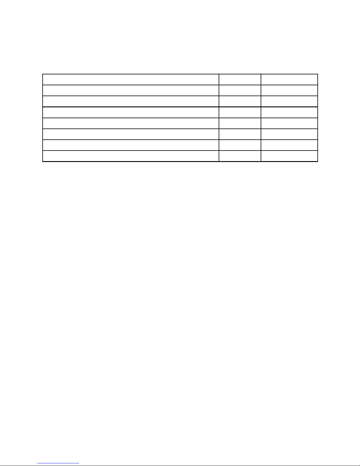
Part number information
Table 1. Ordering part numbers and feature codes
Description Part number Feature code
IBM 1x8 Console Switch 17353LX Not applicable
IBM 2x16 Console Switch 17354LX Not applicable
IBM Local 2x8 Console Manager (LCM2) 17351GX Not applicable
IBM USB Conversion Option (UCO) 43V6147 1735HC1 fc 3756
IBM USB Conversion Option (UCO) 4-pack 39M2895 Not available
IBM Long KVM Conversion Option (KCO) 39M2897 1735HC1 fc 3754
IBM Virtual Media Conversion Option (VCO) 39M2894 1735HC1 fc 3758
The IBM 1x8 Console Switch includes the following items:
One 1x8 Console Switch
Mounting hardware for EIA space for rack sidewall compartment
One 1U filler panel
One C13/C14 rack power cable
Eight terminators for daisy-chaining configurations
Installation publications and warranty
The IBM 2x16 Console Switch includes the following items:
One 2x16 Console Switch
Mounting hardware for EIA space for rack sidewall compartment
One 1U filler panel
One C13/C14 rack power cable
16 terminators for daisy-chaining configurations
Installation publications and warranty
The IBM Local 2x8 Console Manager includes the following items:
One 2x8 Console Switch
Mounting hardware for EIA space for rack sidewall compartment
One 1U filler panel
One C13/C14 rack power cable
Eight terminators for daisy-chaining configurations
One 6 ft CAT-5 cable
Installation publications and warranty
Each of the Conversion Option parts listed in Table 1 ships with:
One Conversion Option
One CAT-5 cable
Installation publications and warranty
IBM Rack-Based Local Console Switches 2
Page 3
Features
The KVM console switches enable you to share one workspace (keyboard, mouse, and display) across
many target systems. The target systems are connected to the console switch via CAT-5 cables and the
appropriate conversion option at the target end. Conversion options are available with either USB or PS/2
connectors. In addition, multiple target systems can be daisy-chained together using CAT-5 cables, and
then all connected to the console switch using the one cable, thereby eliminating a lot of cable clutter.
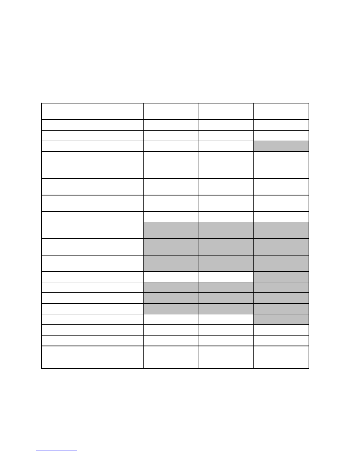
Table 2. Comparison of features
Feature IBM 1x8 Console
Switch
Number of local concurrent users 1 2 2
Local user connections - KVM VGA + PS/2 or USB VGA + PS/2 or USB VGA + PS/2 or USB
Local user connections - extra USB No No Yes (2)
Remote user connections Not available Not available Not available
Maximum number of target systems Direct (ARI ports)
Maximum number of target systems Daisy-chained
Maximum number of target systems Tiered configuration
Maximum video resolution 1280 x 1024 @ 75 Hz 1280 x 1024 @ 75 Hz 1280 x 1024 @ 75 Hz
Support for USB Conversion Option, UCO
(43V6147 and 39M2895)
Support for KVM (PS/2) Conversion
Option, KCO (39M2897)
Support for Virtual Media Conversion
Option, VCO (39M2894)
8 16 8
128 256 128
128 256 512 / 2048‡
Yes Yes Yes
Yes Yes Yes
Yes* Yes* Yes
IBM 2x16 Console
Switch
IBM 2x8 LCM2
Virtual media No No Yes
OSCAR user interface Yes Yes Yes
Password protection Yes Yes Yes
Serial port Yes Yes Yes
Ethernet port No No Yes†
Firmware upgrades to the console switch Via serial port Via serial port Via serial & Ethernet
Firmware upgrades to the COs Via OSCAR interface Via OSCAR interface Via OSCAR interface
Input power 100-240V, 50/60 Hz
12.5 W consumption,
40 W max
* The 1x8 and 2x16 console switches support the use of the Virtual Media Conversion Option (VCO) for connectivity,
but they do not support the use of remote virtual media. The use of the VCO with these console switches represents a
lower-cost alternative to the UCO if chaining is not required.
‡ 2048 target systems in a tiered configuration when front-ended with a Global Console Manager console switch.
† The Ethernet port of the LCM2 is for firmware updates only.
IBM Rack-Based Local Console Switches 3
100-240V, 50/60 Hz
12.5 W consumption,
40 W max
100-240V, 50/60 Hz
12.5 W consumption,
40 W max
Page 4

Number of local concurrent users :
The 1x8 and LCM2 console switches enable a single local user to access any attached servers. The 2x16
console switch enables two simultaneous users to access attached servers. With the 2x16 console
switch, connections can be preemptive or cooperative. In preemptive mode, the connection between one
local user and a target device is disconnected, without warning, if the second local user selects the same
target device. In cooperative mode, the local user maintains the connection to a target device if another
user selects the same target device. The way the keyboard and mouse are shared is configurable via the
OSCAR interface.
Local user connections :
Local displays are connected to the console switch using VGA analog connections. Keyboard and mouse
can be either PS/2-style connections or USB. Two USB ports are provided for mouse and keyboard
connections. The LCM2 includes two additional USB ports for the attachment of devices such as optical
drives or memory keys. These devices can be made available on remote target systems provided Virtual
Media Conversion Options are used to connect to those target systems. Note, however, that the Virtual
Media Conversion Option does not support chaining of target systems.
Target systems:
Each console switch has 8 or 16 target system ports (known as analog rack interface or ARI ports). These
can be directly attached to systems with the appropriate USB or PS/2 conversion option connector on the
end. These connections use standard CAT-5 cables. You can increase the number of connected target
systems by two methods: chaining or a tiered arrangement of switches (more about these below). Both
methods mean that each of the 8 or 16 ports will have multiple systems connected to it. You can mix
connection methods.
Conversion Options:
These are cables-connector combinations that are connected between the CAT-5 cables from the
console switches to the target systems. Figure 2 shows the three conversion option cables available for
use with the console switches.
Shown on the left in Figure 2 are the KVM Conversion Option (KCO) with VGA and PS/2-style mouse and
keyboard connections, and the USB Conversion Option (UCO) with VGA and USB connections.
The Virtual Media Conversion Option shown on the right in Figure 2 supports the virtual media capability
of the LCM2; however, it does not support chaining. More about virtual media in the heading Virtual Media
later in this document.
IBM Rack-Based Local Console Switches 4
Page 5

Figure 2. IBM KVM Conversion Option, KCO (top) and IBM USB Conversion Option, UCO (bottom)
The built-in memory of each connection option helps simplify configuration by assigning and retaining
unique server identification codes for each attached server. This integrated intelligence enhances security
and helps prevent unauthorized access to a server through cable manipulation. The connection option is
powered directly from the server, providing Keep Alive functionality even if the server is not powered on.
OSCAR user interface :
The On-Screen Configuration and Activity Reporting (OSCAR) user interface is the way users access the
target systems. Accessible by default via the Print Screen key, it has menus to configure the switching
system and to select computers. You can list target devices by unique name, electronic ID, or port
number.
Security:
All of these local console switches support the use of a password for access to the target systems. The
OSCAR interface enables you to configure a screen saver password; you are prompted for the password
after a configurable time-out, when the user logs out, or when the switch is powered on. This prevents
unauthorized access to the target systems.
In addition, the OSCAR interface on the 1x8 and 2x16 console switches lets you configure up to four user
accounts, and you can specify which target systems each of those accounts can access.
Firmware updates:
All of these local console switches can have their firmware updated. The 1x8 and 2x16 console switches
enable the updating of firmware via the serial port. The LCM2 lets you update the firmware using a serial
port console and a TFTP server using the Ethernet connection. With all of these console switches, once
the console switch firmware is updated, the firmware of the Conversion Options can be performed via the
OSCAR user interface, either individually or all Conversion Options can all be upgrade simultaneously.
Automatic updates of the Conversion Options is also possible.
IBM Rack-Based Local Console Switches 5
Page 6

Connections
Figure 3 shows the connections on the 2x16 console switch. The 1x8 console switch has identical
connections except it only has eight ARI ports, whereas the 2x16 has 16 ARI ports.
Figure 3. Connections on the 2x16 Console Switch
Figure 4 shows the connections on the LCM2 console switch. The LCM2 offers two extra USB ports for
each local user for the virtual media feature plus an Ethernet port for firmware updates.
Figure 4. Connections on the LCM2 Console Switch
IBM Rack-Based Local Console Switches 6
Page 7

Chaining
IBM’s cable chaining solution enables users to manage a "daisy chain" of multiple servers through a
single connection to the console switch, replacing many long cables with just a few short ones, simplifying
rack management, helping lower cabling cost and reducing setup, diagnostic, and maintenance times.
The daisy-chain connectivity has the added advantage of thin, flexible, industry-standard CAT5 cabling
and standard RJ-45 connectors, eliminating the need for one-to-one, dedicated cable connections
between KVM switch ports and managed devices. This cable chaining solution allows up to 16 target
systems to be chained together and connected to one port on the switch.
Figure 5 shows an example of chaining three target systems from one port on the console switch. Each
conversion option part number includes a CAT-5 cable to connect it to either the console switch or its
neighbor conversion option. The console switch includes the terminator needed at the end of the daisy
chain.
Figure 5. Chaining using USB Conversion Options
IBM Rack-Based Local Console Switches 7
Page 8

Tiered consoles
You can tier multiple rack console switches to enable access to additional servers. In a tiered system, an
ARI port on the main rack console switch connects to the ACI port of a tiered rack console switch (see
Figure 3 for locations of these ports). Consider a tiered configuration if you want to manage servers
connected to multiple switches from one central location. For example, you could have a primary 2x16
console switch with 16 switches tiered underneath it that all have servers chained on their ports.
Figure 6 shows an example of tiered consoles.
Figure 6. Tiered consoles
Maximum configurations are as follows:
The 1x8 Console Switch can scale to support up to a total of 128 target systems by connecting
additional console switches to each of the 8 ARI ports on the 1x8 switch. Only one level of tiering is
supported.
The 2x16 Console Switch can scale to support up to a total of 256 target systems by connecting
additional console switches to each of the 16 ARI ports on the 1x8 switch. Only one level of tiering is
supported.
The LCM2 Console Switch can scale to support up to a total of 512 target systems by connecting
additional console switches to each of the 8 ARI ports on the LCM2 switch. One, two, or three levels
of tiering are supported.
When using the IBM GCM console switch as the primary switch in a tiered environment, the KVM
switching system can scale to support 2048 target systems
IBM Rack-Based Local Console Switches 8
Page 9

Virtual Media
The LCM2 supports virtual media when the target systems are connected using the Virtual Media
Conversion Option (VCO), part number 39M2894. You can use virtual media support to connect USB 2.0
media devices to the console switch using one of the four USB ports and make those devices available to
any connected system. With this feature, you can install software; install, upgrade, or recover the
operating system; update the BIOS code; or boot the target system from a USB drive.
Control of how the USB device is connected to the target system is managed through the OSCAR user
interface. OSCAR presents the following configuration options:
Locked or Unlocked: In Locked mode, when the user is disconnected from a target system, the virtual
media is also disconnected. If Unlocked is selected, then when the user disconnects, the media
device is still seen by the target system.
Reserved: By checking this option in the OSCAR user interface, the virtual media connection can be
accessed only by your user name and no other user can connect to the virtual media connection.
CD-ROM: Establishes a virtual CD connection to the target system.
Mass Storage: Establishes a virtual mass-storage device connection to the target system.
Write Access: With this option, you can specify whether the target system can write to the USB device
(assuming it is writable).
Note that USB ports are assigned to a single virtual media session and cannot be independently mapped.
This means you cannot map one USB device to one target system and another USB device to another
target system.
Physical specifications
1x8 and 2x16 console switches:
Height: 43 mm (1.7 inches)
Width: 432 mm (17 inches)
Depth: 165 mm (6.5 inches)
Weight: 3.6 kg (8 lb)
LCM2 console switch:
Height: 43 mm (1.7 inches)
Width: 432 mm (17 inches)
Depth: 203 mm (8 inches)
Weight: 2.6 kg (5.75 lb)
Warranty
Each console switch has a three-year limited warranty when installed in an IBM rack or used with IBM
servers.
IBM Rack-Based Local Console Switches 9
Page 10

Supported systems
The console switches are supported connected to the IBM BladeCenter chassis listed in Table 3.
Table 3. Supported IBM BladeCenter chassis
I/O module
IBM 1x8 Console Switch 17353LX Y Y Y Y Y
IBM 2x16 Console Switch 17354LX Y Y Y Y Y
IBM Local 2x8 Console Manager (LCM2) 17351GX Y Y Y N Y
Part number
The console switches are supported connected to the IBM System x servers listed in Table 4.
Table 4. Supported IBM System x servers
1x8 Console
Switch
2x16 Console
Switch
LCM2 Console
Switch
N Y Y Y Y Y Y N Y Y Y Y Y N Y Y Y Y Y
N Y Y Y Y Y Y N Y Y Y Y Y N Y Y Y Y Y
Y Y Y Y Y Y Y N Y Y Y Y Y N Y Y Y Y Y
See the IBM ServerProven Web site for the latest compatibility information:
http://ibm.com/servers/eserver/serverproven/compat/us/.
IBM Rack-Based Local Console Switches 10
Page 11

Related publications and links
For more information refer to these documents and Web links:
IBM Console Switches product page
http://www.ibm.com/systems/x/hardware/options/kvm.html
Avocent downloads page
http://ibm.avocent.com/index.php/home/downloads
Installation and User's Guide - 1x8 and 2x16 console switches
http://www.ibm.com/support/docview.wss?uid=psg1MIGR-5076639
Installation and User's Guide - LCM2 console switch
http://www.ibm.com/support/docview.wss?uid=psg1MIGR-62083
IBM Redbooks at-a-glance guide for the IBM 1U 17-inch and 19-inch Flat Panel Console Kits
http://www.redbooks.ibm.com/abstracts/tips0731.html?Open
IBM US Announcement Letter - 1x8 and 2x16 console switches
http://ibm.com/common/ssi/cgi-bin/ssialias?infotype=dd&subtype=ca&&htmlfid=897/ENUS107-158
IBM US Announcement Letter - LCM2 console switch
http://ibm.com/common/ssi/cgi-bin/ssialias?infotype=dd&subtype=ca&&htmlfid=897/ENUS105-438
IBM Rack-Based Local Console Switches 11
Page 12

Notices
©
This information was developed for products and services offered in the U.S.A.
IBM may not offer the products, services, or features discussed in this document in other countries. Consult your local
IBM representative for information on the products and services currently available in your area. Any reference to an
IBM product, program, or service is not intended to state or imply that only that IBM product, program, or service may
be used. Any functionally equivalent product, program, or service that does not infringe any IBM intellectual property
right may be used instead. However, it is the user's responsibility to evaluate and verify the operation of any non-IBM
product, program, or service. IBM may have patents or pending patent applications covering subject matter described
in this document. The furnishing of this document does not give you any license to these patents. You can send
license inquiries, in writing, to:
IBM Director of Licensing, IBM Corporation, North Castle Drive, Armonk, NY 10504-1785 U.S.A.
The following paragraph does not apply to the United Kingdom or any other country where such provisions
are inconsistent with local law: INTERNATIONAL BUSINESS MACHINES CORPORATION PROVIDES THIS
PUBLICATION "AS IS" WITHOUT WARRANTY OF ANY KIND, EITHER EXPRESS OR IMPLIED, INCLUDING, BUT
NOT LIMITED TO, THE IMPLIED WARRANTIES OF NON-INFRINGEMENT, MERCHANTABILITY OR FITNESS
FOR A PARTICULAR PURPOSE. Some states do not allow disclaimer of express or implied warranties in certain
transactions, therefore, this statement may not apply to you. This information could include technical inaccuracies or
typographical errors. Changes are periodically made to the information herein; these changes will be incorporated in
new editions of the publication. IBM may make improvements and/or changes in the product(s) and/or the program(s)
described in this publication at any time without notice.
Any references in this information to non-IBM Web sites are provided for convenience only and do not in any manner
serve as an endorsement of those Web sites. The materials at those Web sites are not part of the materials for this
IBM product and use of those Web sites is at your own risk.IBM may use or distribute any of the information you
supply in any way it believes appropriate without incurring any obligation to you. Information concerning non-IBM
products was obtained from the suppliers of those products, their published announcements or other publicly
available sources. IBM has not tested those products and cannot confirm the accuracy of performance, compatibility
or any other claims related to non-IBM products. Questions on the capabilities of non-IBM products should be
addressed to the suppliers of those products. This information contains examples of data and reports used in daily
business operations. To illustrate them as completely as possible, the examples include the names of individuals,
companies, brands, and products. All of these names are fictitious and any similarity to the names and addresses
used by an actual business enterprise is entirely coincidental.
Any performance data contained herein was determined in a controlled environment. Therefore, the results obtained
in other operating environments may vary significantly. Some measurements may have been made on
development-level systems and there is no guarantee that these measurements will be the same on generally
available systems. Furthermore, some measurement may have been estimated through extrapolation. Actual results
may vary. Users of this document should verify the applicable data for their specific environment.
COPYRIGHT LICENSE:
This information contains sample application programs in source language, which illustrate programming techniques
on various operating platforms. You may copy, modify, and distribute these sample programs in any form without
payment to IBM, for the purposes of developing, using, marketing or distributing application programs conforming to
the application programming interface for the operating platform for which the sample programs are written. These
examples have not been thoroughly tested under all conditions. IBM, therefore, cannot guarantee or imply reliability,
serviceability, or function of these programs.
Copyright International Business Machines Corporation 2010. All rights reserved.
Note to U.S. Government Users Restricted Rights -- Use, duplication or disclosure restricted by
GSA ADP Schedule Contract with IBM Corp.
IBM Rack-Based Local Console Switches 12
Page 13

This document was created or updated on March 10, 2010.
Send us your comments in one of the following ways:
Use the online Contact us review form found at:
ibm.com/redbooks
Send your comments in an e-mail to:
redbook@us.ibm.com
Mail your comments to:
IBM Corporation, International Technical Support Organization
Dept. HYTD Mail Station P099
2455 South Road
Poughkeepsie, NY 12601-5400 U.S.A.
This document is available online at
http://www.ibm.com/redbooks/abstracts/tips0730.html
.
Trademarks
IBM, the IBM logo, and ibm.com are trademarks or registered trademarks of International Business
Machines Corporation in the United States, other countries, or both. These and other IBM trademarked
terms are owned by IBM at the time this information was published. Such trademarks may also be
registered or common law trademarks in other countries. A current list of IBM trademarks is available on
the Web at http://www.ibm.com/legal/copytrade.shtml
The following terms are trademarks of the International Business Machines Corporation in the United
States, other countries, or both:
BladeCenter®
IBM®
Redpaper™
Redbooks (logo)®
ServerProven®
System x®
Other company, product, or service names may be trademarks or service marks of others.
IBM Rack-Based Local Console Switches 13
 Loading...