

Page 1
RS/6000 7044 Model 170
Technical Overview and Introduction
February 24, 2000
Volker Haug
Jeanine Indest
Scott Vetter
Internationa l Techn ical Su ppor t Organ iza tion
Austin, TX
IBM
© Copyright IBM Corp. 2000
Page 2

RS/6000 7044 Model 1 70 Te chnic al Overv iew
Page 3

RS/6000 7044 Model 170 Technical Overview
The IBM RS/6000 family is a scalable, software-compatible line of RISC UNIX
workstations, servers, and supercomputers powered by IBMs AIX operating
system. On February 7, 2000, IBM announced two exciting additions to this
family, the 44P Models 170 and 270.
This paper provides a brief history, a general description, and a technical
overview of the 44P Model 170 including: the 64-bit copper technology of the
POWER3-II processor, the error checking and correcting (ECC) memory
subsystem, the advanced packaging design, the built-in service processor, the
sophisticated graphics support, and other selected features.
History
The original 43P Model 140 graphics workstation and entry-level workgroup
server was introduced on October 8, 1996. This uniprocessor system offered a
variety of processing speeds and features. The 43P Model 240, introduced at the
same time, was the first RS/6000 workstation/workgroup server to offer
expandability to 2-way symmetric multiprocessing (SMP). On October 5, 1998,
IBM introduced both the 43P Model 150 and the Model 260. The Model 150
offered enhanced performance over the Model 140. The Model 260 is a 1- or
2-way SMP system utilizing the 64-bit 200 MHz POWER3 processor.
General Description
The RS/6000 44P Models 170 and 270 extend the IBM line of powerful and
affordable workstation/workgroup servers with state-of-the-art, 64-bit, copper
POWER3-II processors. The 44P server family, manufactured in Rochester,
Minnesota, USA and Santa Palomba, Italy, offers ideal solutions for both
high-performance 2D or 3D CAD/CAM users and companies that require a
compact system for commercial computing solutions, such as Lotus Notes,
business intelligence, Web server applications, software development, and
firewall applications.
Minimum Configuration and Optional Features
The Model 170 minimum configuration includes a single POWER3-II 64-bit
processor with a choice of either a 333 MHz processor with 1 MB of Level 2 (L2)
cache or a 400 MHz processor with 4 MB of L2 cache. Currently, the 400 MHz
processor option is the fastest POWER3-II processor available in the RS/6000
product family. Each processor is equipped with 64 KB of data and 32 KB of
instruction Level 1 (L1) cache. A 10/100 Mbps Ethernet controller, one Ultra SCSI
controller, one external Ultra2 SCSI controller, and the service processor are
integrated on the system planar.
In addition, the Model 170 has 256 MB of ECC synchronous dynamic random
access memory (SDRAM), three disk bays, three media bays, a 9.1 GB 1” Ultra
SCSI disk drive, six PCI slots, a 32X CD-ROM drive, a 1.44 MB 3.5-inch dis kette
drive, and an operator panel. The operator panel has a 2 x 16 backlit LCD for
system status and diagnostic information. Microphone and headphone jacks are
built into the operator panel. The following ports are included: keyboard, mouse,
© Copyright IBM Corp. 2000 1
Page 4
Physical Package
Ethernet (AUI and RJ45), parallel, two serial (9-pin D-shell), tablet (for use with
legacy input devices), Ultra2 SCSI VHDC, and stereo/audio.
To connect external SCSI devices to the Ultra2 SCSI adapter’s VHDC, order
# 2118 (mini-68 pin VHDC to 68 pin). This 0.3 m long cable (P/N 76H0518) is not
included with the minimum system configuration.
The Model 170 offers many optional features. The media bay can hold a second
CD-ROM device, a 4 mm or 8 mm tape drive, or a SCSI disk drive. A media bay
mounting kit is required to install a SCSI disk drive in the media bay. A variety of
optional input devices are offered including: keyboard, mouse, Spaceball 3D
input device, and a Magellan 3D (Spacemouse) input device.
The 44P Model 170 has an elegant and compact mini-tower design that was
originally created for the PC IntelliStation deskside mini-tower, then revised for
RS/6000 duty. The system dimensions are 19.25” H x 7.9” W x 20.25” D (490 mm
x 200 mm x 515 mm). The system weight ranges from 39 lbs to 45 lbs (17.7 kg to
20.4 kg). This system is not available in a desktop or rack mounted package.
Operating environment requirements are available in announcement information.
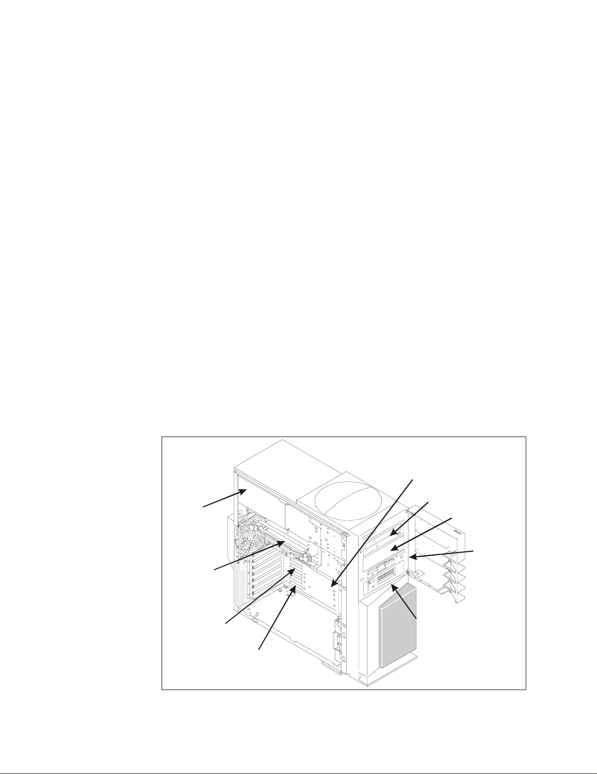
Figure 1 shows an internal view of the system with the side cover and cover
support bridge removed. The CD-ROM drive, diskette drive, and one disk drive
are preinstalled with each system. The remaining 5.25” media bay and two 3.5”
disk bays are available for system expansion. Also, a keylock is located on the
back of each system.
To open the side cover, unlock, pull the cover detent away from the rear of the
unit, then slide the cover toward the front of the system unit to release the tabs.
Three Di sk
Bays
Power
Supply
CPU
Card
Memory
Cards
PCI
Cards
CD-ROM
2nd Media
Bay
Diskette
Operator
Panel
Figure 1. 7044 170 - M echa nical V iew
2 RS/6000 7044 Model 170 Techni ca l Overview
Page 5
System Upgrade
g
There are no system model upgrade conversions available for the 44P Model
170. Processor and memory expansion options are available for this system. The
Model 170 is designed for customer setup of the machine and for the subsequent
addition of most features (adapters and devices).
Architecture and Technical Information
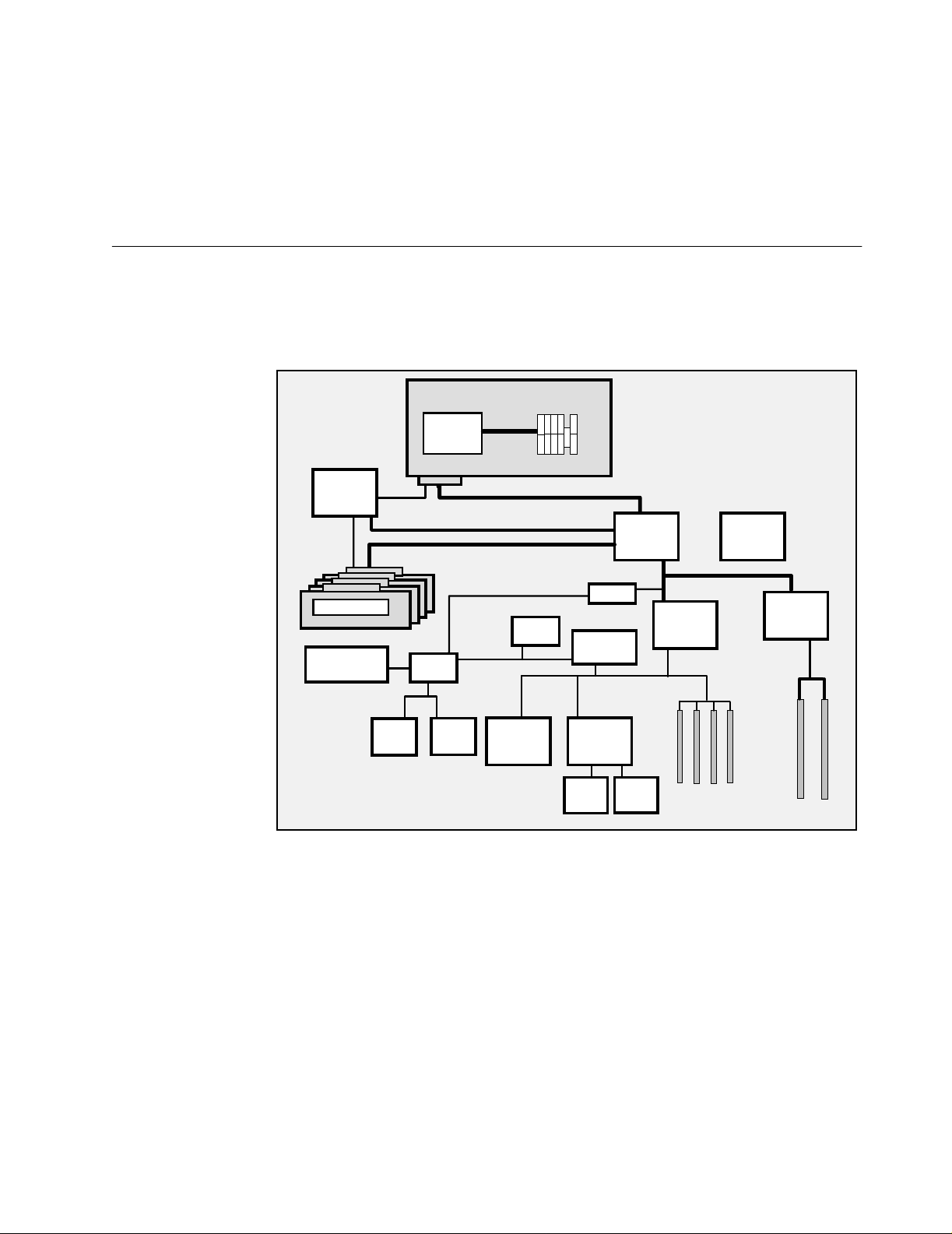
A diagram of the system architecture and logic flow for a 400 MHz system is
shown in Figure 2. The 333 MHz system differences and a general discussion of
this diagram is provided in the following sections.
Addr/Cntl
Memory
Address
Memory Modules
256 MB -2 GB Total
Integrated Service
Processor
Processor Card
POWER3-II
400 MHz
6xx Data Bus 16 Bytes @ 100 MHz
6xx Address Bus 100 MHz
Memory Data Bus 16 Bytes @ 100 Mhz
SP
Interface
Audio
Super
I/O
32 Bytes
@ 200 MHz
10/100
Ethernet
Boot
ROM
4 MB L2
ISA Bridge
Ultra-SCSI
External
Ultra2
Arbiter
Data
Internal
Ultra
PCI Brid
S6
System Planar
System
Clock
2 PCI Slots
64-bit
50 MHz
3.3v
4 PCI Slot s
32-bit
33 MHz
5.0v
PCI Bridge
S2
S1
e
S3
S4
S5
Figure 2. Model 170 - System Logic Flow Diag ra m
Processor and C ache
The 44P Model 170 is the most affordable 64-bit system that IBM has introduced
and uses the POWER3-II processor. The POWER3-II processor is designed for
high-performance commercial and graphical computing applications. The
processor allows for concurrent operation of up to ei ght ins tructions per c ycle
(three fixed-point instructions, two floating point instructions, two load/store
instructions, and one branch instruction). Increasing the number of
simultaneously executed instructions results in better system performance
especially with applications that are optimized to take advantage of this
capability.
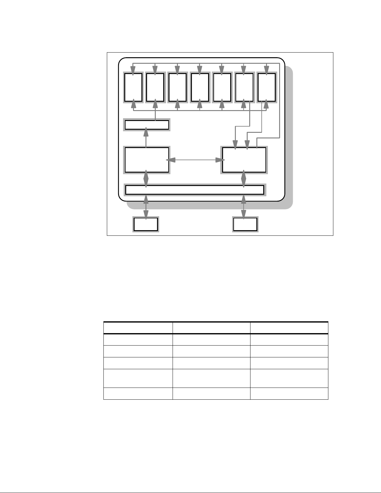
Figure 3 is a diagram of the functional components of this processor, shown
attached to the cache and bus configuration of a 400 MHz Model 170.
RS/6000 7044 Model 170 Technical Overview 3
Page 6
Unit
Floating
Point
Unit
FPU2
Floating
Point
FPU1
Branch/Dispatch
32 KB, 128-way 64 KB, 128-way
Fixed
Point
Unit
FXU1
Branch history table 2048 entries
Branch target cache 256 entries
Fixed
Point
Unit
FXU2
Fixed
Point
Unit
FXU3
LD/ST
Unit
LS1
LD/ST
Unit
LS2
CPU registers:
32 x 64-bit integer
(Fixed Point)
32 x 64-bit FP
(Floating Point)
Register buffers for
register renaming:
24 FP
16 Integer
Memory Mgmt Uni t
Instruction Cache
BIU
Direct
Mapped
IU
32
Bytes
32 Bytes
@ 200 MHz= 6.4 GB/s
L2 Cache
4 MB
Bus Interface Unit L2 Control, Clock
Memory Mgmt Unit
Data Cache
DU
32
Bytes
16 Bytes
@ 100 MHz=1.6 GB/s
6XX Bus
Figure 3. Model 170 - POW ER3 -II 400 MHz Blo ck Diagr am
POWER3 Versus POWER3-II Processors
The processor functional diagram of the POWER3 and the POWER3-II are
similar; however, the use of copper in the POWER3-II represents a new
generation of processing power. A single POWER3-II chip contains about 400
meters of copper wiring. Table 1 lists some of the differences between the
POWER3 and the POWER3-II processors. Also, the chart indicates the direction
being taken by this technology.
Table 1. Differences between POWER3 versus POWER3-II
Description POWER3 POWER3-II
Chip Die Size 270 mm
2
163 mm
2
Transistors 15 million 23 million
Power Avg/Max 39/46W@200 MHz 28W/36W@400 MHz
CMOS Technology 6S2, 5 layers metal 7S, 6 layers metal, copper
Lithography 0.25
4 RS/6000 7044 Model 170 Techni ca l Overview
interconnect
µm 0.22 µm
Page 7

Copper and CMOS Technology
The use of copper in chip design addresses several or the aspects that inhibit
performance: power load, generated heat, clock signal distribution, and chip size.
The complexity of the chip design (roughly equated to the number of transistors)
when combined with the lithography process determines the size of the die. The
maze of interconnects between the circuitry over a large die, the voltage required
to drive the circuits, and the clock speed of the chip (how often a circuit changes
state) determines the power load and the heat generated. Heat affects the life of
the chip. Specific areas of a chip, for example, an execution unit, can become
hotter than other areas that operate less frequently and require extensive cooling.
Also, the larger the chip, the more difficult it is to strobe a clock signal over the
entire chip (electricity travels at the fixed speed of light). Because larger chips
also require more area on a wafer, they are more expensive to produce.
Copper is a superior conductor of electricity, compared with the standard
aluminum used previously. This equates to lower electrical resistance (40 percent
less) and allows a smaller wire (interconnects) to handle the same electrical load.
The smaller interconnects within the chip decrease the distance between
components, reduce the heat generated, and decrease the clock skew over the
chip making it possible to raise the clock speed without affecting reliability. This is
particularly useful on the POWER3-II which is an advanced and complex chip
with twice the number of transistors as in a Pentium II.
However, copper does not work well with silicon, the base material of
semiconductor chips. If copper is put directly on silicon, copper atoms migrate
into the silicon, making it virtually useless. IBM researchers found a way to put a
microscopic barrier between the copper and silicon in a way that keeps the
copper from contaminating the silicon, while actually reduces the number of steps
needed to complete a chip. With this development, IBM is able to reduce the
widths of copper wires to about 0.2-microns from the current 0.35-micron width a feat far more difficult to achieve with aluminum.
This technology, called CMOS 7S, is the first to use copper instead of aluminum
to create the circuitry on silicon wafers. This translates into an increased speed of
up to 15 percent in processors that contain copper wires.
CPU Clock Rate
The different processor cards and the processor speeds can be identified by the
SMS Display Configuration menu or by the following AIX command:
lscfg -vp | more
Page down to the Processor Card entry and search for the Prod uct Specificatio n
(ZC) entry. This gives detailed information about:
PS Processor Clock Speed in Hz, ASCII coded hexadecimal
LB L2 Bus Speed in Hz, ASCII coded hexadecimal
SB System Bus Speed in Hz, ASCII coded hexadecimal
NP Number of Processors on Card, ASCII coded hexadecimal
L2 L2 Size in number of Kilobytes, ASCII coded hexadecimal
RS/6000 7044 Model 170 Technical Overview 5
Page 8

Following is an example of the processor card information for a 333 MHz Model
170:
Processor Card :
Part Number.................11K0857
EC Level....................D72830
Serial Number...............L200016008
FRU Number.... .... ... .... .. .00P 2180
Manufacture ID .... ... .... .. .198 0
Version..... .... .... ... .. ...R S6K
Product Specific.(ZC).......PS=0013D92D40,LB=0009EC96A0,
Product Specific.(ZB).......BC=30602,SG=
Physical Location: P1-C1
SB=0005ABC3C9,NP=01,L2=01024,
PF=711,SV=3,VR=2,ER=0000
PS shows the processor speed in hex-number digit (0x0013D92D40 =
333000000 Hz = 333 MHz).
Following is an example of the processor card information for a 400 MHz Model
170:
Processor Card :
Part Number.................11K0864
EC Level....................D72830
Serial Number...............L200016010
FRU Number.... .... ... .... .. .00P 2181
Manufacture ID .... ... .... .. .198 0
Version..... .... .... ... .. ...R S6K
Product Specific.(ZC).......PS=0017D78400,LB=000BEBC200,
Product Specific.(ZB).......BC=30602,SG=
Physical Location: P1-C1
SB=0005F5E100,NP=01,L2=04096,
PF=7D4,SV=3,VR=2,ER=0000
PS shows the processor speed in hex-number digit (0x0017D78400 = 400000000
Hz = 400 MHz).
Level 1 Cache
The Model 170 uses a 64 KB data and 32 KB instruction 128-way set associative
L1 cache. The size of both data and instruction cache reduces the number of
cache misses, results in more cache hits, and maximizes performance. Both data
and instruction cache are parity protected.
Level 2 Cache
The 44P Model 170 processor card has either 1 MB (333 MHz) or 4 MB
(400 MHz) of L2 cache located on the processor card. L2 cache is used to lower
the time spent accessing memory data and increase perfor mance. The L2 cache
extends L1 cache benefits by adding more cache to the memory pipeline.
The speed of the L2 cache is dependent upon the processor speed. The L2
cache speed for the 333 MHz processor is 167 MHz (2:1 ratio) and for the 400
MHz processor is 200 MHz (2:1 ratio).
The L2 cache uses a direct mapped cache methodology. There is a dedicated
external interface to the L2 cache not shared with the 6XX bus. This allows
concurrent access to both the L2 cache and the 6XX bus.
6 RS/6000 7044 Model 170 Techni ca l Overview
Page 9

Memory
The system supports from 256 MB to 2 GB of ECC SDRAM using a 128-bit wide
memory bus. Memory bus speed varies dependent upon processor selection. The
enhanced memory controller uses a 95.1 MHz memory bus speed on the 333
MHz system and a 100 MHz memory bus speed on the 400 MHz system.
There are four memory slots available in the 44P Model 170. The Dual Inline
Memory Modules (DIMMs) are ordered and installed in pairs. The following
options are currently available:
• 256 MB (2 X 128 MB) SDRAM DIMMs (# 4110)
• 512 MB (2 X 256 MB) SDRAM DIMMs (# 4119)
• 1024 MB (2 X 512 MB) SDRAM DIMMs (# 4121)
SDRAM DIMMs are used in most of the RS/6000 systems currently available.
Reference current feature codes and part numbers to determine if DIMMs may be
interchanged between systems. Figure 4 shows the memory slot location for this
system.
J10
J2
J9
J1
Figure 4. 7044 170 - M emo ry Location Di agr am
Memory modules must be installed in pairs using the correct slot configuration.
Slots J1 and J2 are a pair and slots J9 and J10 are a pair.
RS/6000 7044 Model 170 Technical Overview 7
Page 10

Memory Boot Time Deconfiguration
Memory boot time deconfiguration is a function implemented in the service
processor firmware to remove a memory segment or DIMM from the system
configuration at boot time. The objective is to minimize system failures or data
integrity exposure due to faulty memory hardware.
The memory segment or DIMMs that are deconfigured remain offline for
subsequent reboots until the faulty memory hardware is replaced. This requires
powering off the system. Then, this function gives the user the option to manually
deconfigure or re-enable a previously deconfigured memory segment/DIMM
using the service processor menus.
System Buses
Memory can also be decreased through AIX using the
useful for certain benchmark simulations.
Note
Memory cards should be physically removed only when the power is turned off
to the entire system.
The system bus is controlled by a highly specialized set of custom chips. One
handles addressing and synchronization, the other moves data to and from the
processor (the 6XX bus), memory (memory bus), and the I/O (I/O bus). The 6XX
bus is a 128-bit bus running at a clock speed of either 100 MHz, a 4:1 ratio, when
featured with a 400 MHz processor (which results in a peak data throughput of
1600 MB per second) or 95.1 MHz, a 7:2 ratio, when featured with a 333 MHz
processor.
The 6XX bus is optimized for high-performance and multiprocessing
performance. The bus is fully parity checked and each memory request is range
checked and positively acknowledged for error detection. Any error will cause a
machine check condition and is logged in the AIX error log.
The 6XX and memory buses operate at the same speed, 128-bit width, and have
the same throughput. Their speed is automatically determined by the speed of
the processor installed. Data and address buses operate independently in true
split transaction mode and are pipelined so that new requests may be issued
before previous requests are completed.
rmss command. This is
PCI Bus, Slots, and Adapters
The Model 170 is compliant with Revision 2.1 of the peripheral component
interconnect (PCI) specifications and implements dual PCI bridge chips in a peer
configuration. One PCI bridge chip provides a 32-bit interface operating at 33
MHz for four PCI slots and the other PCI bridge chip implements a 64-bit bus
operating at 50 MHz for two PCI slots. Slots one and two are 64-bit, 50 MHz, 3.3v
slots and slots three, four, five, and six are 32-bit, 33 MHz, 5.0v slots. All slots in
the Model 170 accept full-sized PCI adapters. The 64-bit slots are physically
keyed to accept either universal or 3.3v cards only. 5.0v cards will not seat in the
card slots. Detailed information is available in the announcement information for
this system.
8 RS/6000 7044 Model 170 Techni ca l Overview
Page 11

A variety of PCI adapter, controller, graphics accelerator, SCSI, LAN, WAN,
asynchronous, and SSA cards, to name a few, may be installed in the 44P Model
170. Specific information on selected adapters is provided in the following
sections:
LAN Adapters
The Model 170 can be connected through the LAN. It supports the following types
of PCI adapters, which are all supported for NIM installations (use
chrp as
platform type):
• 25/155 Mbps ATM
• Gigabit Ethernet
• 10/100 Mbps Ethernet
• 4/16 Mbps token ring (100 Mbps token ring is not available at time of
publication)
Graphics Accelerators
A choice of four graphics accelerators are offered for the Model 170. The
GXT130P is an entry-price 2D adapter suitable for business graphics or Internet
applications. The GXT300P is a high-performance, 24-bit color, 2D graphics
accelerator with 3D capability via Softgraphics functions found in the graPHIGS
and OpenGL APIs.
The GXT2000P and GXT3000P are full 24-bit capable accelerators and support
the simultaneous execution of both graPHIGS and OpenGL applications.
Currently, the GXT3000P is the most powerful graphics accelerator available.
The maximum number of graphics accelerators supported in this system is four
(the GXT3000P is limited to a maximum of two). Refer to the limitations section of
the announcement for details on limitations associated with graphic accelerators
for this system.
A graphics accelerator is not required in the minimum configuration. In order to
attach an ASCII display, either # 3926 or both # 2934 and # 3925 must be
ordered to provide connection. A 9-25 pin serial connector is not included by
default. Determine if the ASCII display you wish to install requires an interposer,
adapter, or both to avoid installation problems.
SSA Adapters
The Advanced SerialRaid Plus Adapter (# 6230) is available for the Model 170.
Optional features include the 128 MB DRAM Option Card (# 6231) and the 32 MB
Fast-Write Cache Option Card (# 6235).
Hot Plug PCI Adapters Capabiliti es
Hot plug PCI adapter capabilities are not supported on the Model 170.
Hot plug PCI capabilities are, however, available within the RS/6000 product line.
The RS/6000 SP Expansion I/O Units support hot plug for selected PCI adapters.
This function enables the maintenance of these adapters without powering of f the
SP Expansion I/O Unit or the associated SP POWER3 SMP High Node. This
function requires AIX Version 4.3.3 with APAR IY06844.
RS/6000 7044 Model 170 Technical Overview 9
Page 12

Internal Disk Bays and Media Bays
The disk bays provide from 9.1 GB to 72.8 GB of internal storage space and are
populated with a combination of the following disk drives:
• 9.1 GB 1" Ultra SCSI Hard Disk Drive (# 2908)
• 18.2 GB 1" Ultra SCSI Hard Disk Drive (# 2909)
• 9.1 GB 10 K RPM Ultra SCSI Hard Disk Drive (# 3027)
• 18.2 GB 10 K RPM Ultra SCSI Hard Disk Drive (# 3102)
Note
The 18.2 GB 10 K RPM Ultra SCSI disk drive is not supported for installation in
the media bay, but is allowed in the disk bay.
Service Processor
The Model 170 includes an integrated service processor that is designed to
provide an immediate means to diagnose, check status, and sense operational
conditions of a remote system, even when the main processor is unavailable.
The service processor is a Motorola 68307 microprocessor. The flash memory
used for the storage of the service processor programs is 1 MB and 512 KB of
SRAM memory is used for program execution.
Selected Service Processor Functions
Additional informational is provided for the following selected functions:
Fast Boot
Selecting Fast Boot results in several diagnostic tests being skipped and reduces the
time for booting. This function has to be activated through the Service Processor
menu. (The SXX series of enterprise servers use the operator panel to
enable/disable Fast Boot.)
There is a easy way to check if Fast Boot is enabled without entering the Service
Processor menu. If Fast Boot is enabled no spinner will appear at the Service
Processor checkpoint E0B0. With the Slow Boot enabled, a spinner appears at
E0B0. A spinner is a single text position on the operator LCD that cycles through
the characters
|,/,-, and \ symbolically representing the passage of time.
Memory Boot Time Deconfiguration
Memory Boot Time Deconfiguration gives you the option of deconfiguring
memory without removing it physically. For more detailed information, see the
section on “Memory Boot Time Deconfiguration” on page 8.
Boot Mode Menu
The Boot Mode menu allows selection of the following boot options:
• Boot to SMS Menu
• Service Mode Boot from Saved List
• Service Mode Boot from Default List
• Boot to Open Firmware
10 RS/6000 7044 Model 17 0 Techn ical Over view
Page 13

Miscellaneous
The following general information is included for convenience:
DVD Support
Currently, Digital Versatile Disc (DVD) drives are not supported in RS/6000
systems.
ISA Support
The Model 170 does not support industry standard architecture (ISA) adapters.
USB Support
The Model 170 does not have integrated Universal Serial Bus (USB) support and
no USB adapters are currently available for use in RS/6000s.
Boot Options and Limitations
Detailed information about boot options for internal and external storage devices
is included in the subsequent sections:
Internal Devices
Boot support is available for every internal SCSI disk.
External Device s
Table 2 provides a map that enables you to determine if boot is supported in
external storage devices.
Table 2. Boot Support - Exte rnal De vice s
Does the PCI card have RAI D functio nality?
yes no
Card is seen as a controller
no boot support
Card is seen as a adapter
Does the external device have RAID functionality?
yes no
no boot support (except
Advanced SerialRAID Plus
Adapter
1
)
boot support
Boot Support and Limitations of Storage Adapters for the Model 170
The following adapters support external boot capabilities for the Model 170:
• PCI Universal Differential Ultra SCSI Adapter (# 6204)
• PCI Dual Channel Ultra2 SCSI Adapter (# 6205)
• PCI Single-Ended Ultra SCSI Adapter (# 6206)
• Advanced SerialRAID Plus Adapter (# 6230)
1
SSA boot is possible from an Advanced SerialRAID Plus Adapter (# 62 30), provided a non-RAID SSA disk is included as part of the
configuration. Other disks as sociated w ith the adapter can be R AID but at least one disk m ust b e a non-RA ID S SA disk . The n on-R AI D
SSA disk can be located under the covers of a processor unit or in an external SSA stor age unit. If your system is runn ing with AIX 4.3.3
or later software, native boot capability is supported.
1
For factory system orders with AIX preload requested, an internal SCSI disk drive will be preloaded as the native boot disk even if internal
SSA disk drive(s) are present.
RS/6000 7044 Model 170 Technical Overview 11
Page 14

The RS/6000 PCI 3-Channel Ultra2 SCSI RAID Adapter (# 2494) does not
provide boot support from external devices.
Fast Boot
The Model 170 offers a Fast Boot option. For more detailed information, refer to
“Selected Service Processor Functions” on page 10.
Security
To prevent the system from unauthorized booting from a CD-ROM device, a
power-on-password (POP) or a privileged-access password (PAP) may be used.
The keylock on the back of the Model 170 may be used to protect the system
from unauthorized removal of the battery (which deletes both the POP and the
PAP).
Software Requirements
AIX 4.3.3 plus APAR IY06844 (AIX 4330-02 Recommended Maintenance Level
for AIX 4.3.3) is required for the Model 170. The GA date is February 18, 2000.
If you are purchasing new RS/6000 systems, the AIX update should be phased in
to new systems starting February 14, 2000. It will be available for download at:
http://techsupport .services.ibm.co m/rs6k/fixes.htm l
In North America, you can order CDs by calling (800) 879-2755 or by ordering on
the Web at
ask your IBM Business Partner or IBM Representative to place a single refresh
System Program Order for 5692-AIX.
http://service2.bo ulder.ibm.com/swdeli very/. In other geographies,
For select customer requirements, there is a limited availability of AIX Version
4.3.2 support on the Model 170: PRPQ P91183,
Reference
The following sections provide lists of additional resources useful for further
research.
System Documentation
For more detailed information, refer to the following documents:
•
44P Series Model 170 Setup Instructions
44P Series Model 170 User’s Guide
•
•
44P Series Model 170 Service Guide
•
RS/6000 Diagnostics Information for Multiple Bus Systems
•
RS/6000 Adapters, Devices and Cables information for Multiple Bus Systems
SA38-0516
•
PCI Adapter Placement Reference Guide
IBM Redbooks
The following redbooks are available for additional information:
AIX 4.3.2 Workstation Support
, SA38-0561
, SA38-0559
, SA38-0560
, SA38-0538
.
, SA38-0509
,
RS/6000 Systems Handbook
•
12 RS/6000 7044 Model 17 0 Techn ical Over view
, SG24-5120
Page 15

Internet Links
Sources
•
RS/6000 43P 7043 Models 150 and 260 Handbook
•
RS/6000 SMP Enterprise Servers Architecture and Implementation
, SG24-5144
SG24-2583
•
AIX 4.3 Differences Guide
•
Understanding IBM RS/6000 Performance and Sizing
, SG24-2014
, SG24-4810
For more detailed information, see the following Web sites:
http://www.rs6000. ibm.com/
http://www.rs6000. ibm.com/hardware /workstations/
http://www.rs6000. ibm.com/resource /hardware_docs/i ndex.html
http://www.rs6000. ibm.com/cgi-bin/ ds_form
http://www.rs6000. ibm.com/support/ micro/
http://www.ibm.com /servers/aix/
http://www.chips.i bm.com/
http://www.researc h.ibm.com/topics /serious/chip/
http://www.storage .ibm.com/
http://www.hursley .ibm.com/~ssa/rs 6k/
http://www.redbook s.ibm.com/
The following materials were used in the creation of this publication:
,
Acknowledgments
• IBM RS/6000 7044 Model 170 - Announcement Letter
• IBM RS/6000 44P Model 170 Workstation - Spec Sheet (G221-7126-01)
• IBM RS/6000 44P Model 170 Server - Spec Sheet (G221-7130-01)
• Blue Logic - CMOS 5SF Technology (G522-0269)
• Blue Logic - CMOS 6SF Technology (G522-0261)
• Blue Logic - CMOS 7SF Technology (G522-0357)
Assistance creating this white paper came from the following individuals and was
appreciated. Thank you!
Arroyo, Ron IBM Austin
Cocco, Cathy IBM Austin
King, Ken IBM Austin
Peter Lenk IBM Austin
Nguyen, Thoi IBM Austin
Vaden, Mike IBM Austin
Walton, Scott D. IBM Austin
RS/6000 7044 Model 170 Technical Overview 13
Page 16

Biographies
Volker Haug is an Advisory I/T Specialist. He has more than 13 years of
experience in the I/T industry, the last 10 of which he has devoted to RS/6000
and AIX systems. He holds a degree in Business Management from the
Berufsakademie in Stuttgart. Volker is the technical leader supporting IBM sales,
Business Partners, and customers with pre-sales consultation and
implementation of client/server environments. His areas of expertise include
RS/6000 workstations and workgroup servers, graphics, MCAD applications, and
AIX systems management. Based in Stuttgart, Germany, he is currently working
for the Web Server Sales RS/6000 and NUMA-Q technical support organization
covering the IBM Europe, Middle East, and Africa Central Region.
Jeanine Indest is an I/T Specialist with the Techline RS/6000 Sales Support
Team, part of the Web Server Sales Americas Organization. She has more than
six years of experience in the I/T industry, the last four of which she has devoted
to RS/6000 and AIX systems. She holds a B.S. degree and a M.A. degree in
Economics from the University of New Orleans. Her current area of expertise is
technical marketing support for Business Partners in the United States for
RS/6000 and NUMA-Q systems.
14 RS/6000 7044 Model 17 0 Techn ical Over view
Page 17

Special Notices
This document was produced in the United States. IBM may not offer the
products, programs, services or features discussed herein in other countries, and
the information may be subject to change without notice. Consult your local IBM
business contact for information on the products, programs, services, and
features available in your area. Any reference to an IBM product, program,
service or feature is not intended to state or imply that only IBMs product,
program, service or feature may be used. Any functionally equivalent product,
program, service or feature that does not infringe on any of IBMs intellectual
property rights may be used instead of the IBM product, program, service or
feature.
Information in this document concerning non-IBM products was obtained from the
suppliers of these products, published announcement material or other publicly
available sources. Sources for non-IBM list prices and performance numbers are
taken from publicly available information including D.H. Brown, vendor
announcements, vendor WWW Home Pages, SPEC Home Page, GPC (Graphics
Processing Council) Home Page and TPC (Transaction Processing Performance
Council) Home Page. IBM has not tested these products and cannot confirm the
accuracy of performance, compatibility or any other claims related to non-IBM
products. Questions on the capabilities of non-IBM products should be addressed
to the suppliers of those products.
IBM may have patents or pending patent applications covering subject matter in
this document. The furnishing of this document does not give you any license to
these patents. Send license inquires, in writing, to IBM Director of Licensing, IBM
Corporation, New Castle Drive, Armonk, NY 10504-1785 USA.
All statements regarding IBMs future direction and intent are subject to change or
withdrawal without notice, and represent goals and objectives only. Contact your
local IBM office or IBM authorized reseller for the full text of a specific Statement
of General Direction.
The information contained in this document has not been submitted to any formal
IBM test and is distributed "AS IS". While each item may have been reviewed by
IBM for accuracy in a specific situation, there is no guarantee that the same or
similar results will be obtained elsewhere. The use of this information or the
implementation of any techniques described herein is a customer responsibility
and depends on the customer's ability to evaluate and integrate them into the
customer's operational environment. Customers attempting to adapt these
techniques to their own environments do so at their own risk.
IBM is not responsible for printing errors in this publication that result in pricing or
information inaccuracies.
The information contained in this document represents the current views of IBM
on the issues discussed as of the date of publication. IBM cannot guarantee the
accuracy of any information presented after the date of publication.
All prices shown are IBMs suggested list prices; dealer prices may vary.
IBM products are manufactured from new parts, or new and serviceable used
parts. Regardless, our warranty terms apply.
RS/6000 7044 Model 170 Technical Overview 15
Page 18

Information provided in this document and information contained on IBMs past
and present Year 2000 Internet Web site pages regarding products and services
offered by IBM and its subsidiaries are "Year 2000 Readiness Disclosures" under
the Year 2000 Information and Readiness Disclosure Act of 1998, a U.S statute
enacted on October 19, 1998. IBMs Year 2000 Internet Web site pages have
been and will continue to be our primary mechanism for communicating year
2000 information. Please see the "legal" icon on IBMs Year 2000 Web site
(www.ibm.com/year2000) for further information regarding this statute and its
applicability to IBM.
Any performance data contained in this document was determined in a controlled
environment. Therefore, the results obtained in other operating environments
may vary significantly. Some measurements quoted in this document may have
been made on development-level systems. There is no guarantee these
measurements will be the same on generally-available systems. Some
measurements quoted in this document may have been estimated through
extrapolation. Actual results may vary. Users of this document should verify the
applicable data for their specific environment.
The following terms are registered trademarks of International Business
Machines Corporation in the United States and/or other countries: ADSTAR, AIX,
AIX/6000, AIXwindows, AS/400, C Set++, CICS, CICS/6000, DB2, ESCON, IBM,
Information Warehouse, Intellistation, LANStreamer, LoadLeveler, Magstar,
MediaStreamer, Micro Channel, MQSeries, Net.Data, Netfinity, OS/2, OS/400,
OS/390, Parallel Sysplex, POWERparallel, RS/6000, S/390, Service Director,
System/390, ThinkPad, TURBOWAYS, VisualAge. The following terms are
trademarks of International Business Machines Corporation in the United States
and/or other countries: AIX PVMe, AS/400e, DB2 OLAP Server, DB2 Universal
Database, DEEP BLUE, e-business (logo), eNetwork, GigaProcessor,
HACMP/6000, Intelligent Miner, Network Station, POWER2 Architecture,
PowerPC 604, SmoothStart, SP, Videocharger, Visualization Data Explorer,
WebSphere. A full list of U.S. trademarks owned by IBM may be found at
http://iplswww.nas.ibm.com/wpts/trademarks/trademar.htm.
Microsoft, Windows, Windows NT and the Windows logo are trademarks or
registered trademarks of Microsoft Corporation in the United States, other
countries, or both. UNIX is a registered trademark in the United States and other
countries licensed exclusively through The Open Group. Java and all Java-based
trademarks and logos are trademarks of Sun Microsystems, Inc. in the United
States, other countries, or both. Lotus, and Lotus Notes are trademarks or
registered trademarks of Lotus Development Corporation. Tivoli, TME, TME 10
and TME 10 Global Enterprise Manager are trademarks of Tivoli Systems, Inc.
Other company, product and service names may be trademarks or service marks
of others.
16 RS/6000 7044 Model 17 0 Techn ical Over view
 Loading...