

Page 1
Systems
Page 2
A Guide
to
the IBM System/370
Systems
Model 165
This guide presents hardware, programming systems, and
other pertinent information about the
Model 165 that describes its significant new features and
advantages. Its contents are intended
reader with the Model 165 and
planning for its installation.
to
be
to
of
IBM
System/370
acquaint the
benefit in
Page 3

First Edition (June 1970)
This guide
is
intended for planning purposes only.
It
will be updated from
time to time to reflect system changes; however, the reader should remember
that
the authoritative sources
(SRL) publications for the Model 165, its associated components and
Library
its programming support. These publications will
Copies
of
this and other
of
system information are the Systems Reference
ftrst reflect such changes.
IBM
publications can be obtained through
IBM
branch
offIces.
A form has been provided
If
this form has been removed, address comments to:
at
the back
of
this publication for readers' comments.
iBM
Corporation,
Technical Publications Department, 112 East Post Road, White Plains, New
10601.
© Copyright International Business Machines Corporation 1970
York
Page 4
PREFACE
It
is
System/360.
architecture,
This
guide
programming
models
and
information
systems
IBM
IBM
IBM
IBM
support
System/370
System/370
System/370
System/370
assumed
The
channels,
highlights
systems
discusses
regarding
that
reader
features
their
can
be
Model
165
Principles
System
I/O
configurator
the
reader
should
I/O
devices,
only
those
that
significance.
System/370
found
in
Functional
of
Operation
Summary
of
this
have a general
and
Model
Model
the
are
different
following
165
165
Characteristics
(GA22-7000)
(GA22-7001)
(GA22-7002)
document
knowledge
programming
hardware,
from
Additional,
hardware
SRL
is
familiar
of
systems
I/O,
and
those
more
and
programming
publications:
(GA22-6935)
Page ofGC20-1730-0
Revised 11/20/70
By
TNL GN20-2277
with
System/360
support.
of
System/360
detailed
Component
IBM
System/360
Fixed
3211
IBM
Head
Printer
Component
Form-Design
Emulating
(GC27-6948)
Emulating
using
OS/360
Emulating
(GC27-6952)
IBM
System/360
Planning
and
Services
Summary:
Component
Storage
and
3811
Description:
Considerations
the
7070/7074
the
709,
(GC27-6951)
the
7080
Operating
for
the
(GC21-5008)
3830
Module
Control
7090,
on
the
IBM
Storage
Description:
(GA26-1589)
Unit
3803/3420
-
System
on
the
7094,
IBM
System/370
System:
3211
Printer,
Control,
Component
IBM
System/370
709411
2835
Magnetic
Printers
on
Data
3330
Disk
Storage
Description
Tape
(GA24-3488)
Model
the
IBM
Model
165
Management
Storage
Control
Subsystem
165
using
System/370
using
OS/360
Macro-Instructions
(GA26-1592)
and
2305
(GA24-3543)
(GA32-0020)
OS/360
Model
165
Page 5
CONTENTS
Page
of
Revised
By
TNL
GC20-173(}-0
11/20/70
GN20-2277
Section
Section
10:05
10:10
10:15
10:20
10:25
10:30
01:
10:
System
Architecture
Architecture
The
Central
Central
Instruction
Local
Program
CPU
CPU
Motor
System
Storage
Processor
Processor
Storage
High-Speed
Channels
General
The
Block
Sensing
Summary
Devices.
Standard
Standard
Optional
Highlights.
Design
Processing
Processing
Storage
States
Features
Cooling.
Generator
Console
•.••••••••
(Main)
Storage
Ripples.
Buffer
•••••••••••
Description.
2880
Block
Multiplexing
Devices.
of
Block
• • • • • • • • • • • •
and
Optional
Features.
Features.
• . • .
and
System
Components
•.••.•..•.
and
and
Unit
Unit.
Execution
Control
and
System
(CPU)
. . .
Units
Storage
Interrupts
•.•
and
••..
the
system
.•.
• . • • • •
• . • • • • • • .
• • • • •
Set.
.
• • . • •
Storage
Reconfiguration.
••••
• . • • • • •
• • • • •
Storage.
• • . • .
• • • • • • • . . • • • •
Multiplexer
Operations
Channel
with
•
Rotational
Position
• • • • • • • • . • • • • • • . • •
Multiplexing
System
Operations
Features.
••
with
I/O
• • • • •
•
•
Console.
• • • • 8
• • •
· .
·
·
·
·
..
·
·
·
·
11
13
13
14
15
18
19
19
24
24
28
30
33
34
34
35
1
6
6
8
8
8
9
9
I
Section
20:05
20:10
20:15
20:
20:25
Section
30:05
30:
Section
40:05
40:10
40:15
40:20
Section
50:05
50:10
20:
I/O
3330
The
I/O
Device
Disk
2305
Control
Data
Data
Effective
Rotational
20
The
3211
The
3803/3420
30:
Programming
Trends
10
OS
Support
40:
Emulator
Features
7070/1074
709/7090/7094/709411
7080
Emulator
50:
Reliability,
Features
Introduction
Recovery
Automatic
Eec
Validity
I/O
Operation
Expanded
Recovery
MeR
Error
Devices
••••
Support.
Storage
Fixed
Models
Recording
Recording
Capacity
Printer
in
Data
and
Head
1
and
on
on
Position
3830
Storage
2 • • • • •
the
the
of
Sensing
Storage
Module
Model 2 ••
Modell
2305
• • • • • • • • • • •
Magnetic
Systems
Processing
Tape
Support.
and
Subsystem.
Control.
and
••
Facilities
and
Multiple
• • .
Programming
2835
••
Storage
Requesting
Systems..
. • . • • • • . • . .
Programs.
Common
Emulator
to
7000-Series
Program
Program.
Availability,
Emulator
• • . •
Emulator
• • • • • •
Program.
and
Serviceability
•
•••••
Programs
• •
••
Features.
CPU
Machine
Management
and
CCll
Recovery
• • . • • • • • • • • . • •
Retry.
Checking
Retry.
Check
Routines
Procedures
on
Processor
Storage
• . • . • .
Int.errupt
Support
~
~
• • • . .
(ERP'
Facilities.
(RMS) -
s).
as
• •
. • • • •
.
MFT
and
(RAS)
M~~
· .
• • •
••.
•
• •
36
36
·
36
·
41
42
·
43
45
47
·
50
·
51.1
52
.
52
53
t:::'7
• ..J I
·
57
60
•
63
66
69
• 69
70
70
71
•
73
74
79
•
79
·
81
Page 6
50:15
50:20
Statistical
Recorder
Environment
I/O
RMS
Advanced
Repair
OLTEP
Features.
and
Processor
System
Test,
Programs
Microdiagnostics
RAS
summary.
Data
Recorder
(SDR)
and
Outboard
(OBR) • • • • • • • •
Recording,
(APR
and
OOR).
Checkpoint/Restart
Edit,
and
Print
• • • • • • •
and
Warm
Program
Start
• • • • • • • • • • •
OLT's.
Logout
• • • • • • •
Analysis
Channel
Test,
•••
Program.
CPU
Test,
•
and
Storage
• • • • • • • • • • • •
•
• • •
Page
Revised 11/20/70
By
• • • • .
(EREP).
• • •
Facilities
of
GC20-1730-0
TNL GN20-2277
. .
•.
Test
82
• 82
82
83
·
83
•
84
· 84
•
85
·
85
•
85
Section
60 : 05
60:10
60
:15
60:20
Section
Index
FIGURES
10.05.1
10.10.1
10.15.1
10.15.2
10.15.3
10.15.4
10.15.5
10.15.6
20.10.1
20.15.1
20.15.2
20.15.3
20.25.1
40.05.1
50.10.1
50.10.2
50.10.3
50.10.4
60:
OS
Existing
Conversion
Conversion
Planning
Multiplexer
System
Job
Data
OS
Use
70:
• • •
System/370
Conceptual
Model
Model
Model
Conceptual
8K
Processor
Buffer
The
Top
2305
Multiple
Tape
Magnetic
Partition
program
Data
Data
Model
Model
Machine
programming
MFT
and
MVT
Processing
Optimal
Channels
Configuration
Scheduling
Management
Portability
of
Other
Comparison
System/360
165.
165
processor
165
storage
Buffer
organization
storage
address
3330
facility.
view
of a 2305
Model 1 module.
requesting
switching
Tape
or
job
representation
representation
165
in
165
fixed
check
Systems
Transition.
to
3330
to
the
System
Preinstallation
Programs
and
2305
3803/3420
Performance,
and
RPS
and
Planning
• • • • • • • • • •
and
Job
Control
Facilities
Magnetic
Devices
Tape
Using
•
• • • •
Subsystem.
Block
Generation.
• • • • • • •
Parameters
• • •
• • • • • • • • •
Programming
Table
Model
Model
flow
165
of
of
65
system
the
Systems
Hardware
and
System/370
elements
water
and
cooling
OS
Features
Model
• • • • •
system
165
in
• • • • • • • • • • • • • • • • • •
data
storage
components
flow
in
configurations
and
the
Model
controls
165
•••••
• •
•••
• • • • •
address
format.
format
for
buffer
• • • • • • • • •
reference.
• • • • • • • • • • • • • • • •
Model 2 disk
surface
••••••
• • • • • • • • • • • • • •
on
the
configurations
Subsystem.
region
step
layout
• • •
used
used
other
than
storage
code -Model
2305
• • • • • • • •
for
.'
• • • • • • • • • • • • • • • .
in
in
processor
locations.
165
facility
for
a
Model
Models
the
7000-series
165
65
• • • •
3803/3420
processor
and
75
storage.
• •
• • • • • • • 77
•
•
for
the
emulator
storage.
and
in
•••
•••
the
•
•
87
87
•
88
•
·
88
•
89
90
·
90
•
91
• 92
•
93
•
94
97
.105
12
16
·
17
20
·
22
·
23
·
23
•
37
• 43
·
45
48
51.6
58
72
. 72
75
7
Page 7
TABLES
Page
of
GC20-1730-0
Revised
11/20/70
By
TNL GN20-2277
20.10.1
20.10.2
20.10.3
20.15.1
20.15.2
20.15.3
20.25.1
20.25.2
40.10.1
40.10.2
40.15.1
40.15.2
40.20.1
40.20.2
50.10.1
capacity
facilities
3336
Hardware
Effective
and
Effective
and
written
2305
3803
with
3420,
characteristics.
7074
7074
7074
7074
7094
Emulator
7094
Emulator
7080
Emulator
7080
Emulator
Model
and
the
2301
the
2301
without
facilities
control
Dual
2420
hardware
Emulator
I/O
Emulator
hardware
I/O
hardware
I/O
165
and
2316
features
capacity
capacity
Density
devices
program
devices
program
program
devices
program
machine
timing
and
for
for
unit
and
characteristics
the
2321
Data
Cell
Disk
and
Program.
program
Pack
of
of
various
of
various
a
key.
and
configurations
and
2401
• • • • • • • • • • • • • • •
I/O
and
and
I/O
for
and
for
and
I/O
for
and
for
check
characteristics.
3330
and
2314
the
2305
block
the
2305
block
• • • • • • • • • • • . • . 46
2301
Drum
Seven-Track
Magnetic
devices
• • • • • • • • • • • • •
features
for
the
devices
the
Model
features
the
Model
devices
the
Model
features
the
Model
interrupts
Model
sizes
Model
sizes
storage
Tape
supported
not
Model
supported
not
165
supported
not
of
the
3330
Drive.
facilities.
and
features
unit
supported
165.
165
• . • • • • .
supported
• • • • • • • • • • .
165
• • • • • • .
supported
165
• • • • • .
• • • • • •
• • • . 38
• • • • . 38
2,
the
2305
with
2,
when
capabilities
a
25-byte
the
2305
records
characteristics
by
the
by
• • •
by
the
by
by
the
by
and
• .
Model
the
7094
the
7080
the
2314
Modell
key.
Modell
are
•.
165
7094
7080
.
41
46
49
51.5
51.9
61
64
65
67
67
76
I
Page 8
SECTION
The
the
speed,
that
01:
System/310
successful
large-scale
provides
necessity
system
and
applications.
of
offers
SYSTEM
major
HIGHLIGHTS
Model
concepts
growth
significant
reprogrammdng.
high
It
is
compatible
165
is
designed
of
System/360
system
price
performance
performance
with
for
System/360
The
for
the
to
enhance,
architecture.
improvement
Model
both
165
commercial
System/310
extend,
It
is a high-
Model 65
and
without
is a general
and
Model
and
15
purpose
scientific
155.
broaden
users
the
Transition
be
accomplished
user
with
can
to
programs,
the
also
support
operating
Transition
new
be
from
system.
accomplished.
new
system
with
1051/11/111/1080,
presently
control
Highlights
• Upward
emulating
on
the
of
compatibility
programming
•
Internal
the
Model
•
CPU
features
The Model
performance
65.
165
instructions
set.
eliminate
move
field
These
the
subroutines,
padding,
System/360
with
I/O
a minimum
devices,
Upward
features
performance
little
1010/1014,
on
Model
has
the
of
165
Model
been
the
standard
in
addition
instructions
need
and
and
models
of
and
transition
Additional
of
the
Model
as
or
no
and
System/360.
are
provided
165
are
with
most
maintained.
is
approximately
System/310
instruction
to
enhance
for
multiple
facilitate
storage
clearing.
to
the
System/310
effort
programming
because
systems
from
a Model
capabilities
165,
well
as
reprogramming
thereby
continuity,.
is
109/1090/1094/109411
Emulators
as
System/360
Model
the
powerful
decimal
move
record
for
follows.
165
set
or
that
these
architecture
two
to
are
includes
System/360
arithmetic
compare
blocking
systems.
most
current
are
165
will
providing
also
provided
users
operate
five
as
times
follows:
new
instructions
and
Model
165
System/360
upward
to
be
compatible
a Model
added
proven
for
who
under
and
that
general
instruction
performance,
deblocking,
can
195
to
OS
are
OS
of
purpose
or
Extended
precision
precision
34
decimal
A
high-speed
execution
Execution
An
interval
accuracy
the
Model
A
time
day
values
is
of
resolution.
Separate
provide
operand
instruction
overlap
fetching"
performance.
of
up
digits.
multiply
of
binary
speed
timer
standard.
65.
day
clock
than
floating
to
28
hexadecimal
feature
and
increases
of
3.33
is
the
interval
and
of
instruction
and
instruction
point
is
floating-point
by
a
factor
ms
resolution
A
16.6
ms
included
timer.
execution
fetching,
is a standard
digits,
available
arithmetic
of 2 to
to
resolution
to
provide
It
has
units
execution
feature
equal
to
to
provide
3.
improve
timer
more
are
accurate
a 1
microsecond
implemented
instruction
to
increase
to
provide
approximately
faster
operations.
job
accounting
is
standard
time
that
decoding,
internal
on
of
1
Page 9
CPU
retry
automatically
of
most
by
failing
the
CPU
hardware
hardware
without
operations
programming
is
handled
assistance.
Writable
only
microcode,
•
Relocatable
Concurrent
programs
709/7090/7094/709411
basis.
• A
free-standing
A
operator/system
An
A
meter,
A
A
A
•
Channel
2870
2880
seven
at
a 3
control
storage
and
execution
is
buffered
indicator
system
visual
microfiche
processor
device
features
Multiplexer
Block
Multiplexer
addressable
MB
rate
storage
(ROS)
CPU
emulators
supported.
3066
cathode
viewer
activity
display
document
storage
for
loading
of
Channels,
channels.
with
(WCS)
to
contain
diagnostics.
are
of
emulator
System
communication
monitor
the
attachment
provided
System/370
A
7080,
Console
ray
tube
to
display
of
average
viewer
configuration
WCS
and
Model
2860
Channels
is
new
a
are
and
to
provide,
for
diagnostic
165
Selector
can
A
single
of
included
Model
that
7070/7074,
available
system
are
an
165
operate
programs
is
required.
an
alphameric
system
CE
use
plugboard
as
be
attached
2880
optional
in
addition
instructions,
under
with
and
on a mutually
status
via
the
activity
routines
follows:
Channels,
-
channel
feature.
to
OS
7000-series
a
Its
features
keyboard
system
and
for
can
activity
the
a
total
operate
reademulator
control.
exclusive
for
new
are:
rapid
of
The
Extended
twelve
data
rate
The
2880
Selector
sensing
permitting
period
interleaved,
operations.
Channel
recovery
•
storage
A
two-level
(main)
speed
the
buffer
to a fraction
8K
available
for
addressable
in
Block
Channel.
devices,
more
than
can
retry
routines
features
memory
storage
buffer
so
or
16K
eight
Channels
channels,
excess
Multiplexer
When
it
data
the
concurrent
data
storage,
that
of
bytes
(SK
bytes
is
can
offered
system,
used
the
the
of
is
from
feature
of
nine
Channel
used
can
increase
to
enter
2860.
provided
retry
as
is
processor
SO-nanosecond
standard).
A
execution
by
consisting
backing
implemented.
effective
the
permits
which
megabytes
in
conjunction
total
and
leave
single
of
after
I/O
operations.
the
Model
storage
access
storage
The
buffer
a
Model
can
support
per
is
a
superset
system
the
2880
multiple
channel
165
of
for
The
time
cycle
monolithic
CPU
can
every
165
second.
with
throughput
system
channel
high-speed
errors
are
as
fast,
a
smaller,
CPU
for
time.
initiate
80
nanoseconds.
to
an
aggregate
of
the
rotational
in a given
can
so
follows:
large-size
works
data
buffer
have
2860
by
support
I/O
that
very
mostly
is
reduced
storage
a
request
up
to
channel
position
time
error
processor
high-
with
is
2
Page 10
512K
microsecond
maximum
Byte
boundary
privileged
bytes
within
aligning
to
3072K
available
instructions
fixed
of
processor
alignment
records
or
floating-point
four-way,
storage
on
the
is
to
or
to
doubleword
Model
permitted
eliminate
blocked
data.
is
65.
records
int€rleaved,
available
for
the
the
necessity
-
operands
for
three
the
twotimes
of
of
adding
purpose
P,;ge
of
r.c20-1730-0
Revised i
By
TNL GN20-2277
the
non-
padding
of
1/20/70
Error
corrects
double-bit
•
I/O
Most
above
The
It
rate
the
rotational
announced
The
30
can
The
to
The
of
The
capacity
checking
all
single-bit
and
devices
for
currently
can
be
attached.
new
3330
facility
offers
of
2314,
significantly
the
2314
and
automatic
position
for
the
3330
has
an
ms,
and
full
be
contained
2305
facility
provide
significantly
Model 1 has
5.4
million
Model 2 has a 1.5
of
and
cor~ection
processor
most
multiple-bit
the
Model
announced
is
165
I/O
available
faster
facility,
more
error
sensing
2305
806
KB
rotation
on
an
facility
data
time
eight
and
transfer
Models 1 and 2 can
faster
a 3
megabyte
bytes,
and
megabyte
11.2
million
bytes,
(ECC>
storage
errors
are
as
devices
seeks
than
correction
multiple
are
of
16.7
drive
data
data
average
data
hardware
follows:
for
for
attachment
and
three
standard.
rate,
ms.
facility.
be
transfer
rate,
access
rate,
and
average
that
errors
is
standard
System/360
more
than
times
features.
requesting
average
Up
to
connected
operations.
a
maximum
time
a
automatically
and
•
Models
to
twice
the
The
capabilities
seek
800
million
to
module
of
2.5
maximum
access
detects
2880
channels.
the
capacity
new
time
2880
channels
ms.
module
time
all
65
and
data
of
of
bytes
capacity
of 5 ros.
The
new
high-speed
alphameric
The
tapeless
carriage
The
new
3803/3420
3,
5,
and 7 of
120
KB,
200
density,
corrects
tape
subsystem
Seven-Track
2400-series
implementation
cartridge
vided;
features
•
Extensive
repair
and
.
features
availability,
•
Compact
space
of
a 512K
a
requirements.
circuits
or
512K
Model
print
carriage
tape
KB,
are
provided.
all
single-bit
features
tape
loading;
enhanced
hardware
physical
as a Model
1024K
65.
speed
loading
Magnetic
the
and
offers
volumes;
of
such
are
and
design
Model
3211
Printer
of
2000
decreases
and
unloading.
Tape
3420
Magnetic
320
KB,
Phase-encoded
read
improved
for
compatibility
greatly
features
lower
cost
reliabilty,
and
programming
provided
serviceability
reduces
The
Model
65,
165
requires
with
lines
operator
Subsystem
Tape
respectively,
errors
in-flight,
price
reduced
as
automatic
tape
switching
availability,
systems
to
improve
•
Model
165
CPU
in
excess
the
a
tapeless
per
minute
intervention
is
attachable.
Unit,
with
at
l600-BPI
recording,
performance;
with,
and
operator
tape
than
error
system
165
CPU
has
three
of
75,000
same
amount
carriage
is
available.
data
which
is
used.
Dual
conversion
handling
threading
is
and
serviceability
recovery
reliability,
and
processor
times
versus
and
by
eliminating
rates
recording
automatically
This
Density
currently
the
25,000,
of
space
an
Models
of
new
and
of,
through
and
pro-
and
storage
number
yet
as
As
the
range
of
tailoring
capabilities.
highlights
Model
a
growth
165
configurations
system
indicate,
with
Model
to
improved
65
and
choose
throughput
75
from
users
than
have a broader
before
and
expanded
when
3
Page 11
Specifically,
Models
65
and
75:
the
Model
165
offers
the
following
advantages
over
Larger
Storage
The
Model
are
available
contribute
The
with
the
•
Execute
integrated
•
Add
time
amounts
•
Use
provide
•
Execute
structures
•
Allocate
to
•
Use
and
Processor
sizes
65
significantly
addition
ability
more
and
expand
sharing,
of
higher
more
larger
improve
more
optimize
(Main)
of
offers
at
smaller
of
to:
jobs
7000-series
remote
storage
level
functions
more
and
processor
their
larger
use
Storage
512K,
a maximum
more
applications,
processing
execution
of
102QK,
cost
to
processor
concurrently,
emulator
job
language
and
I/O
direct
Sizes
1536K,
of
1024K.
increments,
system
such
entry,
translators
execute
programs
storage
speed
buffers
access
2048K,
Larger
performance
storage
including
jobs
as
graphics,
and
data
faster
without
to
language
to
speed
storage
and
and
additional
and
provides
new
based,
and
linkage
the
up
space
3072K
Model
translators
input/output
165
capabilities.
the
Model
application
teleprocessing,
that
editors
necessity
are
provided.
storage
storage
165
require
of
and
operations
and
that
overlay
sorts
sizes
can
user
large
I
•
Include
performance
Expanded
The
expanded
faster.
The
twelve
in
addition
The
• A
significantly
by
the
I/O
•
Attachment
2305
•
Channel
multiplexing
data
Faster
system
Channel
fast
Model
instead
channel
the
I/O
internal
use
of
165
to a 1.3
Model
Model
conf~gurations
165
facilities,
throughput
transfer
Devices
generation
and
support
Capabilities
performance
multiprogramming,
offers
of
seven,
features
65
cpu. A
of
high-speed
with
rates
with
more
MB
rate
of
higher
to
balance
with
that
increase
rotational
and
twelve-channel
will
Increased
options
additional
of
and
faster
1.5
MB
on
the
the
Model
attainable
the
an
aggregate
direct
increase
capabilities
position
that
the
requires
and
2860.
165
aggregate
high
access
Data
improve
functions
Model
channels
3.0
provide:
performance
Model
data
I/O
Capacity
165,
that
MB
rate
devices,
throug:1put
via
sensing
more
data
data
165
control
together
data
than
rates
rate
capabilities
system
in
such
use
of
to
improve
the
excess
as
block
program
with
be
available
Model
on
the
than
can
support
of
3330
effective
65,
2880
provided
of
9-MB.
and
The
access
data
position
4
3330
than
transfer
sensing
and
the
the
2314
rates,
and
2305
facility
faster
multiple
facilities
and
rotation,
requesting
offer
2301
significantly
Drum
and
new
used
Storage
features.
with
because
block
faster
Rotational
multiplexing
of
data
higher
Page 12
can
improve
time.
through
correction
The
cost
2321
3330
per
Data
facility
access
These
use
features.
3330
bit.
Cell
storage
I/O
throughput
direct
of
advanced
facility
It
Drive
is
is
access
hardware-only
provides.
is a growth
that
designed
needed,
by
making
facilities
high
device
offers
to
be
for
example:
capacity
increased
used
more
for
efficient
also
and
offer
program-assisted
the
price
in
every
and
2314
higher
fast
facility
performance.
area
in
use
access
which
Page
of
Revised
By
TNL GN20-2227
of
channel
availability
error
for
and
the
The
direct
GC20-173o-0
7/14/70
less
• As a
•
In
teleprocessing
of
online
•
In
online,
systems,
•
In
time-sharing
for
online
• As
high-speed
•
For
residence
The
2305
the
2301
significantly
• As
system
•
In
time-sharing
data
•
As
high-speed
SUMMARY
system
applications
airline
work
facilities
drum.
to
residence
residence
residence
data-based
reservat.ions,
(or
storage
work
of
data
For
Model
system
environments,
work
device
applications
data
applications,
interactive)
(for
storage
indexes,
offer
larger
165
throughput
devices
storage
and
program
for
users,
and
for
program
for
message
such
etc.
environments
and
sorting,
such
as
capacity
the
2305
improvements
as a swap
for
residence
library
queuing
as
management
data
assembling,
for
ISAM
and
faster
facilities
when
device
of
storage
and
as a swap
residence)
and
data
sets
access
can
used:
and
for
data
indexes
residence
information
device
link
editing
than
contribute
program
and
and
The
facilities,
and
increased
Model
necessity
spent
currently
faster
while
more
channels,
The
base
for
marginal
Model
base
for
part
of a growth
combination
enhanced
65
and
75
of a large
modifying
being
because
I/O-bound
increased
expanded
application
165
offers
comparatively
of
system
users
operational
emulated.
of
the
programs
faster
power
applications
the
plan
new
and
operating
availability
expanded
conversion
System/360
Existing
increased
can
I/O
devices,
and
new
areas.
user
to
less
the
the
cost
improved
systems
provided
computing
effort.
internal
benefit
and
functions
growth
The
increased
opportunity
and
higher
hardware
support,
by
capabilities
Little
code
or
CPU-bound
performance
from
the
block
of
the
and
penetration
price
to
the
Model
performance
and
input/output
integrated
the
Model
or
no
7000-series
programs
of
use
of
more
multiplexing.
Model
performance
widen
165
his
can
Model
165
without
time
can
the
storage,
165
provide
of
previously
data
be
an
195.
emulation,
offers
the
need
be
programs
execute
Model
of
the
processing
integral
165,
the
5
Page 13
SECTION
10:
ARCHITECTURE
AND
SYSTEM
COMPONENTS
10:05
ARCHITECTURE DESIGN
The
basic
architecture
emulator
and
additions
system
system
achieved
•
System/370
of
users
capabilities,
reliability,
under
System/360
system/360
modification.
•
Programming
provided
•
Most
the
currently
Model
that
•
The
open-ended
preserved
As a result
system,
operate
all
on a System/370
configuration,
design
provide
for
cannot
programs
with
to
System/360
the
Model
models
will
systems
System/360
165.
be
and
extended
of
the
with
objectives
System/360
a
growth
performance
availability,
following
165
architecture
so
run
efficiently
support
announced
(See
Section
included
design
architecture
written
Model
the
following
embodied
Model
system
architecture.
improvements,
and
conditions:
that
most
for
models,
System/360
20:05
in a Model
characteristic
in
System/370.
for
System/360
165
with
exceptions:
in
65
and
that
incorporates
serviceability.
is
upward
user
on
the
the
Model
namely
I/O
for
165
of
design
a
comparable
System/370
75
users
The
Model
and
compatible
programs
Model
on
165
OS
165
is
MFT
devices
a
list
of
configuration.)
System/360
criteria
(Models
Model
and
improvements
165
provides
features
This
written
without
based
and
MVT.
will
the
operate
I/O
has
used
25
for
and
hardware
165
7000-series
to
increase
has
been
with
that
for
on
that
on
devices
been
this
new
up)
will
new
1.
Time-dependent
2.
Programs
logged
and
not
3.
Programs
4.
Programs
area
to
5.
Programs
6.
Programs
in
44,
7.
Programs
Model
operations
Note
that
compatibility
The
major
in
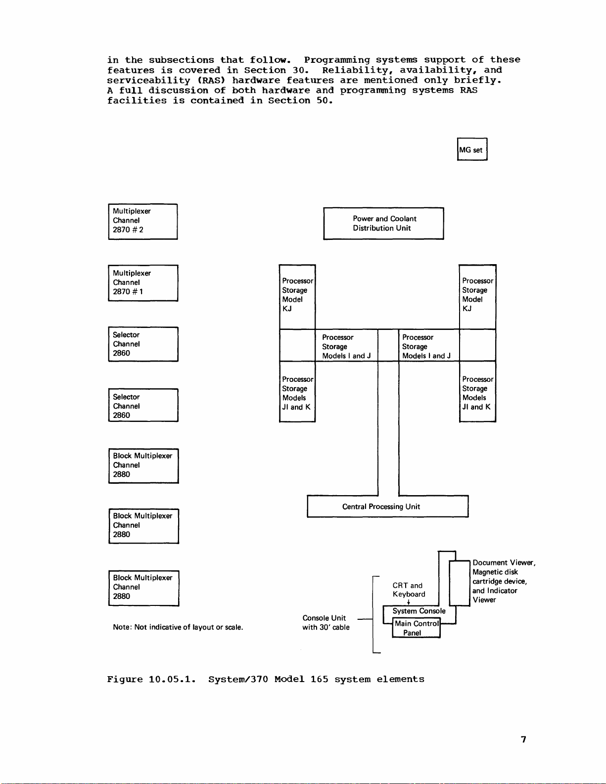
Figure
in
DOS
MCRR
execute
being
512
bytes
the
Model
relocation
165
these
among
elements
10.05.1.
programs
using
the
machine-dependent
machine-dependent
error-logging
correctly.)
that
that
use
depend
smaller
by
moving
deliberately
that
depend
165,
implemented
that
use
that
are
on
System/360
are
the
System/360
of
Each
routines
the
ASCII
on
than
the
the
1512
mode
nonusable
bytes.
CPU
written
on
devices
for
example,
in
model-dependent
not
necessarily
models
same
types
models.
the
Model
component
165
and
data
logout
bit
logout
to
cause
or
the
the
Model
operations
of
restrictions
computing
its
such
area.
for
System/360
in
the
lower
This
area
area.
certain
architecture
native
file
67,
compatible
system
new
features
as
that
(OS SER
PSW
processor
can
(See
program
not
of
etc.
of
the
with
that
which
and
models
storage
be
reduced
Section
implemented
the
Model
System/370
the
exist
are
illustrated
are
discussed
is
MCH
will
50.)
checks
same
for
6
Page 14
in
the
subsections
features
is
serviceability
A
full
discussion
facilities
covered
is
contained
(RAS)
of
that
in
hardware
both
follow.
Section
hardware
in
Section
Programming
30.
Reliability,
features
and
50.
systems
are
mentioned
programming
support
availability,
only
systems
of
briefly.
RAS
these
and
Multiplexer
Channel
2870
#2
Multiplexer
Channel
2870
# 1
Selector
Channel
2860
Selector
Channel
2860
Block Multiplexer
Channel
2880
Processor
Storage
Model
KJ
Processor
Storage
Models
JI and K
Power and Coolant
Distribution
Processor Processor
Storage Storage
Models I and J Models I and J
Unit
Processor
Storage
Model
KJ
Processor
Storage
Models
JI and K
Block Multiplexer
Channel
2880
Block
Multiplexer
Channel
2880
Note:
Not
indicative
Figure
10.05.1.
of
layout
or
scale.
System/370
Model
~
Console
with
30'
165
Central Processing
Unit
cable
system
Unit
CRT and
Keyboard
t
elements
I
Document Viewer,
Magnetic disk
cartridge device,
and Indicator
Viewer
7
Page 15
10:10
THE
CENTRAL
PROCESSING UNIT (CPU)
AND
THE
SYSTEM
CONSOLE
CENTRAL
The
the
PROCESSING UNIT
CPU
instructions
optionally,
one
of
the
The
CPU
path.
the
Extensive
validity
arithmetic
failing
as
an
CPU
availability
Among
execution
Instruction
The
faster
to
the
use
in
the
Model
an
execution
with
instruction
controlled
concurrently
The
instruction
sequence),
instruction
branches.
immediately
are
prefetched
instruction
insures
is
the
taken
contains
those
three
has
of
operations
operations,
the
major
unit,
and
of
65.
unit
by
while
decodes
operands,
When a
following
unit.
availability
or
not.
in
in
7000-series
an
80-nanosecond
parity
the
feature
elements
local
Execution
internal
more
concurrence
The
that
execution.
logic
the
unit
instructions,
conditional
and
placed
TWo
all
the
the
System/370
the
hardware
checking
data
being
are
without
storage,
performance
Model
overlap
circuits
execution
prefetches
and
the
16-byte
of
elements
emulator
used.
checked.
and
is
in
the
and
Units
in
165
instruction
The
and
makes
branch
branch
in
separate
instruction
prefetched
necessary
Model
compatibility
programs.
cycle
is
time
performed
All
Automatic
programming
discussed
CPU
are
control
of
the
CPU
operations
CPU
contains
Model
can
unit
165
process
is
instructions
calculates
estimates
is
encountered,
and
those
instruction
instructions
to
165
instruction
and
an
in
data
hardware
assistance,
in
the
instruction
storage.
Model
an
fetching
instruction
several
executing
addresses,
of
the
located
buffers
decode
feature
8-byte-wide
the
CPU
transfer,
the
RAS
165
is
than
is
instruction
and
instructions
a
single
(maintaining
success
the
at
the
buffers
are
whether
and
execute
set
and,
required
to
insure
logical,
retry
is
of
provided
section.
unit,
due
in
implemented
unit
preparation
unit
is
instruction.
them
prefetches
of
conditional
instructions
branch
within
used.
the
by
data
and
most
the
part
and
in
address
the
This
branch
The
execution
instruction
instruction
and
floating-point
is
used
to
bit
serial
An
imprecise
is
made
protected
Local
Local
registers
can
Storage
be
to
location.
storage
and
accessed
simultaneously.
Model
(ROS)
have
microcode
microcode
165
and a monolithic
an
80-nanosecond
for
necessary
instructions
8
unit
at a time.
every
cycle.
perform
adder
is
interrupt
store
and
data
Control
contains
has a read
by
control
a
specific
and
some
is
microprogram
It
arithmetic
binary
used
at
in
an
or
four
sources
storage
writable
cycle
system
to
execute
specialized
has
the
Emphasis
operations.
and
floating-point
the
execution
occurs
invalid
Storage
the
general
write
and
consists
control
time.
configuration.
the
controlled
capability
is
placed
on a Model
storage
purpose
cycle
time
written
of a capacitor
storage
ROS
and
majority
routines.
of
on
A
64-bit
arithmetic,
of
packed
165
address
and
of
into
WCS
of
WCS
and
can
processing
optimizing
parallel
decimal
only
if
or
floating-point
80
nanoseconds.
from
read-only
eWCS),
contain
ROS
contains
the
Model
contains
execute
a
new
fixed
adder
while
arithmetic.
an
attempt
at a storage-
one
source
both
of
all
required
the
165
the
one
binary
an
8-
It
storage
which
Page 16
microprogramming
set
for
the
Model
series
writable
nonresident
diagnostics
compatibility
WCS
is
control
also
diagnostics
can
storage.
required
165
used
storage
be
provided
and
feature.
to
house
in
to
to
handle
other
the
overlay
without
the
optional
diagnostic
Model
each
the
balance
features,
routines.
165
other.
necessity
in
of
addition
Thus
the
such
of
instruction
The
to
more
adding
as a 1000-
use
of
some
ROS
allows
extensive
more
control
During
microcode
device
in
installation
the
optional
Program
The
in
the
States
program
current
indicators,
control
registers,
implemented
CPU
is
in
the
new
LOAD
processor
status
to
indicators
support
The
contents,
System/310
with
one
mode
in
System/360
165.
Model
for
would
the
in
50).
manner
(It
165,
Systern/360
become
The
implementation
Model
Models
However,
on
a
power-on
sequence,
from a removable
the
console
will
be
tailored
features
and
System
states
program
called
control
0-15,
in
the
Model
the
supervisor
CONTROL
storage
instruction,
with
contained
new
system
layout,
models
exception.
are
Bit
models,
must
be
set
nor
was
the
models,
the
ASCII
165
has
been
65
and
15
in
the
other
the
Model
165
magnetic
unit.
included
Interrupts
in
which
status
registers,
can
165.
state.
the
STORE
in
functions.
and
identical
12
in
is
to
zero.)
mode
bit
since
standard
of
the
altered
order
four
as
on
WCS
The
magnetic
to
include
in
the
the
word
be
addressed;
They
A
and
CONTROL
control
function
to
the
not
used
ASCII
supported
the
expectation
has
machine
considerably
to
enhance
interrupt
Models
is
automatically
disk
system
Model
(PSW)
located
are
program
control
its
registers
of
these
PSW,
which
for
mode
not
been
check
system
levels
65
and
cartridge
disk
the
cartridges
microcode
configuration.
165
is
operating
and
in
new
in
however,
addressable
register
contents
instruction.
fixed
locations
locations
sets
this
by
is
IBM
purpose
not
that
borne
level
from
availability
operate
15.
loaded
contained
required
CPU
status
the
CPU. Up
only
can
can
4
be
be
Additional
are
required
0-121
in
Systern/360
EBCDIC
in
implemented
programming
System/360
out.
of
interruption
its
implementation
in
with
on
sent
are
are
when
set
placed
or
ASCII
the
systems
ASCII-8
(see
the
system
a
to
an
by
reflected
to
16
the
with
in
in
order
in
models
Model
in
the
in
Section
same
CPU
Features
Significant
Expanded
The
standard
superset
of
the
System/360
System/310
165
standard
instructions
precision
and
time
CPU
ID
instruction
it
is
operating
CHANNEL
present
features
Instruction
of
that
architecture
instruction
and
floating-point
of
day
ID
instruction
in
the
system.
Set
instruction
provided
instruction
all
binary,
clock
instructions
permits
and
provides
of
the
for
and
set
arithmetic
a
can
be
Other
Model
set
for
System/360
set
provide
includes
decimal,
program
the
system
used
new
165
the
plus
new
additional
all
floating-point,
instructions.
are
also
to
to
identify
standard
CPU
are
Systern/310
Models
instructions
functions.
general
standard.
determine
serial
number.
the
instructions
the
Model
65
and
purpose
Storage
the
types
following:
165
15.
that
The
and
and
extended
protect
The
new
model
The
of
are:
is
a
It
consists
support
Model
I/O
STORE
upon
which
new
STORE
channels
9
Page 17
•
Extended
Precision
Floating
Point
Precision
34
decimal
format.
(16
bytes)
instead
representation.
digits,
Seven
preciSion
multiplication
pair
long
•
General
Six
of
to
general
control
the
Model
SHIFT
or
left
save
time
6
for
commercial
MOVE
one
LONG
location
thereby
This
instruction
instructions
and
operation
and
deblocking,
frequently
of
up
digits,
Extended
to
represent
of
using
of
precision
floating-point
feature.
operations
floating-point
short
form
Purpose
purpose
and
processing
165
standard
AND
ROUND
shifting
to
18
bytes
each
decimal
processing.
provides
in
removing
or
of
performed
to
28
hexadecimal
is
provided
precision
one
doubleword
Fourteen
is
instructions
They
registers,
or
from
Instructions
instructions,
program
instruction
DECIMAL,
of
packed
of
instruction
shift
for
the
storage
the
current
can
eliminate
the
inclusion
MOVE
field
LONG
padding,
in
by
is
achieved
an
extended
hexadecimal
provided
provide
for
extended
extended
performance,
using
a
decimal
and
movement
to
another
limitation
the
of
facilitates
and
commercial
digits,
the
precision
as
is
by
the
are
addition,
and
to
which
set.
single
data.
storage
round
of
with
necessity
move
storage
processing.
approximately
extended
by
using
done
in
digits,
long
floating-point
included
subtraction,
precision
the
ability
long
will
form.
be
have
instruction,
This
and
operation
up
to
16
a
single
of
256
of
subroutines.
efficient
clearing,
precision
two
doublewords
floating-point
long
form
or
up
to
in
the
extended
data,
to
round
of
benefit
been
added
provides
instruction
instruction
performed
million
instruction,
bytes
per
multiple
The
record
operations
equal
data
17
decimal
and
using
from
to
can
execution
in
bytes
move.
move
format
blocking
to
number
format.
a
both
to
right
from
COMPARE
of
up
256-byte
compare
identified.
The
interruptable.
execution,
up
awaiting
COMPARE
instructions
registers
boundary
register~
can
writers,
addresses.
High-Speed
This
fixed-
a
long
to
.78
and
precision
.61
microseconds.
to
.42
LOGICAL
to
16
million
limit
occurs,
MOVE
LONG
and
the
termination
LOGICAL, STORE,
provide
and
permit
to
be
and
stored
be
of
most
and
to
Multiply
feature
substantially
floating-point
floating-point
microseconds.
LONG
can
bytes
on
byte
the
two
COMPARE
Thus,
interrupt
byte
nonword-size
compared
from a register.
benefit
others
Feature
A
fixed-point
be
in
compares.
characters
LOGICAL
when
an
can
of
what
and
addressability
to
data
to
control
who
must
(Optional)
increases
multiply
used
to
length,
I/O
be
taken,
might
INSERT
in a register,
manipulate
operations.
multiply
mUltiply
compare
thus
In
addition,
that
LONG
removing
caused
instructions
operation
and
be a lengthy
CHARACTERS
within
data
that
These
program
the
programmers,
internal
operation
operation
logically
when
the
terminates
the
channel
UNDER
the
is
not
loaded
three
processor
performance
With
use
improves
two
fields
the
current
an
unequal
inequality
are
during
is
not
move
or
MASK
general
on a word
into
instructions
to
compiler
storage
of
this
from
improves
are
their
held
compare.
purpose
a
of
feature
1.81
from
10
Page 18

Page
of
Revised
By
TNL
GC20-1730-0
7/14/70
GN20-2227
Architecture
Two
alterations
165
during
System/310
that
check
the
and
the
operations.
the
instruction
during
than
that
program
that
blank
deletion
protection
MARK
execution
termination,
the
check
has
For
example,
field,
The
second
instruction.
data
the
or
exception
when a pattern
storing
eliminates
165.
described
Interval
but
The
Timer
unpredictable
occurrence
is
Implementation
have
execution
System/360
validity
On
the
Model
to
be
suppressed
as
is
done
of
an
fields
occurs,
invalid
when
the
program
involved
sign.
an
sign
termination
a
can
alteration
during
On a
character
remains
unchanged
of a protection
model-dependent
(Standard)
Alterations
been
of
made
certain
models.
of
operands
165.
on
instruction
remain
routine
invalid
be
corrected
concerns
the
Model
is
165 a protection
fetched
during
system
for
to
the
instructions
The
involved
an
invalid
(never
System/360
when
unchanged.
can
be
sign
is
the
results
avoided.
recognition
execution
from a location
the
operation
exception
System/360
system
first
involves
in
sign
executed)
models.
an
invalid
executed
from
by
programming.
of
an
edit
during
models.
action
common
packed
in
an
rather
Suppression,
sign
Therefore,
that
packing
of a storage
EDIT
exception
protected
operation.
editing
for
the
taken
to
all
decimal
operand
than
occurs
inspects
an
and
or
an
always
This
on a Model
situation
on a Model
both
instructions
causes
terminated
rather
insures
when
a
the
entirely
transaction
EDIT
AND
occurs
for
change
field
The
interval
of a Model
resolution
on
the
Model
higher
problems
resolution
encountered
execution
Time
of
This
Day
new
approximately
instructions
and
to
request
word
system
and
in
supervisor
The
the
interval
normal
interval
nance
its
tem
activity.
of
processor
console
time
operations
timer
because
updating
striction.
processing
165
has a resolution
(with
65.
durations
Clock
clock
142
(SET
that
state
panel
of
day
timer.
cannot
it
The
The
time
and
real-time
timer
in
60-cycle
Its
maximum
of
this
in
that
(Standard)
is a binary
years.
CLOCK
the
storage.
and
is
clock
Accurate
the
clock
be
is
not
may
be
lS.S-hour
of
decimal
power)
interval
accounting
are
less
It
is
and
STORE CLOCK)
current
The
only
in
can
when
the
be
time
stops
as
accurate
updated
omitted
cycle
day
clock
applications.
location
of
3.33
implemented
time
period
timer
routine
than
counter
updated
time
time
the
enable
used
of
only
when
under
time
better
the
of
be
can
clock
set
for
day
when
as
the
certain
of
80
ms
instead
remains
will
accuracy
16.6
52
bits
every
are
provided
stored
be
set
security
position.
more
can
be
CPU
the
clock
system
the
answers
in
fixed
of
for
the
standard
15.5
eliminate
caused
ms
resolution.
with a cycle
microsecond.
in a specified
only
when
switch
accurate
maintained
power
for
is
in
conditions
interval
the
timing
processor
the
16.6
hours.
many
by
to
set
the
time
because
is
turned
time
of
the
stopped
of
timer
needs
storage
ms
timer
The
of
the
task
of
Two
new
the
time
doubleCPU
on
the
stamping
off.
day
excessive
is
also
of
is
than
during
The
maintestate,
sys-
a
tele-
re-
£PU
Cooling
The
its
associated
water
is
required
packed
heat
generated
circulation
because
circuits
power
system.
in
frames
of
the
by
the
CPU.
the
Use
amount
logic
is
boards
removed
of
a
of
by
liquid
heat
in
the
forced
coolant
generated
Model
air
165
and a closed-loop
in
addition
by
the
CPU
and
to
densely
air
11
Page 19
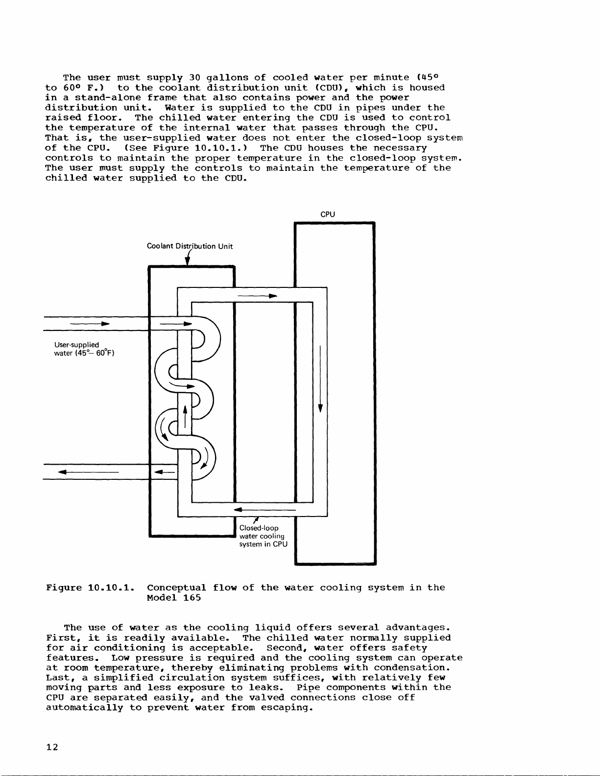
The
to
user
600 F.>
must
to
in a stand-alone
distribution
raised
the
That
of
controls
The
chilled
floor.
temperature
is,
the
the
cpu.
to
user
must
water
maintain
supply
the
coolant
frame
unit.
The
of
Water
chilled
the
user-supplied
(See
Figure
the
supply
the
supplied
30
gallons
distribution
that
is
water
internal
water
10.10.1.>
proper
controls
to
the
also
supplied
water
temperature
CDU.
of
cooled
contains
to
entering
that
does
not
The
to
maintain
unit
power
the
the
enter
CDU
water
(CDU>,
CDU
CDU
passes
houses
in
the
CPU
per
which
and
the
in
pipes
is
through
the
closed-loop
the
the
closed-loop
temperature
minute
power
used
necessary
is
housed
under
to
control
the
0
(45
the
cpu.
system
system.
of
the
User-supplied
(45°-
water
60°F)
Coolant Distribution
Unit
Figure
First,
for
The
air
10.10.1.
use
it
conditioning
features.
at
room
Last,
moving
cpu
temperature,
a
simplified
parts
are
separated
automatically
12
of
is
Low
water
readily
pressure
and
to
Conceptual
Model
as
165
the
available.
is
acceptable.
is
thereby
circulation
less
exposure
easily,
prevent
flow
cooling
required
and
water
of
the
liquid
The
and
eliminating
system
to
leaks.
the
valved
from
escaping.
water
chilled
Second,
the
problems
suffices,
connections
offers
water
water
cooling
Pipe
cooling
several
normally
offers
system
with
with
components
system
advantages.
supplied
safety
can
condensation.
relatively
within
close
off
in
operate
the
few
the
Page 20
Physical
arrangements
Installation
details,.
)
planning
are
made
Information,
for
to
Model
provide
Physical
165
the
installation
required
Planning,
should
water.
GA22-6971
insure
(See
for
that
System/370
more
Motor
the
from
Hz
Generator
The
motor
power
the
power,
building
Unlike
enough
set
unit
to
(including
approximately
Installation
MG
set
size
The
MG
with
IBM
ordering
3066
delivery
does
SYSTEM
A
stand-alone
not
the
approximately
165.
lights,
advanced
This
etc.,
console
indicator
configuration
loading
included
more
microcode
to
rapidly
Set
generator
required
and
supplies
the
MG
be
housed
the
Information,.
and
installation
set
should
up
manufacture
required
CONSOLE
25
unit
contains
required
viewer,
plugboard.
enable
than
by
the
electrical
sets
provided
within
required
six
be
to
two
MG
system
feet
away
features:
a
microfiche
and
diagnostics.
the
would
(MG)
set
Model
distribution
it
to
the
the
starter)
feet
long,
Physical
requirements.)
ordered
months
MG
sets.
set
through
console
from
the
system
for
system
a
cathode
a
system
customer
otherwise
is
the
165
CPU.
cPU.
for
the
covers
for
weighing
Planning
at
the
prior
to
a
procedure
IBM.
unit,.
the
CPU.
control
operation),
ray
document
activity
Certain
engineer
be
possible.
converter
It
takes
system,
7000-series,
of
the
system
the
Model
3000
for
same
time
system
which
is
can
required
panel
tube
viewer,
monitor,
of
to
detect
unit
60
converts
which
itself,
165
lbs.
more
as
details
the
installation.
is
established
be
located
for
(buttons,
as
well
and
keyboard,
a
processor
and a device
these
features
CPU
that
provides
Hz
(cycle)
it
were
the
to
small
MG
power
415
is a stand-alone
(See
system/370
concerning
Model
165,
While
for
up
to
the
Model
switches,
as
standard
a
microfiche
storage
for
are
malfunctions
Installation
feature
panel
Display
The
In
normal
used
message
on a Model
section
Unit
cathode
as
the
display
operator
whether
is
used.
to
display
and
address
keys,
The
for
a
-framing-
switch-
to
a
floating-point
array.
each
microfiche
display
to
240
indicators"
incandescent
labels
may
the
be
displayed,
of
Model
mode,
operating
warning
visual
In
CE
and
of
which
of
concept:
select
lights
lights.
of
the
165
the
system
1.
ray
tube
the
CRT
required
indicators
indicator
mode.
manually
registers,
Data
is
represents
indicator
status
anyone
the
along
In
yet
optional
permits
(CRT)
and
system
by
the
CRT
alter
entered
and
control
the
customer
of
current
with
this
the
console
Remote
duplication
console
unit
alphameric
operator's
large
are
provided.
or
an
audible
and a set
processor
the
in
a
hexadecimal
viewer
ten
images.
value
the
way
up
Operator
unit
on a 2150
provided
keyboard
console
systems
alarm
of
storage,
channel
hexadecimal
is
included
indications.
engineer
of
which
appropriate
to
2400
requires
of
the
contains
like
A
switch
the
with
16
data
buffers,
by
digit.
in
uses
Each
image
is
microfiche
status
only
Console
operator
Console
a
are
designed
to
provide
Model
setting
volume
keys
the
general
or
means
the
The
display
a
-frame
consists
then
and
240
incandescent
Panel
control
or a 2250
4K
buffer.
the
165.
determines
control
can
be
the
CPU
of
the
console
utilizes
selection
displayed
image
control
Attachment
to
be
rapid
Two
used
purpose
buffer
data
unit
of
up
in
that
triggers
lights.
13
Page 21
A
microfiche
display
more
in
microfiche
The
of
than
processor
generation
available
etc.)
when
configuration
information.)
at
any
the
The
given
indicator
system
on
activity
located
to
be
be
displayed"
1.
in
displayed
Percentage
a.
b.
c.
2.
Percentage
channels
activity
customer
half
of
to
power
of
the
the
Total
Time
Time
document
of
all
form.
storage
the
required
the
operating
is
W
push-button.
The
exact
time
can
viewer.
activity
CPU
main
is
selected
one
measurement
of
time
CPU
CPU
of
are
overlap)
viewer
engineer
Model
165
configuration
processor
system,
brought
up
processor
be
verified
monitor
and
the
channels
control
panel
via
compute
CPU
is
is
active
is
active
time
the
concurrently
is
reference
CE
reference
their
or
upon
(See
Section
by
is
capable
in
a
set
at
a
time
relative
active
in
supervisor
in
problem
CPU
and
active
included
materials.
plugboard
storage
depression
storage
displaying
via
the
of
time.
one
(to
in
the
materials
configuration
addressing,
10:15
for
configuration
the
of
displaying
the
system
system
console.
switches.
to
the:
state
state
or
more
determine
console
It
permits
interleaving,
of
an
further
appropriate
activity
The
of
the
is
expected
will
automatic
Wenter
in
the
The
following
selected
CPU
and
unit
be
(units
effect
average
meter
activity
channel
for
that
supplied
image
can
3.
Percentage
of
concurrently
4.
Percentage
more
of
of
the
activity)
5.
Percentage
are
processor
A
device
system
the
diagnostics
indicator
interchangeable
device
customer
10:15
buffer
this
The
is
engineer
STORAGE
Model
storage
time,
used
busy
that
165
such a concept
of
accessing
storage
provides
viewer
magnetic
for
who
has a two-level
backed
high-internal-performance
195.
storage
high-speed
The
Model
with
monolithic
165
a
two-microsecond
time
(to
determine
time
selected
time
is
contained
and
WCS
loading.
will
by
has
four-way
buffer
when
all
channel
when a single
channels
any
of
the
the
selected
read-only
in
the
document
disk
cartridges.
It
load
diagnostics
memory
a
large
was
processor
implemented
systems,
doubleword
cycle
storage
of
the
are
selected
storage
the
viewer.
is
such
time,
with
selected
activity
selected
busy
storage
system
As
also
system
(main)
only
as
System/360
buffered
an
channels
overlap)
channel
(to
determine
channels
protect
for
WCS
microcode
console
This
device
already
a
debugging
from
- a
it.
very
storage.
in
very
interleaved
by
80-nanosecond
are
or
one
channel
and
the
key
area
unit
between
reads
indicated,
tool
high-speed
Prior
large-scale,
Models
processor
8K
or
cycle
CPU
and
for
85
16K
busy
or
of
this
the
to
and
of
time.
The
reduces
contributes
165
is
14
use
of
interleaving
the
effective
to
the
approximately
fact
storage
that
two
and a two-level
cycle
the
internal
to
five
times
of
memory
the
Model
performance
that
of
the
system
165
Model
and
of
drastically
greatly
the
Model
65.
Page 22
PROCESSOR (MAIN)
STORAGE
Processor
Model
In
order
storage
storage
that
memory
can
present
boxes.
operate
in
the
box.
Depending
present
is 4 in
Models K and
10.15.1.
logical
can
be
(Model
memories
active
illustrated
addressed
doublewords
consecutive
each
That
location
is
through
of
four
is,
processor
8
is
in
logical
24
in
logical
all
storage
I
J
JI
K
KJ
to
achieve
in
A
logical
independently
Model
on
the
two
JI,
or
JI,
in
at
one
in
Figure
bytes
can
logical
memory
is
in
logical
memory
available
is
available
interleaving
the
system
165
is
storage
boxes
12
in
not
two
boxes.)
time,
10.15.1,
are
be
memories,
storage
1,
0(,
and
storage
CaEacity
512K
1024K
1536K
204SK
3072K
is
memory
12SK
size,
for
Models I and
six
boxes
shown,
thus
for
spread
accessed
requested
location
location
memory
the
locations.
in
the
in
divided
is
defined
from
all
or
256K
the
for
consists
However,
achieving
a 512K
across
concurrently
0
16
3.
Processor
address
following
the
Model
into
as
other
and
there
total
number
J,
Model
of
four
only
four-way
system,
logical
one
is
in
logical
is
in
logical
distribution
increments:
165,
logical
that
storage.
S
in
KJ,
12SK
four
portion
are
of
four
as
logical
the
memories
A
two
logical
boxes
shown
and
interleaving.
four
consecutively
memories
(one
doubleword
SO-nanosecond
memory
memory
storage
location
sequence
processor
of
logical
per
storage
memories
for
in
Figure
four
memories
so
that
cycle
0,
location
2,
and
continues
within
storage
256K
As
32
from
apart).
32
15
Page 23
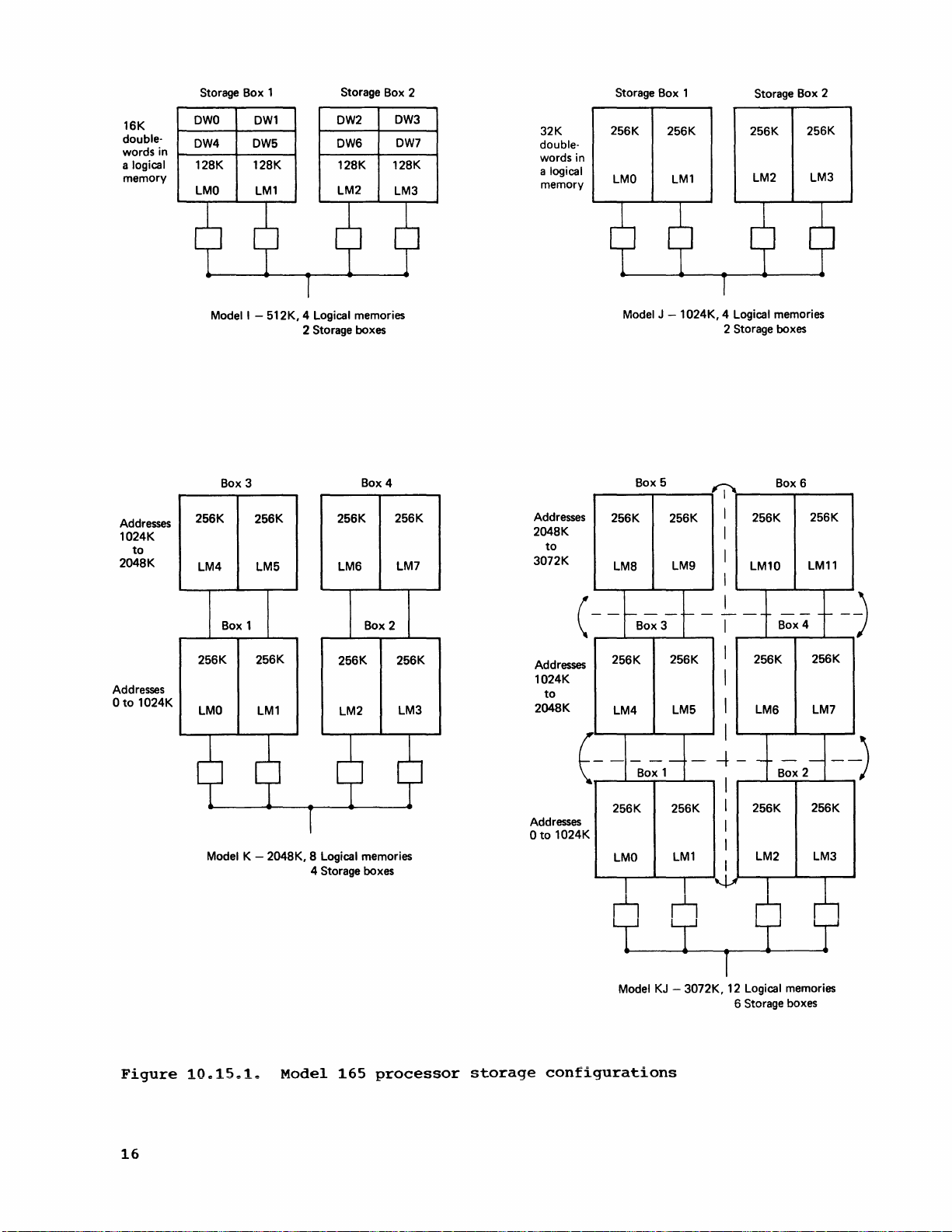
16K
doublewords in
a
logical
memory
Storage Box 1
OWO
OW4
128K 128K 128K 128K
LMO
OWl
OW5
LM1
Storage Box 2
OW2
OW6
LM2
OW3
OW7
LM3
32K
doublewords in
logical
a
memory
Storage Box 1
256K
LMO
256K 256K
LMl
Storage Box 2
256K
LM2
LM3
Addresses
1024K
to
2048K
Addresses
o
to
1024K
Model I - 512K, 4 Logical memories
Box 3
256K
LM4
256K
LMO
256K
LM5
Box 1 Box 2
256K
Model K - 2048K, 8 Logical memories
LM1
2 Storage boxes
Box 4
256K 256K
LM6
256K
LM2
4 Storage boxes
LM7
256K
LM3
Addresses
2048K
to
3072K
Addresses
1024K
to
2048K
Addresses
o
to
1024K
Model J - 1
256K 256K
LM8
--
(
256K
LM4
--
E
256K 256K
LMO
n n
Box 5
LM9
~--
Box 3
256K
LM5
-
--
Box 1
LMl
I I
024K, 4 Logical memories
2 Storage boxes
256K
Box 6
256K
I
I
I
I
LM10
LM11
I
I
f-
-
---
I
I
256K
--
Box 4
I
I
LM6 LM7
I
256K
LM2
I
- -
Box 2
256K
-
~--
I
I
I
I
I
~
f--
-
256K
-
LM3
I
n
-)
Figure
16
lOe15.1.
Model
165
processor
storage
L r
Model KJ - 3072K, 12 Logical memories
configurations
T
r
6 Storage boxes
Page 24
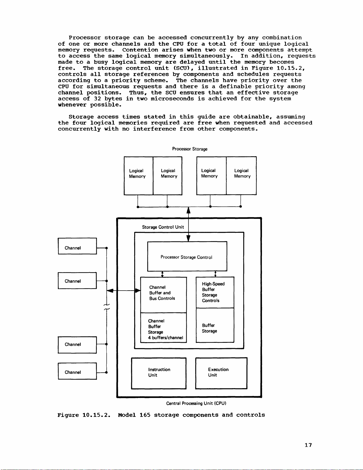
Processor
of
one
memory
to
access
made
controls
according
CPU
channel
access
whenever
to a busy
free.
for
storage
or
more
channels
requests.
the
same
logical
The
storage
all
storage
to a priority
simultaneous
positions.
of
32
bytes
possible.
can
be
and
Contention
logical
memory
control
references
scheme.
requests
Thus,
in
two
accessed
the
CPU
arises
memory
unit
the
microseconds
simultaneously.
are
delayed
(SCU),
by
components
The
and
there
SCU
ensures
concurrently
for a total
when
two
until
illustrated
channels
is a definable
that
is
achieved
or
and
have
by
of
more
In
the
schedules
priority
an
effective
for
any
combination
four
in
unique
components
addition,
memory
Figure
priority
the
logical
attempt
requests
becomes
10.15.2,
requests
over
storage
system
the
among
Storage
the
four
concurrently
Channel
I
Channel
I
access
logical
with
~
-
-
r'-'
,.
....
times
memories
no
interference
Logical
Memory
1
Storage Control
...
,
...
stated
required
in
Processor Storage
Logical
Memory
1 1 1
Unit
Processor Storage Control
: t
Channel
Buffer and
Bus
Controls
this
are
from
Jl
"
guide
free
other
Logical
Memory
High-Speed
Buffer
Storage
Controls
are
obtainable,
when
requested
components.
Logical
Memory
assuming
and
accessed
Channel
I
Channel
I
Figure
~
~
10.15.2.
Model
Channel
Buffer
Storage
4 buffers/channel
Instruction Execution
Unit
Central Processing
165
storage
components
Buffer
Storage
Unit
Unit
(CPU)
and
controls
17
Page 25

Error
detection
and
detection,
bit
errors.
The
Model
processor
allows
the
formats)
program
on
integral
interrupt.
multiples
not
apply
Use
of
performance.
commercial
records
field
and
alignment.
elimination
increases
in
which
rate,
binary
run
can
and
A
program
on a System/360
programs
without
byte
boundary
checking
and
correction
but
The
165
storage.
storage
to
appear
boundaries,
of
operand
to
alignment
byte
alignment
However,
processing
to
blocked
of
padding
effective
throughput
achieve
floating-point
written
that
are
orientation
rules.
and
correction
not
correction,
ECC
feature
also
supports
The
presence
operands
on
any
Without
that
l~ngths.
of
byte
to
records
The
smaller
bytes
I/O
data
is
in
performance
to
use
model
to
run
(ECC)
of
all
single-bit
of
is
discussed
a
byte
of
of
unprivileged
byte
boundary
this
is,
facility,
on
Byte
instructions
in a program
orientation
eliminate
to
the
insure
physical
requires
rates.
almost
direct
improvement
data.
byte
that
on
both
should
boundary
does
the
be
written
hardware
all
double-bit
fully
boundary
the
byte-oriented
without
storage
orientation
or
channel
degrades
can
padding
binary
record
less
I/O-bound
proportion
by
alignment
not
have
Model
165
provides
processor
in
alignment
instructions
causing
operands
addresses
is
instruction
be
used
bytes
and
that
external
commercial
using
the
feature.
and
to
adhere
automatic
storage
and
most
the
RAS
facility
operand
(RX
a
must
be
that
standard
command
effectively
added
floating-point
results
storage
to
the
byte
alignment
will
on
not
System/360
to
integral
errors
multiple-
section.
for
function
and
RS
specification
aligned
are
integral
and
does
words
(CCW's).
execution
in
within
from
the
and
programs,
I/O
data
for
necessarily
Therefore,
models
Processor
If
configured
plugboard
re-IPLed
storage.
during
The
the
operative
boxes
reduced
odd
number
in
systems
of
boxes
in a 3072K
Serial
Storage
a
processor
out
in
and
The
a
power-on
user
to
achieve
from
of
with
instead
operation
of
the
system
the
system
configuration
has
the
system
consecutive
four-way
boxes.
four
of
(six-box)
is
engineers.
The
configuration
inserts
processor
up
to
to
two
up
to
With
in
the
box
(Refer
sequential
plugs
storage
three
plugs,
plugs,
two
plugs.
the
few
first
configuration
to
Figure
positioning
into
and
or
reversal
last
10.15.1,
Boxes 1 and 2 would
and
4,
respectively,
Reconfiguration
storage
the
box
system
console.
can
continue
indicated
sequence
ability
and
to
or a system
to
reconfigure
two-way
Therefore,
or
six
processor
the
malfunctioning
system
as a 2560K
possible
panel
the
is
appropriate
configuration:
box
addressing
interleaving
combinations
box
addressing
is
to
be
configured
in
o~
consecutive
be
vertically
and
then
develops
by
use
remove
storage
if
four-way
also
relatively
(four-way,
which
with
a
of
the
Then
the
operating
by
reset
one
the
addressing.
the
storage
box
configuration
and
will
holes
number
sequence
defined,
position.
out
box
numbers
processor
reversed
boxes
malfunction,
storage
operating
with
the
plugboard
operation.
or
more
addressing
configuration
interleaving
boxes
only.
be
used
simple
in
of
the
boxes
(box
to
panel
reversals)
two-way,
any
Assume
of
the
also
storage
in
position
5
and
6,
it
configuration
system
reduced
is
storage
of
the
Interleaving
consists
can
by
removing
A
pair
is
not
primarily
use.
to
(one
to
or
serial)
box
can
box 2 in a six-
operational
indicate
box
with
respectively.
can
be
can
available
established
boxes
remaining
be
maintained
must
be
supported.
by
The
operator
describe
six)
using
using
be
placed
system.
the
addressing.)
boxes
be
from
is
of
an
a
pair
removed
customer
the
using
up
3
Box
18
Page 26
2
is
then
ripple
(discussed
malfunctioning
boxes
4,
6,
position.
4-3,
6-5,
in
and
(The
2-1.)
the
box,
2,
ascending
last
(or
below)
a
horizontal
respectively,
highest)
can
be
addressing
addressing
performed
reversal
puts
box 1 in
sequence
on
of
position
it.
boxes
the
of
the
If
box 1 is
3,
highest
boxes
and
an
5,
and 1 with
addressing
is
inline
the
then
Storage
as
nonprogrammed
storage
is
requires
an
executed
of
storage
ripple
system
there
uniprocessor
Ripples
Five
storage
maintenance
address
provided
dedication
inline
processor
on a malfunctioning
the
operational
box
is
not
unavailability
is
no
aids
read
for
must
provided
reconfiguration
Model
HIGH-SPEED BUFFER
The
increase
largely
8K
for
permits
bytes
can
(or
processor
pictured
buffer
CPU
The
from
be
18
by
the
is a standard
fetches.
inclusion
buffer
has
the
initiated
cycles)
storage.
in
Figure
inclusion
buffer
required
ripple
functions
for
or
write
for
the
ROS, wes,
of
the
storage
system
be
in
the
for
during
65
systems.
STORAGE
in
the
internal
Installation
of
an
an
80-nanosecond
in
every
cycle.
The
10.15.3.
are
use
by
customer
of
ones
purpose
local
system
ripple
of
locating
storage,
to
also
storage
while
highest
the
processing
addressing
Model
processor
capability
performance
of a high-speed
feature
additional
of
and
the
8K
cycle.
two
cycles,
This
to
obtain
conceptual
eight
data
implemented
engineers.
or
zeros
and
the
ripple
is
implemented.
box
that
continues.
65,
which
storage
for
main
buffer
provides
optional
of
buffer
The
or
160
compares
bytes
flow
in
Model
(A
through
a
malfunction.)
processor
function.
has
been
position.)
therefore
rippling.
storage
of
the
Model
storage
high-speed
Buffer
storage.
CPU
can
nanoseconds,
with
1.44
of
data
in
the
Model
165
ripple
every
available
storage
However,
It
configured
(The
An
requires
In
boxes
165
unit.
data
Expansion
obtain
and a request
microseconds
directly
165
hardware
is
a
A
ripple
that
can
be
out
processor
inline
total
addition,
in
is
achieved
The
access
feature
eight
from
is
Buffer
is
transparent
program
The
buffer
that
used
have
shown
buffer
storage
structure
algorithm
in
that
95~
of
control
to
the
in
the
System/360
in a Model
the
time
and
programmer,
order
to
implemented
Model
165
on
the
use
is
who
obtain
in
195.
the
data
average.
handled
need
close
the
entirely
not
to
Model
Sample
accessed
adhere
optimum
165
is
job
step
by
by
to
use
very
the
hardware
any
particular
of
the
similar
executions
CPU
is
buffer.
in
and
to
the
19
Page 27

Channel
Channel
V-
Processor Storage
Logical
Memory
CPU
Instruction
Unit
Execution
Unit
~\
8
Bytes
~
-
h
I I
8 Bytes
Buffer
Storage
8 Bytes
Box
Logical
Memory
-0-
..
"
-
J~
8
Bytes
fr
LQ-
Logical
Memory
Box
Logical
Memory
CPU
CPU
(18
Buffer
bytes
Channels
cycle
Figure
The
controls
the
channels,
of
the
and
stores.
buffer.
When a
determines
buffer
If
the
20
fetch
fetch
cycles)
fetch
(18
10.15.3.
storage
all
SCU
handles
data
whether
by
interrogating
data
requested
from
from
cycles)
to
and
control
buffer
and
Parity
fetch
buffer
processor
from
conceptual
assume
processor
from
and
manual
CPU
checking
request
or
not
is
no
unit
processor
to
its
-
160
storage
processor
data
interference.
(SCU)
controls.
processor
is
is
the
requested
address
present
nanoseconds
-
1.44
storage
storage
flow
used
made
in
in
contains
storage
The
storage
for
by
array
the
for
microseconds
-
1.44
-
the
the
references
buffer
references,
data
the
CPU,
data
of
the
buffer,
8
bytes
microseconds
32
bytes
high-speed
storage
verification
buffer
is
in
the
buffer's
it
is
(2
for
in
a 2
Times
made
control
both
storage
high-speed
sent
cycles)
8
bytes
for
microsecond
given
buffer
by
the
portion
fetches
in
the
contents.
directly
32
and
CPU,
control
Page 28
to
the
CPU
data
The
CPU,
storage
write
buffer
being
The
is
not
data
location
both
location
maintained
channels
from
procpssor
the
affected
buffer,
the
storage.
The
entire
switch
is
and
of
A
storage
disabled,
effective
The
128
block
or
8K
bytes
that
a maximum
per
column
buffer
valid
block
data.
without
currently
obtained
the
processor
storage,
data
via
buffer
is
32
of
times
All
is
and
buffer
being
in
never
processor
is
buffer
execution
all
CPU
system
is
each.
bytes
are
on a 32-byte
256
different
64
and
is
valid
a
processor
in
sent
stored
and
altered
the
buffer.
access
storage
the
address
storage
placed
can
of
fetches
execution
shown
Every
and
can
columns).
set
to
triggers
storage
the
buffer,
to
tQe
in
the
processor
is
the
only.
array
address
in
the
be
disabled
a DIAGNOSE
are
speed
in
Figure
buffer
contain
boundary.
blocks
A
indicate
are
a
CPU.
buffer.
storage
one
buffer
When a
is
buffer
manually
made
is
10.15.4.
column
32
of
processor
valid
whether
set
reference.
processor
The
data
When
are
whose
contents
directly.
channel
interrogated.
is
being
as
well
instruction.
directly
reduced.
is
subdivided
consecutive
The
8K
trigger
or
off
during
If
the
storage
is
also
data
updated
is
if
are
They
stores
If
maintained
as
in
processor
by a system
When
to
processor
It
contains
into
bytes
buffer
storage
is
not
can
data
associated
the
block
system
Page
Revised
By
requested
fetch
assigned
stored
the
currently
read
into
data
data
in
console
the
buffer
storage
64
columns
four
from
contain
(4
with
contains
reset
of
GC20-1730-0
7/14/70
TNL
GN20-2227
is
made.
a
by
the
processor
and
in
from
the
blocks.
processor
blocks
each
or
IPL.
Processor
columns
blocks
column
an
8K
buffer
determine
a
processor
1024K.
be
placed
Figures
buffer
The
storage
column.
columns
blocks
halved
storage
The
storage
system
storage
as
buffer
in a buffer
varies
with
is
which
storage
Any
of
the
in
any
10.15.5
storage
larger
blocks
If
is
addressing.
the
that
a
16K
doubled
contending
if
processor
divided
16K
buffer
configurations
throughput
storage:
column,
the
present,
of
the
column
512
of
the
and
10.15.6
processor
contend
buffer
from
for
storage
into
is
results
is
logically
size
bits
64
columns
blocks
four
is
64
the
blocks
128
columns
provided
that
from
64
or
the
number
of
processor
21-26
consists
in a given
blocks
show
storage
for
the
used
to
128;
size
for
have
an
divided
128.
While
of
of
the
to
use.
of
512
in
the
the
formats
size,
four
instead
the
number
in
each
remains
has
256
users
with
applications
increase
into
th~
there
blocks
in a processor
storage.
processor
As
shown
blocks
processor
corresponding
used
the
greater
blocks
of
an
in
8K,
of
buffer
the
blocks
column
same.
per
larger
such
in
internal
same
For
are
number
always
example,
storage
in
Figure
in a system
storage
for
processor
the
the
same
the
number
processor
is
(A
1024K
column.)
Model
that
increased
performance.
column
buffer
number
buffer
storage
thereby
165
of
four
storage
when
address
10.15.4,
with
can
column.
and
of
of
buffer
processor
processor
21
Page 29
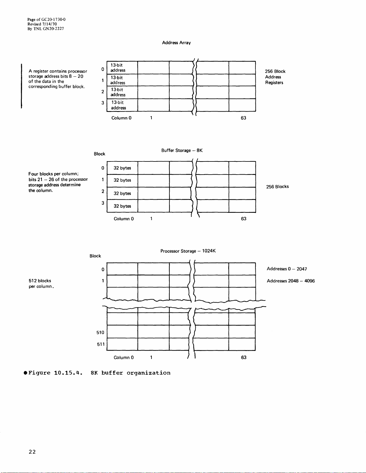
Page
of
GC20-1 730-0
Revised
7/14/70
By
TNL GN20-2227
Address Array
A register contains processor
storage address bits 8 of
the
data
in
corresponding
Four
bits
21 -26
storage address
the
column.
the
buffer
blocks per column;
of
block.
the
processor
determine
20
o
Block
2
3
o
2
3
13-bit
address
13-bit
address
13-bit
address
13-bit
address
Column 0
32
bytes
32
bytes
32
bytes
32
bytes
Column 0
Buffer Storage -
J J
)
)
\
)
~
J
I
,
8K
J
J
)
\
63
63
256
Block
Address
Registers
256
Blocks
512
blocks
per
column.
.Figure
10.15.4.
Block
51
511
8K
Processor Storage -
0
1
............
to--
-
0
1
1.-
--...&....----'--""""""41
Column 0
buffer
-
-
-
-
organization
.\
} \
1024K
I
,
)
)
i
"'
7
---
---
-----
~
,
J
I
\\-----'-----1
63
Addresses 0 - 2047
Addresses
~
2048 -4096
22
Page 30
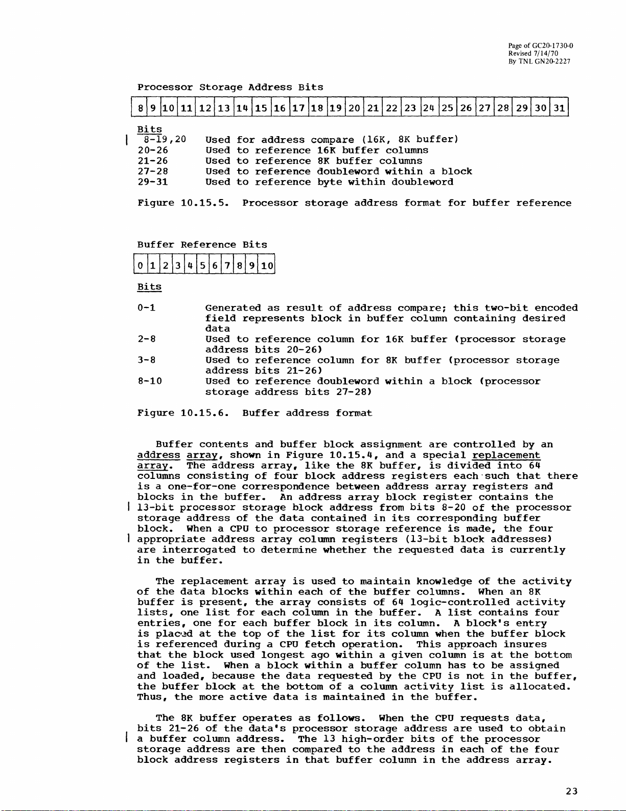
Page
of
Ge2D-17
Revised
7/14/70
By
TNL GN2D-2227
30-0
Processor
Bits
8-19,20
20-26
21-26
27-28
29-31
Figure
Buffer
Bits
0-1
2-S
3-8
8-10
Storage
Used
Used
Used
Used
Used
10.15.5.
Reference
Generated
field
data
Used
address
Used
address
Used
storage
Address
for
address
to
reference
to
reference
to
reference
to
reference
Processor
Bits
as
represents
to
reference
bits
to
reference
bits
to
reference
address
Bits
storage
result
20-26)
21-26)
bits
compare
16K
buffer
SK
buffer
doubleword
byte
block
of
within
address
in
column
column
doubleword
27-2S)
(16K,
columns
address
buffer
for
for
8K
buffer)
columns
within
doubleword
format
compare;
column
16K
buffer
SK
buffer
within
a
block
for
(processor
a
block
buffer
this
two-bit
containing
(processor
(processor
reference
encoded
desired
storage
storage
Figure
address
array.
columns
Buffer
10.15.6.
contents
array,
The
address
conSisting
is a one-for-one
blocks
13-bit
storage
block.
appropriate
are
in
of
buffer
lists,
entries,
is
is
that
of
and
the
Thus,
in
the
processor
address
When a
interrogated
the
buffer.
The
replacement
the
data
is
present,
one
one
plac'~d
at
referenced
the
block
the
list.
loaded,
buffer
the
more
address
blocks
list
because
block
Buffer
and
shown
of
correspondence
buffer.
storage
of
the
CPU
to
to
array
within
the
for
for
each
the
top
during
used
When a
at
active
address
buffer
in
Figure
array,
four
An
address
block
data
processor
array
column
determine
is
each
array
each
column
buffer
of
the
a
CPU
longest
block
the
data
the
bottom
data
format
block
10.15.4,
like
the
block
between
address
contained
storage
whether
used
of
consists
in
block
list
fetch
ago
within
within
requested
of a column
is
maintained
assignment
SK
buffer,
address
array
from
in
registers
the
to
maintain
the
buffer
of
the
buffer.
in
its
for
its
operation.
a
a
buffer
by
are
and a special
is
divided
registers
address
block
its
reference
array
register
bits
8-20
corresponding
is
(13-bit
requested
knowledge
columns.
64
logic-controlled
A
list
column.
column
given
column
the
This
column
CPU
when
approach
has
is
activity
in
the
buffer.
controlled
replacement
each"such
registers
contains
of
the
made,
block
data
addresses)
is
of
When
contains
A
block's
the
buffer
is
at
to
be
not
in
list
is
by
into
that
processor
buffer
the
currently
the
activity
an
activity
entry
insures
the
assigned
the
allocated.
an
64
there
and
the
four
8K
four
block
bottom
buffer,
The
bits
a
buffer
storage
block
SK
21-26
address
address
buffer
of
column
operates
the
data's
address.
are
registers
then
as
follows.
processor
The
compared
in
that
13
high-order
to
buffer
When
storage
the
column
the
address
bits
address
in
CPU
of
in
the
requests
are
used
the
each
address
data,
to
processor
of
the
array.
obtain
four
23
Page 31

Page
of
GC20-1730-0
Revised
7/14/70
By
TNL
GN20-2227
If
an
equal
the
address
buffer,
the
CPU
address.
buffer
block
replacement
If
the
the
requested
the
CPU,
the
column
of
the
activity
processor
are
made
assigned
on
and
the
in
the
appropriate
doubleword
data
buffer
required
so
compare
array
the
appropriate
as
determined
A
processor
array.
desired
and
involved
storage.
to
obtain
buffer
13
fetched
that
and
is
put
data
data
stored
list
block.
high-order
by
the
processing
occurs
the
by
storage
at
the
block
must
in
the
is
inspected
is
Four
the
32
column
from
CPU.
for
an
valid
doubleword
bits
27
reference
top
of
is
be
fetched
buffer.
assigned
processor
consecutive
The
valid
processor
within
processor
It
is
can
continue
address
trigger
from
and
its
not
from
and
to
storage
trigger
storage
the
storage
sent
for
the
28
of
is
column
in
the
processor
The
replacement
the
receive
bytes
address
to
as
in
one
that
buffer
the
not
activity
buffer
buffer
the
references,
and
for
address
array.
is
the
the
CPU
soon
of
block
processor
made.
column
storage,
block
requested
place
the
buffer
one
as
as
possible.
the
is
block
The
list
array
at
one
them
bits
The
containing
well
registers
on
in
is
sent
storage
referenced
in
the
interrogated,
sent
entry
the
bottom
data
from
cycle
in
the
block
are
placed
first
as
to
the
to
for
is
the
the
in
to
apart,
set
Assuming
filled
from
four-way
2
microseconds
10:
20
CHANNELS
GENERAL
The
DESCRIPTION
channels
compatible
Multiplexer,
be
attached
is
installed,
165
to
provide
megabytes,
The
2870
same
is
up).
and
to
165
six
be
true
2860/Model
2870
the
The
is
attached
as
When a
and
Model
standard
seven.
2860
those
when
Channels
channel
that
no
channel
processor
interleaving
(25
available
with
those
2860
to a Model
up
an
twice
and
2860
used
these
Model
165
2860
channels,
165.
number
Any
Selector,
up
to
feature
can
interference,
storage
utilized.
cycles),
of
Selector,
165.
to
twelve
aggregate
the
rate
channels
on a Model
channels
165
replaces
features
of
combination
and
up
the
limit
is
installed,
be
included
in
1.44
One
assuming
on a System/370
System/360
and
2880
If
the
channels
channel
possible
that
65
but
are
attached
a
Model
can
be
respectively,
addressable
of
one
to
six
2880
of
seven
the
in
the
a
32-byte
microseconds
buffer
no
interference.
Model
models.
Block
Multiplexer
Extended
can
be
connected
data
rate
on a Model
attach
have
to
minor
to
65
or
field
so
installed
that
channels
or
two
Block
channels.
maximum
twelve
number
channels
buffer
(or
block
can
165
Combinations
Channels
in
excess
65.
the
Model
hardware
System/360
75,
the
on
the
latter
permitted
2870
Multiplexer,
Multiplexer
If
the
of
block
18
cycles)
be
loaded
are
functionally
of
channels
special
to a single
of
nine
165
are
changes
Models
2870/Model
the
existing
can
on a Model
channels
optional
each
type
permitted
can
2870
feature
75
be
is:
be
with
every
can
Model
the
(as
and
165
attached
up
to
can
Extended
of
•
2870
can
•
2860
•
2880
assigned.
Model
with
each
therefore,
24
Multiplexer
be
assigned
Selector
Block
)
165
channels
other
cause
-
an
-
six.
Multiplexer
are
and
the
a
minimum
two.
address
(Addresses
-
not
CPU
of
(The
from 1 to
eleven.
integrated
only
CPU
first
must
1
through
(Addresses
for
processor
interference.
6.>
with
have
the
address
6
can
1
through
CPU.
storage
A
2870, 2860,
be
assigned.)
Channels
accesses
0,
11
the
second
can
and,
or
be
compete
2880
Page 32

channel
(channel
A
channel
logical
between
drastically
CPU
to
processor
required.
The
standard
called
an
interfering
HALT
operation
speed
Depending
data
the
or
devices
can
and
10
I/O
rate
multiplexer
are
HALT
I/O
operation
DEVICE
The
2870
to
rate
2870
more
operate
reduces
KB
to
configuration.
of
installed,
contains
registers,
interferes
memory
channels
on a 2880
medium-speed
on
of
Multiplexer
selector
attached.
25
100
that
by
the
instruction
DEVICE.
with
should
Multiplexer
the
up
to
at a 180
the
aggregate
KB
depending
KB
and
subchannels
the
the
hardware
local
with
is
and
use
storage
This
on a particular
other
always
Block
channel
110
subchannels,
Each
KB
The
further
second
storage,
the
busy
because
the
CPU
of
high-speed
fetches
set
instruction
I/O
operations
be
Multiplexer
can
control
devices,
priority
KB.
subchannels
of
the
rate,
byte
on
fourth
reduces
by
14
2870
The
the
required
Model
for
processor
for
also
device
used
one
maximum
is
each
first
can
rate
priority
selector
KB.
can
to
control
165
CPU
of a channel
buffer
approximately
includes
is
specifically
on a multiplexer
in
progress
instead
channel.
concurrent
with
assigned,
of
handle
the
If
have
each
aggregate
reduced
which
three
of
the
subchannel
maximum
two
only
one
of
control
functions,
if
the
storage
storage,
a
new
of
HALT
execution
of
its
the
2870
by
the
can
have
selector
burst
multiplexer
the
2870
aggregate
2870
Multiplexer
two
its
I/O
buffers,
CPU
accesses
operation.
is
reduced
which
95%
of
I/O
designed
on
the
I/O
to
192
can
byte
data
inclusion
up
subchannels
operation
interface
and
can
operate
selector
operations
etc.).
a
Contention
eliminates
the
fetches
instruction
to
channel
channel.
stop
of
subchannels.
support
to
the
rate
an
192
slow-
rate
of
one
16
I/O
included
at a time,
total
at
of
Channels
subchannels.
stop
without
I/O
a
of
by
a
the
There
channel
subchannels
This
RPQ
of
512
multiplexer
The
2860
high-speed
handles
Multiplexer
of
the
2305
can
be
installed
to
3.0
megabytes
The
Model
configuring
priority
address
Thus,
in
the
with
the
the
instant.
165
the
order
highest
The
minimal
channel
types
follow.
maximum
is
an
approved
that
data
replaces
to
give
can
be
installed
and
2880
I/O
devices
rates
can
handle
Model 2 facility.
on a 2880
so
165
user
channels.
are
not
related,
(0
through
Model
to
of
Examples
165
achieve
speed
speed
overrun
types
channel
RPQ
all
a
2870 a total
subchannels
channels
to
of
up
a
that
has
On a
11)
can
user
the
desired
devices
of
an
exposure
installed,
programs
of
configurations
(Request
selector
on
both
for
permit
the
Model
to
1.3
megabytes,
1.5-megabyte
The
to
double
the
2305
more
as
can
are
flexibility
Model
they
have
assign
assigned
I/O
configuration
is
the
operating
any
aggregate
a
channel
for
subchannels
of
256
2870
channels
a
Model
attachment
165.
rate,
Two-Byte
its
data
Modell
165,
are
channel
on
channel
channel
the
function
concurrently
that
Price
multiplexer
The
the
channel
priority
will
165
2860
while
which
Interface
transfer
facility
than
Model
priority
priority
highest
possible
of
Quotation)
with
system.
address
the
operate
multiplexer
subchannels.
to
provide
of a wide
Selector
the
2880
permits
optional
rate
can
be
the
Model
and
65.
(1-12)
by
rate
and
channel
on a Model
I/O
devices
assignments,
at
on
for
a
variety
Channel
Block
attachment
capability
attached.
65
channel
Any
channel
assigned.
channel
insure
priorities.
any
particular
the
the
total
feature
user
used,
and
Model
2870
of
when
type
that
165
25
Page 33

Page
ofGC20-1730-0
Revised 11/20/70
By
TNL GN20-2277
1.
A
2860
rate
seven-channel
Selector
of
approximately
system
Channels
including
with
4.25
MB.
one
a maximum
2870
Multiplexer
aggregate
channel
and
six
data
2.
Channel
Priority
1
2 2
3
4 3
5 4
6
7
A
seven-channel
2880
Block
rate
Channel
Priority
of
1 1
2 2
3 0
4
5 4
6 5
7
Channel Channel
Address
1
()
5
6
Multiplexer
approximately
Channel
Address
3
6
Type
2860
2860
2870
2860
2860
2860
2860
system
Channel
Type
2880
2880
2870 2401
2880
2880
2880
2880
including
channels
7.8
MB.
I/O
Device
2301
2301
2401
2401
2401
2540,
on
MPX
2314
2314
2314
2314
with
I/O
Device
2305
2305
2401
2401
2401
unit
3330
3330
3330
2314
Drum
Drum
Model 6 SSCl
Model 6 SSC2
Model
1403,
or
Model
or
Model
or
Model
or
Model
one
Model
Model
Model 6 SSCl
Model 6 SSC2
Model
Model
record
facility
facility
facility
or
Model
3 SSC3
3420
7
3420
7
3420
7
3420
7
2870
a
maximum
1
2
3 SSC3
3 SSC4
3420
7
terminals
Multiplexer
on
MPX
.180
.180
.090
.020
aggregate
.180
.180
.090
.090
.023
Data
in
1.250
1.250
.470
.320
.320
.320
.320
and
Data
in
3.0
1.5
.560
.806
.806
.806
.320
Rate
MB
I
six
data
Rate
MB
26
Page 34

3.
A
seven-channel
2880
Block
of
approximately
system
Multiplexer
6.8
including
channels
ME.
two
with
2870
Multiplexer
maximum
aggregate
Page
of
Revised
By
TNL GN20-2277
and
five
data
GC20-1730-0
11/20/70
rate
4.
Channel
Priority
1
2 0
3
4
5
6
7
A
twelve-channel
eleven
data
2880
rate
Channel
Priority
1 8
2
3 0
4
5
6
7
8
9 4
10
11
12
Channel Channel
Address
1
Type
2880
2870
2
3
4
5
6
2870
2880
2880
2880
2880
system
Block
of
approximately
Channel
Address
Multiplexer
Channel
Type
2880
9
2880
2870
10
11
1
5
3
2880
2880
2880
2880
2880
2880
2
6
7
2880 2314
2880
2880
I/O
Device
230"
2401
2401
2401
2401
2401
2401
3330
3330
3330
2314
including
channels
9.4
I/O
Device
2305
2305
Multiplexer
3330
3330
3330
2314
2314
2314
2314
2314
Model
Model
Model
Model
Model
Model
Model
facility
facility
facility
or
Model
MB.
Model
Model
facility
facility
facility
or
Model
or
Model
or
Model
or
Model
or
Model
or
Model
one
3420
2870
3420
3420
3420
3420
3420
3420
1
6
SSCl
6 SSC2
6 SSC3
3 SSC4
MPX
6
SSCl
6 SSC2
MPX
7
Multiplexer
with
1
2
aggregate
7
7
7
7
7
7
Data
in
.180
.180
.180
.090
.027
.180
.180
.040
a maximum
Data
in
3.0
1.5
Rate
MB
3.0
.660
.400
.806
.806
.806
.320
and
aggrega"ce
Rate
MB
.560
.806
.806
.806
.320
.320
.320
.320
.320
.320
The
Model
achieve
higher
microsecond
to
optimize
I/O
buffering.
165
CPU
and
during
I/O
occurs.
The
storage
for
each
In
addition,
and a 2880
four
16-byte
165
main
the
the
operations
channel
each
Block
buffers
with
aggregate
storage
use
of
Additional
2880
channel,
control
that
2860
Multiplexer
depending
a 2
microsecond
data
because
four-way
and
help
unit
are
assigned
Selector
rates
channel
which
prevent
contains
Channel
on
processor
than
Model
165
doubleword
buffers
permit
data
four
when
Channel
contains
its
maximum
the
Model
operations
interleaving
are
effective
overrun
dedicated
the
channel
contains
storage
provided
two
two
16-byte
rate,
65
use
when
8-byte
is
8-byte
1.5
is
with
have
by
in
of
peak
installed.
buffers
MB
able
to
a
.750
been
designed
use
of
the
Model
interleaving
activity
buffers
buffers,
or 3 MB.
more
or
27
Page 35

The
made
requests
internal
wait
overrun
efficient
per
This
same
in
165.
of
channel,
transfer
additional
in
when
with
in
The
2880
A
the
2301
In
cannot
for
the
SCU
each
to
times
channel,
scheme
2880
can
2301
Channel
I/O
storing
no
can
use
of
processor
when
buffering
for
exposure.
channel
for
supports
channel
sustain
drum
highest
drums,
since
operations
contrast
buffering
utilize
operations.
SCU,
the
interference,
be
placed
logical
I/O
requests
requested
buffering
2880
while
a
connected
or
address
they
the
to
the
memory
one
doubleword
memory).
buffers
storage
in
the
channels.
only
overlapped
so
that
higher
second
1
should
2301
when
the
Model
in
two-way
Thus,
four
in
processor
in
the
concurrently
are
for
2880
logical
scheme
two
buffers
at
any
data
to a 2860
highest
or 2 must
be
causes
connected
165,
its
CPU
interleaving
in a Model
bus
is
from a 2860
doublewords
SCU
different
channel
memories
implemented
Use
is
can
processor
given
rate
than
Selectnr
channel
be
attached
much
busy
to a 2880,
the
and
for
storage
less
because
allows
with
made
used.
Model
65,
channel
other
logical
allows
be
channel
to a Model
capability
an
channel
from
in 2 microseconds
and
in
of
all
used
storage
a
2860.
Channel
priority
For
CPU
interference
65
of
without
average
channel
it
thus
the
for
priority
most
rather
does
timing
buffer.
requests
channel
memories.
to
withstand
reduces
Model
four
buffers
2860
requests
mnst
position
efficient
165
via
than
not
contain
considerations
of
its
the
use
of
1.1
buffers
to
be
or
CPU
Additional
longer
channel
165
is
most
available
channels.
from
the
position,
be
placed
on. a Model
operation
a
2880
during
to a 2860.
main
microseconds
In a Model
(one
of
in
buffering
storage
the
doubleword
I
a
data
165,
Comprehensive
design
logic
flow.
<discussed
which
an
itself
2880
channel.
channel,
Channel-to-Channel
THE
channel.
determines
set
by
to a 2880,
in
Block
I/O
sequential
busy
that
awaiting
of
the
in
most
Improved
fully
The
Channel-to-Channel
permits
optional
cannot
or a 2870
2880
The
2880
to
selector
programming
which
The
new
Multiplexer
in
that
when
the
feature
Thus,
a
Model
BLOCK
can
The
the
the
the
START
START
instruction
START
I/O
a
response
addressed
operation
error
channel
areas
error
in
two
System/360
be
installed
can
a
155
MULTIPLEXER
operate
setting
mode
mode
at
any
setting
I/O
channels.
I/O
I/O
checking
hardware.
and
recovery
the
for
be
connected
2880
or a 2870
channel,
Adapter
of a channel
in
which
at
time.
of
subchannel
FAST RELEASE
FAST RELEASE
sooner.
FAST RELEASE
can
from
standard
RAS
section).
Adapter
channels
the
Model
on a 2880
attached.
CHANNEL
either
2880
IPL
and
When a START
the
This
be
the
device's
has
heen
Checking
parity
hardware
feature
to
165.
or a 2870
to
an
adapter
can
be
a
Model
as a selector
on
channel
That
is
started
50
mode
channels
system
mode
will
instruction
instruction
permits
is,
issued,
and
control
incorporated
is
performed
checking
has
also
available
be
interconnected,
The
Channel-to-Channel
channel;
installed
interconnected
channel,
or a block
bit
in a control
operate.
reset
I/O
instruction
bit
determines
operate.
can
differs
the
CPU
if
the
the
the
CPU
unit.
in
on
is
done
been
and
addressed
assumption
for
etc.,
can
be
to
is
included
to a 2860
The
used
from
execute
not
If
the
basic
the
control
on
the
the
Model
is
also
Adapter
however,
on
another
that
multiplexer
be
it
has
register
mode
altered
is
issued
the
with
a START
2880
is
held
is
bit
mode
2880
the
is
made
up
determined
data
65,
a
the
is
next
not
28
Page 36

later
occurs
that
to
the
indicate
I/O
operation
this
fact
could
.•
not
be
started,
an
I/O
interrupt
Block
by
increasing
a
given
channel
mode.
period
time
A
concurrent
block
devices
shared
multiplexer
by
Like
operating
the
multiple
support
one
subchannels
A
block
channel
A
selector
during
data
in
the
transfer
executing
disconnect
data
be
be
freed
seeking
transferred
transfer
and
Block
channel
chained
end.,
is
CCW's.
the
available
disconnected
time
the
necessary
multiplexer
the
amount
of
is
achieved
single
2880
execution
multiple
2870
Multiplexer,
subchannels.,
I/O
operation.
or
one
multiplexer
the
way
channel
entire
a
command-chained
from
is
occurring
the
time
operations.
during
most
a
nonproductive
record
per
mUltiplexing
executing
When
channel
for
disconnects
an
I/O
channel
subchannel
to
restart
mode
is
of
time
(the
by
block
of
multiple
channel
can
concurrently,
low-speed
each
shared
and
channel
in
which
executing
the
operational
positioning,
unit
of
operates
a
channel
channel
operation
program
and
the
the
disconnected
designed
data
entering
effective
operating
multiplexer
high-speed
be
shared
just
devices.
the
2880
of
which
A
2880
channel
56
nonshared
functions
it
handles
a
command-chained
channel
or
program
not.
channel
channel
That
is,
activity,
channel
as
busy
follows.
program
end
is
from
is
on
not
the
another
device'S
to
increase
and
data
rate).
the
channel
channel
channel
by
multiple
as
the
byte
Block
has
an
associated
Multiplexer
has
subchannels.
differently
command-chained
is
A
block
program
multiplexer
has
program
a
block
multiplexer
for
thereby
allowing
time.
Assume a block
consisting
presented
channel
device,
complete.
control
unit
channel
system
leaving
Better
in
can
support
multiplexer
either
channel
in
operation,
the
during
example,
of
without
program
even
At
channel
retain
program.
throughput
the
system
use
of
block
multiplexing
interleaved,
programs.
high-speed
can
Channel
UCW
and
can
64
nonshared
from a selector
channel
program
whether
channel
ability
to
certain
channel
during
more
disk
data
multiplexer
multiple
commandconcurrent
and
becomes
though
the
disconnect
the
information
in
2880
The
I/O
be
has
programs.
is
busy
non-
can
to
device
When
presenting
the
channel.
registers
device's
appropriate
the
device
programs
transfer
and
the
mode.
To
facilitate
channel
At
disconnect
for
the
or
another
interrupt
if
a START
was
issued
Two
additional
operations:
1.
When
block
the
device
device
If
are
reloaded
UCW)
and
CCW.
must
have
been
operations
control
available,
time
resumption
channel
occurs
I/O,
previously
multiple
multiplexing
signals
end),
the
the
If
wait
initiated
units
channel
has
for
of
program
at
TEST
facts
its
channel
with
disconnected
the
channel
until
is
controlled
of
the
scheduling,
been
a
channel
an
uncompleted
disconnect
I/O,
TEST CHANNEL,
while
should
channel
mode, a device
that
control
is
the
it
becomes
on
devices
defined
can
the
programs
it
is
unit
free
at
information
channel
is
busy
one
channel,
by
block
operating
a
for
program,
channel
be
initiated.
time
to
block
be
noted
again
ready
attempts
this
time,
previously
program
when
available.
the
multiplexer
new
interrupt
block
the
program
indicate
or
HALT
multiplexer
about
are
operating
can
regain
for
the
to
regain
the
is
resumed
reconnection
Once
interleaving
in
block
condition,
multiplexer
channel
is
previously
A
channel
channel
DEVICE
channel
block
multiplexer
concurrently
control
channel
use
active
saved
channel
(in
at
is
requested,
multiple
of
channel
multiplexing
channels.
available
available
availability
instruction
was
busy.
of
(by
of
the
the
channel
data
hardware
called
started,
channel
in
the
29
Page 37

channel
devices
sensing)
and
a
and
2.
Data
on a block
first-served
Thus,
become
channel
only
when
the
(such
or
1403
as
buffered
Printer)
command-chained
resume
transfer
operation
operations
multiplexer
basis
devices
are
available,
programs
the
direct
devices
channel
later.
as
serviced
not
are
initiated.
channel
access
(such
can
disconnect
program
for
concurrently
channel
the
desired
in
the
necessarily
is
not
devices
on a block
are
records
order
in
busy.
with
as
the
2540
during
operating
interleaved
become
in
which
the
order
Thus,
only
rotational
Card
the
Read
execution
multiplexer
devices
on a first-come,
available.
their
in
which
cyclic
position
Punch
of
channel
records
their
10:25
BLOCK
DEVICES
Rotational
on
3330
and
multiplexing,
channel
The
enables
of
rotational
that
arm
often
most
and
throughput.
presence
the
have
to
positioning
during
of
the
permits
multiplexer
Multiple
unit
programs.
to
enable
The
simultaneously
drives.
In
order
without
programs
seek,
seek
At
and
search
is
disk
than
in
wr~te
write
which
address.
the
the
busy
record
data
size.
(8.3
time,
RPS,
for
completion
data
for
the
during
transfer
Search
rus
MULTIPLEXING
position
2305
facilities.
are
designed
of
RPS
device
to
operate
position
be
initiated
seek
direct
time
disk
channels
(such
access
required
channel
than
requesting.
it
to
handle
control
control
to
overlap
channel
each
frees
(The
transfer
scheduling
record
the
channel
control
of
the
channel
desired
the
entire
on
the
track.
time
time
averages
for a 3330)
for a write
OPERATIONS
sensing
These
to
increase
in
the
control
in
sensing
for
direct
as
the
device
to
position
programs
is
possible
is
implemented
concurrent
unit
eight
seek
of
RPS
operations
read
or
as
unit
seek,
program
record
and
search·
Search
for
disk
and
requires
verification
and
multiple
two
block
reduces
3330
operations
to
the
3330
channel
routines
write.
soon
is
also
a
device-end
transfer
operation
time
records
one-half
WITH
ROTATIONAL
requesting
functions,
system
unit
of a direct
multiplexing
the
number
access
devices
facility),
a
track
be
initiated
with
selector
in a direct
execution
facility,
programs,
for
current
must
The
as
the
free
interrupt
is
subsequently
the
that
can
be
s~ller
of a rotation
a
full
chained
POSITION
are
together
throughput
access
mode.
of
channel
that
frees
-
specifically,
to a desired
sooner
channels.
access
of
multiple
for
example,
one
on
direct
initiate
first
control
during
two
is a stand-alone
unit
arm
is
initiated
data.
A
locates
significantly
than
half
for a read
rot4tion.
from a write.
SENSING
standard
with
by
increasing
device
The
use
programs
require
channels
during
record
on
block
device
RPS
can
each
of
access
channel
accepts
movement.)
presented,
selector
the
desired
greater
a
track
less
record
block
an
more
-
control
channel
its
devices
the
to
channel
or
Use
of
RPS
disk
the
when
a
direct
but
A
of
record.
desired
the
desired
WsectorW concept
access
(the
number
each
record
sector
the
30
is
track
reduces
It
permits
record
rotational
device
of
sectors
has a sector
not
physically
arc
that
the
is
to
is
employed.
are
varies
passes
time
the
come
the
SEARCH
under
position
considered
by
location
indicated
under
channel
command
the
is
The
tracks
to
device).
as
on
the
is
busy
to
read/write
reached.
in
consist
Track
well
disk
as a record
tracks,
read/write
searching
be
initiated
heads.
To
each
of
cylinder
equally
formatting
heads
just
that
accomplish
spaced
is
address.
but
is
the
in
one
for
a
before
is,
this,
of
a
sectors
unchanged
length
sector
Page 38

time.
be
track
the
counter
sector
under
of
position
for
For
approximately
on
the
A
disk
sector
is
time
the
the
length
on
fixed-length
Two
new
sensing:
If
the
a
SET
SECTOR
cause
control
both
and
for
is
for
and
sector
the
control
unit
the
block
are
available
positioning,
reduced
the
3330
for
disk
found
microseconds
the
3330
3330.
control
currently
contained
period
heads.
of
the
disk
sector
command
accepts
multiplexer
from
an
facility.
pack
to
beginning
on
a
facility,
130
microseconds.
unit
with
under
in
and
The
sector
all
records
track.
records.
commands
SET
READ
address
can
unit
to
the
for
another
the
time
average
interchange,
3330
facility.)
for
RPS
the
each
set
to
drive.
zero
in
that
Therefore,
are
provided
SECTOR
SECTOR
of a record
be
included
look
sector
channel
I/O
the
channel
of
8.3
(Allowing
of
desired
example,
and
heads
Thus,
multiple
of
It
each
there
each
is
time
which a record
precede
sector
for
the
number
and
is
in
it
location
for
use
known
the
designated
provided
the
operation.
is
busy
ms
to
an
for
the
worst
the
search
time
record,
sector
time
are
requesting
of
its
incremented
the
index
falls
and
of
can
with
or
disk
rotational
can
channel
sector.
by a SET
disk
control
When
SET
searching
average
of
case
for a record,
can
vary
is
defined
128
sectors
can
determine
drives.
once
A
every
marker
is a function
its
sequential
be
calculated
be
calculated,
program
Once
SECTOR
unit
disconnect
SECTOR
for a record
250
microseconds
of
speed
from
from
120
to
per
sector
passes
position
to
the
command,
is
used
variation
to
380
The
and
for
command,
the
record
used
to
record
record.
block
multiplexer
program
and
disk
When
be
used
direct
written).
one
data
Channel
Command
Flag
READ
SECTOR
write
READ
processed
reposition
just
written
These
to
be
control
record
to
retrieve
access
The
transfer
program
Chaining
command
verification.
SECTOR
provides
by
the
or
two
new
channel,
initiated
unit
during'
10
is
known,
a
record
device
seek
without
operation
operation
1.
Initiate
arm.
is
When
the
previous
track
in
to
order
sector
permit
for
each
seek
the
directly
RPS,
on
the
Command
SEEK
useful
for
chained
the
sector
CCW.
the
record
to
read
commands,
a
single
disk
and
two
channel
such
can
be
overlapped
the
same
stand-alone
(Seek
sequential
from a READ,
number
This
in
or
write
used
command-chained
operation
rotational
programs
from
an
as
the
selector
seek
address)
required
sector
order
the
in
conjunction
to
positioning
OS
BDAM
2314
with
channel.
to
disk
WRITE,
number
to
verify
next
free
shown
data
(key
other
position
Selector
and
Unit
Free
as
unit
seek
processing
or
to
access
can
the
sequential
with
channel
the
channel
operations.
below
set
was
not
seeks
the
Disk
Status
as
the
control
accepts
address
SEARCH
be
the
can
on
a
and
disk
Channel
Control
soon
the
31
Page 39

Channel
program
2.
Initiate
is
complete.
the
data
transfer
operation
after
the
seek
Command
Flag
CC
CC
When
program
set
on a 3330
records
calculated
Channel
Command
Flag
Chaining
the
sector
below
are
fixed-length
from
program
Chaining
can
be
facility
record
1.
Command
SEARCH
EQ
TIC
READ
address
used
attached
10
Initiate
Command
10
OATA
is
known
to
retrieve
standard
(by
data
the
(10 -sequential
position
track)
(Back
10
to
not
(Processor
address
area)
or
can
a
record
to a block
format
and
management).
seek
and
data
on
the
search
equal)
storage
of
input
be
calculated,
from
multiplexer
sector
transfer
Selector
and
Unit
BUSy
on
for
if
BUSy
the
channel.
numbers
operation.
Block
Channel
Control
Status
(for
same
Oisk
Status
12.5
the
average
a
231q)
the
channel
BOAM
are
Multiplexer
Channel
Control
ms
data
The
and
Oisk
Unit
The
sensing
•
Only
transfer
interrupt
CC
CC
CC
CC
preceding
used
one
example
with
channel
the
data,
and
block
program
the
SEEK
SET SECTOR
SEARCH
10
EQ
TIC
READ
OATA
indicates
multiplexing:
is
thereby
I/O
supervisor
(Seek
(Sector
sector
desired
(10 -sequential
position
(Back
10
is
With
shown,
10
inspected
normally
the
desired
and
the
is
not
(Processor
address
area)
the
advantages
required
eliminating
processing
address)
number
preceding
record)
on
to
search
not
equal.
the
logic
the
first
is
that
TIC command
executed.)
storage
of
input
to
locate
a
stand-alone-seek
of
track)
if
record
of
a
required
Free
arm
Free
sector
BUSY
(250
average
Busy
of
BUsy
rotational
disk
to
during
motion
until
found
microseconds
for
pOSition
record
and
I/O
schedule
a
3330)
32
Page 40

a
data
may
The
•
rotational
to
be
and
control
programs
its
transfer
occur,
channel
overlapped
channel.
unit
in
drives.
channel
however.
and
disk
positioning,
with
Implementation
to
control
order
to
program.
during
control
allowing
other
concurrent
overlap
channel
unit
I/O
operations
of
multiple
seek
A
channel
program
are
seek
execution
and
set
free
and
set
requesting
sector
available
execution
during
sector
on
that
of
multiple
operations
interrupt
•
arm
motion
operations
control
permits
RPS
and
unit
a
disk
channel
for
Performance
are
not
due
delays
commands a
channel
channel
a
positioning,
3330
seek
RPS
facility
mechanical
SUMMARY
RPS
when a
are
is
is
block
The
The
1.
multiplexer
concepts
facility
is
not
access
OF
following
and
other
command-chained
Direct
assigned
the
multiplexer
are
program
chained
improvement
entirely
overlapped.
number
free.
delayed
since
apply
required
method
except
motion.
BLOCK
I/O
access
same way
busy
is
seek.)
to
the
Also
of
milliseconds
The
initiation
during
channel,
the
of
rotational
also
for
or a user
that
the
MULTIPLEXING
summarizes
devices
devices
to a shared
whether
mode.
during
in
operation.
search
channel
to
the
first
operate
channel
That
the
gains
fact
the
can
how
subchannel
the
entire
achieved
that
important
of
and
seeks
and
position
2305
2305,
be
command
OPERATIONS
direct
program
without
channel
is,
(There
on
block
direct
is
earlier
stand-alone
data
can
be
disk
the
the
on
the
time a command-chained
control
sensing
facility.
channel
same
will
access
a 2880
is
RPS
of a 2880
is
2880
is
access
the
because
transfer
initiated
as
not
WITH
I/O
devices
Block
executed.
(2311,
in
selector
and
no
disconnection
multiplexer
ability
a
seeks
operations.
unit
as
described
Since
program
shown
be a seek
DEVICES
Multiplexer
2321.
channel
the
device
to
block
on a selector
during
are
an
for
without
2314,
disk
rotational
initiate
multiplexer
rotational
not
for
arm
issued
the
requiring
operate
or
block
control
disk
after
channels
seek
On
busy.
the
poSitioning
by
an
3330
and
with
Channel
2303,
2301)
in
unit
channel
a
2.
The
disconnects
seek
the
3330
a
SET
the
and
unit
sector
3.
The
disconnects
Reconnection
4.
All
on a 2880
during
in
5.
Buffered
buffered
of
3330
facility
that
arm
facility
read/write
resume
repeats
2305
currently
operation.
the
causes
reaches
SECTOR
position
facility
as
the
card
control
device.
executing
after
command. When
the
the
when
occurs
on a selector
entire
the
control
arm
movement.
its
destination
also
announced
and
disconnects
heads,
CCW
reconnection
is
the
units)
Reconnection
the
chain.
reached.
executing
control
as
time a command-chained
print
a
the
control
If
a
unit
described
tape
devices
disconnect
drives
channel.
occurs
command-chained
unit
the
procedure
command-chained
accepts
Reconnection
and
signals
when
sector
unit
channel
accepts
for
operate
(or
devices
during
its
specified
attempts
the
That
later
an
control
is
each
a
3330
is,
channel
the
to
channel
arm
positioning
is
attempted
device
unit
arrives
to
busy,
time
SET
exactly
operating
fill
the
channel
SECTOR
facility.
the
2880
program
mechanical
or
program
end.
reconnect
the
accepts
control
specified
program
command.
the
same
is
with
empty
The
under
is
motion
when
busy
the
33
Page 41

associated
a
block
print
channel
2821
6.
Any
simultaneous
chaining
2821
control
multiplexing
time
buffer
other
is
if
buffer.
and
free,.
in
I/O
device
it
unit
carriage
to
burst
device
is
operating
For
example, a 1403
connected
mode
disconnects
motion.
transfer
mode.
that
end
disconnects
to a 2880
from
Reconnection
the
data
presents
on a nonshared
channel
from
Printer
channel
the
for
the
attached
operating
channel
occurs
the
next
end
without
2880 when command
subchannel.
during
when
line
to
to
in
the
the
Section
multiplexer
10:30
STANDARD
STANDARD
Standard
•
Instruction
(including
instructions,
architecture.
COMPARE
COMPARE
HALT
INSERT
LOAD
MOVE
SET
SHIFT
START
STORE
STORE
STORE
STORE
STORE
•
CPU
•
•
•
•
•
•
•
•
•
•
•
retry
Interval
Time
Expanded
Direct
ECC
on
Byte
Storage
High-speed
Attachment
Channei
Writable
60
discusses
channels
AND
FEATURES
features
set
extended
LOGICAL
LOGICAL
DEVICE
CHARACTERS
CONTROL
LONG
CLOCK
AND
I/O
CHANNEL
CHARACTERS
CLOCK
CONTROL
CPU
timer
of
day
clock
machine
Control
processor
boundary
and
Fetch
buffer
feature
retry
control
and
OPTIONAL
included
that
and
the
New
ROUND
FAST
ID
RELEASE
ID
-
3.33
check
storage
alignment
Protection
storage
storage
planning
RPS
devices.
SYSTEM
on
includes
precision)
instructions
System/310
CHARACTERS
LONG
UNDER
DECIMAL
UNDER
for
MASK
MASK
ms
resolution
interrupt
-
up
to
8K
for
the
FEATURES
the
System/310
binary.,
arithmetic,
required
instructions
UNDER
seven
MASK
channels
installation
Model
decimal,
the
to
are
(2810,
of
165
and
floating-point
new
general
handle
the
following:
2860,
block
are:
the
purpose
new
and
2880)
34
Page 42

OPTIONAL
The
otherwise
•
High-Speed
•
709/7090/7094/7094II
•
7070/7074
•
•
•
Channel-to-Channel
•
Extended
• Remote
FEATURES
following
7080
Compatibility
Buffer
noted:
Expansion
Channels
Operator
optional
Multiply
Compatibility
Feature
feature
Adapter -on
(up
Console
features
(plant
installation)
Compatibility
Feature
(plant
for
inclusion
to
12
addressable
Panel
Attachment
can
be
field
Feature
(plant
2860
installation)
in~tallation)
of
a 16K
only
channels)
installed
(plant
buffer
unless
installation)
Note:
Compatibility
features
are
mutually
exclusive.
35
Page 43

Page
of
GC20-1730-0
Revised
11/20/70
By
TNL GN20-2277
SECTION
20:
I/O
DEVICES
20:05
System/360
165.
165
I/O
Most
The
configuration:
1017
1018
1052
1231
1259
1285
1404
1412
1418
1428
1445
1827
2302
2415
2671
7340
7772
In
addition,
New
I/O
DEVICE SUPPORT
presently
Models
following
Paper
Paper
Printer-Keyboard,
Optical
Magnetic
Optical
Printer
Magnetic
Optical
Alphameric
Printer
Data
and/or
Disk
Magnetic
Paper
Hypertape
Audio
devices
announced
65
Tape
Tape
Control
digital
Storage
Tape
Response
2361
and
I/O
devices
Reader
Punch
Mark
Page
Character
Reader
Character
Character
Optical
Unit
Tape
Reader
Drive
Core
for
the
I/O
above
control
Unit
Unit
Storage
Model
devices
can
are
Models
Reader
Reader
Reader
Reader
Reader
(for
and
165
that
be
attached
not
included
3,
5,
attachment
units
Control
cannot
to
are:
6,
be
can
to
and
of
the
Model
attached
be
attached
the
System/370
in a standard
8
1800
system
165)
to
the
to
Model
analog
Model
Model
I
165.
•
The
3330
•
The
2305
multiplexer
•
The
3211
•
The
3803/3420
channel
The
3330
in
direct
capacity
as
expanded
sensing
The
3330
interchangeable
technoloy~.
high-speed,
The
advances
and
enhanced
series
3211
following
The
magnetic
major
Printer
and
access
and
error
and
multiple
represents
fixed-head
3803/3420
in
tape
subsections
facility
facility
channel
Printer
Magnetic
the
device
faster
correction
disk
The
2305
Magnetic
speed,
reliability,
tape
new
characteristics
and
the
-
attaches
Models
-
attaches
2305
data
facilities
technology.
rates
requesting
the
packs.
facility
direct
design,
users.
3803/3420
&
only
1
and
to
Tape
latest
Subsystem
and
features.
as
It
embodies
is a major
access
Tape
availability,
Subsystem
and
of
tape
to a block
2 -
attaches
any
Model
represent
They
access
standard
direct
storage
technology.
the
subsystem
165
-
attaches
significant
provide
than
Both
features.
access
new
have
data
extension
concept.
incorporates
and
serviceability
3330
and
are
multiplexer
only
heretofore,
device
to a block
channel
to
larger
rotational
recording
of
It
offers
2305
discussed
any
advancements
online
as
with
the
nonremovable,
all
the
new
to
facilities,
channel
Model
removable,
and
in
165
data
well
position
access
latest
features
2400-
the
the
36
Page 44

20:10
The
direct
Storage
3330
in
Figure
storage.
each
3330
3330
access
Control
module
3330
DISK
facility
storage
contains
20.10.1.
Usage
module.
STORAGE
and
from
The
meters
AND
3830
is a modular,
subsystem.
one
to
a
pair
are
new,
contained
of
independent
removable
STORAGE
large-capacity,
The
3330
four
3330
in
CONTROL
Disk
3336
the
facility
Storage
disk
Disk
3830
high-performance
consists
modules.
storage
Pack
control
is
drives
used
unit
Page
of
GC20-1730-0
Added
11/20/70
By TNL GN20-2277
of
3830
A
as
shown
for
data
and
in
36.1
Page 45

THIS
PAGE
LEFT INTENTIONALLY
I
BLANK
36.2
Page 46

SECTION
20:
I/O
DEVICES
20:05
System/360
165.
165
•
•
•
I/O
Most
The
configuration:
1017
1018
1052
1231
1259
1285
1404
1412
1418
1428
1445
1827
2302
2415
2671
7340
7772
New
I/O
The
The
multiplexer
The
DEVICE SUPPORT
presently
Models
following
Paper
Paper
Printer-Keyboard,
Optical
Magnetic
Optical
Printer
Magnetic
Optical
Alphameric
Printer
Data
and/or
Disk
Magnetic
Paper
Hypertape
Audio
devices
3330
2305
3211
Tape
Tape
Control
Storage
Tape
Response
facility
facility
channel
Printer
announced
65
and
I/O
devices
Reader
Punch
Mark
Reader
Character
digital
for
Page
Character
Character
Optical
unit
Tape
Reader
Drive
the
-
attaches
Models 1 and
-
attaches
I/O
above
control
Unit
Unit
Model
devices
can
are
Models
Reader
Reader
Reader
Reader
Reader
(for
and
165
only
to
that
be
attached
not
included
3,
5,
attachment
units
Control
any
to
are:
to a block
2 -
attaches
Model
6,
the
can
be
to
the
in a standard
and
8
of
1800
Model
multiplexer
only
165
channel
attached
System/370
system
165)
to a block
to
Model
Model
analog
channel
The
in
direct
capacity
as
expanded
sensing
The
with
major
access
The
the
3211
20:10
The
direct
Storage
3330
in
Figure
storage.
36
3330
and
access
and
error
and
multiple
3330
Printer
3330
3330
Control
20.10.1.
represents
DISK
facility
contains
removable,
extension
storage
major
access
module
the
2305
device
faster
concept.
new
storage
data
correction
interchangeable
of
the
characteristics
are
STORAGE
and
from
The
facilities
technology.
rates
requesting
the
nonremovable,
discussed
AND
is a modular,
subsystem.
one
a
pair
new,
and
features.
latest
in
3830
to
of
independent
removable
represent
They
access
as
standard
generation
disk
four
packs.
high-speed,
of
the
the
following
STORAGE
large-capacity,
The
3330
3330
provide
than
Both
3330
CONTROL
Disk
3336
significant
heretofore,
have
features.
of
The
and
facility
Storage
disk
Disk
greater
rotational
direct
2305
fixed-head
2305
subsections.
storage
Pack
access
facility
facilities
high-performance
consists
modules.
drives
is
advancements
online
as
used
well
position
device
is
direct
of
as
for
data
a
and
3830
A
shown
data
Page 47

Page
of
Revised
By
TNL
GC20-1 730-0
7/14/70
GN20-2227
G
H F
3330
Figure
records,
by a switch
address
plug.
20.10.1.
Facility
3830
3830
3830
3830
Drives
The
Storage
Storage
Storage
Storage
plugs
E
3330
configurations
are
shown
are
mounted
on
the
are
latter
The
below:
control
Control
Control
Control
operator
supplied,
is
r-40"-+
C
D
3330 3330
3330
used
+
+
+
+
in
facility
and
one
two
three
four
powered
control
as
when
A
8
maximum
3330
module
3330
modules
3330
3330
drawers
for
the
inline
capacities,
modules
modules
that
panel
2314,
diagnostics
60"
~
Control
Unit
3830
200
megabytes
400
megabytes
600
megabytes
800
megabytes
are
on
the
3330
in
addition
T
60"
1
using
opened
module.
are
to
full
and
to a CE
be
track
closed
Logical
executed.
service
Functionally,
the
2314,
The
3330
file
RPS
disk
on
Like
with
tracks
quick
DASDI
of
Cell
or a 2321
on
bytes
programming
capacity
track
increase.
allocate
to
scan
and
attractive
The
drives
2314
2316
home
DASDI
for
processing
writes
ords
but
flagged
Table
the
Drive.
the
is
on
half
error
new"
disk
per
tracks
3330
3330.
a
particularly
facility
commands)
recovery
growth
removable
but
are
drives
packs,
addresses
pack
will
routine
1316
the
bypasses
and
20.10.1
facility
The
with
maintained
(almost
the
I/O
changes,
3330,
If
areas
3330
a
For
there
track
the
3330
supports
in
device
not
(Table
3336
Disk
and
be
(part
and
volume
track
places
compares
with
increase
3330
depends
example,
for
the
twice
13,030
is
of
13,030
yields
facility
in
the
areas
all
addition
commands.
for
the
3336
Disk
interchangeable
20.10.2
Packs
capacity
flagged
of
the
2316
packs,
label,
analysis.
this
the
those
in
capacity
upon
if
the
a
given
3330
the
not
yields
capacity).
bytes,
enough
bytes,
a
2391
provides
of
the
standard
to
several
The
2321
Packs
compares
will
records
and
have
IEHDASDR
will
the
VTOC,
It
data
capacity
of
the
the
2314
data
yields
processor
increase
in
lowering
performance
3330
Data
are
interchangeable
with
be
initialized
(RO).
alternates
utility)
support
and,
also
set
a
determines
the
and
2314
achieved
block
full
on
91~
However,
a
2421
more
2314
new
operations,
facility
Cell
VTOC.
increase
Drive.
the
disk
Up
if
timing
facility
by
size
track
the
3330
reblocking
full
storage
the
in
full
capabilities
and
availability.
commands
also
2316
Disk
pack
characteristics).
in
the
to
20
assigned.
currently
3336
packs.
requested,
the
characteristics
and
replacing
chosen
block
3330
size
to
avoid
in
full
pack
available
block
pack
than
(except
including
is
an
across
Packs
factory
defective
available
Quick
IPL
number
the
2321
a
2314
for
the
of
pack
to a full
capacity
to
size
capacity.
the
3330
used
The
recof
Data
data
7294
used
37
Page 48

If a 2321
from
the
if
full
3336
pack
four
or a full
blocked
3336
3336
packs
2321
track
(12,000
packs
2321
full
is
blocking
track,
if
half-track
replaced
(2000
provide
drive,
bytes/2321
bytes
if
also
by a 3330,
is
used,
x
7676
the
capacity
full
can
blocking
track)
tracks
tracks
be
six
for
a
total
per
equivalent
are
contained
is
used
can
full
be
3336).
used.
in
on
track
placed
of
92,112,000
of
slightly
the
Thus,
A
3336.
ten
full
blocks
on
each
data
ten
more
of
3330
bytes
slightly
cells,
data
than
data
track
per
over
cells,
four
Table
Characteristics
Capacity
Access
Rotation
Rotation
Data
20.10.1.
to
the
(full
Pack
Facility
Maximum
Average
Average
cylinder
track
or
2
4
6
8
10
time
transfer
in
nearest
drives/cells
drives/cells
drives/cells
drives/cells
cells
time
speed
bytes
records)
cell
or
in
cylinder
in
rate
capacity
2314
truncated
thousand
Data
ms
ms
(rpm)
facilities
Cell
to
(KB)
and
Drive
timing
and
100,018,000
200,036,000
400,073,000
600,109,000
800,146,000
characteristics
the
2321
Data
3330
29,,176,000
58,352,000
116,704,,000
175,056,000
233,408,000
- -
55
30
10
16.7
3600
806
of
the
3330
Cell
Drive
2314 2321
130
60
25
25
2400
312
and
39,200,000
78,400,000
156,800,000
235,200,000
313,600,000
392,000,000
(for
600
select
load)
(minimum
175
for
strip
and
load)
(on a strip)
95
50
(strip
drum)
1200
55
strip
and
select
on
Table
Characteristics
Number
Number
Number
Disk
I
DiSk
I
Disk
Disk
Full
Cylinders
I
Tracks
Tracks
as
key,
for
of
38
20.10.2.
of
of
of
(recorded
thickness
diameter
pack
pack
millions
track
per
per
Self-formatting
they
are
and
the
purpose
the
cyclic
disks
recording
recording
tracks
in
weight
maximum
of
bytes
capacity
per
pack
cylinder
pack
on
data)
check
3336
per
in
inches
in
2316
has
of
and
pack
disks
surfaces
per
pack)
inches
pounds
capacity
in
bytes
records
packs.
a
field
data
area
2316
in
are
However,
of
validity
used
Disk
written
error
checking
on
the
Pack
3336
12
10
19
.075
14
100
13,030
404
alternates
19
7676
on
each
correction
2314.
characteristics
20
plus
3336
physical
by
the
7
packs
code
control
2316
.050
14
15
29.1
7294
200
alternates
4000
in
area
appended
13
11
20
plus
20
the
written
unit
same
to
instead
3
manner
(count,
it
Page 49

The
3830
monolithic
microprogram
reads
system
storage
interchangeable
console
and
facility.
microprogram
the
control
merely
cartridge
and
by
The
logging
replacing
that
3330
serviceability.
that
are
not
•
I/O
error
operations
•
Command
correction
•
Error
logging
successful
•
Inline
which
while
can
other
(Inline
facilities.)
control
storage
residence.
unit).
for
storage
During
is
a 3330
loaded
unit.
contains
facility
features,
The
provided
routine
with
retry
of
initiated
certain
by
command
diagnostic
be
run
drives
diagnostics
unit
is
contained
The
magnetic
This
of
facility
from
Therefore,
the
magnetic
the
also
incorporates
designed
following
by
previously
correction
data
supplied
errors
the
control
retry
tests,
on a single
in
the
are
microprogram
in
the
control
control
cartridges
device
is
nonresident
power-on
the
device
many
engineering
disk
new
microprogram.
to
improve
features
announced
of
recoverable
by
by
the
control
without
unit
operations
contained
drive
facility
provided
controlled.
unit
also
(like
used
for
diagnostics
sequence,
into
cartridge
new
error
its
are
the
control
unit
programming
in
its
on
magnetic
to
diagnose
continue
currently
unit
is
used
contains
the
device
microprogram
for
the
control
storage
changes
in
use
detection,
availability
implemented
direct
data
access
errors
unit
to
attempt
assistance
control
storage
disk
hardware
normal
only
for
Read/write
for
a
device
in
backup
the
3330
functional
within
can
be
with
another
correction,
and
in
the
devices:
on
in
sense
hardware
of
cartridges,
malfunctions
operations.
2314
that
the
installed
3330
read
bytes
Recovery
a
correctable
a
record,
erroneous
a
pattern
of
the
bytes
The
disk
operation)
area
in
Command
performed
an
intervening
1.
When a correctable
operation
During a search
or
storage
occurs,
reissues
to
multiplexer
is
of
2.
When
of
of
correctable
data
it
generates
bytes..
of
corrective
error
The
sense
transferred
error
processor
retry.
recovery
the
correctiv~
storage
Error
correction
by a channel/control
I/O
interrupt
on
home
key
read
from
the
within
the
the
record,
the
control
command
the
channel.
reexecuted,
the
data
an
uncorrectable
the
record
the
actually
during
data
during
the
information
bits
to
program
bit
to
data
address,
or
read
the
control
unit
control
corrected
~
errors.
the
reading
necessary
bytes
presented
and a displacement
processor
need
pattern
correct
unit
in
the
error
operation,
disk
track
corrects
that
caused
When
on
the
data
a
read
storage
only
with
the
(without
command
following
occurs
record
is
unit.
the
unit
disconnects
the
failing
data
track.
error
is
or a search
EXCLUSIVE
errors.
programming
count,
the
placed
When a
the
in
When
the
of
the
by
the
value
contain
the
error
retry
five
during
or
home
correctable
data
error.
search
the
buffer
detected
operation.
control
data
to
portion
correct
control
to
indicate
the
OR
(logical
bytes
assistance)
procedure
situations:
a
search
record
address,
in a buffer
in
the
buffer
During
and
frees
or
read
is
on
any
unit
detects
of
the
unit
contain
which
errors.
in
the
input
is
without
or
read
key.
count,
in
control
data
error
and
reorientation
the
block
command
used
instead
portion
The
failing
of
the
normally
two
.•
CCW
retries
is
reissued
is
successful,
by
the
control
the
unit
channel
twice.
program
If
one
continues
39
Page 50

3.
When a
The
to
q.
When
before
The
defective
this
completes,
This
System/360
5.
When
occurs
interference
The
seek
control
position
an
control
malfunction
unit
the
alternate
data
transfer
unit
track
track,
and
the
original
is a programmed
direct
a command
during
overrun
execution
from
control
unit
retries
arm
correctly.
or
defective
begins.
determines
(from
RO
orients
procedure
access
another
initiates
is
detected.
the
command
track
the
location
on
the
track),
to
the
index
command
is
for
devices.
(or
late
command
of a channel
channel
a
retry
ten
condition
initiates
point.
reissued
previously
chaining)
program
or
the
of
the
times
of
the
When
by
because
CPU.
command
in
an
attempt
is
recognized
alternate
a
seek
this
the
control
announced
condition
of
that
or
to
sequence
unit.
was
late.
Error
are
are
The
logging.
maintained
used
error
correctable
successfully
a
counter
the
control
next
I/O
obtained
command.
set
for
later
Inline
tests
on
service
diagnostic
on a malfunctioning
the
remaining
address
contained
control
unit.
engineer
the
drive
is
offline
Online
control
the
The
unit
to
the
as
OLT
library
diagnostic
from
control
Usage
continuously
to
accumulate
counters
data,
by
reaches
unit
are
and
a command
its
indicates
operation
and
counters
These
statistics
diagnosis.
tests.
drives
plug
on a magnetic
Diagnostics
using
is
offline
to
the
testing
usual.
the
operating
of
CE
Both
can
tests
the
OLT
library.
unit
and
error
the
used
uncorrectable
retry
threshold
is
initiated
can
be
The
drive
in
in
the
disk
panel
to
the
the
3330
OLT's
be
executed
are
loaded
but
is
counters
in
the
control
number
to
of
bytes
accumulate
data
procedure,
or
when a
the
condition
to
the
reset
can
3830
then
by
be
control
while
the
facility.
malfunctioning
cartridge
can
be
executed
on
the
3830
control
unit,
system.
facility
and
diagnostic
on a malfunctioning
into
Operationally"
logically
offline
for
errors
via a unit
drive.
issuing
logged
normal
are
control
can
control
each
unit.
read
the
number
as
already
pack
a
in
unit
operations
When
drive,
read
on
that
and
physically,
be
performed
programs
storage
the
to
drive
The
and
seeks
that
is
removed
check
Counter
SENSE
the
can
execute
the
CE
diagnostic
by
the
drive
unit.
drive
3330
drive
the
operating
in
the
usage
counters
issued.
of
seek,
were
retried
described.
from a drive,
when
data
or
system
can
READ
error
diagnostic
take
place
inserts
programs
device
by
the
Operationally,
the
under
contained
via
in
the
control
is
online
facility
When
the
be
LOG
data
the
in
the
customer
drive
OLTEP
in
OLTEP.
system.
Inline
3330
failures
out
of
the
The
3330
and
attractive
subsystem
execution
handle
must
functions,
be
activities.
3330
are
correction
qO
and
online
without
system
facility
price
in
itself.
of
one
RPS
programmed,
In
addition,
improved
features,
testing
the
necessity
configuration.
offers
more
performance.
The
control
channel
such
as
thereby
error
relieving
the
by
the
implementation
by
use
of
allows
CE
than
The
unit
program
correction
availability
inline
diagnosis
of
taking
additional
3330
can
on
each
the
control
of
diagnostics,
the
facility
control
of
its
and
logging,
and
serviceability
new
automatic
and
repair
entire
capacity,
is
the
concurrent
drives
program
and
by
of
3330
fast
actually
and
that
normally
of
these
error
the
most
facility
access,
a
can
of
the
speed
Page 51

and
ease
the
improvement
of
engineering
of
total
change
system
installation.
availability.
These
factors
add
to
Table
Number
Removable
Removable
Record
File
Multiple
Two-channel
Second
Rotational
Multiple
Command
Error
writable
Inline
Inline
20.10.3.
Feature
of
facility
disk
packs
overflow
scan
control
(to
permit
data
transfer
on a facility)
retry
unit
and
correction
presented
control
magnetic
diagnostic
initiated
panel
initiated
console
in
diagnostic
Hardware
drives
interchangeable
address
feature
track
switch
position
requesting
channel
by
storage
unit
disk
via
the
via
per
feature
operations
unit
two
concurrent
operations
by
control
data
control
in
loaded
cartridge
the
facility
the
plugs
tests
tests
features
sensing
unit
from
CE
system
a
of
3330
3330
2,.
4,
Yes
Yes
Standard
Not
available
Standard
Optional
Not
available
Standard
(128
sectors/track)
The
control
can
concurrently
handle
program
of
its
Standard
Yes
Yes
Standard
Standard
6,
or
one
on
drives.
and
8
unit
channel
each
2314
facilities
2314
1,
2"
or
8 (A
included
only.
Yes
Yes
Standard
Standard
Standard
Optional
Optional
Auxiliary
Control)
Not
available
Not
available
Not
implemented
No
No
Standard
Not
implemented
3.
ninth
)
4 ,
5.
6,
can
as a spare
(2844
Storage
1,
be
20:
15
THE
MODELS
One
or
2835
Storage
rotating
recording
twelve
Table
characteristics
Storage.
Spare,
be
wired
tracks.
alternate
occurs
assigned
disks
recording
20.15.3
)
in
However,
on a recording
as
2305
FIXED
1.
AND
two
2305
Control
on
which
elements,
surfaces
at
the
of
or
alternate,
by a customer
one
track
an
alternate
assignment
HEAD
1
Fixed
unit.
are
end
the
spare
track
Head
data
fixed
so
of
2305,
tracks
engineer
track,
STORAGE
Storage
Each
is
that
this
Models 1 and
track
utility
during
module
recorded.
in
position
no
subsection
are
is
the
MODULE
provided
to
program
processing.
Modules
contains
arm
motion
replace
available
hardware
AND
2835
STORAGE
can
be
attached
six
nonremovable
Read/write
to
access
is
for
a
2,
with
in
2305
defective
for
when a permanent
Once a spare
automatically
heads,
each
required.
comparison
those
modules
assignment
CONTROL
called
track
of
of
2301
and
recording
track
has
accesses
to
on
(See
by
a
the
the
Drum
must
the
error
been
41
Page 52

the
alternate
This
alternate
System/360
similar
is
The
called
track
2835
to
direct
those
self-formatting
and
10
code.
data
in
3330
for
error
the
facility).
1
check
of
the
bits
is
presented
to
correct
the
track
alternate
must
control
records
the
When
portion
and
to
the
invalid
when
be
access
unit
of
the
Model 2)
certain
of a record,
generate
error
record
the
defective
track
a
programmed
devices.
contains
3830
have
control
correction
appended
types
correction
routine
in
sparing.
new
to
of
data
the
via
processor
recording
Switching
action
error
unit.
code
them
errors
control
data.
the
for
correction
Recorded
bytes
instead
occur
unit
This
sense
storage
track
to
is
an
currently
facilities
data
(16
for
of a two-byte
during
can
determine
recovery
bytes
and
(as
described
addressed.
assigned
announced
areas
the
Model
the
information
can
be
within
cyclic
reading
the
used
for
A command
certain
channel,
I/O
types
when
interrupt.
erroneously,
is
not
corrected
its
own
buffer,
data
magnetic
from
Like
the
disk
diagnostic
DATA
RECORDING
Data
tracks
System/360
address
tracks
track.
on
in
Each
and 8 spare.
so
that
bit
Four
disks,
two
every
on
each
nonmovable
as
groups
recording
on
each
track.
top
data
group
of
Figure
tracks
of
surface.
The
the
retry
of
feature
failing
requested
For
example,
the
control
by
the
reexecutes
the
buffer
3830
control
cartridges
routines.
ON
THE
on
the
direct
each
one
of
access
track.
module.
the
The
spare
ninth
twelve
track
track.
access
shown
in
Figure
of 9 recording
and 2 spare
A
group
outermost
20.15.1
2,
4,
6,
access
mechanism
commands
by
unit
retry,
instead
unit,
containing
MODEL
Model 2
devices
There
One
tracks
is a spare.
mechanisms
20.15.1.
elements
elements)
of 8 recording
element
accesses
••• , 16
is
implemented
the
control
when a
retries
the
the
failing
of
reading
the
2
are
except
are
recording
surfaces
are
and
group
data
are
accessed
at
the
to
be
reissued
unit,
count
the
control
read,
it
2835
the
contains
control
formatted
for
768
recording
element
contains
interspersed
Data
are
positioned
Each
per
access
surface
accesses
elements
of
the
tracks
bottom
in
the
without
or
key
command
unit
and
from
in
the
the
is
72
among
is
recorded
mechanism
(for a total
one-quarter
access
1,
3,
by
the
of
the
2835
that
automatically
an
intervening
area
corrects
once.
is
read
If
the
presents
the
track.
a
device
unit
microprogram
same
absence
tracks
manner
of
and
positioned
tracks,
64
the
serially
around
of
accesses
mechanism
5,
••••
15,
outermost
diagram.
permits
by
the
data
the
corrected
that
reads
as
a home
96
spare
over
recording
72
tracks
the
rotating
contains
of
16
the
every
at
the
while
element
the
error
in
and
on
each
by
tracks
other
There
per
found
track
are
to
beginning
microseconds
42
on
90
sectors
the
Mod~l
to
a maximum
of
per
2.
When
desired
of
track
record,
198
on
the
2305
RPS
is
used~
ranges
microseconds.
Model 1
search
from
a minimum
and
time.
180
from
of
sectors
sector
114
Page 53

Access
Access mechanism
8 recording elements
1 spare
8 recording
1 spare
elements
Access
mechanism
Figure
DATA
20.15.1.
RECORDING
Self-formatting
However,
way
in
order
the
same
positioned
the
average
half
that
48
spare
physical
data
areas
because
per track
Access mechanism
=
768
64 recording tracks/surface x 12
8 spare tracks/surface x 12 = 96 spare tracks/module
216 recording
elements (read/write headsl/access mechanism x 4 =
Top
view
ON
THE
MODEL
records
data
is
recorded
to
number
in
access
of
the
tracks
track
achieve
of
recording
such a way
time.
Model 2 because
are
(360-degree
faster
as
used,
on a Model 1 track
of
the
higher
data
recording tracks/module
of a 2305
1
are
written
on
the
disks
data
elements
to
double
The
capacity
(1)
(2)
there
arc)
of
are
rate
of
larger
Model 2 disk
on a Modell
of a Modell
access.
as
the
the
data
of
the
only
are
the
384
two
Modell,
RO
than
the
Modell.
864
recording elements
surface
as
module
The
Modell
Model
2,
transfer
Model 1 is
recording
records
and
(3)
those
of
on a Model
in a unique
module
but
they
rate
and
less
tracks
present
the
gaps
the
Model
contains
are
halve
than
and
on
between
2
2.
each
An
arc
addressable
on a disk
recording
surface
rather
track
than
on a Model 1 occupies
a
360-degree
arc
as
a
180-degree
on a Model
2.
43
Page 54

A
recording
One
track
disk,
bottom
TWo
recording
in
parallel.
top
of
track
in
parallel,
all
odd
bytes
required
occupy
the
remaining
of
the
segment
while
surface
the
segment
bytes
are
recorded
to
the
six
track
the
disk
two
record
same
disks
in a Modell
occupies
other
of
the
elements
One
element
surface
on
the
bits
are
recorded
on
a
half
half.
There
in a module.
a
track
same
are
segment
disk,
paired
records
while
bottom
of
at a time,
on
the
bottom
full
track
of a disk,
are
consists
180-degree
occupies
directly
to
data
the
other
the
disk
one
the
top
track
of
data.
while
64
recording
of
arc
access
on
element
surface.
bit
track
segment.
all
two
logical
on
the
a
180-degree
underneath
each
the
track
on
each
segment.
All
odd
even
track
and 8 spare
top
the
addressable
segment
records
Data
segment.
while
Half
a
track
addresses
track
surface
arc
top
on
data
is
recorded
In
all
rotation
addresses
tracks
segments.
of
a
on
the
segment.
track
the
on
the
addition,
even
is
occupy
on
each
Conceptually,
mechanisms
elements
two
pairs
one
module
mechanisms.
closest
to
rotational
average
delay
per
of
180
disk,
access
(384
The
the
delay
the
degrees
recording
2835
desired
is,
is
2.5
2305
Model 1 can
apart,
as
shown
mechanisms.)
and
control
record
therefore.
ms.
(See
be
each
in
unit
Figure
48
spare)
of
which
20.15.2.
Each
of
dynamically
when a command
half
Figure
a
track
20.15.2.)
thought
the
can
to
has
36
(In
addressable
be
accessed
selects
is
issued.
rotation
contain
pairs
reality
(5
of
tracks
by
the
The
ms)
two
access
recording
there
are
in
both
mechanism
maximum
and
the
44
Page 55

Top segment
recording
(odd bytes)
elements
36
pairs {
of
recording
elements
transfer
data
in
parallel
two bits
at
a time
Access
mechanism
36 pairs
of
recording
elements
per disk.
64 recording tracks/disk x 6
8 spare tracks/disk x 6 48 spare tracks/module
216 pairs
of
recording elements (read/write heads)/access mechanism
=
384
recording tracks/module
Bottom
segment
recording
elements
(even
bytes)
Access
mechanism
36
pairs
of
recording
elements
per disk
Figure
20.15.2.
2305
Model 1 module
45
Page 56

EFFECTIVE CAPACITY OF
For
module
20.15.2
Therefore,
certain
will
include
be
blocK
block
less
some
size
2305
sizes
than
of
should
FACILITIES
the
that
the
block
be
effective
of a 2301
sizes
chosen
capacity
drum.
for
which
carefully~
of a 2305
Tables
this
20.15.1
is
true.
Model
and
1
Table
KL = 25
DL
in
1000
2000
3000
4000
5000
6000
7000
8000
9000
10,000
Table
20.15.1.
Bytes
100
200
300
400
500
600
700
800
900
20.15.2.
Effective
and
the
25-byte
2305
2,688.,000
4,300,800
5,529,600
6,144,,000
6,912,000
7,372,,800
7,526,400
7,987,200
8,294,400
8,448,000
9,
216{,
9,216,000
9,216,000
7,680,000
9,216/,000
10,752,000
6,144,000
6,912,000
7,680,000
Effective
and
the
records
capacity
2301
key
Effective
Model
000
capacity
2301
are
for
Capacity
2
for
written
of
the
2305
Model
various
2305
block
in
Model
sizes
Bytes
1
729,600
1,228,800
1,728,000
1,996,800
2,304,000
2,534,,400
2,688,000
2,764,800
3,110,400
3,,072,000
3,840,000
3,456,000 3,600,000
4,.608,000
3,840,000
4,608,,000
2,688,000
3,072,000
3,456,000 3,600,000
3,,840,000
of
the
2305
Model
various
without
block
a
sizes
key
2,
the
(DL
column)
2301
1,320,000
2,000,000
2,400,000
2,640,000
2,800,000
3,000,000
3,080,000
3,200,,000
3,240,000
3,400,,000
3,600,000
3,200,000
3,000,000
3,600,000
2,800,000
3,,200,000
4,000,000
2,
the
(DL
column)
2305
2305
Modell,
with
Model
when
a
1,
DL
46
KL
= 0
in
Bytes
100
200
300
400
500
600
700
800
900
1000
2000
3000
4000
5000
6000
7000
8000
9000
10,000
Effective
2305
Model
3,763,200
5,683,200
6,681,600
7,372,,800
8,064,000
8,294,400
8,601/,600
8,601,600
n
ftn~
O,':10:J,ovv
9,216,000
9,,216,000
9,216,000
9,216,000
7,680,000
9,216,000
10,752,000
6,144,000
6,912,000
7,680,000
£n.n
2
Capacity
2305
1,036,800
1,766,400
2,188,800
2,611,200
2,880,000
3,225,600
3,225,600
3,379,200
.,
.J,"t'.Jv,vvv
3,840,000
3,840,000
4,608,000
4,608,000
3,840,000
4,608,000
2,688,000
3,072,000
3,456,000
3,840,000
Model
,.
E;.&:.
in
nnn
Bytes
1
2301
1,760,000
2,440,000
2,820,000
3,040,000
3,200,000
3,360,000
3,360,000
3,520,000
3,420,000
3,600,000
3,600,000
3,600,000
3,200,000
4,,000,000
3,600,000
2,800,000
3,200,000
3,600,000
4,000,000
I
Page 57

ROTATIONAL
RPS
is a standard
new
capability
channel
modules
a
2305
programs
that
module
physically
As
described
multiplexing
SECTOR
operations.
multiple
on
each
a
module
The
eight
device
2305
multiple
logical
address
multiplexer
unit.
When a
available
device
data
addresses
sets
specified
that
channel
can
busy).
logical
process
eight
At
be
is
assigned
program.
this
accepted
This
device
can
channel
POSITION
called
to
can
be
can
be
it
is
only
previously,
permit
requesting
module
can
be
increased
requesting
device
also
channel
channel
logical
device
are
in a module.)
sector
number
to
Then
point,
another
by
channel
address
be
repeated
programs
SENSING
AND
feature
multiple
be
active
attached
viewed
one
as
device.
rotational
a
direct
These
facilities,
feature,
in a facility.
substantially.
capability
addresses
is
assigned
and a specific
program
address
not
permanently
When
is
stored
the
logical
the
control
channel
the
channel
program
and
can
for
will
its
up
be
MULTIPLE REQUESTING
of
the
2835
control
requesting,
concurrently
to
the
control
eight
logical
which
on
position
access
permit
(0-7)
device
used
concurrent
Thus,
with
the
is
implemented
a
to
in
to a specific
register
is
initiated,
(by
the
I/O
assigned
the
SET SECTOR
in
the
register
device
program
and
be
assigned
to
eight
executing
address
unit
control
initiated
disconnects
with
unit
control
SET SECTOR
concurrently
unit,
allows
each
of
unit.
In
devices,
sensing
disconnect
conjunction
operations
effective
2305
module.
subchannel
(0-7)
it
in
is
associated
supervisor).
to
specific
command
in
being
a SET SECTOR
(assuming
using
unit
commands,
as
the
other
although
data
by
the
is
the
used
from
another
register.
per
is
the
up
to
eight
two
2305
words,
and
block
during
with
to
the
take
rate
associating
Each
of
2835
logical
the
control
with
(Logical
tracks
issued,
control
for
its
the
channel.
command
neither
available
so
2305
module.
other
SET
place
of
block
an
or
the
unit
is
This
that
Whenever
otherwise
module
sector
number
channel
of
the
address
Figure
It
should
device
available
control
addresses
Channel.
Two-Byte
the
busy,
that
is
number
stored
is
free,
suspended
assigned
20.15.3).
be
addresses,
with
unit
can
and
In
addition,
Interface
control
it
being
in
the
in
one
the
channel
to
noted
a
2880
have
16
nonshared
monitors
incremented
counter
of
control
the
that
each
Block
two
feature
unit
the
program
control
of
which
modules,
the
is
not
the
rotational
each
of a module
registers
unit
reconnects
associated
unit
one
2305
requires
Multiplexer
one
subchannels
2305
Model 1 requires
on
the
2880
executing
sector
compares
in
the
register
module
one
Channel.
2305
of a 2880
channel
a
command
position
time
control
and
with
that
requires
subchannel
facility
to
counter
period.
equal
unit
resumes
the
logical
compared
eight
Since
uses
Block
the
presence
which
or
is
not
in
When
with
and
the
the
execution
device
equal
logical
of
the
each
16
2835
device
Multiplexer
of
it
is
attached.
the
the
sector
(see
64
the
47
Page 58

Sector
Counter
2305
module
~
0
2
3
4
5
6
7
2835
Control
Registers
[I[J
rn:J
[l[J
[MJ
c=J
c=J
c=J
c=J
Unit
Logical
Device
Address
Used
0
2
3
Channel
Program
CC
SET SECTOR 15
CC
SEARCH
SET SECTOR
CC
CC
SEARCH
CC
SET SECTOR
SEARCH 10
CC
SET SECTOR
CC
CC
SEARCH 10
•
•
•
•
•
•
•
•
•
ID
50
ID
25
80
Figure
20.15.3.
Multiple
requesting
on
the
2305
facility
48
Page 59

Table
20.15.3.
2305
facilities
and
2301 Drum
Storage
characteristics
Characteristic
Device
Module
in
track
no
Number
recording
Number
per
R1
without
Number
type
capacity
bytes
records,
key)
of
of
track
written
of
(full
tracks
bytes
(RO,
key)
read/write
(recording
elements)
per
module
heads
2305
Six
disks
Model 1
rotating
with
recording
5,428.,224
384
14,136
(Home
never
a
address
written
track)
864
(768
positioned
to
access
recording
Two
elements
data
data
to
96
positioned
access
track
in
tracks.)
twelve
surfaces
384
tracks.
per
handle
parallel.
48
spare
is
on
Model 2
2305
Same
as
11,258,880
768
14,660
(Home
never
a
address
written
track)
864
(One
positioned
to
access
768
recording
96
spare
Model
each
tracks.)
1
is
on
of
and
2301 Drum
Rotating
4,096,600
200
20,,483
(Home
is
address
always
written
track)
880
(One
set
poSitioned
handle
200
20
each
recording
alternate
tracks.
transferred
bits
at a time.)
drum
on
of
Data
each
four
to
of
and
is
four
Rotation
time
(ms)
Access
time
Maximum
Average
Time
channel
searching
SET
used
Rotation
busy
when
SECTOR
(ms)
speed
(rpm)
Data
rate
Data
transfer
in
MB
validity
checking
IError
~erformed
~ontrol
recovery
by
unit
is
(ms)
the
10
5.1
2.5
.114
minimum
.198
maximum
6000
3.0
16
correction
code
bytes
appended
area
1.
to
written
Command
retry
failing
without
interrupt
(CCB)
to
each
retry
a
command
an
I/O
10
10.25
5.0
.114
minimum
.198
maximum
6000
1.5
10
correction
code
bytes
appended
to
each
written
Same
as
area
Model 1
17.5
17.5
8.6
3400
1.2
2-byte
check
(CC)
appended
area
written
Not
provided
cyclic
to
code
each
49
Page 60

Table
20.15.3
Characteristic
Rotational
position
sensing
2305
facilities
(continued)
2305
2.
data
Model
Correction
errors
occur
area
of a record
possible
programming
information
sense
Standard
(90
sectors
logical
in
the
by
bytes
feature
track)
and
1
that
data
using
in
per
of
2301
2305
Standard
(180
track)
Drum
Model
sectors
Storage
2
feature
per
characteristics
2301
Drum
Not
available
Multiple
requesting
(allows
concurrent
operations
one
module)
Record
Overflow
Two-Channel
Switch
A
device
contained
control
20:20
features
2000
designed
finance,
high
unit
THE
The
3211
designed
alphameric
for
communications,
print
Standard
(up
concurrent
I/O
on
operations
2305
up
supported
management)
Standard
Special
Yes
in
the
control
microprogram
diagnostic
programs
magnetic
cartridges
3211
PRINTER
is a high-speed
to
lines
industries
speeds.
to
8
module;
to
7
to
read
reduce
per
and
and
feature
per
by
data
feature
feature
the
unit
and
from
disk
line
operator
minute
applications,
fabrication
Standard
same
Standard
Special
Same
printer
as
as
with
feature,
Model
feature
feature
Model
front
intervention.
(with a 48-character
such
and
as
assembly,
1
1
printing
The
set)
utilities,
that
Not
available,
one
I/O
at a time
supported
Standard
Special
No
and
3211
can
and
is
aerospace,
require
operation
feature
feature
new
print
The
3211
expanded
does
feature
432
and
to
not
affect
is
graphics.
can
be
combination.
printing
The
the
only
2821
one
New
loads,
3211
control
3211
features
automatic
50
has a standard
150
positions
printing
standard
The
alphabetic,
When
speeds
attaches
unit
Printer.
of
platen,
and a tapeless
speed.
and
the
cartridge
numeric,
the
character
of
to a 3811
which
the
3211
132-print-position
as
an
option~
The
Universal
interchangeable
character
or
special
arrangement
up
to
2500
lines
Control
can
handle
include
a
carriage.
line,
The
number
Character
train
arrangement
characters
is
per
minute
unit.
Unlike
multiple
powered
forms
The
which
of
cartridge
is
unrestricted
in
optimized
can
some
devices,
stacker,
powered
print
Set
any
for
be
a
stacker
can
be
positions
(UCS)
contains
specific
attained.
models
3811
an
of
controls
Page 61

mechanism
the
stack
is
always
rate
of
the
stacker
the
best
stacker
is
of
the
rise
rate
condition
also
self-adjusting
paper
during
same
mounts.
distance
each
knob,
for
can
be
raised
increment
which
the
or
and
automatically
This
above
can
thickness
lowered
insures
the
is
be
adjusted
of
that
top
of
the
determined
by
the
forms
manually.
rises
the
the
stacker
stack
by
the
operator
being
in
increments
of
setting
stacked.
mechanism
forms.
of
to
produce
as
The
The
When
itself
of
the
close
forms.
cartridge
automatic
a
different
see
Form-Design
Forms
operator
for
the
loaded
forms
The
to a print
up
to
22.5
spacing
(1-12),
carriage
buffer
line
considered
A
carriage
and
maintain
register
cause
the
until
the
carriage
the
storage.
forms
movement
twice.
forms
to
are
the
Thus,
is
achieved
forms
thickness
degree
Considerations-System
control
is
eliminated
3211.
Forms
control
FCB
contains
line,
inches
(or
24
inches
corresponding
tape
used
positions
to
contain
control
correct
is
incremented
form
to
control
channel
If
the
stops
This
prevents
inserted,
trai~
correct
without
of
thickness
paper
spacing
buffer
180
that
in
is,
length
at 6 lines
to
on a 1403
to
a
line
advance.
address
specified
requested
after
runaway
the
cartridge
clearance
operator
sensing,
carriage
by
implementation
and
(FCB)
storage
a
single
can
the
twelve
Printer,
control
storage
address
position
as
space
When a
register
is
channel
address
forms
printer
in
the
at
each
tape
skipping
contained
positions,
space
be
accommodated
per
channel
carriage
image
register
with
and
SKIP
sensed
number
position
skipping.
platen
accordance
between
intervention.
3211
is
edge.
Printers,
loading
of a tapeless
are
in
each
of
the
inch).
Up
positions
can
be
stored
skipping.
of a carriage
is
used
respect
skip
commands
TO
CHANNEL
is
incremented
in a line
is
not
1
automatically
with
the
platen
sensitive
(For
forms
GA24-3488.)
and
unloading
controlled
the
3811
of
which
carriage.
at 8 lines
to
twelve
in
control
to
address
to
the
are
command
position
found
(line
1)
the
thickness
and
Because
to
limitations,
carriage
by a program-
control
corresponds
Thus,
per
channel
of
the
the
appropriate
The
FCB
the
form.
issued
is
and
the
in
in
the
has
been
positions
the
of
forms
by
the
feature
unit.
inch
paper
can
tape.
FeB
This
that
executed,
form
buffer
buffer,
sensed
its
with
forms
codes
be
moves
A
flag
last
is
eight
line
also
lines
spacing
error
if
indication
an
invalid
Serviceability
1403
that
Printer,
a
3811
mUltiple
or
control
operational
The
identify
as
is
provided
in
the
print
of
the
print
motion
is
intervention
presented
diagnosis
in a buffer
of
the
used
in
per
characters
carriage
are
control
devices,
unit
units
3811
control
printer
line
operation
suppressed.
if
can
be
of
hardware
form
the
first
inch
via a LOAD
is
given
features,
incorporated
unit
permits
only"
from
and
for
the
buffer)
the
retry
stored
storage
for
forms
buffer
spacing.
if
code
is
controls
offline
without
the
system.
unit
presents
control
1403.
that
are
identified
This
permits
is
for
later
malfunctions.
line
shorter
storage
The
FCB
FCB
command
an
end-of-page
loaded.
in
addition
into
the
only
repair
the
necessity
six
unit
malfunctions
Certain
might
successful.
analysis
position
than
position
is
to
design
one
of
bytes
errors
be
corrected
in
the
error
is
180
loaded
issued
flag
those
of
3211
the
of
of
instead
(such
sense
recovery
The
additional
and
should
used
to
indicate
lines.
to
indicate
with
the
by a program.
is
not
present
provided
the
3211.
Printer,
malfunctioning
removing
sense
other
information
of
as a parity
by
programmed
bytes,
without
help
A
flag
desired
for
The
instead
only
and
operator
status
speed
the
bit
six
or
forms
An
or
the
fact
of
printer
to
one,
check
retry
carriage
data
the
51
Page 62

Page
of
GC20-1730-0
Added
11/20/70
By TNL GN20-2277
20:25
Control
write
The
200
mixture
The
nine-track,
three
RB,
THE
new
and a family
tape
and
of
subsystem,
offers
seven-
price
and
availability,
capabilities,
available
end
of
only
this
characteristics.)
The
3803/3420
and
to
System/360
Model
status
44
for
responses,
compatible
written,
units
non-time-dependent
will
restrictions
subsystems
track
zero
processed
to
1600-BPI
(NRZI),
the
on
tape
3803/3420
3803/3420
units,
320
RB,
models,
which
embodies
performance
nine-track
and
and
on
sUbsection
subsystem
which
with
those
operate
stated
with
equivalent
phase-encoded
and
seven-track
3420
volumes
MAGNETIC
Magnetic
of
three
1600-BPI,
Models
respectively,
can
be
attached
a
improvements,
tape
serviceability
standard
2420
Magnetic
compares
Models
there
and
30
is
basic
of
2400-series
without
in
section
tape
units
or
programs.
TAPE
Tape
3420
SUBSYSTEM
Subsystem
Magnetic
phase-encoded,
3,
5,
and
and
to a 3803
completely
volumes
and
features,
automated
Tape
3420,
can
be
attached
to
195
(Model
no
program
sense
data
System/360
change
on
10:05)
features
(PE),
installed.
nine-track
556/800-BPI
using
existing
consists
Tape
half-inch
1,
have a data
up
to
eight
control
new
control
compatibility
programs,
lower
tape-handling
Unitsa
2420,
(Table
and
to
61
in
support.
of
this
tape
units.
program
the
Model
to
handle
NRZI-encoded
programs
Units
tape
unit
enhanced
cost
features
2401
all
System/310
65
mode
The
tape
Thus,
for
2400-series
165
operations
That
800-BPI
of
3803
which
magnetic
rate
units,
unit.
technology,
with
tape
20.25.2
tape
only)
tape
sUbsystem
any
(subject
is,
existing
non-return-totapes
without
Tape
read
tape.
of
120
in
any
This
tape
existing
reliability,
switching
presently
at
the
unit
models
except
commands,
are
correctly
tape
to
on
3803/3420
can
be
change
and
RB,
I
nine-
The
advantages
while
maintaining
providing
provided:
•
Data
•
Phase-encoded
single-bit
• A
tape
reliability,
provides
control
•
Cartridge
automatic
•
Dual
enable
and
tape
•
Flexible,
physical
•
Features
and
increase
3803/3420
of
enhanced
rates
transport
faster
of
Density
a
3420
1600
BPI
design
such
new
diagnostic
subsystem
tape
the
latest
media
of
120
data
read
a
motor
loading
tape
and
tape
PE
lower
as
subsystem
significant
compatibility
RAS
features.
KB,
200
recording
errors
design
single-drive
data
access
speed
of
reel
tape,
hub
Seve.Tl-Track
unit
tape
or
cost
tape
- a
two-channel
new
technology
facilities
availability
offers
KB,
that
in-flight
that
minimizes
capstan
times
to
help
automatic
latch,
(mutll;:~
to
handle
seven-track
switching
2400-series
advances
with
Specifically,
and
320
RB
automatically
to
and
rewinds,
minimize
tape
all
to
reduce
lly
either
556/800-BPI
implemented
switch
to
improve
to
aid
serviceability
tape
in
tape
existing
at
tape
the
following
1600-BPI
detects
tape
wear
control
tape
and
damage
to
threading,
tape
excll1~i
Vp.)
nine~track
NRZI
in a new
is
available
subsystem
users
speed
and
movement
more
tape
setup
features
SOO-BPI
also
and
the
and
design
volumes
are
density
and
corrects
increases
precise
media
and a new
time
to
~mZI
(BCD
or
compact
reliability
thereby
and
that
binary)
51.1
Page 63

Page
of
GC20-1730-0
Added
11/20/70
By TNL GN20-2277
Phase-encoded
offers
superior
non-return--to-zero
of
one
and
zero
changes
as
In
one
in
in
magnetized
PE
recording
bit
being
every
bit
polarity.
differentiates
and
the
absence
The
positive
the
need
used
single-bit
fails
of
the
of
the
in
to
rest
data
for
NRZI
read
respond
of
block,
automatically
single-track
backspacing
dropouts
Phase
recorded
and
or
defects.
encoding
on
tape,
synchronization
synchronization
hence,
block
of
The
minimize
bits
read
PE
recording
written
in
circuitry
the
all
recording.
error
(NRZI)
bits
spots,
both
opposite
position.
between
of
any
recording
horizontal
recording),
errors
with
that
track
and
generated
error
correction
rereading
offers
successful
to
·count·
is
provided
on
a PE
tracks
is
effect
of
detection
technique.
is
accomplished
In
NRZI
and a flux
zero
in
and
polarity),
Thus,
no
recording
signal
of
parity
and
in-flight.
a
suitable
is
the
remaining
by
use
NRZI
other
the
(and
reading)
tape
to
is
set
designed
noise
The
phase-encoded
and
recording,
reversal
one
bits
the
PE
is
detected
all
zero
bits
vertical
pulse
immediately
of
the
eliminates
tape
advantages.
reading
correct
by
the
is
preceded
up
the
to
recognize
in
the
reliability
In
both
by
means
only
occurs
are
and a flux
dual
and
the
and
(longitudinal
parity
During
in
any
disabled
bits
vertical
the
for
correction
in
NRZI
number
flux
reversal
self-clocking.
and
individual
gap.
cases,
of
one
recorded
flux
presence
as
an
one
bits
bits
reading,
bit
for
that
time
If
a
requires
of
followed
track-clocking
these
(PE)
recording
as
compared
flux
bits
only
(the
reversal
recording
error.
in
redundancy
are
if
position,
for
track
parity
normally
of
string
zeros.
in
every
by a coded
bursts
with
magnetic
reversals
are
recorded
for
one
zero
is
required
technique
of a zero
PE
eliminates
used
a
to
single
reading
the
remainder
are
bits.
lost
single-track
of
zeros
close
With
bit
In
addition,
and
technique
the
recording
or
bits.
bit
bit,
check
correct
track
In-flight
in
is
PE,
position;
burst
rates.
thereby
and
this
each
The
critical
byte)
track
entire
skew
bytes
of
nine
that
in
that
clocking
buffers
at
the
bits,
a
which
tape
positive
byte
adjacent
Like
head
that
3420
also
the
tape
erasure
gaps
or
can
occur
Advanced
is
designed
and
thus
drive
and
capstan
rewind
comparable
nature
is
imposed
scheme
subsystem),
that
the
same
recordi~g
one
from
has
been
the
tape
bytes
can
2400-series
performs
has a separate
during
reduces
skip
when
any
the
areas
tape
engineering
for
·soft
improve
tape
and
times
data
than
transfer
by
(one
can
be
time,
each
read.
is
not
be
read
tape
readback
write
likelihood
and
is
handling·
reliability.
optical
those
of
vertical
NRZI
clock
and
by
in
the
as
the
of
all
horizontal
Thus,
exactly
concurrently.
units,
checking
erase
operation
minimizes
written
design.
tachometers,
of
rates.
skew
recording
per
the
use
process
tape
passes
bits,
data
the
aligned,
the
3420
head
that
before
of
leaving
the
on
one
The
of
tape
other
the
2401
(alignment
is
minimized
track
of
of
versus
one-byte
collecting
the
read
once a skew
3420
track,
can
and
it
handle
bits
utilizes
during
write
erases
the
waiting
extraneous
interchangeability
tape
tape
unit
path
volumes
and
in
to
features,
result
and
the
in
faster
2420,
of
bits
by
this
one
clock
(nine-bit)
up
to
head.
buffer
is
an
indication
the
from
a
up
two-gap
operations.
entire
occurs.
bits
problems
read
on
the
3420
minimize
such
as
data
for
within
individual
for
capacity
four
Because
contains
situation
to
four
read/write
The
width
Full-width
in
interblock
another.
tape
tape
the
access
models
a
the
data
of
that
unit
wear
single-
with
51.2
Page 64

Page
of
GC20-1730-0
11/20/70
Added
By TNL GN20-2277
On a
of
the
2401
when
only
are
that
each
Use
tachometers
First,
are
initiation
is
not
assuming
access
ms,
3420
tape
tape
the
the
also
provide
metal
of a single-drive
faster
achieved.
at
times
respectively.
tape
transport
unit,
tape
tape
is
cleaner
reduced
a
bearing.
for
access
of a write
load
the
tape
for
unit,
so
that
loaded
by
thin
control
Access
point)
is
3420
as
and
the
film
times
time
or
until
brought
Models
the
tape
on a 2420,
an
inverted
in
the
columns,
read/write
presence
of
air
capstan
of
motor
than
is
defined
forward
the
up
3,
reel
instead
tape
head.
of
air
between
transport
speed
those
read
first
to
speed
5,
and 7 are
is
mounted
path
the
bearings
the
for
result
of
2400-series
as
the
command
data
byte
from
on
the
of
on
the
exists.
recording
Friction
in
the
nonrecording
tape
in
time
(given
stopped
4.0
several
interval
is
read
ms,
movement
right
left
As a
side
and
tape
tape
when
or
status.
2.9
side
as
on
result,
touches
tape
wear
transport
surface
and
advantages.
unit
models
from
the
tape
written,
Nominal
ms,
and
a
and
optical
I
2.0
Second,
normal
Full
for
inches
the
to
of
to
the
the
is a more
series
passing
3420
calculations
more
precise
thereby
and
necessary.
changes.
speed
is
read/write
reel
Models
per
model's
rewind
faster
Last,
achieve
tape
interblock
tape
Models
than
The
two
leaves
and
less
the
single-drive
rewind
3,
5,
second
rated
less
three
reel
consistent
time.
one
capstan
minimizing
More
chance
than
rewind
optical
precise
motors.
gaps
units,
IBG
3,
5,
for
tape
tape
the
vacuum
The
precise
minimizes
of
capstan
speed,
speeds
and
except
read
a
times
control
which
passing
and 7 respectively.
command
block
motor
tape
reel
3420
damaging
and
average
7,
respectively.
for
speed.)
full
(IBG's)
IBG
speed
tachometers
columns,
tape
erratic
reel
achieved
tachometers
of
The
capstan
size
enables
times
chained
with a single
stretching
unit
control
tape
created
also
in-column
410,
the
last
In
on a 3420
by
the
speed
(.6
inches)
more
are
tape
results
measure
and
is,
of
tape
tape
stacking
edges.
can
be
rewind
480,
and
(The
100
addition,
in-column
that
monitor
of
tachometer
during
accurate
8.0
ms,
These
operations
START
in
and
breaking.
tape
tape
speed
therefore,
reel
made
is
640
2420
feet,
less
as
compared
rewinding.
both
measures
tape
than
4.8
times
I/O
smoother
speed
is
less
motor
during
to
operate
thus
implemented.
inches
rewinds
which
motor
the
writing.
is
calculation
are
time
to a 2401
speed
capstan
created
ms,
and
would
(reading
instruction).
starts
as
adjusted
sensitive
speed
rewinds
faster
per
at
rewound
is
required
the
size
The
by
of
3.0
be
or
the
tape
when
improves
so
second
about
are
motor
result
2400-
tape
ms
used
wri·ting
and
to
that
than
500
at
because
used
and
of
for
in
More
stops,
enters
vOltage
rewind
there
Automatic
are
standard
and
demounting
enclosed
or
minireel)
the
threading
window
tape
seconds
Model
rewind/unload
the
ready
is
7,
tape
for
is
loaded
after
51.3
threading
on
all·
3420
time.
in a wraparound
is
mounted
chute
closed,
the
only
reel
seven
operations
and
immediate
in
and
the
the
button
seconds
the
demounting.
and
models
Tape
cartridqe
on
the
tape
columns
is
cause
power
cartridge
and
threading
the
tape
load-rewind
is
threaded
and
depressed
are
required.
the
window
loading.
significantly
is
automatic
once
positioned
tape
to
the
unit
button
on
for
to
be
T'"~ese
reduce
for
reel
with
the
Models 3 and
In
be
lowered
(lO.s-inch.
the
tape
is
depressed.
takeup
at
load
addition,
completely
so
advanced
tape
end
reel,
point
5.
unload
that
features
tape
mounting
reels
8.s-inch.
placed
The
and
within
On
the
rewound
the
reel
the
and
not
in
power
ten
on
is
.
Page 65

If
the
only),
to
button
and
first
an
place
is
perform
try,
threading.
automatically.
a
wraparound
reel
itself
wraparound
time
the
during
the
The
use.
The
snap
operator
3420
mechanically
position.
The
advantage
times
study
to
to
for
using
remove a tape
ready
status
tape
operator
tt
tape
depressed,
automatic
the
Unload
cartridge
is
cartridge
cartridge
This
tape
type
hub
places
aligns
tape
experienced
is
3420
In
not
unit
of
units
reel,
was
enclosed
need
end
on
ten
threading.
unit
operations
addition
offers
required
is
need
enhances
also
latch
the
the
these
with
mount a new
the
in a wraparound
only
the
mount
threader
seconds
automatically
rewind
to
fast
other
when
also
be
the
opened
the
reliability
has
a
implemented
tape
reel
reel
and
features
and
without
operators
following:
the
are
required
If
automatic
and
tape
advantages.
the
tape
shelf
is
when
new
automatic
on
on
the
then
can
indicated
reel,
cartridge
cartridge
chute.
Once
to
rewinds
close
reel
is
mounting,
used,
storage
it
is
of
the
newer
hub
2400-series
and
pneumatically
be
shown
the
autothread
the
thread
and
does
the
open
threading
the
tape
the
cartridge
Handling
because
container.
opened
tape
reel
the
latch
automatic
locks
by
comparing
feature.
total
the
tape,
(10.S-inch
not
load-rewind
the
cartridge
fails
and
the
of
the
The
by
the
media.
instead
tape
it
time
required
and
Page
of
GC20-1730-0
Added 11/20/70
By
TNL GN20-2277
reels
have
on
retries
use
of
the
tape
only
3420
units.
latch
in
setup
A
tape
come
the
of
2401
Autothread
Autothread
Single
features
Dual
Density
feature
exclusive
can
be
field
another
to
replace
Dual
of
permit
Density
existing
tape
SS6/S00-BPI
discussion
A
3S03
switching
5,
and
7)
1600-BPI
is
present
nine-track
(Models
(Tape
track
the
BCD
3,
data
Track
without
units
1600-BPI
3S03
and
5,
and
convert
feature.
3,
binary
and
tape
Density,
are
provided
can
is
not
features.
installed
NRZI
feature.
the
and
NRZI-recorded
volume
or
of
control
feature)
with
PE
tape
on
SOO-BPI
5,
with
control
7)
with
and
with
unit
tape
tape
Dual
be
field-installed
recommended
The
Seven-Track
Seven-Track
interchange
nine-track
conversion
unit
can
the
companion
can
be
the
3S03
NRZI
and
7)
with
the
Single
PE
tape.)
unit,
format)
the
translate
Table
these
-
40
seconds
unit
without
unit
with
Density,
for
both
for
Dual
on a 3420
(For
example,
but
tapes
SOO-BPI
to
3420
with
the
handle
read
control
tape
the
Density
When
seven-track
can
be
companion
facilities
20.25.1
features.
cartridge
and
3S03
field
Density
tape
not
the
features
to
1600-BPI
with
tape.
tape
Single
up
to
single
and
written.
unit,
operations
companion
the
Seven-Track
5S6/S00-BPI
performed
Seven-Track
summarizes
cartridge
-
Seven-Track
control
units
on a 3S03;
installation.
or
the
unit
Dual
only
Density
Single
facilitate
phase-encoded
other
systems
(See
units.)
Density
eight
Density
3420
feature
When
both
nine-track
can
be
Dual
feature
on
still
3420
feature
are
a
standard
3S03
-
29
seconds
13
seconds
features.
and
however,
They
Seven-Track
if
it
can
Density
efficient
that
Section
feature
tape
units
installed.
the
Dual
performed
Density
handle
feature
NRZI
operations
tape
installed.
control
3420
the
are
NRZI
is
replacing
be
field
feature.)
format
use
60
for
(without
(Models
Density
1600-BPI
on
feature
only
is
present
units
part
of
unit
capabilities
These
tape
three
units.
Seven-Track
mutally
feature
installed
The
conversion
and
seven-track
a
a
3,
Only
feature
PE
and
3420
units
installed.
nine-
on
(both
(Models
The
the
Seven-
51.4
Page 66

Page
of
GC20-1730-0
J\dded
11/20/70
By
TNL GN20-2277
Tape
nine-track
must
prior
I
identification
from
automatically
burst
have
mode
indication
operations,
For
parity,
by
issuing
Table
,
rl
-------------------------.------------------------.--~------------------------
3803
Density
1.
Nine-track,
BPI,
Models
with
feature
mode
be
issued
to
the
NRZI
mode
establishes
the
Dual
tape
on a unit
seven-track
and
20.25.1.
with
Single
Feature
PE
3,
Single
setting
tape
to
first
burst
tapes.
puts
Density
results.
it
is
use
a
single
3803
Single
1600-
tape
5,
Density
units
establish
write.
the
NRZI
retained
read
of
the
on
3420
and
is
handled
with
recorded
During
tape
mode
feature.
without
Once
and
data
MODE
control
Density,
3803
Density
1.
7
as
follows.
the
Dual
1600-BPI
Tapes
at
written
load
reading,
unit
in
if
both
If
an
the
Dual
PE
or
NRZI
until
write
the
operations,
converter
SET c0mmandG
unit
configurations
Dual
with
Dual
Feature
Nine-Track,
BPI,
Models
with
PE
tape
3,
Single
feature
Density
PE
or
in
point
sensing
PE
mode.
the
tape
attempt
Density
mode
tape
or
translator
Density,
1600-
on
5,
and
Density
~-0r
feature,
SOO-BPI
PE
mode
that
Failure
unit
is
feature,
is
established
returns
NRZI
and
.
I
1.
3420
7
write
a
NRZI
have a format
differentiates
of
this
and
made
to
load
mode,
are
and
capabilities
Seven-Track
3803
with
Feature
(includes
and
translate)
Nine-Track,
BPI,
Models
with
feature
operations
mode
recording
burst
to
sense
control
to
read
an
error
for
point.
density,
established
Seven-Track
data
PE
tape
3,
Single
set
the
unit
NRZI-
read
features
convert
1600-
on
5,
and
Density
on
command
mode
them
with
3420
7
Note:
The
mutually
unit.
Tape-switching
is
provided
up
to
four
While
2816
the
~
- -
so
fact
units
~ubsy~tem
unit,
of
system
switching
advantages
U~
i 1 ~ hi
--------
The
that
that
removing
this
1 i
switching
space
tape
being
availabilit.y.
that.
configuration.
Single
by
field
control
capability
Unit,
of
t-,\1
.
-J,
-
for
switching
switched
unit
the
Density,
exclusive
features.
installable
units
tape
compact
features
stand-alone
can
be
en·tire
2.
to
is
provided
features
(rather
When a
switched
tape
Nine-track,
NRZI
tapes
nine-track,
BPI
PE
3420
7
Models
with
Density
Dual
on
Density,
the
Tape
be
switched
switching
design,
are
built
switching
than
switch
offline,.
switching
800-BPI
and
1600-
tapes
the
on
3,
Dual
5,
feature.
and
same
control
subsystem
tape-switching
among
for
2400-serie~;
for
the
reduced
into
cost,
the
units
are
contained
in
one
unit)
failure
eliminating
subsystem
2.
Seven-track,
BPI,
binary
Models
with
feature.
Seven-Track
unit
or
configuration
options
up
to
16
tape
3803/3420
and
enhanced
3803
control
is
not
in
the
also
enhances
occurs
from
NRZI
tapes
3,
the
features
the
same
flexibility
that
tape
units
subsystem
unit
required.
3803
in
one
the
necessity
the
operative
556/800-
BCD
and
on
3420
5,
and
Seven-Track
are
tape
permit
units.
via
the
offers
subsystem
itself
The
control
tape
control
7
Using
the
Three-Control.
two,
among
in
three,
all
51.5
corebinat.iortF
or
1].1)
to
8
control
fClUe
OJ:
UE
tiP
i
Swi
c'"
of
the
t.chO'
COL'.!:'-i1
~-;-.,
16
tha"t~
1~:.:GIrmn.:.rL~cator
or
the
f'fJDr-Cont::::ol
unit':;
t.ape
aret:.o
can
~~rl:Lls..,
b'2
s~!i
Clnd
be
confiqu:teii
~:rtje
tched.
the
Switch
(~()lf!l!~.llTlic~~i
~
'l'tvo--control
to
LC'L
It
allows
optional
be
switched
rH'..1st
the
Switch,
features,
be
preserlt
control
Page 67

unit
feature
switch
among
the
the
to
tape
in
which
an
interconnected
requirements
combinations
units
up
to 8 tape
A
two
control
2804
and
tape
switching
performance
can
be
active
reads
a
the
versa)
1 X 8
or
two
read-while-write
application
•
3803
Basic
unit
with
switching
are
2404
is
writes)
control
no
it
is
installed
control
for
shown
the
same
units.
unit
switching
read-while-write
approach
possible.
concurrently
while
control
must
lend
to
unit.
permissible
for
switching
that
are
is
that
This
is
in a switched
the
degree
unit
itself
address
Figure
switching
control
required
configuration
control
for
a
true
because
configuration
of
simultaneity
is
application
to
reading,
tape
20.25.1
for
units.
small
units
that
shows
combinations.
units
switching
is
required
The
price
any
two
dependent.
then
writing
Page
Added
By
are
the
among
up
control
to
advantage
increment
tape
operations
(including
achieved
That
(or
of
GC20-1730-0
11/20/70
TNL GN20-2277
attached
switching
The
to
16
units
replace
of
better
two
using
is,
vice
2 X 16
3 X 16
4 X 16
3803
. Communicator
Two-Control
Switch
3803
Communicator
Three-Control
Switch
3803
Communicator
Four-Gontrol
Switch
Communicator
Two-Control
Communicator
Three-Control
3803
Communicator
Four-Control
Switch
3803
Switch
3803
Switch
3803
Communicator
3803 3803
Communicator
Communicator
Figure
20.25.1.
Tape-switching
Magnetic
Tape
configurations
Subsystem
for
the
3803/3420
51.6
Page 68

Page
of
GC20-1730-0
Added
11/20/70
By
TNL GN20-2277
Two-Channel
functions
switch
for
channel
the
same
the
3803
be
present
A
3803
by
either
operation
channel
available
arrangement
on
the
switched
for
direct
switch
system
can
then
on a 3803
with
channel.
when
B,
then
again.
essentially
Switch.
tape
access
installed
or
be
this
the
channel
If
3803.
units
in
two
accessed
that
switch
one
control
both
This
similar
devices.
can
different
also
can
channel
unit
A
must
channels
provides
optional
to
be
attached
via
either
has
be
set
at a time.
is
wait
two
feature
those
A
3803
sytems.
tape
to
busy
until
are
channel
provided
control
to
two
channel.
switching
allow
If
performing
the
on
the
provides
channels
Tape
access
channel
control
same
paths
by
the
unit
units
This
features
to
A
an
operation
unit
system,
to
the
switching
two-channel
with
the
that
attached
feature
installed.
all
its
requests
becomes
this
tape
are
units
two-
in
to
can
tapes
an
on
A RESERVE
It
permits
the
control
is
issued.
is
shared
Tape
units
partitioned.
switches)
limited
backup
one
The
to
purposes
channel
two-channel
configuration
unit
65
users.
2803
Modell
multiprocessing
Reliability,
3803/3420
to
the
tape
The
reliability
media
3803
the
monolithic
therefore,
design
in
approximately
both
units
and
logic
are
faster
CONTROL
a
channel,
unit
and
These
between
on a 3803
Partitioning
to
one
channel
one
of
to
to
another
flexibility
A
two-channel
control
availability,
hardware
itself.
control
logic
it
technology
offers
comparison
half
circuitry
functionally
replacement.
UNIT
its
two
two
command
via
prograrnmming,
tapes
commands
systems.
with a two-channel
is
or
the
two
channels.
switch
switch
in
tapes
the
for
not
switch
unit
and
configurations.
subsystem
and
availability
unit
embodies
greater
to
the
the
size
and
mechanical
packaged
is
until
are
of
the
manual
the
other
from
same
the
system.
3803/3420
generally
currently
can
be
and
serviceability
has
several
a
is
used
reliability
2803
control
of a 2803
to
enable
provided
to
maintain
the
RELEASE
benefit
switch
assignment
so
that
This
one
facility
system
available
used
only
RAS
features
totally
in
the
3803
and
unit.
control
components
more
for
use
CONTROL
when
can
access
to
subsystem
to
is
provided
in
Model
features.
features,
already
new
design.
control
more
compact
(The
unit.)
in
the
rapid
with
exclusive
the
control
also
of
tape
to
each
can
be
another
offers
2400-series
only
67
in
discussed
unit
3803
In
control
fault
this
use
UNIT
command
be
units
unit
used
or
from
for
and
The
addition
The
newest
and,
physical
is
addition,
location
feature.
unit
for
tape
a
Model
for
and
of
(via
is
tape
As a diagnostic
microprogram-controlled
microprogram
the
six
generated
control
sense
unit
bytes
optional
Two
other
microdiagnostics
of
3420
tape
Resident
the
3803/3420
time-dependent
of a diagnostic
51.7
residence.
microprogram
identify
features,
very
resident
units
microdiagnostics
subsystem
tests.
command
aid,
additional
3803
by
the
the
and
engineering
significant
to
the
by
Diagnostics
issued
control
Twenty
2803,
sense
certain
malfunctions.
control
new
in
the
3803.
in
the
relieving
by a program.
sense
unit.
bytes
of
unit
and
change
serviceability
3803
control
3803
the
in
the
bytes
The
are
which
Some
tape
(EC)
enhance
CPU
of
3803
are
3803
provided,
can
of
the
unit
level.
features
unit
test
the
are
generated
uses
be
used
other
by
serial
and
radial
operations
execution
executed
by
ROS
for
instead
in
tracing
additional
number,
are
attachment
of
via
the
of
for
most
use
Page 69

The
3803
tape
processing
as
the
monitoring
irregularity
the
executing
also
is
program
contains
operations.
of
measurement
noted,
the
of
diagnostics
These
control
the
malfunction.
that
diagnostics
functions
unit
are
of
the
generates
operative
perform
tape
sense
Page
Added 11/20/70
By
TNL GN20-2277
during
operations
units.
bits
to
of
GC20-1730-0
normal
such
If
an
inform
Tape
3420
tape
directly
be
disconnected
the
other
unit
in
2400-series
to
uncable
These
are
designed
better
65
•
In
and
Fast
reliability
conclusion,
75
short
single-bit
and
•
Automatic
tiIl1e
•
1600-BPI
multivolume
•
Less
automatic
wraparound
subsystem
units
to
the
tape
series
units,
a
tape
new
features,
to
tape
data
rates,
files
reduces
tape
density
tape
media
threading
availability
to
the
control
from
the
units.
(each
tape
the
unit.
provide
and
the
unit
users
fast
than
on
read
the
errors
number
threading
to
data
files
wear
cartridges
3803
control
unit
tape
When
tape
unit
entire
combined
optimum
reduced
3803/3420
the
access
2401
eliminates
of
and
reduce
recorded
as a result
and
less
are
is
improved
so
that
subsystem
units
cabled
tape
subsystem
with
tape
maintenance
Magnetic
following:
times,
tape
units.
permanent
cartridge
the
tape
tape
used
for
unit.
any
malfunctioning
for
are
to
the
the
use
subsystem
Tape
and
a
backspace
read
volume
at
lower
of
the
damage
tape
by
radial
That
servicing
attached
next
must
of
availability
time.
Subsystem
faster
In-flight
errors.
loading
requirements
densities
transport
caused
volume
is,
tape
be
fewer
rewind
and
to
mounting
attachment
each
3420
tape
without
to
the
unit),
taken
adjustable
offers
time
correction
reread
reduce
design
by
handling
is
unit
disturbing
control
as
offline
through
Model
for
of
procedure
tape
for
and
and
of
cabled
can
are
parts,
setup
if
storage
•
Reduced
adjustable
sense
•
Increased
requirements
•
Compatibility
These
flexible
Subsystem
maintenance
parts),
bytes,
and
tape
with
advantages,
tape-switching
the
natural
time
functional
microdiagnostics
subsystem
existing
combined
capability,
growth
because
packaging
availability
2400-series
with
lower
make
path
for
of
the
resident
tape
transport
of
components,
in
because
tape
subsystem
the
3803/3420
users.
design
the
control
of
reduced
volumes
cost
expanded
maintenance
and
and
compact,
Magnetic
(fewer
unit
programs
Tape
51.8
Page 70

U1
~
\.0
'Ta.ble
•
20.25.2.
~Characteristic
rate
speed
size
unload
(sees.
ready
(KB)
interblock
(nine-
read
to
rewind
rewind
rewind
)
Data
Density
(bytes/inch)
'ra.pe
(inches/sec.
Nominal
gap
inches
track)
Nominal
access
(ms)
In-column
Nominal
and
time
Nominal
to
status--full
2400-foo1:
(secs.
l~utomatic
in
data
)
reel
)
3420,
I
2420,
Model
120
1600
75
.6
4.0
Yes
76
70
Standard-
3
and
3420
2401
Ta e Units
Model
5
200
1600
125
.6
2.9
Yes
66
60
Standard
Magnetic
Model
Tape
7
320
1600
200
.6 .6
2.0
Yes
51
45
Standard Standard Standard
threadin9
'Time
to
status
load
pressed
Cartridge
(10.5-inch
reels
l~utomatic
latch
Recording
technique
ready
after
but1:on
(secs.
l:.oading
only)
reel
10
)
StandaJrd
Yes
PE PE
10
Standard
Yes
7
Standard
Yes
PE
Unit
Model
160
1600
100
3.9
Yes
78
72
10
Standard
No
PE
characteristics
2420
Ta
e
5
320
1600
200
.6 .6
2.5
Yes
66
60
7
Standard
No
PE
24Ql
TaJ;!e
Model
60
800
75
Model
2
90
800
112.5
.6
8
No
90
84
Not Not
available
Not
available available available
No
5.3
No
66
60
available
Not
No No
Units
3
Model
120
1600
75
.6
8
No
90
84
Not
available available
Not
5
Model
180
1600
112.5
.6
5.3
No
66
60
Not
Not
available
No
NRZI NRZI PE PE
~
~~l
2!
~
~
0.0
t""_"'"
C'l-,:::R
ZNN
~~'?
'
-...1-
NO-...l
N
W
-...I
'?
-.l
0
Page 71

•
Table
20.25.2.
Characteristic
Recording
(1/2-inch
magnetic
Inverted
path,
capstan
optical
ometers
Error
checking
Single-track
corrections
during
Vertical
redundancy
check
Longitudinal
redundancy
check
Number
bytes
Microdiagnostics
in
control
Separate
head
Seven-Track
feature
Densities
tape
single-
of
erase
medium
tape)
drive
tach-
reading
sense
unit
(BPI)
3420,
2420,
IBM
Series/
500
Dynexcel,
Heavy
Duty,
or
equiv-
alent
10.5-,8.5-,
6.5-
reels
(Use
of
Mylar*
recommended.)
Yes
Automatic
Yes
No
20
Yes
Yes
Optional
800
556
is
and
2401
Same
Model
not
Yes
Automatic
Yes
No
20
Yes
Yes
Optional
800
556
Magnetic
as
3
Tape
Same
as
Model
3
Yes
Automatic
Yes
No
20
Yes
Yes
Optional
800
556
Unit
Model
Same
3420
Yes
for
tachometers
Automatic
Yes
No
6
No
Yes
Not
available
characteristics
5
as
except
optical
(continued)
Model
as
as
5
5
Same
3420
Mylar
No
Programmed
Same
Model
Same
Model
Automatic
Yes Yes
No
Yes Yes
666
No
Yes
Not
No
Yes
Optional
available
800
556
200
2
as
plus
2401
Same
Model
Ta e Units
3
as
2
Model
No
Programmed
Yes
No
Yes
Optional
800
556
200
Model
5
Same
as
3420
NO
Automatic
Yes
No
6
No
Yes
Not
available
Model
6
Same
as
3420
No
Automatic
Yes
No
6
No
Yes
Not
available
Data
rate
800
(KB)
U1
I-'
I-'
o
BPI
556
200
*
Trademark
BPI
BPI
of
E.I.
60
41.
7
Dupont
100
69.5
deNemours & Co.
160
111.2
(Inc.)
60
41.1
15
90
62.5
22.5
Page 72

•
Table
20.25.2.
r-
~haracteri
R.ecording
technique
IBG
size
Translator
Data
Converter
Dual
Density
feature
(800/1600
Data
rate
at
800
Recording
technique
800
BPI
IBG
size
BPI
(inches)
Control
Unit
stic---,
(ins.)
BPI)
(KB)
BPI
at
at
3420,
___
800
2420,
M_od_€!l
3
NRZT
.75
Standard
Standard
Optional
60
NRZI
.6
3803
with
optional
Seve'n-Track
or
Dual
Dens:ity
feat.ure
(not.
both).
Read
while
wri
t.e ( RWW)
capability
not
provided.
and
3420
2401
Tape
M_od_e_l
NRZI
.75
Standard
Standard
Optional
100
NRZI
.6
Same
Model
is:
Magnetic
Units
__
5
___
as
3
Tape
M_o_d_e_l_7-L
___
NRZI
.75
Standard
Standard
Optional
160
NRZI
.6
Same
as
Model
3
Unit
M_o_d_e_I
Not
available
2803
Model
2420
can
mixed
2401
1
required
attachments
present
on
characteristics
2420
Ta
__ 5 _______
2.
units
be
with
Models
to 6 if
are
2803
Not
available
Same
as
Model
(continued)
.....L.
__
M_O_d_e_l_2
NRZI NRZI
.75
Standard
Optional
Not
available
2803,
5
(RWW)
1
with
optional
SevenTrack
patibility
feature
2803,
Model
with
Seven-Track,
Nine-Track,
or
Seven-
and
compatibility
feature
__
2804
Model
Com-
2804
2
optional
Nine-Track
2401
Model
.75
Standard
Optional
Not
available
Same
as
Model
Tape
Un
3
it
Model
Optional
60
NRZI NRZI
.6
2803,
2
(RWW)
2
with
optional
Seven-Track,
Nine-Track,
or
and.
Track
patibility
feature
s
2804
Model
Seven-
Nine-
Com-
5
Model
J
Optional
90
.6
Same
as
Model
5
Tape
switching
Two-Channel
Switch
x
16
2
3 x 16
4 x
16
(SWitching
features
3803
control
units)
Optional
in
Same
as
Model
Optional
Same
3
as
Model
Optional
2 x
3
16
3
16
x
4
16
x
(Requires
one
or
units)
2816
Not
available
two
Same
as
Model
Not
available
Same
5
2420 2420
Optional
2803
for
1
67
and
systems
as
Model
Model
MP65
only
on
Same
Same
Model
as
as
as
Same
2420
Not
available
2
as
Same
2420
Not
available
Page 73

THIS
PAGE
LEFT INTENTIONALLY
BLANK
51.12
Page 74

SECTION
30:
PROGRAMMING
SYSTEMS
SUPPORT
30:05
to
since
TRENDS
The
Model
operate
introduction
Significant
•
Growt~
Multiprogramming
such
applications,
Multiprogramming
computer
•
Growth
emulation
under
emulators
data
emulator
available
emulators
one
system
extending
•
Greater
PL/I,
been
decreasing.
by
the
and
to
language
support
has
increased
has
stimulated
IN
DATA
165
and
in
the
trends
toward
as
small
environments,
of
integrated
mode
operating
can
management
jobs
system
eliminates
to
and
use
for
of
applications
increasing
More
use
of
the
size
translators
of
many
PROCESSING
its
programming
data
more
processing
of
System/360.
are
the
multiprogramming
also
permits
teleprocessing
that
would
support
as
emulation,
processing
system
use
control
control
functions,
can
be
scheduled
resources
most
another,
adding
permitting
applications.
high-level
programming.
while
the
productive
high-level
and
execution
have
more
their
the
functions
use,
addition
AND
PROG~NG
systems
environment
following:
the
inquiry,
not
otherwise
also
has
indicated
that
on
one
system.
improves
program
etc.)
to
and
operate
efficiently.
reprogramming
the
languages,
cost
of
use
of
languages.
speed
been
made
within
and
the
growth
of
even
support
to
user
improve
to
graphics,
justify
encouraged
by
the
is,
concurrent
system
facilities
because
The
and
user
such
The
cost
computing
programmers
Improvements
of
code
and
continue
high-level
of
more
facilities.
SYSTEMS
have
that
has
been
system
install
the
items
new
or
time-sharing
a
dedicated
growth
that
native
The
execution
throughput
(stacked
native
mode
concurrently
use
of
integrated
eases
to
as
COBOL, FORTRAN,
transition
expend
of
programming
hardware
can
be
to
produced
to
be
languages
interactive
been
designed
emerging
throughput.
applications,
system.
of
new
follow.
and
of
emulators
because
job
execution,
and
to
utilize
his
efforts
has
been
achieved
compile
by
high-level
made.
also
computing
from
and
has
times
The
•
Growth
message
systems.
teleprocessing
necessity
•
Growth
and
and
turnaround
remote
available
solving
locations
computing
more
•
Growth
marketplace
applications
more
are
52
of
teleprocessing
switching,
The
of
of
remote
interactive
dedicated
user
at
on a regular
remote
is
efficiently.
toward
data.
required
data
ability
and
batch
dedicated
computing
computing
€nviro~~ent.
for
batch
access
the
work
to
central
or a nonscheduled
from
growing
large,
of
remote
also
online
necessitates
High-capacity,
for
this
applications
collection,
of
System/360
processing
special
activities,
(or
Remote
submitted
the
large
installation,
the
central
as
users
data
computing,
the
fast,
type
of
such
and
and
in
one
purpose
time-sharing)
computing
from
computing
computer.
attempt
base
time
instant
systems.
sharing,
availability
reliable
computing
as
remote
management
System/370
system
systems.
such
as
in
offers
remote
facilities
and
(3)
basis
for
In-house
to
use
direct
environment.
inqUiry,
information
to
handle
eliminates
remote
job
the
entry
both a nondedicated
(1)
fast
locations,
and
interactive
personnel
(2)
data
problem
in
base
interactive
programmer
The
and
real-time
of
access
growth
more
devices
in
and
time
the
Page 75

IBM
programming
has
been
165
offers
required
30:
10
OS
It
is
Model
and
base
trends
or
165
the
facilities
upon
discussed.
announced
•
Priority
•
Multiprogramming
facilities
•
Automatic
(reader
job
execution
•
Dynamic
growing
the
hardware,
by
the
SUPPORT
expected
will
which
are
and
data
interpreters
resource
systems
and
expanding
that
use
OS
it
to
build
Some
the
job
transcription
support
continues
I/O
computing
the
majority
as
their
currently
additional
of
the
following:
class
scheduling
support
and
allocation
to
devices,
operating
provides
major
of
up
performed
output
by
of
these
be
extended.
and
environment.
of
the
support
OS
features
for
to
15
writers)
the
control
trends
The
performance
users
system.
make
of
it
the
increased
user
by
jobs
the
concurrently
program
in
data
System/310
capability
who
upgrade
The
design
a
particularly
data
currently
resource
and
control
Page
of
Revised
By
TNL GN20-2227
processing
Model
to
of
processing
available
utilization
multitasking
program
with
GC20-1730-0
7/14/70
the
OS
suitable
user
•
Multiple
operator
Extensive
•
•
Remote
•
Support
OS
will
supports
portion
Model
of a control
accommodate
OS
for
the
contains
and
I/O
additional
devices.
recovery,
as
support
(Programming
50).
New
instructions.
product)
purpose
and
instructions
The
currently
generate
console
console
teleprocessing
job
of a wide
be
modified
the
Model
recording,
of
systems
language
other
can
available
the
six
entry
165
fixed
165
Emphasis
Model
translators
new
be
new
support
support
and
conversational
range
and
hardware.
program
storage
includes
support
diagnostic,
165
support
The
instructions
used
in
as
general
(MCS)
(DIDOCS)
and
of
interactive
extended
Appropriate
(nucleus)
area
currently
to
handle
has
also
features
of
RAS
Assembler
will
user-written
high-level
purpose
and
graphics
in
of
lower
new
been
and
repair
will
features
F
(Type
include
for
language
instructions.
device-independent
support
remote
job
entry
(time-sharing)
future
releases
alteration
generated
storage
announced
Model
placed
for
OS
165
on
extending
in
hardware
procedures.
be
provided
is
discussed
I)
and
Assembler
mnemonics
the
Model
Assembler
165
Language
translators
display
environments
so
that
of
the
a
Model
the
facilities
as
follows
in
for
the
so
that
it
resident
165
Model
and
features
error
Section
H
(program
general
these
programs.
will
not
will
165.
Extended
support
of
instructions.
the
FORTRAN H and
The
implementation
PL/I
is
such
generated
System/370
The
language
precision
the
that
to
includa
or
translator
extended
In
addition,
the
the
extended
System/360
floating
precision
PL/I
Optimizing
of
extended
language
with
contains
point.
extended
translator
precision
or
without
extended
Assemblers
floating-point
precision
Compiler
precision
and
operations
extended
precision
will
program
support
the
F
and H will
data
format
be
supported
products.
in
FORTRAN
processing
can
operate
precision
instructions
include
and
by
Hand
programs
on
a
hardware.
and
53
Page 76

Page
of
Revised
By
TNL
GC20-1 7 30-0
7/14/70
GN20-2227
generates
A
program
executed
causes
the
precision
because
the
instruction.
Interval
functions
Time
of
environments
via
the
TIME
validating
Byte
and
COBOL
boundary
floating-point
programs
programs
programs.
be
properly
align
unaligned
7080,
separate,
Emulator
Channels.
high-speed
them
check
and
for
interrupt
the
processing
operations.
extended
timer.
as
it
is
day
clock.
for
macro.
the
clock
(by
(by
specifying
However,
aligned
binary
7070/7074,
mutually
programs
One
channels
processing
occurs
feature
is
not
program
Extended
precision
The
interval
currently
This
time
of
At
time
alignment.
data
omitting
OS
still
and
and
IPL,
in
the
the
except
clock
day
requests
the
and
The
Assembler
the
UNALIGNED
expects
high
floating-point
709/7090/7094/709411
exclusive
are
discussed
or
two
(2860
emulator
2870
and
programs
if
an
present
to
call
in a subroutine
precision
facility
timer
for
will
made
operator
correcting
programmer
Language
SYNCHRONIZED
attribute),
the
level
programs
in
Section
Multiplexer
2880)
in a system
that
use
extended
in
the
divide
does
will
time
be
not
be
of
supported
by
system
will
an
invalid
can
programs,
clause),
parameters
language
data
Compatibility
40.
Channels
extended
precision
system.
is
always
include
supported
day
values.
in
and
have
the
value.
byte-align
and
passed
translators
prior
will
to
be
and
will
be
precision
instruction
This
to
handle
simulated,
such
for
MFT
user
option
binary
in
ANS
in
PL/I
in
FORTRAN
its
Features.
provided.
up
to
supported.
interrupt
an
the
and
MVT
tasks
of
to
it
still
use.
twelve
data.
is
extended
same
to
Three
Both
supported
established
10:20)
2880
option
the
if
channel
of
mode
The
device
ASP
and
include
RPS
will
The
•
be
eliminated
to
issue
lOS
interrupt
Access
•
will
QSAM
ISAM
BPAM
BDAM
selector
for
via
the
at
changing
during
3330
for
facility.
most
HASP.
support'of
be
stand-alone
stand-alone
will
also
•
method
be
provided
and
undefined
for
processing
for
operations
for
VBS
all
and
2880
channels.
a
control
user
requested
system
this
system
of
the
The
error
the
supported
for
be
support
BSAM
all
processing
direct
format
BDAM
block
generation.
mode
operation.
The
same
recovery
new
in
seek
issued
RPS
seeks
capable
tiy:
for
all
track
Updating
where
retrieval
records
format
multiplexer
During
register
block
at
IPL,
3330
facility
functions
hardware
MFT
and
within
devices
for
of
recognizing
of
RPS
record
overflow
and
directory
possible
without
records
mode
IPL,
bit
setting
multiplexer
The
operator
nor
as
routine
error
MVT
environments
the
(3330
facilities).
direct
commands
formats
record
verification
and
and
update
key
of
block
does
will
is
the
be
the
provided
correction
I/O
access
the
(SET
and
format
and
member
of
and
for
operation
multiplexer
(discussed
mode
does
for
not
control
supported
2314
facility
for
features.
as
supervisor
lOS
devices
channel
SECTOR
and
functions
for
QISAM
processing
fixed-length
write
will
mode
in
Section
at
least
have
program
as
the
3330
follows
(lOS)
will
without
available
READ
except
sequential
standard
verification
be
is
one
the
alter
an
I/O
and
by
will
•
will
continue
RPS.
SECTOR)
the
and
of
54
Page 77

•
End-of-volume
sets
residing
will
ensure
feature
•
Any
system
program
access
and
the
RPS
support
•
The
Sort/Merge
work
devices.
•
Where
sets
appropriate,
will
that
and
that
utility,
{such
methods
(EOV)
on
as a language
will
routines
RPS
an
RPS
a
non-RPS
data
support
and
initialize/dump/restore
for
3330
facilities.
program
RPS
be
supported
will
on
non-RPS
access
method
set
utility,
translator>
RPS.
product
commands
by:
support
devices.
method
is
In
utility
supports
for
is
used
or
that
addition,
(IEHDASDR)
RPS
access
concatenation
The
control
used
for
drives
for
drives
IBM-supplied
uses
the
IEHMOVE, IEBCOPY,
for
3330
to
SYSRES
Page
Revised
By
of
with
without
processing
sequential
will
include
intermediate
data
of
GC20-1730-0
7/14/70
TNL
GN20-2227
data
program
it.
the
Data
Direct
STOW,
OPEN/CLOSE/EOV
Routines
Note
that
Access
Program
The
The
The
2305
for
most
specification
2305
or
2330
Rotational
as
discussed
is
not
required
intermediate
is
not
supported
requesting
up
to
seven
logical
I/O
is
not
device
operations
being
successfully
essing.
)
set
catalog
access
(for
DSCE
BLDL,
library
and
(PDS>
that
RPS
command
to
TSO
fetch
telecommunications
stand-alone
ment
facility.
of
the
routines
same
of
The
exchange
facility
position
for
the
on
2305
work
will
channel
by
be
unit
ASP,
handled
programs
address
to
the
sequentially
before
the
routines
device
space
processing)
FIND
processing
directory
processing
access
the
support
swap
disk
data
initialization
(DASDI
2305
facility
functions
buffering
results
sensing
3330
facility
modules
by
Sort/Merge
HASP,
by
is
reserved
same
data
processed.
next
management
entries
of
JFCB's
job
queue
is
not
sets
access
and
IEHATLAS)
as
is
for
in a default
for
2305
except
and
the
or
for
the
I/O
on
one
2305
for
set
will
can
be
initiated
of
program
provided
method
will
be
2301
Drum
a
QSAM
to
facilities
that
2305
programs.
TCAM
message
supervisor,
module
control
be
(One
operation
(DADSM)
in
the
(TCAM)
and
alternate
supported
Storage.
data
simple
an
is
purposes.)
initiated
during
job
for:
arm
not
In
which
at
routines
queue
for
message
as
set
on
buffering.
will
be
positioning
supported
addition,
queues.
will
a
time.
if
must
sequential
track
an
I/O
Note
either
supported
the
Multiple
initiate
(The
Multiple
the
data
complete
queues
assign-
that
as
proc-
device
a
seek
an
2305
eighth
set
3211
Printer
without
and
ASP
control
similar
The
BSAM
and
user
the
for
HASP.
buffer
to
generation
automatically.
the
user
and
User-supplied
image
to
be
18
exactly
that
can
time.
placed
default
used
with
tapeless
additional·
the
The
control
(FCB)
with
provided
define
Two
All
other
in
by
a
processing
carriage.
print
same
functions
program
carriage
for
Universal
one
or
more
IBM-supplied
FCB
images
SYS1.SVCLIB,
images
must
positions,
will
control
default
default
to
as
be
identified
program
The
will
as
is
handle
images.
Character
FCB
images
be
used
is
the
can
3211
the
loading
images
case
be
Printer,
be
supported
1403
This
Buffer
are
must
be
with
as
defaults.
specified
with
Printer
of
the
support
(UCB)
at
system
included
defined
UCB
in
or
by
QSAM
and
forms
loading.
by
images.
The
the
by
is
FCB
3211
55
Page 78

Page
of
GC20-1730-0
Revised
11/20/70
By TNL GN20-2277
Printer
the
FCB
The
during
Language
and
the
at
system
image
The
Printer
procedure
FCB
and
for
a
will
the
be
data
Any
can
specify
requested
is
loaded.
The
a
parity
and
if
the
operation
print
positions
reprinted.
00
statement
by
the
FCB
image
execution
macro.
image
generation,
to
be
FCB
image
used
or
UCB
data
set
loaded
set.
time
by
3211
check
three
control
currently
used.
by
an
in
the
images
that
into
the
FeB
that
the
The
operator
error
occurs
I/O
is
that
included
currently
of
the
If
the
the
(and
the
output
START
can
is
the
parameter
operator
control
recovery
in
buffers
retried,
did
program.
loaded
processing
DO
statement
loaded
operator
UCS
writer
output
also
to
be
be
3811
verification
program
must
routine
the
are
the
not
for
the
can
program
is
not
is
character
can
writer
specified
printed
control
is
used,
V1a a console
respond
will
UCB
or
provided
3811
control
print
correctly
job
also
does
one
requested
image)
be
indicated
command
by
the
unit
as
of
to
retry
print
for
step
be
changed
by
use
not
specify
of
the
in
the
output
prior
described
forms
this
message.
a
line
the
printer
unit
the
and
will
of
defaults
to
specify
to
be
in
issued
SYSOUT
writer,
to
the
above,
alignment
message
print
buffer
insures
first
be
by
the
an
Assembler
an
FCB
specified
loaded
the
output
by
the
DO
statement
printing
is
when
operation
if
QSAM
data
that
time
loaded
programmer
image
the
FCB
for
a
writer
operator.
and
they
of
the
user
to
be
the
buffer
after
is
set.
only
are
into
3211
used
When
the
Operator
as
the
primary
(MCS)
of
will
OS
and
must
The
be
3803/3420
supported
2400-series
Seven-Track,
tapes
only
for
are
are
556
alternate
not
supported.
console.
The
operating
device-independent
be
included
Magnetic
as
tape
units.
and
Dual
not
supported
and
BOO-BPI
paths
densities.)
switching.
alphameric
system
in
the
an
I/O
This
Density
because
display
Tape
device
keyboard
console.
operating
Subsystem.
for
includes
features.
the
Seven-Track
The
The
RESERVE
and
The
operator
system
the
same
support
(Note
two-channel
CRT
multiple
console
to
This
of
that
and
will
support
tape
functions
tape
200-BPI
feature
switch
RELEASE
be
supported
console
(DIDOCS)
this
subsystem
as
switching,
denstty
includes
is
supported
commands
support
options
console.
56
Page 79

SECTION
40:
EMULATOR
PROGRAMS
40:05
is
series
exclusive
FEATURES
One
of
the
integrated
emulators
Three
emulator
hardware
165:
•
7070/7074
•
709/7090/7094/709411
Feature
•
7080
These
MVT
environments
features
The
emulator
and
thus
Subject
jobs
of
with
jobs
System/370
can
scheduling,
management
Emulator
(#7119)
Emulator
emulator
common
can
to
the
the
same
be
intermixed
initiation~
routines.
jobs
COMMON
significant
7000-series
are
programs,
compatibility
Emulator
program -requires
programs
and
to
all
programs
operate
availability
type
jobs
are
executed
TO
7000-SERIES
new
features
emulation
available
for
which
use
features,
program -requires
Emulator
program -requires
operate
are
three
in
(7080"
in
in
I/O
alike
supplied
one
the
the
and
operations
in
are
or
more
of
system
7074,
same
input
resource
by
job
their
discussed
for
Model
priority,
EMULATOR
available
under
the
Model
the
OS.
three
Compatibility
Compatibility
as
processing
basic
the
Model
MFT
partitions
resources,
or
7094)
165.
stream,
allocation
are
handled
PROGRAMS
Only
65.
optional,
are
provided
functional
in
this
165
can
Emulator
since
are
as
is
to
Model
stand-alone
Compatibility
Feature
programs
subsection.
are
or
any
number
execute
emulator
handled
by
OS
any
165
mutually
for
the
Feature
(#7118)
in
design.
relocatable
MVT
regions.
of
concurrently
and
System/370
job
by
data
OS
management.
job.
users
7000-
Model
(#7117)
MFT
emulator
OS
and
Those
job
Integrated
alone
emulation
execute
users
the
advantages
•
Significantly
mode
alone
resources
•
Standardized
The
from
operation
•
The
teleprocessing,
environment
available
•
The
both
files
IBM-supplied
•
Device
emulated
emulation
that
7000-series
benefits
of
integrated
and
7000-series
emulators
available
latter
reduces
operating
is
ability
to
is
in a given
ability
to
System/370
can
be
independence
7000-series
can
jobs
of
multiprogramming
better
normally
and
simplified
the
system
not
required.
extend
time
no
longer
process
and
converted
Tape
Preprocessor
provides
increase
under
a
system
operating
emulation
resource
emulator
use
in
the
utilization.
jobs
only a portion
system.
job
number
to
stand-alone
or
add
sharing.
of
applications
etc.,
required
time
period.
emulated
emulated
7000-series
to a standard
for
emulator-supported
programs
that
number
of
throughput.
system
and
are:
can
accounting
IPL's
emulation
because a dedicated
and
more
7000-series
OS
formatting
handle
advantages
control
OS
facilities..
since
be
multi
of
and
required.
such
system
job
programs.
data
format
program.
I/O
data
over
The
ability
offers
The
System/370
programmed.
the
hardware
job
scheduling.
because
mode
as
of
system
graphics,
emulation
resources
data
sets,
Existing
by
using
devices
sets
in
used
OS
stand-
to
emulation
native
Stand-
switching
are
using
tape
the
by
VBS
data
57
Page 80

format.
operations
the
automatically
unit
access
Each
simulation
Model
165
routines
shows
the
access
record
devices.
of
the
routines,
instruction
to
emulate
general
OS
access
so
method
1000-series
three
methods,
that
new
routines
available
emulator
one
set,
1000-series
layout
OS
Data
(Access
functions
used
to
emulated
files
programs
of
the
and
OS
of
an
emulator
Management
methods,
QSAM
and
and
by
can
hardware
supervisor
program
TIOT.
BSAM,
I/O
the
emulator
1000-series
be
emulated
provided
compatibility
operations.
program
Routines
etc.)
are
device
for
and
partition
used
support
programs
jobs.
on
the
data
to
handle
added
Tape
System/310
Model
features,
management
Figure
40.05.1
or
are
and
direct
165
the
region.
I/O
to
uses
Figure
be
control
and
routines
40.05.1.
The
specific
constructed
statements
place
and
Postprocessor)
be
done
to
the
Model
the
two
include
165:
Buffers
/"
Available
,,~
Simulated
1000
•
• CPU
•
•
•
Partition
program
emulator
via
an
required
emulator
tape
are
distributed
one
and
Storage
1000
Emulator
Initialization
and
I/O
routines
Control
blocks
Interface
Operator
or
region
job
step
program
emulator
to
program
formatting
of
the
emulators
Control
Blocks
Storage
Program
simUlation
with
OS
services
layout
to
be
used
generation
link-edit
in
SYS1.LINKLIB.
programs
on a restore
Routines
for
by
procedure.
the
(Tape
tape.
in
an
a
1000-series
an
desired
Emulator
Preprocessor
OS
operating
installation
which
emulator
The
following
emulator
must
produces
modules
program
and
system
Tape
must
for
•
The
generated
OS
to
•
The
program
version
operating
The
distributed
system
pushed.
The
series
58
fact
that
control
be
included
emulator
with
of a given
microcode
to
microcode
emulator
programs
an
must
program.
restore
desired
system.
required
the
that
program
without
emulator
be
specified
in
the
user
is
will
in
This
will
generated
tape
must
facilities
1000-series
by
the
on a magnetic
loaded
in
generated
change.
subject
be
used
the
input
cause
the
operating
be
obtained
must
be
emulator
compatibility
disk
WCS
when
can
be
used
to
with
the
required
required
system.
from
generated.
program
feature
cartridge
the
power-on
to
the
following
operating
PID
can
as
execute
to
generate
emulator
and
More
exist
ordered
part
button
existing
conditions:
system
an
than
in
of
the
routines
emulator
one
an
is
the
is
7000-
Page 81

1.
Time-dependent
or
emulated
has
emulated
manual
2.
Programs
results.
3.
If
programs
described
emulator
modified
emulator
The
Tape
supplied
programs
with
in a program
as
input
as
output
written
Input
cannot
The
I/O
buffer
Preprocessor.
data
series
the
formats
the
on
records
handle
Tape
set
emulator
to
and
emulator
seven-
spanned
in
on a Model
been
seven-
requirements
made
correctly
for
details>.
with
that
for
reference
to
conform
program.
Preprocessor
Model
area
Postprocessor
OS vas
handled
165
can
be
macro
of
and
variable-length
or
longer
a
physical
The
programs
postprocessor
and
programs
to
allow
(see
undetected
use
each
executed
4K
nine-track
nine-track
than
by
emulator
manuals>
and
7000-series
specified.
bytes
32,755
data
operates
and
another
accept
these
being
65
may
some
the
programming
unsupported
to
the
support
Tape
with
performs
two
Postprocessor
emulator
any
plus
tape
tape
bytes
block
program
in
7000
as
tape
executed
not
execute
time-dependent
appropriate
features
in
successive
are
to
be
provided
users
OS
control
The
Tape
I/O
buffer
in
7000-series
(OS
VBS>
or
longer
in a program
the
input
formatting
on
are
reverse
is
format
and
format
direct
reblocked,
than
useful
on a 7000-series
properly.
programs
emulator
errors
emulated,
Preprocessor
are
produce
give
or
I/O
subsections
by
the
formatting
operate
program
requirements
format.
data
access
since
32K
bytes.
area
of
of
the
when a copy
required.
as
programs.>
Provision
to
be
reference
unpredictable
devices
and
they
must
specific
programs
as
processing
generated
operates
and
It
that
storage.
5K
bytes
Tape
output
can
OS
(The
system
(as
in
be
accepts
produces
be
BSAM
plus
of
a
7000-
both
The
tape
BPI
densities,
parity
be
They
requirements.,
tapes.
While
preprocessed,
•
The
•
The
as
•
The
emulated
written
•
The
7000-series
enough
•
The
reblocking
The
ability
ability
jobs
7000
ability
ability
ability
following
discuss
existing
read-only
formatting
mixed
conversion
to
to
system
to
7000-series
with
knowledge
to
format
processor
to
files
subsections
features
job
programs
density
tape
files
emUlate
share
files
libraries.
process
increase
reduce
SUbmission"
among
tape
storage
with
and
maintained
programs.
processor
very
I/O
tape
with
to
vas
tape
several
VBS
format
of
the
emulator
files
is
large
discuss
device
conversion
can
handle
volumes,
blocks
format
data
available
sets
on
(Note
VBS
job
with
storage
blocks
the
support,
200,
and
longer
offers
on
direct
concurrently
direct
data
format
sets
that
of
performance
short
blocks,
buffer
three
requirements,
556,
even,
than
the
access
executing
access
with
OS
programs
preprocessed
requirements
emulator
Model
165
800,
and
odd,
user
devices,
both
by
assuming
and
32K
bytes
the
OS
reblocking
programs.
configuration
and
1600
mixed
must
following:
devices
emulator
such
and
must
performance.
be
tapes.)
that
by
59
Page 82

40:10
The
7070/7074
OS
referred
the
7074
storage~
devices.
or
region
configuration
and
single
(Note
will
than
that
often
188K.)
EMULATOR
7070/7074
to
as
the
Compatibility
and
enough
The
emulator
of
188K
of
in
10K
buffering
buffering"
necessitate
Emulator
7074
Feature
I/O
program
which
words,
with
I/O
use
PROGRAM
program
Emulator
devices
to
two
2000-byte
device
of
program)
(#7117),
for
the
requires
operate.
channels,
buffers
configuration,
an
emulator
for
the
Model
requires
512K
or
operating
a
minimum
This
minimum
seven
for
partition
165
(hereafter
a
Model
more
of
processor
system
processing
supports
tape
drives
each
tape
performance,
or
region
and
data
165
emulated
partition
a
per
etc.,
larger
with
7074
channel,
set.
Table
Table
the
for
40.10.2
7070/7074
an
emulator.)
not
contain
in
IBM
7074
7074
7550
emulator
emulator
Card
emulator
The
using
BSAM:
1.
40.10.1
indicates
on
indication
The
1074
elements
7070/7074
supports
except
Punch,
but
not
7074
Emulator
7074
format
system,
7074
a
emulator,
Postprocessor
and
embedded
format
handled
data.
if
specified
the
tape.
The
user
multivolume
be
processed
The
latter
Track
be
record
compatibility
designated
format
lists
the
IBM
of
how
emulator
that
Principles
that
and
7400
by
the
program
tapes,
1401
program.
tapemarks
Mixed
single
in
the
is
responsible
7074
on
must
as
must
7074
those
System/370
unsupported
are
the
same
7074
Printer)
Model
written
system
the
Model
density,
buffering
DD
statement
format
nine-track
be
attached
Feature.
unlabeled
be
system
that
also
incompatible
of
Operation
facilities
unit
165
emulator.
accepts
in
(or a 1401
165
These
but
cannot
for
tape
and
as
specified
features
are
unsupported.
Model
that
165
instructions
can
emulate
with
(GA22-7003).
as
record
are
and
BCD,
devices
supported
produces
that
emulator),
integrated
tapes
can
contain
seven-track
is
used
is
and
that
end-of-volume
files.
Tapes
seven-track
to a control
Tapes
far
as
as
undefined.
in
OS
Using
7070
the
the
are
emulator,
contain
input
the
of
the
unit
7074
is
are
supported
(see
OS/360,
are
handled
programs
1074,
The
Model
(7500
by
the
two
tape
written
the
stand-alone
segment
binary
tapes
tape
first
switching
in
7074
2400
tape
with
format
concerned
Emulating
GC27-6948,
as
Model
65
stand-alone
Card
Model
data
by
or
the
(odd
can
density
record
for
format
drives.
the
must
and
and
by
the
that
do
discussed
165
Reader,
65
formats
a
7074
Tape
marks
parity)
be
on
can
Seven-
also
their
2.
VBS
unit
feature.
labels
can
be
60
Spanned
that
a
be
are
result
read
of-volume
therefore
program
should
format
or a 2400
These
in
additon
processed
variable-length
produced
of
7014
by
both
System/370
switching
transparent
depends
be
used.)
tape
tape
volumes
unit
volumes
to
7074
on
direct
by
the
emulation
is
on
an
can
with
can
have
labels.
access
(OS VBS)
IBM
Tape
on a Model
and
emulated
handled
to
the
by
7074
end-of-volume
be
processed
a
seven-track
unlabeled
Note
devices.
format
tapes,
Preprocessor
165.
7074
as
data
programmer.
indication,
on a nine-track
head
data
that
VBS
written
program
These
programs.
management
(Thus,
and
the
sets
or
format
tapes
7074
Data
standard
files
in
or
can
End-
and
is
if
a
format
2400
Converter
also
EBCDIC,
as
7074
tape
OS
Page 83

Table
40.10.1.
1014
1014
hardware
Emulator
and
I/O
program
devices
supported
by
the
Model
165
1014
-1074
words.
System
up
floating-point
-1150
Console
All
features
LOG
operating
INQUIRY
ONLY
PRIORITY
unit
-1501
-129
Tape
Binary
formats
the
record
Console
II/IV/V/vI
Units
(odd
that
TRA
instruction
supported.
Features
(or
7070)
to
four
arithmetic
emulated
key
status
CONTROL
Card
Magnetic
parity)
depend
with
channels.
except:
key
dials
Reader
data
on
are
for
use
not
and
10K
and
of
Model
-Model
bility
165
Feature"
channels
and
an
MFT
that
includes
program
ATTACH,
-OS
system
-1442
-2501
-2520
-2540
-Any
Card
Card
Card
Card
I/O
QSAM
-Any
System/310
direct
OS
Data
in
access
BSAM
must
order
on a direct
165
with
(2810.
or
and
the
and
IDENTIFY
console
Read
Reader
Read
Read
device
be
to
be
access
Equivalent
the
512K
2860.
MVT
control
a
1014
interval
Punch
Punch
Punch
supported
tape
device
in
VBS
processed
1014
or
Compatimore,
or
Emulator
options
unit
supported
format
device.
2880),
program
timing,
by
OS
or
by
-Data
check
Accumlator
Field
Sign
overflow
change
Exponent
Program
Arithmetic
Validity
operations
priority
valid
format
facilities:
overflow
overflow
check
checks
checks
for
codes.
control
floating-point
halt
valid
valid
masks.
data
mode
and
-Emulator
program
61
Page 84

Table
40.10.2.
7074
7074
I/O
devices
Emulator
and
program
features
for
the
not
Model
supported
165
by
the
1901
1900
1631
1500
1550
1400
1603
Tape
Read
Tape
129
Unit
Unit
Additional
Interval
customer
Optional
for
their
not
stream,
partitioned
their
be
sequential
(SYSEMCTL).
partitioned
Data
Inquiry
File
Card
Card
Printer
Input/Output
read
binary
read
Tape
record
record
os
job
each
control
supported
The
1014
on
location.
provided
Channel
Control
Reader
Punch
all
tape
or
switching
priority
signal
storage
timer
engineer
features
control
emulated
statements
by
object
tape,
data
via
data
They
data
Station
alpha
instruction
write
and
1014
the
programs
or
set).
The
the
set
can
set
and
I/O
devices
and
1301/2302
Synchronizer
(TRA)
from
feature
interrupts
above
diagnostic
other
1014
object
Model
in a sequential
required
operator
identified
also
(as a member).
need
A
1014
than
DD
10K
emulator
165
be
instruction
locations
words
instructions
floating-point
program.
not
1014
to
be
statement
1014
console
by a specially
placed
it
controls
Disk
be
emulated
storage
(and
control
modified
Emulator
data
in
emulator
or
in
9990-9999
associated
arithmetic
statements
Existing
unless
program.
can
be
set
on
the
input
control
in a card,
named
the
input
1014
placed
disk
stream
instructions)
must
programs
they
in
(including
stream
statements
tape.
DD
or
statement
or
be
present
and
use
facilities
the
describes
can
disk
in
a
input
a
The
via
the
control
1014
allow
area
or
program
program,
commands
or
region
If
console
Assuming
use
facilities
• OS
statements
to
required.
1074
•
Tape
must
in
modification.
with
files
requirements.)
1014
operator's
statement
the
operator
of
only.
multiple
generated,
device
the
job
existing
system
volumes
be
either
short
with
Emulator
data
on
the
emulated
console
so
that
that
control
preprocessed
the
or
I/O
following
must
object
(This
or
containing
seven-
blocks
long
program
console
System/310
to
request
1014
emulator
1014
devices
and
be
is
emulated
or
(Consideration
in
blocks
or
set).
main
support
program
emulation
(or
is
required:
any
necessary
supplied
programs
true
on a Model
files
by
the
nine-track
order
to
operator
the
These
operator's
a
listing
storage
(MCS)
messages
1010)
unsupported
for
and
for
1074
tape
to
reduce-processor
commands
input
commands
within
is
messages
programs
Model
each
1014
programs
with
formatting
1014
should
improve
65.)
records
stream
provide
console.
of
an
an
included
can
are
to
by
the
165
1014
control
mode
can
be
given
execution
provided
(located
entire
emulator
in
be
isolated.
be
emulated
Model
1074
object
statements
being
longer
program.
be
to
storage
can
in
simulation
In
addition,
emulator
partition
the
os
routed
165
emulator
program.
executed
than
used
time
without
reblocking
and
buffer
be
entered
the
emulator
of
they
program
control
to a specific
do
not
1014
Tape
Emulator
control
Changes
are
not
on
32,155
written
files
reblocking
a
bytes
62
Page 85

•
Those
can
or
The
CPU
instructions
program
system.
operating
dependent
the
hardware
of
other
Emulator
7074
be
these
internal
for
The
on
on
jobs
performance
with a single
subchannel).
integrated,
programs
modified
programs
performance
weighted
the
Model
throughput
the
Model
the
characteristics
resources
operating
Model
Total
rather
to
can
165
is
165
system
than
that
remove
use
be
rewritten
the
(that
by
frequency
is
approximately
achieved
165
versus
available
concurrently
improved
channel
throughput
stand-alone,
unsupported
unsupported
to
is,
the
of
by
the
integrated
that
of
to
the
the
obtained
7074
7074
with
when
(2860,
each
2880,
should
emulation.
I/O
run
speed
use)
three
program
emulator,
the
7074
or
be
devices
item
in
and
System/370
of
performing
of
the
times
7074
using
emulated
channel
2870
improved
or
then
7074
that
emulator
an
7074
being
and
7074
is
selector
by
facilities
emulated,
mode.
7074
Emulator
of a 7074
is
emulated,
the
number
job(s).
emulated
use
of
40:15
709/7090/7094/7094II
This
program.
emulated
A Model
or
1024K
for
the
online
7094
374K
ten
that
printer
Emulator
in
tape
buffering,
necessitate
Table
and
Table
supported
provided
The
hardware
are
the
emulator
supports
emulator
emulation
The
7094
using
BSAM:
emulator
The
use
unless
165
(MVT)
operating
program
which
to
units
use
40.15.1
40.15.2
by
the
by
the
and
same
with
704
does
or
as
two
emulation
not.
mixed
Emulator
is
referred
of
7094
otherwise
with
or
the
more
system
dedicated
execute.
each
I/O
of
and
device
an
lists
indicates
Model
integrated
I/O
devices
those
exceptions.
(The
density
program
EMULATOR
in
indicated.
7094
of
processor
and
to
the
requires
This
one
1560-byte
configuration,
emulator
the
7094
those
165
7094
7094
supported
and,
mixed
Model
tape
PROGRAM
to
in
this
the
text
refers
Compatibility
storage,
emulated
7094
7094
emulator
a minimum
minimum
buffer
partition
system
that
features
are
Emulator
Emulator
supported
by
The
by
the
Model
Model 65
density
85
emulator
either.)
accepts
and
subsection
to
Feature
and
programs
is
partition
supports
per
performance,
or
region
unsupported.
program
program
the
Model
65
stand-alone
tape,
but
does
produces
as
the
all
709X
systems
(#7119),
enough
is
required.
I/O
recommended.
or
region
two
channels
tape
data
etc.,
larger
that
are
supported
The
are
the
same
for
the
Model
165
7094
stand-alone
7094
the
Model
not
support
two
data
7094
512K
devices
size
with
set.
will
than
facilities
as
emulator
7094
emulator
165
704
formats
Emulator
(MFT)
An
The
of
(Note
often
374K.)
those
85.
7094
1.
7094
a
emulator
embedded
parity)
2.
Spanned
by
Embedded
this
by
characters
Special
VBS
format
to
7094
programs.
7094
the
using
labels
A
format
system~
for
tapes
the
tapemarks
and
binary
variable-length
Tape
Preprocessor
tapemarks
format,
but
equivalent
is
blocks
tape
volumes
and
can
nine-track
written
a
1401
Model
and
and
BCD
used
are
be
to
created
processed
2400-series
system
65,
mixed
(odd
mixed
(even
EBCDIC
represent
can
by
the
85,
mode
parity)
(OS
VBS)
program
parity
parity)
characters,
to
contain
Tape
or
1401
or
165.
files,
data.
format
or
binary
simulate
OS
by
both
tape
unit
Postprocessor
emulator,
These
that
tapes
one
of
the
data
cannot
characters
and a parallel
data
(odd
tapemarks.
standard
OS
and
labels
emulated
or a seven-track
or
the
tapes
is,
BCD
that
IBM
be
are
represented
parity).
program,
7094
can
contain
(even
are
produced
emulators.
handled
set
of
in
addition
7094
tape
in
63
Page 86

unit
tape
direct
with
the
volumes.
access
Data
converter
Note
devices.
that
VBS
feature
format
is
files
required
can
also
to
process
be
processed
VBS
format
on
Table
40.15.1.
7094
Feature
-709/1090/7Q94/7094II
with
and
-129
parity
and
supported
files
-711
(A
through
32K
words
up
to
eight
Magnetic
files
odd
binary
but
are
not.)
Card
reader
H)
7094
hardware
Emulator
of
main
channels
Tape
-
Units
with
parity
mixed
program
system
storage
(Mixed
even
BCD
data -are
density
and
I/O
for
devices
the
Model
Model
-Model
bility
165
Feature,
1024K (MVT)
(2860,
MFT
or
2880,
MVT
includes
ATTACH,
a
7094
Emulator
-Any
System/370
by
OS
BSAM
-Any
System/370
device
VBS
volume
-Any
supported
format
disk
card
supported
Image
handle
Binary
feature
1094
card
handled
interpreter.
the
ASB
input
-Any
access
OS
volume
in
System/310
device
BSAM.
disk
supported.
supported
165
165
with
or
or
operating
the
interval
and
IDENTIFY
is
used.
data
reader
by
OS
is
binary
input
by
the
MVT
reader
the
input
supported
(Only
data
)
by
the
Equivalent
the
7094
512K
more,
(MFT)
channels
2870),
system
timing,
options
program
tape
direct
by
unit
access
OS
(Only
sets
or
are
SYSIN
QSAM.
required
card
cannot
regular
users
to
read
stream.
direct
single-
sets
are
1094
Compati-
or
and
a
that
supported
BSAM
if
single-
supported.)
device
The
Card
to
input.
be
reader
can
invoke
binary
by
and
card
-121
~716
(Simulation
the
SHARE 2
wiring.
64
Card
Printer
Punch
assumption
control
)
is
based
of
standard
board
on
-Any
card
device
QSAM.
feature
card
-Any
direct
supported
The
is
punch.
System/310
access
supported
single-volume
are
supported.)
-~~y
printer
supported
-Any
System/310
access
by
volume
OS
device
BSAM.
disk
supported.
-Any
System/310
(Spacing
control
if
the
is
console
punch
Card
required
by
or
by
data
)
and
not
or
SYSOUT
by
Image
device
BSAM.
disk
SYSOUT
OS
QSAM.
direct
supported
(Only
sets
console.
carriage
provided
is
used.)
OS
on
(Only
data
device
single-
are
a
sets
Page 87

Table
40.15.2.
1094
1094
I/O
devices
Emulator
and
program
features
for
the
not
Model
supported
165
by
the
1909
Direct
Direct
External
140
CRT
180
CRT
1094
104
Compatibility
SET DENSITY
System/310
stream,
jobs
and
statements
Existing
modified
1094
Emulator
BCD
or
in a card
(object
card
reader
the
automatic
card
input
column
binary
entered
specially
input
a
stream
member
Data
1414
1631
1640
1320
1140
1150
Data
Channel
Input/Output
File
Hypertape
Drum
Communication
Programmed
Channel
data
connection
couple
signal
Recorder
Recorder
special
and
instruction
and
with
data.
must
1094
unless
special
OS
be
object
they
program.
format
programs
1094
or
with
tape
and
the
SYSIN
can
also
feature.
via
the
operator's
named
DD
or
in a card,
of a partitioned
and
Control
Control
Storage
Switch
trap
(109
(109
custom
Feature
1094
emulator
processing
job
control
supplied
programs
use
jobs
data
data)
column
batching
be
read
statement
attached
Synchronizer
and
1301,
and
Control
Transmission
device)
device)
features
(mixed
jobs
necessary
and any
for
each
and
facilities
and
data
set.
can
Binary
be
binary
(ASB)
from a dedicated
Required
console
(SYSEMCTL).
tape,
data
set).
devices:
1302
1340
System
Control
density
can
1094
control
not
can
be
placed
feature)
reader
emulator
or a data
or
disk
Model
Disk
Hypertape
tapes)
be
intermixed
sometimes
required
program
statements
supported
placed
format
in
the
in
interpreter
control
This
sequential
6
Storage
1094
in
1094
input
an
card
set
data
Drives
in
for
emulator
to
be
need
by
the
the
input
jobs
stream
MVT
environment
is
reader
statements
identified
set
data
the
OS
binary
control
emulated.
not
be
Model
stream
in
card
(in
used.
with
the
can
by
can
be
set
(including
input
format
165
form
a
if
Binary
be
a
in
the
The
via
the
control
1094
console
emulator
switch
(MCS)
messages
code
12)
Assuming
or
I/O
is
required:
•
OS
statements
emUlated.
card
program
binary
and
Emulating
165
utilities.>
1094
operator's
statement
processor
settings,
is
included
can
so
devices
job
input
punch
Using
Emulator
operations
be
that
that
unsupported
control
must
Changes
is
must
input.
1094
the
08/360,
program
console
data
storage
register
in
the
routed
emulation
the
1094
and
be
not
be
written
A
user-written
files
109,
operator
or
the
set),.
and
These
allow
areas
values,
OS
control
to a specific
messages
programs
by
the
any
required
supplied
to
BCD
format
handled
by
to
written
1090, 1094,
GC21-6951,
input
the
and
etc.).
to
Model
for
card
prepare
data
to
109411
for
commands
stream
commands
operator
to
obtain
If
program
console
are
isolated.
be
emulated
165
Model
each
data
165
1094
is
reader
an
acceptable
set
SYSOUT
Qg
suggestions
available
(located
provide
to
certain
multiple
generated,
device
1094
1094
object
not
operations,
writer
data
sets,
the
simulation
request
displays
console
emulator
(assigned
do
not
emulator,
emulator
program
required.
tape
is
required
if
IBM
System/310
regarding
can
in
use
a
any.
be
the
dumps
facilities
the
control
to
If
utility
from
these
entered
emulator
of
of
(sense
support
program
routing
following
be
binary
the
to
print
(See
Model
65
Page 88

Page
of
GC20-17
Revised
7/14/70
By
TNL
GN2D-2227
•
Tapes
7094
Tapes
modification.
with
reblocking
buffer
•
Those
can
emulated,
The
CPU
instructions
Emulator
The
throughput
vary
depending
system
emulator
3D-0
containing
words)
written
short
requirements.)
1094
be
modified
internal
program
throughput
jobs
must
in
files
be
seven-
with
preprocessed
or
nine-track
(Consideration
blocks
files
programs
or
they
performance
weighted
is
of
on
in
order
with
that
to
remove
can
approximately
emulated
job
characteristics,
increases
long
use
the
be
rewritten
(that
by
frequen.:=y
7094
should
to
blocks
in a multiprogramming
records
by
should
improve
to
unsupported
unsupported
is,
the
1.5
times
jobs
executed
be
achieved
environment.
longer
the
tape
7094
be
given
execution
reduce
as
System/370
speed
of
use)
that
resources
than
mode
processor
I/O
facility
of
of
on
by
32,155
formatting
can
to
reblocking
performance
devices
and
programs.
performing
the
Model
of
the
the
Model
available,
operating
be
storage
or
IBM
bytes
program.
used
facilities
then
7094
165
709411.
165
will
etc.
7094
(5461
without
files
and
7094
Total
40:20
with
The
70S0
10S0
the
storage,
devices.
to
emulate
emulator
of
232K
or
region
minimums
buffer
such
will
than
assigned
as
often
these
Table
Table
also
a
IBM
The
40.20.2
can
70S0,
10S0
Model
stand-alone
The
70S0
using
1.
BSAM:
10S0
system,
integrated
These
the
tape
record
EMULATOR
10S0
and
In
a
program
for
is
support
double
necessitate
minimums.)
40.20.1
execute
subject
Principles
165
reader
input
Emulator
Compatibility
enough
an
MVT
70S0
system
requires
emulation
required
two
to
buffering,
lists
indicates
705
to
emulator
70S0
emulator.
Emulator
format
the
70S0
tapes
storage
tapes
density
on
the
PROGRAM
program
I/O
devices
environment
with
a
of a 70S0
to
emulate
channels
each
tape
I/O
use
10S0
those
I"
II,
the
considerations
of
Operation
supports
program
tapes,
Model
written
65
emulator,
can
contain
mark
can
be
handled
specified
tape.
for
Feature
for
a
160,000
minimum
system
a
and
data
device
of
an
system
that
and
III
the
accepts
stand-alone
or
imbedded
character.
in
the
the
Model
(#111S),
the
operating
1024K
minimum
positions
processing
with
10S0
14
set.
system
tape
(Note
configuration,
emulator
features
are
unsupported.
programs
and
(GA22-6560)
same
in
and
BCD,
facilities
produces
1080
the
Tape
tapemarks
if
single
DD
statement
165
requires
512K
system
of
partition
SOK. A
with
units
with
that
partition
that
that
limitations
and
that
are
emulator,
Postprocessor
Mixed
buffering
or
more
system
main
364K
160K.
one
other
performance,
or
are
supported
The
can
be
outlined
in
this
as
two
tape
written
but
cannot
density.
is
is
that
a
Model
of
processor
and
emulated
is
required
storage.
or
region
partition
These
2000-byte
considerations,
region
10S0
larger
emulator
executed
document.
the
Mod·el
data
by a 7080
the
Model
program.
contain
seven-track
used
of
and
the
165
The
two
etc.,
and
on
in
the
65
formats,
165
the
first
66
Tapes
and
control
must
and
in
2400
also
their
7080
tape
unit
be
with
designated
record
format
drives
format
can
with
the
Seven-Track
be
a
as
must
unlabeled
processed
seven-track
Compatibility
be
specified
on
as
nine-track
head
far
attached
as
as
undefined.
Feature.
OS
is
tape
to
drives
a
concerned
They
Page 89

2.
Spanned
that
result
read
VBS
tape
Data
sets
that
devices.
are
by
format
unit
Converter
or
VBS
variable-length
produced
of
7080
emulation
both
standard
System/370
tape
or a 2400
feature.
format
volumes
files
OS
by
the
and
can
tape
labels
also
(OS VBS)
Tape
on a Model
unit
These
Preprocessor
emulated
be
processed
with
volumes
in
addition
can
be
format
165.
7080
a
seven-track
processed
tapes,
These
on a nine-track
can
to
written
program
tapes
programs.
have
7080
on
unlabeled
labels.
direct
or
head
in
as
a
can
2400
and
Note
access
EBCDIC,
be
the
data
Table
7080
160,000
up
channels.
programs
on a 7080
also,
emulator
7153
7502
729
40.20.1.
system
to
four
subject
console
Console
II/IV/V/VI
Units
7080
Emulator
7080
Feature
with
positions
7080
(705
I,
that
can
system
to
restrictions.)
Card
Magnetic
hardware
program
80,000
of
communication
II,
be
can
Model
Reader
or
storage,
and
III
executed
be
emulated
165
Tape
and
7080
and
I/O
for
devices
the
Model
Model
Model
compatibility
more,
2880),
program
Emulator
timing,
options.
required
with
storage,
OS
1442
2501
2520
2540
Any
OS
Any
access
BSAM.
direct
2400
Track
required
tapes.
165
channels
160,000
system
Card
Card
Card
Card
I/O
QSAM
System/370
tape
Compatibility
supported
165
165
with
and
an
that
program
ATTACH,
A
1024K
for
using
console
Read
Reader
Read
Read
device
device
VBS
format
access
units
to
handle
by
Equivalent
the
7080
Feature,
(2870,
MFT
or
includes
and
and
system
emulation
positions
MVT.
Punch
Punch
Punch
supported
tape
supported
is
device
with
7080
the
7080
512K
2860,
MVT
control
a
7080
the
interval
IDENTIFY
unit
Feature
is
of a 7080
of
main
by
or
by
required
emulation.
the
Seven-
mode
or
or
direct
OS
for
are
Table
7622
7908
7080
7340
1301
ASU
Customer
Automatic
for
their
not
40.20.2.
Signal
Data
storage
RPQ
Hypertape
and
zoning
OS
job
each
control
supported
7080
Emulator
Control,
Channel,
bank
features
2302
engineering
restart
control
emulated
4)
Drive
Disk
contained
statements
by
I/O
associated
associated
and
and
storage
in
diagnostic
indicator
and
7080
the
Model
devices
program
related
related
multiply,
7080
object
need
and
for
units,
devices,
instructions
instructions
instructions
emulator
program.
not
165
7080
features
the
divide,
control
be
modified
Emulator
Model
and
related
and
features
and
Existing
not
supported
165
(ENABLE
lengthen
statements
7080
unless
program.
instructions
(including
COMPARE
instructions
must
programs
they
use
by
the
7080
control
BACKWARD)
be
present
and
facilities
67
Page 90

The
7080
stream,
partitioned
their
be
sequential
(SYSEMCTL).
partitioned
via
control
7080
allow
area
or
program
console
on
location.
provided
The
7080
the
operator's
statement
commands
the
or
of
region
If
multiple
generated,
device
object
tape,
data
via
data
They
data
Emulator
on
operator
emulated
only.
console
so
programs
or
in a sequential
set).
The
required
the
operator
set
identified
can
also
set
(as
program
console
data
the
Model
to
request
7080
emulator
that
set).
support
emulation
to
A
DO
statement
console
be
members).
operator
or
165
main
program
be
emulated
data
in
7080
emulator
or
by a specially
placed
the
These
operator's
a
storage
(MCS)
in
commands
input
commands
listing
within
is
messages
messages
can
be
set
on
the
input
control
in a card,
named
the
input
provided
stream
console.
of
included
are
provide
an
an
can
(located
entire
isolated.
placed
disk
emulator
stream
statements
tape,
00
stream
In
in
the
be
routed
(including
simulation
emulator
in
the
describes
or
disk
statement
or
in
can
be
in
the
addition,
partition
os
control
to a specific
input
a
can
a
entered
emulator
of
they
program
Assuming
emulated
165
7080
• OS
•
•
CPU
program
system.
operating
dependent
the
of
Emulator
with
subchannel).
integrated,
job
statements
to
existing
required.
7080
Tape
must
in
either
modification.
with
files
requirements.)
Those
can
or
these
The
internal
instructions
hardware
other
a
single
that
do
not
Emulator
control
must
(This
system
volumes
be
preprocessed
seven-
short
with
be
for
The
jobs
performance
7080
modified
programs
the
throughput
on
the
on
the
resources
operating
Model
Total
rather
blocks
long
programs
the
7080
use
facilities
program,
and
any
be
supplied
object
or
containing
performance
weighted
Model
Model
characteristics
programs
is
true
emulated
or
nine-track
(Consideration
in
blocks
that
to
remove
can
165
achieved
165
available
concurrently
is
improved
165
channel
system
than
stand-alone,
(or
705
the
necessary
for
on a Model
files
by
the
order
to
reduce
use
the
be
rewritten
(that
by
frequency
is
approximately
versus
throughput
I,
II,
or
I/O
following
Model
for
each
and
7080
7080
with
tape
to
formatting
1080
should
improve
processor
unsupported
unsupported
is,
by
the
that
of
the
to
the
with
when
(2860,
emulation.
and
devices
is
165
7080
control
programs
65.)
records
mode
be
execution
to
run
the
speed
of
use)
2
integrated
obtained
7080
1080
the
each
7080
2880,
should
III)
unsupported
required:
1080
object
statements
being
longer
program,.
can
be
given
storage
I/O
devices
item
in
System/370
of
of
times
using
program
emulator,
emulated
channel
or
2810
be
improved
programs
emulator
program.
executed
than
used
to
reblocking
time
buffer
and
then
performing
the
7080
that
7080
of a 1080
emulator
an
being
and
1080
selector
to
by
are
32,755
Tape
without
and
or
facilities
mode.
Emulator
IBM
emulated,
the
is
emulated
by
use
be
the
Model
control
Changes
not
on
a
bytes
written
files
reblocking
emulated,
7080
7080
job(s).
is
number
of
68
Page 91

SECTION
50:
RELIABILITY,
FEATURES
AVAILABILITY,
AND
SERVICEABILITY (RAS)
50:05
as
INTRODUCTION
With
the
distinguished
availability
factor
in
disruptive.
and
the
fact
such
an
environment,
reliability.
165.
These
hardware,
to
improve
The
RAS
the
frequency
hardware
•
More
connections,
•
Recovery
available
considerably
termination.
•
Repair
malfunctions
multiprogramming
repairs
growth
of
company
Because
that
availability,
RAS
to
increase
the
features
failure
reliable
facilities,
procedures
on
of
from
the
data
operations,
of
the
IBM
features
serviceability
of
and
impact
and
necessitate
components"
will
on
System/360
the
number
This
concurrently
environment
system
more
and
traditional
processing
the
growing
System/370
has
provided
and
are
designed
the
availability
the
System/370
of
system
be
used
both
Models
of
permits
include
unavailable
more
online
batch
system
and
complete
frequency
Model
serviceability
of
system
interruptions
a
re-IPL
such
as
to
improve
hardware
65
failures
deferred
more
with
online
normal
in
order
time.
data
accounting
becomes a very
system
165
is
an
extensive
to
improve
of
the
hardware
Model
165
as
integrated
hardware
and
programming
and
75,
that
maintenance.
diagnosis
job
to
processing
failure
of
online
designed
features
the
computing
components.
are
that
follows.
circuits
reliability.
are
provided
cause
execution
reduce
functions,
processing
to
group
of
for
reliability
system,
designed
are
systems,
a
complete
and
repair
in
the
effect
activities,
the
essential
is
extremely
operate
advanced
the
to
caused
with
to
reduce
system
a
in
Model
of
and
reduce
by
fewer
not
of
of
such
Each
of
this
The
following
•
CPU
by a buffer
•
ECC
bit
•
I/O
channel/control
I/O
•
Expanded
error
The
following
•
Recovery
check
routines
•
Error
channel
RAS
feature,
section.
recovery
retry
of
validity
errors
operation
operations
machine
recording
management
interrupt
are
recovery
operations
most
malfunction
checking
retry
unit
and
recovery
and
provided
procedures
recovery
features
failing
on
facilities,
command
check
recovery
features
support
channel
for
or
are
CPU
processor
interrupt
(RMS)
retry
OS
(ERP)
repair,
implemented
operations,
storage
including
retry
procedures,
facilities
procedures
are
provided
to
data.
MFT
and
to
retry
is
discussed
handle
MVT
in
including
to
correct
channel
to
by
programming
the
Model
only.
failing
in
hardware:
those
retry
to
correct
facilitate
expanded
165
MCR
I/O
the
all
data
systems:
and
device
remainder
caused
single-
and
failing
better
machine
CCH
and
69
Page 92

Page
of
GC20-1730-0
Revised
7/14/70
By
TNL
GN20-2227
•
OBR
permanent
•
Environment
and
•
I/O
reconfiguration
after
•
Advanced
and
a
The
following
•
Online
that
device
•
Processor
to
suspected
•
System
diagnostic
and
print
RMS
speed
re-IPL
execute
analyze
SDR
routines
I/O
errors
recording,
error
routines,
channel
or
checkpoint/restart
up
system
repair
Test
Executive
under
errors
for
Logout
machine
malfunctioning
Test,
Channel
programs
log
records
alternate
(DDR)
I/O
restart
features
OS
most
Analysis
check
to
to
record
edit,
path
to
provide
device
failures
and
procedures
are
Program
control
devices
program
error
field-replaceable
Test,
CPU
identify
statistics
and
print
retry
additional
warm
provided:
(OLTEP)
and
that
records
Test,
failing
start
and
provide
attach
that
and
for
program
(APR),
facilities
after
Online
online
to
operates
in
order
units
storage
hardware
all
(EREP)
and
recovery
a
failure
Tests
diagnosis
the
under
to
Test
units
temporary
to
dynamic
procedures
to
necessitates
(OLT's)
Model
165
OS
determine
stand-alone
and
format
device
simplify
of
I/O
control
•
Microdiagnostics
replaceable
These
cases,
be
do
of
50:10
the
deferred
occur,
the
malfunction
RECOVERY
Additional
without
Model
165
interrupt,
recording
AUTOMATIC
Detected
of
certain
be
retried
register
disabled.
failures
being
saved,
instructions,
can
be
retried
I/O
interrupt
threshold
unit
aids
are
system
to
scheduled
their
impact
FEATURES
hardware
programming
system.
of
both
and
recovery
CPU
RETRY
CPU
hardware
instructions
automatically
determines
If
enabled,
that
occur
after
etc.
automatically
if
point.
for
within
designed
can
run
than
assistance
The
intermittent
whether
during
errors
An
the
instruction
customer
a
malfunctioning
to
enhance
in a degraded
maintenance
can
be
reduced
is
possible
that
attempts
control
procedures
errors,
that
have
by
CPU
the
retry
occurs
interrupt
that
I/O
instruction,
by
engineer
has
been
program
and
can
except
passed
retry
CPU
occur
the
has
system
mode
periods.
by
faster
currently.
correction
included
can
solid
take
those
beyond
hardware.
retry
after
time
when
during
such
hardware
not
proceeded
use
to
component
availability.
so
that
When
isolation
of
be
notified,
hardware
place.
that
a
A
function
instruction
status
status
as
START
without
locate
maintenance
solid
most
as
part
errors
occur
threshold
mask
is
enabled
errors,
information
saving
I/O
an
beyond
the
field-
In
many
failures
and
repair
hardware
of
the
via
an
so
that
during
point,
bit
in a control
or
after
for
I/O
or
TEST
intervening
an
established
can
errors
basic
error
execution
can
is
I/O,
CPU
buffer
is
bypassed
70
retry
also
malfunction,
while
occurs
if
the
when
the
instruction
instruction
an
instruction
is
error
is a retryable
retried
so
that
results
type.
processor
from
The
a
buffer
storage
Page 93

is
referenced
as
usual.
The
fact
CPU
retry
hardware
retried
that
reexecuted.
execution
be
execution
the
error
buffer
failure
recovery
recover
system
program
later
availability
the
retried
proper
When
occurs
The
diagnosis
error
CPU
halt
directly.
An
interrupt
that
included
by
error
enabled,
caused
procedures
from
to
a
is
the
microprogram
is
Therefore,
microprogram.
from
microprogram
byte.
and
occurred,
the
retry
intermittent
and
be
terminated.
is
occurs
buffer
accomplished
in
uncorrectable.
the
a
is
feature
necessitate
during
thereby
failure
the
all
point
saves
machine
retried.
the
error
are
required
scheduled
increased.
If
the
occurred
by
Model
up
data
However,
of
successful
the
check
If
failure
or
if
the
provides
CPU
failures
a
re-IPL
Corrected
retry
to
indicate
additional
165.
to
The
seven
Most
required
certain
status
interrupt
CPU
retry
need
retry
in
addition
the
or
errors
maintenance
is
successful,
a
is
indicated
microprogram
failing
times
instructions
for
SS-format
execution.
data
takes
was
only
was
Model
that
that
165
would
are
operations
successful
as
CPU
operation
before
a
necessary
successful,
be
recorded.
unsuccessful,
to
error
with
would
periods.
it
must
retry
instructions
In
place
the
otherwise
cause
logged
CPU
retry.
well.
routines
is
determined
be
completely
is
saved
this
to
after
recording.
System
restart
and
If
programmed
ability
an
(by
MCH)
case,
cause
executing
continue
is
by
will
a CPU
no
a
buffer
to
for
and
the
the
at
a
Retry
by
system
for
the
(MCH)
ECC
VALIDITY CHECKING
The
automatic
all
not
correct
an
eight-bit
using
to
verify
processor
storage
of
hardware.
Model
routine.
ECC
single-bit
double-bit
a
single
other
storage.
data
failing
method
them.
CPU
65
for
(An
MCH
of
and
most
Checking
modified
parity
data
Models
verification.
operations
Instruction
some
validity
error
in a Model
instructions
routine
ON
PROCESSOR
detection
multiple-bit
is
Hamming
bit.
However,
65
on
retry
is
not
STORAGE
checking
handled
code,
165
and
75
Models
after
by
provided
on
and
processor
on
rather
parity
system
use
65
a
machine
the
machine
processor
correction.
storage
an
eight-byte
than
checking
that
parity
and
75
is
not
check
check
for
the
storage
It
on a single-byte
is
is
not
checking
handler
Model
provides
also
errors
basis,
still
contained
for
provided
is
provided
75.)
detects
but
using
basis
used
in
main
does
71
Page 94

--
Doubleword - 8 bytes - 72 bits
64 Data Bits
...............
8 bits
of
ECC
---
code
...-
Doubleword - 8 bytes -
64 Data Bits
~
72
bits
8 bits
of
ECC
---
code
\ Storage Address
Figure
8 Data Bits
~
*Parity
Figure
50.10.1.
Doubleword - 8 bytes - 72 bits
Byte'
Bit
50.10.2.
is a Multiple
Data
of
B
representation
8 Data Bits
Data
in
representation
the
Model
Byte 8
used
----------
8 Data Bits
used
165
in
other
in
Model
Doubleword - 8 bytes - 72 bits
..
165
processor
------~------
....
8 Data Bits
-------------
in
Models
than
65
processor
and
75
storage
storage
---------
,.
Byte 8
and
Data
unit,
a
doubleword
adapter
If
the
parity
to
look
the
corrector
sent
When a doub1eword
adapter
ECC
then
When a single-bit
the
latch
operation
to
be
When a doub1ethe
logs
multiple-bit
both a machine
recording
enters
which
unit
data
bit
as
identified
unit
back
to
unit
code,
stored
execution
CPU
the
is
turned
done
is
and
a
error
and
and
performs
(72
checks
is
correct,
for
each
shown
data
in
processor
strips
appends
as
shown
of
machine
unless
detected,
and
processor
check
I/O
leaves
ECC
bits>
the
of
in
Figure
bit
the
is
to
the a parity
storage
an
instruction
on
and
check
ECC
or a multiple-bit
a
attempts
retry
processor
validity
is
fetched
8-bit
the
the 8 data
50.10.2.
in
error
storage
storage
be
placed
the
code
in
Figure
execution
interrupt
correction
machine
storage
and
an
procedures
ECC
adapter
is
adapter.
and
bits,
to
50.10.1.
,error
or
continues.
interrupts
check
recovery
error
I/O
interrupt
storage
checking
from
code
bytes
the
processor
to
validate
unit
corrected
on
in
is
I/O
occurs
processor
can
generates
and
If a single-bit
The
to
the
processor
constructs
64
data
detected
operation,
interrupt
procedures.
occurs
occur
be
executed.
through
on
each
storage,
reformats
automatically
corrected
storage
storage,
bits.
and
At
the
to
allow
have
during
been
storage
occurs.
so
the
storage
doubleword.
the
the
64
data
the
appropriate
the
doub1eword
error
doub1eword
control
the
necessary
The
corrected
a
soft
completion
error
error
When a double-
an
that
is
by
the
storage
72
bits
machine
recording
disabled.
involving
The
MCH
I/O
operation,
both
unit.
during
error
adapter
When
storage
bits.
detected,
the
is
a-bit
are
check
of
the
routine
or
72
Page 95

An
ECC
in
effect
quiet
the
system
occur
mode
successful
The
ECC
operation
and
necessitate
involved
control
Only
I/O
SER
OPERATION
mode
for
is
feature
are
the
if
the
program
routines
bit
controls
corrected
in
effect,
correction
increases
to
continue
corrected.
termination
damaged
and
user
are
RETRY
whether
single-bit
a
machine
of a single-bit
Model
normally
Any
of
program
modules
provided
main
system
module
can
for
full
recording
processor
check
165
interrupt
system
after
storage
operation
cannot
be
refreshed
the
Model
storage
error.
availability
single-bit
errors
be
15.)
or
quiet
errors.
does
on
a Model 65
or
of
the
refreshed.
by
Model 65
mode
not
occur
by
storage
program
is
When
after
permitting
errors
will
(Both
MCB.
Channel
to
reduce
system
•
Channel
halts
This
channel
When a channel
or a CPU
the
channel
during
Channel
is
stored
fixed
logout
about
routine
to
be
•
Command
Command
an
improperly
automatically
error
the
control
and
2860
retry,
the
number
that
Retry
feature
operations
error
the
logout
beginning
area
data
the
channel
and
used
Retry
retry
recovery
Selector
command
of
occur
has
been
error
retry,
abnormal
because
implemented
can
be
(channel
associated
status
I/O
if
provides
word
interrupt.
data
the
I/O
(CSW)
for
the
at
the
extended
additional,
failure.
passed
in
the
to a device-dependent
retry
of
is a channel/control
executed
by
are
unit
hardware
recognizes
not
command
required.
channels
and
CPU
retry
program
of
retried
control
channel
terminations
to
insure
by
error-handling
or
with a channel
and
channel
Model
location
This
the
165
log
mask
more
data
failing
consists
pointed
exacting
is
unit
in a channel
so
that
this
will
an
I/O
An
indication
situation.
not
perform
features
errors.
that
interface
operation
logout
to
is
enabled.
formatted
error
I/O
operation.
procedure
program
interrupt
The
a command
are
and
most
routines.
control
occurs,
data
of
28
in
word
status
by
recovery
that
to
and
is
presented
2810
provided
unscheduled
failing
check)
both
are
stored
words.
112
The
It
in
channel
information
the
CCB
routine
can
cause
be
retried
programmed
when
Multiplexer
retry.
the
The
command
the
3330
•
CPU
Retry
If
an
such
determines
the
particular
execution
the
instruction
without
for
recording
If
the
the
retry
appropriate
to
take
in
the
device
and
error
as
START
whether
has
programming
instruction
threshold
the
execution
becomes
retry
occurs
2305
I/O,
feature
facilities
during
TEST
or
I/O,
not
instruction
not
gone
is
beyond
retried
assistance.
purposes
at
cannot
point,
device-dependent
required
recovery
of a START
involved,
a
is
implemented
and
was
the
execution
TEST
the
has
CHANNEL,
automatic
been
predetermined
automatically
A
machine
the
completion
be
retried
an
I/O
interrupt
error
action.
I/O
instruction
CPU
retry
in
discussed
of
CPU
passed.
by
of a successful
because
recovery
For
is
possible.
the
control
in
an
I/O
etc.,
the
retry
If
instruction
points,
the
CPU
check
is
it
taken
interrupt
has
routine
example,
occurs
unit
Section
20.
instruction,
hardware
threshold
then
retry
hardware
retry.
passed
and
the
is
scheduled
if
an
error
before
the
of
for
is
taken
beyond
I/O
13
Page 96

EXPANDED
MACHINE
CHECK
INTERRUPT
FACILITIES
Implementation
System/370
recording
extended
routine.
The
machine
those
of
•
Four
• A
errors
as
cannot
•
Machine
disabling
the
•
The
is
status
occurs.
• A
165
of
continuing.
Model
and
machine
Models
subclasses
machine
well
CPU
size
increased
hard
system
the
of
165
error
check
check
65
and
check
corrected
as
to
be
corrected
check
and
retry
of
the
and
diagnostic
stop
error
to
machine
the
machine
has
been
recovery
interrupt
interrupt
75
of
interrupt
by
allow
interrupt
enabling
facility,
fixed
to
accommodate
condition
stop
malfunction
check
expanded
procedures.
is
facilities
as
follows.
machine
the
recovery
by
functioning
occurs
hardware
hardware
masking
of
the
and
storage
information
level
in
provided
check
routines
(hard
is
interrupt
the
occurrence
area
the
storing
is
defined
immediately
prevents
of
interrupt
order
Programming
of
interrupt
to
permit
(soft
expanded
in
when a machine
valid
to
by
the
the
Model
are
the
machine
to
handle
machine
subclasses
of
lower
of
additional
that
because
processing
enhance
to
processor
causes
support
Model
165
defined.
recording
check
errors
check
handle
extended
check
on
the
error
of
165
MCH
differ
interrupt)
that
interrupt).
selective
defined,
logouts.
storage
machine
interrupt
the
Model
the
nature
from
the
from
of
• A
hang
interrupt
The
Model
interrupt,
interrupt
or a hard
occurs
or
done
after
the
the
interrupt
possible.
a
machine
Model-165.
in
511,
begins
programming.
locations
bit
when
so
the
execution
error
A
hard
failing
Fiqure
decimal
and
Fixed
in
after
the
that
check
the
at
locations
the
detect
165
depending
subclass
machine
the
error
the
error
by
occurs
machine
For
instruction
50.10.3
addresses
location
in
current
is
of
reexecuting
example,
interrupt
Fixed
CPU
System/360
check
if
a CPU
presents
on
is
maskable
check
hardware
does
failure
logged.
an
instruction
at
the
check
after
shows
storage
0-127,
extended
512
0-127
PSW,
is
operation
one
the
specific
interrupt
has
not
affect
can
be
For
the
failing
completion
occurs
if
the
seven
occurs
the
layout
consists
the
logout
unless
are
identical
models,
which
implemented
has
of
four
subclasses
machine
and
causes
when
been
the
must
successful
the
recorded.
example.
and
of
when
CPU
retry
retries.
after
of
of
fixed
area
logout
with
be
interrupted
if
instruction,
the
hardware
the
fixed
three
loqout
of
the
set
that
not
been
either
enabled.
System
if
an
the
CPU
successful
hardware
a
last
processor
areas:
1000
pointer
in
layout
exception
to
causes
completed
of
machine
malfunction.
a
soft
A
soft
in
correcting
program.
operation
error
retry
retry
hard
unsuccessful
area
bytes.
zero.
a
fails
has
rather
in
is
and
of
occurs
hardware
soft
execution.
the
which
altered
content
a
machine
within
Each
machine
machine
machine
or
not
corrected
than
storage
fixed
locations
the
EBCDIC/ASCII
check
check
check
check
an
error
This
continues
during
corrects
is
not
a
soft
retry.
in
locations
176-
normally
by
to
these
16.6
is
check
the
ms.
of
74
A
logout
machine
to
check
the
interrupt
fixed
logout
is
area
taken.
(176-511)
The
data
occurs
stored
when
varies
any
slightly
type
Page 97

among
System/310
routines.
interrupt
area
preserve
interrupt
point,
and
The
model-dependent
specified
512
by
an
area
on
the
of a logout
of
two
extended
logout
can
interrupt
routines
process
this
The
in
and
the
in
IPL
Model
to
occur
takes
and
models
fixed
the
machine
the
status
contain
control
control
or
on a system
165
the
CPU
logout
after
place.
the
Processor
information
and
logout
check
of
the
contents
registers.
CPU
register
is
approximately
extended
mask
a
CPU
This
at a later
is
processed
area
code.
the
system
extended
15,
reset.
logout
bits
error
data
Logout
data
of
logout
which
The
in
control
and
can
Analysis
tiroe.
by
recovery
indicates
The
save
at
the
time
the
general
area
is
set
length
1000
area
bytes.
is
register
when a hard
be
recorded
program
management
the
reason
areas
of
in
the
purpose.
begins
to
decimal
of
this
The
determined
14.
machine
by
recovery
can
for
the
logout
machine
the
at
the
location
extended
occurrence
by
An
check
be
used
the
check
floating-
address
logout
the
setting
extended
management
to
Decimal
locations
0
8
16
24
32
40
48
56
64
72
Channel address
80
Interval
88
96
104
112
120
""I.-
128 128 167 Unused
168
1
176
2321
240 J:t--------------------------------------------------f:i •
256
352
384
448;.. Control register
512
ChannellD
~--------------------1-7-6---23L-1-u-n-u-sed--------~~------~;l~---F-I-X-E-D-L-O-G-O-U-T--A-R-E-A--------
1""
,J:"
1
11-------------------------------------------------;
1
I------------------------------------------------~~--------~-----------------
timer
Used
to
word
store status data
Floating
General purpose register
CPU
(Pointer in
set
PSW
IPL
IPL
CCW
1
IPL
CCW
2
External
old
PSW
SVCold
PSW
old
Program
Machine check
I/O
Channel status
- CAW
External new
SVC new
Program new
Machine check new
I/O
Machine check code
240 - 255 Unused
point
Extended logout - 1000 bytes
to
512 at IPL
PSW
old
old
PSW
word -CSW
76
Unused
I
84
I
PSW
PSW
PSW
new
PSW
-
172
I/O
for
CPU
retry
register
save
save
area
control register
or
system reset)
PSW
Unused
PSW
extended log pointer T
operations Fields and bits used vary slightly
area
save
15
area
FIXED
AREA
0-127
• Model independent among
System/360 and System/370
models except
•
Processed
control program
....
L..
T;~
::r
;:L among ys
Xx
• Always logged
;r machine check
; .Processed
CPU
• Model dependent
• Logged
Layout
is
S t
b d I
y mo e
EXTENDED
on
checks and
CPU
retry
by
76 model independent
em
by
all hard machine
first
if
for
PSW
the
511
/370
on
a
interrupt
RMS
LOGOUT
and seventh
not
disabled
bit
d I
mo e s.
12
AREA
Figure
Processed
1511
~----------------------------------------------~
50.10.3.
Model
165
fixed
storage
locations
•
Analysis Program
by
Logout
15
Page 98

byte
The
the
the
Figure
machine
machine
validity
length
50.10.4
check
check
of
of
the
illustrates
code
code
certain
stored
stored
indicates
fields
CPU
the
layout
in
processor
which
stored
extended
and
type
in
the
logout
the
storage
of
interrupt
fixed
area.
contents
locations
logout
of
the
232-239.
occurred,
area,
eight-
and
Table
Model
165.
The
are
indicated
PSW
bit
machine
(E)
bits
PSW
bit
masked.
additional
System
Table
50.10.1.
Subclass
System
System
50.10.1
They
mask
13
bits
and
check
are
13.
If
PSW
mask
Damage,
Damage
Recovery
lists
are
used
and
the
two
other
interrupts.
contained
If
PSW
bit
bits
will
Model
Mask
PSW
PSW
the
described
to
enable
setting
mask
in
bit
13
13
is
determine
be
taken.
165
Bit(s)
13
13
and
R
machine
of
bits
The
recovery
control
is
disabled,
enabled,
whether
Refer
machine
check
in
the
discussion
or
disable
the
machine
are
register
then
to
check
•
Unretryable
error
•
Uncorrectable
error
•
Multiple-bit
storage
•
Storage
failure
•
CPU
error
by
retry
•
Single-bit
storage
corrected
subclasses
each
used
to
mask
14
then
the
or
not
Figure
interrupts
Cause
error
protect
corrected
error
by
that
subclass
check
enable
(R)
and
and
operate
all
machine
settings
interrupts,
50.10.4.
CPU
CPU
processor
key
processor
ECC
defined
follows.
code
and
external
of
for
for
is
discussed.
disable
subject
checks
the
two
other
Machine
Hard
Soft
the
interrupts
mask
to
are
than
Check
Time
of
clock
External
Soft
•
76
Day
Damage
Damage
machine
System
the
CPU
retry
The
SR
to
indicate
check
Recovery
recovery
bit
or
in
or a successful
one
be
Error
after
caused
on
as
a
by a buffer
well
recording
System
PSW
13
and
PSW
13
and
interrupts
-
mask
single-bit
the
the
occurrence
CPU
if
and,
Recovery
E
E
This
bit
stored
an
•
•
interrupt
are
processor
machine
retry
malfunction).
ECC
recovery
possibly,
interrupt.
Error
in
time
clock
Error
affect
as
storage
an
on
that
the
multiple-bit
error
I/O
operation
System/370
occurs
on.
It
is
storage
check
of
an
ECC
of a failing
occurred.
buffer
of
did
not
CPU,
such
processor
during
Model
if
caused
error
code
single-bit
CPU
The
SC
deletion
day
165
both
PSW
by
a
correction.
(bit
error
operation
bit
are
Soft
Soft
are
as
bit
successful
2)
is
used
correction
(including
(bit
17)
required
follows:
13
and
will
Page 99

Fixed Logout Area Locations 232 - 239
Bit
Bit
0
2
4
5
C
C/)
o
Machine
C
w
C/)
:::>
z
:::>
C
w
C/)
a:
C/)
:::>
z
:::>
2 3 4
I
nrerrupt
SD -System
SR -
System
CD
-
Time
ED -External
0-8
Types
Type
of
Check
C C
w
u
5
Damage
Recovery
Day
Clock
Damage
C
w
C/) C/)
:::>
z
:::>
6 7
Damage
C
w
:::>
z
:::>
C
C
w
w
C/)
C/)
:::>
:::>
z
Z
:::>
:::>
8 9-14 15
16-
18
Storage
Error
C
w
>-
w
« C/)
J
w
c
u
C/)
16
17 18 19
Bit
15
16 Storage
17
18
Error
Delayed
Error
Uncorrected
Storage
Error
Corrected
Protection
Key
Error
C
w w
w C/)
~
:::>
Z
:::>
20
21
Interrupt
22
23 24
Bit
20-23
27
28
29
30
31
20-
31
Validity
Bits
C
C
C/)
:::>
Z
:::>
C
w
w
C/)
C/)
:::>
:::>
Z
Z
:::>
:::>
25
26
27
28
29
Valid
Fixed
Area Data
Machine Check
20
21
22
23
Floating
General Purpose Registers (384-447)
Control
CPU
Extended
Storage
processed
interrupt
Old
AMWP
Masks and
Program Mask and
I
nstruction
Protect
Address
Point
Registers (352-383)
Registers (448-511)
Logout
(Validity
of
by
instructions
occurred.)
30
31
PSW
(48-55)
Key
Condition
storage being
when
C
w
C/)
:::>
z
:::>
32-47
48
Code
CPU
Zero
or
48 -63
Extended
if
no
1000
bytes
Log
logout
Length
63
.Figure
50.10.4.
Machine
check
code -Model
165
Page 100

•
External
the
check
control
associated
bit
this
I/O
check
the
•
Time
bit
stored
an
clock
subsequent
in
invalid.
external
code
storage
type
interrupt
interrupt.
I/O
of
13
and
machine
error
invalid.
the
current
Damage -This
unit
mask
(bit
or
with
bit
5)
processor
the
failure
of
error
occur.
Error
interrupt.
Day
Clock
the
Damage -This
external
check
occurred
in
Once
STORE
CLOCK
PSW
Error
logging
are
will
CPU
was
occurs,
The
code
the
this
to
indicate
interrupt
on.
be
on
to
storage
were
not
associated
both
error
recovery
mask
bit
(bit
time
of
invalid
instructions
is
required
occurs
The
ED
indicate
is
affected
with
a
soft
is
logged
procedures
interrupt
are
4)
will
day
indication
the
fact
if
both
bit
of
that
damaged
because
an
I/O
machine
after
are
occurs
on.
clock
cause
be
The
on
that
the
that
as a result
PSW
the
stored
the
but
that
operation.
check
the
initiated
if
CD
bit
to
indicate
renders
has
been
condition
the
clock
of
bit
storage
the
and
machine
both
clock
13
machine
operations
multiple-
an
after
PSW
in
the
that
the
given,
code
is
failure.
and
When
Hard
machine
check
follows:
•
System
The
is
of
The
a
or
SD
used
the
error
storage
a CPU
Damage -This
bit
to
instruction
was
error
hardware.
If
a
multiple-bit
the
SE
bit
and
the
address
the
extended
indicated
A
logout
CPU
error,
retry.
are
required
Two
modes
and
quiet,
check
occur.
mode,
mode
for
165
165
can
all
(I""nT'T'~I""t-~hl~\
.~~--~~----~#
operation
machine
or
interrupt
This
all
or
be
or
certain
to
Error
of
nonrecording,
types
will
certain
used
~T'T'nT'~
~-----
under
check
interrupts
in
the
indicate
either
protection
that
in
the
of
logout
by
the
the
CPU
an
extended
logging
after
system
cause
be
the
soft
to
permit
soft
~T'~
---
the
handling
interrupt
stored
that
indicated
a
multiple-bit
failure,
could
processor
stored
the
failing
area.
KE
bit
extended
logout
and
this
operation
mode.
an
normal
machine
system
errors
nl""I""nrr;nn_
---------::1-
control
routines
on
the
System/370
occurs
machine
an
error
by
check
the
a CPU
not
be
corrected
storage
machine
check
storage
A
storage
(bit
18).
logout
occurs
the
execution
type
will
In
of
full
interrupt.
be
interrupt
mode
of
check
Model
interrupts
operation
when a large
Tt-
I"'~n
--
of
an
----
operating
included.
if
occurred
machine
processor
error
failure
protection
area
on
used:
recording
to
be
without
number
~l~n
----
Model
PSW
interrupt
during
check
that
by
caused
code
area
is
also
the
first
of
recovery
full
taken
165
operation.
are
of
hp
--
system
bit
storage
was
the
(bit
indicated
occurs.
recording
mode,
and
error
transient
n~prt
----
165
13
is
code
the
old
unretryable,
CPU
the
16)
is
failure
and
procedures
all
logouts
disabled.
recording
t-n
~llnw
--
------
without
are
as
on.
(bit
0)
execution
PSW.
failure,
retry
interrupt,
on
also,
in
is
For
a
seventh
mode
machine
to
In
quiet
Quiet
Mnrtpl
------
Model
A
hard
Model
the
Model
165.
other
165
occurrence
hardware
When
check
type
disabled
78
stop
The
mask
system
of a logout
rather
enabled,
of
or
during
status
hard
bits
than
error
discussed.
ceases
a
hard
is
the
and a hard
stop
by
bit
all
operations
to
the
programming.
stop
detected
processing
is
If a hard
fixed
occurs
when
stop
located
bit
have
in
stop
immediately
area.
if
a
System
all
machine
of a previous
control
Hard
been
defined
register
condition
without
stop
Damage
check
machine
is
initiated
hard
interrupts
check
for
14
occurs,
the
machine
the
with
the
by
are
error.
 Loading...