

Page 1
Customer Engineering
of
Manual
Instruction
~
CD
N
o
N
t='
."
....
tIl
~
CD
N_
CD
- I _
~
CD
N
-...:I
."
a
-
-
CD
-
...
tor:I
CD
III
c:
-
...
CD
I
~
@
~
@ Data Processing System, Model 2
1626
1627
Plotter Control Unit
Plotter Feature
Page 2
Customer Engineering
Issued to:
Branch
Department:
Address:
___________
Office:
____________
__________
___________
If
this
manual
be
returned
is
misplaced, it should
to
the
above
address.
Manual
_
_
_
_
of
Instruction
~
®
~
@ Data
1626
1627
Processing
Plotter Control Unit
Plotter Feature
System, Model 2
Page 3
Copies
of
this
and
other
IBM
Comments
IBM,
Product
©
1964
concerning
Publications
by
International
the
contents
Business
publications
Department,
can
of
this
publication
San
Machines
be
obtained
Jose,
Corporation
may
Calif.
through
be
addressed
95114
IBM
Branch
to:
ii
Offices.
Page 4
CONTENTS
SECTION 1
Introduction
Operation
Instructions
Operating
SECTION 2
Write
Numerically
Objective.
GENERAL
.
Modes
CIRCUIT
(Code
•
DESCRIPTION
38-WN)
1.1
1.1
1.1
1.1
1.2
2. 1
2.1
2.1
Functions
Circuit
Dump
Objectives
Functions
Write
Alphamerically
Objectives
Functions
Circuit
Objectives
Numerically
.
.
Objectives
. 2. 1
(Code
35-DN)
(Code
39-WA).
2.1
2.2
2.2
2.2
2.2
2.2
2.2
2.3
iii
Page 5
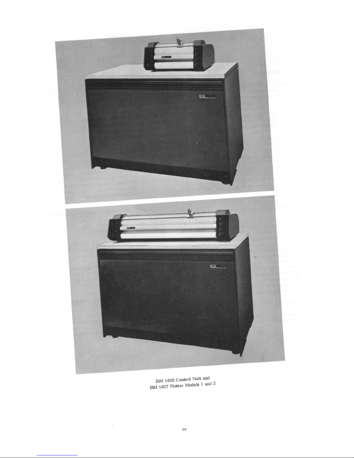
IBM
IBM
1627
1626
Plotter
Control
Models 1
iv
Unit
and
and
2
Page 6
SECTION 1 GENERAL INFORMATION
INTRODUCTION
This
additional.
I/O
circuitry
complete
Unit
and
is
contained
tion
Reference
The
1620
and
and
translates
The
1626
paper
tape
to
the
1620
fact
precludes
with
the
as
description
the
IBM 1627
in
1626
Control
1627.
it
is
designed
code
paper
the
IBM 1626-1627.
OPERATION
Data
from
1620
(by digit)
commands.
to
drawing
movement
and
pen
travels
the
is
achieved
also
that
left
pen
remains
to
the
pen
1626
Each
layed
to
The
actual
by
incremental
(x-axis).
horizontally
front
of
acts
as a platen
The
drum
is,
the
and
right.
or
raise
in
opposite
The
drum
status
Plotter
digit
to
the
the
These
movements
of
the
The
the
by
rotation
and the
paper
the
the
and
are
controlled
Control
is
decoded
1627
causes a 1/100"
carriage
ment.The
in
the
and/or
output
motion
record
Features
it
applies
of
Modell
the
IBM
Manual,
Unit
As
such
into
appropriate
to
format.
tape
punch
use
of
core
storage
1626
where
commands
by
recording
pen
on
movement
pen
is
across
plotter.
of
(Figure
pen
moves
Control
pen
from
up
or
down
status.
pen
-carriage
Unit
into a directional
Plotter.
incremental
paper,
or
action
is
shown
Manual
to
the
the
IBM 1626
and
Customer
Form
227-5721.
is
connected
it
accepts
accept
output
Thus,
output
the
IBM 1621
is
it
is
are
the
1627
is
produced
the
paper
of
mounted
the
paper
The
vertical.
the
pin
1-1).
carriage
up
and
is
also
provided
the
paper
state
by
digits
by a 1620
Each
movement
or
pen
up
resulting
in
describes
the
1620
IBM 1626-1627. A
Plotter
Model 2
Engineering
1620 output
plotter
data
the
1626
channel.
in
transferred
translated
then
Control
Plotters
Instruc-
between
data
commands.
in
the
is
connected
This
conjunction
serially
into 1627
converted
the
Plotter.
by
incremental
surface
the
in a carriage
feed
are
down and
until
movements
transferred
signal
or a pen
Figure
(y-axis)
paper
under
as
viewed
plotting
drum,
bi-directional;
the
to
lower
surface.
directed
and
output
instruction.
signal
to
the
of
the
down
from
each
1-2.
that
from
motion
which
pen
The
to
change
the
to
and
plotter
pen
move-
in-
the
moves
the
pen
the
re-
digit
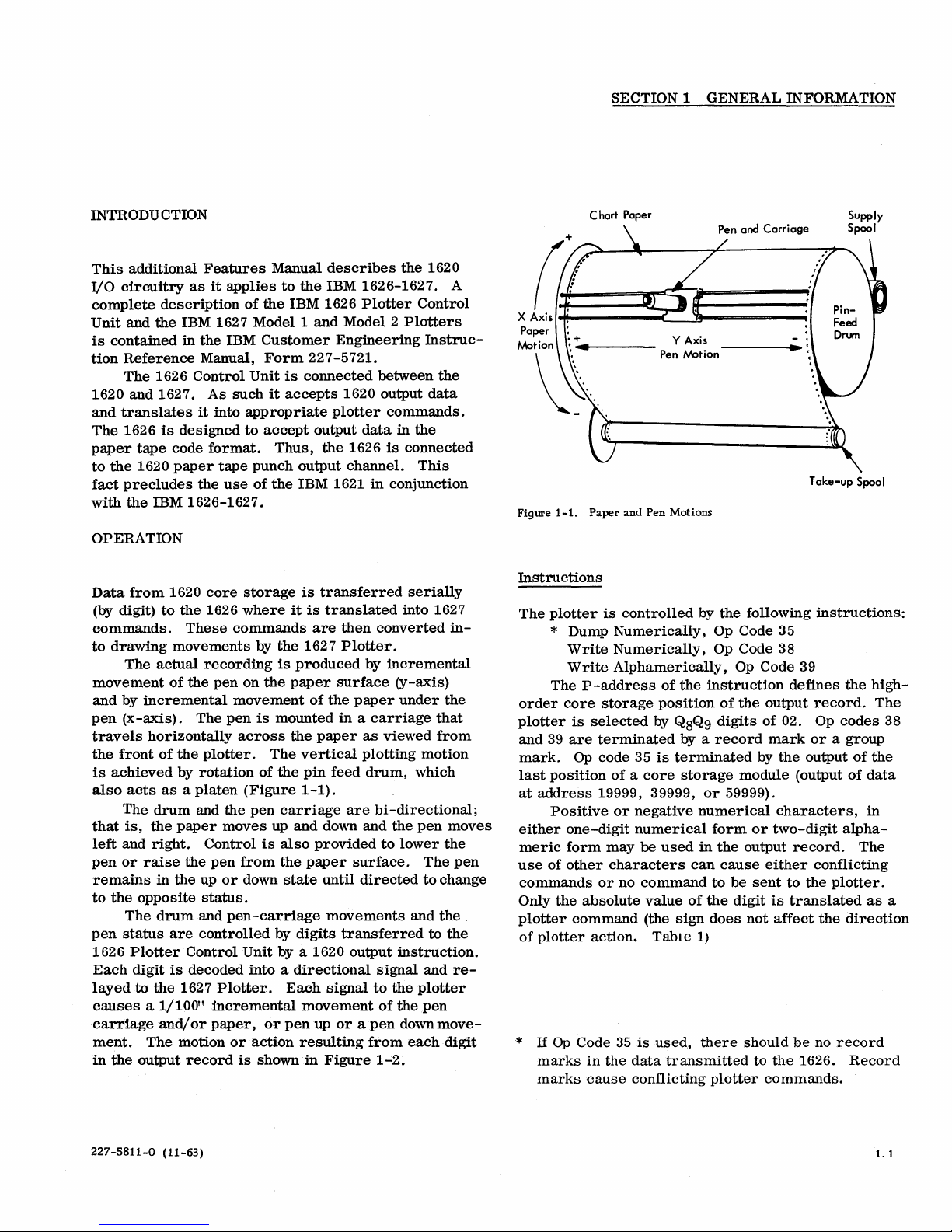
Figure
1-1.
Instructions
The
plotter
* Dump
Write
Write
P-address
The
order
core
plotter
and
mark.
last
at
either
meric
use
commands
Only
plotter
of
*
is
39
are
Op
pOSition
address
Positive
one-digit
form
of
other
the
command
plotter
If
Op
Code
marks
marks
absolute
cause
Chart Paper
Paper
and
Pen
is
controlled
Numerically,
Numerically,
Alphamerically,
of
storage
selected
pOSition
by Q8Q9
terminated
code 35
is
of a core
19999, 39999,
or
negative
numerical
may
be
used
characters
or
no
command
value
(the
action.
in
35
the
Table
is
used,
data
transmitted
conflicting
Motions
by
the
Op Code 35
Op Code 38
the
instruction
of
digits
by
a
record
terminated
storage
or
59999).
numerical
form
in
the
can
cause
to
of
the
sign
does
1)
there
plotter
following
Op Code 39
defines
the
output
of
02. Op
mark
by
the
module
(output
characters,
or
two-digit
output
record.
either
be
sent
to
digit
is
translated
not
affect
should
to
be
the
commands.
Supply
Spool
Take-up Spool
instructions:
the
record.
codes
or
a group
output
of
of
alpha-
The
conflicting
the
plotter.
the
direction
no
record
1626.
Record
high-
The
38
the
data
in
as
a
227-5811-0 (11-63)
1.1
Page 7
put
record
pen
which
The
distance
zontal
or
vertical
produces
results
simultaneous
in a diagonal
moved diagonally
movement.
motion
movement
is
1. 4 times a hori-
of
(Figure
paper
and
1-2).
r,'\
~
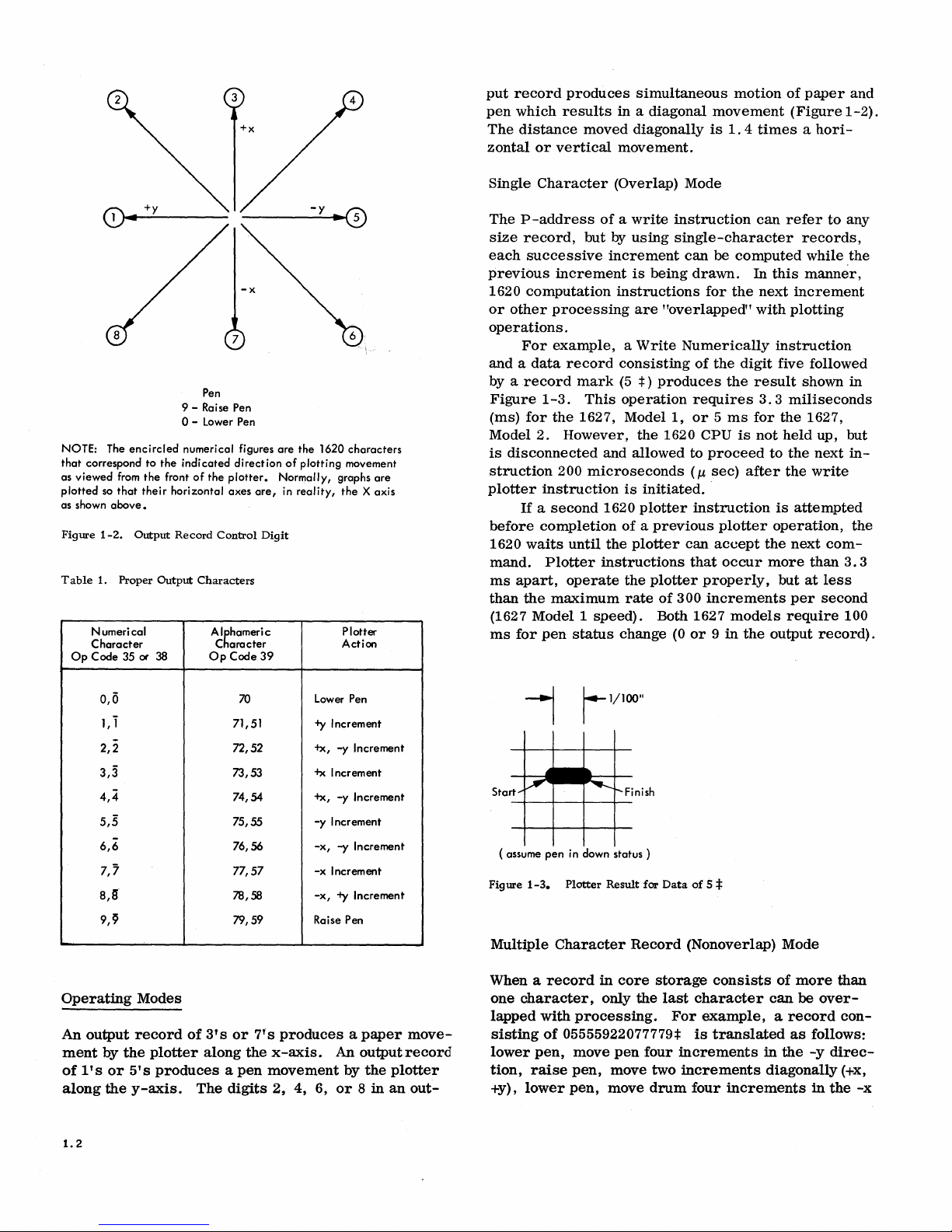
NOTE: The
that
correspond
as
viewed
plotted
so
as shown
Figure
Table
Numerical
Character
Op
Code
above.
1-2.
1. Proper
+y
...
~It-""""'----
Pen
9 - Raise Pen
0-
Lower Pen
encircled
from
that
Output
35 ~ 38
numerical figures
to
the
indicated
the
front
their
horizontal
Record
Output
of
the
Control
Characters
Alhhameric
C
Op
-x
7
direction
plotter.
axes
are,
aracter
Code
are
the
1620
of
plotting
Normally, graphs
in
reality,
Digit
39
characters
movement
are
the X axis
Plotter
Action
Single
The
size
each
Character
P-address
record,
successive
previous
1620
computation
or
other
processing
operations.
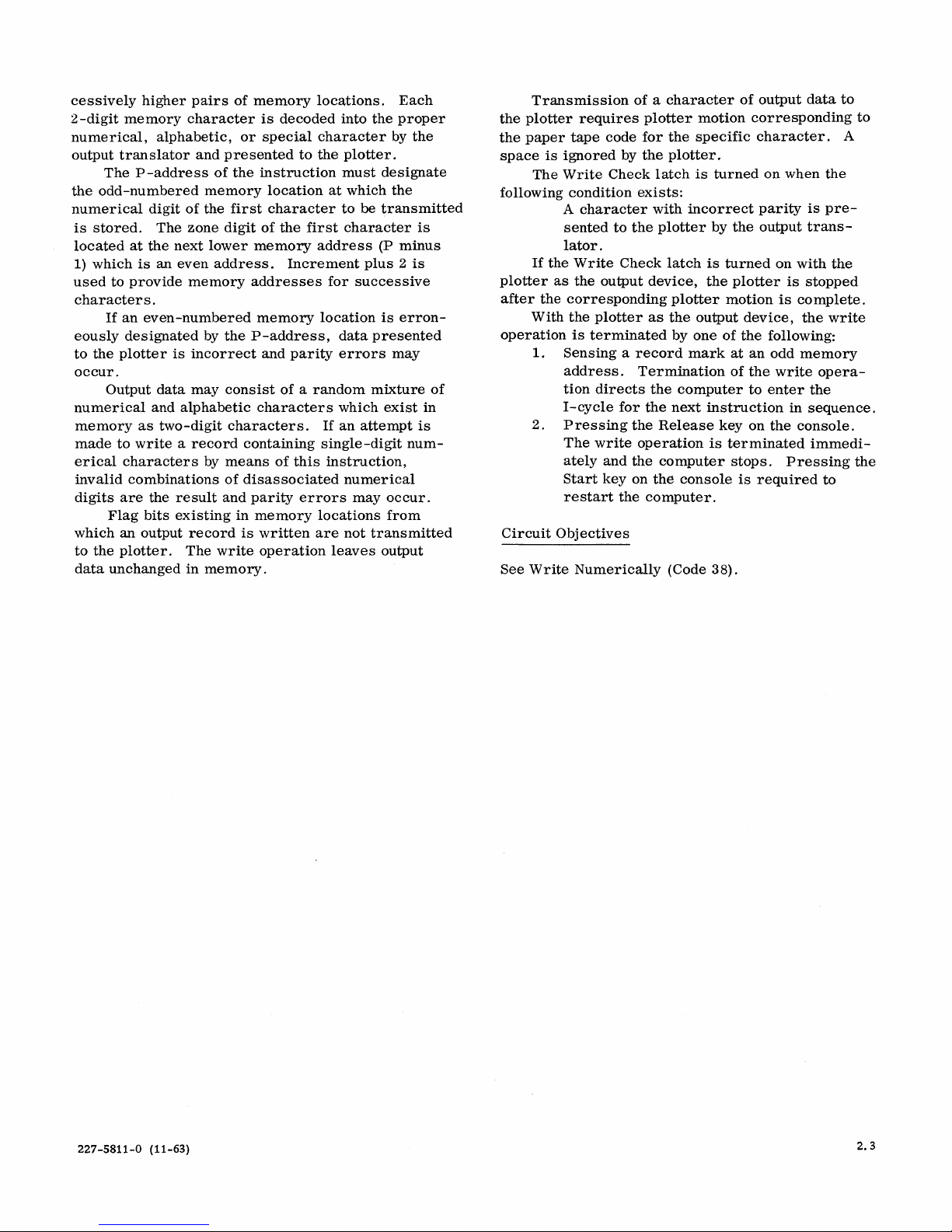
For
example, a Write
and a
data
record
by a
Figure
(ms)
Model
is
1-3.
for
the
2.
disconnected
struction
plotter
before
1620
mand.
ms
than
(1627
ms
instruction
If
a
second
completion
waits
Plotter
apart,
the
maximum
Modell
for
pen
(Overlap) Mode
of a write
but by
increment
increment
record
mark
This
1627,
However,
and allowed to
200
microseconds
1620
until
the
instructions
operate
speed).
status
instruction
using
single-character
can
is
being
drawn.
instructions
are
"overlapped"
Numerically
consisting
(5
:j:)
produces
operation
Modell,
the
is
initiated
plotter
requires
or 5 ms
1620 CPU
(/-l
instruction
of a previous
plotter
can
that
the
plotter
rate
of
300
Both 1627
change
(0
or 9 in
be
computed
for
the
of
the
digit
the
is
proceed
sec)
after
..
plotter
accept
occur
properly,
increments
models
the
can
refer
records,
while
In
this
manner,
next
increment
with
plotting
instruction
five followed
result
for
not
3.3
miliseconds
the
held
to
the
shown in
1627,
the
is
attempted
operation,
the
next
more
than
but
at
per
require
output
to
any
the
up, but
next
in-
write
com-
3. 3
less
second
100
record).
the
0,0
1,1
2,2 72,52
3,3 73,53
4,4
5,5
6,6 76,56
7,7
8,S 78,58
9,C,
Operating
An
output
ment
of
l' s or
along
1.2
Modes
record
by
the
plotter
5' s produces a pen
the
y-axis.
70
71,51
74,54
75,55
77,57
79,59 Raise Pen
of
3' s or
along
The
7' s produces a paper
the
digits
Lower Pen
-+y
Increment
+X,
+x
Increment
+x,
-y
Increment
-x,
-x
Increment
-x,
x-axis.
movement
2,
4,
6,
-y
Increment
-y
Increment
-y
Increment
-+y
Increment
An
outputrecord
by
the
or 8 in
an
move-
plotter
out-
!--I/IOO"
Start Finish
( assume
pen
in down status )
Figure
1-3.
Plotter
Result
Multiple
When a
one
lapped
sisting
lower
tion,
+y),
Character
record
character,
with
processing.
of
05555922077779:1:
pen,
move
raise
pen,
lower
pen,
Record
in
core
only
the
pen
move two
move
for
Data
of
5
:I:
(Nonoverlap) Mode
storage
last
four
consists
character
For
example, a record
is
translated
increments
increments
drum
four
of
can
as
in
the
diagonally
increments
more
be
over-
follows:
-y
in
than
con-
direc-
(+x,
the
-x
Page 8

(paper-up
result
is
In
the
(wait
for
Start
motion)
shown
foregoing
the
plotter).
direction,
in
Figure
example,
The
raise
1-4.
the
duration
tv\otion
pen was
1/100"
T
pen.
1620
will
is
approximately
during time
raised.
The
interlock
plotter
330
the
Table
Table
Output
ms
with
the
1627
Model
2.
2.
Timing
Record
Characters
0
5555
9
22
0 100
7777
9
1627
2.
Timing
Modell
1627-1 1627-2
Plotting Time
100
13
100
7
13
0.3*
333.3
Plotter
is
computed
ms
ms
ms
or
Plotting
"350
as
100
20
100
10
100
20
0.3*
350.3
ms
shown
Time
ms
ms
ms
with
in
Figure
1-4.
Plotter
05555922077779=1:
Result
for
Data
of
* Approxi mately
the
1627
can
act
99.7
on
ms
are
ava
another
plotting instruction.
ilable
for 1620 processing before
227-5811-0 (11-63)
1.3
Page 9

SECTION 2
CmCUIT
DESCRIPTION
WRITE
The
39
tem
circuit
NUMERICALLY (CODE 38-WN)
1626
and
the
Diagrams
description.
Objective
•
Functions
During
are
to
I-cycles,
placed
specify
by 02.
The
from
the
(OR-2)
the
digits
the
and
selected
of
output
Alphabetic
numerical
ory
as
two adj
in
alphameric
vice
as
two
The
in
memory.
Transmission
data
to
the
ponding
The
following
If
the
plotter
after
as
the
block
diagram
function
are
used
Transmit
flag
nated
sively
device
the
numerical
bits,
from
by
the
higher
specified
instruction.
the
in
the
Digit/Branch
the
output
digits
of
output
memory
location
successively
output
output
data
device.
characters,
characters
acent
mode,
numerical
write
operation
of a numerical
plotter
to
the
Write
requires
paper
Check
condition
A
character
to
the
output
Write
the
Check
output
corresponding
for
charts
to
the
P-address
memory
Q8
and
device.
data
higher
device.
are
recorded
that
digits
are
digits.
leaves
tape
latch
exists:
with
device
latch
device,
plotter
Op
Codes
contained
supplement
information,
memory
(OR-2)
locations
by
the
Q8
Q9
digits
register
The
are
transmitted
designated
memory
Flag
bits
special
have
been
because
recorded
output
plotter
code
for
is
turned
incorrect
by
the
is
turned
the
plotter
motion
35, 38,
in
the
the
location
and
and
Q9
of
the
and
plotter
by
the P -address
locations
in
memory
with
the
characters,
stored
the
computer
by
the
data
character
motion
the
specific
on
when
parity
output
on
is
is
and
1620
Sys-
following
including
desig-
succes-
to
the
output
digits
instruction
decoded
is
specified
serially
digits
and
in
mem-
was
output
de-
unchanged
of
output
corres-
digit.
the
is
presented
translator.
with
the
stopped
complete.
of
to
with
by
With
operation
1.
2.
Circuit
Write
Latch
1.
2.
3.
4.
I/o
Memory
1.
2.
3.
4.
5.
6.
7.
I/O
Memory
1.
2.
3.
4.
the
plotter
is
terminated
as
the
by
Sensing a record
Termination
the
computer
next
instruction
Pressing
The
write
ately,
the
Start
to
restart
the
operation
and
key
the
of
to
Release
the
computer
on
computer
Objectives
(11. 83.
Turned
Turned
detected)
Block
Turn
latch
Control
Turned
a.
Write
to
03.1-10.
on by
1-6.
off
by
I/O
.
''Run Clock"
on (T17D2)
during
1-6
A (11. 83.
on by
the
Latch
set
first
MBR.
b.
Response
Gate
subsequent
Turned
turn
Turn
on.
on
off
Run
during
Clock
cycle.
Read
OR-2.
Write
OR-2
incremented
Turn
on
Character
Gate
Output
channel
Translator
digit
to
punch.
Control
Turned
on by
Latch
I/O
(T11D4) .
Turned
Turn
character
on
off
during
Write
is
Check
detected.
Develops a service
Go
latch
when
the
available
in
MBR.
output
one
mark
the
write
enter
in
sequence.
key
is
the
console
01.
Exit
control.
I/o
Memory
time.
following:
(T1702)
output
latch
output
the
latch
Gate
punch
B (11. 83.
Memory
following
latch
response
output
device,
of
the
following:
from
memory.
operation
the
I-cycles
on
the
terminated
stops.
is
.
51.1).
(Record
08.1-10.
during
character
for
second
characters.
cycle
following
for
one
1.
latch.
to
allow
on
the
paper
08.1-10.
Control
cycle
if
an
to
character
the
directs
for
console.
immedi-
Pressing
then
required
Mark
Control
01.
53.1).
1-6
time
into
machine
the
select
tape
Latch
(T2D3).
even
turn
is
write
the
and
its
05.53.1).
A
parity
on
the
227-5811-0 (11-63)
2.1
Page 10

Go
Latch
1.
2.
3.
Response
1.
2.
3.
4.
Release
1.
2.
3.
(11.
82.12.1-10.
Turned
Memory
Turned
Gates
Gate
Turned
the
Turned
ing
Raise
Control
(record
Turn
detected
Latch
Turned
a
mark
on
Turned
Turns
writing
on by
service
Control
off
by
P3
the
output
Latch
(11.
on by a
plotter.
off
(T2D3)
its
turn
on.
I/o
response
latch
if
mark
not
on
Release
on
the
(11.11.08.1-10.01.49.1).
on
by a Response
plotter
write
(punch EOL)
the
select
off
off
Write
of
data.
channel.
by
I-cycle
01.
S8.1).
response
B).
Response.
translator.
83.16.1-10.01.
P3
response
during
Write
yet
latch
select
operation
Latch
the
to
turn
latch
detected).
if a record
channel.
Gate
when a record
character
Reset.
to
block
signal
cycle
on
I/o
is
is
(I/O
53.1).
from
follow-
Memory
still
on
mark
latch
detected
further
is
during
Functions
The
Dump
from
Write
as
follows:
1.
2.
Termination
computer
tion
in
sequence.
The
module
the
Circuit
See
WRITE
is
dump
Objectives
Write
ALPHAMERICALLY
Numerically
Numerically
Sensing
not
marks
commands.
The
digit
transmitted
to
content
recorded
instruction
Numerically
of a record
terminate
in
dump
in
memory
of
enter
of
operation,
operation,
the
memory
)
operation
to
the
the
dump
the
I-cycles
every
by
the
is
00000.
(Code
Code 35,
Code 38, only
mark
in
dump
operation.
cause
conflicting
is
terminated
location
plotter.
memory
plotter
19999
operation
for
the
location
if
the P address
38
- WN).
(CODE 39 - WA)
memory
when
has
directs
next
instruc-
of
differs
does
(Record
plotter
the
been
the
the
first
of
Write
Check
1.
2.
3.
4.
DUMP NUMERICALLY (CODE
The
1626
the
1620
the
following
Objectives
Turned
if
an
the
Turned
ditions:
a.
b.
Turn
Gate
can
block
Systems
•
Transmit
flag
starting
P
address
location
Latch
(11.
on by
even
number
output
translator.
off
by
Depression
console.
When
tested
Branch
on
the
Write
be
circuit
bits
Check
tested
diagram
Diagrams
numerical
and
at
the
(OR-2)
19999.
83.24.1).
the
write
of
either
of
Check
by a Branch
No
Indicator
Write
Check
indicator
to
cause
and
description.
record
location
and
VR C
error
bits
are
of
the
following
Reset
operation.
light.
circuits
branching.
35--DN)
the
function
are
used
information
marks,
designated
continuing
circuits
presented
key
Indicator
charts
to
supplement
including
from
memory
by
through
con-
on
that
the
or
in
to
The
1626
contained
to
supplement
Objectives
•
With
•
•
Functions
During
instruction
and
is
memory
ory
and
the I -cycles,
decoded
specified
Output
locations
the
P-address
block
in
the
the
the
transmit
digits
from
ted
by
ively
higher
Decode
into
the
special
Record
are
to
specify
by 02.
characters
as
two
designated
diagram
1620
System
following
computer
characters
the
the
P-address
pairs
each
two-digit
proper
character.
the
information
the
placed
adjacent
(OR-2)
and
the
Diagrams
circuit
in
memory
of
numerical,
Q8
and
in
the
Digit/Branch
the
output
are
transmitted
digits
by
the
and
function
descriptions.
alphameric
stored
memory
as
locations
(OR-2)
beginning
continuing
and
memory
alphabetic,
on
the
Q9 digits
device.
P-address
charts
are
used
mode,
two
adjacent
designa-
success-
locations.
character
plotter.
of
the
register
The
plotter
serially
at
the
minus
with
suc-
or
from
mem-
1
2.2
Page 11
cessively
2-digit
memory
numerical,
output
translator
The
the
odd
-numbered
numerical
is
stored.
located
1)
used
which
to
at
provide
character
If
an
eously
to
the
plotter
designated
occur.
Output
numerical
memory
made
to
erical
invalid
digits
characters
combinations
are
Flag
which
an
to
the
plotter.
data
unchanged
higher
pairs
character
alphabetic,
and
presented
P-address
of
memory
digit
of
the
The
zone
digit
the
next
lower
is
an
even
address.
memory
s.
even-numbered
by
the
is
incorrect
data
may
consist
and
alphabetic
as
two-digit
write a record
by
means
of
the
bits
output
result
existing
record
The
write
in
memory.
and
of
memory
is
decoded
or
special
the
instruction
location
first
character
of
the
memory
Increment
addresses
memory
P-address,
and
parity
of a random
characters
characters.
containing
of
disassociated
parity
in
memory
is
written
operation
locations.
character
to
the
at
first
address
for
location
If
single-digit
this
instruction,
errors
locations
are
leaves
into
the
plotter.
must
designate
which
to
be
transmitted
character
(P
plus 2 is
successive
is
data
presented
errors
mixture
which
exist
an
attempt
numerical
may
occur.
from
not
transmitted
output
Each
proper
by
the
the
is
minus
erron-
may
is
num-
in
of
Transmission
the
plotter
the
paper
space
is
The
following
If
the
plotter
after
as
the
With
operation
1.
2.
Circuit
See
Write
of a character
requires
tape
ignored
Write
condition
A
character
sented
code
by
Check
to
the
plotter
for
the
exists:
lator.
Write
Check
the
output
device,
corresponding
the
plotter
is
terminated
as
Sensing a record
address.
tion
I-cycle
Pressing
The
ately
Start
restart
directs
for
write
and
key
the
Termination
the
the
the
operation
the
on
computer.
Objectives
Numerically
motion
the
specific
plotter.
latch
is
with
incorrect
plotter
latch
plotter
the
output
by
one
mark
computer
next
Release
computer
the
console
(Code 38).
of
output
corresponding
character.
turned
on
parity
by
the
output
is
turned
the
plotter
motion
device,
of
the
following:
at
an
odd
of
the
to
enter
instruction
key
on
the
is
terminated
stops.
is
required
data
when
is
trans-
on
with
is
stopped
is
complete.
the
memory
write
the
in
sequence.
console.
immedi-
Pressing
to
to
A
the
pre-
the
write
opera-
the
to
227-5811-0 (11-63)
2.3
Page 12

a
N
CD
-
_ - - - cut here _ _ _ _ _ _ _ _ _ _ _
-.J
I
I
I
I
I
I
I
llrn~
e
International Business Machines Corporation
Data Processing Division
112
East Post Road, White Plains, New
York
L3
 Loading...