

iBeam TE-SSA Owner's Manual

800.221.0932
iBeamUSA.com
460 Walker Street, Holly Hill, FL 32117
TE-SSA
Product Manual
800.221.0932
iBeamUSA.com
460 Walker Street, Holly Hill, FL 32117
TE-SSA
Product Manual
I. Specifications
SENSOR
Effective Pixel
CMOS II
656 X 492
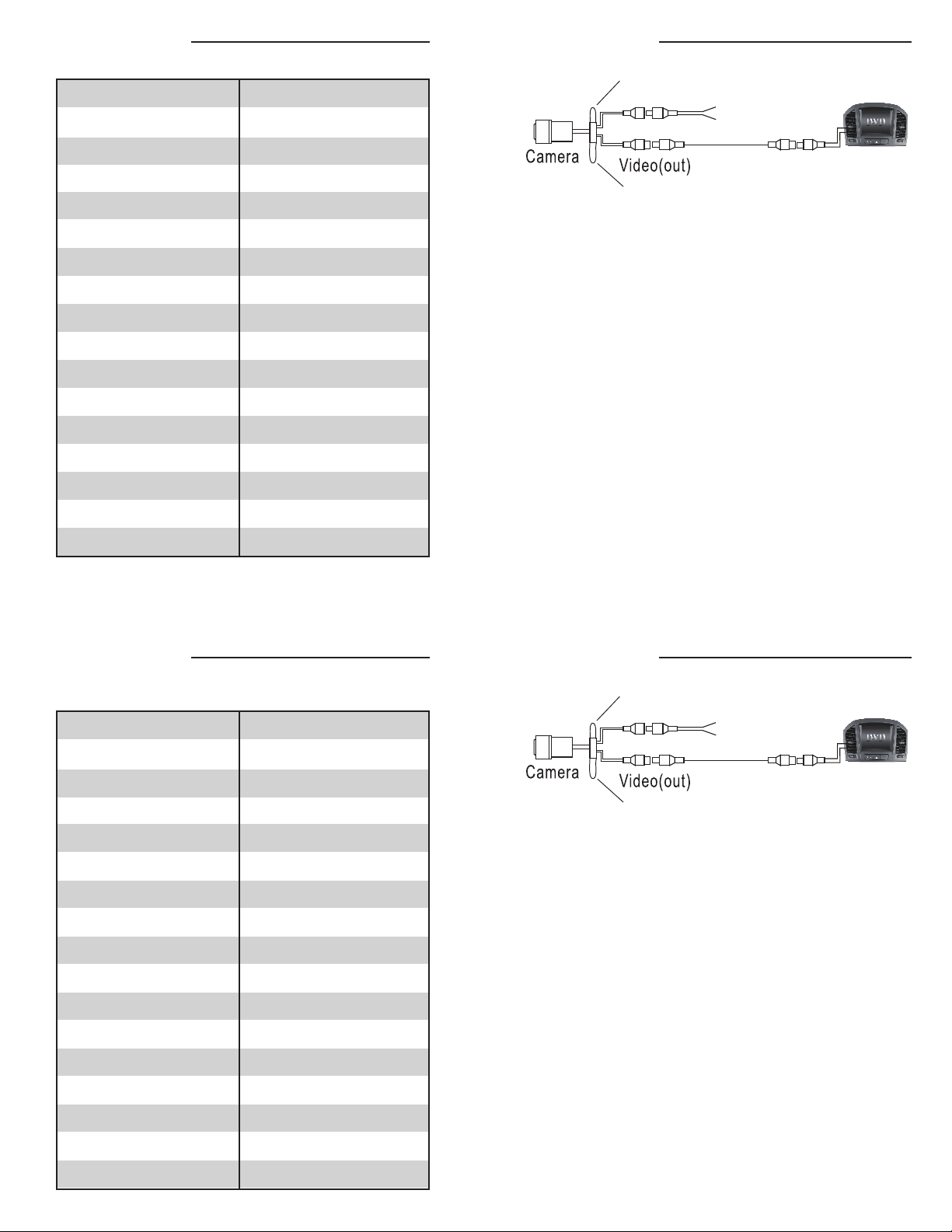
II. Connection
Parking line loop (White)
RED
BLACK
Horizontal Sync Frequency
Vertical Sync Frequency
Scanning System
Sync System
AGC
BLC
Resolution
S/N Ratio
Current Consumption
Power Supply
Operating Temperature
Storage Tempurature
Viewing Angle
Water-P roof
Minimum Illumination
15625KHZ
PAL50HZ / NTSC 60HZ
2 : 1 Interlace
Internal
Auto
Auto
420 TV Lines
More Than 48dB
No More 150mA
DC12V ± 10%
-22 ° ~ 176° F
-40° ~ 176° F
170°
IP67
0.5Lux/F1.2(0Lux with LED)
Video (in)
Reverse image loop (Blue)
1) Find a suitable location to surface mount install the camera. Make sure the
camera’s view is unobstructed and be careful not to drill into any wires that
might damage the vehicle. When all connections have been made and before
mounting the camera, verify the camera is working and has good view of the
area. Then mount the camera down with the supplied two screws.
2) Connect the RED wire to the +12 volt reverse wire
3) Connect the BLACK wire to ground (a metal, non-painted surface).
4) Run video cable though vehicle, up to video display. (Avoid placing video
cable where it can get pinched or damaged).
5) Attach the YELLOW video rca to camera’s output and to the reverse camera
input of the radio or video display.
NOTE: The camera comes with the parking assist lines and a normal image view
active. If you want to remove the parking lines or change the image to reverse
image, follow the steps below:
A) Disconnect power to the camera
B) Cut the WHITE loop to remove the parking assist lines, isolate and tape the wires
C) Cut the BLUE loop to reverse the image, isolate and tape the wires
D) Reconnect power to the camera
If the parking assist lines are wanted or the image needs to go back to normal,
just follow the steps above and reconnect the wires.
I. Specifications
SENSOR
Effective Pixel
Horizontal Sync Frequency
Vertical Sync Frequency
Scanning System
Sync System
AGC
BLC
Resolution
S/N Ratio
Current Consumption
Power Supply
Operating Temperature
Storage Tempurature
Viewing Angle
Water-P roof
Minimum Illumination
CMOS II
656 X 492
15625KHZ
PAL50HZ / NTSC 60HZ
2 : 1 Interlace
Internal
Auto
Auto
420 TV Lines
More Than 48dB
No More 150mA
DC12V ± 10%
-22 ° ~ 176° F
-40° ~ 176° F
170°
IP67
0.5Lux/F1.2(0Lux with LED)
II. Connection
Parking line loop (White)
RED
BLACK
Video (in)
Reverse image loop (Blue)
1) Find a suitable location to surface mount install the camera. Make sure the
camera’s view is unobstructed and be careful not to drill into any wires that
might damage the vehicle. When all connections have been made and before
mounting the camera, verify the camera is working and has good view of the
area. Then mount the camera down with the supplied two screws.
2) Connect the RED wire to the +12 volt reverse wire
3) Connect the BLACK wire to ground (a metal, non-painted surface).
4) Run video cable though vehicle, up to video display. (Avoid placing video
cable where it can get pinched or damaged).
5) Attach the YELLOW video rca to camera’s output and to the reverse camera
input of the radio or video display.
NOTE: The camera comes with the parking assist lines and a normal image view
active. If you want to remove the parking lines or change the image to reverse
image, follow the steps below:
A) Disconnect power to the camera
B) Cut the WHITE loop to remove the parking assist lines, isolate and tape the wires
C) Cut the BLUE loop to reverse the image, isolate and tape the wires
D) Reconnect power to the camera
If the parking assist lines are wanted or the image needs to go back to normal,
just follow the steps above and reconnect the wires.
 Loading...