

iBeam TE-4PSKRUB User Manual

III. Learning Function
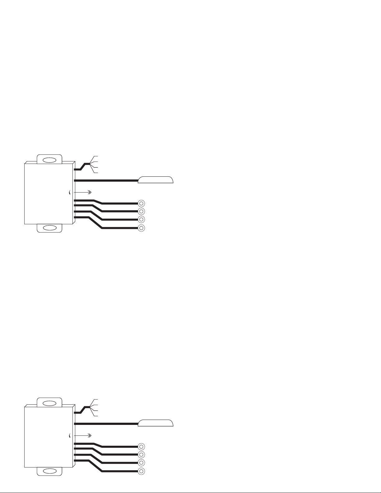
Sensor
D
H
G
F
E
C
B
A
Controller
Sensor
D
H
G
F
E
C
B
A
Controller
If the vehicle has a spare tire or hitch on the back, the
ordinary parking assist system may detect the tire or hitch
which would result in a continuous false alarm. The learning
function on this device can easily remove false alarms and
it will remember the tire or hitch as part of the vehicle,
correcting the alarm. Learning Function Activation: Make
sure there are no objects within 8 feet from the rear of the
vehicle. When the ACC is switched to the ON position, shift
the vehicle from PARK to REVERSE and back continuously
5 times within 10 seconds, after doing this the LED light
on the display will flash three times. The flashing LED will
confirm that the learning function is activated and the
system will remember the tire/hitch/bike holder’s, location
automatically. NOTE: When the hitch or tire has been
removed, you will have to relearn the parking assist system
so it knows that obstruction has been removed.
TE-4PSKRUB
Product Manual
Installation
800.221.0932 • iBeamUSA.com
460 Walker Street, Holly Hill, FL 32117
III. Learning Function
If the vehicle has a spare tire or hitch on the back, the
ordinary parking assist system may detect the tire or hitch
which would result in a continuous false alarm. The learning
function on this device can easily remove false alarms and
it will remember the tire or hitch as part of the vehicle,
correcting the alarm. Learning Function Activation: Make
sure there are no objects within 8 feet from the rear of the
vehicle. When the ACC is switched to the ON position, shift
the vehicle from PARK to REVERSE and back continuously
5 times within 10 seconds, after doing this the LED light
on the display will flash three times. The flashing LED will
confirm that the learning function is activated and the
system will remember the tire/hitch/bike holder’s, location
automatically. NOTE: When the hitch or tire has been
removed, you will have to relearn the parking assist system
so it knows that obstruction has been removed.
The iBEAM TE-4PSKRUB parking sensor kit consists
of ultrasonic rubber sensors, a control box and an
LED display. The system detects the distance between
the vehicle and any obstructions with the use of the
ultrasonic rubber sensors mounted in the bumper. The
distance of the obstruction will be displayed in feet on
the LED display and an audible warning will be heard.
The TE-4PSKRUB can be upgraded to an 8 sensor
parking assist kit with the help of the TE-RES rubber
replacement parking sensors (purchased separately),
4 sensors for the front and 4 sensors for the rear.
TE-4PSKRUB
Product Manual
Installation
The iBEAM TE-4PSKRUB parking sensor kit consists
of ultrasonic rubber sensors, a control box and an
LED display. The system detects the distance between
800.221.0932 • iBeamUSA.com
460 Walker Street, Holly Hill, FL 32117
the vehicle and any obstructions with the use of the
ultrasonic rubber sensors mounted in the bumper. The
distance of the obstruction will be displayed in feet on
the LED display and an audible warning will be heard.
The TE-4PSKRUB can be upgraded to an 8 sensor
parking assist kit with the help of the TE-RES rubber
replacement parking sensors (purchased separately),
4 sensors for the front and 4 sensors for the rear.
I. Specifications
A B C D
A B C D
Rated Voltage: 12V (9-16V)
Rated Current: 20mA~200mA
Detecting Distance: Rear (0’ – 5’) Front (0’- 2.5’)
Ultrasonic Frequency: 40Khz
Working Temperature: -22°~176°F
II. Connection
1) Sensors should be 1.5 to 2.5 feet from the ground, and
4” to 7” inches apart from each other (depending on
vehicle application).
2) Install parking sensors by drilling holes out of the back
bumper with the supplied 21mm hole saw bit (make
sure the thicker side of the sensor is facing down, level
with the ground and the UP arrow on the back of the
sensor is facing up), and install parking sensors.
3) The rear sensors A/B/C/D should be installed from left
to right (looking at the bumper). This is also how they
Red Wire: 12 Volt Accessory (+)
Blue Wire: Reverse Light (+)
Gray Wire: Brake Light (+)
Black Wire: Ground
Display Power
Adj
A B C D
Detection Sensitivity Adjustable
Display
should be plugged into the control box. (Example A:
left, B: mid-left, C: mid-right, D: right)
4) Connect the RED wire to the +12 volt accessory wire.
5) Connect the BLUE wire to the +12 volt reverse light wire.
6) Connect the GRAY wire to the +12 volt brake light wire.
7) Connect the BLACK wire to a ground (a metal, nonpainted surface).
8) Plug that wiring harness into the parking sensor control
box (labeled power).
9) Run the audible warning device cable through the
vehicle and mount somewhere in vehicle’s cabin where
the device can be clearly heard with no obstructions
(avoid placing cable where it can get pinched or
damaged) and plug cable into the control box.
10) Plug the LED display into the parking sensor control
box and run the cable through the vehicle and mount
the LED display on the dashboard. (Avoid placing
cable where it can get pinched or damaged).
11) Mount the control box in rear of vehicle in a safe place
away from rain, heat or humidity.
NOTE: 1) The sensitivity of the sensors can be
increased or decreased. Turning the dial clockwise
to turn down sensitivity and turn counterclockwise to turn up the sensitivity.
2) The parking sensors are designed to be used in
vehicles with metal bumpers.
3) The parking sensor kit is used as a parking aid.
Please use your mirrors and look around to avoid
hitting any object.
I. Specifications
Rated Voltage: 12V (9-16V)
Rated Current: 20mA~200mA
Detecting Distance: Rear (0’ – 5’) Front (0’- 2.5’)
Ultrasonic Frequency: 40Khz
Working Temperature: -22°~176°F
II. Connection
1) Sensors should be 1.5 to 2.5 feet from the ground, and
4” to 7” inches apart from each other (depending on
vehicle application).
2) Install parking sensors by drilling holes out of the back
bumper with the supplied 21mm hole saw bit (make
sure the thicker side of the sensor is facing down, level
with the ground and the UP arrow on the back of the
sensor is facing up), and install parking sensors.
3) The rear sensors A/B/C/D should be installed from left
to right (looking at the bumper). This is also how they
Red Wire: 12 Volt Accessory (+)
Blue Wire: Reverse Light (+)
Gray Wire: Brake Light (+)
Black Wire: Ground
Display Power
Adj
A B C D
Detection Sensitivity Adjustable
Display
should be plugged into the control box. (Example A:
left, B: mid-left, C: mid-right, D: right)
4) Connect the RED wire to the +12 volt accessory wire.
5) Connect the BLUE wire to the +12 volt reverse light wire.
6) Connect the GRAY wire to the +12 volt brake light wire.
7) Connect the BLACK wire to a ground (a metal, nonpainted surface).
8) Plug that wiring harness into the parking sensor control
box (labeled power).
9) Run the audible warning device cable through the
vehicle and mount somewhere in vehicle’s cabin where
the device can be clearly heard with no obstructions
(avoid placing cable where it can get pinched or
damaged) and plug cable into the control box.
10) Plug the LED display into the parking sensor control
box and run the cable through the vehicle and mount
the LED display on the dashboard. (Avoid placing
cable where it can get pinched or damaged).
11) Mount the control box in rear of vehicle in a safe place
away from rain, heat or humidity.
NOTE: 1) The sensitivity of the sensors can be
increased or decreased. Turning the dial clockwise
to turn down sensitivity and turn counterclockwise to turn up the sensitivity.
2) The parking sensors are designed to be used in
vehicles with metal bumpers.
3) The parking sensor kit is used as a parking aid.
Please use your mirrors and look around to avoid
hitting any object.
 Loading...