


VFC 15-150, VFC 45-225
MODULATING GAS BOILERS
(Natural Gas or Propane)
WARNING: If the information in this manual is not followed exactly, a re or
explosion may result causing property damage, personal injury, or loss of life.
Do not store or use gasoline or other ammable vapours and liquids or other
combustible materials in the vicinity of this or any other appliance.
WHAT TO DO IF YOU SMELL GAS:
• Do not try to light any appliance.
• Do not touch any electrical switch; do not use any phone in your building.
• Immediately call your gas supplier from a nearby phone. Follow the gas
supplier’s instructions.
• If you cannot reach your gas supplier, call the re department.
Installation and service must be performed by a qualied installer, service
agency or the gas supplier.
This Manual is also available in French - contact IBC or visit our web site www.ibcboiler.com
INSTALLATION AND OPERATING INSTRUCTIONS
www.ibcboiler.com

VFC 15-150, VFC 45-225 MODULATING GAS BOILERS
SAFETY CONSIDERATIONS
WARNING
If the information in this
manual is not followed
exactly, a re or explosion
may result causing property
damage, personal injury, or
loss of life.
Installation, start-up and servicing of IBC boilers must be done with due
care and attention, and should only be performed by competent, qualied,
licensed and trained heating technicians.
Failure to read and comply with all instructions and applicable National
and local codes may result in hazardous conditions that could result in
property damage and injury to occupants which in extreme cases might
result in death.
HAZARDS & PRECAUTIONS
DANGER
Points out an immediately
hazardous situation which
must be avoided in order to
prevent serious injury or
death.
CAUTION
WARNING
Points out a potentially
hazardous situation which
must be avoided to prevent
serious injury or death.
NOTE
Points out a potentially
hazardous situation which
must be avoided to prevent
possible moderate injury and/
or property damage
Points out installation,
maintenance and operation
details that will result in
enhanced efciency, longevity
and proper operation of your
boiler.
BEST PRACTICES
Points out recommendations
for better installation.
Supplied with the boiler - The IBC boiler is shipped with an accessory parts kit
consisting of the following items:
• 1 x Vent connection kit
• 1 x Condensate trap kit
• 1 x 30 psig pressure relief valve
• 1 x Outdoor temperature sensor
2
INSTALLATION AND OPERATION INSTRUCTIONS

VFC 15-150, VFC 45-225 MODULATING GAS BOILERS
SPECIFICATIONS
SPECIFICATION VFC 15-150 VFC 45-225
CSA Input (Natural Gas or Propane) - MBH
CSA Input (Natural Gas or Propane) - kW
CSA Output - MBH
CSA Output - kW
A.F.U.E. 95% 95%
Minimum gas supply pressure (Natural Gas or
Propane) - inch w.c.
Maximum gas supply pressure (Natural Gas or
Propane) - inch w.c.
Power use (120Vac/60Hz) @ full re - Watts
(excluding pumps)
Weight (shipping) - lbs/Kg 165 / 75 168 / 76
Pressure vessel water content - USG/Litres 2.4 / 9 2.4 / 9
Maximum boiler ow rate - USgpm 16 25
Minimum boiler ow rate - USgpm 4 8
Maximum operating water pressure* - psig 80 80
Minimum water pressure - psig 8 8
Normal ue temperature @ 100°F boiler return
water temperature - high re
15 - 150
4.4 - 44
14 - 139
4.1 - 41
3
3
14
14
57 167
100 to 105 °F
37.8 to 40.5°C
45 - 225
13 - 66
41 - 206
12 - 60
3
3
14
14
100 to 105 °F
37.8 to 40.5°C
Normal ue temperature @ 160°F boiler return
water temperature - high re
Approved installation altitude - ASL 0 - 12,000’ 0 - 12,000’
Ambient temperature - Low (°F-°C)
Ambient temperature - High (°F-°C)
Max. relative humidity (non-condensing) 90% 90%
Minimum water temp. 34°F / 1.1°C 34°F / 1.1°C
Maximum water temp. (electronic hi-limit) 190°F / 87.8°C 190°F / 87.8°C
Maximum water temp. (mechanical hi-limit) 200°F / 93.3°C 200°F / 93.3°C
Max. ΔT - supply/return (electronic fence) 40°F 40°F
Maximum equivalent vent length - 2”
Each side (Vent & Air Intake)) - 3”
(Natural Gas or Propane)
Air intake options: either direct vent or indoor
supply
* boilers are shipped with 30 psig pressure relief valve
160 to 165 °F
71.1 to 73.9°C
32°F / 0°C
122°F / 50°C
50’
120’
160 to 165 °F
71.1 to 73.9°C
32°F / 0°C
122°F / 50°C
N/A
240’
INSTALLATION AND OPERATION INSTRUCTIONS
3

VFC 15-150, VFC 45-225 MODULATING GAS BOILERS
THIS PAGE INTENTIONALLY LEFT BLANK
4
INSTALLATION AND OPERATION INSTRUCTIONS

VFC 15-150, VFC 45-225 MODULATING GAS BOILERS
CONTENTS
1.0 INSTALLATION....................................................1-1
1.1 GENERAL ...................................................1-1
1.2 CODE REQUIREMENTS ........................................1-2
1.3 LOCATION ...................................................1-2
1.4 EXHAUST VENTING AND AIR INTAKE.............................1-3
1.5 CONDENSATE REMOVAL......................................1-14
1.6 WATER PIPING ..............................................1-20
1.7 GAS PIPING.................................................1-26
1.8 ELECTRICAL CONNECTIONS ..................................1-27
2.0 IBC BOILER CONTROL.............................................2-1
2.1 GENERAL ...................................................2-1
2.2 CONTROL ...................................................2-1
2.3 CONTROL INTERFACE.........................................2-2
3.0 STARTUP AND COMMISSIONING ....................................3-1
3.1 LIGHTING AND SHUTTING DOWN THE BOILER ....................3-1
3.2 PRIOR TO START-UP ..........................................3-2
3.3 COMMISSIONING .............................................3-2
3.4 FUEL CONVERSION ...........................................3-5
4.0 MAINTENANCE ...................................................4-1
4.1 BOILER MAINTENANCE ........................................4-1
4.2 COMPONENT DESCRIPTION....................................4-4
4.3 GAINING ACCESS TO COMBUSTION CHAMBER, BURNER REMOVAL
INSTRUCTIONS; FAN AND GAS VALVE REMOVAL INSTRUCTIONS ....4-6
5.0 TROUBLESHOOTING ..............................................5-1
5.1 PRELIMINARY CHECKS ........................................5-1
5.2 ELECTRONIC COMPONENTS ...................................5-2
5.3 TROUBLESHOOTING GUIDE....................................5-6
6.0 DIAGRAMS.......................................................6-1
6.1 VFC 15-150 PARTS DIAGRAMS ..................................6-2
6.2 VFC 45-225 PARTS DIAGRAMS ..................................6-4
6.3 ADDITIONAL PARTS DIAGRAMS .................................6-6
6.4 WIRING DIAGRAMS ...........................................6-7
6.5 SEQUENCE OF OPERATIONS ...................................6-9
INSTALLATION AND OPERATION INSTRUCTIONS
5

VFC 15-150, VFC 45-225 MODULATING GAS BOILERS
DANGER
Should overheating occur
or the gas supply fails to
shut off, do not turn off or
disconnect the electrical
supply to the pump. Instead
shut off the gas supply at
a location external to the
appliance.
WARNING
Do not use this boiler if any
part has been under water.
Immediately call a qualied
service technician to inspect
the boiler and to replace any
part of the control system and
any gas control that has been
under water.
CAUTION
Care must be taken to
properly size the boiler for
its intended use. Prolonged
full re run time, over-
sizing or under-sizing,
and incorrect ow rates
through the boiler can lead
to increased maintenance
costs, equipment stress and
premature failure.
WARNING
If the boiler can become
exposed to uid temperatures
below 34°F (1°C), a method of
protection to prevent freezing
of condensate should be
employed. Contact the factory
for further information.
The Installer must carefully read this manual to ensure that all installation
details can be adhered to. Special attention is to be paid to clearances and
access, vent travel and termination, gas supply, condensate removal and
combustion air supply.
The Installer should do a pre-installation check the to ensure that the
following precautions can be observed:
• The boiler should be installed in areas where the combustion air source is
not subject to chemical fouling or agricultural vapours. Exposure to corrosive
chemical fumes such as chlorinated and/or uorinated hydrocarbons can
reduce the life of a boiler. Cleaners, bleaches, air fresheners, refrigerants,
aerosol propellants, dry-cleaning uids, de-greasers and paint-removers all
contain vapours which can form corrosive acid compounds when burned in a
gas ame. Airborne chlorides such as those released with the use of laundry
detergents are also to be avoided. For this reason, the indoor air venting
option using air surrounding the boiler should not be used in a laundry room.
Similarly, ensure any direct vent air source is not adjacent to a clothes dryer
exhaust terminal. Avoid agricultural applications where the boiler and/or the
intake air source are affected by ammonia and/or dust.
• The boiler should be located where water leakage will not result in damage
to the area. If a location such as this cannot be found, a suitable drain pan
should be installed under the appliance. The boiler is not to be installed above
carpeting.
• At a new construction site, or during renovations, action must be taken to
protect the boiler from drywall dust or other construction related contaminants;
combustion air should be drawn from a CLEAN source (e.g. outdoors) and the
boiler should be isolated from interior dust sources. Do not seal boiler case
openings directly when ring - allow for air circulation and ventilation in the
immediate area.
• When the boiler is in operation, the impact of the steam plume normally
experienced at the exhaust terminal of a condensing boiler should be
assessed. Generally, intake and exhaust pipes should terminate at a rooftop
or sterile wall location. Boiler condensate is corrosive. Protective measures
must be taken to prevent corrosion damage to metal roofs or other metal
building components in contact with the condensate. Keep exhaust plumes
well away from all building air intakes including those of neighbouring
properties.
• The exhaust outlet should be placed so as to reach 24” minimum above the
down-turned intake - to avoid exhaust re-ingestion.
• For sidewall venting options: Both the inlet and exhaust terminations should
normally be located on the same plane (side) of the building. The elevation of
both pipes can be raised in “periscope style” after passing through the wall to
gain required clearance above grade and snow level.
• If the indoor combustion air option is used, ensure combustion air openings to
the boiler room remain unblocked and free of obstructions.
• Examine the condensate outlet to ensure proper disposal of condensate will
occur during operation. If condensate will be discharged into copper or ferrous
metal drains, ensure acid neutralization is employed.
• Ensure that the pressure relief valve will be installed with no valves or other
means of isolation between its inlet and the boiler. Make sure the relief valve
outlet will be piped with unobstructed piping (minimum 3/4” diameter) to a safe
discharge location.
6
INSTALLATION AND OPERATION INSTRUCTIONS

VFC 15-150, VFC 45-225 MODULATING GAS BOILERS
INSTALLATION1.0
1.1
GENERAL
VFC gas-red modulating boilers are low pressure, fully condensing units having
variable input ranges (a) 15 MBH (15,000 Btu/hr) to 150 MBH (15-150 model,
0 to 12,000’) and (b) 45 MBH to 225 MBH (45-225 model, 0 to 12,000’). The
boilers are approved as “Category IV” vented appliances using either Direct
Vent (sealed combustion) or indoor combustion air, providing a great degree of
installation exibility.
Figure 1 shows outer case dimensions and piping and electrical holes. Use this
diagram to nd a suitable location for the boiler. See also Section 1.3 Location.
DESCRIPTION SIZE
A Water Outlet 1-1/4" NPT-M
B Water Inlet 1-1/4" NPT-M
C Gas Inlet 1/2" NPT-F
D Knock-outs (6) 1/2"
E Touch Screen Display 2-1/4” x 4”
F Exhaust Vent 4.0" Hole
G Combustion Air 4.0" Hole
Table 1: Connections
Figure 1a: Dimensions / Connections for VFC 15-150 Figure 1b: Dimensions / Connections for VFC 45-225
INSTALLATION
1-1
VFC 15-150, VFC 45-225 MODULATING GAS BOILERS
1.2
1.3
WARNING
Keep boiler area free and clear
of combustible materials,
gasoline, and other ammable
vapours and liquids.
WARNING
Combustion air must not be
drawn from areas containing
corrosive air from swimming
pools or spas, including air
directly next to outdoor pools
and spas.
WARNING
The boiler shall not be exposed
to water leaks from piping or
components located overhead.
This includes condensation
dropping from un-insulated
cold water lines overhead.
CODE REQUIREMENTS
The VFC 15-150 and VFC 45-225 boiler models were tested to and certied
under CSA 4.9-2014 / ANSI Z21.13-2014.
Installation must conform to local codes, or in the absence of these, with the
latest editions of CAN/CGA B149.1 and the Canadian Electrical Code Part 1 CSA
C22.2 No. 1.
In the US, installations must conform to the current National Fuel Gas Code
ANSI Z223.1 and the National Electrical Code ANSI/NFPA 70. Where required
by jurisdiction, installation must conform to the Standard for Controls and Safety
Devices for Automatically Fired Boilers, ANSI/ASME CSD-1. If there is any
conict, then the more stringent requirement will apply.
LOCATION
VFC-series boilers are designed and approved for indoor installation (wall or rack
mounting), with signicant exibility of location provided with the available venting
options. The boiler can be placed in an alcove, basement, closet or utility room.
Surrounding ambient conditions shall be 0°C to 50°C and less than 90% relative
humidity.
Install the boiler in areas where the combustion air source is not subject to
chemical fouling or agricultural vapours. Exposure to corrosive chemical
fumes such as chlorinated and/or uorinated hydrocarbons can reduce
the life of a boiler. Cleaners, bleaches, air fresheners, refrigerants, aerosol
propellants, dry-cleaning uids, de-greasers and paint-removers all contain
vapours which can form corrosive acid compounds when burned in a gas ame.
Airborne chlorides such as those released with the use of laundry detergents
are also to be avoided. For this reason, the indoor air venting option using air
surrounding the boiler should not be used in a laundry room. Similarly, ensure
any direct vent air source is not adjacent to a clothes dryer exhaust terminal.
Avoid agricultural applications where the boiler and/or the intake air source
are affected by ammonia and/or dust.
Locate the boiler where water leakage will not result in damage to the area. If a
location such as this cannot be found, a suitable drain pan should be installed
under the appliance. The boiler is not to be installed above carpeting.
Boiler weight: 150 lbs / 68 kg without water. Use - as a minimum - 4 x #12 size
2" lag screws or 1/4" bolts (with metal mounting systems). Fasteners are to be
attached to solid material capable of supporting the combined weight of the boiler
and piping assembly components.
WARNING
Ensure the gas ignition
system components are
protected from water (dripping,
spraying, rain, etc.) during
appliance operation and when
servicing (pump replacement,
condensate trap servicing,
control replacement, etc.)
1-2
Other factors affecting potential mounting sites:
• Ensure minimum clearance requirements for combustible materials (see
• Minimum 24" clearance at the front and 10” above is recommended for
• At a new construction site, or during renovations, action must be taken
Table 2) are satised.
adequate servicing. Check local codes for additional access and service
clearance requirements.
to protect the boiler from drywall dust or other construction related
contaminants; combustion air should be drawn from a CLEAN source
(e.g. outdoors) and the boiler should be isolated from interior dust
INSTALLATION AND OPERATION INSTRUCTIONS
VFC 15-150, VFC 45-225 MODULATING GAS BOILERS
WARNING
Exposed water piping and
associated components
(relief valves, circulators, etc.)
should not be in contact with
combustible materials. Check
local codes for required
clearances and/or provide
adequate insulation.
1.4
sources. Do not seal boiler case openings directly when ring - allow for
air circulation and ventilation in the immediate area.
DISTANCE FROM
SURFACE
Front 2" 24"
Rear 0" 0"
Left Side 0" 8" (for vent run)
Right Side 2" 18"
Top 6" 10"
Table 2 - Clearance from boiler cabinet
Distance below the boiler of up to 15" is required to provide clearance for
the inlet and exhaust venting together with the required condensation trap.
See page 1-15.
COMBUSTIBLE
SURFACES
RECOMMENDED
DISTANCE FOR
SERVICE
EXHAUST VENTING AND AIR INTAKE
DANGER
Do not common vent the VFC
modulating series boilers
with any other existing or new
appliance.
WARNING
DO NOT MOUNT THIS
BOILER TO HOLLOW
WALL STRUCTURES - The
combined weight of the
boiler, its water contents
and associated piping
components can exceed 225
pounds. Fasteners must be
rated for this strain, and must
be rmly anchored into solid
material that will support this
weight.
Installers are to take all
necessary precautions
to avoid injury during the
installation of this boiler.
It is important to carefully plan the installation to ensure the appropriate
vent materials, travel and termination decisions are incorporated. Specic
attention is warranted to manage the impact of the steam plume normally
experienced at the exhaust terminal of a condensing boiler. Generally,
intake and exhaust pipes should terminate at a rooftop or sterile wall
location, to maximize customer satisfaction. Keep exhaust plumes
well away from all building air intakes including those of neighbouring
properties.
All venting must be installed in accordance with the requirements of the
jurisdiction having authority: in Canada, Part 8, Venting Systems of the B149.110 Code and any other local building codes are to be followed. In the USA
the National Fuel Gas Code, ANSI 223.1, latest edition, prevails. Where there
is a discrepancy between the installation instructions below, and the code
requirements, the more stringent shall apply.
IMPORTANT
When an existing boiler is removed from a common venting system, the common
venting system is likely to be too large for proper venting of the appliances
remaining connected to it.
When resizing any portion of the common venting system, the common venting
system should be resized to approach the minimum size as determined using the
appropriate tables in the National Fuel Gas Code, ANSI Z223.1 - latest edition. In
Canada, use the B149.1-10 Installation Code.
At the time of removal of an existing boiler the following steps shall be followed
with each appliance remaining connected to the common venting system placed
in operation, while the other appliances remaining connected to the common
venting system are not in operation.
• Seal any unused opening in the common venting system.
• Visually inspect the venting system for proper size and horizontal pitch and
INSTALLATION
1-3
VFC 15-150, VFC 45-225 MODULATING GAS BOILERS
determine there is no blockage or restriction, leakage, corrosion and other
deciencies which could cause an unsafe condition.
• Insofar as is practical, close all building doors and windows and all doors
between the space in which the appliances remaining connected to the
common venting system are located and other spaces of the building. Turn
on clothes dryers and any appliance not connected to the common venting
system. Turn on any exhaust fans, such as range hoods and bathroom
exhausts, so they will operate at maximum speed. Do not operate a summer
exhaust fan. Close replace dampers.
• Place in operation the appliance being inspected. Follow the lighting
instructions. Adjust thermostat so appliance will operate continuously.
• After it has been determined that each appliance remaining connected to the
common venting system properly vents when tested as outlined above, return
doors, windows, exhaust fans, replace dampers and any other gas-burning
appliance to their previous conditions of use.
• Any improper operation of the common venting system should be corrected
so the installation conforms with the National Fuel Gas Code, ANSI Z223.1 latest edition. In Canada, all installations must conform with the current CAN/
CGA - B149.1-10 Installation Code and/or local codes.
WARNING
Venting, condensate
drainage, and combustion
air systems for all IBC
boilers must be installed in
compliance with all applicable
codes and the instructions of
their respective Installation
Manuals.
Inspect nished vent and air
piping thoroughly to ensure
all are airtight and comply
with the instructions provided
and with all requirements of
applicable codes.
Failure to comply will result
in severe personal injury or
death.
WARNING
Covering non-metallic vent
pipe and ttings with thermal
insulation shall be prohibited.
1.4.1 Applications
All VFC-series boilers are approved with alternative venting options: either 2-pipe
Direct Vent or single pipe /Indoor Air venting can be used offering exibility to
meet the specic requirements of the installation. With the Direct Vent case,
combustion air is piped directly to the boiler’s air intake from outdoors (see
Section 1.4 for air intake piping requirements). Using the indoor air alternative, air
for combustion is drawn from the indoor air surrounding the boiler.
Provided the maximum overall vent length limit is not exceeded, the installer may
choose to vent the boiler through the wall, directly through the roof or upward
using an existing - but otherwise unused - chimney as a vent raceway.
1.4.2 Exhaust Vent Material
EXHAUST VENT MATERIAL – CANADA
Use Polypropylene (PPs) or CPVC vent systems approved under ULC-S636
Standard for Type BH Gas Venting Systems, or stainless steel Type BH venting
systems. Permitted PPs materials comprise Single Wall Rigid pipe and ttings
and Flexible.
• ULC-S636 CPVC: 90°C (194°F)
• ULC-S636 PPs: 110°C (230°F)
In the standard conguration, VFC series boilers can supply water temperatures
up to 190°F, leaving stack temperatures above the 65°C (149°F) limit for
ULC-S636 approved PVC.
For long vent runs with higher initial exhaust temperature, some jurisdictions
may allow the use of mixed materials for economy: ULC-S636 approved CPVC
for the initial run followed by ULC-S636 approved PVC to the termination (It is
the responsibility of the Installer to conrm that local codes will allow this option).
Ensure appropriate transition glue is used. The installer is responsible to ensure
1-4
INSTALLATION AND OPERATION INSTRUCTIONS

VFC 15-150, VFC 45-225 MODULATING GAS BOILERS
WARNING
Do not mix PPs venting
materials from different
Manufacturers.
These venting materials are
designed to be installed as
part of a complete system.
Failure to comply may result
in severe personal injury or
death.
DANGER
Failure to install PPs adaptor
with retainer clip could cause
release of harmful exhaust
gases into the heated space,
potentially leading to injury
or death.
that sufcient temperature loss is allowed for in the CPVC section to fall below
the limit for PVC, taking into account the highest possible ambient temperature in
the area of vent travel (e.g. boiler room, attic and/or chase).
EXHAUST VENT MATERIAL – USA
IBC strongly recommends that only CPVC or PPs vent component systems
approved under UL1738 (Standard for Venting Systems for Gas Burning
Appliances, Categories II, III and IV), ULC-S636 Standard for Type BH Gas
Venting Systems, or stainless steel Type BH venting systems* are to be used,
but many local jurisdictions in the USA still allow the use of PVC (Sch. 40 ASTM
D1785 or D2665 and ttings) or CPVC (Sch. 40/ASTM F441 with Sch. 80
ttings).
Do not use ABS or any cellular core pipe for exhaust venting.
Use of cellular core PVC (ASTM F891), cellular core CPVC, or Radel®
(polyphenolsulfone) in venting systems shall be prohibited.
The boiler offers 2" venting connections. Fittings are to be used to adapt to
the appropriate diameter – see Vent Travel below. Exhaust venting is to be
connected directly to the 2" NPT male threaded stainless steel tting on the
bottom of the pressure vessel using:
• For CPVC (and in the USA only, PVC) systems a 2" CPVC (USA: 2” PVC
allowed) threaded adaptor or 90° elbow adaptor. A condensate trap formed
using the supplied ttings shall be considered part of the exhaust and installed
near the base of the boiler (see Figure 2).
• for PPs, use IBC’s VFC PPs transition kit as appropriate for the chosen PPs
system:
Figure 1c: PP Vent Adaptor
Assembly
CENTROTHERM INNOFLUE™ M&G DURAVENT POLYPRO™
KIT# P-166A KIT# P-167A
2” Stainless Coupler (190-044) 2” Stainless Coupler (190-044)
2” Stainless Steel Adaptor (250-419) 2” Stainless Steel Adaptor (250-419)
Retainer Clip (180-050) Retainer Clip (180-051) x 2
PPs Transition Fitting (180-037) PPs Transition Fitting (180-040)
N/A PPs Condensate Trap Adaptor (180-060)
Condensate Trap and Hose (180-013) Condensate Trap and Hose (180-013)
Re-Usable Trap Strap (152-004) Re-Usable Trap Strap (152-004)
Table 3: Polypropylene Venk Kits
Combustion air piping is connected at the base of the boiler using a standard
2" PVC (ABS) coupler or elbow (see Section 1.4.7). For PPs intake piping, use
standard PPs : 2”Sch 40 adaptor parts from the respective PPs manufacturers.
Venting shall be supported in accordance with applicable code.
*Manufacturers of stainless steel Type BH venting systems must submit
their approved transition tting to IBC for evaluation and written approval.
INSTALLATION
1-5
VFC 15-150, VFC 45-225 MODULATING GAS BOILERS
1.4.3 Vent Travel
CPVC or PPs (Rigid Single Wall) piping is the standard venting option; with
this, the VFC 15-150 boiler, for example, can be sited up to 50 equivalent feet
from the vent termination using 2” or up to 120’ using 3”. The actual vent travel
allowance is reduced for ttings in accordance with Table 4. – e.g. for an VFC
15-150 using 6 x 90º CPVC elbows, the maximum lineal measure of pipe allowed
using 3” pipe is 72 feet (120’ – (6 x 8’ = 48) = 72’).
For 3” exible PPs, up to 60 actual lineal feet are allowed in a nominally vertical
orientation (>45°). The equivalent length of 3” ex PPs shall be computed using
a multiple of 3:1, eg. 45’ x 3 = 135’ equivalent (for the VFC 45-225). With 45’ of 3”
ex, up to 105’ equivalent of 3” rigid PPs would still be allowed. 2” exible PPs is
not allowed.
EXHAUST PIPE SIZE MAXIMUM EQUIVALENT LENGTH
Sched.40; Rigid PPs
2" (15-150 only) 50' (each side)
3" (15-150) 120'
3" (45-225) 240'
90° vent elbow allow 8' equivalent
45° elbow allow 3’ equivalent
PPs 87-90° elbow allow 8’ equivalent
Flexible PPs
2” Flexible N/A
3” Flexible (VFC 15-150) 60’ (max) actual lineal x 1.5 = equivalent
3” Flexible (VFC 45-225) 60’ (max) actual lineal x 3 = equivalent
Table 4: Maximum exhaust venting length
Note: Unused intake travel cannot be added to the exhaust. Unequal intake
and exhaust piping is allowed (see Section 1.4.8).
Exhaust venting must slope down towards the boiler with a pitch of at least 1/4”
per foot (PPs vent: follow PPs manufacturer requirements) so condensate runs
back towards the trap. Support should be provided for intake and vent piping,
particularly so for horizontal runs (follow local code). Insulate exhaust piping
where it passes through unheated spaces or underground, with appropriate pipe
insulation to prevent freezing of condensates.
Certain installations of the VFC 15-150 model can employ the 2” vent options. We
caution installers when using horizontal runs of 2” pipe. Reason: air friction from the
fast moving exhaust during long burner runs at high-re in a 2” pipe can overcome
gravity on 1/4” / foot vent slope – leaving a pool of condensate at the next upturned
elbow. Pooling can impair the achievement of full high-re rating plate performance
.
If the site requires a horizontal exit immediately below the boiler – bush out to
3" pipe in the downward vertical run immediately below the 2" threaded adaptor,
and elbow to horizontal before splicing in a eld sourced 3" reducing tee for
mounting of the condensate trap; this will slow the exhaust velocity sufciently for
good drainage and reduce “spitting” at the vent termination. In this case, the 3" x
3/4" reducing tee would replace the 2" tee and 2" x 3/4" bushing supplied with the
VFC 15-150 boiler.
1-6
INSTALLATION AND OPERATION INSTRUCTIONS

VFC 15-150, VFC 45-225 MODULATING GAS BOILERS
WARNING
Fill trap with water before
boiler is rst red to prevent
exhaust fumes from entering
room. Never operate the
boiler unless the trap is lled
with water.
Fan control harness plug
Exhaust venting must slope down to the trap/drain with a pitch of at least 1/4" per
foot (PPs vent: follow PPs manufacturer requirements for slope) so condensate
runs towards the trap. Support should be provided for intake and vent piping,
particularly so for horizontal runs (follow local code). Insulate exhaust piping
where it passes through unheated spaces or underground, with appropriate pipe
insulation to prevent freezing of condensates.
Figure 2a: Basic exhaust vent assembly
Figure 2b: Basic exhaust vent assembly
Ensure all venting components are clean of burrs/debris prior to assembly.
Care is to be taken to avoid ingestion into the fan of PVC/ABS debris left in the
combustion air piping.
Unplugging fan control harness plug
will drive the fan into manual high
speed operation for vent leak test
BEST PRACTICES
To reduce the possibility of
expansion noise, allow a 1/4”
gap around the exhaust and
air intake piping.
All joints must be secured. For CPVC in Canada, use ULC-S636 approved CPVC
solvent cement, in accordance with its manufacturer instructions. Follow the
cement manufacturer’s instructions closely when joining various components.For
PPs, connections shall be secured using approved retainer clips supplied by the
respective PPs manufacturer.
All vent connections must be liquid and pressure tight. Prior to ring the boiler,
and before any of the venting run is concealed by the building construction, the
installer must test the exhaust joints under fan pressure with the vent blocked,
using a soap/water solution. Installer must ll condensate trap prior to test.
Remove the fan control harness plug as illustrated in the photos, and then block
the vent outlet so that the vent run will be under maximum fan pressure. Paint all
joints with an approved leak test solution just as you would joints in a gas line,
and make sure there are no leaks. Good practice would suggest that the installer
attach a tag on the vent line near the condensate drain tee indicating the type of
test, the date and the installer’s name.
INSTALLATION
1-7

WARNING
Condensate can cause
corrosion of metal roong
components and other
roong materials. Check
with the builder or roong
contractor to ensure that
materials will be resistant to
acidic condensate. pH levels
can be as low as 3.0
CAUTION
Vent termination clearances
in this section are
code minimum, or IBC
recommended minimum
requirements, and may
be inadequate for your
installation. Building envelope
details must be examined
carefully, and ingress of
moisture into building
structures is to be avoided.
Serious structural damage
may occur if adequate
precautions and clearances
are not allowed for.
VFC 15-150, VFC 45-225 MODULATING GAS BOILERS
1.4.4 Venting Passage Through Ceiling and Floor
• Conrm material meets local codes including re stopping requirements.
•
Pipe clearances - no IBC requirements, but best practice allows a minimum 1/4”
gap around pipes to prevent binding and expansion noise; follow local codes.
• All piping must be liquid and pressure tight.
1.4.5 Rooftop Vent Termination
Rooftop vents must terminate as follows:
• The exhaust pipe can terminate in an open vertical orientation without
concern about rain inltration; this will drain away through a properly
congured condensate trap.
• If used, the intake air pipe is not typically drained, so it must be terminated
with a down-turned elbow (see Figure 3). The intake pipe does not need to
penetrate the roof at the same elevation as the exhaust (as shown); lower
down roof is OK.
• To promote the projection of exhaust away from the building and from the
intake pipe, reduction of 3" pipe to 2" is permitted for a maximum lineal travel
of 3' (e.g. the nal 3') including 2 x 90° elbows on each side.
• Optional bird screen may be placed in a termination tting. Leave unglued,
and hold in place with a short nipple. This permits easy access for cleaning.
• For roof top venting of multiple boiler sets, group all intake terminals together
for a common penetration through a custom cap. Alternatively, place in the
closest proximity achievable using commonly available pipe ashing. Similarly
group the exhaust pipes and place the 2 separate groups of pipes at least 3'
apart (the closest intake and exhaust pipes shall be 36" - or more - apart).
Use the same 24" (minimum) vertical separation for all termination options.
For alternate group terminations, contact the IBC Factory for written guidance.
• DO NOT exhaust vent into a common venting system.
These precautions are to be
observed for neighbouring
structures as well as for the
structure the boiler(s) are
installed in.
Figure 3: Rooftop vent terminal congurations
1-8
INSTALLATION AND OPERATION INSTRUCTIONS

WARNING
It is extremely important to
maintain at least the minimum
separation of exhaust vent
termination from boiler
intake air as illustrated in
Figures 3, 4 and 5. Failure
to do so can result in a
dangerous situation where
exhaust gasses are reingested with combustion
air. Damage to the boiler
can result from a failure to
maintain these separations.
Third party vent termination
kits and concentric wall
penetration kits that do not
maintain these minimum
separations shall NOT be
used. Improper installation
will void the warranty. Do
not use proprietary InnoFlue
or PolyPro PPs sidewall
terminals without specic
written approval from IBC.
VFC 15-150, VFC 45-225 MODULATING GAS BOILERS
1.4.6 Sidewall Vent Termination
Sidewall direct vent applications shall be vented as follows:
• Both the inlet and exhaust terminations should normally be located on the
same plane (side) of the building.
• The exhaust outlet is to be placed so as to reach 24" minimum above the
down-turned intake - to avoid exhaust re-ingestion.
• The elevation of both pipes can be raised in “periscope style” after passing
through the wall, then congured as in Figure 4, to gain required clearance.
• Use a 45° elbow on the exhaust termination to launch the plume up and off
the sidewall, for protection of wall.
• Bird screen of 1/4" stainless steel or plastic mesh is useful to guard against
foreign objects.
To promote the projection of exhaust away from the building and from the intake
pipe, reduction of 3" pipe to 2" is permitted for a maximum lineal travel of 3' including
2 x 90° elbows on each side. This allows for smaller wall penetrations, with sufcient
travel allowance to achieve the minimum exterior conguration as shown above.
Figure 5: Sidewall vent termination - multiple vent piping conguration
INSTALLATION
Figure 4: Sidewall vent termination - piping conguration
1-9

Figure 6: Vent terminal clearances
Figure 7: Prohibited installation
WARNING
In areas of high snowfall,
Users must be advised to
check side wall vent and
air intake terminations on
a regular basis to ensure
blockage does not occur.
VFC 15-150, VFC 45-225 MODULATING GAS BOILERS
For side venting of multiple boiler sets, group all intake terminals together with
4" to 8" lateral spacing, and similarly group the exhaust pipes. Place the 2
groups on the same plane of the building (e.g. north facing wall). Place the 2
groups of pipes at least 3' apart (the closest intake and exhaust pipes shall be
36" - or more – apart. Use same 24" (minimum) vertical separation as displayed
above. Alternately, as long as the boilers are identical models - intake and
exhaust terminals can maintain a minimum of 12” of separation horizontally
from any exhaust or inlet termination of an adjacent boiler. For alternate group
terminations, contact the IBC Factory for written guidance.
Vent terminal clearance minimums are as follows:
• Clearance above grade, veranda, porch, deck or balcony – 12" (0.3m), but
check local code also (anticipated snow levels may supersede).
• Clearance to openable window or door – 36" (0.91m) (USA – 12”)
• Vertical clearance to ventilated sot located above the terminal within a
horizontal distance of 2’ (0.61m) from the centreline of the terminal.
• Clearance to each side of centreline extended above meter/regulator
assembly: - 3' (0.91m) within a height of 15' (4.6m) above the meter/regulator.
• Clearance to service regulator vent outlet: - 3' (0.91m)
• Clearance to non-mechanical air supply inlet to building or the combustion air
intake to any other appliance: - 3' (0.91m) (USA – 12" (0.3m))
• Clearance to a mechanical air supply inlet: - 6’ (1.82m) (USA - 3’ (0.91m)
above if within 10’ (3.1m) horizontally)
• Clearance above paved sidewalk or paved driveway located on public
property: - 7' (2.2m) NOTE: Cannot terminate directly above a paved sidewalk
or paved driveway that is located between two single family dwellings and
serves both dwellings
• Clearance under veranda, porch, deck or balcony: - 12" (0.3m). NOTE:
Prohibited unless fully open on a minimum of two sides below the oor.
• Vents must be installed such that ue gas does not discharge towards
neighbor’s windows, or where personal injury or property damage can occur.
• It is important to ensure proper condensate management from vent
terminations. Condensate shall not be discharged in a manner that will cause
damage to external building nishes or components, or inltrate the building
envelope.
1-10
Figure 9: Vent terminal clearancesFigure 8: Vent terminal clearances
INSTALLATION AND OPERATION INSTRUCTIONS

VFC 15-150, VFC 45-225 MODULATING GAS BOILERS
WARNING
In addition to preventing
ingestion of chemical
contaminants, care must
be taken to ensure air
intake terminals are not
installed in locations where
contamination might occur
due to ingestion of particulate
foreign material (dust, dirt
and debris).
WARNING
Intake air openings must be
congured such that rain
or other forms of moisture
cannot enter the air intake
piping system. Otherwise
serious damage to the boiler
may result.
1.4.7 “Direct Vent” Combustion Air Intake Piping
There are two basic methods of supplying combustion air to an IBC boiler.
The direct vent option uses piping from the outside to supply combustion air
directly to the boiler’s combustion air connection.
NOTE
Care must be taken when
installing air intake piping to
ensure that a “trap” is not
formed in the piping so as to
allow a build-up of water, and
blockage of intake air.
Such blockage will result in a
boiler safety shut-down.
Figure 10: Direct vent - intake, exhaust and condensate removal system
INTAKE PIPE SIZE MAXIMUM EQUIVALENT LENGTH
Sched.40; Rigid PPs
2" (15-150 only) 50' (each side)
3" (15-150) 120'
3" (45-225) 240'
90° vent elbow allow 8' equivalent
45° elbow allow 3’ equivalent
PPs 87-90° elbow use 8’ equivalent
Air Intake Filter (Part #SC100A) allow 8' equivalent
Flexible PPs
2” Flexible N/A
3” Flexible (VFC 15-150) 60’ (max) actual lineal x 1.5 = equivalent
3” Flexible (VFC 45-225) 60’ (max) actual lineal x 3 = equivalent
Table 5: Maximum intake piping length
INSTALLATION
For the inlet air – Schedule 40 PVC, ABS, or PPs piping of any type is permitted.
Use same diameter as Vent pipe, allowing for up to 6 ft actual run of 2” before
any required transition.
NOTE: It is not permitted to add to the exhaust length by transfer of unused
intake allowance.
1-11

WARNING
When using Indoor
Air options, adequate
combustion air must be
supplied to the boiler room
according to the requirements
of all applicable codes.
VFC 15-150, VFC 45-225 MODULATING GAS BOILERS
Combustion air piping is connected at the base of the boiler using a standard 2”
PVC (ABS) coupler or elbow and run horizontally or vertically to the outdoors.
Screen material can be placed at the inlet as appropriate for the environment
(e.g. insects, dust).
For 3” piping, a 3”x 2” bushing is to be used in the inlet piping within 3 feet of
the combustion air line clearance hole at the base of the boiler. Such 3’ interval
of 2” pipe can be treated as 3” pipe without reference to its smaller diameter in
calculation of the maximum allowable vent travel distance. All elbows and tees at
the base of the boiler and at the termination must be included in the calculation.
Care must be taken to ensure adequate separation is maintained between the
air intake inlet and the vent terminal. Refer to the vent terminal conguration
drawings in the Vent Termination section above.
Support should be provided for intake piping, particularly so for horizontal runs
(follow local code).
1.4.8 “Indoor Air” Combustion Air Intake Piping
An “Indoor Combustion Air installation”, as described herein, is one in which air
for combustion is taken from the ambient air around the boiler.
Figure 11: Indoor air - intake, exhaust and condensate removal system
To support combustion, an ample air supply is required. This may require
direct openings in the boiler room to the outside. If the boiler is not in a
room adjacent to an outside wall, air may be ducted from outside wall
openings.
Provisions for combustion and ventilation air must be made as follows:
• in the USA, in accordance with the National Fuel Gas Code, ANSI Z223.1
• in Canada, in compliance with B149.1-10.
1-12
(latest edition), or applicable provisions of the local building codes
INSTALLATION AND OPERATION INSTRUCTIONS

VFC 15-150, VFC 45-225 MODULATING GAS BOILERS
1.4.9 Combustion Air Filtration
NOTE
Combustion fan
blockages can occur when
environmental particulate and
foreign matter contaminants
(leaves, dust, dandelion &
cottonwood uff, etc) are
drawn into the air intake. In
areas where this problem is
suspected to be an issue,
our optional air intake lter
should be installed.
Filters should be checked
and cleaned or replaced on
a regular schedule based on
the severity of the problem.
If combustion air contamination from ingested particulate matter may be a
concern in any installation, an optional air intake lter may be installed. IBC
supplied air intake lters have a known pressure drop and fouling factor and
should be used as a component of the combustion air system according to the
allowable intake length in Table 4.
Figure 12: Optional air intake lter
IBC Part #SC100A - Filter element
alone is IBC Part #180-103
Air intake lter IBC Part #SC100A
INSTALLATION
Figure 13: Direct vent - intake, exhaust and condensate removal system with optional air
intake lter (ltration may also be used on indoor air applications as required)
1.4.10 Closet Installations
For installations in a conned space (such as a closet), ventilation openings may
be needed through a door or wall to prevent excessive heat from building up
inside the space.
The boiler shall not be exposed to ambient conditions above 122°F (50°C) or
below 32°F (0°C).
1-13

VFC 15-150, VFC 45-225 MODULATING GAS BOILERS
1.5
WARNING
Fill trap with water before
boiler is rst red to prevent
exhaust fumes from entering
room. Never operate the
boiler unless the trap is lled
with water.
Failure to comply will result
in severe personal injury or
death.
WARNING
If condensates are to be
discharged into building
drain piping materials that
are subject to corrosion, a
neutralization package must
be used.
CONDENSATE REMOVAL
IBC’s specied vent conguration promotes the safe drainage of moisture from the
boiler and exhaust venting without owing liquids back through the heat exchanger
(as done by other condensing boilers). Reliable system operation requires (1)
proper design and installation of exhaust venting to allow condensate to run back
to the drain/trap; (2) proper trap depth to handle maximum potential pressure
within the vent, and (3) acid neutralization as appropriate. To achieve these:
1. Allow for a 1/4” per foot slope back to the trap connection, with appropriate
hangers to maintain that gradient; do not use 2” pipe on horizontal runs - air
friction from the fast moving exhaust at high re in a 2” pipe can overcome
gravity even with the specied slope, leaving a pool of condensate at the
next upturned elbow; do not transition between pipe diameters on horizontal
vent runs – always place any reducing couplers in the vertical run)
2. Ensure a trap is established as described below.
3. When required, add (and maintain in good condition) a neutralization tank.
1.5.1 Condensate Trap
When installling the condensate trap, please take into account the following:
• Must be piped to within 1” of a drain or be connected to a condensate pump.
• Drainage line must slope down to the drain at a pitch of 1/4” per foot so
condensate runs towards the trap
• If necessary, the drain connection tee can be laid so the main axis is
horizontal; ensure the drain tee is as close as possible to the vent riser to
avoid water bypass and pooling.
• Most installers prefer to run the combustion air intake pipe alongside the vent,
both to the left side of the boiler to keep the area right of the unit clear for
system water piping.
• Use the supplied PVC unions for easy access for cleaning. Locate on the
vertical legs as per Figures 15 and 16. Earlier installations may have a single
union at base of the trap (as shown in Figure 13).
• Condensate traps should be checked every 2 months, and cleaned and
relled as necessary.
CAUTION
When a condensate
neutralization package
is installed, the pH of the
condensate discharge must
be measured on a regular
schedule to ensure the
neutralizing agent is active
and effective.
1-14
INSTALLATION AND OPERATION INSTRUCTIONS

Figure 15: Condensate trap
conguration (double union option
shown)
VFC 15-150, VFC 45-225 MODULATING GAS BOILERS
1.5.1.1 WITH SCHEDULE 40 PLASTIC VENTING SYSTEMS
(E.G. ULC-S636 CPVC)
A condensate trap must be installed near the base of the boiler as shown in Figure
14. The trap is formed using PVC pipe, elbows and threaded union ttings.
disassembly for cleaning
Figure 14: Condensate trap conguration Figure 16: Condensate trap
NOTE: for CPVC vent systems, the connecting tee and bushing should be
formed using CPVC, transitioning to PVC in the wetted section of the trap, where
non-ULC-S636 materials are allowed as this section is not in contact with ue
products. The trap must be installed as follows:
• The trap depth must be 6” min. in height (see Figure 14); with the
conventional vent kit parts supplied with the boiler, approximately 15”
clearance below the boiler is required.
• Use the supplied vent kit parts to establish the trap in the location shown
below. Do not place the drain connection tee directly at the base of the boiler.
1.5.1.2 WITH PPS VENTING SYSTEMS
For connection to PPS venting systems, an IBC VFC PPs transition kit is
required; select the kit corresponding to the brand of PPs venting to be used
at the installation site (see page 1-5). Note this kit is needed to make safe
connection to the boiler’s 2” NPT-M threaded exhaust outlet and to provide for
good drainage from both the boiler and from the external venting run. Ensure
metal retaining clips are applied at each PPs joint in the system, including that
between PPs and the stainless steel coupler, immediately below the boiler ue
outlet. The condensate trap itself is to be installed at the drain outlet provided at
the bottom of the PPs transition tting, as shown in Figure 17.
INSTALLATION
1-15

VFC 15-150, VFC 45-225 MODULATING GAS BOILERS
Figure 17: Condensate trap installation - PPs
Figure 18: IBC Kit #P-166A for Centrotherm PPs (with Centrotherm clips – IBC #180-050)
1-16
INSTALLATION AND OPERATION INSTRUCTIONS

VFC 15-150, VFC 45-225 MODULATING GAS BOILERS
Figure 19: IBC Kit #P-167A for M&G Duravent PPs (with M&G Duravent clips – IBC
#180-051)
Each manufacturer of PPs venting systems has its own unique design for their
metal retaining clips. While they may look very similar, do not mix any such
components between suppliers. IBC supplies these only within the respective
parts kits. Installation steps:
1. With sealant material, attach the stainless coupler and adaptor onto the
boiler’s 2” NPT-M exhaust connection. Take care not to disturb the lower 1” of
the stainless adaptor with your pipe wrench – that must be smooth for good
sealing with the PPs Exhaust Adaptor.
2. Slide a retainer clip (with barb down) up the stainless adaptor, then move the
PPs Exhaust Adaptor into position. Engage the retainer clip.
3.
Build the venting system upward from the PPs Exhaust Adaptor, securing the
venting in accordance with that supplier’s installation instructions and local code
(e.g. to the wall, and amongst all the system parts using their retaining clips).
4. For the M&G Duravent system, next install their Condensate Trap Adaptor
(IBC #180-060) after sliding on the 2nd retaining clip supplied in kit P-167A
(barb down).
5. The transition assembly is now ready for the trap itself:
Undo Drain Spout Compression Nut (E), remove Drain Hose (G) from Trap.
Drain Outlet (F). Place Vacuum breaker cap (J) over the Vacuum breaker
opening and push rmly home. Remove Upper Compression Nut and
Washer (C) and slide over PPs Transition Fitting Drain Outlet (A).
Fill Trap with water, and slide Trap Body (D) over PPs Transition Fitting Drain
Outlet (A).
Attach Drain Hose (G) and tighten Drain Spout Compression Nut (E).
INSTALLATION
1-17

VFC 15-150, VFC 45-225 MODULATING GAS BOILERS
WARNING
The Trap Hook reusable
retaining strap (IBC #152-
004) must be installed
as instructed and all trap
ttings must be tightened as
instructed to prevent leakage
of ue gasses.
Failure to comply may result
in severe personal injury or
death.
NOTE
It is the responsibility of
the installing and/or service
Contractor to advise and
instruct the end User in how
to perform the Trap cleaning
procedure, and to advise
that the Trap be checked at
least every two months and
cleaned as required.
6. Conrm the Drain Spout Compression Nut (E) is secure by applying 10 lbs
of downward force on the trap body (D). Then apply IBC #152-004 Reusable
Strap as shown in Figure 17 to prevent blow-off of the trap during any
delayed ignition event. Ensure the Strap is seated well in the “V” formed
between the main Trap Body (D) and its Trap Drain Outlet (F).
1.5.2 Condensate Trap Assembly - cleaning procedure
1. Turn off the power to the boiler and allow it to cool down.
2. Remove the trap for cleaning:
• for Schedule 40 CPVC/PVC systems, see Figure 16
• for PPs systems, see Figure 20
3. Flush the debris out.
4. Re-assemble trap components, re-ll trap, and rex trap. Ensure the
Reusable Retaining Strap is applied to secure the trap against blow-off on
PPs systems.
1.5.3 Further installation details
• Condensate drain must be piped to within 1” of a drain or be connected to a
condensate pump.
• Drainage line must slope down to the drain at a pitch of 1/4” per foot so
condensate runs towards the drain.
• Condensate traps should be checked every 2 months, and cleaned and
relled as necessary.
Figure 20: Condensate trap
disassembly for cleaning
1-18
Figure 21: Condensate trap drainage
INSTALLATION AND OPERATION INSTRUCTIONS

WARNING
If condensates are to be
discharged into building
drain piping materials that
are subject to corrosion, a
neutralization package must
be used.
CAUTION
When a condensate
neutralization package
is installed, the pH of the
condensate discharge must
be measured on a regular
schedule to ensure the
neutralizing agent is active
and effective.
VFC 15-150, VFC 45-225 MODULATING GAS BOILERS
DANGER
The water in the condensate
neutralizer can cause
severe burns to the skin.
Use extreme caution when
servicing the condensate
neutralizer. Wear protective
gloves and eyewear.
Figure 22: Condensate neutralization tank
INSTALLATION
1-19

VFC 15-150, VFC 45-225 MODULATING GAS BOILERS
1.6
WARNING
During operation, the relief
valve may discharge large
amounts of steam and/or hot
water. Therefore, to reduce
the potential for bodily
injury and property damage,
a discharge line MUST be
installed that it:
1. is connected from the valve outlet
with no intervening valve and
directed downward to a safe point of
discharge.
2. allows complete drainage of both the
valve and the discharge line.
3. is independently supported and
securely anchored so as to avoid
applied stress on the valve.
4. is as short and straight as possible
5. terminates freely to atmosphere
where any discharge will be clearly
visible and is at no risk of freezing.
6. terminates with a plain end which is
not threaded.
7. is constructed of a material suitable
for exposure to temperatures of
375°F or greater.
8. is, over its entire length, of a pipe size
equal to or greater than that of the
valve outlet.
WATER PIPING
1.6.1 General Piping Issues
The VFC modulating series boilers are designed for use within a closed loop,
forced circulation, low pressure system. A 30 psi pressure relief valve (3/4" NPT)
is supplied for eld installation in the ow supply line – see below. An optional 75
Psig relief valve can be used where required on closed loop systems within multilevel buildings. Relief valve discharge piping must terminate between 6" (15cm)
and 12” (30cm) above the oor using plain un-threaded end, or per local Code.
DO NOT CAP, PLUG OR OTHERWISE
OBSTRUCT THE DISCHARGE PIPE
OUTLET!
CAUTION
Installers should inquire of
local water purveyors as to
the suitability of their supply
for use in hydronic heating
systems.
If water quality is
questionable, a local water
treatment expert must
be consulted for testing,
assessment and, if required,
treatment.
Alternatively, water or
hydronic uid of known
quality can be brought to the
site.
Figure 23: Boiler trim options
System piping is connected to the boiler using the 1-1/4" NPT-M threaded ttings.
Unions and gate or ball valves at the boilers supply and return water connections
are recommended to simplify servicing. Un-insulated hot water pipes must be
installed with a minimum 1/4" clearance from combustible materials.
Fluid ll is most often accomplished by using a boiler regulator & ll valve set
at 12 psig or more, with appropriate backow prevention device as required by
local code. This is acceptable in areas where municipal water or well water has
been treated and ltered to remove excessive minerals and sediment, and water
chemistry is known to be suitable for closed loop hydronic systems. In areas where
water quality is in question, or when chemical treatment or glycol is required, other
options should be considered. Follow applicable Codes and good piping practice.
There are a number of boiler feed and pressurization devices on the market
today that may be a better choice than a raw water ll from the mains. When
regular maintenance requires relief valve blow-off, the discharge may be directed
back into the pressurization unit for recycling of boiler uid and chemicals
back into the system. In buildings that may be unoccupied for long periods of
time, pressurization units are useful to prevent ood damage should leakage
occur from any component in the system. An additional benet is that backow
prevention devices are not required when using these devices.
1-20
INSTALLATION AND OPERATION INSTRUCTIONS

VFC 15-150, VFC 45-225 MODULATING GAS BOILERS
Do not place any water connections overhead the boiler; leaks can damage
the fan & controls. If needed, create a shield over the louvered top of the cover,
but allow clearance for airow and service access.
WARNING
Close ll valve after any
addition of water to the
system, to reduce risk of
water escapement.
NOTE
Full sized application
drawings can be downloaded
from our web site.
www.ibcboiler.com
NOTE
For best results, use a Primary: Secondary piping system, with a pumped
boiler loop using 1-1/4" piping for the 15-150 and 1-1/2” for the 45-225. Heat
exchanger head for both models is approx. 7' at 14 gpm, and 12’ at 22 gpm
so an inexpensive fractional horsepower pump is normally adequate. Primary/
Secondary piping ensures adequate ow and de-couples Δ°T issues (boiler vs.
distribution). Aim for a 20° to 30° F Δ°T across the heat exchanger at high re
(there is a boiler protection throttle fence limiting the Δ°T to 40°F).
The boiler, when used
in connection with a
refrigeration system,
must be installed so the
chilled medium is piped in
parallel with the boiler with
appropriate valves to prevent
the chilled medium from
entering the boiler.
NOTE
The boiler piping system of
a hot water boiler connected
to heating coils located in
air handling units where
they may be exposed to
refrigerated air circulation
must be equipped with
ow control valves or other
automatic means to prevent
gravity circulation of the
boiler water during the
cooling cycle.
Figure 24: Basic Primary/Secondary piping concept
INSTALLATION
Figure 25: Important Primary/Secondary piping details
1-21

VFC 15-150, VFC 45-225 MODULATING GAS BOILERS
WARNING
Water quality has a signicant
impact on the lifetime and
performance of an IBC Boiler
heat exchanger.
Improperly prepared water in
a heating circuit may cause
damage to the heat exchanger
through corrosion or fouling.
Repeated or uncontrolled water
lls will increase the potential
for damage.
High levels of dissolved solids
or minerals may precipitate
out of the uid onto the hottest
part of the heat exchanger,
impairing heat transfer and
resulting in overheating and
premature failure. The amount
of solids that may form on the
heat exchanger will depend
on the degree of hardness and
the total water volume in the
system. A high water volume
system with a low hardness
count may cause as much
damage as a system with less
volume and higher hardness, so
it is recommended to treat water
so as to remove all dissolved
solids. Other water chemistry
allowable limits are as follows:
The VFC modulating series boilers are designed to supply up to four different
heating loads with temperatures within the range 34°F to 185°F - to meet three
separately piped loads. Use closely spaced tees to connect each pumped “load”
(e.g. DHW, baseboards or radiant oor) to the primary loop, or employ the use
of a hydraulic separator to isolate the boiler loop from the system and pipe the
system from the secondary side of the separator.
A variety of application drawings showing basic design options are available from
the IBC web site at: www.ibcboiler.com
Figure 26: Primary/Secondary piping concept with hydraulic separator
Acidity pH is to be between 6.6
and 8.5
Chloride is to be less than 125
mg/l
Iron is to be less than 0.3 mg/l
Cu less than 0.1 mg/l
Conductivity is to be less than
400μS/cm (at 25°C)
Hardness is to be 7 Grains or
less
IMPORTANT: Ensure that these
limits are acceptable for the
other water-side components in
the system.
1-22
Figure 27: Important Primary/Secondary piping details with hydraulic separator
Always ensure that loads sensitive to high temperatures are protected using
means such as an aquastat (wired to the boiler’s auxiliary interlocks) or mixing
valve set for maximum limit (say 140°F) to protect radiant oors.
INSTALLATION AND OPERATION INSTRUCTIONS

VFC 15-150, VFC 45-225 MODULATING GAS BOILERS
PRESSURE VESSEL HEAD
Flow rate (gpm) 4 8 12 16 20
Head @ ow (ft wc) 0.7 2.5 5.0 8.3 12.3
NOTE
The Primary (boiler) pump
must be under the control
of the boiler and wired to
the correct yellow and white
wires labelled “Primary” in
the wiring box.
Failure to do so will result
in a no heat condition as the
boiler will interrupt start-up
with a “No Water Flow” error.
WARNING
Do not use automotive-type
ethylene or other types of
automotive glycol antifreeze,
or undiluted antifreeze of
any kind. This may result
in severe boiler damage. It
is the responsibility of the
Installer to ensure that glycol
solutions are formulated to
inhibit corrosion in hydronic
heating systems of mixed
materials. Improper mixtures
and chemical additives may
cause damage to ferrous and
non-ferrous components as
well as non-metallic, wetted
components, normally found
in hydronic systems. Ethylene
glycol is toxic, and may be
prohibited for use by codes
applicable to your installation
location. For environmental
and toxicity reasons, IBC
recommends only using nontoxic propylene glycol.
Table 6: Pressure Vessel Head
Ensure the pump is rated for the design circulating water temperatures; some pumps
have a minimum water temperature rating above the low temperature potential of the
boiler. Following installation, conrm actual performance by measuring Δ°T (under
high and low ow conditions) after establishing the correct ring rate.
We require waterow after burner shutdown to utilize legacy heat – this is
signicant due to the mass of the heat exchanger (40 Kg) plus its 9L internal
water volume. Default software values will run the boiler’s primary pump for up to
5 minutes (300 seconds) after burner shutdown. Secondary pumps can be set to
run up to 15 minutes after burner shutdown (for the last calling load). As shipped,
the default software will run the DHW pump for 5 minutes to place the legacy
heat where it is useful – e.g. in the DHW tank. Any secondary pump can be set
to run for 0 – 900 seconds in the heat purge mode. Guard against deadheading
pumps when all zone valves are closed.
The primary pump must be under the control of the boiler, to allow the boiler’s
ow proving routine to run. The boiler control looks for ow/no ow during a
pump on / off check on each start up. Ensure that temporarily wired primary or
secondary pumps (e.g. wired externally during the system ll/purge phase) are
returned to the boiler’s control terminals. A “No Water Flow” error message will
otherwise be experienced on start-up.
There are two water pressure sensors, located on the boiler’s supply and return
water piping. These act to provide both low water pressure and low water level
cut-off protection and water ow measurement. Schematics for several piping
layouts are provided, and additional drawings are available at www.ibcboiler.com.
Installers shall conform the piping design to one of the provided congurations to
simplify the control application, promote good loads-and- ows management.
The VFC modulating series boilers offer unparalleled matching of heat generation
to radiation. The low minimum ring is better suited to low thermal loads presented
in a typical multi-zoned radiation system. However, where individual zones in a
heating system have loads under 5,000 Btu/hr, the system will still benet through
use of a buffer tank to ensure a controlled supply temperature, and to prevent
short cycling. Buffering should be added on the secondary piping of the relevant
load, to avoid bulking up the thermal mass of the primary piping circuit (and
potentially lengthen the duration of the transition from hot to cool loads).
Propylene glycol solution is commonly used in a closed loop where freeze
protection is required. Its density is lower than that of water, resulting in
lower thermal performance at a given ow and pressure. As a rule of thumb,
a 50%:50% solution of propylene glycol and water will require an increased
system circulation rate (gpm up 10%), and system head (up 20%) to provide
performance equivalent to straight water.
VFC modulating series boilers can be connected directly to a oor of non-oxygen
barrier polybutylene material (PB tubing). For maintenance of warranty on such
systems, we require evidence of a thorough ushing of all loops, plus installation
of a dirt separator or side stream lter. A separator/lter maintenance routine
shall be carried out after the retrot, with lter clearing after the 1st day, 1st week,
month and annually thereafter. Care is to be taken to avoid use of ferrous ttings
and pumps on PB tube systems.
INSTALLATION
1-23
NOTE
This piping drawings in this
manual are simple schematic
guides to a successful
installation. There are many
necessary components not
shown, and details such as
thermal traps are left out so
the drawings have greater
clarity. We require that
our boilers be installed by
licensed and experienced
trades people who are familiar
with the applicable local
and national codes. System
design is to be completed
by an experienced hydronic
designer or Engineer. It is
necessary to carefully read
and follow these installation
instructions along with the
application drawing that ts
your system.
VFC 15-150, VFC 45-225 MODULATING GAS BOILERS
1.6.2 Installation Rules
NOTE: The Boiler Trim element – common to each of the following systems
- includes the pressure relief, ll, expansion tank and air bleed elements. The
primary pump can be located on either the Supply or Return piping sections.
NOTE
VFC boilers are equipped
with a factory installed
pressure sensor-type Low
Water Cut Off system. The
minimum operating system
pressure allowable with this
is 4 psig. Check local codes
if a Low Water Cutoff Device
is required. If so, determine
if this device meets the local
codes.
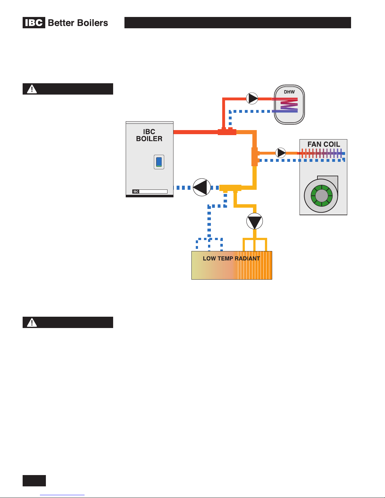
Figure 28: Basic Primary/Secondary, 3 load piping concept
Features of the preferred Primary / Secondary piping system:
1. Good circulating water ow through the boiler irrespective of load or radiation
system head
2. Allows exible ΔT° control in secondary loops
3. Adds to the system’s thermal buffering, to assist in handling small loads and
temperature transition.
This piping conguration requires an extra pump. The VFC modulating series
boilers’ controller hosts wiring terminals and integral relays to simplify installation
and operation of this preferred layout, offsetting such costs.
For optimal performance, place pumps on the supply side of secondary loops
to facilitate air evacuation. Use pumps with internal check valves to avoid ghost
ows and thermal siphoning.
The primary loop temperature may need to transition from a 180°F domestic water
heating load to a 100°F radiant oor requirement. The secondary pumps will swap
off/on simultaneously, provided the pre-set maximum allowable temperature of the
new load is not exceeded. In the case of the typical maximum limit for a radiant
oor (most would enter 140°F); the oor pump would remain off, the boiler shut
down, leaving primary circulation on until the primary loop temperature drops into
the acceptable range for the oor. Temperature sensing is done using thermistors
at the boiler supply and return – no further sensors need to be installed.
1-24
INSTALLATION AND OPERATION INSTRUCTIONS

VFC 15-150, VFC 45-225 MODULATING GAS BOILERS
NOTE
Load Combining is now
available to operate 2
compatible water temperature
loads at the same time.
When using the sequential
load feature of the IBC boiler,
attention must be paid to
the operation of system
components in order to
ensure they are compatible.
Many air handlers (fan
coils) for instance have a
thermostat connection that
will energize an internal relay
to operate the air handler
circulator and its fan on
a call for heat. This may
result in operation of these
components when other
loads are running at a higher
priority, resulting in cold air
blowing, or robbing heat from
another load.
The use of the multi-temperature modulating system is optimized when the need
to shutdown the boiler is reduced or eliminated during the transitional period.
System design enhancements: (a) keep a relatively low thermal mass in the
primary loop, and (b) incorporate a 3-way mixing valve on the “cool” load piping.
If the installation involves small loads, as in typical zoned baseboard heating
applications, use of a buffer tank is recommended. To aid in temperature
transition from hot to cool loads, a 3-way mixing valve can be placed at the
entrance to the cool load (this will also provide oor protection). This will permit
immediate circulation of mixed ow into the cool loop. See separate publication
Application Notes for more detail (available at www.ibcboiler.com or from your
IBC Representative).
Always ensure that loads sensitive to high temperatures (e.g. radiant oor)
are protected using appropriate means such as a manual mixing valve, or an
aquastat (set to130°F, for example) wired to the boiler’s auxiliary interlocks.
Some wiring alteration may
be required to divorce both
of these functions from
thermostat control in favour
of more effective control from
the IBC boiler.
NOTE
For information and details
regarding Multiple Boiler
application, consult our
Technical Notes - Multiple
Boiler Systems. These notes
provide necessary detail on
specic single and multiple
boiler applications “Piping”,
“Wiring” and “Settings”.
(available at www.ibcboiler.
com or from your IBC
Representative).
Figure 29: Two pump, two load - parallel piping concept
Compared with the Primary/Secondary approach, the above design saves one
pump. Lost is the simplicity of constant head and ow at the boiler, with reduced
exibility in the handling of large temperature differentials.
Check valves or thermal traps should be used to isolate both the supply and
return piping for each load - to avoid thermal siphoning and reverse ow.
To ensure adequate water ow through the boiler under high-head / single
zone space heating conditions, a pressure activated bypass or other means of
bypass must be used on any load where the ow rate might drop below minimum
requirements (4 gpm for the 15-150, 8 gpm for the 45-225).
For further information and details, consult our Application Notes – which provide
detail on specic single and multiple boiler applications “Piping”, “Wiring” and
“Settings”. (available at www.ibcboiler.com or from your IBC Representative).
INSTALLATION
1-25

VFC 15-150, VFC 45-225 MODULATING GAS BOILERS
1.7
NOTE
Due to the precision of
modern modulating boilers
it is important to pay special
attention to gas pressure
regulation.
It is essential to check gas
supply pressure to each
boiler with a manometer or
other high-quality precision
measuring device. Pressure
should be monitored before
ring the boiler, when the
regulator is in a “lockup” condition and during
operation, throughout the
boiler’s full modulation range.
Pay special attention to
retrot situations where
existing regulators may have
an over-sized orice and/or
worn seats, causing pressure
“creep” and high lock up
pressures.
A high quality regulator will
maintain constant pressure
above the boiler’s minimum
specication at all ring
rates, and will not exceed the
boiler’s maximum pressure
rating when locked-up with no
load.
GAS PIPING
The boiler requires an inlet gas pressure of at least 3.0" w.c. for natural gas or
propane. For either fuel, the inlet pressure shall be no greater than 14.0" w.c.
Conrm this pressure range is available with your local gas supplier.
The inlet gas connection of the boiler’s gas valve is 1/2" NPT (female).
Adequate gas supply piping shall be provided with no smaller than 1/2" Iron Pipe
Size (IPS), in accordance with the following chart:
MODEL 1/2" IPS 3/4" IPS 1" IPS
VFC 15-150 (Natural Gas) 10 40 130
VFC 15-150 (Propane) 50 180 620
VFC 45-225 (Natural Gas) 5 20 60
VFC 45-225 (Propane) 25 90 290
Table 7: Maximum Pipe Length (ft)
Gas piping must have a sediment trap ahead of the boiler’s gas valve (see Figure
30). A manual shutoff valve must be located outside the boiler, in accordance with
local codes/standards. All threaded joints in gas piping should be made with an
approved piping compound resistant to the action of natural gas/propane. Use
proper hangers to support gas supply piping as per applicable codes.
The boiler must be disconnected or otherwise isolated from the gas supply
during any pressure testing of the system at test pressures in excess of 1/2 psig.
Dissipate test pressure prior to reconnecting. The boiler and its gas piping shall
be leak tested before being placed into operation.
The gas valve is provided with pressure taps to measure gas pressure upstream
(supply pressure) and downstream (manifold pressure) of the gas valve (see
Figure 32). Note that manifold pressure varies slightly in accordance with ring
rates with the modulating series boilers, but will always be close to 0” w.c.
Figure 30: Typical gas piping
1-26
INSTALLATION AND OPERATION INSTRUCTIONS
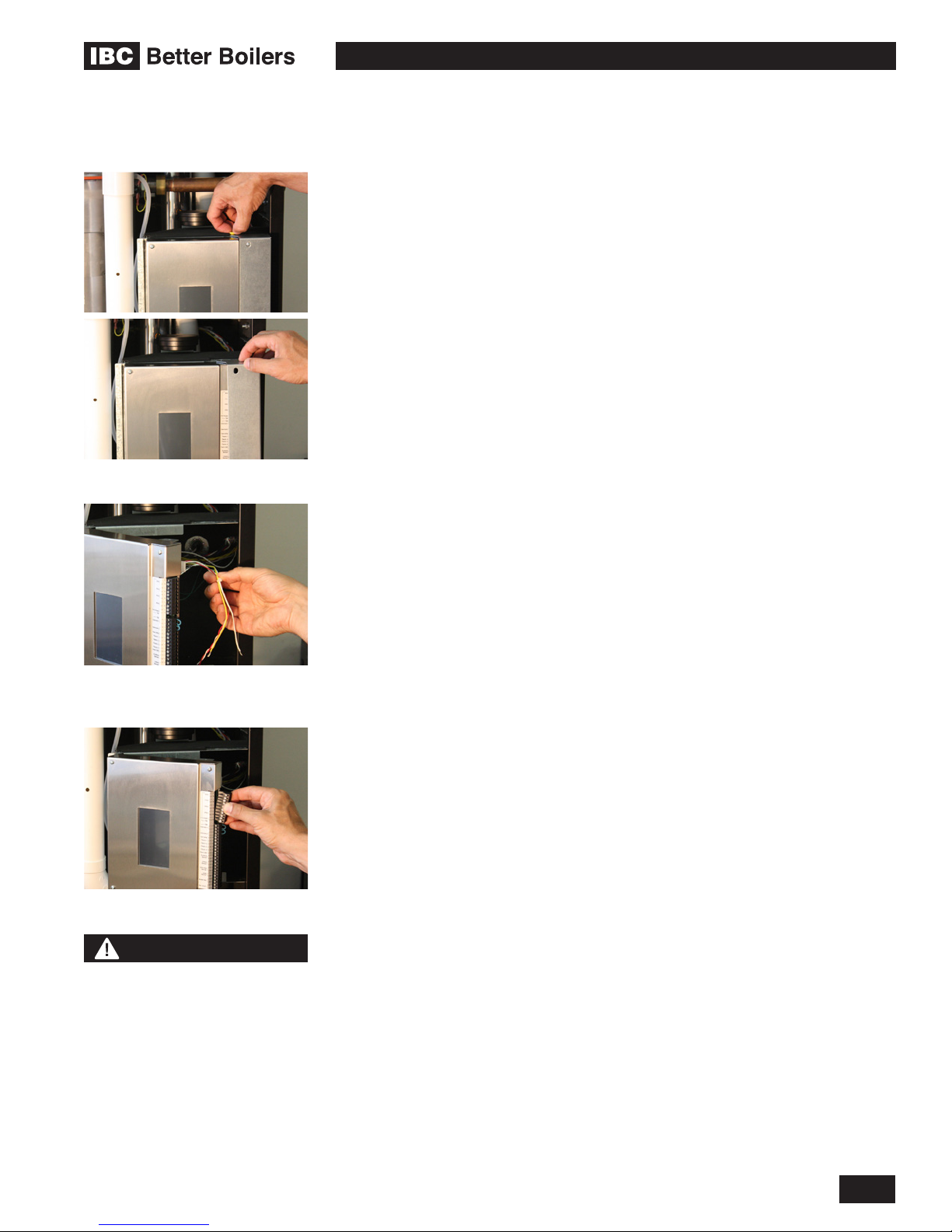
VFC 15-150, VFC 45-225 MODULATING GAS BOILERS
Removing wiring box covers
1.8
ELECTRICAL CONNECTIONS
All Electrical wiring to the boiler (including grounding) must conform to local
electrical codes and/or National Electrical Code, ANS/NFPA No. 70 – latest
edition, or The Canadian Electrical Code, C22.1 - Part 1.
1.8.1 120VAC Line Voltage Hook-up
Line-voltage wiring is done within the eld-wiring box (refer to Figure 31).
Connect the boiler to the grid power using a separate, fused circuit and on/
off switch within sight of the boiler. Use 14-gauge wire in BX cable or conduit
properly anchored to the boiler case for mains supply and pump circuits.
Connect a 120 VAC / 15 amp supply to the “AC IN” tagged leads in the wiring box.
The max. actual draw (with 4 typical residential size pumps) is less than 4 amps.
The 120 VAC power supply to the load pumps (P/V1, P/V2, P/V3, and P/V4) have
been factory installed and connected to P/V-L and P/V-N for your convenience.
If you are to use the P/V relay connections for zone valves then the 120 VAC
connections at P/V-L and P/V-N will have to be removed and properly capped
off. 24VAC can then be applied using an external transformer to supply power to
zone valves. The upper 4 pairs of contacts on this green connector strip are then
powered to manage up to 4 load pumps – the top pair for Load 1, the second pair
for #2 etc. Once the controller is programmed for the respective loads, the boiler
will manage all the loads without need of further relays (for loads up to 1/3 HP;
for more – use a protective relay).
Line voltage leads for power supply,
primary pump and VS output
Line voltage load pump terminals
CAUTION
The internal pump relays are
protected with 5 Amp fuses.
The maximum recommended
load on each fuse is 4 Amps
(80% of rating). The maximum
combined pump load is 10
Amps. Isolation relays or
contactors MUST be used if the
loads exceed these maximums.
The primary pump is connected to the White/Yellow pair labeled Primary Pump.
This lead is factory wired to the controller (and its 120 VAC supply) at the upper
right backside of the controller board – do not attempt to connect the primary
pump to the Pump/Zone Valve Terminal Block along the controller’s right edge
- this is for the secondary pumps and/or zone valves only. Connect the pump’s
Black wire to the Yellow of this pair (switched Hot). The White/ Yellow pair should
be individually capped if the primary pump does not obtain its power from this
pair (e.g. if a variable speed primary pump is connected to the mains power).
Pumps can be switched on/off using the keypad, so there is no need for
temporary pump wiring during system lling / air purging. If pumps are
hard-wired to the panel during the system ll/purge phase, re-wire the
boiler pump to the Primary Pump leads inside the wiring box, to enable the
water ow proving routine to run.
In a new construction application- use a construction thermostat – or jumper
with in-line on/off switch – for on/off management of the boiler. Do not
just pull power from the unit, or its moisture management routine will be
interrupted (fan turns at ultra low rpm for 90 minutes after burner shutdown).
Treat it like a computer, where you do not just pull the plug when done. If a “Low
Airow” error signal shows, check for (and remove) any water in the clear vinyl air
reference tubes. This has been seen occasionally at construction sites where the
boiler has been repeatedly de-powered wet.
The combined current of all pumps connected through the on-board pump relays
should not exceed 10 amps. The control circuit board is protected using on-board
eld replaceable fuses. Each pump is fused with a separate 5 Amp fuse. The
Alarm contact is fused with a 5 Amp fuse and the 24VAC boiler control circuit is
protected with a 2 Amp fuse.
INSTALLATION
1-27

VFC 15-150, VFC 45-225 MODULATING GAS BOILERS
NOTE
The IBC boiler (like any
modern appliance that
contains electronic
equipment), must have a
“clean” power supply, and is
susceptible to power surges
and spikes, lightning strikes
and other forms of severe
electrical “noise”. Power
conditioning equipment
(surge protectors, APC or
UPS devices) may be required
in areas where power quality
is suspect.
1.8.2 Power Quality and Electrical Protection
In areas of unreliable power, appropriate surge protectors and or power
conditioning equipment should be installed in powers supply wiring circuits.
1.8.3 Zone Valve Hook-up
If zone valves rather than pumps are used to manage multiple heating loads, then
24VAC for the zone valves should be provided to the power contacts on the Pump/
Zone Valve Terminal Block. Disconnect the 120 Vac leads connected to PV-L/PV-N
and cap off. Use a separate transformer – the 40VA unit inside the wiring box is for
internal systems only. The individual load/zone valves are then to be wired to their
associated contacts on the secondary pump/zone valve connector. Do not confuse
such “load/zone valves” with similar valves used to segregate a single load type
(e.g. those used on a zoned radiant oor) – see next section.
1.8.4 Thermostat / Sensor Wiring
Dry contacts for thermostats for each of 4 loads are provided as marked on the
lower connector strip (e.g. “Therm 1”). Gang lines from a multiple-zoned load (e.g.
off the end-switches for each radiant oor zone) to present a common thermostat
signal to the controller. Ensure there are no disturbing inuences on the call-
for-heat lines - e.g. no coils to switch an air handler motor. Most power stealing
thermostats can be connected directly to the Therm terminals. See Touch Screen
Controller Manual section 2.1.1 for more detailed instructions.
DANGER
Do not connect thermistor
sensors to “Therm” terminals.
An overheating hazard can
result in serious personal
injury and/or property
damage.
NOTE
The IBC Touch-Screen
controller has the ability
to connect to most power
stealing thermostats. See the
Wiring Diagram for details.
1.8.5 Other Wiring
Other optional low voltage connections to the control board include:
• Two auxiliary interlocks - for external safety devices as may be required by
some jurisdictions, such as a low water cut-off or a low gas pressure cut-out
(for off-grid propane). A oor-protecting aquastat can use one of these, to
cause a full boiler shutdown in the case of excess oor temperature.
• Contacts for indoor and outdoor temperatures sensors associated with Reset
Heating. A 10K ohm thermister for outdoor reset sensing is supplied with the
boiler, to encourage use of this temperature compensating space heating
technique for improved comfort and combustion efciency.
• One pair for a DHW tank sensor. Connect to “DHW S” (not the respective
Therm. 1,2,3,4 location) and the boiler will automatically notice and go to a
smart DHW routine
• One pair of contacts for remote secondary loop temperature control.
• One pair (marked BoilerNet) for network connection – this is used for
connecting multiple VFC modulating units for autonomous staging. See
separate Technical Memo for guidance.
• A nal pair of contacts, to receive a 0-10VDC (default) or 4-20 mA signal
from an external boiler controller- for direct throttle control. The boiler’s own
sensors act as high limits only. User must enter maximum and minimum boiler
supply temperatures.
NOTE: Sensors connected to any sensor input contacts must be of NTC
Thermister - type with a resistance of 10,000 ohms at 25°C and β = 3892. We do
not recommend using 3rd party supplied sensors. Compatible water temperature
sensors and outdoor sensors can be supplied by your IBC distributor.
1-28
INSTALLATION AND OPERATION INSTRUCTIONS

VFC 15-150, VFC 45-225 MODULATING GAS BOILERS
1.8.6 Thermostat Heat Anticipator
IBC “Therm.” contacts draw no power, so an anticipator setting for the thermostat
is not applicable with the VFC modulating series boilers. In the case of a single
temperature / heat load where zone valves are used to manage individual
thermostatically controlled zones, each room thermostat’s heat anticipator should
be adjusted to the current draw of its associated zone valve.
INSTALLATION
Figure 31: Electrical Wiring Connections (full page ladder diagram at back of this manual)
1-29

VFC 15-150, VFC 45-225 MODULATING GAS BOILERS
THIS PAGE INTENTIONALLY LEFT BLANK
1-30
INSTALLATION AND OPERATION INSTRUCTIONS

VFC 15-150, VFC 45-225 MODULATING GAS BOILERS
2.0
2.1
IBC BOILER CONTROLLER
GENERAL
This boiler is equipped with the V-10 Touch Screen controller. The controller
simplies the programing of the boiler while providing greater exibility. For more
detailed instructions, reference the Touch Screen Boiler Controller Manual.
The controller is equipped to provide:
• Control of up to 5 pumps – 1 boiler pump + 4 separate load pumps
• Outdoor Reset control
• Set Point temperature regulation
• Domestic Hot Water (DHW)
• External control via 0-10VDC or 4-20mA signaling
• Alarm dry contacts
• Load Combining – simultaneous operation of 2 similar water temperature
loads
• The control can manage and/or operate in a network of up to 24 IBC VFC or
SL boilers
Some of the new features available in the touch screen control include:
• Express Setup Menu for simple, quick programing
• Software updatable in the eld with a SD card or a USB stick
• Setup conguration back-up and cloning using SD card or USB stick
• Superior warning messages while setting up the control
• Advanced Error messages with visual display on the Home Screen
• Internet/LAN connectivity
• BACnet (with activation)
2.2
WARNING
No sharp or metallic object
should be used on the touch
screen as this will cause
damage. Use only a Stylus or a
clean nger.”
BOILER SYSTEMS AND OPERATION
CONTROL
When the boiler is rst energized, the controller will go through a power up
sequence that will take approximately 90 seconds. During this time the controller
is completing a self-diagnostic and loading all previous settings. In the event of
a power interruption the boiler will automatically resume operation when power
is restored with all the previously stored values. The controller provides overall
management of the boiler operations including;
• Power-up, Self-diagnostics, easy Load parameter adjustments
• Burner operation, safety management systems, Call for Heat management
and Load Priority
• Real time boiler data
• Temperature and throttle operation
• Maintenance of operational and error service logs
• 2-way communication between other IBC boilers and controls
2-1

VFC 15-150, VFC 45-225 MODULATING GAS BOILERS
Operational and historical data may be accessed at any time using the System
Status and Load Proles sections of the control. Error logs are available in the
Diagnostics section and the controller is capable of recording any or all errors
since original power-up complete with the date and time of the error.
2.3
CONTROL INTERFACE
The control interface is provided through a 2-1/4 x 4 inch, color Touch Screen
display. The Touch Screen responds to a light nger touch on the screen. You
can also use a stylus or similar device to operate the touch controls. Do not use
a sharp or metallic object such as a screw driver to operate the control as it could
damage the touch screen.
The controller display is divided into two areas, the screen active area and the
boiler status bar. All screens have an active area consisting of the screen title bar
at the top and a boarder surrounding the active area. At the bottom of the display
there is space reserved for the boiler status bar.
Prior to any interaction with the touch screen the display will be showing the
Home screen that includes details of the current boiler status. If the controller
has been left on the Home screen long enough (user adjustable, 10 minutes by
default) the display with be dimmed to save power.
The control will automatically return to the home screen if left unattended.
The screens will step back one screen at a time in 10 minute increments if the
touch screen has not been touched. The pop-up windows will also step back
automatically in 2 minute intervals.
The boiler status bar indicates if the boiler is in a normal, warning or alarm
state. When no warning or alarm state is present, the bar will be green and the
time will be displayed inside the green area. The bar can also be yellow or red
corresponding a warning or alarm state. Text inside the bar will indicate the
specic warning or alarm present. If more than one alarm is present the text
display will slowly change, rotating though whatever alarms that are present.
2-2
INSTALLATION AND OPERATION INSTRUCTIONS

VFC 15-150, VFC 45-225 MODULATING GAS BOILERS
STARTUP AND COMMISSIONING3.0
3.1 LIGHTING AND SHUTTING DOWN
THE BOILER
STARTUP AND COMMISSIONING
3-1

3.2 PRIOR TO START-UP
Inlet gas supply pressure test port
WARNING
Fill trap with water before boiler
is rst red to prevent exhaust
fumes from entering room.
Never operate the boiler unless
the trap is lled with water.
Failure to comply will result in
severe personal injury or death.
VFC 15-150, VFC 45-225 MODULATING GAS BOILERS
3.2.1 Pre-Ignition Checks
1. Ensure venting system is complete and seal tested. Conrm any common
venting system at the installation site is isolated and independent of the VFC
boiler, that any holes left from removal of a previous boiler have been sealed,
and that any resizing of the old ue has been done. Fill condensation trap to
full neck height.
2. Check water piping system is fully ushed and charged, and that all air
has been discharged through loosened bleed caps. Note it is possible to
switch all pumps on/off from the Touch Screen – without a call for heat.
This greatly simplies system lling and air bleeding (go to Installer Setup,
System Settings, Site Settings, change Manual Pump Purge to “ON”. When
complete, return to Off, or this will automatically occur with a call for heat).
Use a minimum water pressure of 12 psig. And conrm pressure relief valve
is installed and safely drained.
3. Perform a nal check of electrical wiring.
4. Using a manometer, check to see that adequate gas pressure is present
at the inlet gas supply test port. Requirements are minimum 3” w.c and
maximum 14” w.c.
3.3
Manifold pressure test port
DANGER
Making adjustments to
the IBC gas valve without
a properly calibrated gas
combustion analyzer and by
persons who are not trained
and experienced in its use
is forbidden. Failure to use
an analyzer can result in an
immediate hazard.
3.2.2 Test Ignition Safety Shutoff
With the boiler in operation, test the ignition system safety shutoff device by shutting
the gas control valve immediately outside the boiler case. Ensure boiler has shut off
and the appropriate Error information is displayed on the Touch Screen. To restart
boiler, reset power or press “Clear Errors” in the Advanced Diagnostics section.
COMMISSIONING
The VFC modulating boilers are factory calibrated to operate with natural gas (or
propane if so ordered) at sea level. The relevant valve adjustment screws have
been factory sealed using Loctite thread-lock compound, which can be broken
where required. However, no mixture adjustment shall be performed unless
done by a qualied technician using properly functioning combustion
analyzing equipment.
The controller will automatically detect the installations altitude and make the
appropriate adjustments to operate the boiler up to 4,500 feet in elevation without
de-ration. The boiler will automatically de-rate at altitudes above 4,500 feet.
Refer to the IBC Altitude tables for further information.
To verify the proper operation of the gas valve in the eld, the following procedure
can be carried out by a qualied technician (see Figure 32).
1. Turn OFF gas supply to the boiler. With a small (1/8" or 3 mm) at
screwdriver, open the manifold pressure test port by turning its centre- screw
1 full turn counterclockwise. Attach a manometer between the manifold
pressure test port and the reference line and turn on gas to the appliance.
Static manometer reading should be ideally 7” w.c., for Natural Gas and
11” w.c. for Propane. Minimum and maximum static pressure should be
between 5” and 14” w.c. Monitor pressure throughout the commissioning
3-2
INSTALLATION AND OPERATION INSTRUCTIONS

Zero-offset adjustment screw
Gas:Air ratio adjustment screw
VFC 15-150, VFC 45-225 MODULATING GAS BOILERS
procedure. Pressure may droop up to 1” to 2” w.c. at high re but under no
circumstances should it drop below 3” w.c. at the gas valve inlet test port.
2. Allow the boiler to ignite / run against a large load, to maintain high re
3. With the boiler at maximum output, use a 2 mm hex key to adjust the zero-
offset (see Figure 32, “A”) as required to achieve -0.2 to -0.3” wc. This
adjustment should only be necessary if this screw has been tampered with.
4. With a combustion analyzer probe in the ue gas test port, turn the Gas:Air
Ratio Adjustment screw (see Figure 32, “B”) to achieve the appropriate Table
8 mixture target at High Fire. This screw offers very ne adjustment, and
may require several turns. NOTE: This screw has signicant backlash. When
changing direction of turn, it may take up to a full turn before any change
is indicated on the analyzer reading. Clock the gas meter to conrm full
maximum rating plate input.
5. To conrm or adjust the minimum re level settings, Re-dene the load as
“Manual Control”. Use Heat Output in “Congure Load x” to control the output
as needed.
6. At the minimum ring rate, adjust the zero-offset screw (see Figure 32, “A”)
to obtain the target CO2 value. It may be necessary to reduce the output in
stages if this adjustment has been tampered with.
7. Turn boiler off by removing the call for heat (use the Heat Load Conguration
screen to turn load to off if no other ready means available); turn OFF gas
supply to boiler, then remove the manometer connections, and turn the
centre-screw in the manifold pressure test port 1 full turn clockwise. Ensure
fully closed, but not over-tightened. Restore gas and soap test for leaks.
MODEL HIGH FIRE LOW FIRE CO MAX PPM
RANGE TARGET RANGE TARGET
VFC 15-150 (Natural Gas) 8.9 to 9.5% CO
VFC 15-150 (Propane) 10.4 to 10.7% CO
VFC 45-225 (Natural Gas) 8.9 to 9.5% CO
VFC 45-225 (Propane) 10.4 to 10.7% CO
2
2
2
2
9.2% CO
10.6% CO
9.2% CO
10.6% CO
2
2
2
2
7.9 to 8.6% CO
9.0 to 9.8% CO
7.9 to 8.6% CO
9.0 to 9.8% CO
8.4% CO
2
9.6% CO
2
8.4% CO
2
9.6% CO
2
2
2
2
2
< 100
< 150
< 120
< 180
Table 8: Combustion test target ranges - CO2 / Maximum CO
Insertion of ue gas analyzer probeRemoval of ue gas test port plug
STARTUP AND COMMISSIONING
3-3
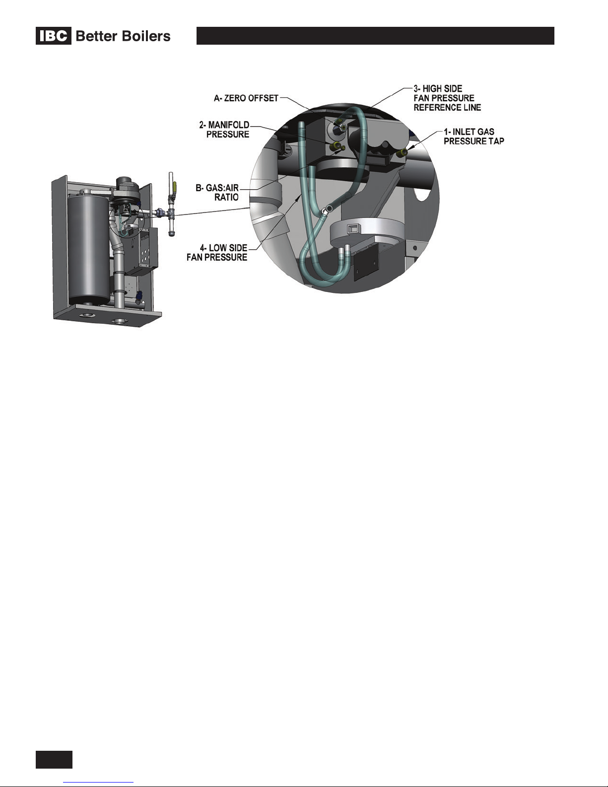
VFC 15-150, VFC 45-225 MODULATING GAS BOILERS
Figure 32: Gas Valve and Pressure Reference System
3-4
INSTALLATION AND OPERATION INSTRUCTIONS

VFC 15-150, VFC 45-225 MODULATING GAS BOILERS
3.4
WARNING
Check the rating plate of
the boiler to ensure it is
congured for the fuel you
are using. If the fuel is
incorrect for the appliance,
a conversion kit must be
ordered from IBC and the gas
valve adjusted accordingly.
Failure to perform the
required fuel conversion can
result in an immediate hazard.
DANGER
Operating any IBC boiler
using a fuel other than the
fuel listed on its rating plate is
prohibited. If the information
in this section related to
conversion to alternate
fuels is not followed exactly,
a dangerous situation can
result, leading to re or
explosion, which may cause
property damage, personal
injury, or loss of life.
FUEL CONVERSION
The VFC Series modulating boiler is factory re-tested to operate with natural
gas, or propane as ordered. The rating plate will be marked to indicate which fuel
the particular boiler has been set up with. Firing a boiler with a fuel other than
what is listed on the rating plate is prohibited unless the following conversion
procedure is completed by a qualied technician.
Refer to the details in the boiler’s current Installation and Operation
Manual, section 3.3 - “COMMISSIONING”.
The Low Fire (Zero-offset) valve and High Fire (Gas: Air) ratio adjustment
will have to be adjusted to attain optimum combustion results whenever fuel
conversion is undertaken however, no mixture adjustment shall be performed
unless done by a qualied technician using properly functioning and
calibrated combustion analyzing equipment.
The following procedure can be carried out by a qualied technician:
1. Ensure you are installing the correct fuel conversion kit for your boiler.
Compare the boiler model number with the Kit# found in Table #9.
2. Ensure the fuel conversion instructions supplied with the fuel conversion kit
are read, understood and followed carefully.
3. Carefully follow the procedures on page 3 of the relevant Fuel Conversion
Instruction document, Combustion Testing and Adjustment.
4. Place the conversion labels associated with the new fuel onto the boiler at
the positions indicated on page 4 of the applicable FUEL CONVERSION
instruction sheet.
5. Carefully follow the “Prior to Start-Up “ - Section 3.2 and “Commissioning” -
Section 3.3 procedures on the preceding pages 3-2 and 3-3.
MODEL NUMBER NATURAL GAS TO
PROPANE
PROPANE TO
NATURAL GAS
STARTUP AND COMMISSIONING
VFC 15-150 P-174 P-176
VFC 45-225 P-174 P-176
Table 9: Fuel Conversion Kits
3-5

VFC 15-150, VFC 45-225 MODULATING GAS BOILERS
THIS PAGE INTENTIONALLY LEFT BLANK
3-6
INSTALLATION AND OPERATION INSTRUCTIONS
VFC 15-150, VFC 45-225 MODULATING GAS BOILERS
4.0
4.1
CAUTION
The owner is responsible for
general care of the boiler.
Improper maintenance of
the boiler may result in a
hazardous condition.
CAUTION
Label all wires prior to
disconnection when servicing
controls. Wiring errors
can cause improper and
dangerous operation.
WARNING
Fill trap with water before
boiler is rst red to prevent
exhaust fumes from entering
room. Never operate the
boiler unless the trap is lled
with water.
Failure to comply will result
in severe personal injury or
death.
MAINTENANCE
BOILER MAINTENANCE
4.1.1 General Care
• Keep combustible materials and ammable liquids and vapours away from the
boiler.
• Keep vent terminals clear of obstructions (snow, dirt, etc.).
4.1.2 Inspection
Inspection of the boiler is to be performed annually by a qualied service
technician.
4.1.3 Venting
• Check vent terminals for and remove any obstructions (e.g. leaves, dust,
other debris).
• Check, and clean or replace intake air lters or screens as required.
• Check for holes or leaks in venting. Replace venting as needed.
• Examine for any signs of moisture caused by sweating intake air pipes;
insulate as required.
• Ensure proper resealing or reinstallation of venting on each servicing.
4.1.4 Condensate Traps
• Condensate trap must be examined every two months to see if cleaning is
necessary (refer to trap cleaning instructions, section 1.5.3 of this manual).
Ensure that trap has been re-lled completely before ring boiler.
• If condensate neutralization is used, check pH level of condensate discharge.
4.1.5 Burner
WARNING
Whenever the burner is
removed for inspection or
boiler servicing, the sealing
gaskets must be examined
and replaced if damaged.
Upon re-assembly, an
approved leak test solution
must be applied around the
burner ange sealing area to
ensure there is no leakage of
combustible gas/air premix.
MAINTENANCE
• Annually, remove burner to inspect for extent of fouling (refer to burner
removal and reassembly instructions, section 4.3 of this manual). Blow clear
using compressed air. Evaluate the magnitude of clearing required, and
establish a reasonable burner inspection schedule. Some boiler / locations
may call for annual service, others showing clean burners will only need
attention every 2 – 5 years. Consider adding air ltration if burner requires
cleaning every year. In alternate years, visually inspect burner through sight
glass. Ensure ame is stable and without excessive uttering. Normal ame
pattern is evenly distributed over the burner surface.
• If burner is operating improperly, remove and clean or replace. Use a CO
analyzer to determine proper combustion. See Table 8 for correct values.
• When re-installing burner, ensure it is inserted so that the seam (that runs
along the length of the metal-bre surface) is placed as far away from the
ignitor as possible (180° rotation arc away). Also conrm spark gap is 1/8".
Conrm visually by removing viewport, turning gas supply OFF, and allowing
the boiler to run through an ignition cycle. Compare the spark length with the
spark rod diameter, which is the same 1/8" (e.g. use the rod as a reference).
2
4-1

VFC 15-150, VFC 45-225 MODULATING GAS BOILERS
CAUTION
The heat exchanger has a
small amount of combustion
chamber insulation
(refractory), which contains
ceramic bers. When
exposed to extremely high
temperatures, the ceramic
bers, which contain
crystalline silica, can be
converted into cristobalite
- which is classied as a
possible human carcinogen.
Care should be taken to
avoid disturbing or damaging
the refractory. If damage
occurs, contact the factory for
directions. Avoid breathing
and contact with skin and
eyes and follow these
precautions:
1.
For conditions of frequent
use or heavy exposure,
respirator protection is
required. Refer to the
“NIOSH Guide to the
Selection and Use of
Particulate Respirators
Certied under 42 CFR
84” for selection and use
of respirators certied
by NIOSH. For the most
current information, NIOSH
can be contacted at 1-800356-4676 or on the web at
www.cdc.gov/niosh.
2. Wear long sleeved, loose
tting clothing, gloves
and eyes protection.
3. Assure adequate
ventilation.
4. Wash with soap and water
after contact.
5. Wash potentially
contaminated clothes
separately from other
laundry and rinse washing
machine thoroughly.
6. Discard used insulation in
an air tight plastic bag.
4.1.6 Heat Exchanger
During burner inspection (with the burner removed), examine the heat exchanger
tubes adjacent to the burner’s normal position. In areas of poor gas quality, there
may be a buildup of black plaque (typically sulfur). Other fouling agents: airborne
dust, debris and volatiles.
Refer to burner removal instructions in Section 4.3 for access to combustion
chamber and heat exchanger. Note that the safety warning regarding burner
refractory on this page must be observed.
4.1.7 Pump
Check that the pump is on in normal operation and that the water Δ°T is
reasonable for a given ring rate (e.g. 10°F between supply and return when
ring at 75,000 Btu/hr. for a VFC 15-150 unit).
4.1.8 Gas Piping
Check for damage or leaks and repair as needed.
4.1.9 Control Module
• Check that boiler operation is consistent with the steps in the Touch Screen
Boiler Controller Manual.
• Check that water temperature targets and setpoint is satisfactory and have
not been adversely amended.
• Check the operating history using the boilers Logs menu and Error Logs
menu. The controller tracks the duty cycle of the boiler in each of the 4 loads
separately. This information can be used to adjust the water temperatures of
each load.
• If a problem exists with the control, consult troubleshooting guide.
4.1.10 Water
• Check water pressure and temperature. There should be no noticeable
change if boiler is functioning normally. Check for any noise in the system.
• Check water piping for damage or leaks and repair as needed.
• Check for 12-15 psig in normal operation, and look to ensure pressure does
not run up toward 30 psig at high temperature. If pressure rises sharply,
consider replacement of expansion tank. Check also for noise at high re,
which may signal water quality problems.
• Check water piping for damage or leaks and repair as needed.
• Water chemistry shall be of a quality generally accepted as suitable for
hydronic applications. See Section 1.6 for details.
• Ensure any direct “city ll” water connections are left in the closed position to
minimize exposure to leaks and ooding.
4.1.11 Freeze Protection
NIOSH stated rst aid:
• Eye contact - Irrigate and
wash immediately.
Check freeze protection. Use only antifreeze made specically for hydronic
systems. Inhibited propylene glycol is recommended. Antifreeze volume must be
between 25-50% of the total volume of water in the system.
• Breathing - Provide fresh
air.
4-2
INSTALLATION AND OPERATION INSTRUCTIONS
VFC 15-150, VFC 45-225 MODULATING GAS BOILERS
WARNING
Do not use automotive-type
ethylene or other types of
automotive glycol antifreeze,
or undiluted antifreeze of
any kind. This may result in
severe boiler damage. It is the
responsibility of the Installer to
ensure that glycol solutions are
formulated to inhibit corrosion
in hydronic heating systems
of mixed materials. Improper
mixtures and chemical
additives may cause damage
to ferrous and non-ferrous
components as well as nonmetallic, wetted components,
normally found in hydronic
systems. Ethylene glycol is
toxic, and may be prohibited
for use by codes applicable
to your installation location.
For environmental and toxicity
reasons, IBC recommends
only using non-toxic propylene
glycol.
4.1.12 Boiler Treatment
• Check consistency of any boiler treatment used (e.g. Furnox™), for
appropriate mixture. Chemical inhibitors are consumed over time, lowering
their density.
• Verify proper operation after servicing.
4.1.13 Relief Valve - Maintenance and Testing
The relief valve manufacturer requires that under normal operating conditions
a “try lever test” must be performed every two months. Under severe service
conditions, or if corrosion and/or deposits are noticed within the valve body,
testing must be performed more often. A “try lever test” must also be performed
at the end of any non-service period.
Test at or near maximum operating pressure by holding the test lever fully open
for at least 5 seconds to ush the valve seat free of sediment and debris. Then
release the lever and permit the valve to snap shut.
If the lever does not activate, or there is not evidence of discharge, discontinue
use of equipment immediately and contact a licensed contractor or qualied
service personnel.
If the relief valve does not completely seal, and uid continues to leak from the
discharge pipe - perform the test again to try and ush any debris that may be
lodged in the valve. If repeated tries fail to stop the leakage, contact a licensed
contractor or qualied service personnel to replace the valve.
CAUTION
Installers should inquire of
local water purveyors as to
the suitability of their supply
for use in hydronic heating
systems. If water quality is
questionable, a local water
treatment expert must
be consulted for testing,
assessment and, if required,
treatment. Alternatively, water
or hydronic uid of known
quality can be brought to the
site.
CAUTION
Before testing the relief valve,
make certain the discharge
pipe is properly connected to
the valve outlet and arranged to
contain and safely dispose of
equipment discharge.
While performing a “try lever test”, a quantity of heat transfer uid will be
discharged from the piping system and the system pressure will drop. This uid
must be replaced. It is highly recommended that a system pressurization unit,
such as an Axiom Industries model MF200 be employed to rell and pressurize
your system. Capture the discharged uid in a container and recycle it by
returning it to the system feeder unit. This is particularly important when your
system contains treatment chemicals or glycol solutions. If the system employs
plain water, the boiler auto ll valve must be turned on in order to recharge the
lost uid.
MAINTENANCE
4-3
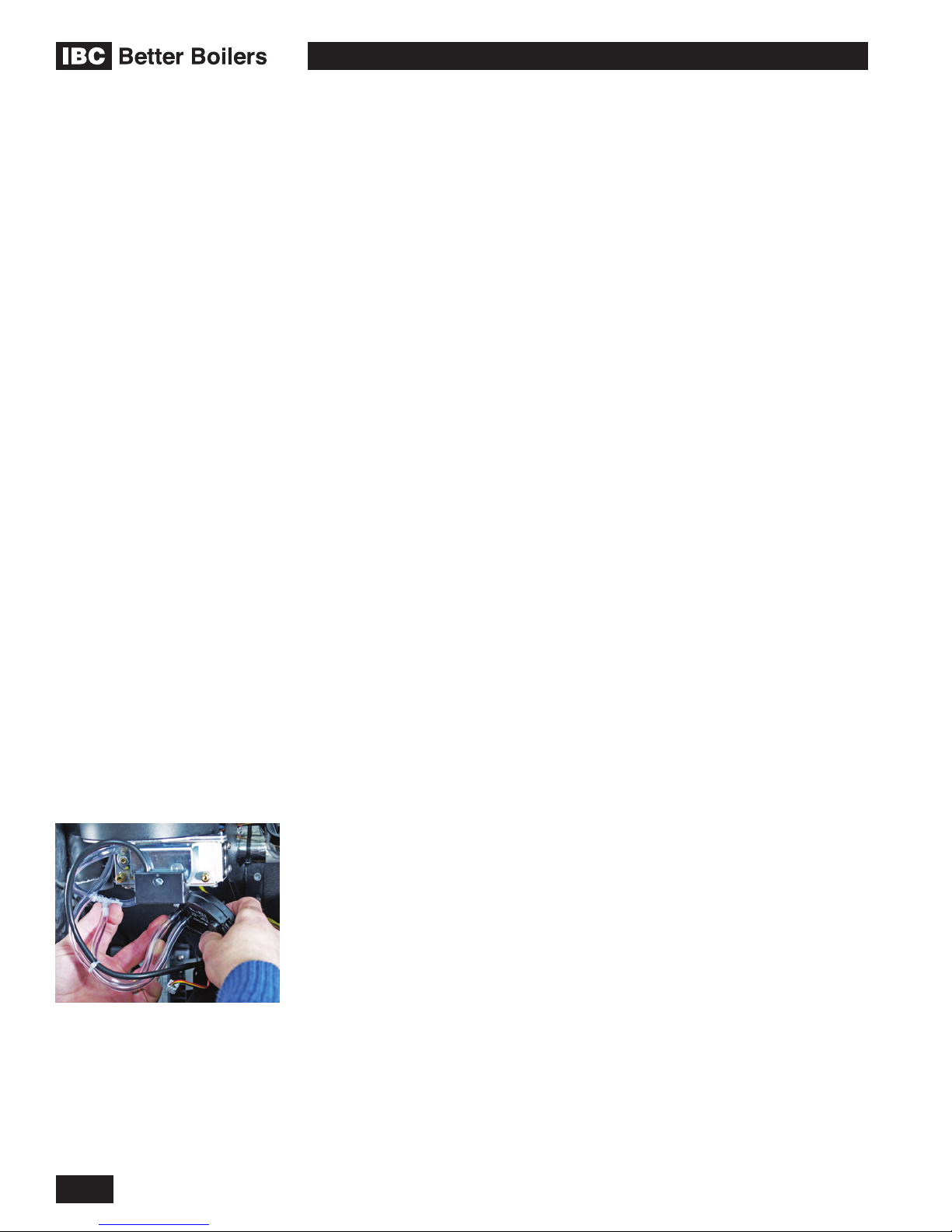
VFC 15-150, VFC 45-225 MODULATING GAS BOILERS
4.2
COMPONENT DESCRIPTION
A diagram of components and their placement can be found at the end of
this manual. To obtain service parts, contact your installer, telephone IBC
Technologies or visit our website at www.ibcboiler.com. The following list provides
a summary description of major components:
4.2.1 Fan/Blower
PART#/TYPE: RG130 – IBC # 240-040 (VFC 15-150)
RG137 – IBC # 240-048 (VFC 45-225)
FUNCTION: Moves combustion air and ue gas products through the boiler
and venting.
INSTALLATION: Fan removal is done at the ange (4 x #10-32 x 7/8” hex head)
and the gas valve (3 x M4 x 30mm Phillips head self tapping screws accessible
for the underside of the gas valve; for improved access – mark and remove vinyl
air reference tubes and black air pressure sensor.
4.2.2 Gas Valve
TYPE: IBC # 180-022
FUNCTION: zero governor gas valve provides strict gas/air mixture control over
the range — 15 - 150 MBH for VFC 15-150 or 45 – 225 MBH for VFC 45-225.
Air pressure sensor removal
showing reference line connections
INSTALLATION: see Section 3.3 - Commissioning, for gas valve adjustments
4.2.3 Direct Spark Ignition Module
TYPE: Fenwal 240-004C
FUNCTION: microprocessor based spark generator and ame proving control
with 15 sec. pre-purge; 3 try before an auto re-setting 1 hour lockout.
INSTALLATION: (see Diagram 6.1-1 for correct position). Use IBC # 180-011
suppression cable as the ignition lead.
4.2.4 Differential Pressure Sensor
TYPE: Air Prove Switch (IBC # 240-003)
FUNCTION: precise measurement of combustion airow for operating control.
INSTALLATION: (see Figure 32 for correct connection of air reference lines).
4-4
INSTALLATION AND OPERATION INSTRUCTIONS

Main combustion components
(clockwise from left) Burner, with
ignitor and V clamp - Fan coupler
- Fan/Blower - Mixing plates &
housing - Gas valve
Combustion group assembly
VFC 15-150, VFC 45-225 MODULATING GAS BOILERS
4.2.5 Water Pressure Sensor
TYPE: Water Pressure (IBC # 240-006)
FUNCTION: water pressure and ow sensing.
INSTALLATION: (see Diagram 6.1-1, and Diagram 6.1-2).
4.2.6 High Limit
PART#/TYPE: IBC # 240-032 High Limit calibrated for 200°F, 15°F differential.
FUNCTION: Shuts boiler off when water temperature exceeds safety limit.
INSTALLATION: (see Diagram 6.1-1 for correct position). Mount with Honeywell
Tradeline #107408 Heat Conductive Compound between the base of the hi-limit
switch and the mounting surface.
4.2.7 Transformer
PART#/TYPE: IBC # 240-008 Primary- 120 VAC; Sec.- 24 V AC; 40VA control
transformer.
FUNCTION: Provides 24 VAC for the control board, for (1) the control / safety
circuit, (2) relays for pump and zone valve control, plus (3) input to DC power
converters for 5 V and 12 V circuits (NB not for use to power external zone
valves).
INSTALLATION: (see Diagram 6.1-1 for correct position).
Control Module removal
4.2.8 Temperature Sensors
PART#/TYPE: IBC # 240-006 Thermistor; 10,000Ω with Beta = 3892
FUNCTION: Senses water temperature. Signals controller to adjust output
according to water temperature.
INSTALLATION: (see Diagram 6.1-1 for correct position).
4.2.9 Control Module
PART#/TYPE: IBC # 500-0044 Touch Screen boiler controller, V10.0
FUNCTION: (see Touch Screen Boiler Controller Manual for an explanation of
controller function).
INSTALLATION: (see Diagram 6.1-1 for correct position). The 4 screws on
the front panel corners secure the cover. To remove the unit from the mounting
brackets, ensure all wires are removed from the connectors on the edge and back
of the control module. Place ngers on the board edge only when handling.
There is a 3V lithium battery (IBC # 240-024) for powering the permanent memory
if AC power is not connected.
On-board eld replaceable fuses (IBC # 240-023) are 5A, slow blow, 5mm x
20mm, and must be replaced using these same specs.
Disconnecting Control Module plugs
MAINTENANCE
4-5

VFC 15-150, VFC 45-225 MODULATING GAS BOILERS
4.3
NOTE
The safety warning regarding
burner refractory on page
4-2 of this manual must be
observed.
Burner Arm Bolts
Fan Screws
Gas Valve Bracket Screws
GAINING ACCESS TO COMBUSTION
CHAMBER, BURNER REMOVAL
INSTRUCTIONS; FAN AND GAS
VALVE REMOVAL INSTRUCTIONS
The installer or service technician can select from three separate routes to gain
access to the burner and heat exchanger:
1. The base method involves removal of the aluminum Fan Coupler (FC) while
leaving the fan and gas valve in-place:
a. Ensure boiler cools down to ambient temperature. Do not drain the boiler
unless freezing conditions are expected during this procedure.
b. Remove the front cover. No tools are required. A ladder or step may be
required to have a clear vertical view of the work area. Do not attempt
to reach from the front without a clear view, as damage to connectors,
screws or refractory may occur.
c. Ensuring the power and gas are shut off, disconnect the ignitor cable and
ground wire from the ignitor
d. Remove the two screws that secure the ignitor to the lid using a # 2
Phillips screwdriver. Carefully remove the ignitor by sliding it straight up.
e. Remove the ignitor gasket and place parts on a clean dry area.
f.
Release the v-clamp, taking care to preserve its gasket for possible reuse.
g. For the VFC 15-150, remove the 4 x 6mm hex socket bolts at the FC:
Fan interface. Three of the 4 bolts are easily dealt with using a regular
6mm Allen key, while the upper (rear) fastener is in a conned space;
start turning with the wrench then complete the job using needle-nose
pliers and/or ngers. This task is best done using a 9” tee-handle hex
key. For the VFC 45-225, remove the 4 bolts and nuts at the FC:Fan
interface using a 5/16” wrench for the bolts and 3/8” wrench for the nuts.
Lift away the Fan Coupler.
h. Remove the burner, noting the alignment of the longitudinal seam of its
metal bre surface relative to the ignitor location (it should be 180° of arc
opposed).
i.
Remove the burner: heat exchanger gasket, and protect for possible reuse.
j. Remove the 4 bolts that attach the heat exchanger lid to the heat
exchanger. A 17 mm open end wrench or socket will be required. Note
alignment for reinstallation. Lift off lid.
k. Note alignment of the inner refractory disk, then carefully lift out and
place on a clean, dry disposable material (paper or plastic).
Using this technique leaves the fan, gas valve and associated electrical
connections exposed to water and/or debris from heat exchanger
cleaning; take precaution by bagging these components.
2. The preferred option for experienced IBC service personnel – for combined
servicing of the HX and swirl plate – involves removal of the FC and fan
together, done as follows:
a. Perform steps 1 (a) to (f) as listed in #1above. Disconnect the 2 power
connections to the fan within step 1(c).
b. Split the fan from the swirl plate/ intake air housing:
i. Remove the 3 Phillips screws which run vertically upwards from the
gas valve into the fan. The rear screw can be challenging - these bolts
can be identied by the spacers under the bolt heads. Best to use an
4-6
INSTALLATION AND OPERATION INSTRUCTIONS

Vellumoid paper
gasket VFC15-150
O-Ring, VFC 45-225
VFC 15-150, VFC 45-225 MODULATING GAS BOILERS
angle-driver to reach past the gas valve, or a stubby Phillips screwdriver
for enhanced working space.
ii. Three vinyl hoses do not need to be disconnected, but if that is chosen
ensure they are marked for reinstallation. Avoid placing pressure on the
disk-shaped air pressure sensor, which can damage the sensor.
iii. Lift away the FC/ Fan assembly and stow safely.
c. Perform steps 1(h) to (k) as listed above, and protect the gas valve from
water and dirt.
Use this method if site conditions provide a risk of debris within the
combustion air (dirty environment with no combustion air ltration). This
offers open access for cleaning of the swirl plate, air intake housing and fan
inlet. Take care to protect the air intake and gas valve components left in
place.
3. A third option available is a variation of #2, but substituting disassembly of
gas inlet piping (e.g. at a union near the drop leg) in place of splitting the fan/
gas valve in situ. This eliminates having to deal blind with the back screw
per 2(b)(i) above; rather it can be handled “face-on” on a work bench. For
this option, at Step 1(c), also unplug the gas valve electrical connection by
removing the 1/4” gas valve harness connector screw, mark and disconnect
the vinyl hoses from the intake air housing and gas valve; after Step 1(f)
remove the 4 small Phillips screws at the gas valve inlet. Block off the
combustion air intake pipe to prevent debris from falling inside.
Figure 33: Gas Valve Detail
With either approach selected, leave undisturbed the outer refractory ring unless
there are signs of damage. If replacement is required, make specic precautions
for silica dust management then pry up the material (likely in several pieces). Bag
with care to seal off, and dispose.
RE-ASSEMBLY
1. Inspect the inner refractory disk (replace as appropriate), and reinsert per
noted alignment. If the outer refractory ring requires replacement, rst
perform a dry t test (including placement of the HX lid overtop with the
HX: lid gasket properly positioned) to conrm positive engagement of lid to
refractory for a good thermal seal. Apply a thin layer of mouldable refractory
to the water pipes and header to be covered then insert the new outer ring.
Apply gentle pressure until the ring’s upper surface is level and approx 1/16”
(1-1.5 mm) proud to the HX rim.
2. Inspect the HX: lid gasket: look for cracks, deterioration or signs of gas
bypass. Replace if necessary. Conrm it is in place and offers a positive
sealing surface.
3. Place the HX lid over the gasket, reconrming that 1/16” (1-1.5 mm) is
available for compression on bolt tightening. Install the 4 Lid-to-HX bolts; with
a 17mm wrench or socket, tighten with light force until bolt starts to get tight,
then nal tighten with 1/2 to 1 extra turn.. Over-tightening will cause lid to
warp and possible leakage of fumes or ames.
4. Inspect the lower burner-to-HX gasket. Look for cracks, deterioration or signs
of gas bypass. Install original or replace as necessary.
5. Insert the burner, ensuring the metal mesh seam is rotated away from the
ignitor location.
6. Move the Fan Coupler into place, then:
a. Under option 1 – replace the paper gasket after applying silicone to each
side; install the 4 small Phillips bolts at the Fan: FC interface
b. Under option 2 – install the 3 standard Phillips screws to reattach the Fan
and swirl plate to the gas valve
MAINTENANCE
4-7

VFC 15-150, VFC 45-225 MODULATING GAS BOILERS
c. For option 3 – install the 4 small Phillips screws through the gas valve
support bracket and into the gas valve adjacent to the gas inlet. The
screws are to be loosely attached at this stage to allow easier alignment
at step 7. After the v-clamp is tightened at step 7, these 4 screws at
support bracket can be tightened. Reinstate all gas piping.
7. With the FC/ Fan / gas valve assembly secure, place a good v-clamp-to-
burner gasket over the top of the burner ange, spread the v-clamp to span
the HX-burner-gasket sandwich then draw the v-clamp nut tight by hand plus
2 turns by wrench. Do not over-tighten. Use a max. 5 ft/lbs torque.
8. Reconnect all fan and gas valve electric leads, vinyl hoses
9. Re-install ignitor, tightening its screws by hand, then an extra 1/2 turn.
10. Re-attach ignitor wire and ground wire to ignitor.
11. Open up the gas supply and check for possible leaks
12. Return electric power to the boiler and perform start up routine
13. If the outer refractory ring has been replaced at Step 1 above, using a Type J
or K thermocouple, check the upper areas of the HX and lid for temperature
for good thermal sealing at the refractory-to-lid interface. Allow 20 mins. prior
running at high re before the test; max target is 110°C
14. Check for gas or fume leaks after 10 minutes of continuous operation.
Figure 34: Refactory Detail
FOR REMOVAL OF THE FAN AND/OR GAS VALVE
For removal of the fan and/or gas valve only, follow steps 1(a) to (f) above,
then depending on the objective perform the following:
• Fan removal: use Option 2, the additional steps within 2(a) (b) and (c) above
• Gas valve: use Option 3
For any change-out of the fan: with a permanent marker or equivalent, make an
alignment mark between the fan and swirl plate adapter and use a 6 mm hex
(Allen) key or driver, remove the 3 screws that attach the gas valve/swirl plate
assembly to the fan.
FOR RE-INSTALLATION OF FAN AND/OR GAS VALVE,
1. If the gas valve has been removed, reattach it to the swirl plate.
2. Re-attach gas valve and swirl plate assembly onto fan observing the
alignment marks made during disassembly.
3. Re-plug both upper and lower fan harness connectors.
4. Re-plug gas valve connector and tighten up retaining screw.
5. If a new gas valve is being installed, remove the protective cover from the
gas inlet now.
Vellumoid paper gasket
Aluminium Spacer
Vellumoid
paper gasket
Vellumoid paper gasket
Figure 35a: VFC 15-150 Fan Detial Figure 35b: VFC 45-225 Fan Detail
4-8
INSTALLATION AND OPERATION INSTRUCTIONS

VFC 15-150, VFC 45-225 MODULATING GAS BOILERS
5.0
TROUBLESHOOTING
The troubleshooting section is divided into 3 sections:
5.1 Preliminary Checks
5.2 Electronic Components
5.3 Troubleshooting Guide
Often, a problem can be identied and solved through simple checks of the
basics: conrming the electrical power supply, gas ow and resetting the
thermostat control. To extend the cover of such preliminary checks, the boiler’s
control module offers a clear visual display of the status of the various control
circuit components.
Should a problem remain unsolved after applying the preliminary checks,
proceed to the detailed system review, using the Troubleshooting Guide. The
Guide covers potential error conditions as grouped into the following categories:
5.3.1 Using Control Module Errors Displayed
5.3.2 Ignition Problems
5.3.3 Cycling Problems
5.3.4 Temperature Problems
5.3.5 Miscellaneous
5.1
Below each section is a list of Symptoms, Diagnoses, and Remedies.
Also provided with this manual are a number of diagrams (see Section 6.0) for
use with troubleshooting including:
• Electrical Wiring Diagrams
• Sequence of Operations Flowchart
• Boiler Component Layout Diagrams
PRELIMINARY CHECKS
The rst step in troubleshooting this system should be a review of the Controller’s
Touch Screen. There are a number of diagnostic features incorporated in the
software that evaluate system integrity, display error conditions and provide initial
suggested remedial actions.
In addition to checking the display, the following list is a guideline for
troubleshooting:
1. Conrm power to the boiler: check that control module display is on (e.g.
display is lit).
2. Check that boiler is not in a safety lockout.
3. Ensure wiring is clean and secure.
4. Check that gas is reaching the unit.
5. Conrm water system is properly charged to 12 psig and pump is
serviceable.
TROUBLESHOOTING
5-1

VFC 15-150, VFC 45-225 MODULATING GAS BOILERS
5.2
Return water temperature sensor
ELECTRONIC COMPONENTS
This section details the method for troubleshooting the non-standard electronic
components on the boiler including the electronic differential air pressure sensor
and the temperature sensors.
5.2.1 Temperature Sensors
The resistance of the temperature sensors varies inversely with temperature. To
test, measure the temperature of the sensed environment and compare with the
value derived from the measurement of the resistance (obtained by connecting a
good quality test meter capable of measuring up to 5,000 kΩ (5,000,000Ω) at the
controller end of the sensor lead).
To obtain a resistance reading, remove power to the boiler. Locate the blue
2-wire leads coming from the thermistors, which are afxed to the boiler supply
and return piping to the right of the heat exchanger. Disconnect the Molex
connectors located approx. 6" from the sensors. Place multi-meter probes into
Molex socket. Do not apply voltage to the sensor as damage may result.
Sensors are sensitive to excess binding force, which can distort the internal
dielectric isolation. Use modest tension only when afxing sensor to pipe.
TEMPERATURE RESISTANCE TEMPERATURE RESISTANCE
°F °C Ω °F °C Ω
10KΩ sensors supplied with boiler
2 x Water temperature sensors - (L)
1 x Outdoor sensor - (R)
See Table #10 for resistance values
0 -18 85,362 100 38 5,828
5 -15 72,918 105 41 5,210
10 -12 62,465 11 0 43 4,665
15 -9 53,658 115 46 4,184
20 -7 42,218 120 49 3,760
25 -4 39,913 125 52 3,383
30 -1 34,558 130 54 3,050
35 2 29,996 135 57 2,754
40 4 26,099 140 60 2,490
45 7 22,763 145 63 2,255
50 10 19,900 150 66 2,045
55 13 17,436 155 68 1,857
60 16 15,311 160 71 1,689
65 18 13,474 165 74 1,538
70 21 11,883 170 77 1,403
75 24 10,501 175 79 1,281
80 27 9,299 180 82 1,172
Table 10: Temperature Sensor resistance values
5-2
85 29 8,250 185 85 1,073
90 32 7,334 190 88 983
95 35 6,532 195 91 903
INSTALLATION AND OPERATION INSTRUCTIONS

Control wire plug
VFC 15-150, VFC 45-225 MODULATING GAS BOILERS
5.2.2 Fan/Blower
Operating power is provided by means of a separate 120 VAC connector at
the back of the fan (white/black/green). Control of the fan is provided via a four
lead connector at the front of the fan. This connector feeds a PWM control
signal (black wire) from the controller and provides a tachometer signal (white
wire) back from the fan. Unplugging the connector will cause the fan to go to
high speed and trigger a “Blocked Vent Error” within 6 seconds if the boiler is
operating.
LEAD COLOR FUNCTION TROUBLESHOOTING
Unplug to run fan full speed
Air pressure sensor mounting
Red
Blue
Black Signal from controller
White Fan tach. 2 pulses/rev (freq x 30=rpm)
Table 11: Fan Operation
35 VDC Positive power
terminal
35 VDC Negative power
terminal
Fan will only operate at max. speed
if disconnected.
Fan will only operate at max. speed
if disconnected.
Fan will only operate at max. speed
if disconnected.
5.2.3 Differential Air Pressure Sensor
Do not blow into the ports of the sensor, this is not a switch and “does not
click when closed”. Excessive pressure will damage the sensor thus requiring
replacement. The sensor values are located in the advanced diagnostics section
of the controller. In general, the Fan Pressure and the Required Pressure
should be very close to each other while the boiler is in operation. If the required
pressure is higher than the actual pressure there are several possible causes.
• Exhaust and/or Air Intake piping installed longer that allowed
• Improper grading of the Exhaust and/or Air Intake piping allowing condensate
to be trapped in the piping
• Re-Ingestion of ue gasses has caused the Swirlplate and/or Fan Impeller to
erode, becoming ineffective.
• Air Pressure Sensor tubing not correctly attached.
TROUBLESHOOTING
If the Differential Air Pressure Sensor replacement is required, ensure the
replacement sensor is IBC part# 240-003 (and specically that it is not a similar-
looking part marked for use only on the SL 28-160 model boiler). Use of any
other differential air pressure sensor is forbidden.
5.2.4 Water Pressure Sensor
The water pressure sensor ensures there is adequate pressure in the heating
system for safe operation. The pressure is displayed in PSI as the default. If the
system pressure should drop below 8PSI the ring rate of the boiler is reduced.
If the pressure drops to 4PSI or lower, the boiler will not re.
Check operation of the sensor by isolating the boiler from its system piping,
closing the system ll valve then cracking the pressure relief valve; the pressure
displayed should reect declining pressure. If it remains “xed”, drain boiler and
replace sensor, or dislodge any blocking debris from sensor inlet channel and
reinsert.
5-3
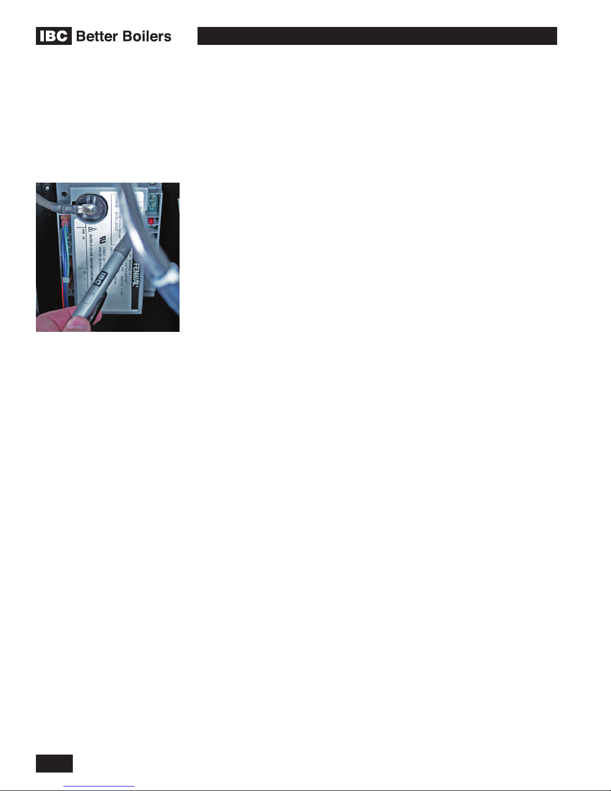
Fenwal ignition module - Microamp
(μA) test points are shown at top
right corner of module (above red
L.E.D.)
VFC 15-150, VFC 45-225 MODULATING GAS BOILERS
5.2.5 Hi-Limit Switch (water and vent)
Check resistance between leads. If resistance is very low, temperature should
be acceptable. If resistance is very high, temperature should be out of bounds.
A simple means of checking whether a high limit switch is open is by measuring
the AC voltage across the device. If the reading is 24 VAC the switch is open. If a
0VAC reading is shown, it is closed. NEVER connect an ohm-meter or continuity
checker across a live circuit.
5.2.6 Ignition Module
There are two approved ignition modules - Fenwal (grey) and Capable Controls
(white). Each have a red LED lamp providing the following signals: Fenwal – 1
rapid ash on 1st entering Pre-purge, 3 rapid ashes upon Failure to Ignite After 3
Attempts; the Capable Controls module provides a single ash at the start of each
Purge and Interpurge cycle, continuous rapid ashes during the 4 second spark
interval, solid illumination following successful ignition until burner shutdown, and
a slow on/off cycle with a 3-try failure.
Flame current can be monitored on the Fenwal. Connect an electrical test
meter - set to read Microamps (symbol μA) to the two test pins at the top right of
the ignition module. Recycle the boiler so it enters another trial for ignition and
monitor the ame current reading. When the burner ignites, a steady reading of
2-7 Microamps should be measured by your meter. The control will lock out if
the reading drops below 0.7 Microamps. (see Section 5.3.1 - “Control Module
- Maximum ignition trials error”, and Section 5.3.2 - “Ignition problems”). For
conversion from Fenwal to the Capable Control, specify IBC part# 240-049 – that
provides the module plus added wire lead and instructions.
5-4
INSTALLATION AND OPERATION INSTRUCTIONS

VFC 15-150, VFC 45-225 MODULATING GAS BOILERS
5.3 TROUBLESHOOTING GUIDE
5.3.1 Using Control Module Errors Displayed
SYMPTOM DIAGNOSIS REMEDY
AIRFLOW ERROR
Touch Screen Message:
Error – Low Air Flow
Low combustion airow; soft
error; will retry in 5 minutes
WARNING
Never attempt to repair
the control module (circuit
board). If the control module
is defective, replace it
immediately.
Check fan operation • Check lead is attached at fan.
• Cycle power off/on; listen for fan initialization.
If no action, focus your attention on the fan
itself.
Check for fouled
reference lines and air
sensor
Check achieved fan
power
Water noise in vent.
Excess condensate in
venting.
• Check clear vinyl air reference lines below
gas valve for any sign of water. After
disconnecting from black sensor, blow clear.
Check for exhaust re-ingestion, or repeated
power interruptions .
• Ensure condensate trap is not blocked.
• Go to Advanced Diagnostics and check
differential air pressure sensor (at rest and
with fan on). See Section 5.2.3.
In Diagnostics, Fan Operation, during Prepurge, Fan Pressure (FP) should move close to
Required Pressure (RP); if FP only 480 to 600
vs. RP of 1,000 to 1,200, then check for actual
vent system blockage: (a) disconnect intake
within boiler case; (b) open burner then fan/gas
valve looking for debris.
• Check condensate trap for obstructions.
Remove obstructions and rell condensate
trap with water.
• Check vent length, size and conguration,
particularly re: horizontal 2" piping.
WATERFLOW ERROR
Touch Screen Message:
Error - No Water Flow
Low water ow – soft error; will
retry in 5 minutes
TROUBLESHOOTING
Check pressure
sensors
Check for proper
piping
Check primary pump If there is a valve on the primary loop, close it
Check for restriction
in water pipe
• Check wiring: water pressure sensors to
controller.
• Check pressure sensors. See Section 5.2.4
– 2nd paragraph.
Refer to Section 1.6 Water Piping for
recommended piping installation.
and listen for cavitation (evidence ow). If not,
go to Installer Setup; select pump purge “on” to
run pumps without a heat call - check for heat
buildup at pump body (indicates no ow).
Check temperature differential across heat
exchanger at low –medium ring rate if possible.
Examine air strainer components for scale.
5-5

VFC 15-150, VFC 45-225 MODULATING GAS BOILERS
SYMPTOM DIAGNOSIS REMEDY
MAXIMUM IGNITION TRIALS
ERROR
Touch Screen Message:
Error – Ignition Failure after 3
tries
Boiler has failed to ignite on 3
successive attempts. Boiler in
lockout for 1 hour, then repeats
3-try seq. Consult service
technician if error recurs.
No spark when
igniting. Igniter
Check that igniter lead is secure at the control
module and at the probe.
probe/ame sensor
disconnected.
Manual gas shutoff is
closed or gas line not
Check for gas ow. Open manual gas shutoff
and reset boiler.
fully purged.
Gap between igniter
probe and ground
rod is too large or too
small.
Adjust gap between igniter probe/ame sensor
and ground rod to a distance of 3/16" (turn
off gas supply and remove viewport for best
visibility; use prole of 1/8" diameter ignitor rod
to gauge distance)
Spark, but no ignition. Check spark module is sending power to gas
valve – close gas supply, then disconnect
(black) electric housing from face of gas valve,
gently spread plastic tabs to open, and look for
24vac voltage between blue and brown wires
during an ignition cycle. Replace module if no
current detected
Boiler ignites, but
shuts off at the
end of the ignition
trial. Improperly
grounded pressure
vessel/burner or
unserviceable ignition
• Ensure pressure vessel is grounded.
• Check the igniter probe/ame sensor is
electrically isolated from the vessel, and its
ceramic insulator is intact.
• Replace ignition lead
• Replace spark module
lead or spark module.
HI LIMIT ERROR
Touch Screen Message:
Error – Water High-Limit
Exceeded
Water temperature exceeds hilimit. Boiler in hard lockout. Will
reset in 1 hour. Consult service
technician.
VENT HI-LIMIT ERROR
Touch Screen Message:
Error - Vent High-Limit
Exceeded *** Call for service!
Vent temperature has exceeded
the vent limit switch. Boiler
in lockout. Consult service
technician.
Defective or
disconnected hi-limit
switch.
• Check wiring to hi-limit switch and control
module.
• Check hi-limit switch. See Section 5.2.5.
• Check wiring to ensure sensor is properly
connected to control module.
• Check for evidence of any damage to vent
system.
• Push manual reset button, maintain constant
watch during boiler operation to evaluate
vent temperature at maximum operating
settings to ensure no unsafe condition exists,
e.g. max ue temp. within allowable limits for
exhaust pipe material used.
5-6
INSTALLATION AND OPERATION INSTRUCTIONS

VFC 15-150, VFC 45-225 MODULATING GAS BOILERS
SYMPTOM DIAGNOSIS REMEDY
TEMPERATURE SENSOR
ERROR
Touch Screen Message:
Error - Max. In-Out Temp.
Exceed. -> Check water ow
Water temperature signal
not within acceptable range.
Current outlet
temperature exceeds
operating limit.
Defective or
disconnected
temperature sensor.
• Check water ow.
• Check wiring to temperature sensor and
control module.
• Check temperature sensor. See Section
5.2.1.
Potential ow or sensor failure.
Consult service technician.
MISCELLANEOUS
Touch Screen Message:
• Check transformer; replace if damaged.
• Check circuit board for visible damage.
Blank – screen dark, but fan
running Indicative of powersurge damage to appliance
5.3.2 Ignition Problems
SYMPTOM DIAGNOSIS REMEDY
NOISY SPARK WHEN
IGNITING
Ignition lead is not
rmly connected.
Reconnect ignition lead.
BOILER RUMBLES WHEN
IGNITING.
BOILER WILL NOT ATTEMPT
TO IGNITE. FAN AND PUMP
ARE OPERATING NORMALLY.
BOILER WILL NOT ATTEMPT
TO IGNITE. FAN AND / OR
PUMP ARE OFF DISPLAY
NOT ILLUMINATED
Contaminants/
moisture on igniter
Ensure probe is dry by re-running post-purge;
otherwise, clean or replace igniter probe.
probe/ame sensor.
Fluctuating gas
Check CO2 level via analyzer.
pressure/ gas
pressure too high/too
low.
Check for proper
Check pressure with manometer during ignition.
piping.
No power to ignition
control module.
Igniter probe/ame
• Check system wiring.
• Check air reference tubing.
Reconnect probe.
sensor disconnected.
Blown fuse in ignition
Check fuse. If blown, replace.
module.
Defective Control
Check ignition output from control module.
Module.
No power to boiler. Check line voltage .
Defective transformer. Check transformer. Reconnect or replace as
needed.
TROUBLESHOOTING
5-7
VFC 15-150, VFC 45-225 MODULATING GAS BOILERS
5.3.3 Cycling Problems
SYMPTOM DIAGNOSIS REMEDY
RAPID CYCLING Improper values
entered via keypad.
Excess Condensate in
venting.
Obstruction in
condensate trap.
Improper vent length
or improper slope to
vent.
Incorrect settings or
defective thermostat.
Air in system or
marginal water ow.
Slow combustion air
blower.
Dirty burner/heat
exchanger.
Check load maximum temps are above target
temps, by 1/2 of the selected boiler differential.
Ensure boiler differential is OK (16-30°F is
generally adequate)
Check venting slopes on horizontal runs. Look
for sags.
Inspect and clean condensate trap.
Check venting. Compare vent length and
diameter to Table 4: Maximum Venting.
Check operation. Refer to manufacturer’s
instructions. Check setting with ammeter.
Bleed/purge system as required. Conrm
adequate pump size and temp rise in HX
Check that CO2 level is OK per Tabel 8.
Check pressure drop.
Insufcient water
Refer to recommended piping in Section 1.6
ow due to improper
piping.
Insufcient water ow
due to undersized
Check manufacturer’s rating charts/check
temperature differential across heat exchanger.
pump.
Insufcient water ow
due to restrictions in
Check temperature differential across zone/heat
exchanger.
water pipe.
Insufcient radiation. Check actual amount of radiation per zone and
refer to manufacturer’s rating tables.
Unit over-red. Clock gas meter/check gas pressure with
manometer/ check CO2 level.
Unit Oversized. Check load calculation vs. min. boiler output.
Improperly set or
Check operation with ohmmeter/voltmeter.
defective operating/
safety controls.
5-8
INSTALLATION AND OPERATION INSTRUCTIONS
VFC 15-150, VFC 45-225 MODULATING GAS BOILERS
5.3.4 Temperature Problems
SYMPTOM DIAGNOSIS REMEDY
INSUFFICIENT HEAT
Operating
Increase temperature target.
temperature too low.
Priority parameters
Review load conguration parameters.
or load conguration
improperly set up.
Unit undersized. Refer to Load Calculation vs. Boiler Output.
Air trapped within
Bleed system as required.
system.
Improper system
Refer to recommended piping in Section 1.6
piping.
System pump
undersized.
Check pump manufacturer’s data/check temp
differential across heat exchanger.
Poor gas/air mixing. Check CO2 level.
Defective thermostat. Refer to manufacturer’s instructions.
Obstruction in
Inspect and clean condensate drain.
condensate drain.
Unit cycling on
Check operation with Ohmmeter/Voltmeter.
operating/ safety
controls.
TEMPERATURE EXCEEDS
THERMOSTAT SETTING
ONE OR MORE ZONES DO
NOT HEAT PROPERLY
System radiation
undersized.
Incorrect anticipator
Check manufacturer’s rating tables for capacity
per foot.
Check with Ammeter.
setting.
Thermostat not level. Check level.
Air trapped within
Vent system/zone as required.
zone(s) piping
Insufcient radiation/
excessive heat loss.
Insufcient ow rate
Check actual length of pipe using radiation / heat
loss calculation.
Check temperature drop across zone.
to zone(s).
Defective zone valve/
Check operation per manufacturer’s instructions.
zone circulator.
TROUBLESHOOTING
5-9

VFC 15-150, VFC 45-225 MODULATING GAS BOILERS
5.3.5 Miscellaneous
SYMPTOM DIAGNOSIS REMEDY
FUMES AND HIGH HUMIDITY
Improperly installed
Refer to installation/operation instructions
condensate trap
Leak in vent piping Inspect using soap solution
BOILER STUCK ON INITIALIZE
TOUCH SCREEN MESSAGE:
Unknown Error
ERROR: WATER HIGH LIMIT /
LOW WATER CUT-OFF WON’T
CLEAR.
DHW TAKING TOO LONG TO
HEAT.
BOILER OUTPUT NOT
MODULATING UP TO
MAXIMUM DESPITE TARGET
NOT BEING REACHED.
Flue gas leak within
Visually inspect all mechanical connections
boiler
Fan board failure Replace fan.
Temperature sensor
input problem.
Test each temperature sensor for appropriate
readings and replace defective temperature
sensor.
Boiler is in 1 hour
safety lockout.
Sensor may be underreading actual water
temp.
Reset safety device and cycle boiler power off
and on to reset error.
Check sensor engagement; note well is 15cm /
almost 6 inches deep and sensor must be fully set
to back. Check programmed settings boiler temp
set too close to the required DHW temp
Possible ow issue:
check for 35 or 40
degree F temperature
Conrm that primary pump is able to overcome
head loss of boiler and primary loop piping at the
required ow rate.
difference between
boiler supply and return
water temperatures
(evokes electronic
fence).
PRIMARY PUMP RUNS
DURING PARALLEL-PIPED
DHW CALL.
Load denition as DHW. On Touch Screen Controllers set the boiler pump
to off in the Installer Set-up Menu.
5-10
INSTALLATION AND OPERATION INSTRUCTIONS

VFC 15-150, VFC 45-225 MODULATING GAS BOILERS
6.0
DIAGRAMS
6.1 - VFC 15-150 PARTS DIAGRAMS
6.2 - VFC 45-225 PARTS DIAGRAMS
6.3 - ADDITIONAL PARTS DIAGRAMS
6.4 - WIRING DIAGRAMS
6.5 - SEQUENCE OF OPERATION
DIAGRAMS
6-1

VFC 15-150, VFC 45-225 MODULATING GAS BOILERS
6.1 VFC 15-150 PARTS DIAGRAM
Diagram 6.1-1: Boiler Assembly – VFC 15-150
6-2
INSTALLATION AND OPERATION INSTRUCTIONS

VFC 15-150, VFC 45-225 MODULATING GAS BOILERS
ITEM# DESCRIPTION PART# QTY
6 FAN, RG130 240-040 1
11 GASKET, FAN - FAN ADAPTER 250-310 1
15 FAN ADAPTER PLATE 180-023 1
20 SCREW, M4 x 10, FLAT HEAD,
3
EQUIPPED w/240-040
25 AIR INTAKE, BASE 180-017 1
30 SWIRL PLATE 180-020 1
35 AIR INTAKE, COVER 180-018 1
40 GAS VALVE 180-022 1
45 SPACER, #8, 1/8” THICK, 1/4”
150-092 3
O.D.
50 SCREW, M4 x 30, TAPPING,
3
EQUIPPED w/180-022
55 SCREW, #10-32 x 7/8”, HEX
150-110 4
HEAD
61 GASKET, FAN - FAN
250-311 1
COUPLER
70 NUT, #10-32, w/EXTERNAL
150-111 4
TOOTH WASHER
75 SWITCH, SNAP DISK,
240-030 1
MANUAL RESET, 230F
80 SWITCH, SNAP DISK, AUTO-
240-032 1
RESET, 203F
85 MOUNTING PLATE, SNAP
250-333 1
DISK
90 IGNITION MODULE
240-004C 1
(ALTERNATE CAPABLE
CONTROLS 240-049)
95 SCREW, SHEET METAL, #8
150-021 2
x 3/4”
100 SENSOR, WATER PRESSURE 240-006 2
105 ENCLOSURE 250-312 1
111 GAS VALVE MOUNTING
250-314 1
BRACKET
115 SENSOR, AIR PRESSURE 240-003 1
120 TRANSFORMER 240-008 1
125 SIDE COVER, CONTROLLER 250-327 1
130 SCREW, #6-32 x 3/8”, PAN
150-014 6
HEAD
135 CHASSIS, CONTROLLER PCB 250-583 1
140 PCB, CONTROLLER V10.0 230-002 1
145 SPACER, MALE - FEMALE,
150-096 4
#6-32 x 3/4”
150 FRONT COVER,
250-591 1
CONTROLLER
155 PIPE CLAMP 150-039 3
160 2” ABS AIR INTAKE
1
ASSEMBLY
165 CLIP NUT, M10, 19mm
150-105 4
CENTER
170 HEAT EXCHANGER 170-009 1
ITEM# DESCRIPTION PART# QTY
175 REFRACTORY, OUTER 250-287 1
180 REFRACTORY, INNER 250-306 1
185 GASKET, HEAT EXCHANGER
250-328 1
LID
190 LID, HEAT EXCHANGER 250-284 1
195 SCREW, M10 x 55, HEX HEAD 150-106 4
200 WASHER, FENDER, M10 150-104 4
205 IGNITOR 240-002 1
210 GASKET, IGNITOR 250-050 1
215 SCREW, M4 x 10, PAN HEAD 150-013 4
220 SIGHT GLASS HOLDER 250-309 1
225 GASKET, SIGHT GLASS 250-060 2
230 SIGHT GLASS 250-059 1
235 GASKET, BURNER 250-308 2
240 BURNER 180-021 1
245 V-CLAMP 150-071 1
250 FAN COUPLER 250-280 1
270 FRONT COVER, VFC 150 250-313 1
Diagram 6.1-1 (Parts List)
Diagram 6.1-2: Door Assembly – VFC 15-150
DIAGRAMS
6-3

VFC 15-150, VFC 45-225 MODULATING GAS BOILERS
6.2 VFC 45-225 PARTS DIAGRAM
Diagram 6.2-1: Boiler Assembly – VFC 45-225
6-4
INSTALLATION AND OPERATION INSTRUCTIONS

VFC 15-150, VFC 45-225 MODULATING GAS BOILERS
ITEM# DESCRIPTION PART# QTY
5 FAN, NRG 137 240-048 1
10 O-RING 150-073 1
15 FAN ADAPTER PLATE 180-023 1
20
SCREW, M4x10 TAPPING,
3
FLAT HEAD, EQUIPPED w/FAN
25 AIR INTAKE, BASE 180-017 1
30 SWIRL PLATE 180-020 1
35 AIR INTAKE, COVER 180-018 1
40 GAS VALVE 180-022 1
45 SPACER, #8, 1/8” THICK, 1/4”
150-092 3
O.D.
50 SCREW, M4 x 30, TAPPING,
3
EQUIPPED w/GAS VALVE
55 SCREW #10-32 x 7/8” HEX
150-110 4
HEAD
60 GASKET, FAN - FAN
250-381 2
COUPLER
65 FAN COUPLER SPACER 250-370 1
70 NUT, #10-32, w/EXTERNAL
150-111 4
TOOTH WASHER
75 SWITCH, SNAP DISK,
240-030 1
MANUAL RESET, 230F
80 SWITCH, SNAP DISK, AUTO-
240-032 1
RESET, 203F
85 MOUNTING PLATE, SNAP
250-333 1
DISK
90 IGNITION MODULE
240-004C 1
(ALTERNATE CAPABLE
CONTROLS 240-049)
95 SCREW, SHEET METAL, #8
150-021 2
x 3/4”
100 SENSOR, WATER PRESSURE 240-006 2
105 ENCLOSURE 250-312 1
110 MOUNTING BRACKET, GAS
250-316 1
VALV E
115 SENSOR, AIR PRESSURE 240-003 1
120 TRANSFORMER 240-008 1
125 SIDE COVER, CONTROLLER 250-327 1
130 SCREW, #6-32 x 3/8” 150-014 6
135 CHASSIS, CONTROLLER PCB 250-583 1
140 PCB, CONTROLLER V10.0 230-002 1
145 SPACER, MALE - FEMALE,
150-096 4
#6-32 x 3/4”
150 FRONT COVER,
250-591 1
CONTROLLER
155 PIPE CLAMP 150-039 3
160 2” ABS AIR INTAKE
1
ASSEMBLY
165 CLIP NUT, M10, 19mm
150-105 4
CENTER
170 HEAT EXCHANGER 170-009 1
ITEM# DESCRIPTION PART# QTY
175 REFRACTORY, OUTER 250-287 1
180 REFRACTORY, INNER 250-306 1
185 GASKET, HEAT EXCHANGER
250-328 1
LID
190 LID, HEAT EXCHANGER 250-284 1
195 SCREW, M10 x 55, HEX HEAD 150-106 4
200 WASHER, FENDER, M10 150-104 4
205 IGNITOR 240-002 1
210 GASKET, IGNITOR 250-050 1
215 SCREW, M4 x 10, PAN HEAD 150-013 4
220 SIGHT GLASS HOLDER 250-309 1
225 GASKET, SIGHT GLASS 250-060 2
230 SIGHT GLASS 250-059 1
235 GASKET, BURNER 250-308 2
240 BURNER 180-021 1
245 V-CLAMP 150-071 1
250 FAN COUPLER 250-280 1
280 FRONT COVER, VFC 225 250-315 1
Diagram 6.2-1 (Parts List)
Diagram 6.2-2: Door Assembly – VFC 45-225
DIAGRAMS
6-5

Diagram 6.3-1: Vent high limit
VFC 15-150, VFC 45-225 MODULATING GAS BOILERS
6.3 ADDITIONAL PARTS DIAGRAMS
51 TRAP/EXHAUST KIT
Diagram 6.3-2: Intake Air Filter (order separately)
Diagram 6.3-4: Accessory parts kit (shipped with boiler)
ITEM # DESCRIPTION PART #
47 Pressure Relief Valve 180-005
49 Outdoor Temperature Sensor 240-025
51(a) Trap/Exhaust Kit VFC15-150 P-150
51(b) Trap/Exhaust Kit VFC45-225 P-151
66 Washer, #10, External Tooth 150-085
67 Screw, #10-32 x 1/2" 150-084
75 Switch, Snap disk, Manual Reset, 230F 240-030
100 Sensor, Water Pressure 240-006
101 Pressure Sensor Bushing 250-023
103 Intake Air Filter Element 180-103
104 Intake Air Filter Housing 180-104
PARTS BELOW - NOT SHOWN
68 Ignition Cable 210-001
69 Fuse Kit (10 pack) P-114
71 8 Position Terminal Block - Green 240-019
72 22 Position Terminal Block - Orange 240-020
73 DC to AC Fan Harness Conversion Kit 71-ACDC
74 Acid Neutralization Tank 180-029
102 Ignitor Kit w/Gasket P-142
Diagram 6.3-3: Water pressure sensor group
6-6
INSTALLATION AND OPERATION INSTRUCTIONS
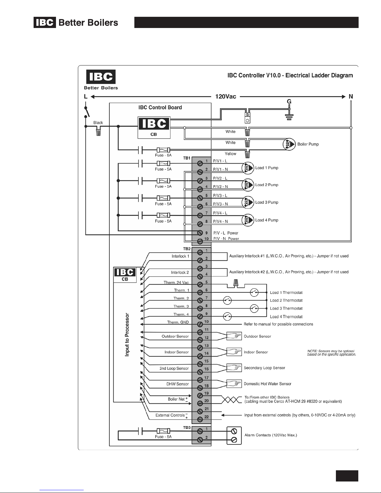
VFC 15-150, VFC 45-225 MODULATING GAS BOILERS
6.4 WIRING DIAGRAMS
Diagram 6.4-1: Ladder wiring diagram
DIAGRAMS
6-7

VFC 15-150, VFC 45-225 MODULATING GAS BOILERS
Diagram 6.4-2: Internal wiring diagram
6-8
INSTALLATION AND OPERATION INSTRUCTIONS

VFC 15-150, VFC 45-225 MODULATING GAS BOILERS
6.5 SEQUENCE OF OPERATION
Diagram 6.5-1: Sequence of operation diagram
DIAGRAMS
6-9

INSTALLATION & COMMISSIONING REPORT
Boiler Details:
Model Number _____________________ Serial Number ______________________________________________
Date of Installation ______________ Address of installation __________________________________________
_____________________________________________________________________________________________
User contact information _______________________________________________________________________
Installer Information Company ___________________________________________________________________
Address ______________________________________________________________________________________
Phone/Fax/E mail ____________________________________________________________________________
__
Fuel Natural Gas Propane
Gas Supply Pressure (high re) _______ Inches w.c. Measured Rate of Input (high re) ____________ Btu/hr
Installation instructions have been followed and completed (Section 1 of Installation and Operating Instructions).
Check-out procedures have been followed and completed (Section 3 of Installation and Operating Instructions).
Leak testing completed gas piping venting system Fan and combustion components
System Cleaned and Flushed (type of cleaner used) ________________________________________________
System Filled (type/concentration of any glycol/chemicals used) _______________________________________
Air purge completed
Relief Valve correctly installed and piped Relief valve “try lever” test performed
Condensate trap lled
Ignition Safety Shutoff test completed. Flame current reading - High re _______ µA - Low re _______ µA
Owner advised and instructed in the safe operation and maintenance of the boiler and system.
Information regarding the unit and installation received and left with owner
Condensate drain clear and free owing Condensate Neutralization? Yes/No
Combustion Readings:
CO
_____________ % O2 ______________ % CO ____________ ppm
2
Flue temperature _________ Return water temperature (measure simultaneously with ue temp.) _______________
Installers: send this completed sheet - Fax to 604 877 0295 - or - scan and Email to info@ibcboiler.com, and earn
an extra year’s Parts Warranty coverage (User to submit corresponding Installation Record from User Guide).
Commissioning has been completed as listed on this report - Installer Signature _____________________________

INSTALLER SET-UP
Load Denition - Load #1 _______________________________________________________________________
Load Conguration - Load #1
_____________________________________________________________________________________________
Load Denition - Load #2 _______________________________________________________________________
Load Conguration - Load #2
_____________________________________________________________________________________________
Load Denition - Load #3 _______________________________________________________________________
Load Conguration - Load #3
_____________________________________________________________________________________________
Load Denition - Load #4 _______________________________________________________________________
Load Conguration - Load #4
_____________________________________________________________________________________________

SERVICE RECORD
DATE LICENSED CONTRACTOR DESCRIPTION OF WORK DONE

NOTES

NOTES

NOTES

IMPORTANT
This Boiler is equipped with a feature that saves energy by reducing the boiler water
temperature as the heating load decreases. This feature is equipped with an override
which is provided primarily to permit the use of an external energy management system
that serves the same function. THIS OVERRIDE MUST NOT BE USED UNLESS AT
LEAST ONE OF THE FOLLOWING CONDITIONS IS TRUE:
• An external energy management system is installed that reduces the boiler
water temperature as the heating load decreases.
• This boiler is not used for any space heating.
• This boiler is part of a modular or multiple boiler system having a total input
of 300,000 BTU/hr or greater.
• This boiler is equipped with a tankless coil (not applicable to IBC’s VFC boilers).
US installers should contact IBC for any further information required.

REVISION HISTORY
R1 (SEPTEMBER 2005) Initial release
R2 (JULY 2007) Venting requirements (Canada) to ULC-S636; internal wiring diagram and warranty
details added
R3 (MARCH 2010) VFC 45-225-SL variant added (with new NRG-137 fan); warranty removed to
separate document
R4 (SEPTEMBER 2012) Polypropylene venting, detachable lid heat exchanger and US Energy Act disclosures
added; VFC 45-225-SL designation merged within base VFC 45-225 model
R5 (SEPTEMBER 2014) Disclosures updated to CSA 4.9-2014 / ANSI Z21.13-2014 Standard; Touch Screen
Controller added
R6 (MAY 2015) Address update

IBC Technologies Inc.
8015 North Fraser Way
Burnaby, BC
Canada V5J 5M8
Tel: 604.877.0277
Fax: 604.877.0295
www.ibcboiler.com
120-100E-A-R6
May 2015
© IBC Technologies Inc. 2015
 Loading...