


IOPS-302
Open Pluggable Specification
Digital Signage Player
User’s Manual
Version 1.0
(May 2018)

ii
IOPS-302 User Manual
Copyright
© 2018 IBASE Technology, Inc. All rights reserved.
No part of this publication may be reproduced, copied, stored in a retrieval system, translated
into any language or transmitted in any form or by any means, electronic, mechanical,
photocopying, or otherwise, without the prior written consent of IBASE Technology, Inc.
(hereinafter referred to as “IBASE”).
Disclaimer
IBASE reserves the right to make changes and improvements to the products described in
this document without prior notice. Every effort has been made to ensure the information in
the document is correct; however, IBASE does not guarantee this document is error-free.
IBASE assumes no liability for incidental or consequential damages arising from misuse or
inability to use the product or the information contained herein, and for any infringements of
rights of third parties, which may result from its use.
Trademarks
All the trademarks, registrations and brands mentioned herein are used for identification
purposes only and may be trademarks and/or registered trademarks of their respective
owners.

IOPS-302 User Manual
iii
Compliance
The product described in this manual complies with all applicable European Union
(CE) directives if it has a CE marking. For systems to remain CE compliant, only CEcompliant parts may be used. Maintaining CE compliance also requires proper cable
and cabling techniques.
This product has been tested and found to comply with the limits for a Class B
device, pursuant to Part 15 of the FCC Rules. These limits are designed to provide
reasonable protection against harmful interference in a residential installation. This
equipment generates, uses and can radiate radio frequency energy and, if not
installed and used in accordance with manufacturer’s instructions, may cause
harmful interference to radio communications.
WEEE
This product must not be disposed of as normal household waste, in
accordance with the EU directive of for waste electrical and electronic
equipment (WEEE - 2012/19/EU). Instead, it should be disposed of by
returning it to a municipal recycling collection point. Check local
regulations for disposal of electronic products.
Green IBASE
This product complies with the current RoHS directives restricting the
use of the following substances in concentrations not to exceed 0.1%
by weight (1000 ppm) except for cadmium, limited to 0.01% by weight
(100 ppm).
• Lead (Pb)
• Mercury (Hg)
• Cadmium (Cd)
• Hexavalent chromium (Cr6+)
• Polybrominated biphenyls (PBB)
• Polybrominated diphenyl ether (PBDE)

iv
IOPS-302 User Manual
Important Safety Information
Carefully read the following safety information before using this device.
Setting up your system:
• Put the device horizontally on a stable and solid surface.
• Do not use this product near water or any heated source.
• Leave plenty of space around the device and do not block the ventilation
openings. Never drop or insert any objects of any kind into the openings.
• Use this product in environments with ambient temperatures between 0˚C and
45˚C.
Care during use:
• Do not place heavy objects on the top of the device.
• Make sure to connect the correct voltage to the device. Failure to supply the
correct voltage could damage the unit.
• Do not walk on the power cord or allow anything to rest on it.
• If you use an extension cord, make sure the total ampere rating of all devices
plugged into the extension cord does not cord’s ampere rating.
• Do not spill water or any other liquids on your device.
• Always unplug the power cord from the wall outlet before cleaning the device.
• Only use neutral cleaning agents to clean the device.
• Vacuum dust and particles from the vents by using a computer vacuum cleaner.
Product Disassembly
Do not try to repair, disassemble, or make modifications to the device. Doing so will
void the warranty and may result in damage to the product or personal injury.
CAUTION
Replace only with the same or equivalent type recommended by the manufacturer.
Dispose of used batteries by observing local regulations.

IOPS-302 User Manual
v
Warranty Policy
• IBASE standard products:
24-month (2-year) warranty from the date of shipment. If the date of shipment
cannot be ascertained, the product serial numbers can be used to determine
the approximate shipping date.
• 3rd-party parts:
12-month (1-year) warranty from delivery for 3rd-party parts that are not
manufactured by IBASE, such as CPU, CPU cooler, memory, storage devices,
power adaptor, display panel and touch screen.
* PRODUCTS, HOWEVER, THAT FAIL DUE TO MISUSE, ACCIDENT,
IMPROPER INSTALLATION OR UNAUTHORIZED REPAIR SHALL BE
TREATED AS OUT OF WARRANTY AND CUSTOMERS SHALL BE BILLED
FOR REPAIR AND SHIPPING CHARGES.
Technical Support & Services
1. Visit the IBASE website at www.ibase.com.tw to find the latest information about
the product.
2. If you encounter any technical problems and require assistance from your
distributor or sales representative, please prepare and send the following
information:
• Product model name
• Product serial number
• Detailed description of the problem
• Error messages in text or screenshots if any
• The arrangement of the peripherals
• Software used (such as OS and application software)
3. If repair service is required, please download the RMA form at
http://www.ibase.com.tw/english/Supports/RMAService/.
Fill out the form and contact your distributor or sales representative.

vi
IOPS-302 User Manual
Table of Contents
Compliance.................................................................................................... iii
Important Safety Information ....................................................................... iv
CAUTION ....................................................................................................... iv
Warranty Policy .............................................................................................. v
Technical Support & Services ...................................................................... v
Chapter 1 General Information ................................................................ 1
1.1 Introduction ............................................................................................. 2
1.2 Features .................................................................................................. 2
1.3 Packing List ............................................................................................ 2
1.4 Optional Accessories .............................................................................. 2
1.5 Specifications .......................................................................................... 3
1.6 Overview ................................................................................................. 4
1.7 Dimensions ............................................................................................. 5
Chapter 2 Hardware Configuration ......................................................... 6
2.1 Installations ............................................................................................. 7
2.1.1 Memory Module Installation ...................................................... 7
2.1.2 M.2 Cards Installation ............................................................... 8
2.1.3 WiFi / 3G / 4G Antenna Installation ........................................... 8
2.2 Pin Assignment for COM RS-232 Port .................................................... 9
2.3 Setting the Jumpers .............................................................................. 10
2.3.1 How to Set Jumpers ............................................................... 10
2.4 Jumper & Connector Locations on Motherboard ................................... 11
2.5 Jumper & Connectors Quick Reference ................................................ 13
2.5.1 ATX & AT Mode Selection (JP1) .......................................... 14
2.5.2 Clearing CMOS Data (JP2) .................................................. 14
2.5.3 System Fan Power Connector (SYS_FAN1) ........................ 15
Chapter 3 Driver Installation ................................................................. 16
3.1 Introduction ........................................................................................... 17
3.2 AMD Merlin Falcon Graphics Driver Installation .................................... 17
3.3 HD Audio Driver Installation .................................................................. 18
3.4 LAN Driver Installation .......................................................................... 19

IOPS-302 User Manual
vii
Chapter 4 BIOS Setup ............................................................................ 20
4.1 Introduction ........................................................................................... 21
4.2 BIOS Setup ........................................................................................... 21
4.3 Main Settings ........................................................................................ 22
4.4 Advanced Settings ................................................................................ 23
4.4.1 ACPI Settings ......................................................................... 23
4.4.2 IDE Configuration ................................................................... 24
4.4.3 F81846 Super IO Configuration .............................................. 24
4.4.4 Hardware Monitor ................................................................... 27
4.4.5 CPU Configuration .................................................................. 28
4.4.6 CSM Configuration ................................................................ . 29
4.4.7 USB Configuration .................................................................. 30
4.5 Chipset Settings .................................................................................... 31
4.5.1 SB SATA Configuration .......................................................... 31
4.5.2 North Bridge ........................................................................... 32
4.6 Security Settings ................................................................................... 33
4.7 Boot Settings......................................................................................... 34
4.8 Save & Exit Settings.............................................................................. 35
Appendix ...................................................................................................... 36
A. I/O Port Address Map ............................................................................ 37
B. Interrupt Request Lines (IRQ) ............................................................... 40
C. Watchdog Timer Configuration .............................................................. 41

1
Chapter 1
General Information
The information provided in this chapter includes:
• Features
• Packing List
• Specifications
• Optional Accessories
• Overview
• Dimensions

2
IOPS-302 User Manual
1.1 Introduction
The IOPS-302 is a slot-in digital signage player compliant with OPS (Open
Pluggable Specification). It is powered by AMD 3rd Generation R & G series
processors, supports HDMI high definition video playback, and provides
outstanding performance. It is fully compatible with large format OPS displays
and monitors and allows cableless deployment and easy maintenance.
1.2 Features
• Supports 3
rd
Gen. AMD Embedded R & G series APU.
• 1 or 2 x DDR4-2133 SO-DIMM, expandable to 32GB
• HDMI display output and audio jacks for line-out and Mic-in
• 1 x RJ45 for GbE LAN, 1 x RJ50 for RS-232 serial COM port
• 2 x USB 3.0 ports, 2 x USB 2.0 ports
• 1 x M.2 E2230 for Wi-Fi or Bluetooth options
1.3 Packing List
Your product package should include the items listed below. If any of the
items below is missing, contact the distributor or the dealer from whom you
have purchased the product. Drivers and this user manual are downloadable
from our website.
• IOPS-302 OPS Digital Signage Player
1.4 Optional Accessories
IBASE provides optional accessories as listed below. Please contact us or
your dealer if you would like to order any item(s).
• IOPS-DK1-SYS docking kit with two screws
• Power adaptor & power cord

General Information
IOPS-302 User Manual
3
1
1.5 Specifications
Product
IOPS-302 / IOPS-302-N224
System
Mainboard
OPS302
Operating
System
• Windows 10 IoT Enterprise (64-bit)
• Windows 10 (64-bit), 8.1 (64-bit) & 7 (32-bit / 64-bit)
• Windows Embedded Standard 8 (32-bit / 64-bit) &
Windows 7 (32-bit / 64-bit)
• Linux Open Source (64-bit)
CPU
AMD R & G -Series 28 nm QC / DC APU
FP4 BGA package, 37 x 29 mm, 0.8 mm pitch
Chipset
AMD integrated SoC
Memory
IOPS-302: 2 x DDR4-2133 SO-DIMM, dual channel, Max. 32GB
IOPS-302-N224: 1 x DDR4-2133 SO-DIMM, single channel, Max.
16GB
Graphics
Next-gen. AMD Radeon™ HD GPU integrated
Network
Controller
Realtek RTL8111G Gigabit LAN controller
Super I/O
Fintek F81846AD
Storage
1 x M.2 M2280 slot for SATA SSD
Power
Requirement
12V ~ 19V DC-in (Intel® OPS standard)
Watchdog
Watchdog Timer 256 segments, 0, 1, 2…255 sec/min
Chassis
SGCC, black & gray
Mounting
OPS standard bracket
Dimensions
(W x H x D)
200 x 30 x 119 mm (7.87” x 1.18” x 4.69”)
Net Weight
0.9 kg (1.98 lb)
Compliance
CE, FCC class B
I/O Ports
HDMI
1 x HDMI 1.4b
LAN
1 x GbE RJ45 LAN port
Serial
1 x RJ50 for COM1 RS-232 port
USB
• 2 x USB 3.0
• 2 x USB 2.0

4
IOPS-302 User Manual
Audio Jack
• 1 x Line-Out
• 1 x Mic-In
Expansion
1 x M.2 E2230 for WiFi or BT options
Environment
Temperature
• Operating: 0 ~ 45 °C (32 ~ 113 °F)
• Storage: -20 ~ 80 °C (-4 ~ 176 °F)
Relative
Humidity
5 ~ 90% at 45°C (non-condensing)
Vibration
SSD: 5 grms / 5~500Hz / random operation
All specifications are subject to change without prior notice.
1.6 Overview
No.
Name
No.
Name
1
Screw Holes
(for the optional docking kit)
6
RJ50 COM RS-232 Port
2
HDMI Port
7
Audio Jacks
(From left to right: Line-Out, Mic-In)
3
GbE LAN Port
8
Antenna Holes
4
USB 3.0
9
Power Button
5
USB 2.0
10
LED Indicators
(From left to right: for power, for HDD)

General Information
IOPS-302 User Manual
5
1
1.7 Dimensions
Unit: mm

6
Chapter 2
Hardware Configuration
This section contains general information about:
• Installations
• Jumper and connectors

Hardware Configuration
IOPS-302 User Manual
7
2
2.1 Installations
Before installing any card or module into the device, remove the screws
shown in the picture below to pull out the cover.
2.1.1 Memory Module Installation
To install or replace the memory modules, locate the memory slot on the
board and perform the following steps:
1. Align the key of the memory module with that on the memory slot and
insert the module slantwise.
2. Gently push the module in an upright position until the clips of the slot
close to hold the module in place when the module touches the bottom of
the slot.
To remove a module, use your fingers to press the clips outwards until the
module pops up. Grab the module gently and pull it out of the slot.

8
IOPS-302 User Manual
2.1.2 M.2 Cards Installation
1. Align the bus connector of the M.2 card with that of the M.2 slot, and insert
the card slantwise.
2. Push the M.2 card downwards as shown in the picture below, and fix it
with a screw.
2.1.3 WiFi / 3G / 4G Antenna Installation
Insert the WiFi / 3G / 4G antenna extension cable through the antenna hole of
the front I/O cover and fasten the antenna as shown below. Then apply
adhesive around the hex nut behind the front I/O cover to prevent the
extension cable from falling off if the cable becomes loose.
1. Fasten the hex nut and the washer. Then
install the antenna.
2. Apply adhesive around here.
Info: The diameter of the nut is around 6.35 mm (0.25”-36UNC).

Hardware Configuration
IOPS-302 User Manual
9
2
2.2 Pin Assignment for COM RS-232 Port
(RJ50 connector)
Pin
Signal Name
Pin
Signal Name
1
DSR (Data set ready)
6
DCD (Data carrier detect)
2
Ground
7
DTR (Data terminal ready)
3
Ground
8
CTS (Clear to send)
4
TX (Transmit)
9
RTS (Request to send)
5
RX (Receive)
10
RI (Ring indicator)
101

10
IOPS-302 User Manual
2.3 Setting the Jumpers
Configure your device by using jumpers to enable the features that you need
based on your applications. Contact your supplier if you have doubts about
the best configuration for your use.
2.3.1 How to Set Jumpers
Jumpers are short-length conductors consisting of several metal pins with a
base mounted on the circuit board. Jumper caps are placed (or removed) on
the pins to enable or disable functions or features. If a jumper has 3 pins, you
can connect Pin 1 with Pin 2 or Pin 2 with Pin 3 by shorting the jumper.
A 3-pin jumper
A jumper cap
Refer to the illustration below to set jumpers.
Pin closed
Oblique view
Illustration in the manual
Open
1-2
2-3
When two pins of a jumper are encased in a jumper cap, this jumper is
closed, i.e. turned On.
When a jumper cap is removed from two jumper pins, this jumper is open, i.e.
turned Off.
Pin# 1
2
3
1 2 3
1 2 3
1 2 3

Hardware Configuration
IOPS-302 User Manual
11
2
2.4 Jumper & Connector Locations on Motherboard
Motherboard: OPS302
OPS302 – top view

12
IOPS-302 User Manual
OPS302 – bottom view

Hardware Configuration
IOPS-302 User Manual
13
2
2.5 Jumper & Connectors Quick Reference
Jumper:
Function
Connector Name
Page
ATX & AT Mode Selection
JP1
14
Clearing CMOS Data
JP2
14
Connectors:
Function
Connector Name
Page
System Fan Connector
SYS_FAN1
15
Power Button
SW1
--
OPS Connector
CN1
--
HDMI Port
CN2
--
GbE LAN Port
CN3
--
Dual USB 3.0 Port
CN4
--
Dual USB 2.0 Port
CN5
--
COM RS-232 Port
[1]
CN6
--
Audio Jack
CN7, CN8
--
DDR4 Memory Slot
J3, J6
--
M.2 E2230 Slot
J2
--
M.2 M2280 Slot
J7
--
LED Indicator
LED1 (for power),
LED2 (for HDD)
-Battery Socket
BAT1
--
Factory Use Only
J1, J4, J5
--
[1]: Refer to 2.2 Pin Assignment for COM RS-232 Port.
14
IOPS-302 User Manual
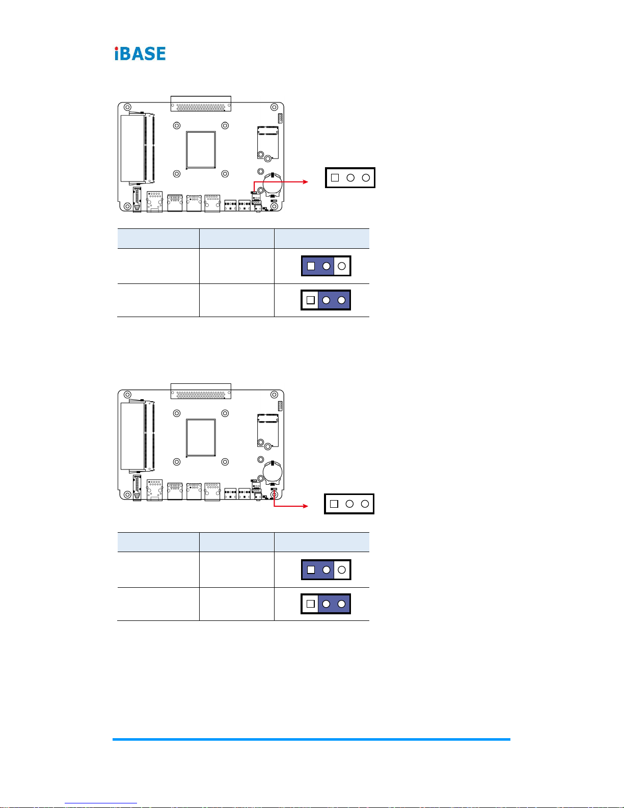
2.5.1 ATX & AT Mode Selection (JP1)
,,
Function
Pin closed
Illustration
ATX Mode
(default)
1-2
AT Mode
2-3
2.5.2 Clearing CMOS Data (JP2)
Function
Pin closed
Illustration
Normal
(default)
1-2
Clear CMOS
2-3
1
1
1
1
1
1

Hardware Configuration
IOPS-302 User Manual
15
2
2.5.3 System Fan Power Connector (SYS_FAN1)
Pin
Signal Name
Pin
Signal Name
1
Ground
3
Rotation detection
2
+12V
1

16
Chapter 3
Driver Installation
The information provided in this chapter includes:
• AMD Merlin Falcon Graphics Drivers
• HD Audio Drivers
• LAN Network Drivers

Driver Installation
IOPS-302 User Manual
17
3
3.1 Introduction
This section describes the installation procedures for software drivers. The
software drivers are available on IBASE website www.ibase.com.tw. Register
as a member on our website to download all the necessary drivers.
3.2 AMD Merlin Falcon Graphics Driver Installation
1. Run the Setup.exe file to start the installer.
2. Tick the desired items and click Install.
3. When the installation is complete, restart the system for changes to take
effect.

18
IOPS-302 User Manual
3.3 HD Audio Driver Installation
1. Run the Setup.exe file and the wizard will start.
2. On the Welcome screen of the InstallShield Wizard, click Next to start
installing the audio driver on your system.
3. When installation is complete, restart the system for changes to take
effect.

Driver Installation
IOPS-302 User Manual
19
3
3.4 LAN Driver Installation
1. Run the Setup.exe file.
2. On the Welcome screen of the InstallShield Wizard, click Next to continue.
3. Click Install.
4. Installation is now complete. Restart the system for changes to take effect.

20
Chapter 4
BIOS Setup
This chapter describes the different settings available in the AMI
BIOS that comes with the board. The topics covered in this chapter
are as follows:
• Main Settings
• Advanced Settings
• Chipset Settings
• Security Settings
• Boot Settings
• Save & Exit

BIOS Setup
IOPS-302 User Manual
21
4
4.1 Introduction
The BIOS (Basic Input/Output System) installed in the ROM of your computer
system supports Intel® processors. The BIOS provides critical low-level
support for standard devices such as disk drives, serial ports and parallel
ports. It also provides password protection as well as special support for
detailed fine-tuning of the chipset controlling the entire system.
4.2 BIOS Setup
The BIOS provides a Setup utility program for specifying the system
configurations and settings. The BIOS ROM of the system stores the Setup
utility. When you turn on the computer, the BIOS is immediately activated.
Press the <Del> key immediately allows you to enter the Setup utility. If you
are a little bit late pressing the <Del> key, POST (Power On Self Test) will
continue with its test routines, thus preventing you from invoking the Setup.
If you still need to enter Setup, restart the system by pressing the ”Reset”
button or simultaneously pressing the <Ctrl>, <Alt> and <Delete> keys.
You can also restart by turning the system Off and back On again.
The following message will appear on the screen:
Press <DEL> to Enter Setup
In general, press the arrow keys to highlight items, <Enter> to select, the
<PgUp> and <PgDn> keys to change entries, <F1> for help, and <Esc> to
quit.
When you enter the BIOS Setup utility, the Main Menu screen will appear on
the screen. The Main Menu allows you to select from various setup functions
and exit choices.
Warning: It is strongly recommended that you avoid making any changes to
the chipset defaults.
These defaults have been carefully chosen by both AMI and your
system manufacturer to provide the absolute maximum
performance and reliability. Changing the defaults could make the
system unstable and crash in some cases.

22
IOPS-302 User Manual
4.3 Main Settings
BIOS Setting
Description
System Date
Sets the date.
Use the <Tab> key to switch between the data
elements.
System Time
Set the time.
Use the <Tab> key to switch between the data
elements.

BIOS Setup
IOPS-302 User Manual
23
4
4.4 Advanced Settings
This section allows you to configure, improve your system and allows you to
set up some system features according to your preference.
4.4.1 ACPI Settings
BIOS Setting
Description
Enable Hibernation
Enables / Disables System ability to hibernate
(OS/S4 Sleep State). This option may be not
effective with some OS.
ACPI Sleep State
Selects the highest SCPI sleep state the
system will enter when the SUSPEND button is
pressed.
Options: Suspend Disabled, S3 (Suspend to
RAM)

24
IOPS-302 User Manual
4.4.2 IDE Configuration
4.4.3 F81846 Super IO Configuration
BIOS Setting
Description
Serial Port Configuration
Sets parameters of Serial Ports (COMA).
Enables / Disables the serial port and select
an optimal setting for the Super IO device.
Power Failure
Options: Always on, Always off

BIOS Setup
IOPS-302 User Manual
25
4
4.4.3.1. Serial Port 1 Configuration
BIOS Setting
Description
Serial Port
Sets parameters of Serial Ports (COM).
Change Settings
Selects an optimal settings for Super I/O
device.
Options:
• Auto
• IO = 3F8h; IRQ = 4
• IO = 3F8h; IRQ = 3, 4, 5, 6, 7, 9, 10, 11, 12
• IO = 2F8h; IRQ = 3, 4, 5, 6, 7, 9, 10, 11, 12
• IO = 3E8h; IRQ = 3, 4, 5, 6, 7, 9, 10, 11, 12
• IO = 2E8h; IRQ = 3, 4, 5, 6, 7, 9, 10, 11, 12

26
IOPS-302 User Manual
4.4.3.2. Serial Port 2 Configuration
BIOS Setting
Description
Serial Port
Sets parameters of Serial Ports (COMA).
Change Settings
Selects an optimal settings for Super I/O
device.
Options:
• Auto
• IO = 2F8h; IRQ = 3
• IO = 3F8h; IRQ = 3, 4, 5, 6, 7, 9, 10, 11, 12
• IO = 2F8h; IRQ = 3, 4, 5, 6, 7, 9, 10, 11, 12
• IO = 3E8h; IRQ = 3, 4, 5, 6, 7, 9, 10, 11, 12
• IO = 2E8h; IRQ = 3, 4, 5, 6, 7, 9, 10, 11, 12

BIOS Setup
IOPS-302 User Manual
27
4
4.4.4 Hardware Monitor
BIOS Setting
Description
CPU Fan Smart Fan
Control
Disables or selects a temperature threshold.
Options: Disabled, 50°C, 60°C, 70°C, 80°C
Temperatures / Voltages
These fields are the parameters of the
hardware monitoring function feature of the
motherboard. The values are read-only values
as monitored by the system and show the PC
health status.
CPU Shutdown
Temperature
This field enables or disables the Shutdown
Temperature
Options: Disabled, 70°C, 75°C, 80°C, 85°C,
90°C, 95°C

28
IOPS-302 User Manual
4.4.5 CPU Configuration
BIOS Setting
Description
Node 0 Information
When the function is enabled,a VMM can
utilize the additional hardware capabilities
provided by Vanderpool Technology.

BIOS Setup
IOPS-302 User Manual
29
4
4.4.6 CSM Configuration
BIOS Setting
Description
CSM Support
Enables or disables CSM support.
GateA20 Active
• Upon Request disables GA20 when using BIOS
services.
• Always cannot disable GA20, but is useful when
any RT code is executed above 1 MB.
Option ROM
Messages
Sets the display mode for Option ROM.
Options: Force BIOS, Keep Current
INT19 Trap
Response
Sets how BIOS reacts on INT19 trap by Option
ROM.
• Immediate executes the trap right away.
• Postponed executes the trap during legacy boot.
Boot option filter
Controls the priority of Legacy and UEFI ROMs.
Network
Controls the execution of UEFI and Legacy PXE
OpROM. Options: Do not launch, Legacy
Storage
Controls the execution of UEFI and Legacy Storage
OpROM.
Options: Do not launch, UEFI, Legacy
Video
Controls the execution of UEFI and Legacy Video
OpROM.
Options: Do not launch, UEFI, Legacy
Other PCI devices
Determines OpROM execution policy for devices
other than network, storage or video.
Options: Do not launch, UEFI, Legacy

30
IOPS-302 User Manual
4.4.7 USB Configuration
BIOS Setting
Description
Legacy USB Support
• Enable: Enables Ledacy USB Support.
• Auto: Disables legacy support if no USB
devices are connected.
• Disable: Keeps USB devices available only
for EFI applications.
XHCI / EHCI Hand-off
This is a workaround for OSes without XHCI /
EHCI hand-off support. The XHCI ownership
change should be claimed by XHCI driver.
USB Mass Storage Driver
Support
Enables / Disables the support for USB mass
storage driver.
Port 60/64 Emulation
Enables I/O port 60h/64h emulation support.
This should be enabled for the complete USB
keyboard legacy support for non-USB aware
OSes.
USB Transfer time-out
The time-out value for Control, Bulk, and
Interrupt transfers.
Device reset time-out
Seconds of delaying execution of start unit
command to USB mass storage device.
Device power-up delay
The maximum time the device will take before it
properly reports itself to the Host Controller.
“Auto” uses default value for a Root port it is
100ms. But for a Hub port, the delay is taken
from Hub descriptor.

BIOS Setup
IOPS-302 User Manual
31
4
4.5 Chipset Settings
BIOS Setting
Description
South Bridge
System Agent parameters
North Bridge
North Agent parameters
4.5.1 SB SATA Configuration

32
IOPS-302 User Manual
BIOS Setting
Description
OnChip SATA Channel
Enables / Disables the Serial ATA.
OnChip SATA Type
Options: Native IDE, AHCI
4.5.2 North Bridge

BIOS Setup
IOPS-302 User Manual
33
4
4.6 Security Settings
BIOS Setting
Description
Administrator Password
Sets an administrator password for the setup
utility.
User Password
Sets a user password.

34
IOPS-302 User Manual
4.7 Boot Settings
BIOS Setting
Description
Setup Prompt Timeout
Number of seconds to wait for setup activation
key. 65535 (0xFFFF) means indefinite waiting.
Bootup NumLock State
Selects the keyboard NumLock state.
Quiet Boot
Enables / Disables Quiet Boot option.
Boot Mode Select
Selects a Boot mode.
Boot Option Priorities
Sets the system boot order priorities for hard
disk, CD/DVD, USB, Network.

BIOS Setup
IOPS-302 User Manual
35
4
4.8 Save & Exit Settings
BIOS Setting
Description
Save Changes and Exit
Exits system setup after saving the changes.
Discard Changes and
Exit
Exits system setup without saving any changes.
Save Changes and Reset
Resets the system after saving the changes.
Discard Changes and
Reset
Resets system setup without saving any
changes.
Save Changes
Saves changes done so far to any of the setup
options.
Discard Changes
Discards changes done so far to any of the
setup options.
Restore Defaults
Restores / Loads defaults values for all the
setup options.
Save as User Defaults
Saves the changes done so far as user defaults.
Restore User Defaults
Restores the user defaults to all the setup
options.

36
Appendix
This section provides the mapping addresses of peripheral
devices and the sample code of watchdog timer configuration.
• I/O Port Address Map
• Interrupt Request Lines (IRQ)
• Watchdog Timer Configuration

Appendix
IOPS-302 User Manual
37
A. I/O Port Address Map
Each peripheral device in the system is assigned a set of I/O port addresses
which also becomes the identity of the device. The following table lists the I/O
port addresses used.
Address
Device Description
0x00000A00-0x00000A0F
Motherboard resources
0x00000A10-0x00000A1F
Motherboard resources
0x00000A10-0x00000A1F
Motherboard resources
0x00000000-0x0000000F
Direct memory access controller
0x00000000-0x0000000F
PCI Express Root Complex
0x00000081-0x00000083
Direct memory access controller
0x00000087-0x00000087
Direct memory access controller
0x00000089-0x0000008B
Direct memory access controller
0x0000008F-0x0000008F
Direct memory access controller
0x000000C0-0x000000DF
Direct memory access controller
0x00000070-0x00000071
System CMOS/real time clock
0x0000E000-0x0000E0FF
Realtek PCIe GBE Family Controller
0x0000E000-0x0000E0FF
PCI Express Root Port
0x000003F8-0x000003FF
Communications Port (COM1)
0x000002F8-0x000002FF
Communications Port (COM2)
0x0000F140-0x0000F147
AMD SATA Controller
0x0000F130-0x0000F133
AMD SATA Controller
0x0000F120-0x0000F127
AMD SATA Controller
0x0000F110-0x0000F113
AMD SATA Controller
0x0000F100-0x0000F10F
AMD SATA Controller
0x00000020-0x00000021
Programmable interrupt controller
0x000000A0-0x000000A1
Programmable interrupt controller
0x000003E0-0x00000CF7
PCI Express Root Complex
0x000003B0-0x000003DF
PCI Express Root Complex
0x000003B0-0x000003DF
AMD Radeon R7 Graphics
0x00000D00-0x0000FFFF
PCI Express Root Complex
0x0000F000-0x0000F0FF
AMD Radeon R7 Graphics

38
IOPS-302 User Manual
Address
Device Description
0x000003C0-0x000003DF
AMD Radeon R7 Graphics
0x00000040-0x00000043
System timer
0x00000060-0x00000060
Standard PS/2 Keyboard
0x00000064-0x00000064
Standard PS/2 Keyboard
0x00000010-0x0000001F
Motherboard resources
0x00000022-0x0000003F
Motherboard resources
0x00000063-0x00000063
Motherboard resources
0x00000065-0x00000065
Motherboard resources
0x00000067-0x0000006F
Motherboard resources
0x00000072-0x0000007F
Motherboard resources
0x00000080-0x00000080
Motherboard resources
0x00000084-0x00000086
Motherboard resources
0x00000088-0x00000088
Motherboard resources
0x0000008C-0x0000008E
Motherboard resources
0x00000090-0x0000009F
Motherboard resources
0x000000A2-0x000000BF
Motherboard resources
0x000000B1-0x000000B1
Motherboard resources
0x000000E0-0x000000EF
Motherboard resources
0x000004D0-0x000004D1
Motherboard resources
0x0000040B-0x0000040B
Motherboard resources
0x000004D6-0x000004D6
Motherboard resources
0x00000C00-0x00000C01
Motherboard resources
0x00000C14-0x00000C14
Motherboard resources
0x00000C50-0x00000C51
Motherboard resources
0x00000C52-0x00000C52
Motherboard resources
0x00000C6C-0x00000C6C
Motherboard resources
0x00000C6F-0x00000C6F
Motherboard resources
0x00000CD0-0x00000CD1
Motherboard resources
0x00000CD2-0x00000CD3
Motherboard resources
0x00000CD4-0x00000CD5
Motherboard resources
0x00000CD6-0x00000CD7
Motherboard resources

Appendix
IOPS-302 User Manual
39
Address
Device Description
0x00000CD8-0x00000CDF
Motherboard resources
0x00000800-0x0000089F
Motherboard resources
0x00000B00-0x00000B0F
Motherboard resources
0x00000B20-0x00000B3F
Motherboard resources
0x00000900-0x0000090F
Motherboard resources
0x00000910-0x0000091F
Motherboard resources
0x0000FE00-0x0000FEFE
Motherboard resources
0x00000061-0x00000061
System speaker

40
IOPS-302 User Manual
B. Interrupt Request Lines (IRQ)
Peripheral devices use interrupt request lines to notify CPU for the service
required. The following table shows the IRQ used by the devices on board.
Level
Function
IRQ 0
High precision event timer
IRQ 0
System timer
IRQ 1
Standard PS/2 Keyboard
IRQ 3
Communications Port (COM2)
IRQ 4
Communications Port (COM1)
IRQ 8
High precision event timer
IRQ 12
Microsoft PS/2 Mouse
IRQ 18
Standard Enhanced PCI to USB Host Controller
IRQ 19
AMD SATA Controller
IRQ 31
High Definition Audio Controller
IRQ 46
High Definition Audio Controller
IRQ 54 ~ IRQ 204
Microsoft ACPI-Compliant System
IRQ 256 ~ IRQ 511
Microsoft ACPI-Compliant System
IRQ 4294967285
AMD USB 3.0 eXtensible Host Controller - 1.0
(Microsoft)
IRQ 4294967286
AMD USB 3.0 eXtensible Host Controller - 1.0
(Microsoft)
IRQ 4294967287
AMD USB 3.0 eXtensible Host Controller - 1.0
(Microsoft)
IRQ 4294967288
AMD USB 3.0 eXtensible Host Controller - 1.0
(Microsoft)
IRQ 4294967289
AMD USB 3.0 eXtensible Host Controller - 1.0
(Microsoft)
IRQ 4294967290
Realtek PCIe GBE Family Controller
IRQ 4294967291
AMD Radeon R7 Graphics
IRQ 4294967292
AMD PSP 2.0 Device
IRQ 4294967293
AMD PSP 2.0 Device
IRQ 4294967294
PCI Express Root Port

Appendix
IOPS-302 User Manual
41
C. Watchdog Timer Configuration
The Watchdog Timer (WDT) is used to generate a variety of output signals
after a user programmable count. The WDT is suitable for the use in the
prevention of system lock-up, such as when software becomes trapped in a
deadlock. Under these sorts of circumstances, the timer will count to zero and
the selected outputs will be driven.
Under normal circumstance, you will need to restart the WDT at regular
intervals before the timer counts to zero.
Sample Code:
//--------------------------------------------------------------------------//
// THIS CODE AND INFORMATION IS PROVIDED "AS IS" WITHOUT WARRANTY OF ANY
// KIND, EITHER EXPRESSED OR IMPLIED, INCLUDING BUT NOT LIMITED TO THE
// IMPLIED WARRANTIES OF MERCHANTABILITY AND/OR FITNESS FOR A PARTICULAR
// PURPOSE.
//
//--------------------------------------------------------------------------#include <dos.h>
#include <conio.h>
#include <stdio.h>
#include <stdlib.h>
#include "F81846.H"
//--------------------------------------------------------------------------int main (int argc, char *argv[]); void EnableWDT(int);
void DisableWDT(void);
//--------------------------------------------------------------------------int main (int argc, char *argv[])
{
unsigned char bBuf; unsigned char bTime; char **endptr;
char SIO;
printf("Fintek 81846 watch dog program\n"); SIO = Init_F81846();
if (SIO == 0)
{
printf("Can not detect Fintek 81846, program abort.\n"); return(1);
}//if (SIO == 0)
if (argc != 2)
{
printf(" Parameter incorrect!!\n"); return (1);
}
bTime = strtol (argv[1], endptr, 10);
printf("System will reset after %d seconds\n", bTime);
if (bTime)
{ EnableWDT(bTime); } else
{ DisableWDT(); } return 0;
}

42
IOPS-302 User Manual
//--------------------------------------------------------------------------void EnableWDT(int interval)
{
unsigned char bBuf;
bBuf = Get_F81846_Reg(0x2B); bBuf &= (~0x20);
Set_F81846_Reg(0x2B, bBuf); //Enable WDTO
Set_F81846_LD(0x07); //switch to logic device 7
Set_F81846_Reg(0x30, 0x01); //enable timer
bBuf = Get_F81846_Reg(0xF5); bBuf &= (~0x0F);
bBuf |= 0x52;
Set_F81846_Reg(0xF5, bBuf); //count mode is second Set_F81846_Reg(0xF6,
interval); //set timer
bBuf = Get_F81846_Reg(0xFA); bBuf |= 0x01;
Set_F81846_Reg(0xFA, bBuf); //enable WDTO output
bBuf = Get_F81846_Reg(0xF5); bBuf |= 0x20;
Set_F81846_Reg(0xF5, bBuf); //start counting
}
//--------------------------------------------------------------------------void DisableWDT(void)
{
unsigned char bBuf;
Set_F81846_LD(0x07); //switch to logic device 7 bBuf = Get_F81846_Reg(0xFA);
bBuf &= ~0x01;
Set_F81846_Reg(0xFA, bBuf); //disable WDTO output
bBuf = Get_F81846_Reg(0xF5); bBuf &= ~0x20;
bBuf |= 0x40;
Set_F81846_Reg(0xF5, bBuf); //disable WDT
}
//---------------------------------------------------------------------------

Appendix
IOPS-302 User Manual
43
//--------------------------------------------------------------------------//
// THIS CODE AND INFORMATION IS PROVIDED "AS IS" WITHOUT WARRANTY OF ANY
// KIND, EITHER EXPRESSED OR IMPLIED, INCLUDING BUT NOT LIMITED TO THE
// IMPLIED WARRANTIES OF MERCHANTABILITY AND/OR FITNESS FOR A PARTICULAR
// PURPOSE.
//
//--------------------------------------------------------------------------#include "F81846.H"
#include <dos.h>
//--------------------------------------------------------------------------unsigned int F81846_BASE; void Unlock_F81846 (void); void Lock_F81846 (void);
//--------------------------------------------------------------------------unsigned int Init_F81846(void)
{
unsigned int result; unsigned char ucDid;
F81846_BASE = 0x4E;
result = F81846_BASE;
ucDid = Get_F81846_Reg(0x20);
if (ucDid == 0x07) //Fintek 81846
{ goto Init_Finish; }
F81846_BASE = 0x2E;
result = F81846_BASE;
ucDid = Get_F81846_Reg(0x20);
if (ucDid == 0x07) //Fintek 81846
{ goto Init_Finish; }
F81846_BASE = 0x00;
result = F81846_BASE;
Init_Finish:
return (result);
}
//--------------------------------------------------------------------------void Unlock_F81846 (void)
{
outportb(F81846_INDEX_PORT, F81846_UNLOCK); outportb(F81846_INDEX_PORT,
F81846_UNLOCK);
}
//--------------------------------------------------------------------------void Lock_F81846 (void)
{
outportb(F81846_INDEX_PORT, F81846_LOCK);
}
//--------------------------------------------------------------------------void Set_F81846_LD( unsigned char LD)
{
Unlock_F81846();
outportb(F81846_INDEX_PORT, F81846_REG_LD);
outportb(F81846_DATA_PORT, LD); Lock_F81846();

44
IOPS-302 User Manual
}
//--------------------------------------------------------------------------void Set_F81846_Reg( unsigned char REG, unsigned char DATA)
{
Unlock_F81846(); outportb(F81846_INDEX_PORT, REG); outportb(F81846_DATA_PORT,
DATA); Lock_F81846();
}
//--------------------------------------------------------------------------unsigned char Get_F81846_Reg(unsigned char REG)
{
unsigned char Result; Unlock_F81846();
outportb(F81846_INDEX_PORT, REG); Result = inportb(F81846_DATA_PORT);
Lock_F81846();
return Result;
}
//---------------------------------------------------------------------------
//--------------------------------------------------------------------------//
// THIS CODE AND INFORMATION IS PROVIDED "AS IS" WITHOUT WARRANTY OF ANY
// KIND, EITHER EXPRESSED OR IMPLIED, INCLUDING BUT NOT LIMITED TO THE
// IMPLIED WARRANTIES OF MERCHANTABILITY AND/OR FITNESS FOR A PARTICULAR
// PURPOSE.
//
//--------------------------------------------------------------------------#ifndef F81846_H
#define F81846_H 1
//--------------------------------------------------------------------------#defineF81846_INDEX_PORT (F81846_BASE)
#defineF81846_DATA_PORT (F81846_BASE+1)
//--------------------------------------------------------------------------#defineF81846_REG_LD 0x07
//--------------------------------------------------------------------------#define F81846_UNLOCK 0x87
#defineF81846_LOCK 0xAA
//--------------------------------------------------------------------------unsigned int Init_F81846(void);
void Set_F81846_LD( unsigned char);
void Set_F81846_Reg( unsigned char, unsigned char); unsigned char
Get_F81846_Reg( unsigned char);
//--------------------------------------------------------------------------#endif // F81846_H
 Loading...