


IB981
Intel® 4th Gen. Core™ i7/i5/i3/
Pentium® / Celeron®
Full-Size CPU Card
User’s Manual
Version 1.0
(Sep. 2017)

ii
IB981 User’s Manual
Copyright
© 2017 IBASE Technology, Inc. All rights reserved.
No part of this publication may be reproduced, copied, stored in a retrieval
system, translated into any language or transmitted in any form or by any
means, electronic, mechanical, photocopying, or otherwise, without the prior
written consent of IBASE Technology, Inc. (hereinafter referred to as
“IBASE”).
Disclaimer
IBASE reserves the right to make changes and improvements to the
products described in this document without prior notice. Every effort has
been made to ensure the information in the document is correct; however,
IBASE does not guarantee this document is error-free.
IBASE assumes no liability for incidental or consequential damages arising
from misapplication or inability to use the product or the information
contained herein, nor for any infringements of rights of third parties, which
may result from its use.
Trademarks
All the trademarks, registrations and brands mentioned herein are used for
identification purposes only and may be trademarks and/or registered
trademarks of their respective owners.

IB981 User’s Manual
iii
Compliance
In a domestic environment, this product may cause radio interference in
which case users may be required to take adequate measures.
This product has been tested and found to comply with the limits for a Class
B device, pursuant to Part 15 of the FCC Rules. These limits are designed to
provide reasonable protection against harmful interference in a residential
installation. This equipment generates, uses and can radiate radio frequency
energy and, if not installed and used in accordance with manufacturer’s
instructions, may cause harmful interference to radio communications.
WEEE
This product must not be disposed of as normal household
waste, in accordance with the EU directive of for waste
electrical and electronic equipment (WEEE - 2012/19/EU).
Instead, it should be disposed of by returning it to a
municipal recycling collection point. Check local
regulations for disposal of electronic products.
Green IBASE
This product is compliant with the current RoHS
restrictions and prohibits use of the following substances
in concentrations exceeding 0.1% by weight (1000 ppm)
except for cadmium, limited to 0.01% by weight (100 ppm).
• Lead (Pb)
• Mercury (Hg)
• Cadmium (Cd)
• Hexavalent chromium (Cr6+)
• Polybrominated biphenyls (PBB)
• Polybrominated diphenyl ether (PBDE)

iv
IB981 User’s Manual
Important Safety Information
Carefully read the precautions before using the board.
Environmental conditions:
• Use this product in environments with ambient temperatures between
0˚C and 60˚C.
• Do not leave this product in an environment where the storage
temperature may be below -20° C or above 80° C. To prevent from
damages, the product must be used in a controlled environment.
Care for your IBASE products:
• Before cleaning the PCB, unplug all cables and remove the battery.
• Clean the PCB with a circuit board cleaner or degreaser, or use cotton
swabs and alcohol.
• Vacuum the dust with a computer vacuum cleaner to prevent the fan
from being clogged.
WARNING.
Attention during use:
• Do not use this product near water.
• Do not spill water or any other liquids on this product.
• Do not place heavy objects on the top of this product.
Anti-static precautions
• Wear an anti-static wrist strap to avoid electrostatic discharge.
• Place the board on an anti-static kit or mat.
• Hold the edges of board when handling.
• Touch the edges of non-metallic components of the product instead of
the surface of the board.
• Ground yourself by touching a grounded conductor or a grounded bit of
metal frequently to discharge any static.
CAUTION
Danger of explosion if the internal lithium-ion battery is replaced by an
incorrect type. Replace only with the same or equivalent type recommended
by the manufacturer. Dispose of used batteries according to the
manufacturer’s instructions or recycle them at a local recycling facility or
battery collection point.

IB981 User’s Manual
v
Warranty Policy
• IBASE standard products:
24-month (2-year) warranty from the date of shipment. If the date of
shipment cannot be ascertained, the product serial numbers can be
used to determine the approximate shipping date.
• 3rd-party parts:
12-month (1-year) warranty from delivery for the 3rd-party parts that are
not manufactured by IBASE, such as CPU, CPU cooler, memory,
storage devices, power adapter, panel and touchscreen.
* PRODUCTS, HOWEVER, THAT FAIL DUE TO MISUSE, ACCIDENT,
IMPROPER INSTALLATION OR UNAUTHORIZED REPAIR SHALL BE
TREATED AS OUT OF WARRANTY AND CUSTOMERS SHALL BE
BILLED FOR REPAIR AND SHIPPING CHARGES.
Technical Support & Services
1. Visit the IBASE website at www.ibase.com.tw to find the latest
information about the product.
2. If you need any further assistance from your distributor or sales
representative, prepare the following information of your product and
elaborate upon the problem.
• Product model name
• Product serial number
• Detailed description of the problem
• The error messages in text or in screenshots if there is any
• The arrangement of the peripherals
• Software in use (such as OS and application software, including the
version numbers)
3. If repair service is required, you can download the RMA form at
http://www.ibase.com.tw/english/Supports/RMAService/. Fill out the
form and contact your distributor or sales representative.

vi
IB981 User’s Manual
Table of Contents
Compliance ..................................................................................... iii
Important Safety Information ........................................................ iv
Warranty Policy ............................................................................... v
Technical Support & Services ....................................................... v
Chapter 1 General Information ............................................. 1
1.1 Introduction ......................................................................................... 2
1.2 Features ............................................................................................. 2
1.3 Packing List ........................................................................................ 3
1.4 Optional Accessories .......................................................................... 3
1.5 Specifications ..................................................................................... 4
1.6 Block Diagram .................................................................................... 6
1.7 Overview ............................................................................................. 7
1.8 Dimensions ................................................................ ......................... 8
Chapter 2 Hardware Configuration .......................................... 9
2.1 Essential Installations Before You Begin ........................................... 10
2.1.1 Installing the CPU ................................ ................................ 10
2.1.2 Installing the Memory ........................................................... 11
2.2 Setting the Jumpers .......................................................................... 12
2.2.1 How to Set Jumpers ............................................................ 12
2.3 Jumper & Connector Locations on IB981 .......................................... 13
2.4 Jumpers Quick Reference ................................................................ 14
2.4.1 Clear CMOS Content (JBAT1) ............................................ 14
2.4.2 COM1 RS232 Power Setting (JP1) ..................................... 15
2.4.3 Backlight Power Mode Selection (JP4) ............................... 15
2.4.4 Backlight Control Setting (JP5) ........................................... 16
2.4.5 LVDS Panel Power Selection (JP6) .................................... 16
2.5 Connectors Quick Reference ............................................................ 17
2.5.1 COM1 & COM2 Serial Port (J1) .......................................... 18
2.5.2 COM3 & COM4 Serial Port (J2) .......................................... 19
2.5.3 USB 3.0 / USB 2.0 Connector (J4) ...................................... 20
2.5.4 USB2.0 Ports (J17, CN8) .................................................... 21
2.5.5 LCD Backlight Connector (J8)............................................. 21

IB981 User’s Manual
vii
2.5.6 Front Panel Setting Connector (J3) ......................................22
2.5.7 External Audio Connector (J6) .............................................23
2.5.8 ATX 12V Power Connector (J12) .........................................24
2.5.9 Digital I/O 4 In/4 Out (J11) ...................................................24
2.5.10 PS/2 KB & MS Connector (J9) .............................................25
2.5.11 Parallel Port (J5) ..................................................................26
2.5.12 DVI-D Port (J15) ..................................................................27
2.5.13 CPU Fan Power Connector (CPU_FAN1) ............................28
2.5.14 System Fan Power Connector (SYS_FAN1) ........................28
2.5.15 LVDS Connector (J13, J14) .................................................29
2.5.16 Wake-on_LAN Connector (J19) ...........................................30
2.5.17 ATX 5V Power Connector (J18) ...........................................30
Chapter 3 Drivers Installation ............................................. 31
3.1 Introduction ........................................................................................32
3.2 Intel® Chipset Software Installation Utility ..........................................32
3.3 Graphics Driver Installation ................................................................34
3.4 HD Audio Driver Installation ...............................................................36
3.5 LAN Driver Installation .......................................................................38
3.6 Intel® Management Engine Interface..................................................40
3.7 Intel® USB 3.0 Driver .........................................................................43
Chapter 4 BIOS Setup .......................................................... 47
4.1 Introduction ........................................................................................48
4.2 BIOS Setup........................................................................................48
4.3 Advanced Settings .............................................................................50
4.3.1 ACPI Settings .......................................................................51
4.3.2 Trusted Computing ...............................................................52
4.3.3 Wakeup Event Configuration ................................................53
4.3.4 CPU Configuration ................................................................54
4.3.5 SATA Configuration ..............................................................55
4.3.6 LVDS Configuration ..............................................................56
4.3.7 iSmart Configuration .............................................................57
4.3.8 AMT Configuration ................................................................58
4.3.9 USB Configuration ................................................................59
4.3.10 F81846 Super IO Configuration ............................................61
4.3.11 Hardware Monitor .................................................................62
4.4 Chipset Settings ................................................................................63
4.4.1 PCI Express Configuration ....................................................64

viii
IB981 User’s Manual
4.4.2 System Agent (SA) Configuration ........................................ 66
4.5 Boot Settings .................................................................................... 68
4.6 Security Settings ............................................................................... 69
4.7 Save & Exit Settings ......................................................................... 70
Appendix ........................................................................................ 73
A. I/O Port Address Map ....................................................................... 74
B. Interrupt Request Lines (IRQ) ........................................................... 78
C. Watchdog Timer Configuration ......................................................... 80
D. On-Board Connector Types .............................................................. 84

1
Chapter 1
General Information
The information provided in this chapter includes:
• Features
• Packing List
• Optional Accessories
• Block Diagram
• Specifications
• Board Overview
• Board Dimensions

2
IB981 User’s Manual
1.1 Introduction
The IB981 PICMG1.0 SHB Express CPU Card is based on the
platform of Intel® 4th Gen. Core™ i7/i5/i3 family, Pentium® or Celeron®
processor and features an integrated graphics core that work with
VGA, DVI-D and LVDS display outputs. It is able to be operated at the
ambient operating temperature ranging from 0 °C to 60 °C and even
from -20 °C to 80 °C for storage.
Photo of IB981AF
1.2 Features
• Intel® 4th Gen. Core™ i7/i5/i3 / Pentium® / Celeron® Processor,
up to 4.4 GHz
• 2 x DDR3/L- 1600 DIMM, Max. 16 GB, ECC compatible
• Intel® Processor integrated graphics, supports DVI-D, VGA
• 24-bit dual channel LVDS, 2 x Intel® PCI-E Gigabit LAN, 4 x USB
3.0, 4 x USB 2.0, 4 x COM,
• 1 x Mini PCI-E slot with mSATA, USB 2.0 and PCIe (x1)
• Watchdog timer, Digital I/O, iSmart, TPM 2.0, iAMT 9.0

General Information
IB981 User’s Manual
3
1
1.3 Packing List
Your IB981 package should include the items listed below. If any of
the items below is missing, contact the distributor or dealer from
whom you purchased the product.
• IB981 PICMG1.0 SHB x 1
• Cable Kit (IB73-1) x 1
Including
COM Port Cable (PK1-20BK)
P/S2 KB & MS Cable (PS2NK)
SATA Cable (SATA-3F)
USB (USB2K-9)
• Disk x 1
(containing chipset drivers and flash memory utility)
• This User’s Manual x 1
1.4 Optional Accessories
IBASE provides optional accessories as follows. Please contact us or
your dealer if you need any.
• Audio Cable (AUDIO-18K)
• DVI-D Cable (DVIK-3)
• USB 3.0 Cable (USB-3K)
• Printer Cable with Bracket (PK3K)

4
IB981 User’s Manual
1.5 Specifications
Product Name
IB981AF-C226
IB981AF
IB981F
Form Factor
PICMG 1.0 SHB Express full-size CPU card
System
Operating
System
• Windows 10 (64-bit)
• Windows 7 Pro (32-bit / 64-bit)
• Linux Ubuntu (64-bit)
CPU Type
Intel® 4th Gen. CoreTM i7/i5/i3, Pentium®, Celeron® processor
CPU Speed
Up to 4.0 GHz
CPU Socket
LGA1150
Chipset
C226
Q87
H81
Memory
2 x DDR3/L-1600 DIMM, expandable up to 16 GB
(ECC compatible)
Graphics
Integrated
Network
• Intel® I217LM
• Intel® I211AT
• Intel® I217V
• Intel® I211AT
Super I/O
Fintek F81846AD-I
Audio
Intel® PCH-H built-in HD audio controller
Realtek ALC662 with 5.1 channel
Power
Requirement
+5V, +3.3V, +12V, -12V & 5VSB
Security
TPM 2.0
TPM 2.0
N/A
RAID
0, 1, 5, 10
0, 1, 5, 10
N/A
iAMT
9.0
N/A
Watchdog
Timer
Yes (256 segments, 0, 1, 2…255 sec / min)
BIOS
AMI BIOS
H/W Monitor
Yes
Dimensions
338 x 122 mm (13.31” x 4.8”)
RoHS
Yes
Certification
CE, FCC Class B, LVD

General Information
IB981 User’s Manual
5
1
Product Name
IB981AF-C226
IB981AF
IB981F
I/O Ports
Display
• 1 x VGA
• 1 x DVI-D (header on board)
• 1 x 24-bit dual channel LVDS
LAN
2 x RJ45 GbE LAN
USB
4 x USB 3.0:
• 2 ports via I/O coastline connectors
• 2 ports via on-board headers
5 x USB 2.0:
• 2 ports via on-board vertical USB
connectors
• 2 ports via on-board headers
• 1 port via mini-PCIe
2 x USB 3.0:
via I/O coastline
connectors
5 x USB 2.0:
• 2 ports via
on-board
vertical USB
connectors
• 2 ports via
on-board
headers
• 1 port via
mini-PCIe
Serial
4 x COM ports:
• COM1: RS-232 /422 / 485, jumper-less selection and
configurable under BIOS
• COM2~ COM4: RS-232 only
SATA
5 x SATA 3.0 (1 for mSATA)
• 2 x SATA 3.0
• 1 x SATA 2.0
(for mSATA)
Digital I/O
4-In & 4-Out
Expansion
Slots
1 x Mini-PCIe with mSATA, USB 2.0 and PCIe (x1)
Environment
Temperature
• Operating: 0 ~ 60 °C (32 ~ 140 °F)
• Storage: -20 ~ 80 °C (-4 ~ 176 °F)
Relative
Humidity
0 ~ 90 %, non-condensing at 60°C
All specifications are subject to change without prior notice.

6
IB981 User’s Manual
1.6 Block Diagram

General Information
IB981 User’s Manual
7
1
1.7 Overview
Top View
Photo of IB981AF Series
I/O View
Oblique View
Photo of IB981AF Series
*The photos above are for reference only. Some minor components may
differ.

8
IB981 User’s Manual
1.8 Dimensions
Board diagram of IB981A

9
Chapter 2
Hardware Configuration
This section provides information on jumper settings and
connectors on the IB981 in order to set up a workable system.
On top of that, you will also need to install crucial pieces such as
the CPU and the memory before using the product. The topics
covered are:
• Essential installations before you begin:
CPU and the memory
• Jumper and connector locations
• Jumper settings and information of connectors
10
IB981 User’s Manual
2.1 Essential Installations Before You Begin
Follow the instructions below to install the CPU and the memory.
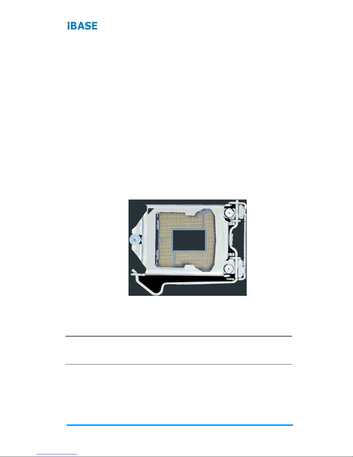
2.1.1 Installing the CPU
Follow the instructions below to install the CPU.
1. Unlock the socket by pressing the lever sideways, then lift up the
lever and the metal lid.
2. Position the CPU above the socket such that the CPU corner
aligns with the gold triangle matching the socket corner with a
small triangle.
3. Carefully insert the CPU into the socket and push down the lever
to secure the CPU.
Then you can install the CPU cooler and fan.
Note: Ensure that the CPU cooler and the CPU top surface are in total
contact to avoid CPU overheating problem that would cause your
system to hang or be unstable.

Hardware Configuration
IB981 User’s Manual
11
2
2.1.2 Installing the Memory
To install the modules, locate the memory slot on the board and
perform the following steps:
1. Hold the module so that the key of the module aligned with that
on the memory slot.
2. Gently push the module in an upright position until the clips of the
slot close to hold the module in place when the module touches
the bottom of the slot.
To remove the module, press the clips outwards with both hands

12
IB981 User’s Manual
2.2 Setting the Jumpers
Set up and configure your IB981 by using jumpers for various settings
and features according to your needs and applications. Contact your
supplier if you have doubts about the best configuration for your use.
2.2.1 How to Set Jumpers
Jumpers are short-length conductors consisting of several metal pins
with a non-conductive base mounted on the circuit board. Jumper
caps are used to have the functions and features enabled or disabled.
If a jumper has 3 pins, you can connect either PIN1 to PIN2 or PIN2 to
PIN3 by shorting.
Pin# 1
2
3
A 3-pin jumper
A jumper cap
Refer to the illustration below to set jumpers.
Pin closed
Oblique view
Schematic illustration in the manual
Open
1 2 3
1-2
1 2 3
2-3
1 2 3
When two pins of a jumper are encased in a jumper cap, this jumper
is closed, i.e. turned On.
When a jumper cap is removed from two jumper pins, this jumper is
open, i.e. turned Off.

Hardware Configuration
IB981 User’s Manual
13
2
2.3 Jumper & Connector Locations on IB981
Board diagram of IB981AF

14
IB981 User’s Manual
2.4 Jumpers Quick Reference
Function
Jumper Name
Page
Clearing CMOS Data
JBAT1
14
COM1 RS-232 Power Setting
JP1
15
Backlight Power Mode Selection
JP4
15
Backlight Control Setting
JP5
16
LVDS Panel Power Selection
JP6
16
Factory Use Only
JP7, JP9, JP11
- -
2.4.1 Clear CMOS Content (JBAT1)
1
Function
Pin closed
Illustration
Normal
(default)
1-2
1
Clear CMOS
2-3
1

Hardware Configuration
IB981 User’s Manual
15
2
2.4.2 COM1 RS232 Power Setting (JP1)
1
2
5
6
Function
Pin closed
Illustration
+12V
1-3
1
2
5
6
RI
(default)
3-4
1
2
5
6
+5V
3-5
1
2
5
6
2.4.3 Backlight Power Mode Selection (JP4)
1
Function
Pin closed
Illustration
DC Mode
(default)
1-2
1
PWM Mode
2-3
1

16
IB981 User’s Manual
2.4.4 Backlight Control Setting (JP5)
1
Function
Pin closed
Illustration
3.3V
(default)
Open
1
5V
Close
1
2.4.5 LVDS Panel Power Selection (JP6)
1
Function
Pin closed
Illustration
3.3V
(default)
1-2
1
5V
2-3
1

Hardware Configuration
IB981 User’s Manual
17
2
2.5 Connectors Quick Reference
Function
Connector Name
Page
COM1 & COM2 Serial Port
J1
18
COM3 & COM4 Serial Port
J2
19
USB 3.0 / USB 2.0 Connector
J4
20
USB 2.0 Ports
J17 (pin-header),
CN8 (vertial)
21
LCD Backlight Connector
J8
21
Front Panel Setting Connector
J3
22
External Audio Connector
J6
23
ATX 12V Power Connector
J12
24
Digital I/O 4 In/4 Out
J11
24
PS/2 KB & MS Connector
J9
25
Parallel Port
J5
26
DVI-D Port
J15
27
CPU Fan Power Connector
CPU_FAN1
28
System Fan Power Connector
SYS_FAN1
28
LVDS Connector
J13, J14
29
Wake-on_LAN Connector
J19
30
ATX 5V Power Connector
J18
30
DDR3 DIMM Socket
CN1, CN2
- -
VGA Port
CN7
- -
GbE LAN Ports
CN9
- -
Mini-PCIe Slot (with mSATA)
CN10 (related to CN5)
- -
USB 3.0 Port
CN11,CN12
- -
SATA 3.0 Connector
CN3, CN4, CN5, CN6
- -
Factory Use Only
J7, J10, J16,
- -

18
IB981 User’s Manual
2.5.1 COM1 & COM2 Serial Port (J1)
1
2
19
20
COM1 (pin1 ~ pin10) supports RS-232/422/485.
COM2 (pin11 ~ pin20) supports RS-232 only.
Pin
Assignment
Pin
Assignment
1
DCD1
2
DSR1
3
RXD1
4
RTS1
5
TXD1
6
CTS1
7
DTR1
8
RI1
9
Ground
10
NC
11
DCD2
12
DSR2
13
RXD2
14
RTS2
15
TXD2
16
CTS2
17
DTR2
18
RI2
19
Ground
20
NC
Pin
Assignment
RS-232
RS-422
RS-485
1
DCD
TX-
DATA-
3
RX
TX+
DATA+
5
TX
RX+
NC
7
DTR
RX-
NC
9
Ground
Ground
Ground
2
DSR
NC
NC
4
RTS
NC
NC
6
CTS
NC
NC
8
RI
NC
NC
10
NC
NC
NC

Hardware Configuration
IB981 User’s Manual
19
2
2.5.2 COM3 & COM4 Serial Port (J2)
1
2
19
20
COM3 (pin1 ~ pin10) and COM4 (pin11 ~ pin20) support RS-232
only.
Pin
Assignment
Pin
Assignment
1
DCD3
2
DSR3
3
RXD3
4
RTS3
5
TXD3
6
CTS3
7
DTR3
8
RI3
9
Ground
10
NC
11
DCD4
12
DSR4
13
RXD4
14
RTS4
15
TXD4
16
CTS4
17
DTR4
18
RI4
19
Ground
20
NC

20
IB981 User’s Manual
2.5.3 USB 3.0 / USB 2.0 Connector (J4)
110
11 19
Pin
Assignment
Pin
Assignment
1
VCC (900mA)
11
P2_U2_D+
2
P1_SSRX-
12
P2_U2_D-
3
P1_SSRX+
13
Ground
4
Ground
14
P2_SSTX+
5
P1_SSTX-
15
P2_SSTX-
6
P1_SSTX+
16
Ground
7
Ground
17
P2_SSRX+
8
P1_U2_D-
18
P2_SSRX-
9
P1_U2_D+
19
VCC (900mA)
10
NC

Hardware Configuration
IB981 User’s Manual
21
2
2.5.4 USB2.0 Ports (J17, CN8)
J17:
(pin-header)
CN8:
(vertical)
1
210
J17:
Pin
Assignment
Pin
Assignment
1
VCC (500mA)
2
VCC (500mA)
3
D0-
4
D1-
5
D0+
6
D1+
7
Ground
8
Ground
9
N/A
10
NC
2.5.5 LCD Backlight Connector (J8)
1
Pin
Assignment
Pin
Assignment
1
Backlight Power +12V
(2A)
3
Backlight Control
2
Backlight Enable
4
Ground

22
IB981 User’s Manual
2.5.6 Front Panel Setting Connector (J3)
1
19
20
2
Pin
Assignment
Pin
Assignment
1
VCC
2
Speaker Out
3
NC
4
NC
5
Ground
6
Ground
7
NC
8
VCC
9
Ground
10
NC
11
Ground
12
NC
13
Ground
14
PWR_SW
15
NC
16
NC
17
Ground
18
RST
19
HDD LED +
20
HDD LED -
J3 is utilized for system indicators to provide light indication of the
computer activities and switches to change the computer status. It
provides interfaces for the following functions.
• Speaker (Pins 2 ~ 8)
This connector connects to the system speaker on control
panel.
• Power LED (Pins 1 ~ 5)
This connector connects to the system power LED on control
panel. This LED will light when the system turns on.
• ATX Power ON Switch (Pins 13 and 14)
The 2 pins make an “ATX Power Supply On/Off Switch” for the
system that connects to the power switch on the case. When
pressed, the power switch will force the system to power on.
When pressed again, it will power off the system.

Hardware Configuration
IB981 User’s Manual
23
2
• Reset Switch (Pins 17 and 18)
The reset switch allows you to reset the system without turning
the main power switch off and then on again. Orientation is not
required when making a connection to this header.
• Hard Disk Drive LED Connector (Pins 19 and 20)
This connector connects to the hard drive activity LED on
control panel. This LED will flash when the HDD is being
accessed.
2.5.7 External Audio Connector (J6)
1
11
2
12
J6 is a 12-pin header that is used to connect to the optional audio
cable.
Pin
Assignment
Pin
Assignment
1
Line out_L
2
Line out_R
3
JD_FRONT
4
Ground
5
LINE IN_L
6
Line in_R
7
JD_LINE IN
8
Ground
9
MIC-L
10
MIC-R
11
JD_MIC1
12
Ground

24
IB981 User’s Manual
2.5.8 ATX 12V Power Connector (J12)
4
2
3
1
J12 connector supplies the CPU operating voltage.
Pin
Assignment
Pin
Assignment
1
Ground
2
Ground
3
+12V-IN
4
+12V-IN
2.5.9 Digital I/O 4 In/4 Out (J11)
9
1
10
2
Pin
Assignment
Pin
Assignment
1
Ground
2
VCC (500mA)
3
OUT3
4
OUT1
5
OUT2
6
OUT0
7
IN3
8
IN1
9
IN2
10
IN0

Hardware Configuration
IB981 User’s Manual
25
2
2.5.10 PS/2 KB & MS Connector (J9)
7
2
8
1
Pin
Assignment
Pin
Assignment
1
VCC (300mA)
2
VCC (300mA)
3
MS_DATA
4
KB_DATA
5
MS_CLK
6
KB_CLK
7
Ground
8
Ground

26
IB981 User’s Manual
2.5.11 Parallel Port (J5)
1
14 26
13
J5 is a 26-pin header used to connect to the optional printer port
cable.
Pin
Assignment
Pin
Assignment
1
Line printer strobe
14
Auto Feed
2
PD0, parallel data 0
15
Error
3
PD1, parallel data 1
16
Initialize
4
PD2, parallel data 2
17
Select
5
PD3, parallel data 3
18
Ground
6
PD4, parallel data 4
19
Ground
7
PD5, parallel data 5
20
Ground
8
PD6, parallel data 6
21
Ground
9
PD7, parallel data 7
22
Ground
10
ACK, acknowledge
23
Ground
11
Busy
24
Ground
12
Paper empty
25
Ground
13
Select
26
Ground

Hardware Configuration
IB981 User’s Manual
27
2
2.5.12 DVI-D Port (J15)
1
2
19
20
Pin
Assignment
Pin
Assignment
1
TDC1_B
2
TDC1#_B
3
Ground
4
Ground
5
TLC_B
6
TLC#_B
7
Ground
8
5V 9 HPDET_B
10
N.C.
11
TDC2_B
12
TDC2#_B
13
Ground
14
Ground
15
TDC0_B
16
TDC0#_B
17
N.C.
18
N.C.
19
SD_DDC_B
20
SC_DDC_B

28
IB981 User’s Manual
2.5.13 CPU Fan Power Connector (CPU_FAN1)
1
Pin
Assignment
Pin
Assignment
1
Ground
3
Rotation detection
2
+12V (1A)
4
Control
2.5.14 System Fan Power Connector (SYS_FAN1)
1
Pin
Assignment
Pin
Assignment
1
Ground
3
Rotation detection
2
+12V (1A)

Hardware Configuration
IB981 User’s Manual
29
2
2.5.15 LVDS Connector (J13, J14)
J13 (1st channel)
J14 (2nd channel)
1
2
19
20
Pin
Assignment
Pin
Assignment
1
LD0+
2
LD0-
3
Ground
4
Ground
5
LD1+
6
LD1-
7
Ground
8
Ground
9
LD2+
10
LD2-
11
Ground
12
Ground
13
CLK+
14
CLK-
15
Ground
16
Ground
17
LD3+
18
LD3-
19
LCD_PWR (1A)
20
LCD_PWR (1A)

30
IB981 User’s Manual
2.5.16 Wake-on_LAN Connector (J19)
1
Pin
Assignment
Pin
Assignment
1
+5VSB
3
-PME
2
Ground
2.5.17 ATX 5V Power Connector (J18)
1
Connect the J18 connector to the ATX power connector of your
backplane.
Pin
Assignment
Pin
Assignment
1
Ground
3
+5VSB-IN
2
PS_On

31
Chapter 3
Drivers Installation
This chapter introduces installation of the following drivers:
• Intel® Chipset Software Installation Utility
• Graphics Driver
• HD Audio Driver
• LAN Driver
• Intel® Management Engine Interface
• Intel® USB 3.0 Driver

32
IB981 User’s Manual
3.1 Introduction
This section describes the installation procedures for software and
drivers. The software and drivers are included with the motherboard.
If you find anything missing, please contact the distributor where you
made the purchase. The contents of this section include the following:
Note: After installing your Windows operating system, you must install first
the Intel Chipset Software Installation Utility before proceeding with
the drivers installation.
3.2 Intel® Chipset Software Installation Utility
The Intel® Chipset drivers should be installed first before the software
drivers to install INF files for Plug & Play function for Intel chipset
components. Follow the instructions below to complete the
installation.
1. Insert the disk enclosed in the package with the board. Click Intel
and then Intel(R) 8 Series Chipset Drivers.

Driver Installation
IB981 User’s Manual
33
3
2. Click Intel(R) Chipset Software Installation Utility.
3. When the Welcome screen to the Intel
®
Chipset Device Software
appears, click Next to continue.
4. Click Yes to accept the software license agreement and proceed
with the installation process.
5. On the Readme File Information screen, click Install for
installation.
6. The driver has been completely installed. Click Finish and
restart the computer for changes to take effect.

34
IB981 User’s Manual
3.3 Graphics Driver Installation
1. Click Intel and then Intel(R) 8 Series Chipset Drivers.
2. Click Intel(R) HD Graphics Driver.

Driver Installation
IB981 User’s Manual
35
3
3. When the Welcome screen appears, click Next to continue.
4. Click Yes to agree with the license agreement and continue the
installation.
5. On the Windows Security screen shown below, click Install to
continue.
6. The driver has been completely installed. Click Finish and
restart the computer for changes to take effect.

36
IB981 User’s Manual
3.4 HD Audio Driver Installation
1. Click Intel and then Intel(R) 8 Series Chipset Drivers.
2. Click Realtek High Definition Audio Driver.

Driver Installation
IB981 User’s Manual
37
3
3. On the Welcome screen of the InstallShield Wizard, click Yes for
proceed.
4. The installation is complete. Click Finish and restart the
computer for changes to take effect.

38
IB981 User’s Manual
3.5 LAN Driver Installation
1. Click Intel and then Intel(R) 8 Series Chipset Drivers.
2. Click Intel(R) PRO LAN Network Drivers.

Driver Installation
IB981 User’s Manual
39
3
3. On the screen of Intel® Network Connections, click Install
Drivers and Software.
4. When the Welcome screen appears, click Next.
5. Click Next to to agree with the license agreement.
6. On the Setup Options screen, click the checkbox to select the
desired driver(s) for installation. Then click Next to continue.
7. The wizard is ready for installation. Click Install.
8. As the installation is complete, click Finish and restart the
computer for changes to take effect.

40
IB981 User’s Manual
3.6 Intel® Management Engine Interface
Before installation, please pay attention to the warning message
below.
1. Click Intel and then Intel(R) 8 Series Chipset Drivers.
2. Click Intel(R) ME 9.0 Drivers.

Driver Installation
IB981 User’s Manual
41
3
3. When the Welcome screen to the InstallS hield Wizard for Intel®
Management Engine Components appears, click Next.
4. Click Yes to to agree with the license agreement.
5. When the Setup Progress screen appears, click Next.

42
IB981 User’s Manual
6. As the driver has been sccessfully installed, click Finish and
restart the computer for changes to take effect.

Driver Installation
IB981 User’s Manual
43
3
3.7 Intel® USB 3.0 Driver
1. Click Intel and then Intel(R) 8 Series Chipset Drivers.
2. Click Intel(R) USB 3.0 Drivers.

44
IB981 User’s Manual
3. When the Welcome screen to the InstallS hield Wizard for Intel
®
USB 3.0 eXtensible Host Controller Driver appears, click Next.
4. Click Yes to to agree with the license agreement.
5. On the Readme File Information screen, click Next for
installation.

Driver Installation
IB981 User’s Manual
45
3
6. The driver has been successfully installed. Click Finish and
restart the computer for changes to take effect.

46
IB981 User’s Manual
This page is intentionally left blank.

47
Chapter 4
BIOS Setup
This chapter describes the different settings available in the AMI
BIOS that comes with the board. The topics covered in this
chapter are as follows:
• Main Settings
• Advanced Settings
• Chipset Settings
• Security Settings
• Book Settings
• Save & Exit

48
IB981 User’s Manual
4.1 Introduction
The BIOS (Basic Input/Output System) installed in the ROM of your
computer system supports Intel® processors. The BIOS provides
critical low-level support for standard devices such as disk drives,
serial ports and parallel ports. It also provides password protection as
well as special support for detailed fine-tuning of the chipset
controlling the entire system.
4.2 BIOS Setup
The BIOS provides a Setup utility program for specifying the system
configurations and settings. The BIOS ROM of the system stores the
Setup utility. When you turn on the computer, the BIOS is immediately
activated. Press the <Del> key immediately allows you to enter the
Setup utility. If you are a little bit late pressing the <Del> key, POST
(Power On Self Test) will continue with its test routines, thus
preventing you from invoking the Setup.
If you still need to enter Setup, restart the system by pressing
the ”Reset” button or simultaneously pressing the <Ctrl>, <Alt> and
<Delete> keys.
You can also restart by turning the system Off and back On again.
The following message will appear on the screen:
Press <DEL> to Enter Setup
In general, press the arrow keys to highlight items, <Enter> to select,
the <PgUp> and <PgDn> keys to change entries, <F1> for help, and
<Esc> to quit.

BIOS Setup
IB981 User’s Manual
49
4
When you enter the BIOS Setup utility, the Main Menu screen will
appear on the screen. The Main Menu allows you to select from
various setup functions and exit choices.
Warning: It is strongly recommended that you avoid making any changes to
the chipset defaults.
These defaults have been carefully chosen by both AMI and your
system manufacturer to provide the absolute maximum
performance and reliability. Changing the defaults could make the
system unstable and crash in some cases.

50
IB981 User’s Manual
4.3 Advanced Settings
This section allows you to configure, improve your system and allows
you to set up some system features according to your preference.

BIOS Setup
IB981 User’s Manual
51
4
4.3.1 ACPI Settings
BIOS Setting
Description
Enable Hibernation
Enables / Disables the system ability to
hibernate (OS/S4 Sleep State). This option
may be not effective with some OS.
ACPI Sleep State
Selects an ACPI sleep state where the
system will enter when the Suspend button is
pressed.

52
IB981 User’s Manual
4.3.2 Trusted Computing
BIOS Setting
Description
Security Device
Support
Enables / Disables TPM support. O.S. will
not show TPM. Reset of platform is required.
Note: This feature is not supported on
IB981F.

BIOS Setup
IB981 User’s Manual
53
4
4.3.3 Wakeup Event Configuration
BIOS Setting
Description
Wake up by PCI
PME#
Wakes up the device by PCI PME#.
Wake up by PCIE
WAKE#
Wakes up the device by PCIE WAKE#.

54
IB981 User’s Manual
4.3.4 CPU Configuration
BIOS Setting
Description
Hyper-Threading
Enabled for Windows XP and Linux (OS
optimized for Hhyper-Threading
Technology) and Disabled for other OS (OS
not optimized for Hyper-Threading
Technology).
Active Processor
Cores
Number of cores to enable in each processor
package.
Options: All, 1, 2, 3
Execute Disable Bit
Enables / Disables the Execute Disable Bit.
Intel Virtualization
Technology
Enables / Disables a VMM to utilize the
additional hardware capabilities provided by
Vanderpool Technology.
EIST
Enables / Disables EIST.
Turbo Mode
Enables / Disables the Turbo Mode.
Intel TXT(LT)
Support
Enables / Disables Intel TXT (LT) function.

BIOS Setup
IB981 User’s Manual
55
4
4.3.5 SATA Configuration
BIOS Setting
Description
SATA Controller(s)
Enables / Disables SATA devices.
SATA Mode
Selection
Determines how the SATA controller(s)
operate.
• AHCI Mode
• RAID Mode
Hot Plug
Designates this port as Hot Pluggable.

56
IB981 User’s Manual
4.3.6 LVDS Configuration
BIOS Setting
Description
LVDS (eDP/DP)
Controller
Enables / Disables LVDS (eDP/DP) device.

BIOS Setup
IB981 User’s Manual
57
4
4.3.7 iSmart Configuration
BIOS Setting
Description
Power-On after
Power failure
Enables / Disables the system to be turned
on automatically after a power failure.
Power Resume
Delay
Enables / Disables to delay the time for
system to turn on.
Temperature
Guardian
Generate the reset signal when system
hands up on POST.
Schedule Slot 1 / 2
Sets up the hour / minute / day for the
power-on schedule for the system.
Options: None, Power On, Power On / Off
Important: If you would like to set up a
schedule between adjacent days, configure
two schedule slots.
For example, if setting up a schedule from
Wednesday 5 p.m. to Thursday 2 a.m.,
configure two schedule slots. But if setting up
a schedule from 3 p.m to 5 p.m. on
Wednesday, configure only a schedule slot.

58
IB981 User’s Manual
4.3.8 AMT Configuration
BIOS Setting
Description
Intel AMT
Enables / Disables AMT configuration.
Note: iAMT H/W is always enabled. This
option just controls the BIOS extension
execution. If enabled, this requires additional
firmware in the SPI device.
Hide Unconfigure
ME
Hides Unconfigures ME without password
operation.
Unconfigure ME
Unconfigures AMT/ME without password
operation.
Amt Wait Timer
Sets timer to wait before sending
ASF_GET_BOOT_OPTIONS.
Activate Remote
Assistance Process
Triggers CIRA boot.
PET Progress
Enables / Disables PET events progress to
receive PET events.
WatchDog
Enables / Disables Watchdog Timer.

BIOS Setup
IB981 User’s Manual
59
4
4.3.9 USB Configuration
BIOS Setting
Description
Legacy USB
Support
Enables Legacy USB support.
“Auto” disables legacy support if there is no
USB device connected.
“Disable” keeps USB devices available only
for EFI applications.
XHCI Hand-off
This is a workaround for OSes without XHCI
hand-off support. The XHCI ownership
change should be claimed by XHCI driver.
EHCI Hand-off
Enabled / Disabled. This is a workaround for
OSes without EHCI hand-off support. The
EHCI ownership change should be claimed
by EHCI driver.
USB Mass Storage
Driver Support
Enables / Disables the support for USB
mass storage driver.
USB Transfer
time-out
The time-out value for Control, Bulk, and
Interrupt transfers.

60
IB981 User’s Manual
BIOS Setting
Description
Device reset
time-out
Seconds of delaying execution of start unit
command to USB mass storage device.
Device power-up
delay
The maximum time the device will take
before it properly reports itself to the Host
Controller.
“Auto” uses default value for a Root port it is
100ms. But for a Hub port, the delay is taken
from Hub descriptor.

BIOS Setup
IB981 User’s Manual
61
4
4.3.10 F81846 Super IO Configuration
BIOS Setting
Description
Serial Port
Configuration
Sets parameters of Serial Ports. Enables /
Disables the serial port and select an optimal
setting for the Super IO device.
BIOS Setting
Description
Multi Function
There is a risk of permanent damage to
electronic equipment if RS-232 equipment is
connected to RS-422/485 equipment.
Opotions: RS-232, RS-422, RS-485

62
IB981 User’s Manual
4.3.11 Hardware Monitor
BIOS Setting
Description
Smart Fan 1 / 2
Function
Enables / Disables the smart fan feature.
Options: Disabled (default) / 50 °C /
60 °C / 70 °C / 80 °C / 90 °C
Temperatures/Voltages
These fields are the parameters of the
hardware monitoring function feature of
the motherboard. The values are
read-only values as monitored by the
system and show the PC health status.

BIOS Setup
IB981 User’s Manual
63
4
4.4 Chipset Settings
BIOS Setting
Description
PCH-IO
Configuration
PCH parameters
System Agent (SA)
Configuration
System Agent (SA) parameters

64
IB981 User’s Manual
4.4.1 PCI Express Configuration
BIOS Setting
Description
PCI Express
Configuration
PCI Express Configuration settings.

BIOS Setup
IB981 User’s Manual
65
4
4.4.1.1. USB Configuration
BIOS Setting
Description
USB Configuration
Precondition work on USB host controller
and root ports for faster enumeration.

66
IB981 User’s Manual
4.4.2 System Agent (SA) Configuration
BIOS Setting
Description
VT-d
Checks if VT-d function on MCH is
supported.

BIOS Setup
IB981 User’s Manual
67
4
4.4.2.1. Graphics Configuration
BIOS Setting
Description
Internal Graphics
Keeps IGD enabled based on the setup
options.
4.4.2.2. Memory Configuration

68
IB981 User’s Manual
4.5 Boot Settings
BIOS Setting
Description
Setup Prompt
Timeout
Number of seconds to wait for setup
activation key.
65535(0xFFFF) means indefinite waiting.
Bootup NumLock
State
Selects the keyboard NumLock state.
Quiet Boot
Enables / Disables Quiet Boot option.
Fast Boot
Enables / Disables boot with initialization of a
minimal set of devices required to launch
active boot option. Has no effect for BBS
boot options.

BIOS Setup
IB981 User’s Manual
69
4
4.6 Security Settings
BIOS Setting
Description
Administrator
Password
Sets an administrator password for the setup
utility.
User Password
Sets a user password.

70
IB981 User’s Manual
4.7 Save & Exit Settings
BIOS Setting
Description
Save Changes and
Exit
Exits system setup after saving the changes.
Discard Changes
and Exit
Exits system setup without saving any
changes.
Save Changes and
Reset
Resets the system after saving the changes.
Discard Changes
and Reset
Resets system setup without saving any
changes.
Save Changes
Saves changes done so far to any of the
setup options.
Discard Changes
Discards changes done so far to any of the
setup options.
Restore Defaults
Restores / Loads defaults values for all the
setup options.

BIOS Setup
IB981 User’s Manual
71
4
BIOS Setting
Description
Save as User
Defaults
Saves the changes done so far as User
Defaults.
Restore User
Defaults
Restores the user defaults to all the setup
options.

72
IB981 User’s Manual
This page is intentionally left blank.

73
Appendix
This section provides the mapping addresses of peripheral
devices and the sample code of watchdog timer configuration.

74
IB981 User’s Manual
A. I/O Port Address Map
Each peripheral device in the system is assigned a set of I/O port
addresses which also becomes the identity of the device. The
following table lists the I/O port addresses used.
Address
Device Description
0x0000FFFF-0x0000FFFF
Motherboard Resource
0x0000FFFF-0x0000FFFF
Motherboard Resource
0x0000FFFF-0x0000FFFF
Motherboard Resource
0x0000F0E0-0x0000F0E7
Standard SATA AHCI Controller
0x0000F0D0-0x0000F0D3
Standard SATA AHCI Controller
0x0000F0C0-0x0000F0C7
Standard SATA AHCI Controller
0x0000F0B0-0x0000F0B3
Standard SATA AHCI Controller
0x0000F0A0-0x0000F0A7
Intel(R) Active Management
Technology - SOL (COM5)
0x0000F080-0x0000F09F
Standard SATA AHCI Controller
0x0000F060-0x0000F07F
Intel(R) 8 Series/C220 Series
SMBus Controller - 8C22
0x0000F000-0x0000F03F
Intel(R) HD Graphics P4600/P4700
0x0000E000-0x0000EFFF
Intel(R) 8 Series/C220 Series PCI
Express Root Port #3 - 8C14
0x00001F00-0x00001FFE
Motherboard Resource
0x00001E00-0x00001EFE
Motherboard Resource
0x00001D00-0x00001DFE
Motherboard Resource
0x00001C00-0x00001CFE
Motherboard Resource
0x00001854-0x00001857
Motherboard Resource
0x00001800-0x000018FE
Motherboard Resource
0x0000164E-0x0000164F
Motherboard Resource
0x00000D00-0x0000FFFF
PCI Express Root Complex

Appendix
IB981 User’s Manual
75
Address
Device Description
0x00000680-0x0000069F
Motherboard Resource
0x000004D0-0x000004D1
Programmable Interrupt Controller
0x000004D0-0x000004D1
Motherboard Resource
0x000003F8-0x000003FF
Communications Port (COM1)
0x000003E8-0x000003EF
Communications Port (COM3)
0x000003C0-0x000003DF
Intel(R) HD Graphics P4600/P4700
0x000003B0-0x000003BB
Intel(R) HD Graphics P4600/P4700
0x00000378-0x0000037F
Printer Port (LPT1)
0x000002F8-0x000002FF
Communications Port (COM2)
0x000002E8-0x000002EF
Communications Port (COM4)
0x000002A0-0x000002AF
Motherboard Resource
0x00000290-0x0000029F
Motherboard Resource
0x00000280-0x0000028F
Motherboard Resource
0x000000F0-0x000000F0
Numeric data processor
0x000000E0-0x000000EF
Motherboard Resource
0x000000C0-0x000000DF
Memory Controller
0x000000BC-0x000000BD
Programmable Interrupt Controller
0x000000B8-0x000000B9
Programmable Interrupt Controller
0x000000B4-0x000000B5
Programmable Interrupt Controller
0x000000B2-0x000000B3
Motherboard Resource
0x000000B0-0x000000B1
Programmable Interrupt Controller
0x000000AC-0x000000AD
Programmable Interrupt Controller
0x000000A8-0x000000A9
Programmable Interrupt Controller
0x000000A4-0x000000A5
Programmable Interrupt Controller
0x000000A2-0x000000BF
Motherboard Resource
0x000000A0-0x000000A1
Programmable Interrupt Controller

76
IB981 User’s Manual
Address
Device Description
0x00000093-0x0000009F
Memory Controller
0x00000092-0x00000092
Motherboard Resource
0x00000090-0x0000009F
Motherboard Resource
0x0000008C-0x0000008E
Motherboard Resource
0x00000088-0x00000088
Motherboard Resource
0x00000084-0x00000086
Motherboard Resource
0x00000081-0x00000091
Memory Controller
0x00000080-0x00000080
Motherboard Resource
0x00000080-0x00000080
Motherboard Resource
0x00000072-0x0000007F
Motherboard Resource
0x00000070-0x00000070
Motherboard Resource
0x00000070-0x00000070
System CMOS/real time clock
0x00000067-0x00000067
Motherboard Resource
0x00000065-0x00000065
Motherboard Resource
0x00000065-0x00000065
Motherboard Resource
0x00000064-0x00000064
Standard PS/2 Keyboard
0x00000063-0x00000063
Motherboard Resource
0x00000062-0x00000063
Motherboard Resource
0x00000061-0x00000061
Motherboard Resource
0x00000060-0x00000060
Standard PS/2 Keyboard
0x00000050-0x00000053
System timer
0x0000004E-0x0000004F
Motherboard Resource
0x00000044-0x0000005F
Motherboard Resource
0x00000040-0x00000043
System timer
0x0000003C-0x0000003D
Programmable Interrupt Controller
0x00000038-0x00000039
Programmable Interrupt Controller

Appendix
IB981 User’s Manual
77
Address
Device Description
0x00000034-0x00000035
Programmable Interrupt Controller
0x00000030-0x00000031
Programmable Interrupt Controller
0x0000002E-0x0000002F
Motherboard Resource
0x0000002C-0x0000002D
Programmable Interrupt Controller
0x00000028-0x00000029
Programmable Interrupt Controller
0x00000024-0x00000025
Programmable Interrupt Controller
0x00000022-0x0000003F
Motherboard Resource
0x00000020-0x00000021
Programmable Interrupt Controller
0x00000010-0x0000001F
Motherboard Resource
0x00000000-0x0000001F
Memory Controller
0x00000000-0x0000001F
PCI Express Root Complex

78
IB981 User’s Manual
B. Interrupt Request Lines (IRQ)
Peripheral devices use interrupt request lines to notify CPU for the
service required. The following table shows the IRQ used by the
devices on board.
Level
Function
IRQ 1
Standard PS/2 Keyboard
IRQ 4294967293
Intel(R) 8 Series/C220 Series PCI Express
Root Port #1 - 8C10
IRQ 4294967292
Intel(R) 8 Series/C220 Series PCI Express
Root Port #3 - 8C14
IRQ 4294967287
Intel(R) Management Engine Interface
IRQ 22
High Definition Audio Controller
IRQ 10
Intel(R) 8 Series/C220 Series SMBus
Controller - 8C22
IRQ 23
Intel(R) 8 Series/C220 Series USB EHCI
#1 - 8C26
IRQ 16
Intel(R) 8 Series/C220 Series USB EHCI
#2 - 8C2D
IRQ 13
Numeric data controller
IRQ 4
Communications Port (COM1)
IRQ 3
Communications Port (COM2)
IRQ 11
Communications Port (COM3)
IRQ 7
Communications Port (COM4)
IRQ 4294967288
Intel(R) USB 3.0 eXtensible Host Controller
- 1.0 (Microsoft)
IRQ 12
Microsoft PS/2 Mouse
IRQ 0
System timer
IRQ 54 ~ IRQ 204
Microsoft ACPI-Compliant System
IRQ 256 ~ IRQ 511
Microsoft ACPI-Compliant System

Appendix
IB981 User’s Manual
79
Level
Function
IRQ 4294967286
Intel(R) Ethernet Connection I217-LM
IRQ 19
Intel(R) Active Management Technology SOL (COM5)
IRQ 4294967294
Intel(R) Xeon(R) processor E3 - 1200
v3/4th Gen Core processor PCI Express
x16 Controller - 0C01
IRQ 4294967285
Intel(R) I211 Gigabit Network Connection
IRQ 4294967284
Intel(R) I211 Gigabit Network Connection
IRQ 4294967283
Intel(R) I211 Gigabit Network Connection
IRQ 4294967282
Intel(R) I211 Gigabit Network Connection
IRQ 4294967281
Intel(R) I211 Gigabit Network Connection
IRQ 4294967280
Intel(R) I211 Gigabit Network Connection
IRQ 4294967290
Standard SATA AHCI Controller
IRQ 4294967283
Intel(R) I211 Gigabit Network Connection
IRQ 4294967282
Intel(R) I211 Gigabit Network Connection
IRQ 4294967281
Intel(R) I211 Gigabit Network Connection
IRQ 4294967280
Intel(R) I211 Gigabit Network Connection
IRQ 4294967290
Standard SATA AHCI Controller
IRQ 4294967291
PCI Express Root Port
IRQ 4294967289
Intel(R) HD Graphics P4600/P4700
IRQ 8
System CMOS/real time clock

80
IB981 User’s Manual
C. Watchdog Timer Configuration
The Watchdog Timer (WDT) is used to generate a variety of output
signals after a user programmable count. The WDT is suitable for use
in the prevention of system lock-up, such as when software becomes
trapped in a deadlock. Under these sorts of circumstances, the timer
will count to zero and the selected outputs will be driven.
Under normal circumstance, you will need to restart the WDT at
regular intervals before the timer counts to zero.
Sample Code:
//--------------------------------------------------------------------------//
// THIS CODE AND INFORMATION IS PROVIDED "AS IS" WITHOUT WARRANTY OF ANY
// KIND, EITHER EXPRESSED OR IMPLIED, INCLUDING BUT NOT LIMITED TO THE
// IMPLIED WARRANTIES OF MERCHANTABILITY AND/OR FITNESS FOR A PARTICULAR
// PURPOSE.
//
//--------------------------------------------------------------------------#include <dos.h>
#include <conio.h>
#include <stdio.h>
#include <stdlib.h>
#include "F81866.H"
//--------------------------------------------------------------------------int main (int argc, char *argv());
void EnableWDT(int);
void DisableWDT(void);
//--------------------------------------------------------------------------int main (int argc, char *argv())
{
unsigned char bBuf;
unsigned char bTime;
char **endptr;
char SIO;
printf("Fintek 81866 watch dog program\n");
SIO = Init_F81866();
if (SIO == 0)
{
printf("Can not detect Fintek 81866, program abort.\n");
return(1);
}//if (SIO == 0)
if (argc != 2)
{
printf(" Parameter incorrect!!\n");
return (1);
}
bTime = strtol (argv(1), endptr, 10);
printf("System will reset after %d seconds\n", bTime);
if (bTime)
{ EnableWDT(bTime); }
else

Appendix
IB981 User’s Manual
81
{ DisableWDT(); }
return 0;
}
//--------------------------------------------------------------------------void EnableWDT(int interval)
{
unsigned char bBuf;
bBuf = Get_F81866_Reg(0x2B);
bBuf &= (~0x20);
Set_F81866_Reg(0x2B, bBuf); //Enable WDTO
Set_F81866_LD(0x07);
//switch to logic device 7
Set_F81866_Reg(0x30, 0x01); //enable timer
bBuf = Get_F81866_Reg(0xF5);
bBuf &= (~0x0F);
bBuf |= 0x52;
Set_F81866_Reg(0xF5, bBuf); //count mode is second
Set_F81866_Reg(0xF6, interval); //set timer
bBuf = Get_F81866_Reg(0xFA);
bBuf |= 0x01;
Set_F81866_Reg(0xFA, bBuf); //enable WDTO output
bBuf = Get_F81866_Reg(0xF5);
bBuf |= 0x20;
Set_F81866_Reg(0xF5, bBuf); //start counting
}
//--------------------------------------------------------------------------void DisableWDT(void)
{
unsigned char bBuf;
Set_F81866_LD(0x07);
//switch to logic device 7
bBuf = Get_F81866_Reg(0xFA);
bBuf &= ~0x01;
Set_F81866_Reg(0xFA, bBuf);
//disable WDTO output
bBuf = Get_F81866_Reg(0xF5);
bBuf &= ~0x20;
bBuf |= 0x40;
Set_F81866_Reg(0xF5, bBuf);
//disable WDT
}
//--------------------------------------------------------------------------//
// THIS CODE AND INFORMATION IS PROVIDED "AS IS" WITHOUT WARRANTY OF ANY
// KIND, EITHER EXPRESSED OR IMPLIED, INCLUDING BUT NOT LIMITED TO THE
// IMPLIED WARRANTIES OF MERCHANTABILITY AND/OR FITNESS FOR A PARTICULAR
// PURPOSE.
//
//--------------------------------------------------------------------------#include "F81866.H"
#include <dos.h>
//--------------------------------------------------------------------------unsigned int F81866_BASE;
void Unlock_F81866 (void);
void Lock_F81866 (void);

82
IB981 User’s Manual
//--------------------------------------------------------------------------unsigned int Init_F81866(void)
{
unsigned int result;
unsigned char ucDid;
F81866_BASE = 0x4E;
result = F81866_BASE;
ucDid = Get_F81866_Reg(0x20);
if (ucDid == 0x07)
//Fintek 81866
{ goto Init_Finish; }
F81866_BASE = 0x2E;
result = F81866_BASE;
ucDid = Get_F81866_Reg(0x20);
if (ucDid == 0x07)
//Fintek 81866
{ goto Init_Finish; }
F81866_BASE = 0x00;
result = F81866_BASE;
Init_Finish:
return (result);
}
//--------------------------------------------------------------------------void Unlock_F81866 (void)
{
outportb(F81866_INDEX_PORT, F81866_UNLOCK);
outportb(F81866_INDEX_PORT, F81866_UNLOCK);
}
//--------------------------------------------------------------------------void Lock_F81866 (void)
{
outportb(F81866_INDEX_PORT, F81866_LOCK);
}
//--------------------------------------------------------------------------void Set_F81866_LD( unsigned char LD)
{
Unlock_F81866();
outportb(F81866_INDEX_PORT, F81866_REG_LD);
outportb(F81866_DATA_PORT, LD);
Lock_F81866();
}
//--------------------------------------------------------------------------void Set_F81866_Reg( unsigned char REG, unsigned char DATA)
{
Unlock_F81866();
outportb(F81866_INDEX_PORT, REG);
outportb(F81866_DATA_PORT, DATA);
Lock_F81866();
}
//--------------------------------------------------------------------------unsigned char Get_F81866_Reg(unsigned char REG)
{
unsigned char Result;
Unlock_F81866();
outportb(F81866_INDEX_PORT, REG);
Result = inportb(F81866_DATA_PORT);
Lock_F81866();
return Result;
}
//--------------------------------------------------------------------------//
// THIS CODE AND INFORMATION IS PROVIDED "AS IS" WITHOUT WARRANTY OF ANY
// KIND, EITHER EXPRESSED OR IMPLIED, INCLUDING BUT NOT LIMITED TO THE
// IMPLIED WARRANTIES OF MERCHANTABILITY AND/OR FITNESS FOR A PARTICULAR
// PURPOSE.
//

Appendix
IB981 User’s Manual
83
//--------------------------------------------------------------------------#ifndef __F81866_H
#define __F81866_H 1
//--------------------------------------------------------------------------#define F81866_INDEX_PORT (F81866_BASE)
#define F81866_DATA_PORT (F81866_BASE+1)
//--------------------------------------------------------------------------#define F81866_REG_LD 0x07
//--------------------------------------------------------------------------#define F81866_UNLOCK 0x87
#define F81866_LOCK 0xAA
//--------------------------------------------------------------------------unsigned int Init_F81866(void);
void Set_F81866_LD( unsigned char);
void Set_F81866_Reg( unsigned char, unsigned char);
unsigned char Get_F81866_Reg( unsigned char);
//--------------------------------------------------------------------------#endif //__F81866_H

84
IB981 User’s Manual
D. On-Board Connector Types
Function
Connector
Name
Type
COM1 & COM2 Serial Port
J1
HRS_DF11-20DP-2DSA(08)
COM3 & COM4 Serial Port
J2
HRS_DF11-20DP-2DSA(08)
USB 3.0 / USB 2.0
Connector
J4
PINREX_52X-40-20GU52
LCD Backlight Connector
J8
E-CALL_0110-161-040
External Audio Connector
J6
HK_DF11-12S-PA66H
ATX 12V Power
Connector
J12
Win_WPO-04D4TN431UW
PS/2 KB & MS Connector
J9
HK_DF11-8S-PA66H
Parallel Port
J5
Win_F-WBOX-26RN
DVI-D Port
J15
HK_DF11-20S-PA66H
LVDS Connector
J13, J14
HIROSE_DF20G-20DP-1V(56)
 Loading...