

FWA6304-D25
Network Appliance
User
s Manual
Version 1.0

FWA6304-D25 Series
User’s
Manual
1
Table of Contents
Chapter 1
Introduction ...................................................................................................................... 3
Chapter 2
System Specification ....................................................................................................... 4
Chapter 3
Hardware Configuration ................................................................................................... 5
Chapter 4
Console Mode Information ............................................................................................. 10
Chapter 5
Opening the chassis ...................................................................................................... 12
Chapter 6
Installing CompactFlash Card ........................................................................................ 12
Chapter 7
Installing Memory Module .............................................................................................. 13
Chapter 8
Installing 2.5” SSD
......................................................................................................... 14
Chapter 9
Installing Mini PCI-e Module .......................................................................................... 15
Chapter 10 Lock Power Connector .................................................................................................. 15

FWA6304-D25 Series
User’s
Manual
2
Foreword
To prevent damage to the system board, please handle it with care and follow the measures below,
which are generally sufficient to protect your equipment from static electricity discharge:
When handling the board, use a grounded wrist strap designed for static discharge elimination grounded
to a metal object before removing the board from the antistatic bag. Handle the board by its edges only;
do not touch its components, peripheral chips, memory modules or gold contacts.
When handling processor chips or memory modules, avoid touching their pins or gold edge fingers.
Return the Network Appliance system board and peripherals back into the antistatic bag when not in use
or not installed in the chassis.
Some circuitry on the system board can continue to operate even though the power is switched off.
Under no circumstances should the Lithium battery cell used to power the real-time clock be allowed to
be shorted. The battery cell may heat up under these conditions and present a burn hazard.
WARNING!
1. "CAUTION: DANGER OF EXPLOSION IF BATTERY IS INCORRECTLY REPLACED.
REPLACE ONLY WITH SAME OR EQUIVALENT TYPE RECOMMENDED BY THE
MANUFACTURER. DISCARD USED BATTERIES ACCORDING TO THE
MANUFACTURER’S INSTRUCTIONS"
2. This guide is for technically qualified personnel who have experience installing and configuring
system boards. Disconnect the system board power supply from its power source before you
connect/disconnect cables or install/remove any system board components. Failure to do this can
result in personnel injury or equipment damage.
3. Avoid short-circuiting the lithium battery; this can cause it to superheat and cause burns if touched.
4. Do not operate the processor without a thermal solution. Damage to the processor can occur in
seconds.
5. Do not block air vents at least minimum 1/2-inch clearance required.
6. In case explosion, you should change battery with same specification.

FWA6304-D25 Series
User’s
Manual
3
Chapter 1 Introduction
The FWA6304-D25 series was specifically designed for the network security
& management market.
Network Security Applications:
• Firewall
• Virtual Private Network
• Proxy Server
• Caching Server
Network Management Applications:
• Load balancing
• Quality of Service
• Remote Access Service
The FWA network appliance product line covers the spectrum from offering
platforms designed for :
• SOHO
• SMB
• Enterprise
Each product is designed to address the distinctive requirements of its
respective market segment from cost effective entry-level solutions to
high throughput and performance-bound systems for the Enterprise level.

FWA6304-D25 Series
User’s
Manual
4
Chapter 2 System Specification
Product Description
FWA6304-D25 incorporates Intel® NM10 chipset. Currently, it is available in the following model:
Model Intel® Atom Dual Core CPU Watchdog Timer
FWA6304-D25 Atom D2550 1.86 GHz Yes
FWA6304-D25 Features
Supports four intel® 10/100/1000 LAN ports
DDR3 SO-DIMM x 1, up to 4GB
Mini PCI-e (USB Signal) slot, Mini PCI slot & Compact Flash socket
LAN bypass Enable / Disable pre-setting by BIOS when power on / off
FWA6304-D25 Specifications
Form Factor 5.25” Disk Size SBC
CPU Type
Operating Frequency
Intel “Cedar view” Processor, 32nm Bulk
Atom D2550 = 1.86 GHz [TDP= 10W], Cores = Dual Core
Chipset
Intel “Tiger Point” PCH, CG82NM10 [TDP = 2.1W, 130 nm]
BIOS AMI BIOS w/ACPI
Ethernet controller
Intel 82583V PCI Express Gigabit ethernet controller x4
Memory
CPU on-die memory controller supporting up to 4GB
One DDR3-1066 SO-DIMM socket, Non-ECC, unbuffered, 1.5V
LAN
Console: RS-232 @ RJ45
Eth1, 2, 3 & 4: Intel 82583V @ RJ45 with LED
Network Bypass
One segment hardware Bypass (Eth1 & 2, Optional)
Control by GPIO / Watchdog / Electrical Disconnect (Power Off)
Watchdog Timer
Yes (256 segments, 0, 1, 2…255 s
ec/min)
Storage
Onboard CF Socket x1
22-
pin SATA Right Angle Connector Onboard for 2.5”
SSD x1
Rear Panel
Cylindrical (Tip) Connector DC +12V inlet with Screw Lock
Factory Mode Restore Reset Switch (GPIO control)
Power On / Off Switch
Optional opening for Wireless LAN antenna
RJ45 x1 for Console
RJ45 with LED x4 for Gigabit LAN
USB 2.0 x1
Front Panel
LED: Power (Green) / Alarm (Red) / Status (Yellow)
LAN Speed LED (Yellow / Green) x4
LAN Link / Act LED (Green) x4
USB 2.0
USB 2.0 x4
External x1
[2x4] Pin header Onboard x1
Mini PCI-e Socket x1 (USB Signal Only)
Video VGA pin header on board
Internal I/O Headers
4-pin Smart Fan Connector x1
2-pin header for DC-in (12V) x1
Keyboard + Mouse ([1x6] Pin Header) x1
Expansion Interface
Mini PCI Socket, Mini PCI-e Socket x1 (USB Signal Only)
Power Supply Full range 40W Adapter / 12V
Dimensions
255(W) x 156(D) x 36(H) mm
Operation Temperature
0 ~ 45 ˚C (32 ~ 113 ˚F)
Storage Temperature -20 ~ 70 ˚C (-4 ~ 158 ˚F)

FWA6304-D25 Series
User’s
Manual
5
Chapter 3 Hardware Configuration
Motherboard (MB837-D25 Series) Layout

FWA6304-D25 Series
User’s
Manual
6
The Jumpers
JP1: Clear CMOS Contents
Use JP1 to clear the CMOS contents.
Note that the power connector or jack should be disconnected from the board before clearing CMOS.
JP1 Setting Function
Pin 1-2
Short/Closed
Normal
Pin 2-3
Short/Closed
Clear CMOS
JP4, JP5: LAN Bypass & WDT Reboot Setting
JP4
JP5
Setting Function
Power
OFF
Power
ON
Power ON
OS run software
Normal Bypass Normal Bypass Normal Bypass
JP4
1-2 & 3-4
Open
JP5
1-2 Closed
LAN bypass
upon the time
out of WDT.
JP4
1-2 & 3-4
Closed
JP5
1-2 Closed
System will
reboot upon the
time out of WDT.
LAN Always
Bypass
System will
reboot upon the
time out of WDT.
WDT Reboot
System
JP4
3-4 Closed
1-2 Open
JP5
1-2 Closed
LAN bypass &
system reboot
upon the time
out of WDT.
LAN Always
Normal
WDT Reboot
System
JP4
1-2 & 3-4
Open
JP5
2-3 Closed
LAN bypass
controlled by
Super IO GP54
or setting in
BIOS.
BIOS Setting **
GP54 Active:
Low: Bypass
High: Normal
** Note that the Bypass setting in BIOS is only working when JP4 & JP5 are set as this configuration.
D
e
f
a
u
l
t
S
e
t
t
i
n
g

FWA6304-D25 Series
User’s
Manual
7
The Connectors
FAN1: System Fan Power Connector
FAN1 is 4-pin header for System fan power. The fan must be a 12V fan.
Pin # Signal Name
1 Ground
2 +12V
3 Rotation detection
4 Control
CN1, CN2, CN3, CN4: 10 / 100 / 1000 LAN Ports
CN5: USB Connector
CN6: COM1 RJ45 Connector
Pin # Signal Name (RS-232)
1 RTS, Request to send
2 DTR, Data terminal ready
3 TXD, Transmit data
4 Ground
5 Ground
6 RXD, Receive data
7 DSR, Data set ready
8 CTS, Clear to send
CN7: SATA SSD Dock
The SATA SSD dock combines a SATA power connector and a SATA interface connector.
Signal Name Pin # Pin # Signal Name
GND S1 P1 +3.3V
A+ S2 P2 +3.3V
A- S3 P3 +3.3V
GND S4 P4 GND
B+ S5 P5
GND
B- S6 P6 GND
GND S7 P7 +5V
P8 +5V
P9 +5V
P10 GND
P11 GND
P12 GND
P13 +12V
P14 +12V
P15 +12V
J1: SO-DIMM DDR3 Socket
J2: Mini PCI-e Connector (USB signal only)
J3: SPI Debug Port (Factory use only)

FWA6304-D25 Series
User’s
Manual
8
J4: VGA Header
Signal Name Pin # Pin # Signal Name
DACR 1 2 +5VCRT
DACG 3 4 GND
DACB 5 6 NC
NC 7 8 CRT_SPD
GND 9 10 HSYNC_C
+5VCRT 11 12 VSYNC_C
GND 13 14 CRT_SPCLK
GND 15
J6:PS2 KB/MS Header
Pin # Signal Name
1 KBDATA
2 KBCLK
3 MSDATA
4 MSCLK
5 GND
6 +5V
J7: Slim Type II Compact Flash Connector
J8: COM2 Serial Port
Pin # Signal Name (RS-232)
1 DCD, Data carrier detect
2 RXD, Receive data
3 TXD, Transmit data
4 DTR, Data terminal ready
5 Ground
6 DSR, Data set ready
7 RTS, Request to send
8 CTS, Clear to send
9 RI, Ring indicator
10 No Connect.
J9: AT_12V Connector
J9 is a DC-in internal connector supporting +12V.
Pin # Signal Name
1 +12V
2 Ground
Note: Do not connect J9 and J11 at the same time.
J10: USB Header
Signal Name Pin # Pin # Signal Name
VCC 1 2 Ground
USB1- 3 4 USB2+
USB1+ 5 6 USB2-
Ground 7 8 VCC

FWA6304-D25 Series
User’s
Manual
9
J11: DC Power Jack (+12V only)
Note: Do not connect J9 and J11 at the same time.
LED1, LED2, LED3 & LED4: LAN Port Link, Active LEDs
LED5: Power, Alarm & Status LEDs
Signal Name
Pin # Pin #
Signal Name
PWR LED+ A1 C1 PWR LED-
ALARM LED+ A2 C2 SIO GPIO55
STATUS LED+ A3 C3 SIO GPIO56
SW3: Software Reset Button
Signal Name Pin # Pin #
Signal Name
GND 1 2 PCH GPIO7
Note: SW3 is controlled by GPIO only.
SW2: Power Switch
JP3: Mini-PCI Connector

FWA6304-D25 Series
User’s
Manual
10
Chapter 4 Console Mode Information
FWA6304-D25 supports output information via Console in BIOS level.
Prepare a computer as client loaded with an existing OS such Windows XP.
Connect client computer and FWA6304-D25 with NULL Modem cable.
Follow the steps below to configure the Windows Hyper Terminal application setting:
1. For executing the Hyper Terminal, issue command “hypertrm”.
2. Customize your name for the new connection.
3. Choose the COM port on the client computer for the connection.

FWA6304-D25 Series
User’s
Manual
11
4. Please make the port settings to Baud rate 115200, Parity None, Data bits 8, Stop bits 1
5. Power up FWA6304-D25 and the screen will display the BIOS information.
6.
Press <Tab> key to enter BIOS setup screen in Console mode.
Press <Del> key to enter BIOS setup screen in VGA mode.

FWA6304-D25 Series
User’s
Manual
12
Chapter 5 Opening the Chassis
Fig. 5-1 Loosen three screws on back Fig. 5-2 Loosen three screws on front
Fig. 5-3 Remove the base Fig. 5-4 The system
Chapter 6 Installing CompactFlash Card
Fig. 6-1 Insert Compact Flash Card Fig. 6-2 Push Compact Flash Card into the CF
interface

FWA6304-D25 Series
User’s
Manual
13
Chapter 7 Installing Memory Module
Fig. 7-1 Remove the film on thermal pad
Fig. 7-3 Press down the memory module into
socket
Fig. 7-2 Insert DDR3 SO-DIMM memory module

FWA6304-D25 Series
User’s
Manual
14
Chapter 8 Installing 2.5” SSD
Fig. 8-1 Loosen two screws to remove left &
right side brackets
Fig. 8-2 Fasten brackets on SSD with four
screws
Fig. 8-3 Fasten both brackets on SSD with four
screws
Fig. 8-4 Insert SSD into onboard SATA
connector.
Fig. 8-5 Fix SSD & brackets with two screws
SATA
Connector
SATA
Connector
FWA6304-D25 Series
User’s
Manual
15
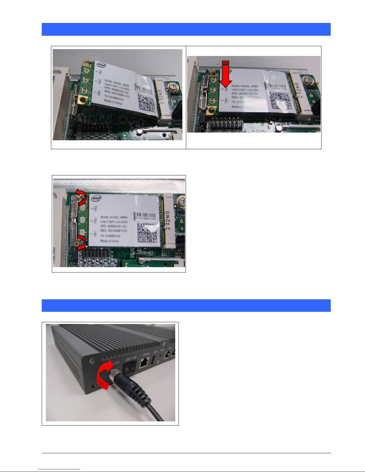
Chapter 9 Installing Mini PCI-e Module
Fig. 9-1 Insert Mini PCI-e module
(Supports USB signal only)
Fig. 9-3 Release two clips to remove module
Fig. 9-2 Push down the module into socket
Chapter 10 Lock Power Connector
Fig. 10-1 Plug power connector into power jack
 Loading...