


CMI222 System Family
Mini-ITX Standard Systems
User’s Manual
Version 1.0
(Aug. 2017)

ii
CMI222 System Family User Manual
Copyright
© 2017 IBASE Technology, Inc. All rights reserved.
No part of this publication may be reproduced, copied, stored in a retrieval system, translated
into any language or transmitted in any form or by any means, electronic, mechanical,
photocopying, or otherwise, without the prior written consent of IBASE Technology, Inc.
(hereinafter referred to as “IBASE”).
Disclaimer
IBASE reserves the right to make changes and improvements to the products described in
this document without prior notice. Every effort has been made to ensure the information in
the document is correct; however, IBASE does not guarantee this document is error-free.
IBASE assumes no liability for incidental or consequential damages arising from
misapplication or inability to use the product or the information contained herein, nor for any
infringements of rights of third parties, which may result from its use.
Trademarks
All the trademarks, registrations and brands mentioned herein are used for identification
purposes only and may be trademarks and/or registered trademarks of their respective
owners.

CMI222 System Family User Manual
iii
Compliance
This product has passed CE tests (pre-scan) for environmental specifications and
limits. This product is in accordance with the directives of the Union European (EU).
If users modify and/or install other devices in this equipment, the CE conformity
declaration may no longer apply.
This product has been tested and found to comply with the limits for a Class B (prescan) device, pursuant to Part 15 of the FCC Rules. These limits are designed to
provide reasonable protection against harmful interference in a residential
installation. This equipment generates, uses and can radiate radio frequency energy
and, if not installed and used in accordance with manufacturer’s instructions, may
cause harmful interference to radio communications.
WEEE
This product must not be disposed of as normal household waste, in
accordance with the EU directive of for waste electrical and electronic
equipment (WEEE - 2012/19/EU). Instead, it should be disposed of by
returning it to a municipal recycling collection point. Check local
regulations for disposal of electronic products.
Green IBASE
This product is compliant with the current RoHS restrictions and
prohibits use of the following substances in concentrations exceeding
0.1% by weight (1000 ppm) except for cadmium, limited to 0.01% by
weight (100 ppm).
• Lead (Pb)
• Mercury (Hg)
• Cadmium (Cd)
• Hexavalent chromium (Cr6+)
• Polybrominated biphenyls (PBB)
• Polybrominated diphenyl ether (PBDE)

iv
CMI222 System Family User Manual
Important Safety Information
Carefully read the precautions before using the device.
Environmental conditions:
• Lay the device horizontally on a stable and solid surface in case the device may
fall, causing serious damage.
• Leave plenty of space around the device and do not block the openings for
ventilation. NEVER DROP OR INSERT ANY OBJECTS OF ANY KIND INTO
THE VENTIILATION OPENINGS.
• Slots and openings on the chassis are for ventilation. Do not block or cover these
openings. Make sure you leave plenty of space around the device for ventilation.
NEVER INSERT OBJECTS OF ANY KIND INTO THE VENTILATIN OPENINGS.
• Use this product in environments with ambient temperatures between 0˚C and
45˚C.
• DO NOT LEAVE THIS DEVICE IN AN ENVIRONMENT WHERE THE
STORAGE TEMPERATURE MAY GO BELOW -20˚C OR ABOVE 80˚C. This
could damage the device. The device must be used in a controlled environment.
Care for your IBASE products:
• Before cleaning the device, turn it off and unplug all cables such as power in case
a small amount of electrical current may still flow.
• Use neutral cleaning agents or diluted alcohol to clean the device chassis with a
cloth. Then wipe the chassis with a dry cloth.
• Vacuum the dust with a computer vacuum cleaner to prevent the air vent or slots
from being clogged.
WARNING
Attention during use:
• Do not use this product near water.
• Do not spill water or any other liquids on your device.
• Do not place heavy objects on the top of the device.
• Operate this device from the type of power indicated on the marking label. If you
are not sure of the type of power available, consult your distributor or local
power company.
• Do not walk on the power cord or allow anything to rest on it.
• If you use an extension cord, make sure that the total ampere rating of the
product plugged into the extension cord does not exceed its limits.
Avoid Disassembly
You are not suggested to disassemble, repair or make any modification to the device.
Disassembly, modification, or any attempt at repair could generate hazards and
cause damage to the device, even bodily injury or property damage, and will void any
warranty.

CMI222 System Family User Manual
v
CAUTION
Danger of explosion if internal lithium-ion battery is replaced by an incorrect type.
Replace only with the same or equivalent type recommended by the manufacturer.
Dispose of used batteries according to the manufacturer’s instructions.
Warranty Policy
• IBASE standard products:
24-month (2-year) warranty from the date of shipment. If the date of shipment
cannot be ascertained, the product serial numbers can be used to determine
the approximate shipping date.
• 3rd-party parts:
12-month (1-year) warranty from delivery for the 3rd-party parts that are not
manufactured by IBASE, such as CPU, memory, HDD, power adapter, panel
and touchscreen.
* PRODUCTS, HOWEVER, THAT FAILS DUE TO MISUSE, ACCIDENT,
IMPROPER INSTALLATION OR UNAUTHORIZED REPAIR SHALL BE
TREATED AS OUT OF WARRANTY AND CUSTOMERS SHALL BE BILLED
FOR REPAIR AND SHIPPING CHARGES.
Technical Support & Services
1. Visit the IBASE website at www.ibase.com.tw to find the latest information about
the product.
2. If you need any further assistance from your distributor or sales representative,
prepare the following information of your product and elaborate upon the
problem.
• Product model name
• Product serial number
• Detailed description of the problem
• The error messages in text or in screenshots if there is any
• The arrangement of the peripherals
• Software in use (such as OS and application software, including the version
numbers)
3. If repair service is required, you can download the RMA form at
http://www.ibase.com.tw/english/Supports/RMAService/. Fill out the form and
contact your distributor or sales representative.

vi
CMI222 System Family User Manual
Table of Contents
Compliance.................................................................................................... iii
Important Safety Information ....................................................................... iv
WARNING ...................................................................................................... iv
CAUTION ........................................................................................................ v
Warranty Policy .............................................................................................. v
Technical Support & Services ...................................................................... v
Chapter 1 General Information ................................................................ 1
1.1 Introduction ............................................................................................. 2
1.2 Features .................................................................................................. 2
1.3 Overview ................................................................................................. 3
1.4 Dimensions ............................................................................................. 8
Chapter 2 Hardware Installation ............................................................. 9
2.1 Essential Installations Before You Begin ............................................... 10
2.1.1 HDD Installation ...................................................................... 10
2.1.2 Memory Installation ................................................................ 11
2.2 Mini-PCIe Cards Installation .................................................................. 11
2.3 WiFi / 3G / 4G Antenna Installation ....................................................... 12
2.4 PCIe (x16) Expansion Card Installation ................................................. 12
2.5 Fan Replacement .................................................................................. 13
2.6 Mounting Brackets Installation .............................................................. 14
2.7 Pinout for GPIO Connectors .................................................................. 16

1
Chapter 1
General Information
The information provided in this chapter includes:
• Features
• Specifications
• Overview
• Dimensions
2
CMI222 System Family User Manual
1.1 Introduction
The CMI222 System Family is a chassis applicable to 4 IBASE Mini-ITX
motherboards – MI811, MI808, MI805 and MI802, and these motherboards
feature iSmart that allows the device capable of auto-scheduling for general
applications and gives energy savings on power. The system family and the
compatible motherboards are listed as below.
Models & Compatible Motherboards:
System Model
CMI222-811
CMI222-808
CMI222-805
CMI222-802
Motherboard
MI811
MI808
MI805
MI802
This system family is able to be operated at the ambient operating temperature
ranging from 0 ~ 45 °C, and even from -20 ~ 80 °C for storage.
1.2 Features
• Expandable Mini-ITX system designed for IBASE Mini-ITX motherboards
• Dual memory slot
• Dual channel for display
• USB 2.0 & USB 3.0 ports
• Dual LAN
• Audio Jacks
• 2.5” HDD and/or mSATA storage
• Expansion slots:
2 x PCI slot (IP245 riser card)
1 x PCI and 1 x PCIe (x1) (IP246 riser card)
• ATX power supply and DC power input 12V

General Information
CMI222 System Family User Manual
3
1
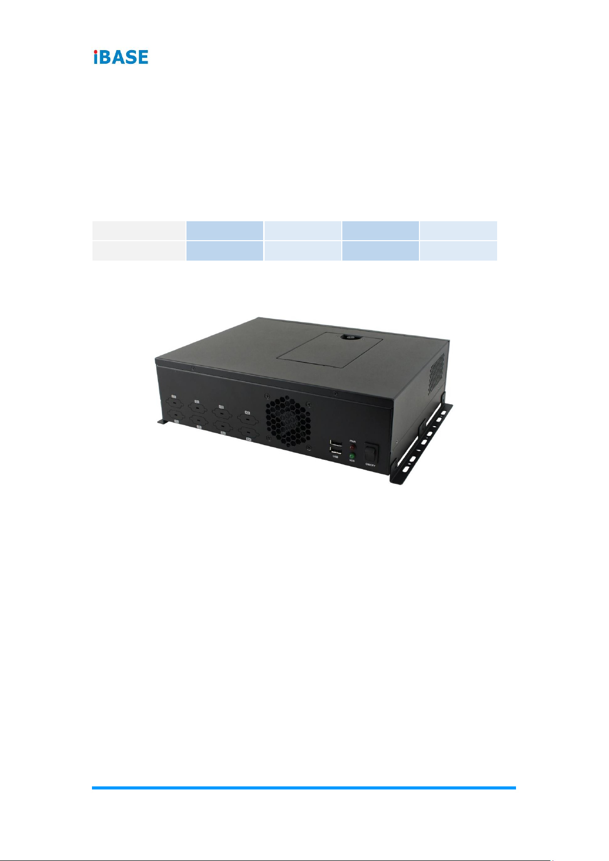
1.3 Overview
Oblique View
No.
Name
No.
Name
1
HDD Tray
4
LED Indicators for HDD &
Power
2
Wall Mount Brackets
5
USB 2.0 Ports
3
Power Switch
6
Reserved COM Ports
4
CMI222 System Family User Manual
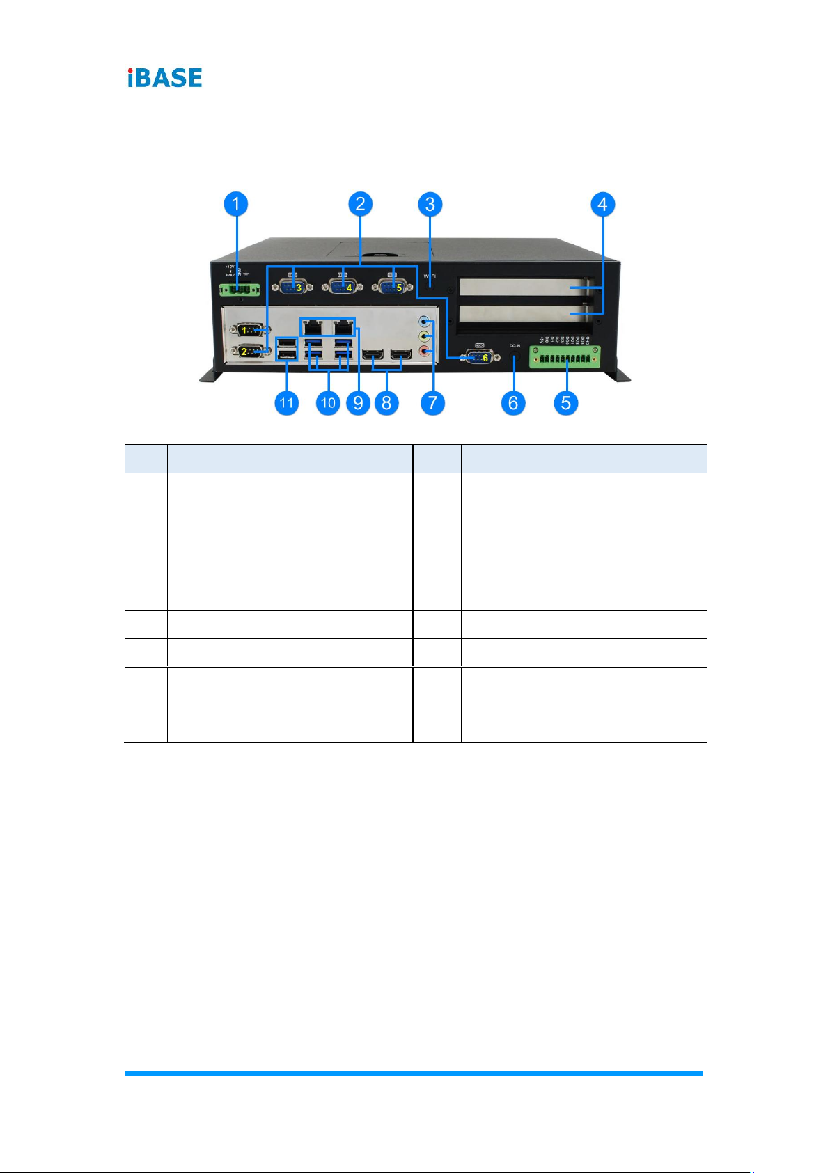
Rear View
CMI222-811:
No.
Name
No.
Name
1
DC Power Connector
7
Audio Jacks
(From top to bottom: Line-In,
Line-Out, Mic-In)
2
COM Ports
(COM1 ~ COM6 marked in
yellow)
8
HDMI Port
3
Antenna Hole
9
GbE LAN Ports
4
Expansion Slots
10
USB 3.0 Ports
5
GPIO Connector
11
USB 2.0 Ports
6
Reserved for DC Power Jack
2.5 mm
General Information
CMI222 System Family User Manual
5
1
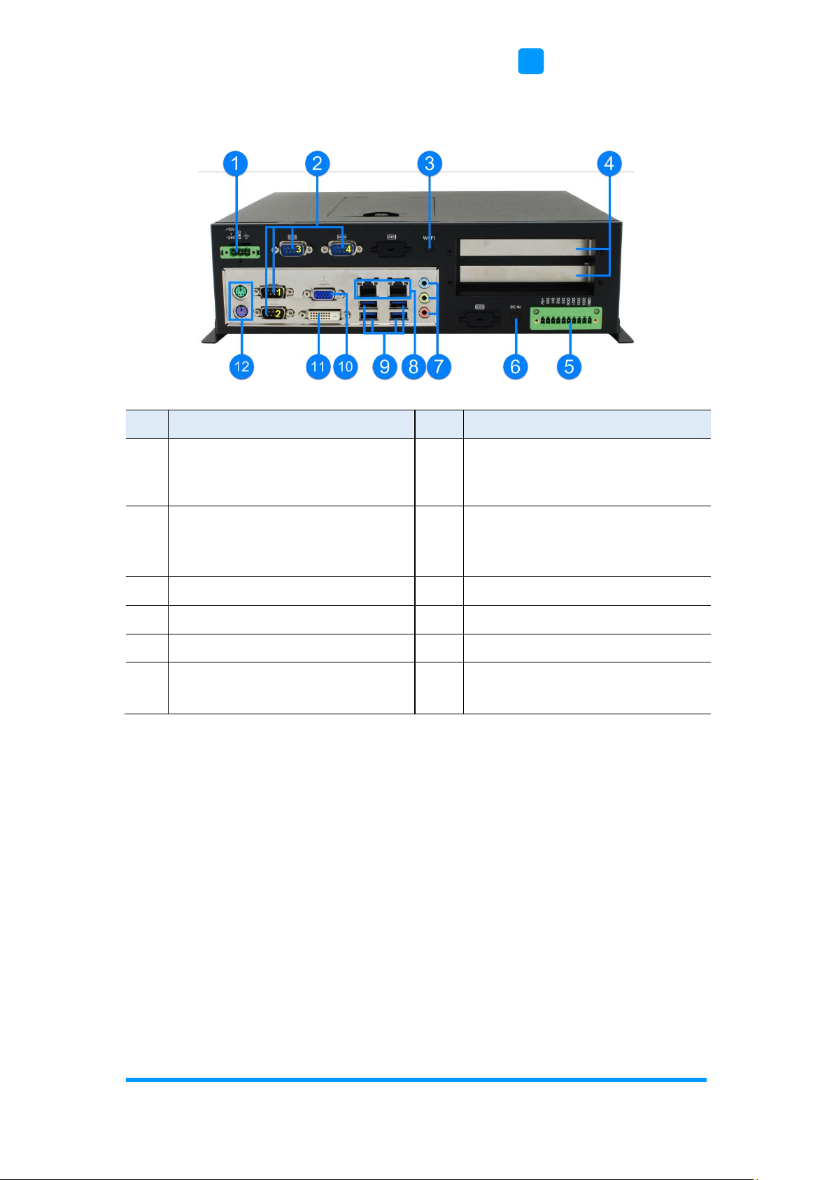
CMI222-808:
No.
Name
No.
Name
1
DC Power Connector
7
Audio Jacks
(From top to bottom: Line-In,
Line-Out, Mic-In)
2
COM Ports
(COM1 ~ COM4 marked in
yellow)
8
GbE LAN Ports
3
Antenna Hole
9
USB 3.0 Ports
4
Expansion Slots
10
VGA Port
5
GPIO Connector
11
DVI-D Port
6
Reserved for DC Power Jack
2.5 mm
12
PS/2 Ports
(From top to bottom: KB, MS)

6
CMI222 System Family User Manual
CMI222-805:
No.
Name
No.
Name
1
DC Power Connector
7
Audio Jacks
(From top to bottom: Line-In,
Line-Out, Mic-In)
2
COM Ports
(COM1 ~ COM6 marked in
yellow)
8
USB 2.0 Ports
3
Antenna Hole
9
GbE LAN Ports
4
Expansion Slots
10
USB 3.0 Ports
5
GPIO Connector
11
VGA Port
6
Reserved for DC Power Jack
2.5 mm
12
DVI-D Port

General Information
CMI222 System Family User Manual
7
1
CMI222-802:
No.
Name
No.
Name
1
DC Power Connector
7
Audio Jacks
(From top to bottom: Line-In,
Line-Out, Mic-In)
2
COM Ports
(COM1 ~ COM6 marked in
yellow)
8
GbE LAN Ports
3
Antenna Hole
9
USB 2.0 Ports
4
Expansion Slots
10
VGA Port
5
GPIO Connector
11
DVI-D Port
6
Reserved for DC Power Jack
2.5 mm
12
PS/2 Ports
(From top to bottom: KB, MS)

8
CMI222 System Family User Manual
1.4 Dimensions
Unit: mm

9
Chapter 2
Hardware Installation
The information provided in this chapter includes:
• Essential installations before you begin: memory, HDD & mini-
PCIe
• Expansion card, antenna, fan, and wall mount installation

10
CMI222 System Family User Manual
2.1 Essential Installations Before You Begin
Release 6 screws to disassemble the device cover for all the installations
except the HDD. After installation, secure the device cover.
2.1.1 HDD Installation
Follow the instructions below for HDD installation or replacement.
1. Loosen the screw indicated below to free up the HDD tray.
2. Loosen another 4 screws to attach your HDD, tighten the screws to fix the
HDD and connect the related cables to the motherboard.
3. Close and secure the tray back.

Appendix
CMI222 System Family User Manual
11
2.1.2 Memory Installation
If you need to replace or install a memory module, follow the instructions
below for installation after disassembling the device cover.
1. Locate the memory slot and align the key of the memory module with that
on the memory slot.
2. Insert the module slantwise and gently push the module straight down
until the clips of the slot close to hold the module in place when the
module touches the bottom of the slot.
.
To remove the module, press the clips outwards with both hands.
2.2 Mini-PCIe Cards Installation
1. Locate the mini-PCIe slot, align the key of the mini-PCIe card to the
interface, and insert the card slantwise.
2. Push the mini-PCIe card down, fix it with one or two flat head screws.
After installation, secure the device cover.

12
CMI222 System Family User Manual
2.3 WiFi / 3G / 4G Antenna Installation
Thread the WiFi / 3G / 4G antenna extension cable through an antenna hole
of the front I/O cover and fasten the antenna as shown below. Then apply
adhesive to the edge of the hex nut behind the front I/O cover to prevent the
extension cable from falling if the cable becomes loose. After installation,
secure the device cover.
1. Thread and fasten the hex nut and the
washer. Then install the antenna.
2. Apply adhesive around here.
Info: The diameter of the nut is around 6.35 mm (0.25”-36UNC).
2.4 PCIe (x16) Expansion Card Installation
If you need to install an expansion card, follow the instructions below for
installation after disassembling the device cover.
1. Release each screw for the expansion filler removal.
2. Install the expansion card(s) and fix with the screw(s) mentioned in Step 1.
After installation, secure the device cover.
Appendix
CMI222 System Family User Manual
13
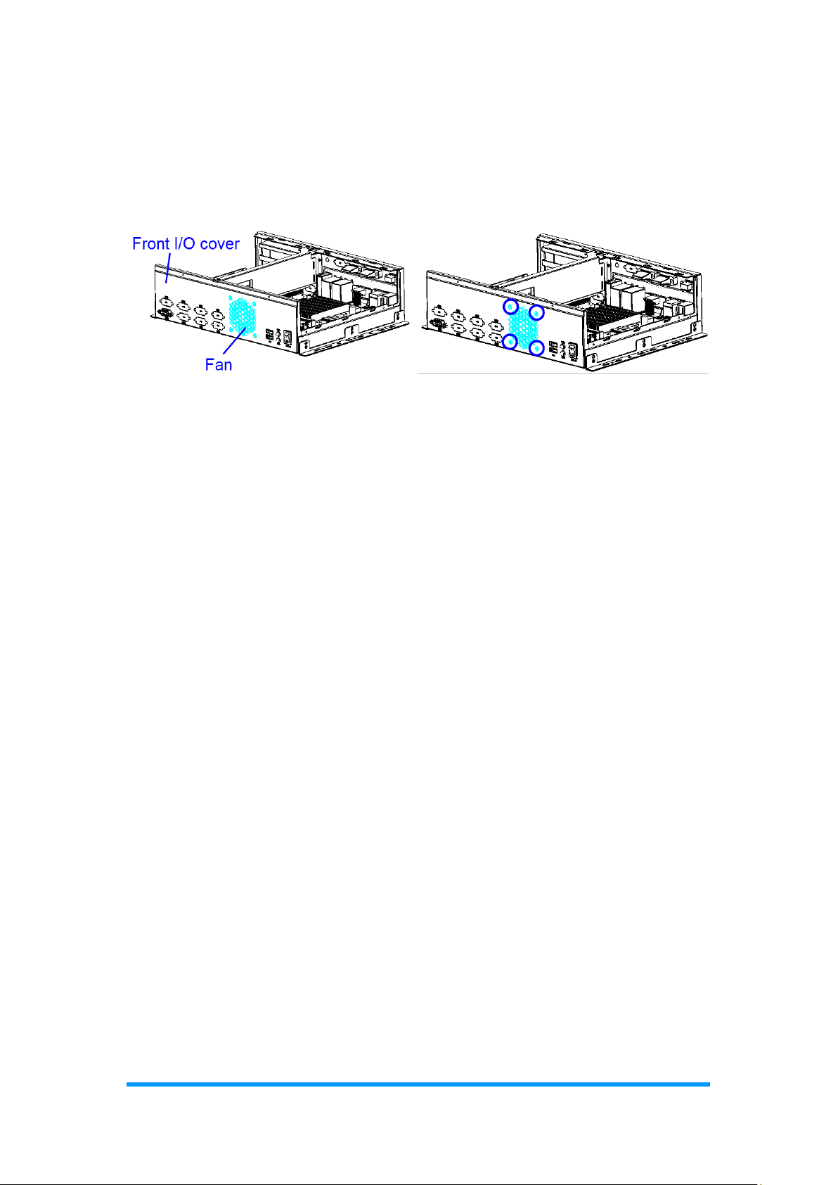
2.5 Fan Replacement
For fan replacement, you also need to disassemble the device cover first.
Then release 4 screws for fan replacement and tighten the screws after
installation.
After installation, secure the device cover.

14
CMI222 System Family User Manual
2.6 Mounting Brackets Installation
Note: Before mounting the system on wall, ensure that you are following all
applicable building and electric codes.
Requirements
When mounting, ensure that you have enough room for power and signal
cable routing. And have good ventilation for power adapter. The method of
mounting must be able to support weight of the CMI222 System plus the
suspend weight of all the cables to be attached to the system. Use the
following methods for mounting your system:
Selecting the Location
Plan the mounting location thoroughly. Locations such as walkway areas,
hallways, and crowded areas are not recommended. Mount the product to a
flat, sturdy, structurally sound column or wall surface.
The best mounting surface is a standard countertop, cabinet, table, or other
structure that is minimally the width and length of the product. This will reduce
the risk that someone may accidentally wall into and damage the product.
Local laws governing the safety of individuals might require this type of
consideration.
Selecting the type of wall construction
1. Mounting on a hollow wall
• Wood surface
Use construction-grade wood and the recommended minimum
thickness is 38 x 25.4 mm (1.5” x 10”).
Note: This method provides the most reliable attachment for the
product with little risk that the product may come loose or
require ongoing maintenance.
• Drywall
Drywall over wood studs is acceptable.
2. Mounting on a solid concrete or brick wall with flat and smooth surface

Appendix
CMI222 System Family User Manual
15
Wall Mount Installation instructions:
1. Attach the mounting brackets to your CMI222 System, and secure with the
supplied six screws as below.
2. Prepare at least four screws (M3, 6 mm) to mount the device on wall .
You can install CMI222 System on plastic (LCD monitor), wood, drywall
surface over studs, or a solid concrete or metal plane directly. The types of
fasteners required are dependent on the type of wall construction.
Fasteners are not supplied in the product package. You will need to prepare
the fasteners. Choose fasteners that are rated either Medium Duty or Heavy
Duty. To assure proper fastener selection and installation, follow the fastener
manufacturer’s recommendations.

16
CMI222 System Family User Manual
2.7 Pinout for GPIO Connectors
• GPIO Connector (10-pin terminal block)
Pin
Assignment
Pin
Assignment
1
5V 6 DO0
2
DI0
7
DO1
3
DI1
8
DO2
4
DI2
9
DO3
5
DI3
10
Ground
11 10
 Loading...