


The information contained in this document has been carefully researched and is, to the best
of our knowledge, accurate. However, we assume no liability for any product failures or
damages, immediate or consequential, resulting from the use of the information provided
herein. Our products are not intended for use in systems in which failures of product could
result in personal injury. All trademarks mentioned herein are property of their resp ective
owners. All specifications are subject to change without notice.
Manual
BYTEM-W071-PC
BYTEM-101-PC
BYTEM-121-PC
iBASE
Our company network supports you worldwide with offices in Germany, Austria,
Switzerland, Great Britain and the USA. For more information please contact:
FORTEC Elektronik AG
Hauptniederlassung
Lechwiesenstr. 9
86899 Landsberg am Lech
Telefon: +49 (0) 8191 91172-0
Telefax: +49 (0) 8191 21770
E-Mail:
sales@fortecag.de
Internet: www.fortecag.de
FORTEC Elektronik AG
Büro West
Hohenstaufenring 55
50674 Köln
Telefon: +49 (0) 221 272 273-0
Telefax: +49 (0) 221 272 273-10
E-Mail:
west@fortecag.de
Internet: www.fortecag.de
FORTEC Elektronik AG
Büro Wien
Nuschinggasse 12
A-1230 Wien
Telefon: +43 1 8673492-0
Telefax: +43 1 8673492-26
E-Mail:
office@fortec.at
Internet: www.fortec.at
ALTRAC AG
(Tochter der FORTEC):
Bahnhofstraße 3
CH-5436 Würenlos
Telefon: +41 (0) 44 7446111
Telefax: +41 (0) 44 7446161
E-Mail:
info@altrac.ch
Internet: www.altrac.ch

www.ibase.com.tw
IBASE Technology Inc.
BYTEM-xx1-PC
User Manual

Copyright © 2013 IBASE Technology Inc. All Rights Reserved. 2
2
BYTEM-xx1-PC User Manual
Revision
Release Date
V1.0
2015/08/11

i
BYTEM-xx1-PC User Manual
Copyright © 2013 IBASE Technology Inc. All Rights Reserved.
No part of this manual, including the products and software described in it, may be
reproduced, transmitted, transcribed, stored in a retrieval system, or translated into
any language in any form or by any means, except documentation kept by the
purchaser for backup purposes, without the express written permission of IBASE
Technology INC. (“IBASE”).
Products and corporate names mentioned in this manual may or may not be
registered trademarks or copyrights of their respective companies, and are used for
identification purposes only. All trademarks are the property of their respective
owners.
Every effort has been made to ensure that the contents of this manual are correct and
up to date. However, the manufacturer makes no guarantee regarding the accuracy of
its contents, and reserves the right to make changes without prior notice.

ii
BYTEM-xx1-PC User Manual
Table of Contents
Safety Information ..................................................................................................iii
Setting up your system ....................................................................................................... iii
Care during use ................................................................................................................... iv
Acknowledgments ............................................................................................................... v
CHAPTER 1 INTRODUCTION .................................................................................... 1
1.1 General Description ....................................................................................................... 1
1.2 System Specification ...................................................................................................... 2
1.2.1 Hardware Specifications ............................................................................................. 2
1.2.2 Dimensions ................................................................................................................. 3
1.2.3 I/O View ...................................................................................................................... 6
1.3 Accessory List ................................................................................................................. 6
1.4 Installation ..................................................................................................................... 7
CHAPTER 2 MOTHERBOARD INTRODUCTION .......................................................... 8
2.1 Introduction ................................................................................................................... 8
2.2 Installing the Memory ................................................................................................. 11
2.3 Setting Jumpers............................................................................................................ 12
CHAPTER 3 BIOS SETUP .........................................................................................28
CHAPTER 4 DRIVERS INSTALLATION .......................................................................42
4.1 Intel Chipset Software Installation Utility ................................................................... 42
4.2 VGA Drivers Installation ............................................................................................... 43
4.3 Realtek High Definition Audio Driver Installation ....................................................... 44
4.4 Intel Trusted Execution Engine Installation ................................................................. 48
Appendix ...............................................................................................................53

Copyright © 2013 IBASE Technology Inc. All Rights Reserved.
iii
IBASE Technology Inc.
Safety Information
Your BYTEM product is designed and tested to meet the latest standards of safety for
information technology equipment. However, to ensure your safety, it is important that
you read the following safety instructions
Setting up your system
Read and follow all instructions in the documentation before you operate your
system.
Do not use this product near water.
Set up the system on a stable surface. Do not secure the system on any unstable
plane.
Do not place this product on an unstable cart, stand, or table. The product may
fall, causing serious damage to the product.
Slots and openings on the chassis are for ventilation. Do not block or cover these
openings. Make sure you leave plenty of space around the system for ventilation.
Never insert objects of any kind into the ventilation openings.
This system should be operated from the type of power indicated on the marking
label. If you are not sure of the type of power available, consult your dealer or
local power company.
Use this product in environments with ambient temperatures between 0˚C and
50˚C.
If you use an extension cord, make sure that the total ampere rating of the
devices plugged into the extension cord does not exceed its ampere rating.
DO NOT LEAVE THIS EQUIPMENT IN AN ENVIRONMENT WHERE THE
STORAGE TEMPERATURE MAY GO BELOW -20° C OR ABOVE 60° C. THIS
COULD DAMAGE THE EQUIPMENT. THE EQUIPMENT SHOULD BE IN A
CONTROLLED ENVIRONMENT.

iv
BYTEM-xx1-PC User Manual
Care during use
Do not walk on the power cord or allow anything to rest on it.
Do not spill water or any other liquids on your system.
When the system is turned off, a small amount of electrical current still flows.
Always unplug all power, and network cables from the power outlets before
cleaning the system.
If you encounter the following technical problems with the product, unplug the
power cord and contact a qualified service technician or your retailer.
The power cord or plug is damaged.
Liquid has been spilled into the system.
The system does not function properly even if you follow the operating
instructions.
The system was dropped or the cabinet is damaged.
Lithium-Ion Battery Warning
CAUTION: Danger of explosion if battery is incorrectly replaced. Replace only with
the same or equivalent type recommended by the manufacturer. Dispose of used
batteries according to the manufacturer’s instructions.
NO DISASSEMBLY
The warranty does not apply to the products that have been disassembled by users.
WARNING
HAZARDOUS MOVING PARTS
KEEP FINGERS AND OTHER BODY PARTS AWAY

Copyright © 2013 IBASE Technology Inc. All Rights Reserved.
v
IBASE Technology Inc.
Acknowledgments
AMI is a registered trademark of AMI Software International, Inc.
AMD and ATI are registered trademarks of AMD Corporation.
Microsoft Windows is a registered trademark of Microsoft Corporation.
FINTEK is a registered trademark of FINTEK Electronics Corporation.
REALTEK is a registered trademark of REALTEK Electronics Corporation.
All other product names or trademarks are properties of their respective owners.


1
BYTEM-xx1-PC User Manual
CHAPTER 1 INTRODUCTION
1.1 General Description
BYTEM, an ALL in ONE Panel PC, utilizes an Intel® Atom™ processor that provides
high computing performance with low power consumption. It is available in 7-inch,
10.1-inch and 12.1-inch sizes.
The fanless BYTEM series operates silently and reliably in harsh environments. It
comes with two SODIMM slots to accommodate up to 8GB of DDR3L 1333MHz
system memory for 10.1-inch, 12.1-inch models and one 2.5” SATA HDD for data
storage. It features two Gigabit Ethernet and one RS-232/422/485 port. (The 7-inch
model supports two COM ports.) The unit is equipped with a front bezel that has
IP65-rated protection.
The BYTEM series supports a wide-range 9V~30V DC power input for 10.1-inch
and 12.1-inch models, using an 84W power adaptor, and 12V DC power input for
7-inch unit with a 60W power adaptor which makes it ideal for factory automation or
any other industrial applications.
BYTEM-W071-PC overview
BYTEM-101/121-PC overview

2
BYTEM-xx1-PC User Manual
1.2 System Specification
1.2.1 Hardware Specifications
Model Name
BYTEM-W071-PC
BYTEM-101-PC
BYTEM-121-PC
System Mainboard
IB897
CPU
Intel® Atom E3815
(Single-Core @ 1.46 GHz)
Intel® Atom E3845 (Quad-Core @ 1.91 GHz)
Chipset
Integrated in Intel® AtomTM SoC
Memory
2x DDR3L-1333 SO-DIMM, up to 4GB, Default 2GB(2GBx1) for BYTEM-W 071-PC
2x DDR3L-1333 SO-DIMM, up to 8GB, Default 4GB(4GBx1) for BYTEM-101/121-PC
I/O Interface
1 x USB 3.0 flag type blue color
1 x USB 2.0 Type A flag type
1 x D-SUB9 RS-232/422/485 COM1
1 x COM2 for BYTEM-W071-PC only
1 x DP port
2 x Gigabit LAN (RJ45)
1 x 3-pin DC power connector (1 x DC power jack for BYTEM-W071-PC)
1 x Power on/off switch, power on LED / HDD LED
Storage
1 x 2.5” half-size SATA HDD with easy accessibility; Default 32G SSD for
BYTEM-W071-PC
1 x 2.5” SATA HDD with easy accessibility; Default 32G SSD
Expansion Slots
None
Power Supply
12V DC input
9~30V wide range DC input
LCD Size
7” TFT LCD
10.1” TFT LCD
12.1” TFT LCD
LCD Color
16.7M
262K
16.7M
LCD Resolution
1024 x 600
1280 x 800
1024 x 768
LCD Brightness
500
350
LCD View Angle
(H°/V°)
150/150
170/170
160/160
LCD Contrast
800:1
Backlight MTBF
50,000 hrs
12,000 hrs
30,000 hrs
Touch Screen
Projected capacitive touch
Construction
Aluminum front bezel and white steel back cover with aluminum heat-sink
Mounting
Panel Mount
VESA 50x50/75x75 mm
VESA 75X75 mm
Dimensions
(W)x(D)x(H) mm
211.5 x 143.5 x 52
285 x 204 x 59.6
317 x 255 x 59.6
Operating
Temperature
-10°C~ 50°C
0°C~ 50°C(With SSD) / 0°C~ 40°C(with HDD)
Storage
Temperature
-30°C ~ 70°C
-20°C ~ 60°C
Relative Humidity
10%~90% (non-condensing)
Protection Class
IP65 front bezel
Certification
CE/FCC Class B
Operating System
Support
Windows 8 32/64bit, Windows 7 Pro for Embedded 64bit, WES7 64bit
‧
This specification is subject to change without prior notice.

Copyright © 2013 IBASE Technology Inc. All Rights Reserved.
3
IBASE Technology Inc.
1.2.2 Dimensions
BYTEM-W071-PC

4
BYTEM-xx1-PC User Manual
BYTEM-101-PC

Copyright © 2013 IBASE Technology Inc. All Rights Reserved.
5
IBASE Technology Inc.
BYTEM-121-PC

6
BYTEM-xx1-PC User Manual
1.2.3 I/O View
BYTEM-W071-PC I/O side
BYTEM-101/121-PC I/O side
1.3 Accessory List
Part No.
Description
Quantity
1
3-pin terminal block for DC in for
BYTEM-101/121-PC
1 pc
2
DVD
1 pc
3
60W Adaptor for BYTEM-W071-PC only
84W Adaptor and power cord (option)
1 pc

Copyright © 2013 IBASE Technology Inc. All Rights Reserved.
7
IBASE Technology Inc.
1.4 Installation
1.4.1 Installing HDD/SSD
1. Loosen the two screws as shown in the picture.
2. Pull out the HDD/SSD bracket and replace the HDD/SSD module.

8
BYTEM-xx1-PC User Manual
CHAPTER 2 MOTHERBOARD INTRODUCTION
2.1 Introduction
IB897 is a 3.5-inch single board computer based on the Intel® AtomTM E3800
series processor. It supports two DDR3L (1.35V) SODIMM sockets for a maximum
memory capacity of 8GB.
IB897 features Intel's 7th generation (Gen 7) graphics engine and has both CRT
and DisplayPort video display interface, as well as 24-bit LVDS dual channel interface
with the use of the NXP PTN3460 device.
Onboard connectivity available includes two SATA II ports, two COM ports, one
USB 3.0 port, four USB2.0 ports, audio, two Mini PCI-e(x1) slots, and Micro SD.
Power input is provided by a +9~+30V DC in connector.
Product Name
IB897
Form Factor
3.5” disk size SBC
SoC Type/Speed
Intel® AtomTM QC E3845 /2MB cache/1.91GHz (IB897-I45&I45P)
Intel® AtomTM DC E3827 /1MB cache/1.75 GHz (IB897-I27&I27P)
Intel® AtomTM SC E3815 /512KB cache/1.46 GHz (IB897-I15& I15P)
Package = FCBGA1170, 25mmx27mm, 22nm,Tj= -40 ゚ C to +110 ゚ C
BIOS
AMI BIOS
Memory
Intel® AtomTM SoC integrated memory controller
Supports DDR3L (1.35V only), Non-ECC memory only
2 x DDR3 SO-DIMM socket [IB897-I45_P/IB897-I27_P], 8GB max.
1 x DDR3 SO-DIMM socket [IB897-I15_P], 4GB max.
VGA
Intel® Gen7 w/4 EUs graphics engines
DisplayPort x 1 [Supports up to 2560x1200@60Hz]
CRT x 1 via pin header [Supports up to 1920x1080@60Hz]
LVDS
24-bit dual channel via NXP PTN3460 thru eDP
(Supports up to1920x1200 @ 60 Hz)
LAN
Intel® I210IT PCIe Gigabit LAN x 2
USB
Intel® AtomTM SoC built-in USB host controller
Supports USB 2.0 x 4 ports; USB 3.0 x 1 port,
extra USB 2.0 x4 ports (Thru SMSC HUB USB2514)

Copyright © 2013 IBASE Technology Inc. All Rights Reserved.
9
IBASE Technology Inc.
Serial ATA
Intel® AtomTM SoC built-in SATA II controller, supports 2 ports
Audio
Intel® AtomTM SoC built-in HD audio controller + Realtek ALC269QHD
Codec w/ class-D speaker amplifier (2.3W per channel @ 5V power supply)
[7mm x 7mm @ 48-QFN]; support 2-channel audio out + amp
LPC I/O
Nuvoton NCT5523D [64-pin LQFP, 7x7x1.4mm]
- COM #1 (RS232/422/485) [EXAR SP339EER1 x 1 for jumper-less]
- COM #2 (RS-232 only)
[Hardware Monitor]: 2x thermal inputs; 2x voltage monitoring
Digital IO
4 in & 4 out
Expansion Slots
Mini PCI-e socket x2 (1xFull-sized+1xHalf-sized,)
**Full length MiniPCIe (1x) supports mSATA**
Edge Connector
DB9 for COM1, DisplayPort, RJ45 x 2 for LAN 1 & 2
USB 2.0 vertical connector x 1, USB 3.0 vertical connector x 1
LED indicators (red+green) x1 for power and HDD status &
power button x 1(IB897-I45/I27/I15)
4-pin header for LED indicator & 2-pin header for power button via cable
(IB897-I45P/I27P/I15P)
Onboard
Header/
Connector
2x8 pin header for CRT; 2x4 pin header for 2x USB 2.0
DF20 socket connector x2 for 24-bit dual channel LVDS
4-pin box header for backlight/brightness control (PWM)
2x6 pin box header for Audio, 4-pin header for speaker
2x5 pin box header for COM2
2x5 pin headers for LPC (80-port card debugging purpose)
Mini PCI-e(1x) connector x2, 5 pins box header for smart battery
SATA connector x2 for SATA device
4-pin power connector (JST type, for SATA device)
2-pin connector for power input, Micro SD slot (type 3.3V)
Watchdog
Yes (256 segments, 0, 1, 2…255 sec/min)
Power Connector
9V ~ 30V DC-in thru onboard 2-pin connector
Others
iSMART 2.0 [Auto-scheduler / Power resume]
OS Support
Windows 8.1 / Embedded; Windows 7 / Embedded, Linux
RoHS / REACH/
CE / FCC
Yes / Yes / Yes / Class B
Operating Temp.
-40 ゚ C to +85 ゚ C
Board Size
102mm x 147mm

10
BYTEM-xx1-PC User Manual
Board Dimensions for [IB897-I45/I27/I15]

Copyright © 2013 IBASE Technology Inc. All Rights Reserved.
11
IBASE Technology Inc.
2.2 Installing the Memory
The IB897 board supports two DDR3L memory sockets for a maximum of 8GB.
Installing and Removing Memory Modules
To install the DDR3 modules, locate the memory slot on the board and perform the
following steps:
1. Hold the DDR3 module so that the key of the DDR3 module aligned with that on
the memory slot.
2. Gently push the DDR3 module in an upright position until the clips of the slot
close to hold the DDR3 module in place when the DDR3 module touches the
bottom of the slot.
3. To remove the DDR3 module, press the clips with both hands.
** Channel-A slot must be installed with memory module for booting up**

12
BYTEM-xx1-PC User Manual
2.3 Setting Jumpers
Jumpers are used on IB897 to select various settings and features according to
your needs and applications. Contact your supplier if you have doubts about the best
configuration for your needs. The following shows the jumpers/connectors on IB897.
Jumper Locations on IB897

Copyright © 2013 IBASE Technology Inc. All Rights Reserved.
13
IBASE Technology Inc.
JP2: LVDS Panel Brightness Control Selection
JP2
Brightness Control
(PWM mode)
Open
3.3V
Close
5V(Default)
J5: LVDS Panel Power Selection
J5
Setting
Panel Voltage
Pin 1-2
Short/Closed
3.3V (default)
Pin 2-3
Short/Closed
5V
1 2
1
3

14
BYTEM-xx1-PC User Manual
JP5: Clear ME Contents
JP5
Setting
Function
Pin 1-2
Short/Closed
Normal
Pin 2-3
Short/Closed
Clear ME Register
JP6: Clear CMOS Contents
JP6
Setting
Function
Pin 1-2
Short/Closed
Normal
Pin 2-3
Short/Closed
Clear CMOS
1 3
1 3

Copyright © 2013 IBASE Technology Inc. All Rights Reserved.
15
IBASE Technology Inc.
Connector Locations on IB897-I45/I27/I15
Bottom side
CN3: USB3.0 Connector
CN4, CN5: Gigabit LAN Connector
CN4: Intel® I210IT Connector
CN5: Intel® I210IT Connector
CN6: USB2.0 Connector
CN7: DP Connector

16
BYTEM-xx1-PC User Manual
CN8: DB9 Connector (COM1)
Signal Name
Pin #
Pin #
Signal Name
DCD, Data carrier detect
1
6
DSR, Data set ready
RXD, Receive data
2
7
RTS, Request to send
TXD, Transmit data
3 8 CTS, Clear to send
DTR, Data terminal ready
4 9 RI, Ring indicator
GND, ground
5
10
Not Used
COM1 is jumper-less for RS-232, RS-422 and RS-485 and is to be configured with BIOS Selection.
Pin #
Signal Name
RS-232
R2-422
RS-485
1
DCD
TX-
DATA- 2 RX
TX+
DATA+
3
TX
RX+
NC
4
DTR
RX-
NC 5 Ground
Ground
Ground
6
DSR
NC
NC 7 RTS
NC
NC 8 CTS
NC
NC
9
RI
NC
NC
10
NC
NC
NC
CN9: Micro SD (3.3V) Connector
SW1: Power Switch [For IB897-I45/I27/I15]

Copyright © 2013 IBASE Technology Inc. All Rights Reserved.
17
IBASE Technology Inc.
LED1:
Power LED and HDD LED Connector [For IB897-I45/I27/I15]
The green LED at the bottom is power LED. The red LED on top is the HDD LED.
Signal Name
Pin #
Pin #
Signal Name
VCC3
1 2 HDD_LED
VCC5
3 4 GND
1 2
3 4

18
BYTEM-xx1-PC User Manual
CN1: SATAII /share mSATA/ Connectors
CN2: SATAII Connectors
SYS_FAN1: SYSTEM Fan Power Connector
Pin #
Signal Name
1
Ground
2
+12V(500mA)
3
Rotation detection
1
3

Copyright © 2013 IBASE Technology Inc. All Rights Reserved.
19
IBASE Technology Inc.
J1: Audio Connector (DF11-12DP-2DSA)
Signal Name
Pin #
Pin #
Signal Name
LINEOUT_R
2 1 LINEOUT_L
Ground
4 3 JD_FRONT
LINEIN_R
6 5 LINEIN_L
Ground
8 7 JD_LINEIN
MIC-R
10 9 MIC_L
Ground
12
11
JD_MIC1
J2: Amplify Connector (JST B4B-PH-K-S )
Pin #
Signal Name
1
OUTL+
2
OUTL-
3
OUTR-
4
OUTR+
J7: DDR3L SO-DIMM(CH-A) Sockets
** Please note CH-A must be installed for booting up**
1 11
2 12
1 4

20
BYTEM-xx1-PC User Manual
J3: DDR3L SO-DIMM(CH-B) Sockets
J4, J6: LVDS Connectors, (DF20G-20DP-1V)
J4: First Channel LVDS
J6: Second Channel LVDS
Signal Name
Pin #
Pin #
Signal Name
TX0N
2 1 TX0P
Ground
4 3 Ground
TX1N
6 5 TX1P
Ground
8 7 Ground
TX2N
10 9 TX2P
Ground
12
11
Ground
CLKN
14
13
CLKP
Ground
16
15
Ground
TX3N
18
17
TX3P
Power(1A)
20
19
Power
20 2
19 1
2
20
1
19

Copyright © 2013 IBASE Technology Inc. All Rights Reserved.
21
IBASE Technology Inc.
J9: MCU Flash Connector (factory use only)
J10: SATA HDD Power Connectors (JST B4B-XH-A)
Pin #
Signal Name
1
+5V(1A)
2
Ground
3
Ground
4
+12V(1A)
4
1
4
1

22
BYTEM-xx1-PC User Manual
J11: Smart Battery (JST B5B-PH-K-S )
Pin #
Signal Name
1
RST#
2
ICHSWI#
3
Ground
4
SMB_DATA
5
SMB_CLK
J12: Mini PCIE Connector (share mSATA)
J13: Mini PCIE Connector (Half Size)
1
5

Copyright © 2013 IBASE Technology Inc. All Rights Reserved.
23
IBASE Technology Inc.
J14: USB 2.0 Connector(DF11-8DP-2DSA)
Signal Name
Pin #
Pin #
Signal Name
Vcc
1
2
Ground
D0-
3
4
D1+
D0+
5
6
D1-
Ground
7
8
Vcc
J15: COM2/RS232 Serial Port(DF11-10DP-2DSA)
Signal Name
Pin #
Pin #
Signal Name
DCD, Data carrier detect
1 2 RXD, Receive data
TXD, Transmit data
3 4 Data terminal ready
GND, ground
5 6 DSR, Data set ready
RTS, Request to send
7 8 CTS, Clear to send
RI, Ring indicator
9
10
Not Used
7
1
8
2
1 9
2 10

24
BYTEM-xx1-PC User Manual
J16: VGA Connector (DF11-16DP-2DSA)
Signal Name
Pin #
Pin #
Signal Name
+5V
2 1 Red
Ground
4 3 Green
N.C
6 5 Blue
DDCDATA
8 7 N.C
H_SYNC
10 9 GND
V_SYNC
12
11
GND
DDCCLK
14
13
GND
N.C.
16
15
GND
J17: Digital I/O (signal level 5V) Connector (2.54mm)
Signal Name
Pin #
Pin #
Signal Name
GND
1 2 VCC (500mA)
OUT3
3 4 OUT1
OUT2
5 6 OUT0
IN3
7 8 IN1
IN2
9
10
IN0
15 1
16 2
2 10
1 9

Copyright © 2013 IBASE Technology Inc. All Rights Reserved.
25
IBASE Technology Inc.
J18: Board Input Power Connector (HK_WAFER396-2S-WV )
Pin #
Signal Name
1
+9V to +30V(10A)
2
GND
J19: Reset Switch (2mm)
Pin #
Signal Name
1
Reset Switch
2
Ground
2
1
2
1

26
BYTEM-xx1-PC User Manual
J20: Power Switch (2mm)
Pin #
Signal Name
1
Power Switch
2
Ground
JP3: LCD Backlight Connector (JST B4B-PH-K-S )
Pin #
Signal Name
1
+12V(1A)
2
Backlight Enable
3
Brightness Control
4
Ground
1 2
4
1

Copyright © 2013 IBASE Technology Inc. All Rights Reserved.
27
IBASE Technology Inc.
JP4: SPI Flash Connector (factory use only)
JP7: Factory use only
JP8: Debug 80 Port Connector (factory use only)
2 10
1 9
1 2
2 10

28
BYTEM-xx1-PC User Manual
CHAPTER 3 BIOS SETUP
3.1 BIOS Introduction
The BIOS (Basic Input/Output System) installed in your computer system’s ROM
supports Intel processors. The BIOS provides critical low-level support for a standard
device such as disk drives, serial ports and parallel ports. It also password protection
as well as special support for detailed fine-tuning of the chipset controlling the entire
system.
3.2 BIOS Setup
The BIOS provides a Setup utility program for specifying the system configurations
and settings. The BIOS ROM of the system stores the Setup utility. When you turn on
the computer, the BIOS is immediately activated. Pressing the <Del> key immediately
allows you to enter the Setup utility. If you are a little bit late pressing the <Del> key,
POST (Power On Self Test) will continue with its test routines, thus preventing you
from invoking the Setup. If you still wish to enter Setup, restart the system by pressing
the ”Reset” button or simultaneously pressing the <Ctrl>, <Alt> and <Delete> keys.
You can also restart by turning the system Off and back On again. The following
message will appear on the screen:
Press <DEL> to Enter Setup
In general, you press the arrow keys to highlight items, <Enter> to select, the <PgUp>
and <PgDn> keys to change entries, <F1> for help and <Esc> to quit.
When you enter the Setup utility, the Main Menu screen will appear on the screen.
The Main Menu allows you to select from various setup functions and exit choices.
Warning:
It is strongly recommended that you avoid making any changes to the
chipset defaults. These defaults have been carefully chosen by both
AMI and your system manufacturer to provide the absolute maximum
performance and reliability. Changing the defaults could cause the
system to become unstable and crash in some cases.

Copyright © 2013 IBASE Technology Inc. All Rights Reserved.
29
IBASE Technology Inc.
3.3 Main Settings
Aptio Setup Utility – Copyright © 2013 American Megatrends, Inc.
Main Advanced Chipset Boot Security Save & Exit
BIOS Information
Choose the system default
language
→ ←
Select Screen
↑↓ Select Item
Enter: Select
+- Change Field
F1: General Help
F2: Previous Values
F3: Optimized Default
F4: Save ESC: Exit
System Language
[English]
System Date
System Time
[Tue 01/20/2009]
[21:52:06]
Access Level
Administrator
System Language
Choose the system default language.
System Date
Set the Date. Use Tab to switch between Data elements.
System Time
Set the Time. Use Tab to switch between Data elements.

30
BYTEM-xx1-PC User Manual
Advanced Settings
This section allows you to configure and improve your system and allows you to set up some system
features according to your preference.
Aptio Setup Utility – Copyright © 2013 American Megatrends, Inc.
Main Advanced Chipset Boot Security Save & Exit
► ACPI Settings
► LVDS Configuration
→ ←
Select Screen
↑↓ Select Item
Enter: Select
+- Change Field
F1: General Help
F2: Previous Values
F3: Optimized Default
F4: Save ESC: Exit
► iSmart Controller
► Super IO Configuration
► H/W Monitor
► CPU Configuration
► PPM Configuration
► IDE Configuration
► SDIO Configuration
ACPI Settings
Aptio Setup Utility
– Copyright © 2013 American Megatrends, Inc.
Main Advanced Chipset Boot Security Save & Exit
ACPI Settings
→ ←
Select Screen
↑↓ Select Item
Enter: Select
+- Change Field
F1: General Help
F2: Previous Values
F3: Optimized Default
F4: Save ESC: Exit
Enable ACPI Auto Configuration
Disabled
Enable Hibernation
Enabled
ACPI Sleep State
S3 only (Suspend to …)
Enabled ACPI Auto Configuration
Enables or Disables BIOS ACPI Auto Configuration.
Enable Hibernation
Enables or Disables System ability to Hibernate (OS/S4 Sleep State). This option may be not effective
with some OS.
ACPI Sleep State
Select ACPI sleep state the system will enter when the SUSPEND button is pressed.

Copyright © 2013 IBASE Technology Inc. All Rights Reserved.
31
IBASE Technology Inc.
LVDS Configuration
Aptio Setup Utility – Copyright © 2013 American Megatrends, Inc.
Main Advanced Chipset Boot Security Save & Exit
Configuration
→ ← Select Screen
↑↓ Select Item
Enter: Select
+- Change Field
F1: General Help
F2: Previous Values
F3: Optimized Default
F4: Save ESC: Exit
Panel Color Depth
LVDS Channel Type
24 BIT
Single
Panel Type
LVDS Backlight Control
1024 x 768
0(Min)
iSmart Controller
Aptio Setup Utility
– Copyright © 2013 American Megatrends, Inc.
Main Advanced Chipset Boot Security Save & Exit
iSmart Controller
→ ← Select Screen
↑↓ Select Item
Enter: Select
+- Change Field
F1: General Help
F2: Previous Values
F3: Optimized Default
F4: Save ESC: Exit
Power-On after Power failure
Schedule Slot 1
Disable
None
Schedule Slot 2
None
Power-On after Power failure
This field sets the system power status whether Disable or Enable when power returns to the system
from a power failure situation.
Schedule Slot 1 / 2
Setup the hour/minute for system power on.

32
BYTEM-xx1-PC User Manual
Super IO Configuration
Aptio Setup Utility – Copyright © 2013 American Megatrends, Inc.
Main Advanced Chipset Boot Security Save & Exit
Super IO Configuration
→ ← Select Screen
↑↓ Select Item
Enter: Select
+- Change Field
F1: General Help
F2: Previous Values
F3: Optimized Default
F4: Save ESC: Exit
► Serial Port 1 Configuration
► Serial Port 2 Configuration
Serial Port 1 Configuration
Set parameters of serial port 1(COMA)
Serial Port 2 Configuration
Set parameters of serial port 2(COMA)

Copyright © 2013 IBASE Technology Inc. All Rights Reserved.
33
IBASE Technology Inc.
H/W Monitor
Aptio Setup Utility – Copyright © 2013 American Megatrends, Inc.
Main Advanced Chipset Boot Security Save & Exit
PC Health Status
→ ← Select Screen
↑↓ Select Item
Enter: Select
+- Change Field
F1: General Help
F2: Previous Values
F3: Optimized Default
F4: Save ESC: Exit
Smart Fan Function
Disabled
SYS temp
+33.0 C
CPU temp
+34.5 C
FAN1 Speed
4066 RPM
Vcore
+1.704 V
+1.35V
+1.544 V
AVCC
+3.360 V
VSB3
VCC3V
+3.344 V
+3.328 V
CPU Shutdown Temperature
Disabled
Smart Fan Function
This field enables or disables the smart fan feature.
Disabled (default)
50 ℃
60 ℃
70 ℃
80 ℃
90 ℃
Shutdown Temperature
This field enables or disables the Shutdown Temperature
Disabled (default)
70 ℃/158 F
75 ℃/167 F
80 ℃/176 F
85 ℃/185 F
90 ℃/194 F
90 ℃/203 F
Temperatures/Voltages
These fields are the parameters of the hardware monitoring function feature of the motherboard. The
values are read-only values as monitored by the system and show the PC health status

34
BYTEM-xx1-PC User Manual
CPU Configuration
This section shows the CPU configuration parameters.
Aptio Setup Utility
– Copyright © 2013 American Megatrends, Inc.
Main Advanced Chipset Boot Security Save & Exit
CPU Configuration
►Socket 0 CPU Information
→ ← Select Screen
↑↓ Select Item
Enter: Select
+- Change Field
F1: General Help
F2: Previous Values
F3: Optimized Default
F4: Save ESC: Exit
CPU Speed
1751 Mhz
64-bit
Supported
Socket 0 CPU Information
Socket specific CPU Information.

Copyright © 2013 IBASE Technology Inc. All Rights Reserved.
35
IBASE Technology Inc.
CPU PPM Configuration
Aptio Setup Utility – Copyright © 2013 American Megatrends, Inc.
Main Advanced Chipset Boot Security Save & Exit
CPU PPM Configuration
→ ← Select Screen
↑↓ Select Item
Enter: Select
+- Change Field
F1: General Help
F2: Previous Values
F3: Optimized Default
F4: Save ESC: Exit
EIST
Enabled
EIST
Enable/Disable Intel SpeedStep.

36
BYTEM-xx1-PC User Manual
IDE Configuration
SATA Devices Configuration.
Aptio Setup Utility
– Copyright © 2013 American Megatrends, Inc.
Main Advanced Chipset Boot Security Save & Exit
IDE Configuration
→ ← Select Screen
↑↓ Select Item
Enter: Select
+- Change Field
F1: General Help
F2: Previous Values
F3: Optimized Default
F4: Save ESC: Exit
Serial-ATA (SATA)
Enabled
SATA Mode
AHCI
Serial-ATA Port 0
Enabled
SATA Port0 HotPlug
Disabled
Serial-ATA Port 1
Enabled
SATA Port1 HotPlug
Disabled
SATA Port0
Not Present
SATA Port1
Not Present
Serial-ATA(SATA)
Enabled / Disabled Serial ATA
SATA Mode
Select IDE / AHCI Mode
Serial–ATA Port 0
Enabled / Disabled Serial Port 0
SATA Port0 HotPlug
Enabled / Disabled SATA Port 0 HotPlug
Serial–ATA Port 1
Enabled / Disabled Serial Port 1
SATA Port1 HotPlug
Enabled / Disabled SATA Port 1 HotPlug

Copyright © 2013 IBASE Technology Inc. All Rights Reserved.
37
IBASE Technology Inc.
SDIO Configuration
Aptio Setup Utility – Copyright © 2013 American Megatrends, Inc.
Main Advanced Chipset Boot Security Save & Exit
→ ← Select Screen
↑↓ Select Item
Enter: Select
+- Change Field
F1: General Help
F2: Previous Values
F3: Optimized Default
F4: Save ESC: Exit
SDIO Access Mode
Auto
SDIO Access Mode
Auto Option: Access SD device in DMA mode if controller supports it. Otherwise, in PIO mode. DMA
options: Access SD device in DMA mode. PIO Option: Access PIO device in DMA

38
BYTEM-xx1-PC User Manual
Chipset Settings
Aptio Setup Utility – Copyright © 2013 American Megatrends, Inc.
Main Advanced Chipset Boot Security Save & Exit
→ ← Select Screen
↑↓ Select Item
Enter: Select
+- Change Field
F1: General Help
F2: Previous Values
F3: Optimized Default
F4: Save ESC: Exit
► North Bridge
North Bridge
Aptio Setup Utility
– Copyright © 2013 American Megatrends, Inc.
Main Advanced Chipset Boot Security Save & Exit
→ ← Select Screen
↑↓ Select Item
Enter: Select
+- Change Field
F1: General Help
F2: Previous Values
F3: Optimized Default
F4: Save ESC: Exit
Memory Information
Total Memory
4096 MB (LPDDR3)
Memory Slot0
4096 MB (LPDDR3)
Memory Slot2
Not Present

Copyright © 2013 IBASE Technology Inc. All Rights Reserved.
39
IBASE Technology Inc.
3.4 Security Settings
This section allows you to configure and improve your system and allows you to set up some
system features according to your preference.
Aptio Setup Utility
– Copyright © 2013 American Megatrends, Inc.
Main Advanced Chipset Boot Security Save & Exit
Password Description
→ ← Select Screen
↑↓ Select Item
Enter: Select
+- Change Field
F1: General Help
F2: Previous Values
F3: Optimized Default
F4: Save ESC: Exit
If ONLY the Administrator’s password is set, then this
only limit access to Setup and is only asked for when
entering Setup.
If ONLY the User’s password is set, then this is a power
on password and must be entered to boot or enter Setup.
In Setup the User will have Administrator rights
The password length must be
in the following range:
Minimum length
3
Maximum length
20
Administrator Password
User Password
Administrator Password
Set Administrator Password.

40
BYTEM-xx1-PC User Manual
Boot Settings
This section allows you to configure the boot settings.
Aptio Setup Utility
– Copyright © 2013 American Megatrends, Inc.
Main Advanced Chipset Boot Security Save & Exit
Boot Configuration
→ ← Select Screen
↑↓ Select Item
Enter: Select
+- Change Field
F1: General Help
F2: Previous Values
F3: Optimized Default
F4: Save ESC: Exit
Setup Prompt Timeout
1
Bootup NumLock State
On
Quiet Boot
Disabled
Fast Boot
Disabled
Boot Option Priorities
Boot Option #1
UEFI:Built-in EFI
Setup Prompt Timeout
Number of seconds to wait for setup activation key.
65535(0xFFFF) means indefinite waiting.
Bootup NumLock State
Select the keyboard NumLock state.
Quiet Boot
Enables or disables Quiet Boot option.
Fast Boot
Enables or disables boot with initialization of a minimal set of devices required to launch active boot
option. Has no effect for BBS boot options.
Boot Option Priorities
Sets the system boot order.

Copyright © 2013 IBASE Technology Inc. All Rights Reserved.
41
IBASE Technology Inc.
Save & Exit Settings
Aptio Setup Utility – Copyright © 2013 American Megatrends, Inc.
Main Advanced Chipset Boot Security Save & Exit
Save Changes and Exit
→ ← Select Screen
↑↓ Select Item
Enter: Select
+- Change Field
F1: General Help
F2: Previous Values
F3: Optimized Default
F4: Save ESC: Exit
Discard Changes and Exit
Save Changes and Reset
Discard Changes and Reset
Save Options
Save Changes
Discard Changes
Restore Defaults
Save as User Defaults
Restore User Defaults
Boot Override
Save Changes and Exit
Exit system setup after saving the changes.
Discard Changes and Exit
Exit system setup without saving any changes.
Save Changes and Reset
Reset the system after saving the changes.
Discard Changes and Reset
Reset system setup without saving any changes.
Save Changes
Save Changes done so far to any of the setup options.
Discard Changes
Discard Changes done so far to any of the setup options.
Restore Defaults
Restore/Load Defaults values for all the setup options.
Save as User Defaults
Save the changes done so far as User Defaults.
Restore User Defaults
Restore the User Defaults to all the setup options.

42
BYTEM-xx1-PC User Manual
CHAPTER 4 DRIVERS INSTALLATION
IMPORTANT NOTE:
After installing your Windows operating system, you must install first the Intel
Chipset Software Installation Utility before proceeding with the drivers installation.
4.1 Intel Chipset Software Installation Utility
The Intel Chipset Drivers should be installed first before the software drivers to enable
Plug & Play INF support for Intel chipset components. Follow the instructions.
1. Insert the DVD that comes with the system. Click System and then
BYTEM-xx1/xx2/xx3 Series
2. Click Intel(R) Chipset Software Installation Utility.
3. When the Welcome screen to the Intel® Chipset Device Software appears,
click Next to continue.
4. Click Yes to accept the software license agreement and proceed with the
installation process.
5. The Setup process is now complete. Click Finish to restart the computer and for
changes to take effect.

Copyright © 2013 IBASE Technology Inc. All Rights Reserved.
43
IBASE Technology Inc.
4.2 VGA Drivers Installation
1. Insert the DVD that comes with the system. Click Intel(R) Baytrail Chipset. Driver
2. When the Welcome screen appears, click Next to continue.
3. Click Yes to accept the license agreement and continue the installation.
4. Setup complete. Click Finish to restart the computer and for changes to take effect.

44
BYTEM-xx1-PC User Manual
4.3 Realtek High Definition Audio Driver Installation
1. Insert the DVD that comes with the system. Click Intel and then Intel(R) Baytrail
Chipset. Click Realtek High Definition Audio Driver.
2. On the Welcome screen, click Next to proceed with the installation.
3. InstallShield Wizard is complete. Click Finish to restart the computer and for
changes to take effect.

Copyright © 2013 IBASE Technology Inc. All Rights Reserved.
45
IBASE Technology Inc.
4.4 I21x Gigabit Network Drivers Installation
1. Insert the DVD that comes with the system. Click Intel(R) I21x Gigabit Network Driver.
2. On the Welcome screen, click Next to proceed with the installation.

46
BYTEM-xx1-PC User Manual
3. Click Next to accept the license agreement.
4. Click Next to accept the setup options.

Copyright © 2013 IBASE Technology Inc. All Rights Reserved.
47
IBASE Technology Inc.
5. Click Install ready to install the program.
6. Install Wizard is complete. Click Finish to restart the computer and for changes to
take effect.
48
BYTEM-xx1-PC User Manual
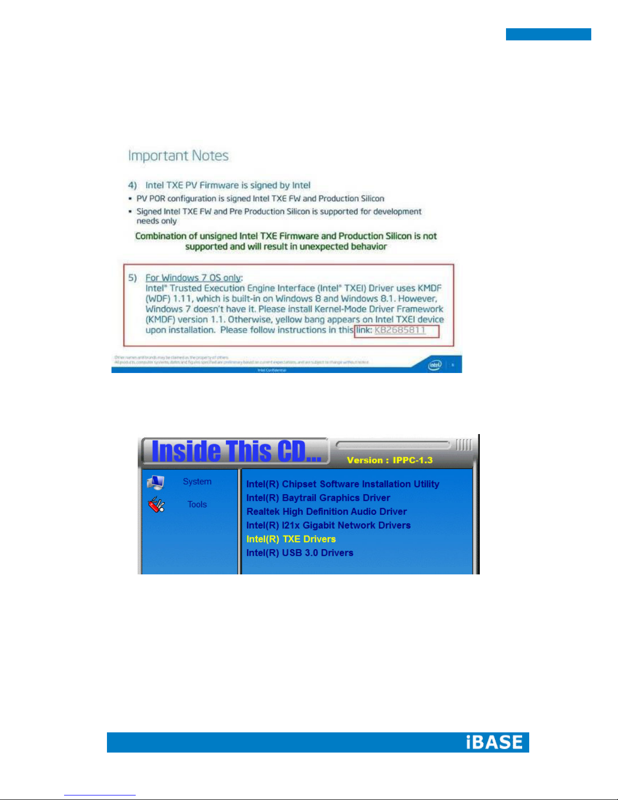
4.5 Intel Trusted Execution Engine Installation
Note :Windows 7 OS only
1. Insert the DVD that comes with the board. Click Intel(R) TXE Driver.

Copyright © 2013 IBASE Technology Inc. All Rights Reserved.
49
IBASE Technology Inc.
2. On the Setup Welcome screen, click Next to proceed with the installation process.
3. Click Next to accept the license agreement.
4. Installation of the Intel Trusted Execution Engine is now complete. Click Finish.

50
BYTEM-xx1-PC User Manual
4.6 Intel USB 3.0 Drivers Installation
1. Insert the DVD that comes with the system. Click Intel(R) USB 3.0 Driver.
2. On the Welcome screen, click Next to proceed.

Copyright © 2013 IBASE Technology Inc. All Rights Reserved.
51
IBASE Technology Inc.
3. Click Yes to accept the license agreement.

52
BYTEM-xx1-PC User Manual
4. Click Next to accept the setup progress.
5. Setup is complete. Click Finish to restart the computer and for changes to take
effect.

Copyright © 2013 IBASE Technology Inc. All Rights Reserved.
53
IBASE Technology Inc.
Appendix
A. I/O Port Address Map
Each peripheral device in the system is assigned a set of I/O port addresses which
also becomes the identity of the device. The following table lists the I/O port
addresses used.
Address
Device Description
0000h-001Fh
Direct memory access controller
0000h-001Fh
PCI bus
0040h-0043h
System timer
0050h-0053h
System timer
0070h-0077h
System CMOS/real time clock
0081h-0091h
Direct memory access controller
0093h-009Fh
Direct memory access controller
00C0h-00DFh
Direct memory access controller
00F0h-00F0h
Numeric data processor
02F8h-02FFh
Communications Port (COM2)
03B0h-03BBh
Intel(R) HD Graphics 4600
03C0h-03DFh
Intel(R) HD Graphics 4600
03F8h-03FFh
Communications Port (COM1)
0D00h-FFFFh
PCI bus
E000h-EFFFh
Intel(R) 8 Series/C220 Series PCI Express Root Port #7 - 8C1C
F000h-F03Fh
Intel(R) HD Graphics 4600
F040h-F05Fh
Intel(R) 8 Series/C220 Series SMBus Controller - 8C22
F060h-F07Fh
Intel(R) 8 Series/C220 Series SATA AHCI Controller - 8C02
F0A0h-F0A3h
Intel(R) 8 Series/C220 Series SATA AHCI Controller - 8C02
F0B0h-F0B7h
Intel(R) 8 Series/C220 Series SATA AHCI Controller - 8C02
F0C0h-F0C3h
Intel(R) 8 Series/C220 Series SATA AHCI Controller - 8C02
F0D0h-F0D7h
Intel(R) 8 Series/C220 Series SATA AHCI Controller - 8C02
F0E0h-F0E7h
Intel(R) Active Management Technology - SOL (COM3)

54
BYTEM-xx1-PC User Manual
B. Interrupt Request Lines (IRQ)
Peripheral devices use interrupt request lines to notify CPU for the service required.
The following table shows the IRQ used by the devices on board.
Level
Function
IRQ0
System Timer
IRQ3
Serial Port #2
IRQ4
Serial Port #1
IRQ 10
Intel(R) 8 Series/C220 Series SMBus Controller - 8C22
IRQ 13
Numeric data processor
IRQ 16
High Definition Audio Controller
IRQ 16
Intel(R) 8 Series/C220 Series USB EHCI #2 - 8C2D
IRQ 16
Intel(R) Management Engine Interface
IRQ 19
Intel(R) 8 Series/C220 Series SATA AHCI Controller - 8C02
IRQ 19
Intel(R) Active Management Technology - SOL (COM3)
IRQ 22
High Definition Audio Controller
IRQ 23
Intel(R) 8 Series/C220 Series USB EHCI #1 - 8C26

Copyright © 2013 IBASE Technology Inc. All Rights Reserved.
55
IBASE Technology Inc.
C. Digital I/O Sample Code
File of the NCT5523D.H
//---------------------------------------------------------------------------
// THIS CODE AND INFORMATION IS PROVIDED "AS IS" WITHOUT WARRANTY OF ANY
// KIND, EITHER EXPRESSED OR IMPLIED, INCLUDING BUT NOT LIMITED TO THE
// IMPLIED WARRANTIES OF MERCHANTABILITY AND/OR FITNESS FOR A PARTICULAR
// PURPOSE.
//---------------------------------------------------------------------------
#ifndef __NCT5523D_H
#define __NCT5523D_H 1
//---------------------------------------------------------------------------
#define NCT5523D_INDEX_PORT (NCT5523D_BASE)
#define NCT5523D_DATA_PORT (NCT5523D_BASE+1)
//---------------------------------------------------------------------------
#define NCT5523D_REG_LD 0x07
//---------------------------------------------------------------------------
#define NCT5523D_UNLOCK 0x87
#define NCT5523D_LOCK 0xAA
//---------------------------------------------------------------------------
unsigned int Init_NCT5523D(void);
void Set_NCT5523D_LD( unsigned char);
void Set_NCT5523D_Reg( unsigned char, unsigned char);
unsigned char Get_NCT5523D_Reg( unsigned char);
//---------------------------------------------------------------------------
#endif //__NCT5523D_H

56
BYTEM-xx1-PC User Manual
File of the MAIN.CPP
//---------------------------------------------------------------------------
// THIS CODE AND INFORMATION IS PROVIDED "AS IS" WITHOUT WARRANTY OF ANY
// KIND, EITHER EXPRESSED OR IMPLIED, INCLUDING BUT NOT LIMITED TO THE
// IMPLIED WARRANTIES OF MERCHANTABILITY AND/OR FITNESS FOR A PARTICULAR
// PURPOSE.
//---------------------------------------------------------------------------
#include <dos.h>
#include <conio.h>
#include <stdio.h>
#include <stdlib.h>
#include "NCT5523D.H"
//---------------------------------------------------------------------------
int main (void);
void Dio5Initial(void);
void Dio5SetOutput(unsigned char);
unsigned char Dio5GetInput(void);
void Dio5SetDirection(unsigned char);
unsigned char Dio5GetDirection(void);
//---------------------------------------------------------------------------
int main (void)
{
char SIO;
SIO = Init_NCT5523D();
if (SIO == 0)
{
printf("Can not detect Nuvoton NCT5523D, program abort.\n");
return(1);
}
Dio5Initial();
//for GPIO20..27
Dio5SetDirection(0x0F); //GP20..23 = input, GP24..27=output
printf("Current DIO direction = 0x%X\n", Dio5GetDirection());

Copyright © 2013 IBASE Technology Inc. All Rights Reserved.
57
IBASE Technology Inc.
printf("Current DIO status = 0x%X\n", Dio5GetInput());
printf("Set DIO output to high\n");
Dio5SetOutput(0x0F);
printf("Set DIO output to low\n");
Dio5SetOutput(0x00);
return 0;
}
//---------------------------------------------------------------------------

58
BYTEM-xx1-PC User Manual
void Dio5Initial(void)
{
unsigned char ucBuf;
ucBuf = Get_NCT5523D_Reg(0x1C);
ucBuf &= ~0x02;
Set_NCT5523D_Reg(0x1C, ucBuf);
Set_NCT5523D_LD(0x07);
//switch to logic device 7 //enable the GP2 group
ucBuf = Get_NCT5523D_Reg(0x30);
ucBuf |= 0x04;
Set_NCT5523D_Reg(0x30, ucBuf);
}
//---------------------------------------------------------------------------
void Dio5SetOutput(unsigned char NewData)
{
Set_NCT5523D_LD(0x07); //switch to logic device 7
Set_NCT5523D_Reg(0xE1, NewData);
}
//---------------------------------------------------------------------------
unsigned char Dio5GetInput(void)
{
unsigned char result;
Set_NCT5523D_LD(0x07); //switch to logic device 7
result = Get_NCT5523D_Reg(0xE1);
return (result);
}
//---------------------------------------------------------------------------
void Dio5SetDirection(unsigned char NewData)
{
//NewData : 1 for input, 0 for output
Set_NCT5523D_LD(0x07); //switch to logic device 7
Set_NCT5523D_Reg(0xE8, NewData);
}
//---------------------------------------------------------------------------
unsigned char Dio5GetDirection(void)

Copyright © 2013 IBASE Technology Inc. All Rights Reserved.
59
IBASE Technology Inc.
{
unsigned char result;
Set_NCT5523D_LD(0x07); //switch to logic device 7
result = Get_NCT5523D_Reg(0xE8);
return (result);
}
//---------------------------------------------------------------------------

60
BYTEM-xx1-PC User Manual
File of the NCT5523D.CPP
//---------------------------------------------------------------------------
// THIS CODE AND INFORMATION IS PROVIDED "AS IS" WITHOUT WARRANTY OF ANY
// KIND, EITHER EXPRESSED OR IMPLIED, INCLUDING BUT NOT LIMITED TO THE
// IMPLIED WARRANTIES OF MERCHANTABILITY AND/OR FITNESS FOR A PARTICULAR
// PURPOSE.
//---------------------------------------------------------------------------
#include "NCT5523D.H"
#include <dos.h>
//---------------------------------------------------------------------------
unsigned int NCT5523D_BASE;
void Unlock_NCT5523D (void);
void Lock_NCT5523D (void);
//---------------------------------------------------------------------------
unsigned int Init_NCT5523D(void)
{
unsigned int result;
unsigned char ucDid;
NCT5523D_BASE = 0x4E;
result = NCT5523D_BASE;
ucDid = Get_NCT5523D_Reg(0x20);
if (ucDid == 0xC4) //NCT5523D??
{ goto Init_Finish; }
NCT5523D_BASE = 0x2E;
result = NCT5523D_BASE;
ucDid = Get_NCT5523D_Reg(0x20);
if (ucDid == 0xC4) //NCT5523D??
{ goto Init_Finish; }
NCT5523D_BASE = 0x00;
result = NCT5523D_BASE;
Init_Finish:
return (result);

Copyright © 2013 IBASE Technology Inc. All Rights Reserved.
61
IBASE Technology Inc.
}
//---------------------------------------------------------------------------
void Unlock_NCT5523D (void)
{
outportb(NCT5523D_INDEX_PORT, NCT5523D_UNLOCK);
outportb(NCT5523D_INDEX_PORT, NCT5523D_UNLOCK);
}
//---------------------------------------------------------------------------
void Lock_NCT5523D (void)
{
outportb(NCT5523D_INDEX_PORT, NCT5523D_LOCK);
}
//---------------------------------------------------------------------------

62
BYTEM-xx1-PC User Manual
void Set_NCT5523D_LD( unsigned char LD)
{
Unlock_NCT5523D();
outportb(NCT5523D_INDEX_PORT, NCT5523D_REG_LD);
outportb(NCT5523D_DATA_PORT, LD);
Lock_NCT5523D();
}
//---------------------------------------------------------------------------
void Set_NCT5523D_Reg( unsigned char REG, unsigned char DATA)
{
Unlock_NCT5523D();
outportb(NCT5523D_INDEX_PORT, REG);
outportb(NCT5523D_DATA_PORT, DATA);
Lock_NCT5523D();
}
//---------------------------------------------------------------------------
unsigned char Get_NCT5523D_Reg(unsigned char REG)
{
unsigned char Result;
Unlock_NCT5523D();
outportb(NCT5523D_INDEX_PORT, REG);
Result = inportb(NCT5523D_DATA_PORT);
Lock_NCT5523D();
return Result;
}
//---------------------------------------------------------------------------

Copyright © 2013 IBASE Technology Inc. All Rights Reserved.
63
IBASE Technology Inc.
D. Watchdog Timer Configuration
The WDT is used to generate a variety of output signals after a user
programmable count. The WDT is suitable for use in the prevention of
system lock-up, such as when software becomes trapped in a deadlock.
Under these sorts of circumstances, the timer will count to zero and the
selected outputs will be driven. Under normal circumstance, the user will
restart the WDT at regular intervals before the timer counts to zero.
SAMPLE CODE:
File of the NCT5523D.H
//---------------------------------------------------------------------------
//
// THIS CODE AND INFORMATION IS PROVIDED "AS IS" WITHOUT WARRANTY OF ANY
// KIND, EITHER EXPRESSED OR IMPLIED, INCLUDING BUT NOT LIMITED TO THE
// IMPLIED WARRANTIES OF MERCHANTABILITY AND/OR FITNESS FOR A PARTICULAR
// PURPOSE.
//
//---------------------------------------------------------------------------
#ifndef __NCT5523D_H
#define __NCT5523D_H 1
//---------------------------------------------------------------------------
#define NCT5523D_INDEX_PORT (NCT5523D_BASE)
#define NCT5523D_DATA_PORT (NCT5523D_BASE+1)
//---------------------------------------------------------------------------
#define NCT5523D_REG_LD 0x07
//---------------------------------------------------------------------------
#define NCT5523D_UNLOCK 0x87
#define NCT5523D_LOCK 0xAA
//---------------------------------------------------------------------------
unsigned int Init_NCT5523D(void);
void Set_NCT5523D_LD( unsigned char);
void Set_NCT5523D_Reg( unsigned char, unsigned char);
unsigned char Get_NCT5523D_Reg( unsigned char);
//---------------------------------------------------------------------------
#endif //__NCT5523D_H

64
BYTEM-xx1-PC User Manual
File of the MAIN.CPP.
//---------------------------------------------------------------------------
//
// THIS CODE AND INFORMATION IS PROVIDED "AS IS" WITHOUT WARRANTY OF ANY
// KIND, EITHER EXPRESSED OR IMPLIED, INCLUDING BUT NOT LIMITED TO THE
// IMPLIED WARRANTIES OF MERCHANTABILITY AND/OR FITNESS FOR A PARTICULAR
// PURPOSE.
//
//---------------------------------------------------------------------------
#include <dos.h>
#include <conio.h>
#include <stdio.h>
#include <stdlib.h>
#include "NCT5523D.H"
//---------------------------------------------------------------------------
int main (void);
void WDTInitial(void);
void WDTEnable(unsigned char);
void WDTDisable(void);
//---------------------------------------------------------------------------
int main (void)
{
char SIO;
SIO = Init_NCT5523D();
if (SIO == 0)
{
printf("Can not detect Nuvoton NCT5523D, program abort.\n");
return(1);
}
WDTInitial();
WDTEnable(10);
WDTDisable();
return 0;

Copyright © 2013 IBASE Technology Inc. All Rights Reserved.
65
IBASE Technology Inc.
}
//---------------------------------------------------------------------------
void WDTInitial(void)
{
unsigned char bBuf;
Set_NCT5523D_LD(0x08); //switch to logic device 8
bBuf = Get_NCT5523D_Reg(0x30);
bBuf &= (~0x01);
Set_NCT5523D_Reg(0x30, bBuf); //Enable WDTO
}
//---------------------------------------------------------------------------
void WDTEnable(unsigned char NewInterval)
{
unsigned char bBuf;
Set_NCT5523D_LD(0x08); //switch to logic device 8
Set_NCT5523D_Reg(0x30, 0x01); //enable timer
bBuf = Get_NCT5523D_Reg(0xF0);
bBuf &= (~0x08);
Set_NCT5523D_Reg(0xF0, bBuf); //count mode is second
Set_NCT5523D_Reg(0xF1, NewInterval); //set timer
}
//---------------------------------------------------------------------------
void WDTDisable(void)
{
Set_NCT5523D_LD(0x08); //switch to logic device 8
Set_NCT5523D_Reg(0xF1, 0x00); //clear watchdog timer
Set_NCT5523D_Reg(0x30, 0x00); //watchdog disabled
}
//---------------------------------------------------------------------------

66
BYTEM-xx1-PC User Manual
File of the NCT5523D.CPP
//---------------------------------------------------------------------------
//
// THIS CODE AND INFORMATION IS PROVIDED "AS IS" WITHOUT WARRANTY OF ANY
// KIND, EITHER EXPRESSED OR IMPLIED, INCLUDING BUT NOT LIMITED TO THE
// IMPLIED WARRANTIES OF MERCHANTABILITY AND/OR FITNESS FOR A PARTICULAR
// PURPOSE.
//
//---------------------------------------------------------------------------
#include "NCT5523D.H"
#include <dos.h>
//---------------------------------------------------------------------------
unsigned int NCT5523D_BASE;
void Unlock_NCT5523D (void);
void Lock_NCT5523D (void);
//---------------------------------------------------------------------------
unsigned int Init_NCT5523D(void)
{
unsigned int result;
unsigned char ucDid;
NCT5523D_BASE = 0x4E;
result = NCT5523D_BASE;
ucDid = Get_NCT5523D_Reg(0x20);
if (ucDid == 0xC4) //NCT5523D??
{ goto Init_Finish; }
NCT5523D_BASE = 0x2E;
result = NCT5523D_BASE;
ucDid = Get_NCT5523D_Reg(0x20);
if (ucDid == 0xC4) //NCT5523D??
{ goto Init_Finish; }
NCT5523D_BASE = 0x00;
result = NCT5523D_BASE;
Init_Finish:

Copyright © 2013 IBASE Technology Inc. All Rights Reserved.
67
IBASE Technology Inc.
return (result);
}
//---------------------------------------------------------------------------
void Unlock_NCT5523D (void)
{
outportb(NCT5523D_INDEX_PORT, NCT5523D_UNLOCK);
outportb(NCT5523D_INDEX_PORT, NCT5523D_UNLOCK);
}
//---------------------------------------------------------------------------
void Lock_NCT5523D (void)
{
outportb(NCT5523D_INDEX_PORT, NCT5523D_LOCK);
}
//---------------------------------------------------------------------------

68
BYTEM-xx1-PC User Manual
void Set_NCT5523D_LD( unsigned char LD)
{
Unlock_NCT5523D();
outportb(NCT5523D_INDEX_PORT, NCT5523D_REG_LD);
outportb(NCT5523D_DATA_PORT, LD);
Lock_NCT5523D();
}
//---------------------------------------------------------------------------
void Set_NCT5523D_Reg( unsigned char REG, unsigned char DATA)
{
Unlock_NCT5523D();
outportb(NCT5523D_INDEX_PORT, REG);
outportb(NCT5523D_DATA_PORT, DATA);
Lock_NCT5523D();
}
//---------------------------------------------------------------------------
unsigned char Get_NCT5523D_Reg(unsigned char REG)
{
unsigned char Result;
Unlock_NCT5523D();
outportb(NCT5523D_INDEX_PORT, REG);
Result = inportb(NCT5523D_DATA_PORT);
Lock_NCT5523D();
return Result;
}
//-----------------------------------------------------------------------

Our company network supports you worldwide with offices in Germany, Austria, Switzerland, Great Britain
and the USA. For more information please contact:
FORTEC Elektronik AG
Hauptniederlassung
Lechwiesenstr. 9
86899 Landsberg am Lech
Telefon: +49 (0) 8191 91172-0
Telefax: +49 (0) 8191 21770
E-Mail:
sales@fortecag.de
Internet: www.fortecag.de
FORTEC Elektronik AG
Büro West
Hohenstaufenring 55
50674 Köln
Telefon: +49 (0) 221 272 273-0
Telefax: +49 (0) 221 272 273-10
E-Mail:
west@fortecag.de
Internet: www.fortecag.de
FORTEC Elektronik AG
Büro Wien
Nuschinggasse 12
A-1230 Wien
Telefon: +43 1 8673492-0
Telefax: +43 1 8673492-26
E-Mail:
office@fortec.at
Internet: www.fortec.at
ALTRAC AG
(Tochter der Fortec AG):
Bahnhofstraße 3
CH-5436 Würenlos
Telefon: +41 (0) 44 7446111
Telefax: +41 (0) 44 7446161
E-Mail:
info@altrac.ch
Internet: www.altrac.ch
Members of the Group:
 Loading...