


ASTUT-152-RE1S
Industrial Panel PC
User’s Manual
Version 1.0
(Sep. 2017)

ii
ASTUT-152-RE1S User Manual
Copyright
© 2017 IBASE Technology, Inc. All rights reserved.
No part of this publication may be reproduced, copied, stored in a retrieval system, translated
into any language or transmitted in any form or by any means, electronic, mechanical,
photocopying, or otherwise, without the prior written consent of IBASE Technology, Inc.
(hereinafter referred to as “IBASE”).
Disclaimer
IBASE reserves the right to make changes and improvements to the products described in
this document without prior notice. Every effort has been made to ensure the information in
the document is correct; however, IBASE does not guarantee this document is error-free.
IBASE assumes no liability for incidental or consequential damages arising from
misapplication or inability to use the product or the information contained herein, nor for any
infringements of rights of third parties, which may result from its use.
Trademarks
All the trademarks, registrations and brands mentioned herein are used for identification
purposes only and may be trademarks and/or registered trademarks of their respective
owners.

ASTUT-152-RE1S User Manual
iii
Compliance
In a domestic environment, this product may cause radio interference in which case
users may be required to take adequate measures.
This product has been tested and found to comply with the limits for a Class B
device, pursuant to Part 15 of the FCC Rules. These limits are designed to provide
reasonable protection against harmful interference in a residential installation. This
equipment generates, uses and can radiate radio frequency energy and, if not
installed and used in accordance with manufacturer’s instructions, may cause
harmful interference to radio communications.
Operation is subject to the following two conditions:
• This product may not cause harmful interference
• This product must accept any interference received including interference that may cause
undesired operation.
However, there is no guarantee that interference will not occur in a particular installation. If
this equipment causes harmful interference to radio or television reception which can be
determined by turning the equipment off and on, you may correct the interference by one or
more of the following measures:
• Reorient or relocate the receiving antenna.
• Increase the separation between the equipment and the receiver.
• Connect the equipment to an outlet on a circuit different from that to which the receiver is
connected.
• Consult the distributor or an experienced radio/TV technician for help.
WEEE
This product must not be disposed of as normal household waste, in
accordance with the EU directive of for waste electrical and electronic
equipment (WEEE - 2012/19/EU). Instead, it should be disposed of by
returning it to a municipal recycling collection point. Check local
regulations for disposal of electronic products.

iv
ASTUT-152-RE1S User Manual
Green IBASE
This product is compliant with the current RoHS restrictions and
prohibits use of the following substances in concentrations exceeding
0.1% by weight (1000 ppm) except for cadmium, limited to 0.01% by
weight (100 ppm).
• Lead (Pb)
• Mercury (Hg)
• Cadmium (Cd)
• Hexavalent chromium (Cr6+)
• Polybrominated biphenyls (PBB)
• Polybrominated diphenyl ether (PBDE)
Important Safety Information
Carefully read the precautions before using the device.
Environmental conditions:
• Lay the device horizontally on a stable and solid surface during installation in
case the device may fall, causing serious damage.
• Leave plenty of space around the device for ventilation.
• Use this product in environments with ambient temperatures between 0˚C and
50˚C.
• DO NOT LEAVE THIS DEVICE IN AN ENVIRONMENT WHERE THE
STORAGE TEMPERATURE MAY BE BELOW -20° C OR ABOVE 60° C. To
prevent from damages, the device must be used in a controlled environment.
• Keep the device away from humidity to avoid fog or condensation from
accumulating on the inner surface of the panel.
Care for your IBASE products:
• Before cleaning the device, turn it off and unplug all cables such as power in case
a small amount of electrical current may still flow.
• Use neutral cleaning agents or diluted alcohol to clean the device chassis with a
cloth. Then wipe the chassis with a dry cloth.
• Vacuum the dust with a computer vacuum cleaner to prevent the air vent or slots
from being clogged.

ASTUT-152-RE1S User Manual
v
WARNING
Attention during use:
• Operate with fingers on the panel. Sharp-pointed articles are prohibited.
• Do not use this product near water.
• Do not spill water or any other liquids on your device.
• Do not place heavy objects on the top of the device.
• Operate this device from the type of power indicated on the marking label. If you
are not sure of the type of power available, consult your distributor or local
power company.
• Do not walk on the power cord or allow anything to rest on it.
• If you use an extension cord, make sure that the total ampere rating of the
product plugged into the extension cord does not exceed its limits.
Avoid Disassembly
You are not suggested to disassemble, repair or make any modification to the device.
Disassembly, modification, or any attempt at repair could generate hazards and
cause damage to the device, even bodily injury or property damage, and will void any
warranty.
Warranty Policy
• IBASE standard products:
24-month (2-year) warranty from the date of shipment. If the date of shipment
cannot be ascertained, the product serial numbers can be used to determine
the approximate shipping date.
• 3rd-party parts:
12-month (1-year) warranty from delivery for the 3rd-party parts that are not
manufactured by IBASE, such as CPU, CPU cooler, memory, storage devices,
power adapter, panel and touchscreen.
* PRODUCTS, HOWEVER, THAT FAIL DUE TO MISUSE, ACCIDENT,
IMPROPER INSTALLATION OR UNAUTHORIZED REPAIR SHALL BE
TREATED AS OUT OF WARRANTY AND CUSTOMERS SHALL BE BILLED
FOR REPAIR AND SHIPPING CHARGES.

vi
ASTUT-152-RE1S User Manual
Technical Support & Services
1. Visit the IBASE website at www.ibase.com.tw to find the latest information about
the product.
2. If you need any further assistance from your distributor or sales representative,
prepare the following information of your product and elaborate upon the
problem.
• Product model name
• Product serial number
• Detailed description of the problem
• The error messages in text or in screenshots if there is any
• The arrangement of the peripherals
• Software in use (such as OS and application software, including the version
numbers)
3. If repair service is required, you can download the RMA form at
http://www.ibase.com.tw/english/Supports/RMAService/. Fill out the form and
contact your distributor or sales representative.

ASTUT-152-RE1S User Manual
vii
Table of Contents
Compliance.................................................................................................... iii
Important Safety Information ....................................................................... iv
WARNING ....................................................................................................... v
Warranty Policy .............................................................................................. v
Technical Support & Services ..................................................................... vi
Chapter 1 General Information ................................................................ 1
1.1 Introduction ............................................................................................. 2
1.2 Features .................................................................................................. 2
1.3 Packing List ............................................................................................ 3
1.4 Optional Accessories .............................................................................. 3
1.5 Specifications .......................................................................................... 4
1.6 Overview ................................................................................................. 6
1.7 Dimensions ............................................................................................. 8
Chapter 2 Hardware Installation & Motherboard Information .............. 9
2.1 Hardware Installation ............................................................................ 10
2.1.1 Memory Installation ................................................................ 10
2.1.2 Pinout for COM1, COM2, & Power Input................................. 11
2.2 Setting the Jumpers .............................................................................. 13
2.2.1 How to Set Jumpers ............................................................... 13
2.3 Jumper & Connector Locations on Motherboard ................................... 14
2.4 Jumpers Quick Reference ..................................................................... 15
2.4.1 COM2 RS-232 Power Selection (JP1).................................. 16
2.4.2 COM1 RS-232/422/485 Power Selection (JP2) .................... 17
2.4.3 LCD Panel Power Selection (J13) ........................................ 18
2.4.4 CMOS Data Clearance (J17) ............................................... 19
2.4.5 ME Register Clearance (J18) ............................................... 20
2.4.6 LVDS / eDP Connector Selection (J12) ................................ 21
2.4.7 PCIe1 Configuration (J7) ...................................................... 22
2.5 Connectors Quick Reference ................................................................ 23
2.5.1 COM Ports (CN1) ................................................................. 24
2.5.2 DVI-I & DVI-D Ports (CN2) ................................................... 25
2.5.3 eDP Connector (CN3) .......................................................... 26

viii
ASTUT-152-RE1S User Manual
2.5.4 Display Port & USB 2.0 Ports (CN4 & CN5) ............................ 27
2.5.5 LAN & USB 3.0 Ports (CN6, CN9) ........................................ 27
2.5.6 SATA III Connector (CN7, CN8, CN13, CN14) ..................... 27
2.5.7 SATA II Connector (CN10, CN11) ........................................ 28
2.5.8 HD Audio Connector (CN12) ................................................ 28
2.5.9 LVDS Connector (JP3, JP4) ................................................. 29
2.5.10 LCD Backlight Connector (JP5)............................................ 30
2.5.11 USB 2.0 Connector (JP6, JP8) ............................................. 30
2.5.12 COM Connector (J1, J2, J3, J4) ........................................... 31
2.5.13 ATX Power Connector (J5) .................................................. 32
2.5.14 ATX 12V Power Connector (J6) ........................................... 33
2.5.15 Digital I/O Connector (J8) ..................................................... 33
2.5.16 DDR3 SO-DIMM Socket (J10, J11) ...................................... 34
2.5.17 Audio Connector for Front Panel (J21) ................................. 34
2.5.18 Front Panel Settings (J22) .................................................... 35
2.5.19 CPU Fan Power Connector (CPU_FAN1) ............................ 35
2.5.20 System Fan Power Connector (SYS_FAN1) ........................ 36
2.5.21 Mini PCIe / mSATA Connector (J14) .................................... 36
2.5.22 Mini PCIe Connector (J15) ................................................... 37
Chapter 3 Driver Installation ................................................................. 38
3.1 Introduction ........................................................................................... 39
3.2 Intel® Chipset Software Installation Utility .............................................. 39
3.3 VGA Driver Installation .......................................................................... 41
3.4 HD Audio Driver Installation .................................................................. 43
3.5 LAN Driver Installation .......................................................................... 44
3.6 Intel® Management Engine (ME) Interface ............................................ 47
3.7 Intel® USB 3.0 Drivers ........................................................................... 49
Chapter 4 BIOS Setup ............................................................................ 51
4.1 Introduction ........................................................................................... 52
4.2 BIOS Setup ........................................................................................... 52
4.3 Main Settings ........................................................................................ 53
4.4 Advanced Settings ................................................................................ 54
4.4.1 PCI Subsystem Settings ......................................................... 55
4.4.2 ACPI Settings ......................................................................... 58
4.4.3 Wake up Event Settings ......................................................... 59
4.4.4 Trusted Computing ................................................................. 59
4.4.5 CPU Configuration .................................................................. 60
4.4.6 SATA Configuration ................................................................ 61
4.4.7 Shutdown Temperature Configuration .................................... 62

ASTUT-152-RE1S User Manual
ix
4.4.8 iSmart Controller ..................................................................... 62
4.4.9 AMT Controller ....................................................................... 63
4.4.10 USB Configuration .................................................................. 64
4.4.11 F8186 Super IO Configuration ................................................ 65
4.4.12 F81866 Hardware Monitor ...................................................... 66
4.5 Chipset Settings .................................................................................... 67
4.5.1 PCH-IO Configuration ............................................................. 67
4.5.2 System Agent (SA) Configuration ........................................... 70
4.6 Boot Settings......................................................................................... 73
4.6.1 CSM Parameters ................................ .................................... 74
4.7 Security Settings ................................................................................... 75
4.8 Save & Exit Settings.............................................................................. 76
Appendix ...................................................................................................... 77
A. I/O Port Address Map ............................................................................ 78
B. Interrupt Request Lines (IRQ) ............................................................... 79
C. Watchdog Timer Configuration .............................................................. 80

1
Chapter 1
General Information
The information provided in this chapter includes:
• Features
• Packing List
• Specifications
• Overview
• Dimensions

2
ASTUT-152-RE1S User Manual
1.1 Introduction
ASTUT-152-RE1S is a 15" all-in-one Panel PC with Riser Card Expansion
carrying the level of IP65 waterproof ingress protection.
12.1” industrial projected touch panel PC that is railway compliant. With Intel®
Atom™ E3845 Quad-Core based processor, the device carries the level of
IP65 ingress protection for the panel to provide good quality of water-tight.
The readability is especially enhanced for operating on rolling shock on the
railway. It is able to be operated at the ambient operating temperature ranging
from -25 to 55 °C, and even from -30 to 70 °C for storage.
1.2 Features
• Intel
®
Core™ i5-4402E Quad-Core processor at 1.6 GHz
• One PCIe 16x expansion slot
• Wide-range 12V ~ 24V DC power input
• IP65 waterproof front panel protection
• Resistive touchscreen

General Information
ASTUT-152-RE1S User Manual
3
1
1.3 Packing List
Your ASTUT-152-RE1S package should include the items listed below. If any
of the items below is missing, contact the distributor or the dealer from whom
you purchased the product.
• ASTUT-152-RE1S x 1
• Mounting Clamp x 10
• Disk x 1
(including chipset drivers and flash memory utility)
1.4 Optional Accessories
IBASE provides optional accessories as follows. Please contact us or your
dealer if you need any.
• Power Adapter (84W, 12V)
• Power Cord (10A, 125V)

4
ASTUT-152-RE1S User Manual
1.5 Specifications
Product Name
ASTUT-152-RE1S
System
Motherboard
MI980VF
Operating
System
• Windows 7 Pro for Embedded
• Windows Embedded Standard 7
CPU
Intel® Core™ i5-4402E Quad-Core (1.6 GHz)
Chipset
Intel® QM87
Memory
2 x DDR3 1600 SO-DIMM 8 GB, expandable up to 16 GB
(1 x 4 GB by default)
Super I/O
Fintek F81866AD-I
LVDS
Dual channel 24-bit
Audio Codec
Realtek ALC662, two-way audio
Membrane
Control
1 x Membrane Control Keypad
(Power, Brightness+, Brightness-, Volume+, Volume-, Power
LED, HDD LED)
Power Supply
12 ~ 24V DC-in
BIOS
AMI BIOS
Watchdog
Watchdog Timer 256 segments, 0, 1, 2…255 sec/min
iSMART
iSMART 2.0 (auto-scheduler / power resume)
Chassis
Black SGCC front bezel and black steel back cover with
aluminum heat-sink
Mounting
VESA 75 x 75 mm (100 x 100 mm)
Dimensions (W
x H x D)
410 x 310 x 84 mm
(16.14” x 12.2” x 3.3”)
Net Weight
7.9 kg (17.4 lb)
Ingress
Protection
IP65 for front panel with panel mount
Certificate
CE, FCC Class B
sPanel
Display Type
15” TFT-LCD
Touch Type
Resistive touch
Point of Touch
1
Resolution
Max. 1024 x 768
Color
Max. 16.2 M

General Information
ASTUT-152-RE1S User Manual
5
1
View Angle
(H/V)
160° / 160°
Light
Transmission
80 %
Luminance
500 cd/m2
Contrast
800:1
Backlight
Lifetime
50000 hrs
Interface
USB
I/O Ports
Power
• 1 x 3-pin DC power connector
• 1 x Power switch
LAN
2 x Gigabit Ethernet (RJ45)
USB
• 4 x USB 3.0
• 2 x USB 2.0
Serial
2 x COM ports:
• COM1 RS-232/422/485
• COM2 RS-232 only
Storage
1 x 2.5” drive bay for SATA II HDD (320 GB)
SATA
2 x SATA II connector
Display
• 1 x DVI-I
• 1 x DVI-D
• 1 x Display Port
Audio
Audio jacks for Microphone input, Line-Out, Line-In
Expansion
• 2 x Mini PCIe (x1) slot (half/full-sized, J15 connector with
USB 2.0 only, J14 connector with USB 2.0 & mSATA)
• 1 x Mini PCIe (x16)
Environment
Temperature
• Operating: 0 ~ 50 °C (32 ~ 122 °F)
• Storage: --20 ~ 60 °C (-4 ~ 140 °F)
Relative
Humidity
10 ~ 90% (non-condensing)
All specifications are subject to change without prior notice.

6
ASTUT-152-RE1S User Manual
1.6 Overview
Oblique View

General Information
ASTUT-152-RE1S User Manual
7
1
I/O View
No.
Name
No.
Name
1
Power Switch
7
USB 2.0 Port
2
DC Power Connector
8
GbE LAN Port
3
COM1 RS-232/422/485 Port
9
Audio Jacks
(From top to bottom: Line-Out,
Line-In, Mic-In)
4
COM2 RS-232 Port
10
2.5” Drive bay
5
DVI-I Port
11
USB 3.0 Port
6
DVI-D Port
12
Display Port

8
ASTUT-152-RE1S User Manual
1.7 Dimensions
Unit: mm

9
Chapter 2
Hardware Installation &
Motherboard Information
The information provided in this chapter includes:
• Memory installation and membrane keypad extension
• Information and locations of connectors

10
ASTUT-152-RE1S User Manual
2.1 Hardware Installation
Avoid Disassembly: You are not suggested to disassemble, repair or make any
modification to the device. Disassembly, modification, or any attempt at repair could
generate hazards and cause damage to the device, even bodily injury or property
damage, and will void any warranty. If you need to make any change to the
device, be sure to have qualified engineers or technicians for disassembly or
installation.
2.1.1 Memory Installation
There are two SO-DIMM DDR3L memory slots inside ASTUT-152-RE1S and
the maximum memory supported is 8 GB.
The ASTUT-152-RE1S supports two SO- DIMM DDR3L memory slots for a
maximum total memory of 8GB. To install the modules, locate the memory
slot on the board and perform the following steps:
1. Align the key of the memory module with that on the memory slot and
insertl the module slantwise.
2. Gently push the module in an upright position until the clips of the slot
close to hold the module in place when the module touches the bottom of
the slot.
To remove the module, press the clips outwards with both hands.

Motherboard Information
ASTUT-152-RE1S User Manual
11
2
2.1.2 Pinout for COM1, COM2, & Power Input
• Power Input (3-pin terminal block)
Pin
Assignment
Pin
Assignment
1
12 ~ 24V
3
DC_IN
2
Frame Ground
• COM1 RS232/422/485 Port
COM 1 is jumperless for RS-232/422/485 selection and configurable in BIOS.
Pin
Assignment
Pin
Assignment
1
DCD, Data carrier detect
6
DSR, Data set ready
2
RXD, Receive data
7
RTS, Request to send
3
TXD, Transmit data
8
CTS, Clear to send
4
DTR, Data terminal ready
9
RI, Ring indicator
5
Ground
Pin
Assignment
RS-232
RS-422
RS-485
1
DCD
TX-
DATA-
2
RX
TX+
DATA+
3
TX
RX+
NC
4
DTR
RX-
NC
5
Ground
Ground
Ground
6
DSR
NC
NC
7
RTS
NC
NC
8
CTS
NC
NC
9
RI
NC
NC
3 1
1
6
5
9

12
ASTUT-152-RE1S User Manual
• COM2 RS-232 Port
Pin
Assignment
Pin
Assignment
1
DCD, Data carrier detect
6
DSR, Data set ready
2
RXD, Receive data
7
RTS, Request to send
3
TXD, Transmit data
8
CTS, Clear to send
4
DTR, Data terminal ready
9
RI, Ring indicator
5
Ground
1
6
5
9
Motherboard Information
ASTUT-152-RE1S User Manual
13
2
2.2 Setting the Jumpers
Set up and configure your ASTUT-152-RE1S by using jumpers for various
settings and features according to your needs and applications. Contact your
supplier if you have doubts about the best configuration for your use.
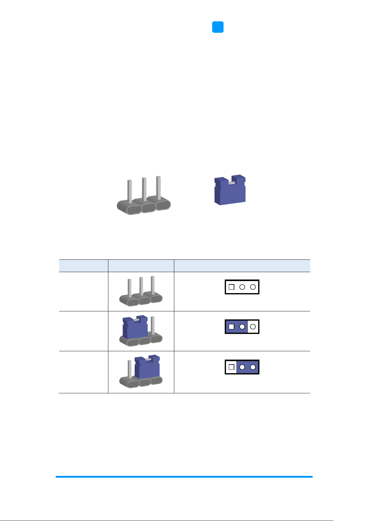
2.2.1 How to Set Jumpers
Jumpers are short-length conductors consisting of several metal pins with a
non-conductive base mounted on the circuit board. Jumper caps are used to
have the functions and features enabled or disabled. If a jumper has 3 pins,
you can connect either PIN1 to PIN2 or PIN2 to PIN3 by shorting.
A 3-pin jumper
A jumper cap
Refer to the illustration below to set jumpers.
Pin closed
Oblique view
Schematic illustration in the manual
Open
1-2
2-3
When two pins of a jumper are encased in a jumper cap, this jumper is
closed, i.e. turned On.
When a jumper cap is removed from two jumper pins, this jumper is open, i.e.
turned Off.
Pin# 1
2
3
1 2 3
1 2 3
1 2 3
14
ASTUT-152-RE1S User Manual
2.3 Jumper & Connector Locations on Motherboard
Motherboard: MI980VF
MI980VF - top
CN8
CN7
BZ1
PCIE1
JP9
JP7
J17
J16
J18
JP5
JP4
JP3
JP2
JP1
J14
J12
J13
J8
J1
J2
J3
J4
J5
J7
J10
J11
CPU_FAN1
SYS_FAN1
J6
J15
CN12
CN3
CN2
CN4 & CN5 CN6 CN9
CN1
J20
J21
JP8
JP6
J22
CN11
CN10
CN14
CN13
Battery
1
1
1
1
10
11
20
1
1
1 2
109
2
2
109
109
9
1
3
2
6
1
2
1
5
6
1
9
1
1
1 19
2
2
1
20
1
1
Intel®4th Gen.
CoreTMi7/i5/
i3/Celeron
®
QC/DC
Intel
®
QM87
1
10
1
9
1
7878
1
1
1
9
12
7
1

Motherboard Information
ASTUT-152-RE1S User Manual
15
2
2.4 Jumpers Quick Reference
Function
Connector Name
Page
COM2 RS-232 Power Selection
JP1
16
COM1 RS-232/422/485 Power Selection
JP2
17
LCD Panel Power Selection
J13
18
CMOS Data Clearance
J17
19
ME Register Clearance
J18
20
LVDS / eDP Connector Selection
J12
21
PCIe1 Configuration
J7
22
Factory User Only
J16
--

16
ASTUT-152-RE1S User Manual
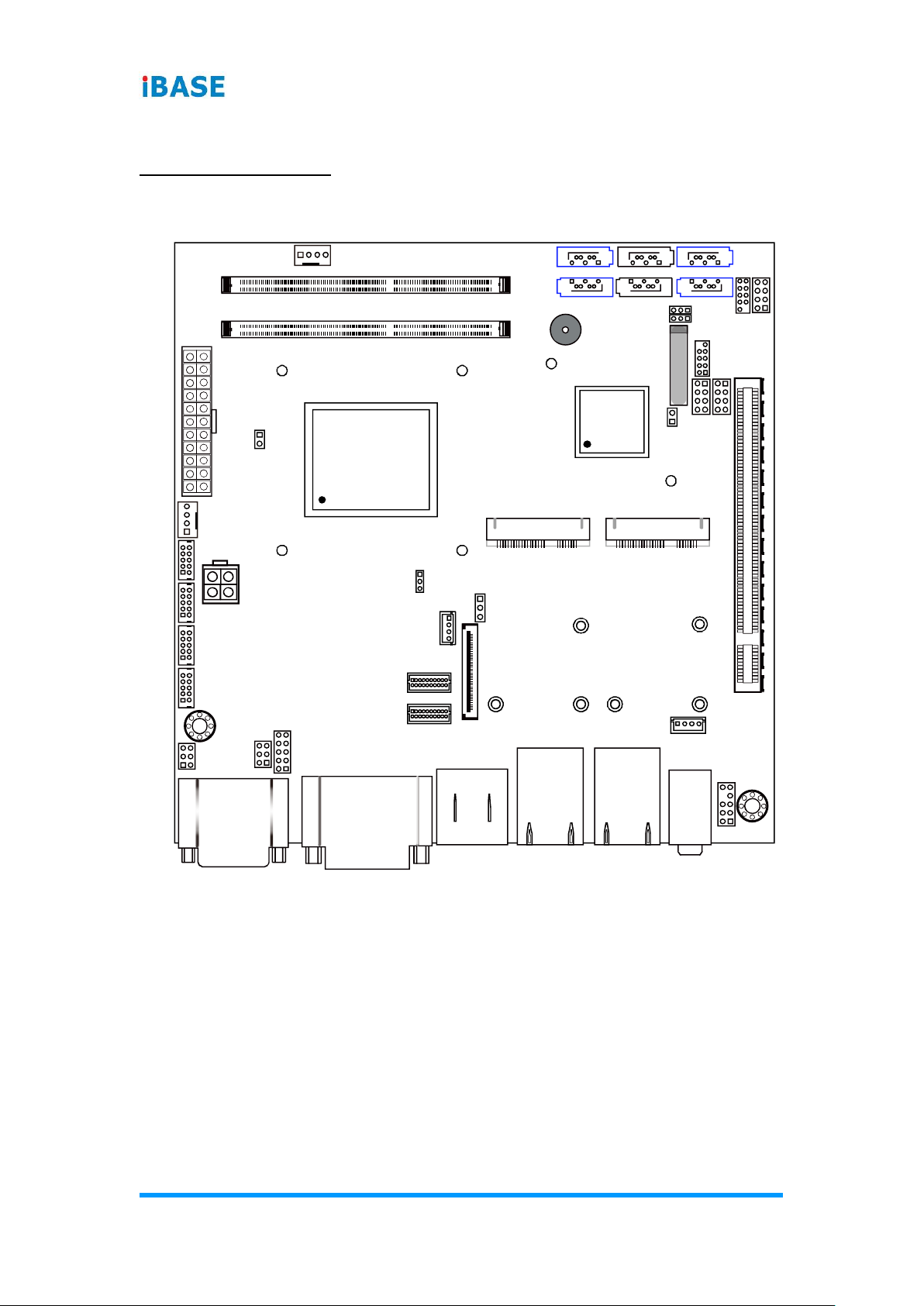
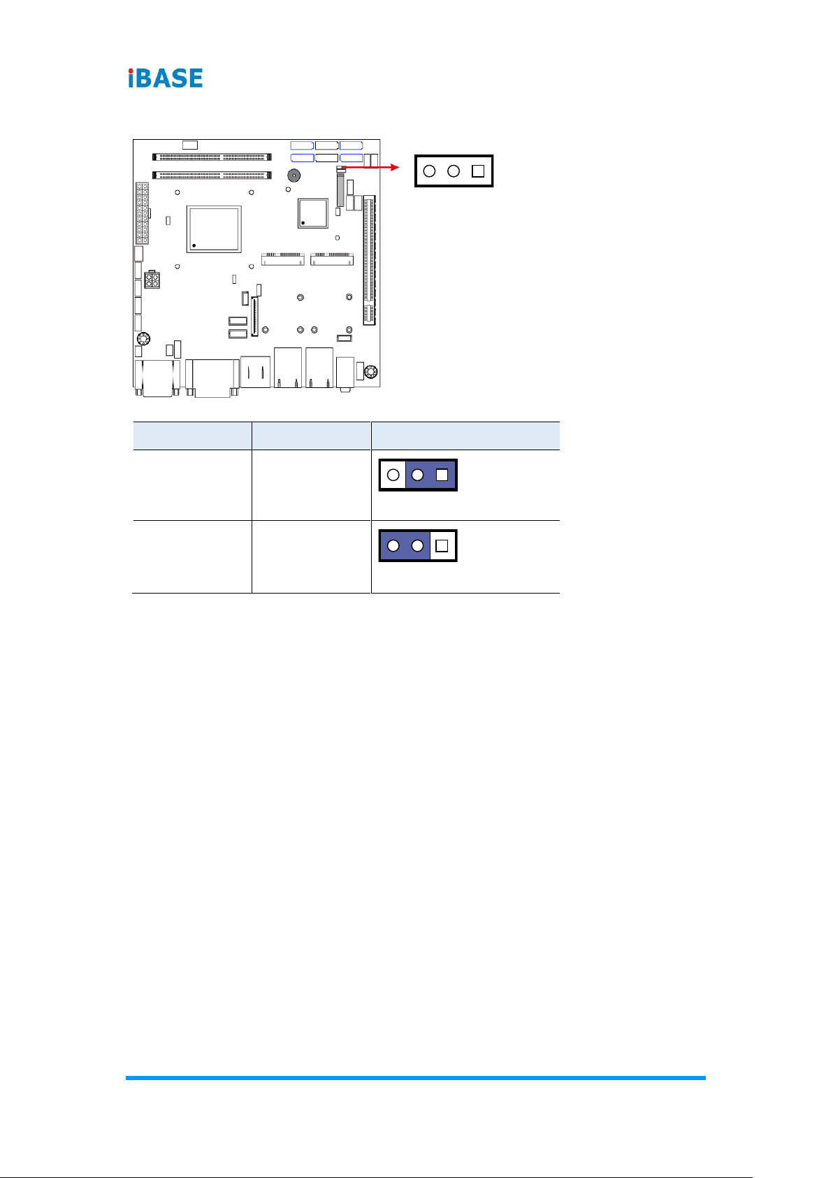
2.4.1 COM2 RS-232 Power Selection (JP1)
Function
Pin closed
Illustration
12V
1-3
RI
(default)
3-4
5V
3-5
12
56
12
56
12
56
12
56
Motherboard Information
ASTUT-152-RE1S User Manual
17
2
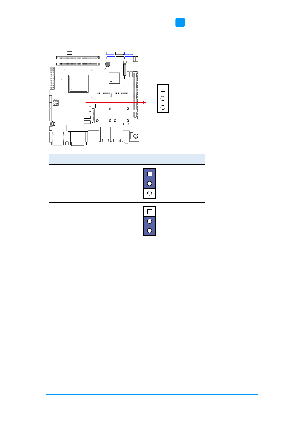
2.4.2 COM1 RS-232/422/485 Power Selection (JP2)
Function
Pin closed
Illustration
12V
1-3
RI
(default)
3-4
5V
3-5
12
56
12
56
12
56
12
56
18
ASTUT-152-RE1S User Manual
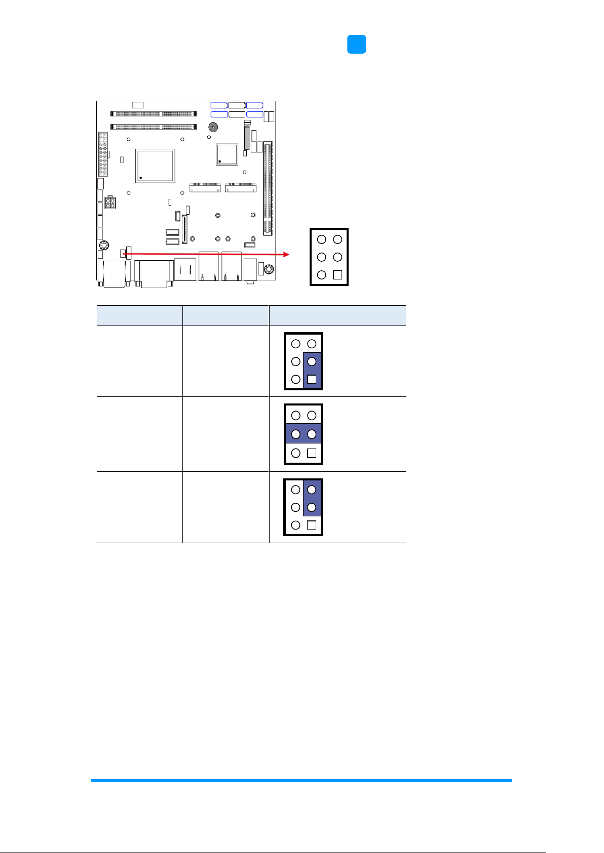
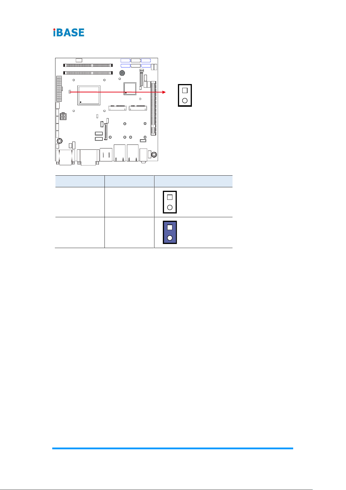
2.4.3 LCD Panel Power Selection (J13)
Function
Pin closed
Illustration
3.3V
(default)
1-2
5V
2-3
1
1
1

Motherboard Information
ASTUT-152-RE1S User Manual
19
2
2.4.4 CMOS Data Clearance (J17)
Function
Pin closed
Illustration
Normal
(default)
1-2
Clear CMOS
2-3
1
1
1
20
ASTUT-152-RE1S User Manual
2.4.5 ME Register Clearance (J18)
Function
Pin closed
Illustration
Normal
(default)
1-2
Clear ME
Register
2-3
1
1
1
Motherboard Information
ASTUT-152-RE1S User Manual
21
2
2.4.6 LVDS / eDP Connector Selection (J12)
Function
Pin closed
Illustration
eDP
Connector
1-2
LVDS
(default)
2-3
1
1
1
22
ASTUT-152-RE1S User Manual
2.4.7 PCIe1 Configuration (J7)
Function
Pin closed
Illustration
PCIe (x16)
(default)
Open
2 x PCIe (x8)
Close
1
1
1

Motherboard Information
ASTUT-152-RE1S User Manual
23
2
2.5 Connectors Quick Reference
Function
Connector Name
Page
COM Ports
CN1
24
DVI-I & DVI-D Ports
CN2
25
eDP Connector
CN3
26
Display Port & USB 2.0 Ports
CN4 & CN5
27
LAN (GbE) & USB 3.0 Ports
CN6, CN9
27
SATA III Connector
CN7, CN8, CN13, CN14
27
SATA II Connector
CN10, CN11
28
HD Audio Connector
CN12
28
LVDS Connector
JP3, JP4
29
LCD Backlight Connector
JP5
30
USB 2.0 Connector
JP6, JP8
30
COM Connector
J1, J2, J3, J4
31
ATX Power Connector
J5
32
ATX 12V Power Connector
J6
33
DDR3 SO-DIMM Socket
J10, J11
34
Audio Connector for Front Panel
J21
34
Front Panel Settings
J22
35
CPU Fan Power Connector
CPU_FAN1
35
System Fan Power Connector
SYS_FAN1
36
Mini PCIe / mSATA Connector
(shared with CN7)
J14
36
Mini PCIe Connector
J15
37
Factory Use Only
JP7, JP9
--

24
ASTUT-152-RE1S User Manual
2.5.1 COM Ports (CN1)
COM1: RS-232/422/485
COM2: RS-232 only
COM 1 is jumperless for RS-232/422/485 selection and configurable in BIOS.
Pin
Assignment
Pin
Assignment
1
DCD, Data carrier detect
6
DSR, Data set ready
2
RXD, Receive data
7
RTS, Request to send
3
TXD, Transmit data
8
CTS, Clear to send
4
DTR, Data terminal ready
9
RI, Ring indicator
5
Ground
Pin
Assignment
RS-232
RS-422
RS-485
1
DCD
TX-
DATA-
2
RX
TX+
DATA+
3
TX
RX+
NC
4
DTR
RX-
NC
5
Ground
Ground
Ground
6
DSR
NC
NC
7
RTS
NC
NC
8
CTS
NC
NC
9
RI
NC
NC
1
6
5
9
1
6
5
9

Motherboard Information
ASTUT-152-RE1S User Manual
25
2
COM2 is RS-232 only.
Pin
Assignment
Pin
Assignment
1
DCD, Data carrier detect
6
DSR, Data set ready
2
RXD, Receive data
7
RTS, Request to send
3
TXD, Transmit data
8
CTS, Clear to send
4
DTR, Data terminal ready
9
RI, Ring indicator
5
Ground
2.5.2 DVI-I & DVI-D Ports (CN2)

26
ASTUT-152-RE1S User Manual
2.5.3 eDP Connector (CN3)
Pin
Assigment
Pin
Assigment
1
3.3V
23
TXN0
2
3.3V
24
TXP0
3
3.3V
25
GND
4
3.3V
26
AUXP
5
3.3V
27
AUXN
6
GND
28
NC
7
GND
29
VCC3
8
GND
30
NC
9
GND
31
VCC12
10
HPD
32
NC
11
NC
33
GND
12
NC
34
VCC5
13
GND
35
NC
14
NC
36
Brightness
15
NC
37
BKLT_EN
16
GND
38
VCC12
17
NC
39
VCC3
18
NC
40
GND
19
GND
41
SMB_THRM_CLK
20
TXN1
42
SMB_THRM_DATA
21
TXP1
43
NC
22
GND
44
NC

Motherboard Information
ASTUT-152-RE1S User Manual
27
2
2.5.4 Display Port & USB 2.0 Ports (CN4 & CN5)
2.5.5 LAN & USB 3.0 Ports (CN6, CN9)
2.5.6 SATA III Connector (CN7, CN8, CN13, CN14)

28
ASTUT-152-RE1S User Manual
2.5.7 SATA II Connector (CN10, CN11)
2.5.8 HD Audio Connector (CN12)
Motherboard Information
ASTUT-152-RE1S User Manual
29
2
2.5.9 LVDS Connector (JP3, JP4)
JP3: 2nd channel
JP4: 1st channel
Pin
Assigment
Pin
Assigment
1
TX0P
2
TX0N
3
Ground
4
Ground
5
TX1P
6
TX1N
7
Ground
8
Ground
9
TX2P
10
TX2N
11
Ground
12
Ground
13
CLKP
14
CLKN
15
Ground
16
Ground
17
TX3P
18
TX3N
19
Power
20
Power
1
2
19
20
1
2
19
20

30
ASTUT-152-RE1S User Manual
2.5.10 LCD Backlight Connector (JP5)
Pin
Assigment
Pin
Assigment
1
+12V
3
Brightness Control
2
Backlight Enable
4
Ground
2.5.11 USB 2.0 Connector (JP6, JP8)
Pin
Assigment
Pin
Assigment
1
Vcc
2
Ground
3
D0-
4
D1+
5
D0+
6
D1-
7
Ground
8
Vcc
1
7
8
2
1

Motherboard Information
ASTUT-152-RE1S User Manual
31
2
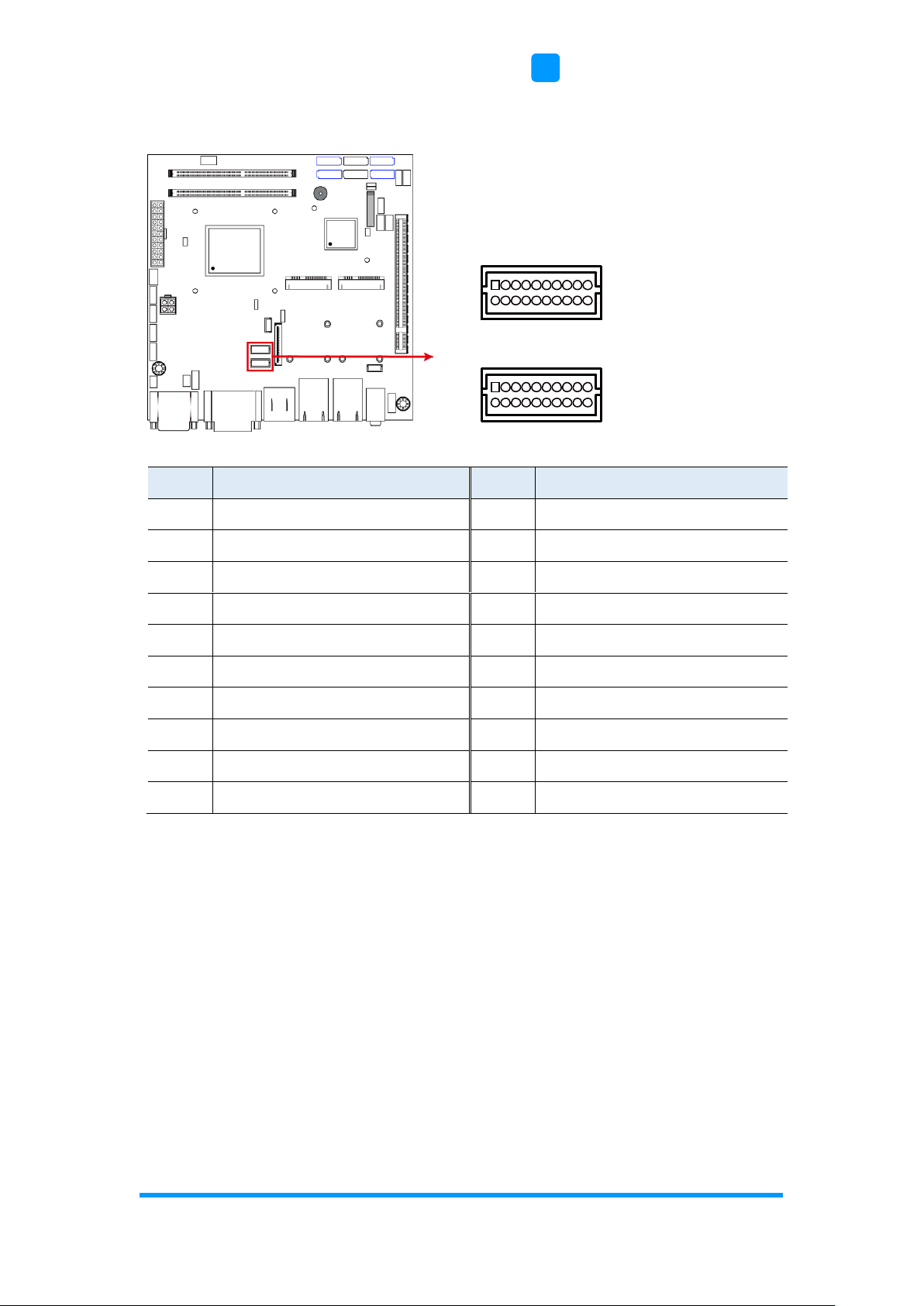
2.5.12 COM Connector (J1, J2, J3, J4)
Pin
Assigment
Pin
Assigment
1
DCD#
2
SIN#
3
SOUT
4
DTR#
5
GND
6
DSR#
7
RTS#
8
CTS#
9
RI#
10
KEY
10
2
9
1

32
ASTUT-152-RE1S User Manual
2.5.13 ATX Power Connector (J5)
Pin
Assigment
Pin
Assigment
1
3.3V
11
3.3V
2
3.3V
12
-12V
3
Ground
13
Ground
4
+5V
14
PS-ON
5
Ground
15
Ground
6
+5V
16
Ground
7
Ground
17
Ground
8
Power good
18
-5V
9
5VSB
19
+5V
10
+12V
20
+5V
Motherboard Information
ASTUT-152-RE1S User Manual
33
2
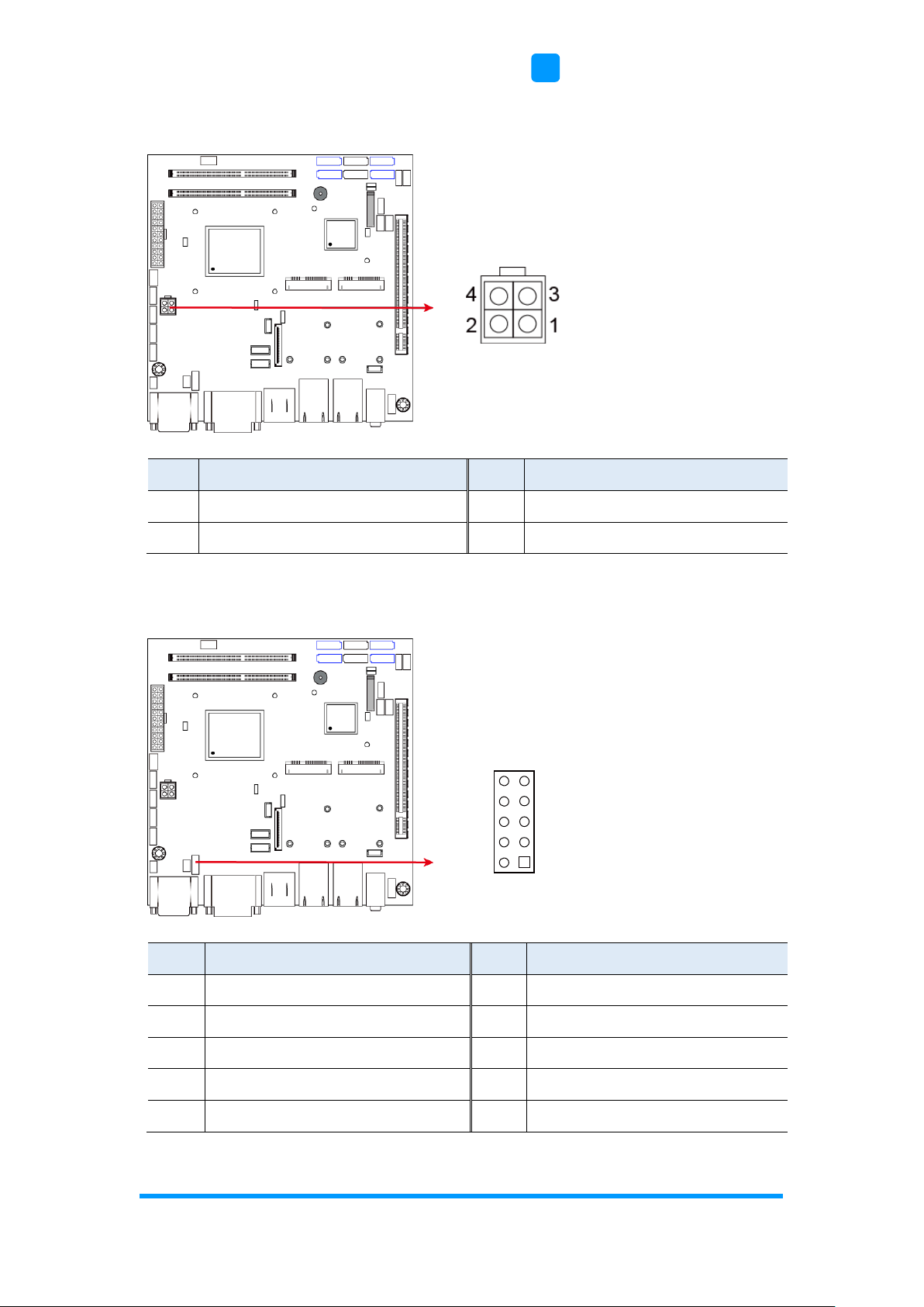
2.5.14 ATX 12V Power Connector (J6)
Pin
Assigment
Pin
Assigment
1
Ground
2
Ground
3
+12V
4
+12V
2.5.15 Digital I/O Connector (J8)
Pin
Assigment
Pin
Assigment
1
Ground
2
+5V
3
Out3
4
Out1
5
Out2
6
Out0
7
IN3
8
IN1
9
IN2
10
IN0
9
1
10
2

34
ASTUT-152-RE1S User Manual
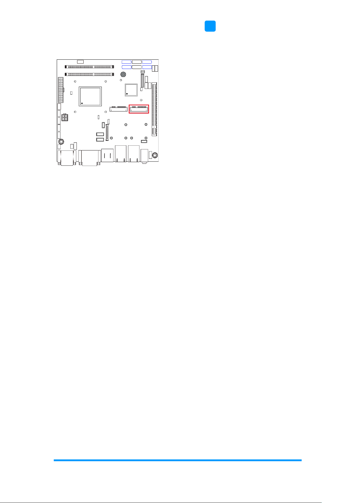
2.5.16 DDR3 SO-DIMM Socket (J10, J11)
2.5.17 Audio Connector for Front Panel (J21)
Pin
Assigment
Pin
Assigment
1
MIC IN_L
2
Ground
3
MIC IN_R
4
DET
5
LINE_R
6
Ground
7
Sense
8
KEY
9
LINE_L
10
Ground
9
1
10
2

Motherboard Information
ASTUT-152-RE1S User Manual
35
2
2.5.18 Front Panel Settings (J22)
Pin
Assigment
Pin
Assigment
1
Power BTN
2
Power BTN
3
HDD LED+
4
HDD LED-
5
Reset BTN
6
Reset BTN
7
Power LED+
8
Power LED-
2.5.19 CPU Fan Power Connector (CPU_FAN1)
Pin
Assigment
Pin
Assigment
1
Ground
3
Rotation detection
2
+12V
4
Control
1
2
8
7
1

36
ASTUT-152-RE1S User Manual
2.5.20 System Fan Power Connector (SYS_FAN1)
Pin
Assigment
Pin
Assigment
1
Ground
3
Rotation detection
2
+12V
4
Control
2.5.21 Mini PCIe / mSATA Connector (J14)
1
Motherboard Information
ASTUT-152-RE1S User Manual
37
2
2.5.22 Mini PCIe Connector (J15)

38
Chapter 3
Driver Installation
The information provided in this chapter includes:
• Intel
®
Chipset Software Installation Utility
• VGA Driver Installation
• HD Audio Driver Installation
• LAN Driver Installation
• Intel
®
Management Engine (ME) Interface
• Intel
®
USB 3.0 Driver Installation

Driver Installation
ASTUT-152-RE1S User Manual
39
3
3.1 Introduction
This section describes the installation procedures for software drivers. The
software drivers are in a disk enclosed with the product package. If you find
anything missing, please contact the distributor where you made the
purchase.
Note: After installing your Windows operating system, you must install the
Intel® Chipset Software Installation Utility first before proceeding with
the drivers installation.
3.2 Intel® Chipset Software Installation Utility
The Intel® Chipset drivers should be installed first before the software drivers
to install INF files for Plug & Play function for the chipset components. Follow
the instructions below to complete the installation.
1. Insert the disk enclosed in the package. Click Intel and then Intel(R) 8
Series Chipset Drivers.
2. Click Intel(R) Chipset Software Installation Utility.
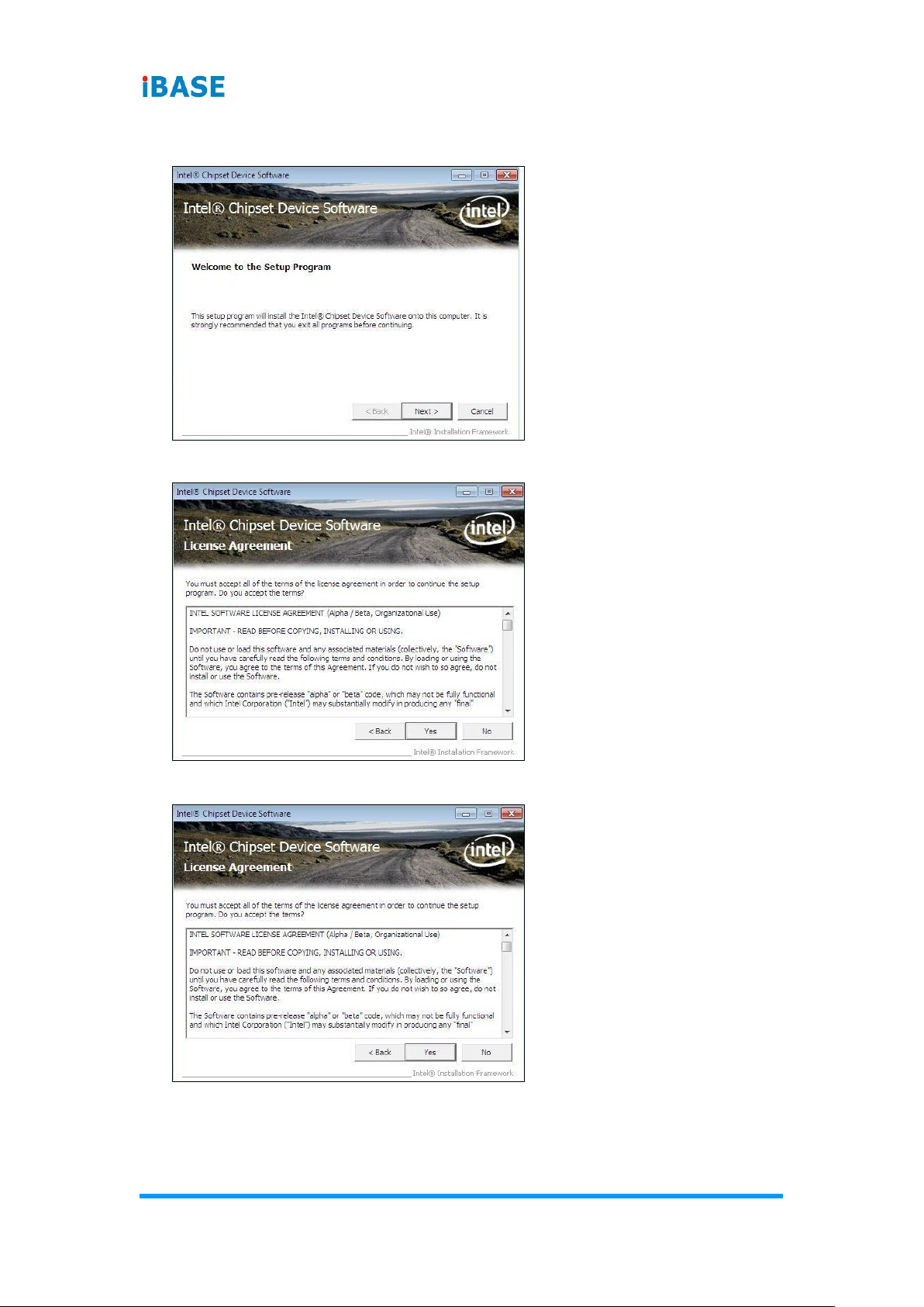
40
ASTUT-152-RE1S User Manual
3. When the Welcome screen to the Intel
®
Chipset Device Software appears,
click Next to continue.
4. Click Yes to accept the software license agreement.
5. On the Readme File Information screen, click Next for installation.
6. After the driver is completely installed, click Finish and restart the
computer for changes to take effect.

Driver Installation
ASTUT-152-RE1S User Manual
41
3
3.3 VGA Driver Installation
1. Click Intel and then Intel(R) 8 Series Chipset Drivers.
2. Click Intel(R) Core(TM) i3/i5/i7 Graphics Driver.
3. When the Welcome screen appears, click Next to continue.
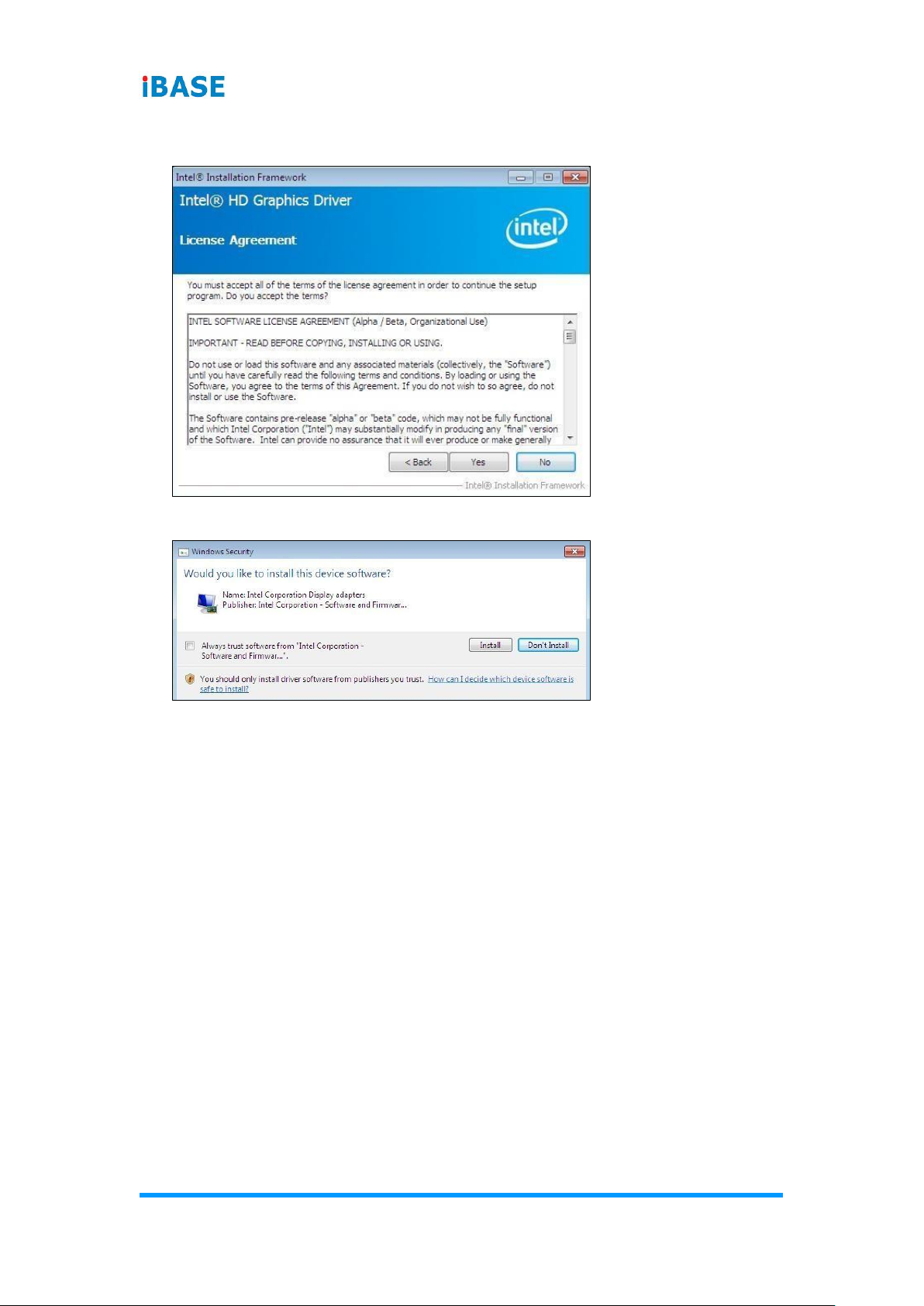
42
ASTUT-152-RE1S User Manual
4. Click Yes to agree with the license agreement and continue the
installation.
5. Click Install.
6. After the driver is completely installed, click Finish and restart the
computer for changes to take effect.

Driver Installation
ASTUT-152-RE1S User Manual
43
3
3.4 HD Audio Driver Installation
1. Click Intel and then Intel(R) 8 Series Chipset Drivers.
2. Click Realtek High Definition Audio Driver.
3. On the Welcome screen of the InstallShield Wizard, click Yes for
installation.
4. After the driver is completely installed, click Finish and restart the
computer for changes to take effect.

44
ASTUT-152-RE1S User Manual
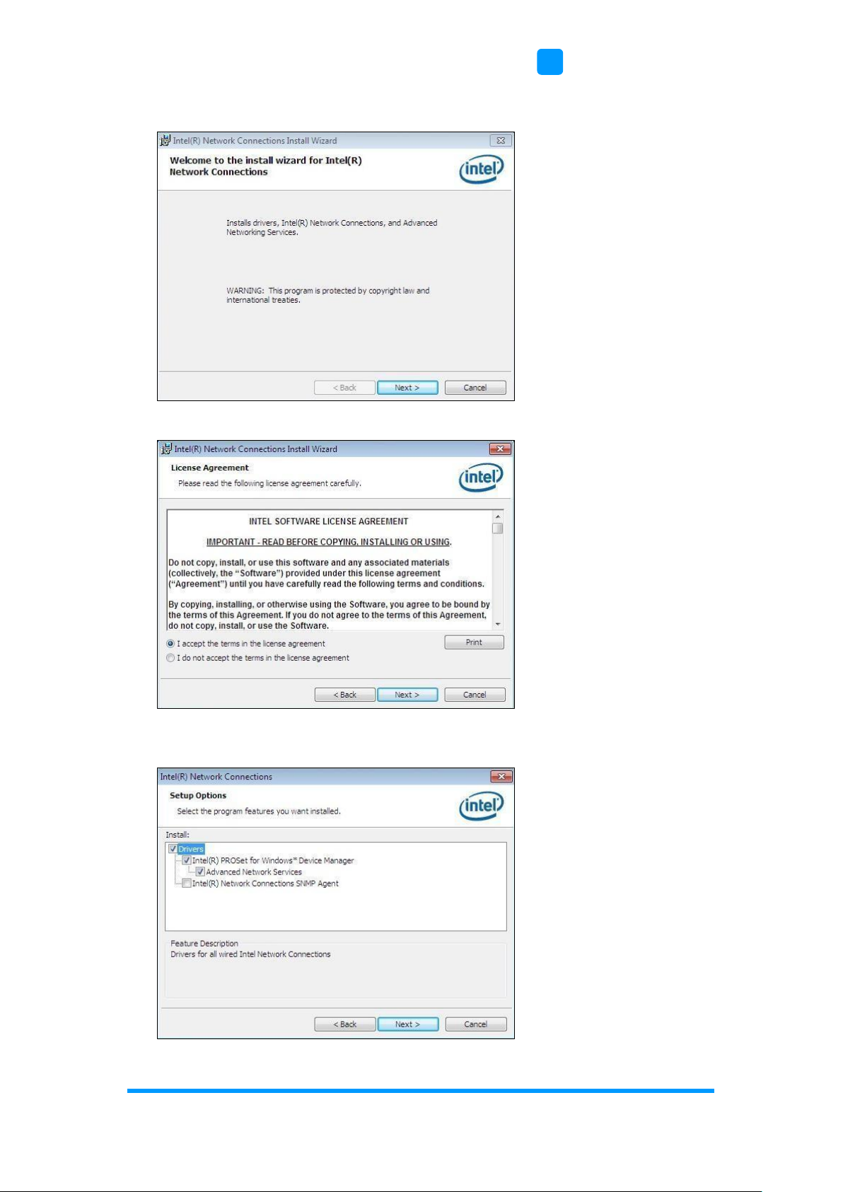
3.5 LAN Driver Installation
1. Click Intel and then Intel(R) 8 Series Chipset Drivers.
2. Click Intel(R) PRO LAN Network Drivers.
3. Click Install Drivers and Software.
Driver Installation
ASTUT-152-RE1S User Manual
45
3
4. When the Welcome screen appears, click Next to continue.
5. Agree with the license agreement and click Next.
6. Tick the checkbox for Drivers on the Setup Options screen and click Next
to continue.

46
ASTUT-152-RE1S User Manual
7. Click Install.
8. After the driver is completely installed, click Finish and restart the
computer for changes to take effect.

Driver Installation
ASTUT-152-RE1S User Manual
47
3
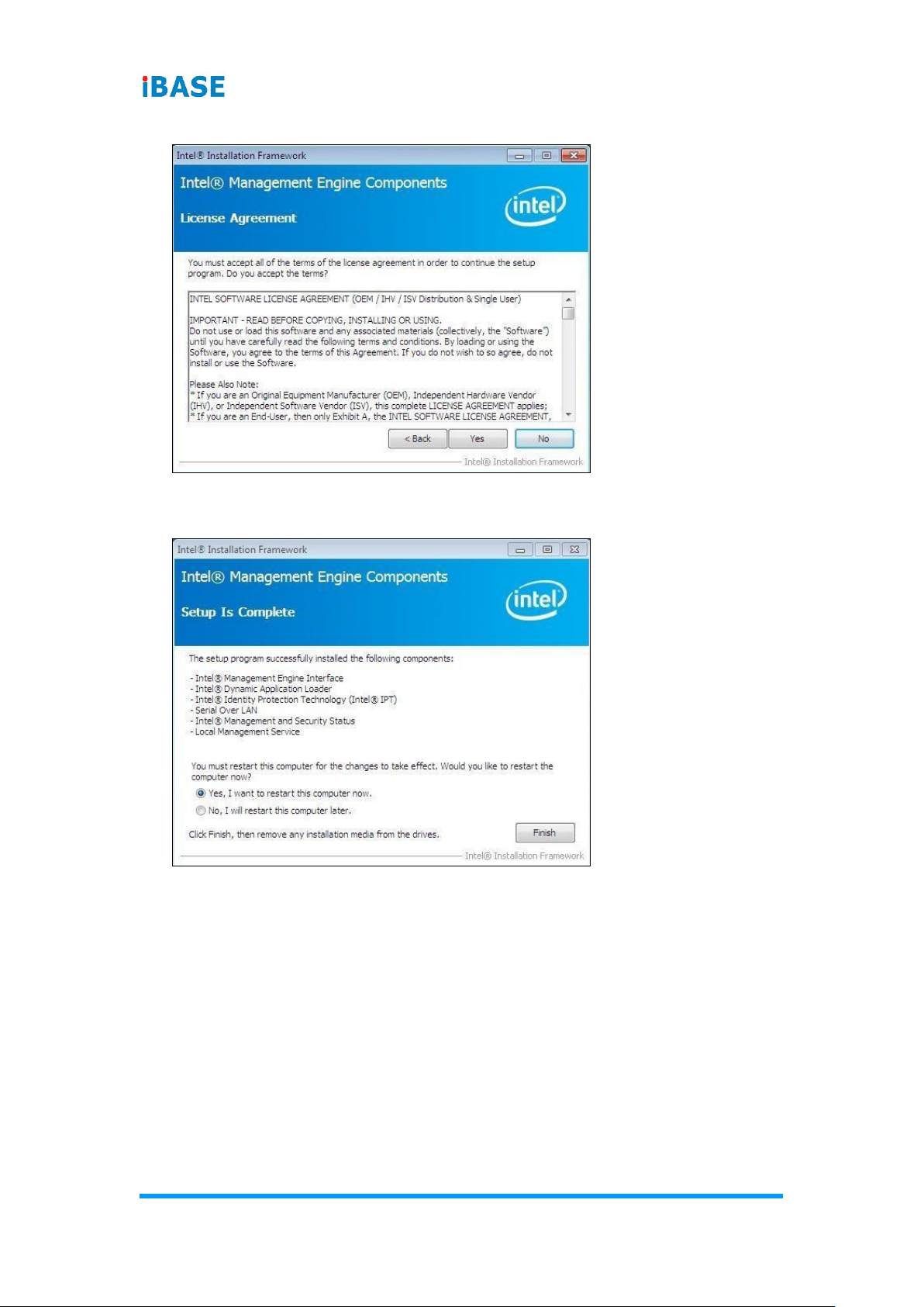
3.6 Intel® Management Engine (ME) Interface
Note: You are suggested to install the latest version of Microsoft .NET
framework to run this application correctly. This driver requires
Microsoft .NET Framework 3.5 or later.
1. Click Intel, and then Intel(R) 8 Series Chipset Drivers.
2. Click Intel(R) ME 9.0 Drivers.
3. When the Welcome screen appears, tick the checkbox for Install Intel®
Control Center and click Next..
48
ASTUT-152-RE1S User Manual
4. Click Yes to agree with the license agreement.
5. When the Setup Progress screen appears, click Next to continue the
installation.
6. After the driver is completely installed, click Finish and restart the
computer for changes to take effect.
Driver Installation
ASTUT-152-RE1S User Manual
49
3
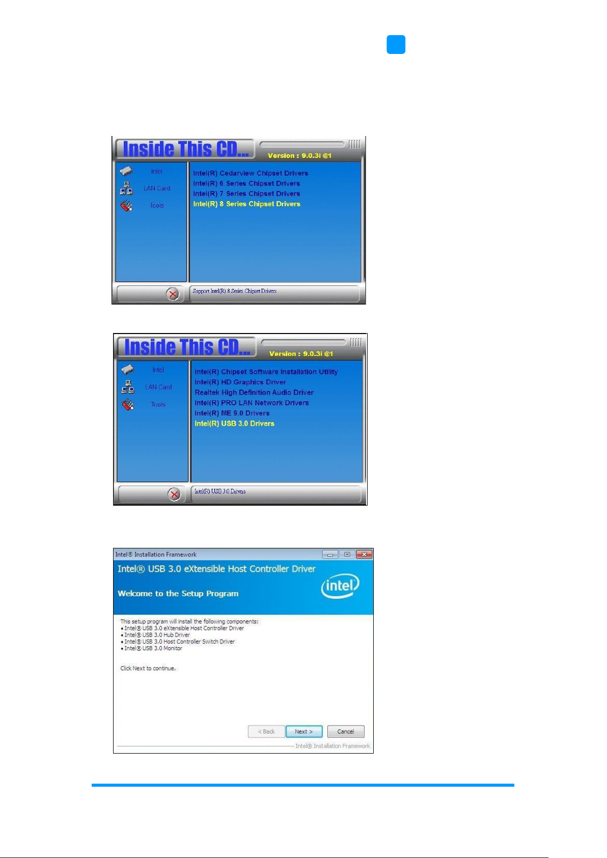
3.7 Intel® USB 3.0 Drivers
1. Insert the disk enclosed in the package. Click Intel and then Intel(R) 8
Series Chipset Drivers.
2. Click Intel(R) USB 3.0 Drivers.
3. When the Welcome screen to the Intel
®
USB 3.0 eXtensible Host
Controller Driver appears, click Next to continue.

50
ASTUT-152-RE1S User Manual
4. Click Yes to accept the software license agreement.
5. On the Readme File Information screen, click Next for installation.
6. After the driver is completely installed, click Finish and restart the
computer for changes to take effect.

51
Chapter 4
BIOS Setup
This chapter describes the different settings available in the AMI
BIOS that comes with the board. The topics covered in this
chapter are as follows:
• Main Settings
• Advanced Settings
• Chipset Settings
• Boot Settings
• Security Settings
• Save & Exit

52
ASTUT-152-RE1S User Manual
4.1 Introduction
The BIOS (Basic Input/Output System) installed in the ROM of your computer
system supports Intel® processors. The BIOS provides critical low-level
support for standard devices such as disk drives, serial ports and parallel
ports. It also provides password protection as well as special support for
detailed fine-tuning of the chipset controlling the entire system.
4.2 BIOS Setup
The BIOS provides a Setup utility program for specifying the system
configurations and settings. The BIOS ROM of the system stores the Setup
utility. When you turn on the computer, the BIOS is immediately activated.
Press the <Del> key immediately allows you to enter the Setup utility. If you
are a little bit late pressing the <Del> key, POST (Power On Self Test) will
continue with its test routines, thus preventing you from invoking the Setup.
If you still need to enter Setup, restart the system by pressing the ”Reset”
button or simultaneously pressing the <Ctrl>, <Alt> and <Delete> keys.
You can also restart by turning the system Off and back On again.
The following message will appear on the screen:
Press <DEL> to Enter Setup
In general, press the arrow keys to highlight items, <Enter> to select, the
<PgUp> and <PgDn> keys to change entries, <F1> for help, and <Esc> to
quit.
When you enter the BIOS Setup utility, the Main Menu screen will appear on
the screen. The Main Menu allows you to select from various setup functions
and exit choices.
Warning: It is strongly recommended that you avoid making any changes to
the chipset defaults.
These defaults have been carefully chosen by both AMI and your
system manufacturer to provide the absolute maximum
performance and reliability. Changing the defaults could make the
system unstable and crash in some cases.
BIOS Setup
ASTUT-152-RE1S User Manual
53
4
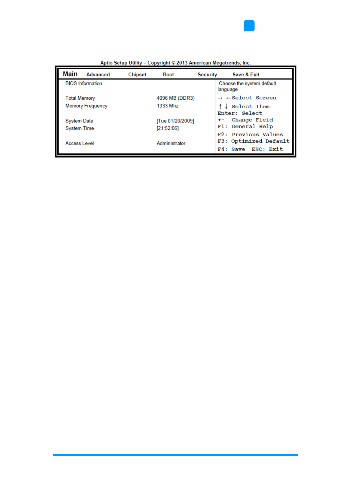
4.3 Main Settings
System Date
Set the Date. Use Tab to switch between Data elements.
System Time
Set the Time. Use Tab to switch between Data elements.
54
ASTUT-152-RE1S User Manual
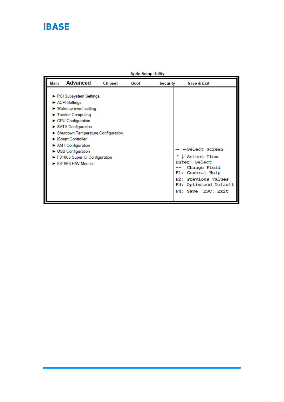
4.4 Advanced Settings
This section allows you to configure, improve your system and allows you to
set up some system features according to your preference.

BIOS Setup
ASTUT-152-RE1S User Manual
55
4
4.4.1 PCI Subsystem Settings
PCI Latency Timer
Value to be programmed into PCI Latency Timer Register.
VGA Palette Snoop
Enables or disables VGA Palette Registers Snooping.
PERR# Generation
Enables or disables PCI device to generate PERR#.
SERR# Generation
Enables or disables PCI device to generate SERR#.
PCI Express Settings
Change PCI Express devices settings. Value to be programmed into PCI
Latency Timer Register.

56
ASTUT-152-RE1S User Manual
4.4.1.1. PCI Express Settings
Relaxed Ordering
Enables or disables PCI Express Device Relaxed Ordering.
Extended Tag
If ENABLED allows device to use 8-bit Tag field as a requester.
No Snoop
Enables or disables PCI Express Device No Snoop option.
Maximum Payload
Set Maximum Payload of PCI Express Device or allow System BIOS to select
the value.
Maximum Read Request
Set Maximum Read Request Size of PCI Express Device or allow System
BIOS to select the value.
ASPM Support
Set the ASPM Level: Force L0s – Force all links to L0s State: AUTO – BIOS
auto configure: DISABLE – Disables ASPM.
Extended Synch
If ENABLED allows generation of Extended Synchronization patterns.

BIOS Setup
ASTUT-152-RE1S User Manual
57
4
Link Training Retry
Defines number of Retry Attempts software will take to retrain the link if
previous training attempt was unsuccessful.
Link Training Timeout (uS)
Defines number of Microseconds software will wait before polling ‘Link
Training’ bit in Link Status register. Value range from 10 to 1000 uS.
Unpopulated Links
In order to save power, software will disable unpopulated PCI Express links, if
this option set to ‘Disable Link’.
Restore PCIE Registers
On non-PCI Express aware OS’s (Pre Windows Vista) some devices may not
be correctly reinitialized after S3. Enabling this restore PCI Express device
configuration on S3 resume
Warning: Enabling this may cause issues with other hardware after S3
resume.

58
ASTUT-152-RE1S User Manual
4.4.2 ACPI Settings
Enable Hibernation
Enables or Disables System ability to Hibernate (OS/S4 Sleep State). This
option may be not effective with some OS.
ACPI Sleep State
Select ACPI sleep state the system will enter, when the SUSPEND button is
pressed.
Lock Legacy Resources
Enabled or Disabled Lock of Legacy Resources.
S3 Video Repost
Enable or disable S3 Video Repost.

BIOS Setup
ASTUT-152-RE1S User Manual
59
4
4.4.3 Wake up Event Settings
Wake on PCIE PME Wake Event
The options are Disabled and Enabled.
4.4.4 Trusted Computing
TPM Support
This configuration is supported only with MI980VF. Enables or Disables TPM
support. O.S. will not show TPM. Reset of platform is required.
Security Device Support
Enables or disables BIOS support for security device. O.S. will not show
Security Device. TCG EFI protocol and INT1A interface will not be available.
60
ASTUT-152-RE1S User Manual
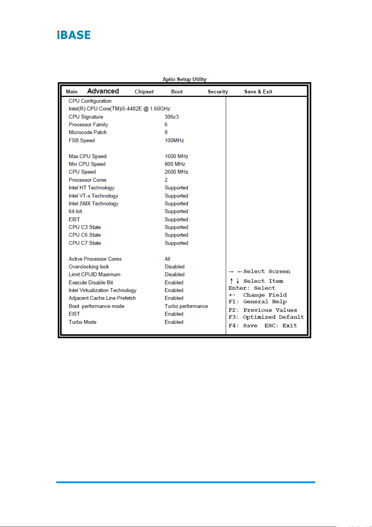
4.4.5 CPU Configuration
This section shows the CPU configuration parameters.
Active Processor Cores
Number of cores to enable in each processor package.
Overclocking lock
Flex_RATIO(194)MSR
Limit CPUID Maximum
Disabled for Windows XP.
Execute Disable Bit
XD can prevent certain classes of malicious buffer overflow attacks when
combined with a supporting OS

BIOS Setup
ASTUT-152-RE1S User Manual
61
4
Intel Virtualization Technology
When enabled, a VMM can utilize the additional hardware capabilities
provided by Vanderpool Technology.
Adjacent Cache Line Prefetch
To turn on/off prefetching of adjacent cache lines.
Boot Performance Mode
Select the performance state that the BIOS will set before OS handoff.
EIST
Enabled/Disabled Intel Speedstep.
4.4.6 SATA Configuration
SATA Controller(s)
Enable / Disable Serial ATA Controller.
SATA Mode Selection
(1) IDE Mode
(2) AHCI Mode
(3) RAID Mode. (This configuration is supported only with MI980VF)

62
ASTUT-152-RE1S User Manual
4.4.7 Shutdown Temperature Configuration
ACPI Shutdown Temperature
The default setting is Disabled.
4.4.8 iSmart Controller
iSmart Controller
Setup the power on time for the system.
Schedule Slot 1 / 2
Setup the hour/minute for system power on.

BIOS Setup
ASTUT-152-RE1S User Manual
63
4
4.4.9 AMT Controller
AMT Configuration
This configuration is supported only with MI980VF (with iAMT function).
Options are Enabled and Disabled.
Note: iAMT H/W is always enabled. This option just controls the BIOS
extension execution. If enabled, this requires additional firmware in the SPI
device.
Unconfigure ME
Perform AMT/ME unconfigure without password operation.
Amt Wait Timer
Set timer to wait before sending ASF_GET_BOOT_OPTIONS.
Activate Remote Assistance Process
Trigger CIRA boot.
PET Progress
User can Enable/Disable PET Events progress to receive PET events or not.
Watchdog Timer
Enable/Disable Watchdog Timer.
64
ASTUT-152-RE1S User Manual
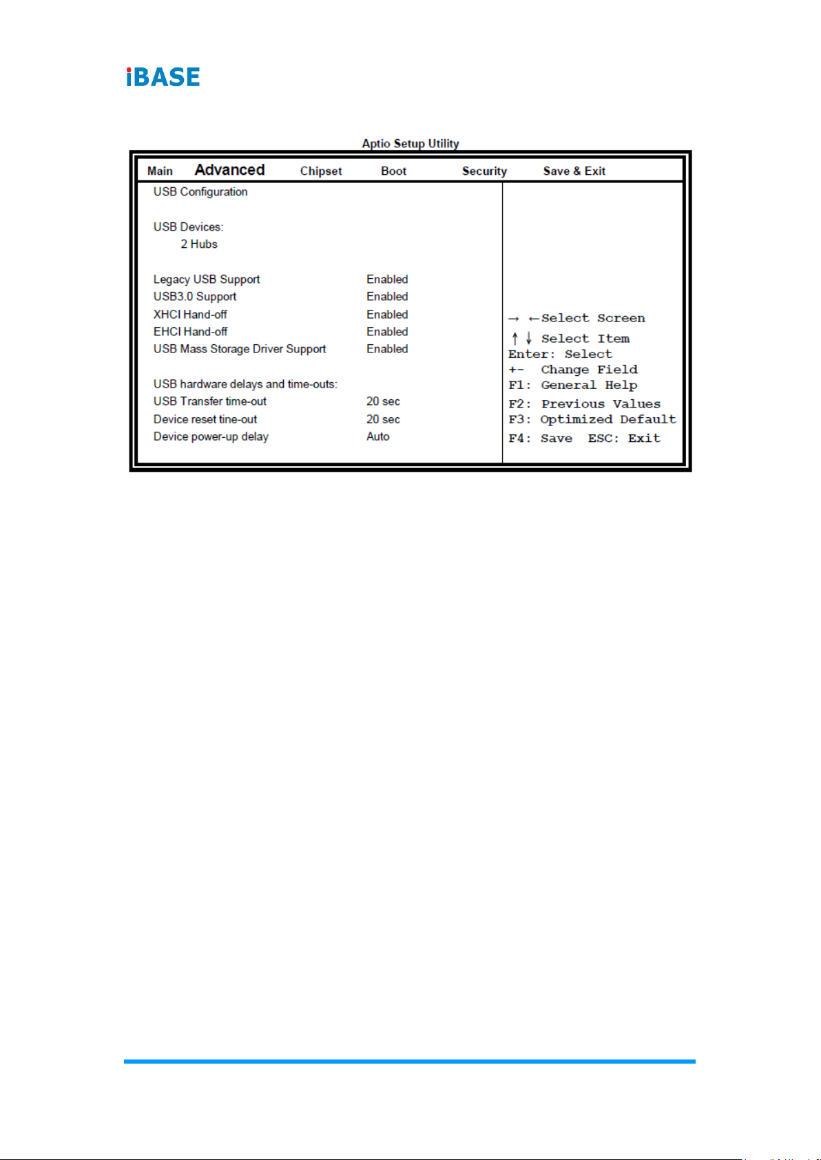
4.4.10 USB Configuration
Legacy USB Support
Enables Legacy USB support. AUTO option disables legacy support if no USB
devices are connected. DISABLE option will keep USB devices available only
for EFI applications.
USB3.0 Support
Enable/Disable USB3.0 (XHCI) Controller support.
XHCI Hand-off
This is a workaround for OSes without XHCI hand-off support. The XHCI
ownership change should be claimed by XHCI driver.
EHCI Hand-off
Enabled/Disabled. This is a workaround for OSes without EHCI hand-off
support. The EHCI ownership change should be claimed by EHCI driver.
USB Mass Storage Driver Support
Enable/Disable USB Mass Storage Driver Support.
USB Transfer time-out
The time-out value for Control, Bulk, and Interrupt transfers.
Device reset time-out
USB mass Storage device start Unit command time-out.
Device power-up delay
Maximum time the device will take before it properly reports itself to the Host
Controller. ‘Auto’ uses default value: for a Root port it is 100ms, for a Hub port
the delay is taken from Hub descriptor.
BIOS Setup
ASTUT-152-RE1S User Manual
65
4
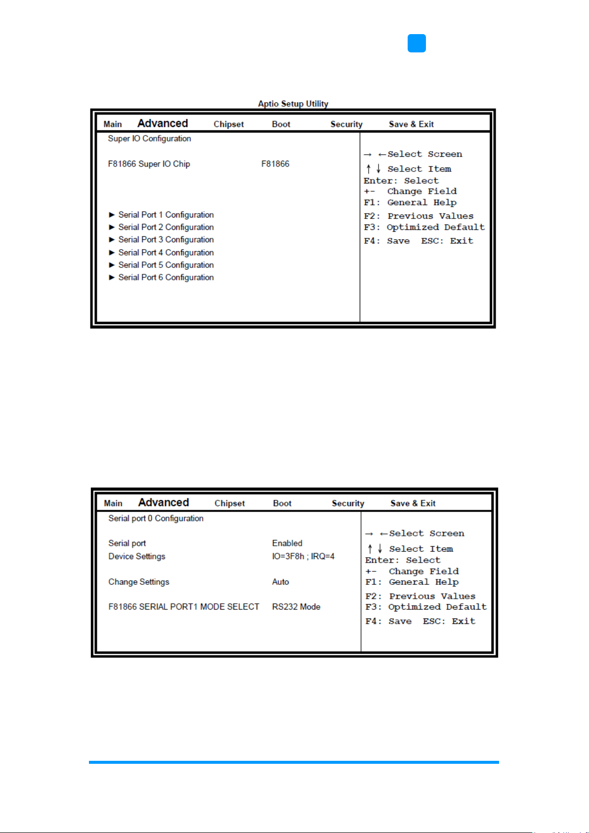
4.4.11 F8186 Super IO Configuration
Serial Port Configuration
Set Parameters of Serial Ports. User can Enable/Disable the serial port and
Select an optimal settings for the Super IO Device.
4.4.11.1. Serial Port Configuration
F81866 SERIAL PORT1 MODE SELECT
F81866 SERIAL PORT1 LOOP Back/RS232/RS422/RS485 mode select.

66
ASTUT-152-RE1S User Manual
4.4.12 F81866 Hardware Monitor
Temperatures/Voltages
These fields are the parameters of the hardware monitoring function feature of
the motherboard. The values are read-only values as monitored by the system
and show the PC health status.
Fan1/Fan2 Smart Fan Control
This field enables or disables the smart fan feature. At a certain temperature,
the fan starts turning. Once the temperature drops to a certain level, it stops
turning again.

BIOS Setup
ASTUT-152-RE1S User Manual
67
4
4.5 Chipset Settings
4.5.1 PCH-IO Configuration
PCH LAN Controller
Enable or disable onboard NIC.
Wake on LAN
Enable or disable integrated LAN to wake the system. (The Wake On LAN
cannot be disabled if ME is on at Sx state.)
SLP_LAN# Low on DC Power
Enable or Disable SLP_LAN# Low on DC Power.
68
ASTUT-152-RE1S User Manual
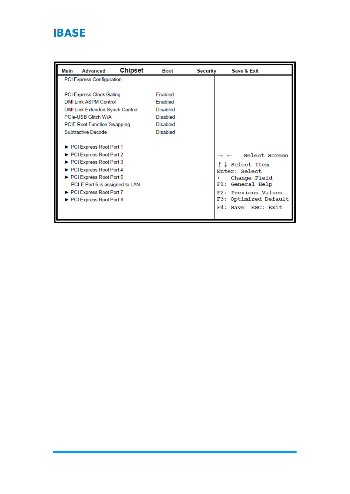
4.5.1.1. PCI Express Configuration
PCI Express Clock Gating
Enable or disable PCI Express Clock Gating for each root port.
DMI Link ASPM Control
The control of Active State Power Management on both NB side and SB side
of the DMI link.
PCIe-USB Glitch W/A
PCIe-USB Glitch W/A for bad USB device(s) connected behind PCIE/PEG
port.
BIOS Setup
ASTUT-152-RE1S User Manual
69
4
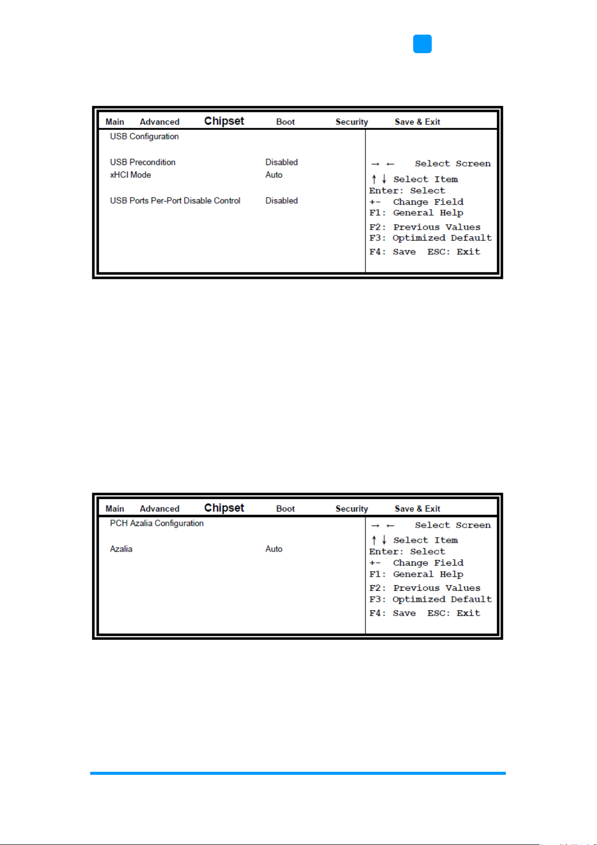
4.5.1.2. USB Configuration
USB Precondition
Precondition work on USB host controller and root ports for faster
enumeration.
xHCI Mode
Mode of operation of xHCI controller.
USB Ports Per-Port Disable Control
Control each of the USB ports (0~13) disabling.
4.5.1.3. PCH Azalia Configuration
Azalia
Control Detection of the Azalia device. Disabled = Azalia will be
unconditionally be disabled. Enabled = Azalia will be unconditionally be
enabled. Auto = Azalia will be enabled if present, disabled otherwise.
70
ASTUT-152-RE1S User Manual
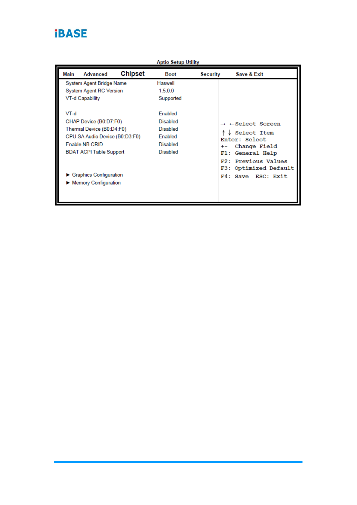
4.5.2 System Agent (SA) Configuration
VT-d
Check to enable VT-d function on MCH.
Enable NB CRID
Enable or disable NB CRID WorkAround.

BIOS Setup
ASTUT-152-RE1S User Manual
71
4
Graphics Configuration
Primary Display
Select which of IGFX/PEG/PCI graphics device should be primary display or
select SG for switchable Gfx.
Primary PEG
Select PEGO/PEG1/PEG2/PEG3 Graphics device should be Primary PEG.
Primary PCIE
Select PCIE0/PCIE1/PCIE2/PCIE3/PCIE4/PCIE5/PCIE6PCIE7 Graphics
device should be primary PCIE.
Internal Graphics
Keep IGD enabled based on the setup options.
DVMT Pre-Allocated
Select DVMT 5.0 Pre-Allocated (Fixed) graphics memory size used by the
internal graphics device.
DVMT Total Gfx Mem
Select DVMT 5.0 total graphics memory size used by the internal graphics
device.

72
ASTUT-152-RE1S User Manual
Primary IGFX Boot Display
Select the Video Device that will be activated during POST. This has no effect
if external graphics present. Secondary booty display selection will appear
based on your selection. VGA modes will be supported only on primary
display.
LVDS/EDP Control
LVDS/EDP Control
Gfx Low Power Mode
This option is applicable for SFF only.
Memory Configuration

BIOS Setup
ASTUT-152-RE1S User Manual
73
4
4.6 Boot Settings
Setup Prompt Timeout
Number of seconds to wait for setup activation key. 65535(0xFFFF) means
indefinite waiting.
Bootup NumLock State
Select the keyboard NumLock state.
Quiet Boot
Enables/Disables Quiet Boot option.
Fast Boot
Enables/Disables boot with initialization of a minimal set of devices required to
launch active boot option. Has no effect for BBS boot options.
Boot Option Priorities
Sets the system boot order.

74
ASTUT-152-RE1S User Manual
4.6.1 CSM Parameters
Boot Option Filter
This option controls what devices system can boot to.
Launch PXE OpROM Policy
Controls the execution of UEFI and Legacy PXE OpROM.
Launch Storatge OpROM Policy
Controls the execution of UEFI and Legacy Storage OpROM.
Launch Video OpROM Policy
Controls the execution of UEFI and Legacy Video OpROM.
Other PCI Device ROM Priority
For PCI devices other than Network, Mass storage or Video defines which
OpROM to launch.
BIOS Setup
ASTUT-152-RE1S User Manual
75
4
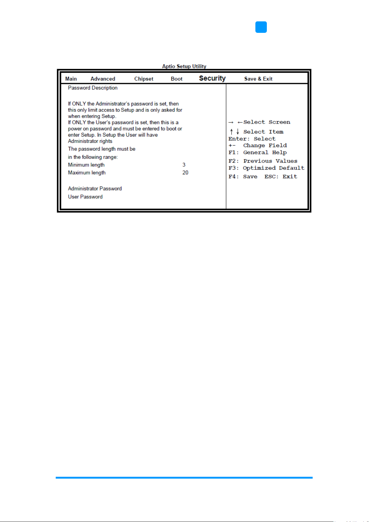
4.7 Security Settings
Administrator Password
Set Setup Administrator Password.
User Password
Set User Password.

76
ASTUT-152-RE1S User Manual
4.8 Save & Exit Settings
Save Changes and Exit
Exit system setup after saving the changes.
Discard Changes and Exit
Exit system setup without saving any changes.
Save Changes and Reset
Reset the system after saving the changes.
Discard Changes and Reset
Reset system setup without saving any changes.
Save Changes
Save Changes done so far to any of the setup options.
Discard Changes
Discard Changes done so far to any of the setup options.
Restore Defaults
Restore/Load Defaults values for all the setup options.
Save as User Defaults
Save the changes done so far as User Defaults.
Restore User Defaults
Restore the User Defaults to all the setup options.

77
Appendix
This section provides the mapping addresses of peripheral
devices and the sample code of watchdog timer configuration.
• I/O Port Address Map
• Interrupt Request Lines (IRQ)
• Digital I/O Sample Code
• Watchdog Timer Configuration

78
ASTUT-152-RE1S User Manual
A. I/O Port Address Map
Each peripheral device in the system is assigned a set of I/O port addresses
which also becomes the identity of the device. The following table lists the I/O
port addresses used.
Address
Device Description
000h - 01Fh
DMA Controller #1
020h - 03Fh
Interrupt Controller #1
040h - 05Fh
Timer
060h - 06Fh
Keyboard Controller
070h - 07Fh
Real Time Clock, NMI
080h - 09Fh
DMA Page Register
0A0h - 0BFh
Interrupt Controller #2
0C0h - 0DFh
DMA Controller #2
0F0h
Clear Math Coprocessor Busy Signal
0F1h
Reset Math Coprocessor
1F0h - 1F7h
IDE Interface
2F8h - 2FFh
Serial Port #2(COM2)
2B0h- 2DFh
Graphics adapter Controller
360h - 36Fh
Network Ports
3F8h - 3FFh
Serial Port #1(COM1)

Appendix
ASTUT-152-RE1S User Manual
79
B. Interrupt Request Lines (IRQ)
Peripheral devices use interrupt request lines to notify CPU for the service
required. The following table shows the IRQ used by the devices on board.
Level
Function
IRQ0
System Timer Output
IRQ1
Keyboard
IRQ3
Serial Port #2
IRQ4
Serial Port #1
IRQ8
Real Time Clock
IRQ14
Primary IDE
IRQ15
Secondary IDE

80
ASTUT-152-RE1S User Manual
C. Watchdog Timer Configuration
The Watchdog Timer (WDT) is used to generate a variety of output signals
after a user programmable count. The WDT is suitable for the use in the
prevention of system lock-up, such as when software becomes trapped in a
deadlock. Under these sorts of circumstances, the timer will count to zero and
the selected outputs will be driven.
Under normal circumstance, you will need to restart the WDT at regular
intervals before the timer counts to zero.
Sample Code:
//--------------------------------------------------------------------------//
// THIS CODE AND INFORMATION IS PROVIDED "AS IS" WITHOUT WARRANTY OF ANY
// KIND, EITHER EXPRESSED OR IMPLIED, INCLUDING BUT NOT LIMITED TO THE
// IMPLIED WARRANTIES OF MERCHANTABILITY AND/OR FITNESS FOR A
PARTICULAR
// PURPOSE.
//
//--------------------------------------------------------------------------#include <dos.h>
#include <conio.h>
#include <stdio.h>
#include <stdlib.h>
#include "F81866.H"
//--------------------------------------------------------------------------int main (int argc, char *argv[]); void EnableWDT(int);
void DisableWDT(void);
//--------------------------------------------------------------------------int main (int argc, char *argv[])
{
unsigned char bBuf; unsigned char bTime; char **endptr;
char SIO;
printf("Fintek 81866 watch dog program\n"); SIO = Init_F81866();
if (SIO == 0)
{
printf("Can not detect Fintek 81866, program abort.\n"); return(1);
}//if (SIO == 0)
if (argc != 2)
{
printf(" Parameter incorrect!!\n"); return (1);
}
bTime = strtol (argv[1], endptr, 10);
printf("System will reset after %d seconds\n", bTime);
if (bTime)
{ EnableWDT(bTime); } else

Appendix
ASTUT-152-RE1S User Manual
81
{ DisableWDT(); }
return 0;
}
//--------------------------------------------------------------------------void EnableWDT(int interval)
{
unsigned char bBuf;
bBuf = Get_F81866_Reg(0x2B); bBuf &= (~0x20);
Set_F81866_Reg(0x2B, bBuf); //Enable WDTO
Set_F81866_LD(0x07); //switch to logic device 7
Set_F81866_Reg(0x30, 0x01); //enable timer
bBuf = Get_F81866_Reg(0xF5); bBuf &= (~0x0F);
bBuf |= 0x52;
Set_F81866_Reg(0xF5, bBuf); //count mode is second Set_F81866_Reg(0xF6,
interval); //set timer
bBuf = Get_F81866_Reg(0xFA); bBuf |= 0x01;
Set_F81866_Reg(0xFA, bBuf); //enable WDTO output
bBuf = Get_F81866_Reg(0xF5); bBuf |= 0x20;
Set_F81866_Reg(0xF5, bBuf); //start counting
}
//--------------------------------------------------------------------------void DisableWDT(void)
{
unsigned char bBuf;
Set_F81866_LD(0x07); //switch to logic device 7 bBuf = Get_F81866_Reg(0xFA);
bBuf &= ~0x01;
Set_F81866_Reg(0xFA, bBuf); //disable WDTO output
bBuf = Get_F81866_Reg(0xF5); bBuf &= ~0x20;
bBuf |= 0x40;
Set_F81866_Reg(0xF5, bBuf); //disable WDT
}
//

82
ASTUT-152-RE1S User Manual
//--------------------------------------------------------------------------//
// THIS CODE AND INFORMATION IS PROVIDED "AS IS" WITHOUT WARRANTY OF ANY
// KIND, EITHER EXPRESSED OR IMPLIED, INCLUDING BUT NOT LIMITED TO THE
// IMPLIED WARRANTIES OF MERCHANTABILITY AND/OR FITNESS FOR A
PARTICULAR
// PURPOSE.
//
//--------------------------------------------------------------------------#include "F81866.H"
#include <dos.h>
//--------------------------------------------------------------------------unsigned int F81866_BASE; void Unlock_F81866 (void); void Lock_F81866 (void);
//--------------------------------------------------------------------------unsigned int Init_F81866(void)
{
unsigned int result; unsigned char ucDid;
F81866_BASE = 0x4E;
result = F81866_BASE;
ucDid = Get_F81866_Reg(0x20);
if (ucDid == 0x07) //Fintek 81866
{ goto Init_Finish; }
F81866_BASE = 0x2E;
result = F81866_BASE;
ucDid = Get_F81866_Reg(0x20);
if (ucDid == 0x07) //Fintek 81866
{ goto Init_Finish; }
F81866_BASE = 0x00;
result = F81866_BASE;
Init_Finish:
return (result);
}
//--------------------------------------------------------------------------void Unlock_F81866 (void)
{
outportb(F81866_INDEX_PORT, F81866_UNLOCK); outportb(F81866_INDEX_PORT,
F81866_UNLOCK);
}
//--------------------------------------------------------------------------void Lock_F81866 (void)
{
outportb(F81866_INDEX_PORT, F81866_LOCK);
}
//--------------------------------------------------------------------------void Set_F81866_LD( unsigned char LD)
{
Unlock_F81866();
outportb(F81866_INDEX_PORT, F81866_REG_LD);
outportb(F81866_DATA_PORT, LD); Lock_F81866();
}

Appendix
ASTUT-152-RE1S User Manual
83
//--------------------------------------------------------------------------void Set_F81866_Reg( unsigned char REG, unsigned char DATA)
{
Unlock_F81866(); outportb(F81866_INDEX_PORT, REG); outportb(F81866_DATA_PORT,
DATA); Lock_F81866();
}
//---------------------------------------------------------------------------
unsigned char Get_F81866_Reg(unsigned char REG)
{
unsigned char Result; Unlock_F81866();
outportb(F81866_INDEX_PORT, REG); Result = inportb(F81866_DATA_PORT);
Lock_F81866();
return Result;
}
//---------------------------------------------------------------------------
//--------------------------------------------------------------------------//
// THIS CODE AND INFORMATION IS PROVIDED "AS IS" WITHOUT WARRANTY OF ANY
// KIND, EITHER EXPRESSED OR IMPLIED, INCLUDING BUT NOT LIMITED TO THE
// IMPLIED WARRANTIES OF MERCHANTABILITY AND/OR FITNESS FOR A
PARTICULAR
// PURPOSE.
//
//--------------------------------------------------------------------------#ifndef F81866_H
#define F81866_H 1
//--------------------------------------------------------------------------#define F81866_INDEX_PORT (F81866_BASE)
#define F81866_DATA_PORT (F81866_BASE+1)
//--------------------------------------------------------------------------#define F81866_REG_LD 0x07
//--------------------------------------------------------------------------#define F81866_UNLOCK 0x87
#define F81866_LOCK 0xAA
//--------------------------------------------------------------------------unsigned int Init_F81866(void);
void Set_F81866_LD( unsigned char);
void Set_F81866_Reg( unsigned char, unsigned char); unsigned char
Get_F81866_Reg( unsigned char);
//--------------------------------------------------------------------------#endif // F81866_H
 Loading...