

Page 1
www.ibase.com.tw
IBASE Technology Inc.
SMARC Evaluation Kit
User’s Manual
2014 Oct V1.1
Page 2

Copyright © 2013 IBASE Technology Inc. All Rights Reserved. 2
2
SMARC Evaluation Kit
Page 3

3
3
IBASE Technology Inc.
Quick Start Guide
Here is a step by step guide to boot up your SMARC:
a. By default, the (Android) or (Linux OS) has been preloaded in the eMMC, (or SD card)
of the SMARC demo kit. All you have to do is
- Connect your SMARC with TV/LCD by using an HDMI cable,
- Or connect your LVDS panel by using LVDS cable if you have them
- Connect the device with 12V power input directly.
b. To make a recovery SD card, please refer to Chapter 2.
c. To use the root/ serial port debug function, please check Chepter3.2.1 (COM1 debug
cable setup) information.
d. To boot up with an installed LVDS panel, please refer to Chapter 3.
Note: different LVDS panel will has different customization, please check with your sales.
e. For advanced users who would be building their own products, please refer to
Chapter 3~5.
f. For special requests or assistance, please contact IBASE Sales.
Page 4

Copyright © 2013 IBASE Technology Inc. All Rights Reserved. 4
4
SMARC Evaluation Kit
TABLE OF CONTENTS
Quick Start Guide .................................................................................................................. 3
1. Introduction ................................................................................................................... 7
1.1. IBASE SMARC Starter Kit .................................................................................................... 7
1.2. RM-F600-SMC Hardware Specifications .............................................................................. 8
1.3. Boards Dimension ............................................................................................................ 10
1.4. I/O View .......................................................................................................................... 11
1.5. Optional Items ................................................................................................................. 12
1.6. Installing the SMARC ........................................................................................................ 14
2. Jumper setting on the Carrier Board ............................................................................. 15
Connectors on RP-100-SMC ......................................................................................................... 18
3. Software Setup ............................................................................................................ 25
3.1. Make a Recovery SD Card ................................................................................................. 25
Boot on the SMARC starter kit ....................................................................................................... 1
3.2. Parameter Setting on U-boot .............................................................................................. 2
3.2.1. Preparation (debug console) .............................................................................................................. 2
3.2.2. Display setting command For Android ............................................................................................... 3
3.2.3. Display setting for Linux...................................................................................................................... 4
4. Carrier Board Design Guide ............................................................................................ 5
4.1. Block Diagram ............................................................................................................ 5
4.2. Interfaces ................................................................................................................... 6
4.3. Layout recommendations .......................................................................................... 21
4.4. SMRC Module (RM-F6xx-SMC) Pin Out Table. ............................................................ 23
5. BSP User Guide ( for advanced software engineer only ) ............................................... 26
5.1. Building SMARC BSP Sorce ........................................................................................ 26
5.1.1. Preparation ........................................................................................................... 26
5.1.2. Installing Toolchain ............................................................................................... 26
5.1.3. Building u-boot...................................................................................................... 28
5.1.4. Building kernel ...................................................................................................... 32
Page 5

5
5
IBASE Technology Inc.
5.1.5. Copying u-boot, kernel to SD card .......................................................................... 34
5.1.6. Copying Filesystem to SD card ............................................................................... 34
5.1.7. Booting with your SD card ..................................................................................... 40
6. Appendix A– I2C, GPIO, watchdog reference code Coding. ............................................ 41
6.1. How to use I2C in Linux ............................................................................................. 41
6.2. How to use GPIO in Linux .......................................................................................... 58
6.2.1. GPIO mapping table .............................................................................................. 58
6.2.2. GPIO sample code ................................................................................................. 58
6.2.3. How to use Watch dog in Linux .............................................................................. 59
7. Appendix B - i.MX6 CPU ball out Table. ......................................................................... 60
8. Appendix C : how to Flash the image to eMMC ............................................................. 67
9. Appendix D –Useful links .............................................................................................. 67
Page 6

Copyright © 2013 IBASE Technology Inc. All Rights Reserved. 6
6
SMARC Evaluation Kit
Acknowledgments
Freescale
TM
is a trademark of Freescale Semiconductor, Inc.
ARM® Cortex™-A9 is a trademark of ARM Holdings, plc.
SGeT (Standardization Group for Embedded Technologies) is a technical and scientific
association with its registered office in Munich.
SMARC ("Smart Mobility ARChitecture") is a versatile small form factor computer
Module, defined by SGeT association
Android, name, logo, and other Android trademarks are property of Google Inc.
Linux, trademarks or marks include all trade and service marks and logos owned by the
Linux Foundation.
All other product names or trademarks are properties of their respective owners.
Page 7
7
7
IBASE Technology Inc.
1. Introduction
1.1. IBASE SMARC Starter Kit
SMARC (‘Smart Mobility ARChitecture’) is a specification published by the
Standardization Group for Embedded Technologies e.V. (SGET) for
Computer-on-Modules (COMs). SMARC Computer-on-Modules are specifically designed
for the development of compact low-power systems. Generally, SMARC modules are
based on ARM processors and other low-power SoC architectures.
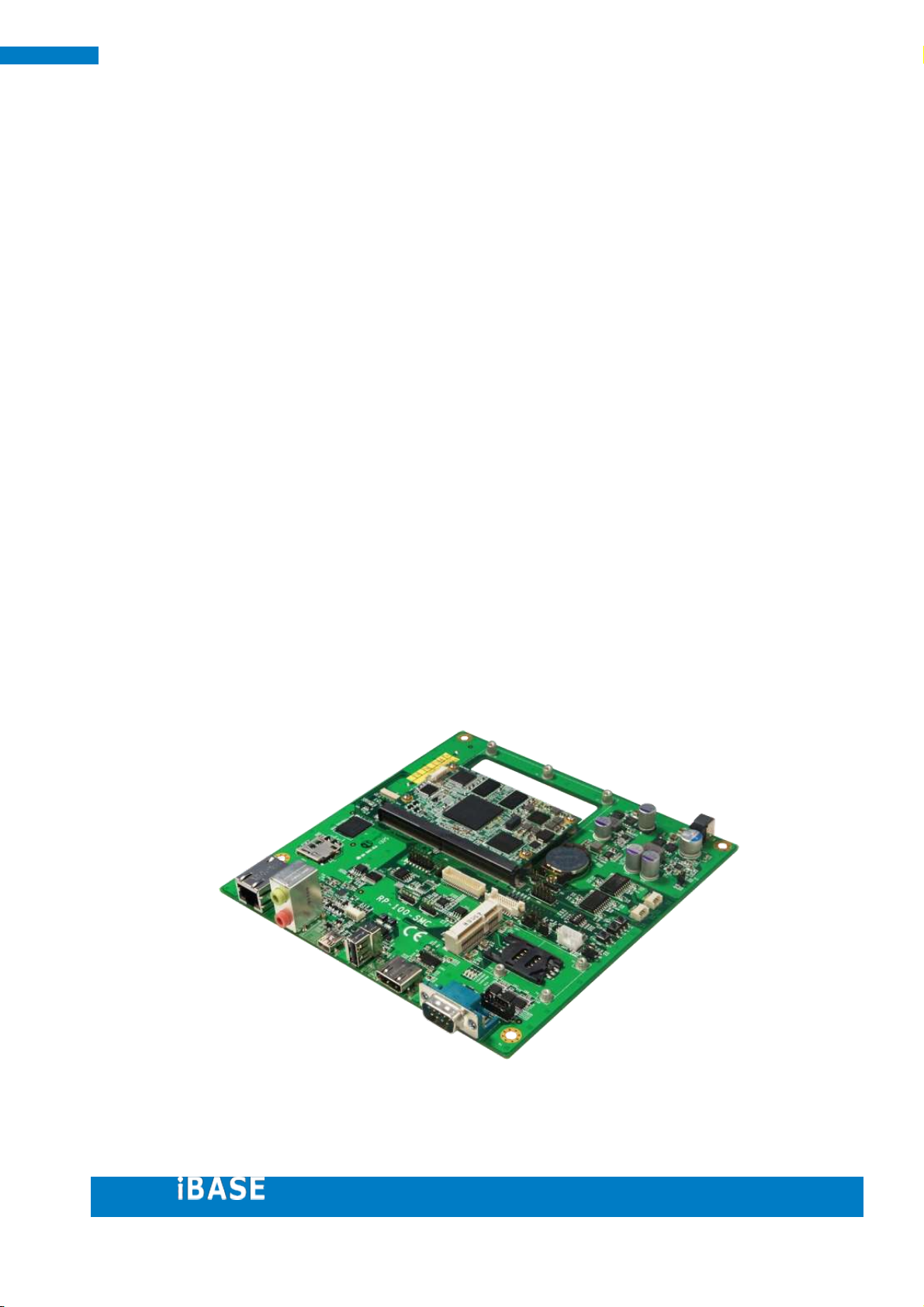
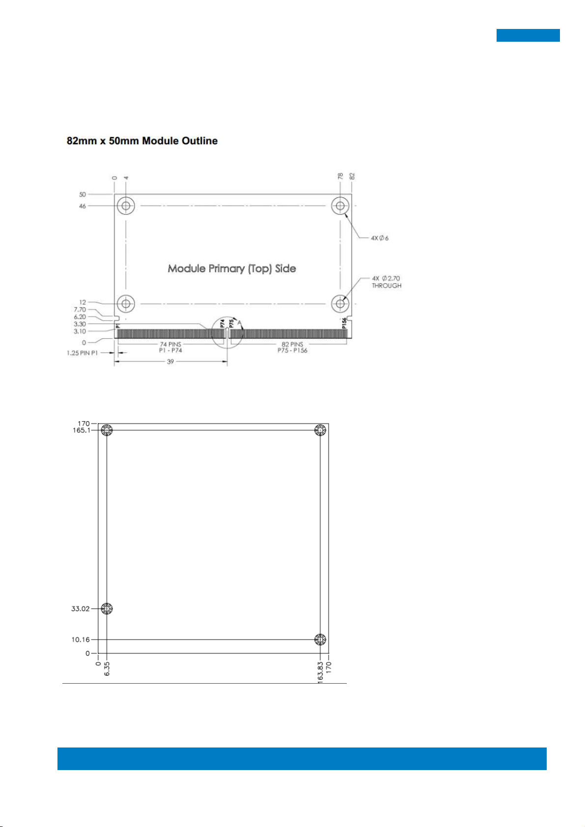
Measuring 82mm x 50mm, the Ibase RM-F600-SMC SMARC module is integrated
with an i.MX6 Dual Lite 1Ghz extended consumer-grade CPU that supports 2D/3D
graphic acceleration and 1080p encode/ decode under Linux/Android BSP to allow easy
OS upgrade and short time to market.
Measuring 170mm x 170mm (Mini ITX form factor), the Ibase RP-100-SMC carrier
board is compatible with 82mm x 50mm - 82mm x 80mm standard SMARC form factors.
Engineers can choose the required embedded IOs to verify developed software
application under specified Operation System. Besides setting the default HDMI output
with O.S preload in RM-F600-SMC eMMC, IBASE can optionally provide driver-ready 3G
module, WIFI module, touch panel, cable kit, power adaptor and accessories to speed
up the evaluation cycle.
Page 8
Copyright © 2013 IBASE Technology Inc. All Rights Reserved. 8
8
SMARC Evaluation Kit
Form Factor
SMARC™ (82mm x 50mm)
CPU
Freescale i.MX6 DualLite Cortex-A9
Up to 1GHz with 512KB L2 cache
Memory
1GB DDR3 on board
4GB eMMC on board
Display
Supports 18/24-bit parallel LCD & LVDS Interface
Supports HDMI Interface
Video Codec
Multi-format HD1080 video Decode and Encode
Audio Interface
I²S, SPDIF
LAN
10/100/1000 Mbit/sec
USB
2 x USB 2.0 port & 1x USB OTG Interface
Image Capture Interface
CSI Interface for MIPI Camera
Serial
4x UART, 1x SPI Interface
Media Interface
2 x High-Speed MMC/SDIO (MMC 8-bit, SDIO 4-bit)
PCIe
1x PCIe Interface
GPIO
12x GPIO
I²C
4x I²C
CAN Bus
2x CAN2.0B
Operating Temperature
Extended commercial: 0°C to +60°C @1Ghz
Board Connector
MXM3.0 314 pins
Operating System
Supports Linux Kernel 3.0, Android 4.3
1.2. RM-F600-SMC Hardware Specifications
RM-F600-SMC Features
SMARC Small Form Factor (82mm x 50mm) SoM
i.MX 6DualLite 1GHz Processor
1080p hardware encode/decode
OpenGL ES 2.0 and OpenVG 1.1 hardware accelerators
1GB DDR3, 4GB eMMC on board
10/100/1000 MBit Ethernet
Supports 24-bit Parallel LCD, LVDS, & HDMI
Supports Linux 3.0, Android 4.3
‧
This specification is subject to change without prior notice.
Page 9
9
9
IBASE Technology Inc.
Form Factor
Standard Mini-ITX (170mm x 170mm)
Edge IO
1x GB LAN
1x headphone
1x MIC
2x USB
1x USB OTG
1x HDMI
1x COM (232/422/485)
Internal Headers /
Connectors
2x CAN
1x parallel LCD
1x Single CH, 18/24 bit LVDS
1x LCD DDC (I2C)
1x LCD backlight power control header
1x CSI-MIPI
2x USB 2.0
8x GPIO
1x 2COM ports header
1x debug port
1x Mini-PCIe with USB
1x SIM socket
1x touch (4-wired)
1x speaker Out
1x micro-SD
Jumpers, Switch &
Buttons
1x boot select switch (SD/ eMMC)
1x reset button, 1x power button, 1x GPI button
1x (232/422/485 Selection) jumper
1x backlight power (5/12V) jumper
RP-100-SMC – Carrier Board Specifications
RP-100-SMC Features
For SMARC form factor modules
12V~24V DC-in, reset, power, RTC function
Supports GB LAN, audio, USB OTG, HDMI, COM (232/422/485) @ Edge IO
Micro SD socket, Mini-PCIe with USB, SIM socket on board
2x isolated CAN transceiver, TTL, LVDS, HDMI, CSI-MIPI camera
Specifications
‧
This specification is subject to change without prior notice.
Page 10
Copyright © 2013 IBASE Technology Inc. All Rights Reserved. 10
10
SMARC Evaluation Kit
1.3. Boards Dimension
RM-F600-SMC Dimensions
RP-100-SMC (MiniITX) 170mm x 170mm
Page 11
11
11
IBASE Technology Inc.
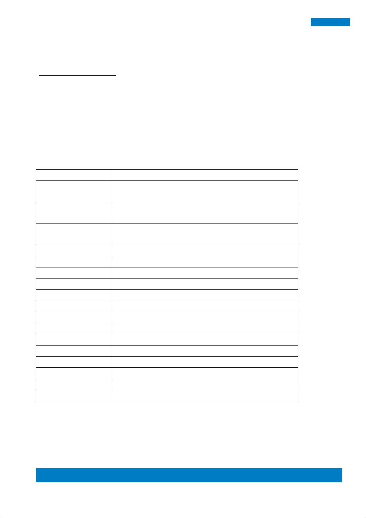
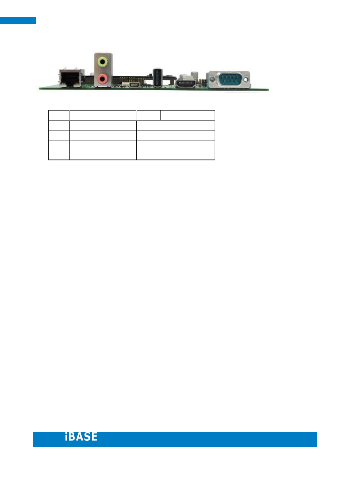
Item
Connector
Item
Connector
1
10/100/1000 LAN
5
HDMI Type A
2
Audio Jack
6
RS232/422/485
3
USB OTG
7 4
USB Type A
8
1.4. I/O View
Page 12
Copyright © 2013 IBASE Technology Inc. All Rights Reserved. 12
12
SMARC Evaluation Kit
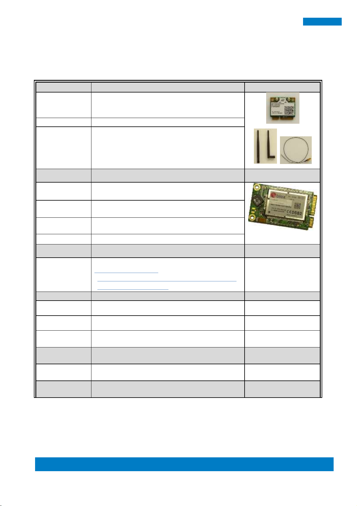
WIFI Solution
Description
Note
WiFi module
Wireless LAN Card; 802.11 B/G/N card RoHS
RTL8188CTV-SC5X (5VDC)
(A008LANMIPCIE4100P)
External Antenna
Wifi Antenna (A055RFA02C2M20800P)
Internal cable-1/2
From Wifi module to rear/front panel
(A055RFA0000021000P/A055RFA0000032000P)
3G Solution
Description
ZU 202
Wireless; 3.75G UMTS/HSPA [ZU202] RoHS
(A008WIRELESS00520P)
ZU 200
Wireless; 3.75G UMTS/HSPA & GPS module
[ZU200] RoHS (A008WIRELESS00510P)
Cable
Cable; Antenna-2 30CM P 2pcs (C501ANT0200300000P)
Antenna
Antenna; 3G, P, 2pcs (A055ANT0921Q2P000P)
COM Port Cable
Description
COM & debug cable
Cable; for internal 3x COM ports box header
COM 1 for debug console:
- User can make your own debug cable too by checking
Ch3.2.1 and CN15 connector.
C501PK19100204000P
Power & LCD
Description
Adaptor
12V, Power Adaptor
A005PS060WFSP0101P
LCD
10 inch. 1280 x 800 LCD
A003LCD0101010300
LCD cable.
LCD312 Cable
C501LCD3120302000P
BT solution
Description
BSLIM2 A10
BLUETOOTH 4.0 BOARD
A008BTBSLIM201000P
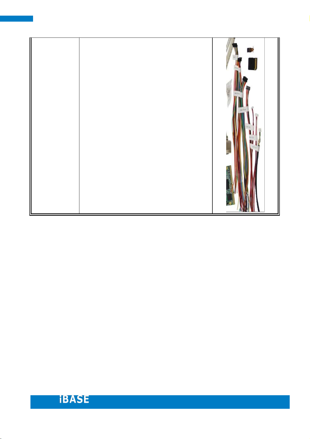
Cable kit
Description
1.5. Optional Items
If you have further request for option items, please contact iBASE sales.
Page 13
13
13
IBASE Technology Inc.
For carrier board
USB-29 (C501USB2908303000P): USB 2.0 (USB1)
EXT-458 (C501EXT4580301000P): Audio Speaker
(CN14)
EXT-459 (C501EXT4590301000P): RS232 (CN15)
EXT-460 (C501EXT4600301000P): LCD DDC DATA/CLK
(CN6)
EXT-461 (C501EXT4610301000P): Touch (CN13)
EXT-462 (C501EXT4620301000P): SPI (CN7)
EXT-463 (C501EXT4630301000P): GPIO (CN5)
EXT-464 (C501EXT4640301000P): CAN Bus (J2, J4)
Others:
500Mega pixel MIPI Camera (A033MODULE0200000P):(J3)
Page 14

Copyright © 2013 IBASE Technology Inc. All Rights Reserved. 14
14
SMARC Evaluation Kit
1.6. Installing the SMARC
The MXM3.0 connector on RP-100-SMC supports the SMARC form factor (82mm x
50mm and 82mm x 70mm).
To install SMARC modules to the MXM slot on the board, please perform the
following steps:
Hold the SMARC module so that the golden fingers of the SMARC module
aligned with the MXM connector.
Gently push the SMARC module to the MXM connector in 45 degree angle
position until the golden finger of SMARC completely touch the bottom of the
slot.
Gently press the SMARC module down and fix it with four screws.
Page 15
15
15
IBASE Technology Inc.
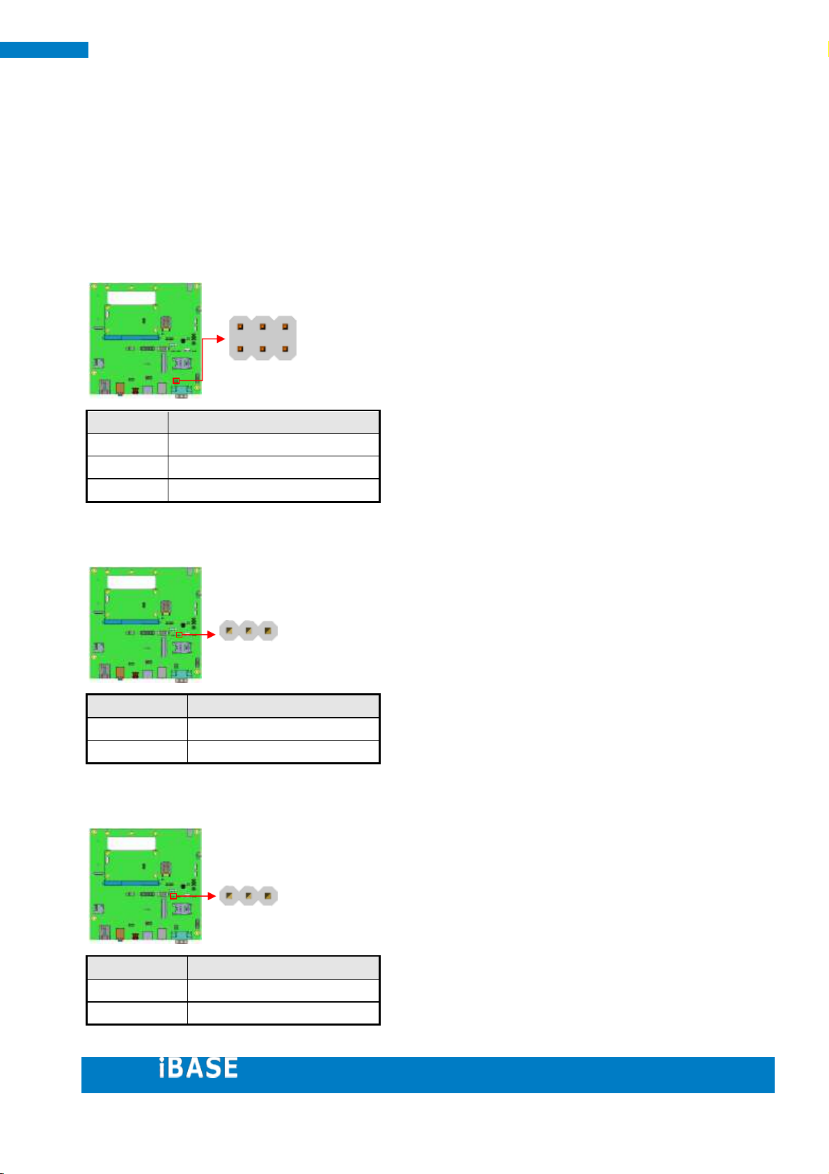
Mode
Jumper Setting
RS232
2-4, 3-5 Shorted (Default)
RS422
3-5, 4-6 Shorted
RS485
1-3, 4-6 Shorted
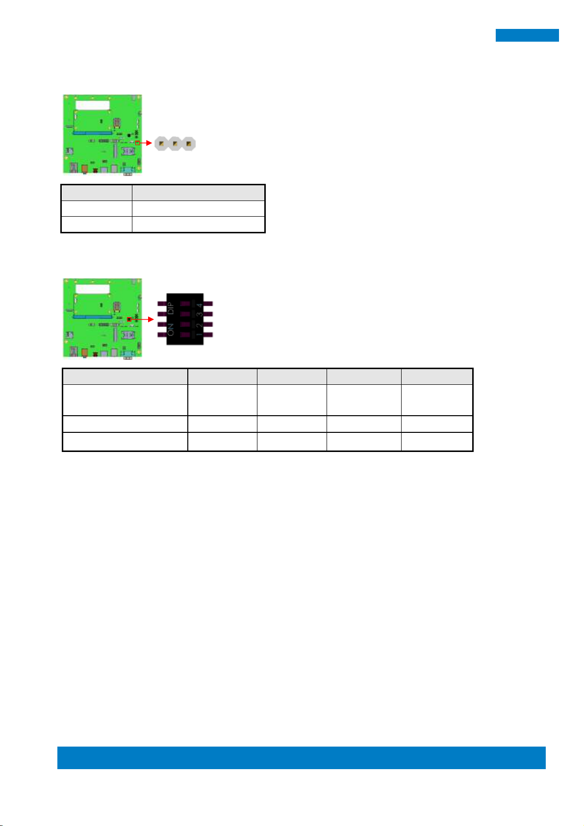
LCD_VDD
Jumper Setting
3.3V
2-3 Shorted (Default)
5V
1-2 Shorted
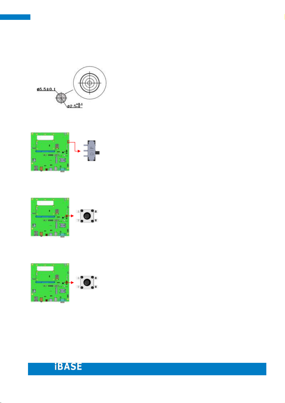
BKLT_VCC
Jumper Setting
5V
1-2 Shorted (Default)
12V
2-3 Shorted
6
5
1
1
2. Jumper setting on the Carrier Board
[Important] Please check the jumpers, DIP, buttons and switches on
RP-100-SMC before doing the panel connection and boot up.
JP3: Setting Jumper for CN17 (RS232/422/485)
J7: LCD_VDD Select
J6: BKLT_VCC Select
Page 16
Copyright © 2013 IBASE Technology Inc. All Rights Reserved. 16
16
SMARC Evaluation Kit
BKLT_PWM
Jumper Setting
3.3V
2-3 Shorted (Default)
5V
1-2 Shorted
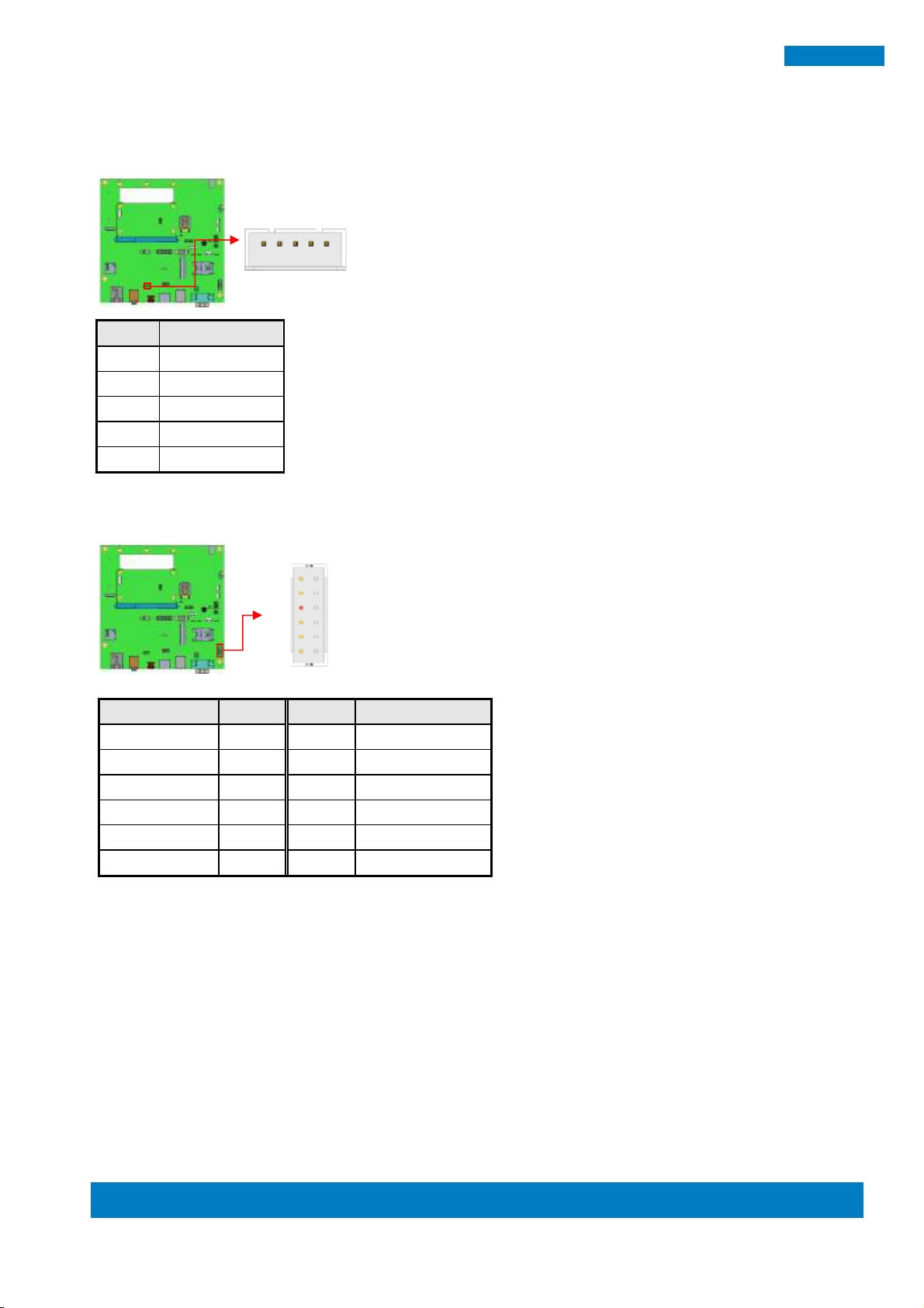
Boot Source
SW3_PIN1
SW3_PIN2
SW3_PIN3
SW3_PIN4
Carrier SATA
(i.MX6 Dual/ Quad only)
1 1 1
X
Carrier SD
0 1 1
X
Module eMMC ( default)
1 0 0
X
1
J8: BKLT_PWM Select
SW3: Boot Select
Page 17
17
17
IBASE Technology Inc.
CN1: DC Power Jack.
(CN1’s mating Connector.)
SW5: +5V ON/OFF
SW1: Power Button
SW2: Reset Button
Page 18
Copyright © 2013 IBASE Technology Inc. All Rights Reserved. 18
18
SMARC Evaluation Kit
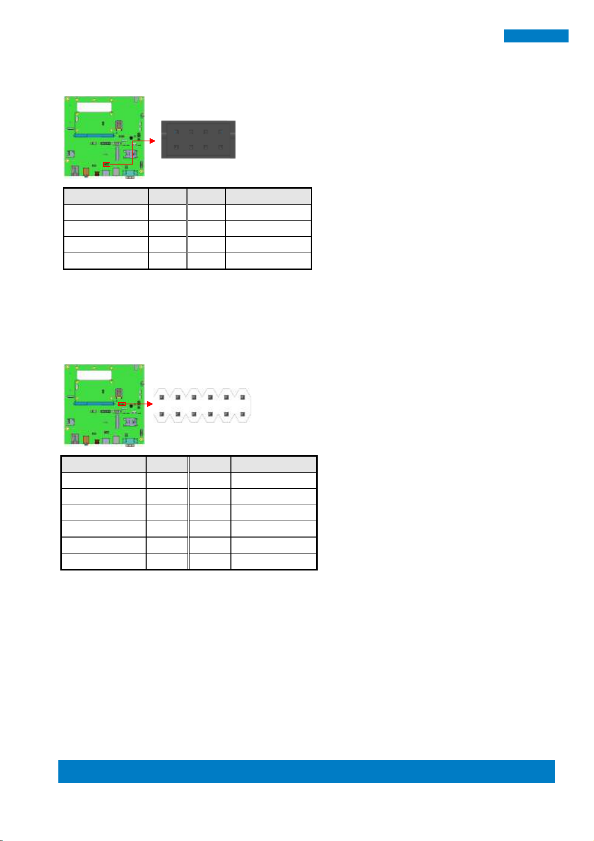
Pin #
Signal Name
1
SPKL+
2
SPKL-
3
GND
4
SPKR-
5
SPKR+
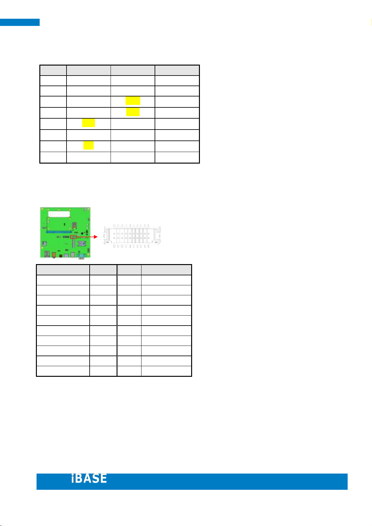
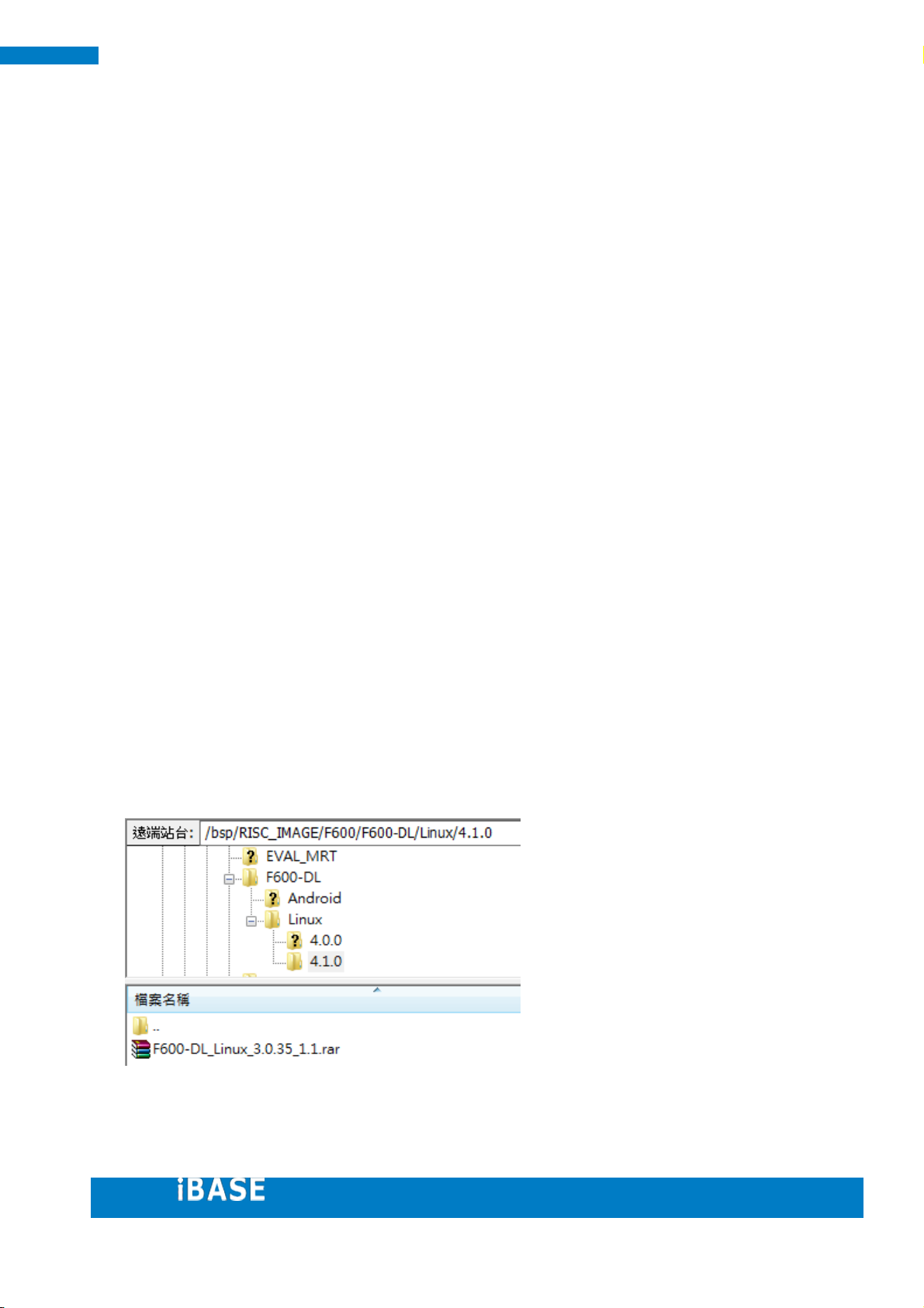
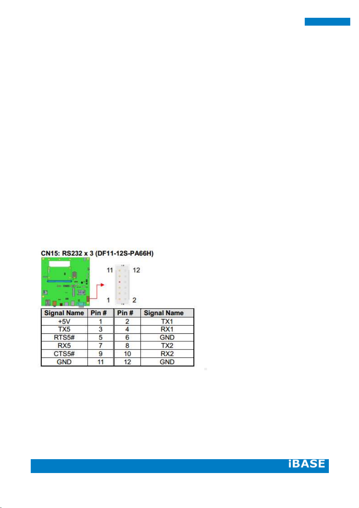
Signal Name
Pin #
Pin #
Signal Name
+5V
1 2 TX1
TX5
3 4 RX1
RTS5#
5 6 GND
RX5
7 8 TX2
CTS5#
9
10
RX2
GND
11
12
GND
5
12 11
Connectors on RP-100-SMC
CN14: Audio Speaker Out (E-CALL_0110-26110050)
CN15: RS232 x 3 (DF11-12S-PA66H)
Page 19
19
19
IBASE Technology Inc.
Pin #
RS232
RS422
RS485
1 TXD-
D- 2 RXD
TXD+
D+
3
TXD
RXD+
4 RXD-
5
GND
6
7
RTS
8
CTS
Signal Name
Pin #
Pin #
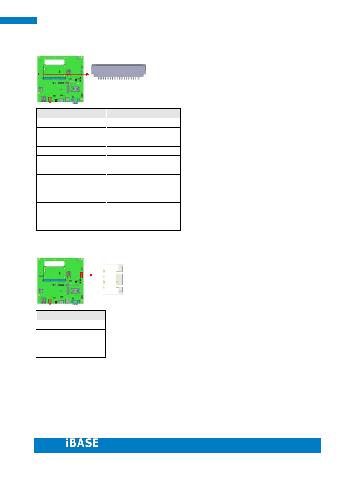
Signal Name
TX0+
1 2 TX0-
GND
3 4 GND
TX1+
5 6 TX1-
GND
7 8 VDD
TX3+
9
10
TX3-
TX2+
11
12
TX2-
GND
13
14
GND
TXC+
15
16
TXC-
BKLT_PWM
17
18
VDD
BKLT_VCC
19
20
BKLT_VCC
19
20
CN17: RS232/422/485
( SMARC standard define 4 wired RS232 signals)
N9: LVDS (DF13-20DP-1.25V)
Page 20
Copyright © 2013 IBASE Technology Inc. All Rights Reserved. 20
20
SMARC Evaluation Kit
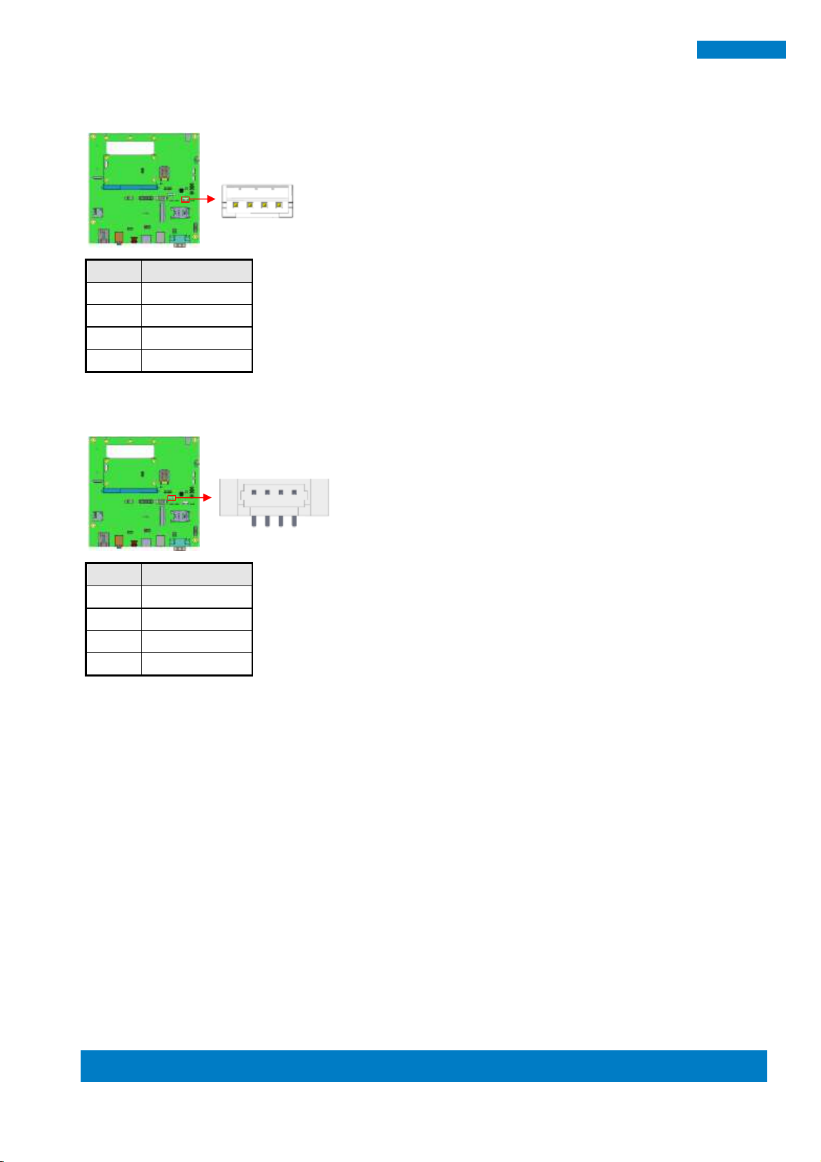
Pin #
Signal Name
1
BKLT_VCC
2
BKLT_EN
3
BKLT_PWM
4
GND
Pin #
Signal Name
1
+5V
2
I2C_SCL
3
I2C_SDA
4
GND
4
4
CN10: LCD Backlight Power/Control (E-CALL 0110-161-040)
CN6: LCD DDC CLK/DATA (Molex 53398-0471)
Page 21
21
21
IBASE Technology Inc.
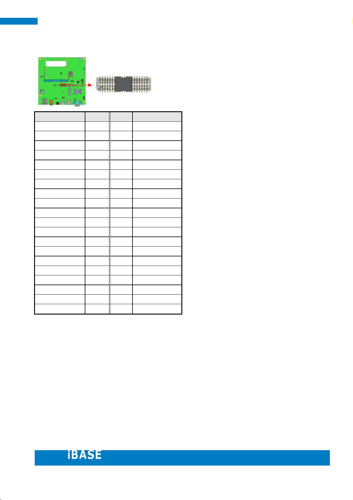
Signal Name
Pin #
Pin #
Signal Name
LCD_VDD
1 2 LCD_VDD
GND
3 4 GND
LCD_VDD
5 6 LCD_VDD
BKLT_PWM
7 8 GND
DAT16
9
10
DAT17
DAT18
11
12
DAT19
DAT20
13
14
DAT21
DAT22
15
16
DAT23
DAT8
17
18
DAT9
DAT10
19
20
DAT11
DAT12
21
22
DAT13
DAT14
23
24
DAT15
DAT0
25
26
DAT1
DAT2
27
28
DAT3
DAT4
29
30
DAT5
DAT6
31
32
DAT7
GND
33
34
GND
CLK
35
36
VSYNC
DE
37
38
HSYNC
BLON
39
40
PWR_EN
2
1
JP2: TTL LCD (E-CALL 0110-01-53101400)
Page 22

Copyright © 2013 IBASE Technology Inc. All Rights Reserved. 22
22
SMARC Evaluation Kit
Pin #
Signal Name
1
X+ 2 X- 3 Y+ 4 Y-
Signal Name
Pin #
Pin #
Signal Name
+3.3V
1 2 +3.3V
NC
3 4 NC
SPI1_CS1#
5 6 SPI2_CS1#
SPI1_MISO
7 8 SPI2_MISO
SPI1_CLK
9
10
SPI2_CLK
SPI1_MOSI
11
12
SPI2_MOSI
GND
13
14
GND
1
2
1
CN13: Touch (E-CALL 0195-01-200-040)
CN7: SPI (E-CALL 0196-01-251-140)
Page 23
23
23
IBASE Technology Inc.
Signal Name
Pin #
Pin #
Signal Name
GND
1 2 +2.8V
NC
3 4 NC
GND
5 6 D1+
D1-
7 8 CLK+
CLK-
9
10
D0+
D0-
11
12
NC
NC
13
14
RST#
NC
15
16
NC
NC
17
18
SDA
SCL
19
20
PWR#
MCLK
21
22
NC
+1.8V
23
24
+2.8V
Pin #
Signal Name
1
CANH
2
GND_ISO
3
CANL
4
GND_SHIELD
24
4
J3: CSI (TECHBEST 7080K-F24N-24R)
J2, J4: CAN BUS (E-CALL 0110-2620040)
Page 24
Copyright © 2013 IBASE Technology Inc. All Rights Reserved. 24
24
SMARC Evaluation Kit
Signal Name
Pin #
Pin #
Signal Name
+5V
1 2 GND
USB1_D-
3 4 USB2_D+
USB1_D+
5 6 USB2_D-
GND
7 8 +5V
Signal Name
Pin #
Pin #
Signal Name
+3.3V
1 2 GPIO3
GPIO1
3 4 GPIO7
GPIO5
5 6 GPIO9
GPIO8
7 8 RESET#
GPIO10
9
10
WDOG#
GPIO11
11
12
GND
8
7
2
1
USB1: USB x 2 (DF11-8DP-2DSA)
Mating Cable: USB-29, (C501USB2908303000P)
CN5: GPIO (E-CALL 0196-01-200-120)
Page 25
25
25
IBASE Technology Inc.
3. Software Setup
Users who has Ibase standard image file can refer to this chapter to prepare your own
boot-up SD card. Ibase provides HDMI / LVDS output environment by default to let you
prepare the software application pre-development easily under Linux / Android
platform.
3.1. Make a Recovery SD Card
Preparing your Recovery SD card help to install the Linux/ Android image into eMMC
Please download the Recovery SD card’s image by FTP in advance.
Host: 219.87.145.180 port: 21
User: bsp
Password: (please check with your sales)
Image path:
/bsp/RISC_IMAGE/F600/F600-DL/Linux/4.1.0/F600_ubuntu_v1.1.img.gz
/bsp/RISC_IMAGE/F600/F600-DL/Android/4.3/F600-DL_Android_4.3_1.1.img.rar
(based on Freescale BSP: L3.3.35.4.1.0)
For example:
Page 26
Copyright © 2013 IBASE Technology Inc. All Rights Reserved. 26
26
SMARC Evaluation Kit
In order to use the evaluation kit, you will need to install an Operating System (OS) onto
onboard eMMC by recovery SD card. An Operating System is the set of basic programs
and utilities that allow your computer to run.
These instructions will guide you through installing a recovery program on your SD card
that will allow you to easily install different OS’s and to recover your card when needed.
1. Insert an SD card that is 4GB or greater in size into your computer
2. Format the SD card
i. Download the SD Association's Formatting Tool (SD Card Formatter 4.0 ) from
https://www.sdcard.org/downloads/formatter_4/eula_windows/
ii. Install and run the Formatting Tool on your machine
iii. Set "FORMAT SIZE ADJUSTMENT" option to "ON" in the "Options" menu
iv. Check that the SD card you inserted matches the one selected by the Tool
v. Click the “Format” button
3. Download the target operating system image from the DVD/ or FTP
(Descripted in previous page)
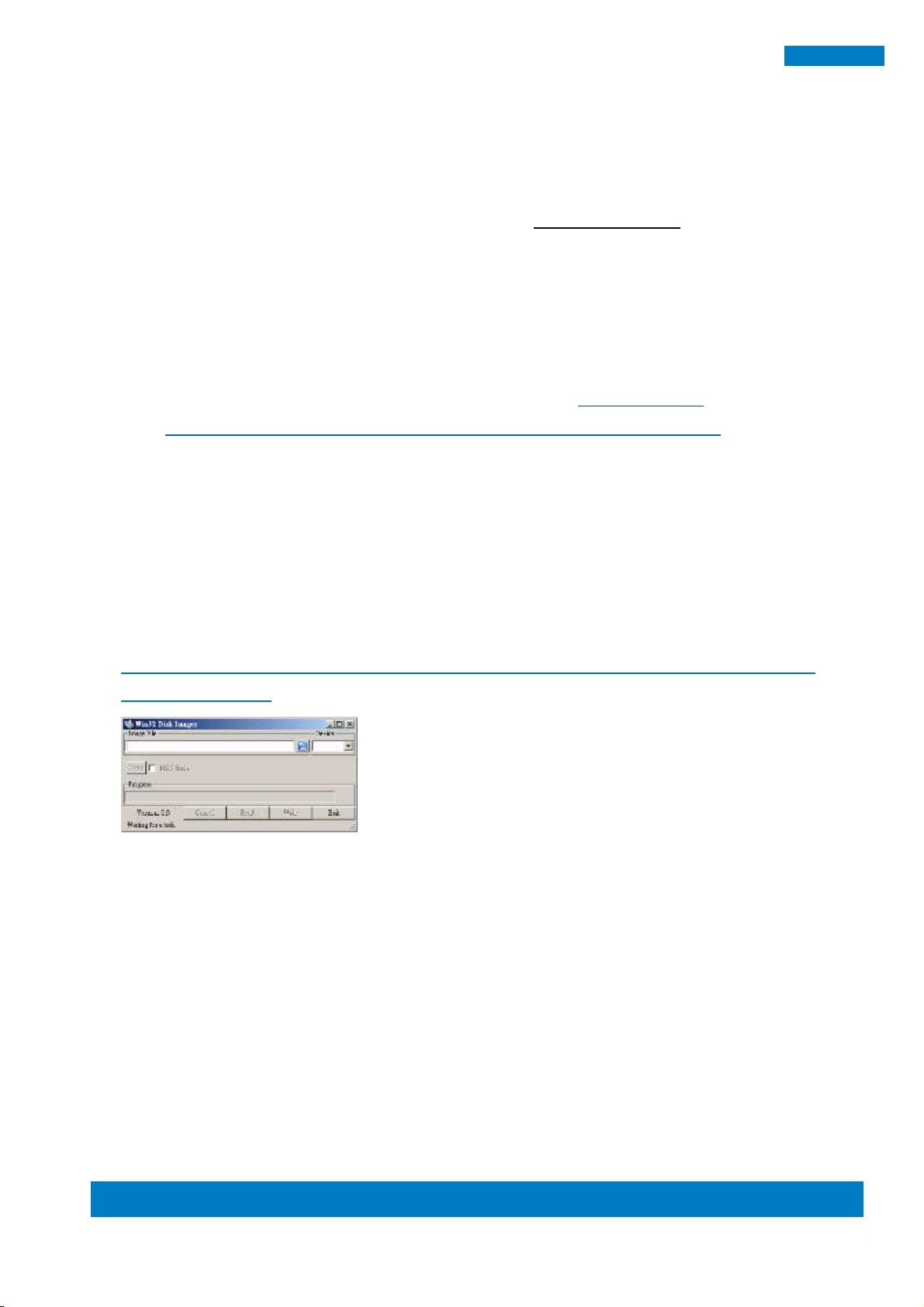
4. Download the Win32DiskImager from
http://sourceforge.net/projects/win32diskimager/ and use it to restore the target
operating system.
And then, flash the Android/ Linux image into your SD card in your PC (Windows).
6. Please check the DIP switch and make sure it can boot from SD Card.
(See 2.3 Boot on the SMARC starter kit )
Page 27
Copyright © 2013 IBASE Technology Inc. All Rights Reserved.
1
IBASE Technology Inc.
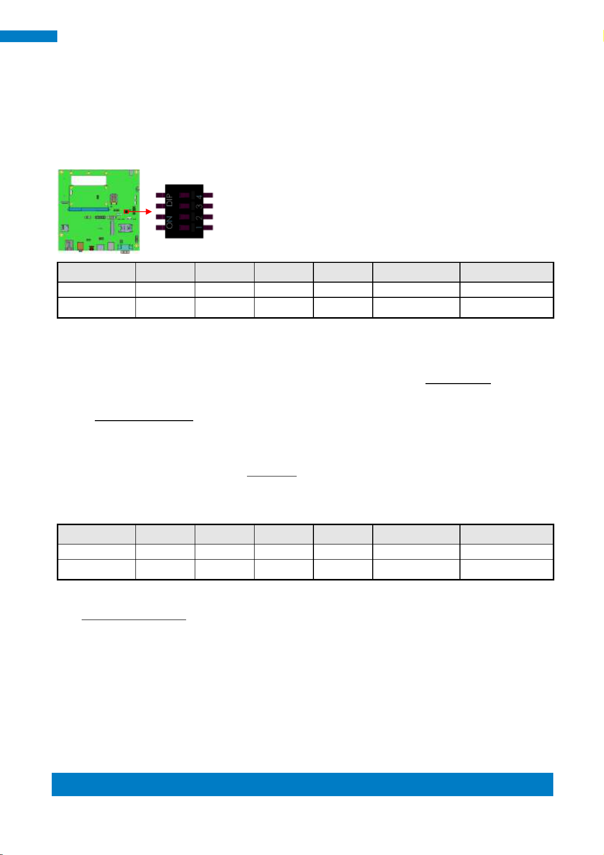
Boot Source
SW3_PIN1
SW3_PIN2
SW3_PIN3
SW3_PIN4
Linux node name
Android node name
Carrier SD
0 1 1
X
Module eMMC
1 0 0
X
Boot Source
SW3_PIN1
SW3_PIN2
SW3_PIN3
SW3_PIN4
Linux node name
Android node name
Carrier SD
0 1 1
X
Module eMMC
1 0 0
X
3.2. Boot on the SMARC starter kit
Please double check the Boot device selection before power on.
SW3: Boot Select
Note: 1: Switch On ; 0: Switch Off
1. 7. Insert the SD card/MicroSD into motherboard, make sure the HDMI panel is
connected, and connect the power supply to boot up the system.
2. 8. Recovery program on your SD card will execute automatically. The eMMC on
SMARC will be format, and OS will be installed while the progress bar shows 100%
complete.
3. 9. Remove the power, and the recovery SD. Remember to set the boot source
from module eMMC.
4. Connect the power and boot up SMARC, you will see the Linux/ Android boot up
pages.
Page 28
2
SMARC Evaluation Kit
3.3. Parameter Setting on U-boot
We provide HDMI output and (10.1 “ Onation LVDS Panel output command example)
for SMARC starter kit. If you have any other LVDS/ TTL panel need to be customized,
please contact Ibase sales or FAE staff.
3.3.1. Preparation (debug console)
i. We set the COM1 (Tx1, Rx1) as default debug port, please double check it can be
connect to (RX, Tx) of your PC environment.
ii. set 115200 bps (8n1, no flow control) in Windows terminal ( for example
Putty.exe)
iii. When booting the system, you can press “Enter” to stop auto boot and modify
your environment.
(Note: Users who are not sure the COM connection, please double check your
SMARC.COM1.Tx1 connect to PC.COM.Rx ; SMARC.COM1.Rx1 to PC.COM.Tx)
Note:
The COM1 is map to ttymxc0 device node under Linux& android.
The COM2 is map to ttymxc1 device node under Linux& android.
The COM5 is map to ttymxc4 device node under Linux& android.
Page 29

Copyright © 2013 IBASE Technology Inc. All Rights Reserved.
3
IBASE Technology Inc.
MX6SDL SABREDS U-BOOT > setenv bootcmd “booti mmcX”
setenv bootargs 'console=ttymxc0,115200 androidboot.console=ttymxc0
androidboot.hardware=freescale init=/init ldo_active=on vmalloc=400M
video=mxcfb0:dev=ldb,OT101-XGA,bpp=32 ldb=sep0 video=mxcfb1:dev=hdmi,1280x720M@60
video=mxcfb2:off fbmem=15M,28M'
setenv bootargs 'console=ttymxc0,115200 androidboot.console=ttymxc0
androidboot.hardware=freescale init=/init ldo_active=on vmalloc=400M
video=mxcfb0:dev=ldb,OT101-XGA,bpp=32 ldb=sep0 video=mxcfb1:off video=mxcfb2:off
fbmem=15M'
setenv bootargs 'console=ttymxc0,115200 androidboot.console=ttymxc0
androidboot.hardware=freescale init=/init ldo_active=on vmalloc=400M
video=mxcfb0:dev=hdmi,1280x720M@60 video=mxcfb1:off video=mxcfb2:off fbmem=28M'
MX6SDL SABREDS U-BOOT > saveenv
MX6SDL SABREDS U-BOOT > boot
3.3.2. Display setting command For Android
Select boot device:
Where mmcX =1, means boot from Carrier’s SD card.
Where mmcX =2, means boot from SMARC module’s eMMC device.
Command to set HDMI+OT101 LVDS panel:
Command to set OT101 10.1” LVDS panel:
Command to set HDMI output:
( please also save the environment and reboot by following command)
Page 30

4
SMARC Evaluation Kit
setenv bootargs_mmc 'setenv bootargs ${bootargs} root=/dev/mmcblk0p1 rootwait ldo_active=on
rw video=mxcfb0:dev=ldb,OT101-XGA,if=RGB666 ldb=sep0 rootfstype=ext4'
setenv bootargs_mmc 'setenv bootargs ${bootargs} root=/dev/mmcblk0p1 rootwait ldo_active=on
rw video=mxcfb0:dev=hdmi,1280x720M@60 fbmem=28M rootfstype=ext4'
Carrier SD : root=/dev/mmcblk1p1
3.3.3. Display setting for Linux
Command to set OT101 10.1” Panel:
Command to set HDMI output:
Command to Set the boot device
Note: (remember to save the environment and reboot by following command)
MX6SDL SABREDS U-BOOT > saveenv
MX6SDL SABREDS U-BOOT > boot
Page 31

Copyright © 2013 IBASE Technology Inc. All Rights Reserved.
5
IBASE Technology Inc.
LVDS
DDR3
1GByte
SD2/ SDIO
HDMI
I2C x4
SPI x2
CPLD
MAX3064
24bit LCD
USB_HUB
UPD720114
USB_OTG
SPDIF x1
I2S x1
SD4/ eMMC
eMMC
KLM4G1FE3B/4GB
PHY
AR8031
USB x2USB
CSI x1
GB_LANRGMII
Freescale
i.MX6
Processor
UART x4
CAN x2
Watch_DOG x1
SATA x1
PCIe x1
GPIO x12
Boot select
ULP-COM
Golden Finger
(Dual/Quad)
SD3
4. Carrier Board Design Guide
This Chapter mainly for advanced EE to create your own carrier boards (or products), layout suggestion
can be found inside also. for RP-100-SMC carrier board design schematic file. Please contact your sales
in advance.
4.1. Block Diagram
Page 32

6
SMARC Evaluation Kit
Pin
Signal Name
I/O
Type
Power Rail
Description
P83
PCIE_CLK1P
O
PCIe
Differential PCIe reference clock output
P84
PCIE_CLK1N
O
PCIe
P89
PCIE_TXP
O
PCIe
Differential PCIe transmit data pair
P90
PCIE_TXM
O
PCIe
P86
PCIE_RXP
I
PCIe
Differential PCIe receive data pair
P87
PCIE_RXM
I
PCIe
S146
PCIE_WAKE#
I
CMOS
3.3V
PCIe wake up signal
P75
PCIE_RST#
O
CMOS
3.3V
PCIe reset output
S49
I2C4_SDA
I/O
OD
3.3V
I2C interface data, some PICe device need SMB interface for
special configuration
S48
I2C4_SCL
O
OD
3.3V
I2C interface clock, some PICe device need SMB interface for
special configuration
C80 0.1UF/ 25V/4
C62 0.1UF/ 25V/4
C87 0.1UF/ 25V/4
R58 10K/4
+3.3V_VCC
UIM_VPP
UIM_DATA
PCIE_WAKE#13
C61 0.1UF/ 25V/4
+3.3V_VCC
C83 0.1UF/ 25V/4
C78 0.1UF/ 25V/4
KEY
J9
FOXCONN_AS0B226-S99Q-7H
WAKE#
1
RSVD1
3
RSVD2
5
CLKREQ#
7
GND1
9
REFCLK-
11
REFCLK+
13
GND2
15
RSVD3
17
RSVD4
19
GND3
21
PER_N0
23
PER_P0
25
GND4
27
GND5
29
PET_N0
31
PET_P0
33
GND6
35
RSVD5
37
RSVD6
39
RSVD7
41
RSVD8
43
RSVD9
45
RSVD10
47
RSVD11
49
RSVD12
51
+3V_1
2
GND7
4
+1.5V_1
6
RSVD13
8
RSVD14
10
RSVD15
12
RSVD16
14
RSVD17
16
GND8
18
RSVD18
20
PERST#
22
+3V_AUX
24
GND9
26
+1.5V_2
28
SMB_CLK
30
SMB_DATA
32
GND10
34
USB_D-
36
USB_D+
38
GND11
40
LED_WWAN#
42
LED_WLAN#
44
LED_WPAN#
46
+1.5V_3
48
GND12
50
+3V_2
52
GND
57
GND
58
+3.3V_VCC
LED3 LTST-C190KGKT_GRN
C A
+1.5_VCC
LED2 LTST-C190KGKT_GRN
C A
LED_WLAN#
+3.3V_VCC
C89 0.1UF/ 25V/4
+3.3V_VCC
LED_WPAN#
LED4 LTST-C190KGKT_GRN
C A
UIM_VPP
UIM_DATA
+1.5_VCC
+3.3V_VCC
UIM_RST
UIM_CLK
UIM_PWR
R90 330/4
LED_WWAN#
LED_WPAN#
LED_WLAN#
+1.5_VCC
+1.5_VCC
R89 330/4
UIM_RST
UIM_CLK
UIM_PWR
R88 330/4
C85 4.7UF/ 16V/6
I2C4_SDA 8,13
+3.3V_VCC
PCIE_RXM13
PCIE_TXM13
PCIE_CLK1_N13
PCIE_TXP13
PCIE_RXP13
PCIE_RST# 13
PCIE_CLK1_P13
I2C4_SCL 8,13
LED_WWAN#
C65 4.7UF/ 16V/6
DOWN_USB_PA2+ 13
DOWN_USB_PA2- 13
J10
WIN W ING_WSC D-06ACP1U4
VCC
1
RESET
2
CLK
3
GND
4
VPP
5
I/O
6
4.2. Interfaces
4.2.1. PCI Express
PCIe Signals
Reference Schematic
*Notice* : SMARC PINS48~PINS49 are I2C4, which is activated in RM-F6SO-SMC and RM-F600-SMC
module only. Users who need to adopt I2C in RM-F6DU-SMC or RM-F6QD-SMC, please connect it from
I2C1~I2C3 in the carrier board.
Page 33

Copyright © 2013 IBASE Technology Inc. All Rights Reserved.
7
IBASE Technology Inc.
Page 34

8
SMARC Evaluation Kit
Pin
Signal Name
I/O
Type
Power Rail
Description
P48
SATA_TP
O
SATA SATA transmit data positive
P49
SATA_TN
O
SATA SATA transmit data negative
P51
SATA_RP
I
SATA SATA receive data positive
P52
SATA_RN
I
SATA SATA receive data negative
C138
0.1UF/25V/4
C137
0.1UF/25V/4
+3.3V_VCC
CN22
WINNING_WATB-22DL1P3U
TX
S2
TX#
S3
RX#
S5
RX
S6
VCC3_0
P1
VCC3_1
P2
VCC3_2
P3
VCC5_0
P7
VCC5_1
P8
VCC5_2
P9
VCC12_0
P13
VCC12_1
P14
VCC12_2
P15
RESVE
P11
GND0
S1
GND1
S4
GND2
S7
GND3
P4
GND4
P5
GND5
P6
GND6
P10
GND7
P12
NC0
H1
NC1
H2
SATA_RXP13
SATA_TXP13
SATA_TXN13
SATA_RXN13
RS8
Short PAD6
+5V_VCC
+12V_VCC +12V_SATA
+3.3V_VCC
+5V_VCC
C140
0.1UF/25V/4
C141
0.1UF/25V/4
C142
0.1UF/25V/4
C139
0.1UF/25V/4
4.2.2. SATAII
SATAII Signals
Reference Schematic
Page 35

Copyright © 2013 IBASE Technology Inc. All Rights Reserved.
9
IBASE Technology Inc.
Pin
Signal Name
I/O
Type
Power Rail
Description
P65
DOWN_USB_PA1+
I/O
USB Positive differential USB host signal
P66
DOWN_USB_PA1-
I/O
USB Negative differential USB host signal
P67
H2_USB_OC#1
I/O
OD
3.3V
Over current input signal
Pin
Signal Name
I/O
Type
Power Rail
Description
P69
DOWN_USB_PA2+
I/O
USB Positive differential USB host signal
P70
DOWN_USB_PA2-
I/O
USB Negative differential USB host signal
P71
H2_USB_OC#2
I/O
OD
3.3V
Over current input signal
Pin
Signal Name
I/O
Type
Power Rail
Description
P60
USB_OTG_DP
I/O
USB Positive differential USB host signal
P61
USB_OTG_DN
I/O
USB Negative differential USB host signal
P62
USB_OTG_OC#
I/O
OD
3.3V
Over current input signal
P63
USB_OTG_VBUS
O
SATA
5V
SATA transmit data negative
P64
USB_OTG_ID
I
SATA
3.3V
SATA receive data positive
USB2_CN_DP
USB2_CN_DN
+5V_VBUS1
+5V_VBUS2
USB2_CN_DP
USB2_CN_DN
DOWN_USB_PA2+
DOWN_USB_PA2-
LM9
ACM2012-900-2P
2
3
1
4
USB2_CN_DP
USB2_CN_DN
USB1
HRS_DF11-8DP-2DSA(08)
2
4
6
8
1
3
5
7
+5V_VBUS1
+
EC6
100UF/16V/6.3X7
USB1_CN_DP
USB1_CN_DN
+
EC7
100UF/16V/6.3X7
ESD6
L12ESDL5V0C6-4/X
1
2
3 4
5
6
USB1_CN_DP
USB1_CN_DN
LM8
ACM2012-900-2P
2
3
1
4
USB1_CN_DN
DOWN_USB_PA1+
DOWN_USB_PA1-
USB1_CN_DP
U18
TPS2051BDBVR
OUT
1
GND
2
OC
3
EN
4
IN
5
Q19
FDN337N
G
DS
+12V_VCC
GND_CASE_U
ESD5
PGB1010603NR
C127
4.7UF/16V/6
FB20
FB_80 ohm_2A
C136 0.1UF/25V/4
GND_CASE_U
FB21
FB_80 ohm_2A
ESD4
L12ESDL5V0C6-4/X
1
2
3 4
5
6
USB_OTG_DN13
USB_OTG_VBUS
R133
4.7K/4
+3.3V_VCC
C133
1UF/16V/4
+
TC1
100UF/6.3V/B2
+5_OTG_VCC
Q16
IRLML6401TRPBF
G
D S
Q17
2N7002
G
DS
USB_OTG_DP13
Q20
2N7002
G
DS
+5V_VCC
USB_OTG_OC#
USB_OTG_ID13
LM7
ACM2012-900-2P
2
3
1
4
OTG_CN_DP
R109 100/6
C134
0.1UF/10V/4
+5_OTG_VCC
+5_OTG_VCC
R107 4.7K/4
USB_OTG_OC#
USB_OTG_OC#13
R1324.7K/4
+3.3V_VCC
USB_OTG_ID
OTG_CN_DN
5V D- D+ ID G
CN21
FOXCONN_UH51543-C S7-7F
1
2
3
4
5
P1
P2
P3
P4
R106
10K/4
+5V_VCC
OTG_CN_DN
OTG_CN_DP
+5V_OTG
4.2.3. USB
Signals
Reference Schematic ( USB2.0 schematic)
USB OTG schematic
Page 36

10
SMARC Evaluation Kit
Pin
Signal Name
I/O
Type
Power Rail
Description
S93
LCD_DAT0
O
CMOS
3.3V
8 bit Blue color data - 18 bit display implementations
leave the two LS bits (D0, D1) not connected
S94
LCD_DAT1
O
CMOS
3.3V
S95
LCD_DAT2
O
CMOS
3.3V
S96
LCD_DAT3
O
CMOS
3.3V
S97
LCD_DAT4
O
CMOS
3.3V
S98
LCD_DAT5
O
CMOS
3.3V
S99
LCD_DAT6
O
CMOS
3.3V
S100
LCD_DAT7
O
CMOS
3.3V
S102
LCD_DAT8
O
CMOS
3.3V
8 bit Green color data - 18 bit display implementations
leave the two LS bits (D8, D9) not connected
S103
LCD_DAT9
O
CMOS
3.3V
S104
LCD_DAT10
O
CMOS
3.3V
S105
LCD_DAT11
O
CMOS
3.3V
S106
LCD_DAT12
O
CMOS
3.3V
S107
LCD_DAT13
O
CMOS
3.3V
S108
LCD_DAT14
O
CMOS
3.3V
S109
LCD_DAT15
O
CMOS
3.3V
S111
LCD_DAT16
O
CMOS
3.3V
8 bit Red color data - 18 bit display implementations
leave the two LS bits (D16, D17) not connected
S112
LCD_DAT17
O
CMOS
3.3V
S113
LCD_DAT18
O
CMOS
3.3V
S114
LCD_DAT19
O
CMOS
3.3V
S115
LCD_DAT20
O
CMOS
3.3V
S116
LCD_DAT21
O
CMOS
3.3V
S117
LCD_DAT22
O
CMOS
3.3V
S118
LCD_DAT23
O
CMOS
3.3V
S120
LCD_DE
O
CMOS
3.3V
Data Enable
S123
LCD_CLK
O
CMOS
3.3V
Pixel Clock
S121
LCD_HSYNC
O
CMOS
3.3V
Horizontal Sync
S122
LCD_VSYNC
O
CMOS
3.3V
Vertical Sync
S127
LCD_BKLT_EN
O
CMOS
3.3V
Backlight Enable
S141
LCD_BKLT_PWM
O
CMOS
3.3V
Display backlight PWM control
S133
LCD_PWR_EN
O
CMOS
3.3V
LCD Power Enable
S140
I2C3_SDA
I/O
OD
3.3V
I2C data, to read LCD display EDID EEPROMs
S139
I2C3_SCL
O
OD
3.3V
I2C Clock, to read LCD display EDID EEPROMs
JP2
E-CALL_NO.0110-01-53101400
VDD5_11VDD5_2
2
GND_13GND_2
4
VDD3_15VDD3_2
6
Vcon(VR)7GND_3
8
PD0(R0)9(R1)PD1
10
PD2(R2)11(R3)PD3
12
PD4(R4)13(R5)PD5
14
PD6(R6)15(R7)PD7
16
PD8(G0)17(G1)PD9
18
PD10(G2)19(G3)PD11
20
PD12(G4)21(G5)PD13
22
PD14(G6)23(G7)PD15
24
PD16(B0)25(B1)PD17
26
PD18(B2)27(B3)PD19
28
PD20(B4)29(B5)PD21
30
PD22(B6)31(B7)PD23
32
GND_433GND_5
34
CLK35Vsync
36
DENB37Hsy nc
38
BLON39ENVDD
40
LCD_PWR_EN
LCD_DAT9 13
LCD_DAT15 13
LCD_DAT13 13
LCD_DAT11 13
LCD_CLK13
C58
0.1UF/25V/ 4
R41
100K/4
Q7
IRLML6401TRPBF
G
DS
LCD_DAT1013
LCD_DAT813
LCD_DAT1413
LCD_DAT1213
LCD_DAT013
LCD_DE13
LCD_VDD LCD_VDD
RS5
Short PAD6
LCD_VDD
J7(2-3)
E-CALL_0209-230-020
LCD_PWR_EN13
LCD_DAT3 13
LCD_DAT1 13
LCD_DAT5 13
LCD_PWR_EN
LCD_DAT7 13
LCD_DAT213
LCD_DAT413
BTL_PWM
LCD_DAT613
LVDS_BLON
J7
E-CALL_0195-01-200-030
123
+5V_VCC
+3.3V_VCC
C56
0.1UF/25V/ 4
LCD_DAT1613
LCD_DAT2213
LCD_DAT2013
LCD_DAT1813
R44
10K/4
Q6
2N7002
G
DS
LCD_HSY NC 13
LCD_VSYN C 13
C57
10UF/16V/6
LCD_DAT19 13
LCD_DAT17 13
LCD_DAT23 13
LCD_DAT21 13
4.2.4. Parallel RGB LCD Interface
Parallel RGB LCD Signals
Reference Schematic
Page 37

Copyright © 2013 IBASE Technology Inc. All Rights Reserved.
11
IBASE Technology Inc.
Pin
Signal Name
I/O
Type
Power Rail
Description
S134
LVDS0_CLK_P
O
LVDS
LVDS clock
S135
LVDS0_CLK_N
O
LVDS
S125
LVDS0_TX0_P
O
LVDS
LVDS data lane 0
S126
LVDS0_TX0_N
O
LVDS
S128
LVDS0_TX1_P
O
LVDS
LVDS data lane 1
S129
LVDS0_TX1_N
O
LVDS
S131
LVDS0_TX2_P
O
LVDS
LVDS data lane 2
S132
LVDS0_TX2_N
O
LVDS S137
LVDS0_TX3_P
O
LVDS
LVDS data lane 3
S138
LVDS0_TX3_N
O
LVDS
S142
LCD_DUAL_PCK
O
LVDS Pixel clock to support dual channel parallel and LVDS
implementations
LM4
ACM2012H-900-2P
2
3
1
4
LM2
ACM2012H-900-2P
2
3
1
4
LM3
ACM2012H-900-2P
2
3
1
4
BKLT_VCC
LM1
ACM2012H-900-2P
2
3
1
4
LVDS0_TX0_P13
LVDS_TX1-
LVDS_TX1+
LCD_DUAL_PCK13
LVDS_TX2-
LVDS_TX2+
LVDS_TX3-
LVDS_TX3+
LM5
ACM2012H-900-2P
2
3
1
4
LVDS0_TX0_N13
LCD_VDD
BTL_PWM
CN9
HRS_DF13-20DP-1.25V(95)
1
1
3
3
5
5
7
7
9
9
11
11
13
13
15
15
17
17
19
19
2
2
4
4
6
6
8
8
10
10
12
12
14
14
16
16
18
18
20
20
LVDS_CLK-
LVDS_CLK+
LVDS0_TX1_N13
LVDS0_TX1_P13
LVDS_TX0-LVDS_TX0+
CN3
E-CALL_0195-01-200-020
1
1
2
2
LVDS0_TX3_P13
LVDS0_TX2_N13
LVDS0_TX2_P13
LVDS0_TX3_N13
LVDS_TX0+
LVDS_TX0-
LVDS0_CLK_P13
LVDS0_CLK_N13
LVDS_TX1+
LVDS_TX3-LVDS_TX3+
LVDS_TX2-LVDS_TX2+
LVDS_TX1-
LVDS_CLK-LVDS_CLK+
4.2.5. LVDS LCD Interface
LVDS LCD Signals
Reference Schematic
Page 38

12
SMARC Evaluation Kit
Pin
Signal Name
I/O
Type
Power Rail
Description
P101
HDMI_CLKP
O
TMDS
HDMI clock
P102
HDMI_CLKM
O
TMDS
P98
HDMI_D0P
O
TMDS
HDMI data lane 0
P99
HDMI_D0M
O
TMDS
P95
HDMI_D1P
O
TMDS
HDMI data lane 1
P96
HDMI_D1M
O
TMDS
P92
HDMI_D2P
O
TMDS
HDMI data lane 2
P93
HDMI_D2M
O
TMDS
P105
HDMI_DDC_CLK
O
OD
3.3V
I2C clock
P106
HDMI_DDC_DATA
I/O
OD
3.3V
I2C data
P104
HDMI_HPD
I
CMOS
3.3V
HDMI Hot Plug Detect input
P107
HDMI_CEC_IN
I/O
OD
3.3V
HDMI Consumer Electronics Control
+5V_VCC
LM12 ACM2012H-900-2P
231
4
C126 0.1UF/10V/ 4
HDMI_D2P
HDMI_CEC_OU T
R195 10K/4
+3.3V_VCC
LM13 ACM2012H-900-2P
231
4
R196 10K/4
HDMI_D2M
LM14 ACM2012H-900-2P
231
4
HDMI_HPD_OU T
HDMI_DDC _CLK13
HDMI_HPD13
HDMI_CEC_I N13
HDMI_DDC _DAT13
C104 0.1UF/ 10V/4
+3.3V_VCC
HDMI_D1M
HDMI_D1P
HDMI_D1M
HDMI_D1P
HDMI0_D1P 13
HDMI0_D1M 13
HDMI0_CLKP 13
HDMI0_D2M 13
HDMI0_D2P 13
HDMI0_D0M 13
HDMI0_D0P 13
HDMI0_CLKM 13
CN20
FOXCONN_QJ11191-WFB1-4F (REV:A)
SHELL1
H1
SHELL2H2D2+
1
D2 Shield
2
D2-
3
D1+
4
D1 Shield
5
D1-
6
D0+
7
D0 Shield
8
D0-
9
CK+
10
CK Shield
11
CK-
12
CE Remot e
13
NC
14
DDC C LK
15
DDC D ATA
16
GND
17
+5V
18
HP DET19SHELL3
H3
SHELL4
H4
+5V_HDMI
HDMI_D0M
HDMI_D0P
HDMI_CLKM
HDMI_CLKP
R91 47K/4/X
HDMI_DAT_OUT
HDMI_DAT_OUT
HDMI_CLK_OUT
HDMI_CEC_OU T
HDMI_HPD_OU T
C106 0.1UF/10V/ 4/X
HDMI_CLKP
HDMI_CLKM
HDMI_CLK_OUT
C130 0.1UF/ 25V/4
FB19 FB_120 ohm_2.5A
GND_CASE_H
+3.3V_VCC
C103 0.1UF/ 10V/4
HDMI_HPD
FB25 FB_120 ohm_2.5A
+5V_HDMI
HDMI_D0M
HDMI_D0P
HDMI_D2P
HDMI_D2M
HDMI_HPD
ESD10
TPD12S016PWR
CEC_A
1
SCL_A
2
HPD_A-
4
SDA_A
3
LS_OE
5
GND_0
6
CEC_B
7
SCL_B
8
SDA_B
9
VCC5V
11
CT_HPD
12
D0-
17
CLK+
16
CLK-
15
GND_1
14
5V_OUT
13
HPD_B-
10
D2-
22
D1+
21
D1-
20
GND_2
19
D0+
18
D2+
23
VCCA
24
LM6 ACM2012H-900-2P
231
4
4.2.6. HDMI Interface
HDMI Signals
Reference Schematic
Page 39

Copyright © 2013 IBASE Technology Inc. All Rights Reserved.
13
IBASE Technology Inc.
Pin
Signal Name
I/O
Type
Power Rail
Description
S8
CSI_CLK0P
I
LVDS D-PHY
CSI clock
S9
CSI_CLK0M
I
LVDS D-PHY
S11
CSI_D0P
I
LVDS D-PHY
CSI data lane 0
S12
CSI_D0M
I
LVDS D-PHY
S14
CSI_D1P
I
LVDS D-PHY
CSI data lane 1
S15
CSI_D1M
I
LVDS D-PHY
S6
CSI_MCLK
O
CMOS
3.3V
Master clock output for CSI camera
S5
I2C2_CLK
O
OD
3.3V
I2C clock
S7
I2C2_SDA
I/O
OD
3.3V
I2C data
P108
CAM0_PWR#
O
CMOS
3.3V
Camera Power Enable
P110
CAM0_RST#
O
CMOS
3.3V
Camera Reset
CAM_SDA
CAM_SCL
TP3
+1.8V_VCC
R240 1K/4
TP4
R241 1K/4
CSI_D0M13
CSI_D0P13
C41
0.1UF/25V/4
J3
TECHBEST_7080K-F24N-24R
AVDD(2.8V)
1
DVDD(1.5V/NC)
3
DOVDD(2.8V/1.8V)
2
MCLK
4
PWDNh
5
SCL
6
SDA
7
PCLK
8
VSYNC
9
HSYNC
10
D2
12
RESETn
11
D3
13
D4/MDN0
14
D5/MDP0
15
D6/MCN
16
D7/MCP
17
D8/MDN1
18
D9/MDP1
19
GND
20
STROBE
21
FREX
22
VCM_VDD(2.8V)
23
VCM_GND
24
CSI_CLK0P13
CSI_CLK0M13
CSI_D1P13
CSI_D1M13
C42
0.1UF/25V/4
U6
TXS0102DCTR
OE
6
B2
1
B1
8
VCCB7VCCA
3
A1
5
A2
4
GND
2
CAM0_RST#13
I2C2_SCL8,13
+2.8V_VCC
+2.8V_VCC
I2C2_SDA8,13
CSI_MCLK13
CAM0_PWR#13
CAM_SCL
CAM_SDA
+1.8V_VCC
R242 1K/4
+3.3V_VCC
TP2
+1.8V_VCC
4.2.7. Serial Camera Interface
Serial Camera Signals
Reference Schematic
Page 40

14
SMARC Evaluation Kit
Pin
Signal Name
I/O
Type
Power Rail
Description
P30
ETHER_D0P
I/O
MDI
Bi-directional transmit/receive pair 0 to magnetics
P29
ETHER_D0N
I/O
MDI
P27
ETHER_D1P
I/O
MDI
Bi-directional transmit/receive pair 1 to magnetics
P26
ETHER_D1N
I/O
MDI
P24
ETHER_D2P
I/O
MDI
Bi-directional transmit/receive pair 2 to magnetics
P23
ETHER_D2N
I/O
MDI
P20
ETHER_D3P
I/O
MDI
Bi-directional transmit/receive pair 3 to magnetics
P19
ETHER_D3N
I/O
MDI P25
ETH_LED_ACT#
O
OD
3.3V
Link / Activity Indication LED
P21
ETH_LED_100#
O
OD
3.3V
Link Speed Indication LED for 100Mbps
P22
ETH_LED_1000#
O
OD
3.3V
Link Speed Indication LED for 1000 Mbps
C151
4.7UF/16V/6
C153 0.1UF/25V/4
ETHER_D3N13
ETHER_D3P13
ETHER_D2N13
ETHER_D2P13
ETHER_D0N13
ETHER_D1P13
ETHER_D1N13 ETH_LED_100# 13
ETH_LED_ACT# 13
ETHER_D0P13
ETH_LED_1000# 13
ETH_LED_100#
ETH_LED_1000#
C152
0.01UF/25V/4
+3.3V_VCC
R116 220/4
R117 220/4
FB22 FB_120 ohm_2.5A
C187 0.001UF/50V/ 4
ETH_LED_1000#
C188 0.001UF/50V/ 4
C189 0.001UF/50V/ 4
ETH_LED_100#
+3.3V_VCC
R115 220/4
ETH_LED_ACT#
GND_CASE_L
ETH_LED_1000#
C154 0.1UF/25V/4
CN16
UDE_RB1-1A5BAK1A
TX+
1
TX-
2
RX+
3
RX-
4
TCT
5
RCT
6
MDI2+
7
MDI2-
8
MDI3+
9
MDI3-
10
LED1+
L1
LED1-
L2
LED2+
L3
LED2-
L4
GND
H1
GND
H2
ETH_LED_100#
4.2.8. Ethernet
Ethernet Signals
Reference Schematic
Page 41

Copyright © 2013 IBASE Technology Inc. All Rights Reserved.
15
IBASE Technology Inc.
Pin
Signal Name
I/O
Type
Power Rail
Description
S26
eMMC_DATA0
I/O
CMOS
3.3V
8 bit data path (may be used for 4 and 1 bit wide eMMC
devices as well)
S27
eMMC_DATA1
I/O
CMOS
3.3V
S28
eMMC_DATA2
I/O
CMOS
3.3V
S29
eMMC_DATA3
I/O
CMOS
3.3V
S30
eMMC_DATA4
I/O
CMOS
3.3V
S31
eMMC_DATA5
I/O
CMOS
3.3V
S32
eMMC_DATA6
I/O
CMOS
3.3V
S33
eMMC_DATA7
I/O
CMOS
3.3V
S35
eMMC_CLK
O
CMOS
3.3V
Clock
S36
eMMC_CMD
I/O
CMOS
3.3V
Command line
S37
eMMC_RST#
O
CMOS
3.3V
Reset signal to eMMC device
+3.3V_VCC
RS10
Short PAD
+3.3V_eMMC
+3.3V_VCC
R120 10K/4
RS9
Short PAD
U7A
KLM4G1FE3B-B001/X
DAT7
B6
VDDF3
J10
VDD4P3VDD5P5VDD1
C6
VSS7N5VSS8
P4
VDDF2
F5
VSS2E7VSS1
C4
VDDI
C2
VSS3
G5
VDDF1
E6
VSS4
H10
VSS5K8VSS6
N2
DAT6
B5
VDD3
N4
CMD
M5
VSS9
P6
CLK
M6
DAT0
A3
DAT1
A4
DAT2
A5
DAT3
B2
DAT4
B3
DAT5
B4
RSTN
K5
VDDF4
K9
VDD2
M4
R121 10K/4
R122 10K/4
+3.3V_eMMC
R123 10K/4
R124 10K/4
R125 10K/4
R126 10K/4
R127 10K/4
C145
4.7UF/6.3V/4
C147
0.1UF/25V/4
C146
0.1UF/25V/4
C150
0.1UF/25V/4
eMMC_DATA6
eMMC_DATA5
eMMC_DATA3
eMMC_DATA0
eMMC_DATA1
eMMC_DATA2
eMMC_VDDI
eMMC_DATA7
eMMC_DATA4
C144
0.1UF/25V/4
C148
0.1UF/25V/4
R113 10K/4
R114 10K/4
EMMC_3V3
eMMC_RST# 13
eMMC_DATA213
eMMC_DATA113
eMMC_DATA013
eMMC_DATA513
eMMC_DATA413
eMMC_DATA313
eMMC_CLK 13
eMMC_DATA713
eMMC_DATA613
eMMC_CMD 13
C143 0.1UF/25V/4
+3.3V_eMMC
C149
0.1UF/25V/4
eMMC_DATA6
eMMC_DATA0
eMMC_DATA1
eMMC_DATA2
eMMC_DATA5
eMMC_DATA3
eMMC_DATA7
eMMC_DATA4
4.2.9. eMMC
eMMC signals
Reference Schematic
Page 42

16
SMARC Evaluation Kit
Pin
Signal Name
I/O
Type
Power Rail
Description
P39
SD2_DATA0
I/O
CMOS
3.3V
4 bit data path
P40
SD2_DATA1
I/O
CMOS
3.3V
P41
SD2_DATA2
I/O
CMOS
3.3V
P42
SD2_DATA3
I/O
CMOS
3.3V
P33
SD2_WP
I
CMOS
3.3V
Write Protect
P35
SD2_CD#
I
CMOS
3.3V
Card Detect
P37
SD2_PWR_EN
O
CMOS
3.3V
SD card power enable
P36
SD2_CLK
O
CMOS
3.3V
Clock
P34
SD2_CMD
I/O
CMOS
3.3V
Command line
Normal
Micro SD
CN11
FOXCONN_WQ21823-DES1-7F(R EV:E)
DAT2
1
CD/DATA3
2
CMD
3
VDD
4
CLK
5
VSS
6
DAT0
7
DAT1
8
PAD2
P2
CONN
P3
CD
P4
PAD1
P1
TP13
TP12
TP14
SD2_DATA1
TP15
TP16
+3.3V_SD
R73 10K/4
TP17
SD2_DATA1
SD2_DATA0
SD2_DATA3
SD2_PWR_EN13
SD2_DATA2
SD2_DATA013
SD2_WP13
SD2_DATA113
SD2_CD#
SD2_CD#13
SD2_DATA313
SD2_DATA2
SD2_DATA3
C64
22UF/6.3V/ 6
SD2_DATA3
R92 10K/4
SD2_CLK
SD2_CMD13
SD2_CMD
R102 10K/4
SD2_DATA213
SD2_DATA2
SD2_DATA0
R103 10K/4
SD2_CLK13
+3.3V_VCC
R119 0/4
TP11
SD2_CLK
R104 10K/4
SD2_CD#
+3.3V_SD
R79 10K/4
SD2_DATA0
SD2_DATA1
R77 10K/4
SD2_CMD
+3.3V_SD
SD2_CD#
Q11
IRLML6401TRPBF
G
DS
R55 10K/4
+3.3V_VCC
Q10
2N7002
G
DS
R61 0/4/X
R53 10K/4/X
R57 10K/4
SD2_DATA3
SD2_DATA2
SD2_DATA0
SD2_DATA1
SD2_CLK
SD2_CMD
C155 18PF/50V/4
SD2_CMD
C157 18PF/50V/4
C158 18PF/50V/4
C159 18PF/50V/4
C160 18PF/50V/4
C63
0.1UF/25V/ 4
C161 18PF/50V/4
4.2.10. SD Card Interface
SD Signals
Reference Schematic
Page 43

Copyright © 2013 IBASE Technology Inc. All Rights Reserved.
17
IBASE Technology Inc.
Pin
Signal Name
I/O
Type
Power Rail
Description
S39
AUD3_TXFS
I/O
CMOS
3.3V
Left& Right audio synchronization clock
S40
AUD3_TXD
O
CMOS
3.3V
Digital audio Output
S41
AUD3_RXD
I
CMOS
3.3V
Digital audio Input
S42
AUD3_TXC
I/O
CMOS
3.3V
Digital audio clock
S38
AUD_MCLK
O
CMOS
3.3V
Master clock output to Audio codecs
U14
WM8962ECSN
AVDD
D6
DCVDD
G2
DBVDD
G3
CPVDD
C6
SPKVDD1
A2
SPKVDD2
C2
MICVDD
A3
PLLVDD
G4
IN1L
C4
IN1R
D4
IN2L
D5
IN2R
E5
IN3L
F5
IN3R
F6
IN4L
E6
IN4R
E7
SCLK
F1
SDA
E2
CIFMODE
F2
BCLK
E1
LRCLK
D3
DACDAT
D1
ADCDAT
D2
MCLK/XTI
G7
XTO
F7
AGND
D7
DGND
F3
CPGND
C7
SPKGND1
B1
SPKGND2
C1
PLLGND
G5
HPOUTL
B5
HPOUTR
A5
HPOUTFB
B4
SPKOUTLN
B3
SPKOUTLP
A1
SPKOUTRN
C3
SPKOUTRP
B2
CPCA
B6
CPCB
B7
CPVOUTN
A7
CPVOUTP
A6
CLKOUT2/GPIO2
E4
CLKOUT3/GPIO3
F4
GPIO5
G1
CS/GPIO6
E3
CLKOUT5
G6
VMIDC
C5
MICBIAS
A4
DACDAT1
ADCDAT1
BCLK1
LRCLK1
C90 1UF/16V/4
FB8 FB_100 ohm_3A
R99
20/4
C107 2.2UF/16V/6
+3.3V_VCC
C108 2.2UF/16V/6
GND_ANALOG
SPKRN
+1.8V_VCC
R86 10K/4
MIC_DET
GND_ANALOG
GND_ANALOG
GND_ANALOG
GND_ANALOG
R97 200K/4
MIC_DET
FB18
FB_120 ohm_2.5A
GND_ANALOG
Q12
IRLML6401TRPBF
G
DS
TP8
C109 4.7UF/16V/6
FB5
FB_120 ohm_2.5A
R84 0/4
+1.8V_AUD
1.8V/0.3mA
GND_CASE_A
GND_ANALOG
Q15
IRLML6401TRPBF
G
DS
+1.8V_AUD
AUD_PWR_ON
R85 0/4
HP_DET
+1.8V_AUD
AUD_I2C_SDA
CPCA
SPKLP
SPKRP
C88 1UF/16V/6
C184
100PF/50V/4
SPKRP
GND_ANALOG
FB9 FB_100 ohm_3A
SPKRN
SPKLN
R93
10K/4
AUD3_MCLK
FB7 FB_100 ohm_3A
FB6 FB_100 ohm_3A
CPCB
CPVOUTN
CPVOUTP
HPOUTR
place as close as
possible to AGND ball
SPKOUTLN
SPKOUTLP
HP_R
SPKOUTRN
SPKOUTRP
MIC_IN
HPOUTL HP_L
AUD_I2C_CLK
IN1R
Q13
IRLML6401TRPBF
G
DS
HDA_RST#13
+5V_SPK
FB4 FB_120 ohm_2.5A
BCLK1
LRCLK1
MIC_IN
DACDAT1
ADCDAT1
AUD_I2C_SDA
AUD_I2C_CLK
U13
TXB0108PW
A1
1
A2
3
GND
11
A3
4
A4
5
VCCA
2
OE
10
B1
20
B2
18
B3
17
B4
16
VCCB
19
A5
6
A6
7
A7
8
A8
9
B5
15
B6
14
B7
13
B8
12
C86 0.1UF/10V/4
Q14
2N7002
G
DS
AUD_PWR_ON
+1.8V_AUD
SPKLP
C79 0.1UF/10V/4
I2C1_SCL_1V813
C70 0.1UF/10V/4
GND_ANALOG
FB13 FB_100 ohm_3A
FB12
FB_120 ohm_2.5A
R87 10K/4
+1.8V_AUD
RS11
Short PAD6
C92
4.7UF/16V/6
HPOUTL
+3.3V_AUD
C93 2.2UF/6.3V/ 6
1.8V/14.5mA
C114
0.1UF/10V/4
+5V_SPK
HP_DET
+3.3V_AUD
+3.3V_VCC
R128 0/4/X
HP_DET_R
+3.3V_AUD
C185
100PF/50V/4
C91 4.7UF/6.3V/ 6
R95
0/4/X
TP7
1.8V/0.2mA
R100
20/4
GND_ANALOG
R98 200K/4
HPOUTR
C115
0.1UF/10V/4
C112
1UF/16V/6
AUD_PWR_ON
CN14
E-CALL_0110-26110050
1
1
2
2
3
3
4
4
5
5
+1.8V_AUD
AUD3_MCLK13
HP_L
HP_DET_R13
+5V_VCC
1.8V/5.4mA
GND_ANALOG
MIC_DET_R
MIC_DET_R
HP_DET_R
FB15 FB_100 ohm_3A
MICBIAS MICBIAS2_RAW
MIC_RAWMIC
MICBIAS2_FLT
FB3 FB_100 ohm_3A
C102
0.1UF/10V/4
HP_R
3.3V/0.4mA
R105 0/4/X
C84 4.7UF/6.3V/ 6
I2C1_SDA_1V813
R94 10K/4
AUD3_TXC13
GND_ANALOG
FB10
FB_120 ohm_2.5A
SPKLN
MIC_DET
C186
100PF/50V/4
R101 2.2K/6
1.8V/59.6mA
R96 0/4
MIC_RAW
U19
SN74LVC1G14DCKR
2 4
53
1
MIC_DET_R13
AUD3_TXFS13
GND_ANALOG
+1.8V_AUD
Pink
Lime
CN18
FOXCONN_JA23331-HA6Q-4F(E)
H1
H2
H3
H4
22
23
24
25
1
2
3
4
5
1
AUD3_TXD13
GND_ANALOG
AUD3_RXD13
C101 2.2UF/16V/6
+1.8V_AUD
C111 4.7UF/6.3V/6
MICBIAS2_RAW
5V/532.7mA
FB14 FB_100 ohm_3A
HP_DET
4.2.11. I2S Interface
I2S signals
Reference Schematic
* Note: ( Audio codec with I2S interface is strongly suggested for your carrier board design; please
kindly to be noticed that SPDIF interface was not verified in RM-F6xx-SMC + RP-100-SMC carrier board)
Page 44

18
SMARC Evaluation Kit
Pin
Signal Name
I/O
Type
Power Rail
Description
P134
UART1_TX
O
CMOS
3.3V
Serial port 1 data out
P135
UART1_RX
I
CMOS
3.3V
Serial port 1 data input
P140
UART2_TX
O
CMOS
3.3V
Serial port 2 data out
P141
UART2_RX
I
CMOS
3.3V
Serial port 2 data input
P129
UART4_TX
O
CMOS
3.3V
Serial port 4 data out
P130
UART4_RX
I
CMOS
3.3V
Serial port 4 data input
P131
U4_RTS#
O
CMOS
3.3V
Request to Send handshake line for serial port 4
P132
U4_CTS#
I
CMOS
3.3V
Clear to Send handshake line for serial port 4
P136
UART5_TX
O
CMOS
3.3V
Serial port 5 data out
P137
UART5_RX
I
CMOS
3.3V
Serial port 5 data input
P138
U5_RTS#
O
CMOS
3.3V
Request to Send handshake line for serial port 5
P139
U5_CTS#
I
CMOS
3.3V
Clear to Send handshake line for serial port 5
C116 0.1UF /25V/4
C94 0.1UF/25V/4
U15
SP3232ECY-L
C1+
1
V+
2
C1-
3
C2+
4
C2-
5
V-
6
T2-OUT
7
R2-IN8R2-OUT
9
T2-IN
10
T1-IN
11
R1-OUT12R1-IN
13
T1-OUT
14
GND
15
VCC
16
C96
0.1UF/25V/4
C105 0.1UF /25V/4
+5V_VCC
C95
0.1UF/25V/4
RS232_RX2
RS232_TX2
CN15
HK_DF11-12S-PA66H
112
2
334
4
556
6
778
8
9910
10
111112
12
RS232_CTS#5
RS232_RX5
RS232_TX5
RS232_RTS#5
UART2_TX13
+5V_VCC
RS232_TX1
RS232_RX1
UART2_RX13
RS232_CTS#5
RS232_RX5
RS232_TX5
RS232_RTS#5
UART5_CTS#13
UART5_RTS#13
C97 0.1UF/25V/4
U16
SP3232ECY-L
C1+
1
V+
2
C1-
3
C2+
4
C2-
5
V-
6
T2-OUT
7
R2-IN
8
R2-OUT
9
T2-IN
10
T1-IN
11
R1-OUT12R1-IN
13
T1-OUT
14
GND
15
VCC
16
C113
0.1UF/25V/4
C119 0.1UF /25V/4
C117 0.1UF /25V/4
+5V_VCC
C118
0.1UF/25V/4
UART5_RX13
UART5_TX13
RS232_RX2
RS232_TX2
C121 0.1UF /25V/4
RS232_RX1
RS232_TX1
UART1_RX13
UART1_TX13
4.2.12. Asynchronous Serial Ports
Serial Port Signals
Reference Schematic
Page 45

Copyright © 2013 IBASE Technology Inc. All Rights Reserved.
19
IBASE Technology Inc.
Pin
Signal Name
I/O
Type
Power Rail
Description
P143
CAN1_TX
O
CMOS
3.3V
CAN1 Transmit output
P144
CAN1_RX
I
CMOS
3.3V
CAN1 Receive input
P145
CAN2_TX
O
CMOS
3.3V
CAN2 Transmit output
P146
CAN2_RX
I
CMOS
3.3V
CAN2 Receive input
GND_ISO_B
+5V_ISO_B
CAN_DL_B
CAN_DH_B
U5
ADM3053BRWZ-REEL7
GND11
1
NC
2
GND12
3
RxD
4
TxD
5
VIO
6
GND13
7
VCC
8
GND14
9
GND1510GND21
11
VISOOUT
12
GND22
13
VREF
14
CANL
15
GND23
16
CANH
17
RS
18
VISOIN
19
GND24
20
R28 10K/4
CAN BUS2
RS4
Short PAD8
Isolation >5mm
CAN_DH_B
C45 10UF/16V/6
GND_ISO_B
R29
120/6.X
C43 10UF/16V/6
C44 0.1UF/25V/ 4
GND_SHIELD2
C40 10UF/16V/6
C39 0.1UF/25V/ 4
C46 0.1UF/25V/ 4
GND_ISO_B
+5V_ISO_B
+5V_VCC
+3.3V_VCC
CAN_DL_B
C50 10UF/16V/6
C49 0.1UF/25V/ 4
GND_ISO_B
CAN2_RX13
CAN2_TX13
GND_ISO_A
+5V_ISO_A
CAN_DL_A
CAN_DH_A
U4
ADM3053BRWZ-REEL7
GND11
1
NC
2
GND12
3
RxD
4
TxD
5
VIO
6
GND13
7
VCC
8
GND14
9
GND1510GND21
11
VISOOUT
12
GND22
13
VREF
14
CANL
15
GND23
16
CANH
17
RS
18
VISOIN
19
GND24
20
R26 10K/4
Isolation >5mm
CAN BUS 1
RS3
Short PAD8
CAN_DH_A
C35 10UF/16V/6
R27
120/6/X
GND_ISO_A
C33 10UF/16V/6
C34 0.1UF/25V/ 4
C32 10UF/16V/6
C31 0.1UF/25V/ 4
GND_SHIELD1
C36 0.1UF/25V/ 4
GND_ISO_A
+5V_ISO_A
+5V_VCC
+3.3V_VCC
C38 10UF/16V/6
CAN_DL_A
C37 0.1UF/25V/ 4
CAN1_TX13
GND_ISO_A
CAN1_RX13
J2
E-CALL_0110-2620040
1
1
2
2
3
3
4
4
J4
E-CALL_0110-2620040
1
1
2
2
3
3
4
4
GND_ISO_B
GND_SHIELD2
CAN_DH_B
CAN_DL_B
GND_ISO_A
GND_SHIELD1
CAN_DH_A
CAN_DL_A
4.2.13. CAN Bus
CAN Bus Signals
Reference Schematic
Page 46

20
SMARC Evaluation Kit
Pin
Signal Name
I/O
Type
Power Rail
Description
P43
CSPI1_CS0#
O
CMOS
3.3V
SPI1 Master Chip Select 0 output
P31
CSPI1_CS1#
O
CMOS
3.3V
SPI1 Master Chip Select 1 output
P44
CSPI1_CLK
O
CMOS
3.3V
SPI1 Master Clock output
P45
CSPI1_MISO
I
CMOS
3.3V
SPI1 Master Data input
P46
CSPI1_MOSI
O
CMOS
3.3V
SPI1 Master Data output
Pin
Signal Name
I/O
Type
Power Rail
Description
P54
CSPI2_CS0#
O
CMOS
3.3V
SPI2 Master Chip Select 0 output
P55
CSPI2_CS1#
O
CMOS
3.3V
SPI2 Master Chip Select 1 output
P56
CSPI2_CLK
O
CMOS
3.3V
SPI2 Master Clock output
P57
CSPI2_MISO
I
CMOS
3.3V
SPI2 Master Data input
P58
CSPI2_MOSI
O
CMOS
3.3V
SPI2 Master Data output
CSPI1_CS0#13
CSPI1_CLK
CSPI1_MOSI CSPI2_MOSI
CSPI2_CLK
CN7
E-CALL_0196-01-251-140
1 2
3 4
5 6
7 8
9 10
11 12
13 14
CSPI2_MISO
+3.3V_VCC
+3.3V_VCC
CSPI1_CLK13
CSPI1_CS1#13
+3.3V_VCC
CSPI1_MISO13
CSPI1_MISO
CSPI1_MOSI13
CSPI1_CLK
CSPI1_MISO
+3.3V_VCC
CSPI2_CS1# 13
CSPI1_MOSI
C59
0.1UF/25V/4
U9
W25Q32FV
HOLD#
7
SCK
6
SI
5
CE#
1
SO
2
VSS
4
WP#
3
VDD
8
R51 10K/4
R49
10K/4
4.2.14. SPI Interface
SPI Signals
Reference Schematic
Page 47

Copyright © 2013 IBASE Technology Inc. All Rights Reserved.
21
IBASE Technology Inc.
Pin
Signal Name
I/O
Type
Power Rail
Description
P121
I2C1_SCL_1V8
O
OD
1.8V
I2C Clock signal for Audio CODEC
P122
I2C1_SDA_1V8
I/O
OD
1.8V
I2C Data signal for Audio CODEC
S5
I2C2_SCL
O
OD
3.3V
I2C Clock signal for Camera
S7
I2C2_SCL
I/O
OD
3.3V
I2C Data signal for Camera
S139
I2C3_SCL
O
OD
3.3V
I2C Clock signal for LCD Display
S140
I2C3_SCL
I/O
OD
3.3V
I2C Data signal for LCD Display
S48
I2C4_SCL
O
OD
3.3V
I2C Clock signal for PCI express
S49
I2C4_SCL
I/O
OD
3.3V
I2C Data signal for PCI express
Signal Group
Impedance
Layout Tolerance (±)
All signals, unless specified
50 Ω Single End
10%
PCIe, USB Diff signals
90 Ω Differential
10%
Diff signals: LVDS, SATA, HDMI, DDR, MIPI
(CSI & DSI), MLB, PHY IC to Ethernet
Connector
100 Ω Differential
10%
4.2.15. I2C Interface
I2C signals
4.3. Layout recommendations
1.1 Signal impedance recommendation
Page 48

22
SMARC Evaluation Kit
Micro strip
Layer
Trace width/space
Single-End
Differential
1,6 4 50 +/- 10 %
1,6
4/6/4
90 +/- 10 %
1,6
4/12/4
100 +/- 10 %
Strip line
Layer
Trace width/space
Single-End
Differential
3 4 50 +/- 10 %
3 4/6/4
90 +/- 10 %
3
4/12/4
100 +/- 10 %
Layer
Glass Style & Cu Wt.
Thickness
L1
0.5OZ plating to 1OZ
1.4
P.P
1080
2.6
L2
1 OZ
1.4
CORE
0.08 FR‐4
3
L3
1 OZ
1.4
P.P
7628
7.1
CORE
0.71 FR-4
28
P.P
7628
7.1
L4
1 OZ
1.4
CORE
0.08 FR‐4
3
L5
1 OZ
1.4
P.P
1080
2.6
L6
0.5OZ plating to 1OZ
1.4
1.2 PCB stack up and trace width/space recommendation (base on RP-100-SMC
reference board)
L1. Top signals
L2. GND
L3. Int1 signals
L4. VCC
L5. GND
L6. Bottom signals
Total thickness 61.8mil 1.57mm
Page 49

Copyright © 2013 IBASE Technology Inc. All Rights Reserved.
23
IBASE Technology Inc.
P-Pin
Primary (Top) Side
S-Pin
Secondary (Bottom) Side
S1
P1 S2 P2
GND
S3
GND
P3 S4
P4 S5
I2C2_SCL
P5 S6
CSI_MCLK
P6 S7
I2C2_SDA
P7 S8
CSI_CLK0P
P8 S9
CSI_CLK0M
P9
GND
S10
GND
P10
S11
CSI_D0P
P11
S12
CSI_D0M
P12
GND
S13
GND
P13
S14
CSI_D1P
P14
S15
CSI_D1M
P15
GND
S16
GND
P16
S17
P17
S18
P18
GND
S19
P19
ETHER_D3N
S20
P20
ETHER_D3P
S21
P21
ETH_LED_100#
S22
P22
ETH_LED_1000#
S23
P23
ETHER_D2N
S24
P24
ETHER_D2P
S25
GND
P25
ETH_LED_ACT#
S26
eMMC_DATA0
P26
ETHER_D1N
S27
eMMC_DATA1
P27
ETHER_D1P
S28
eMMC_DATA2
P28
S29
eMMC_DATA3
P29
ETHER_D0N
S30
eMMC_DATA4
P30
ETHER_D0P
S31
eMMC_DATA5
P31
CSPI1_SS2
S32
eMMC_DATA6
P32
GND
S33
eMMC_DATA7
P33
SD2_WP
S34
GND
P-Pin
Primary (Top) Side
S-Pin
Secondary (Bottom) Side
P34
SD2_CMD
S35
eMMC_CLK
P35
SD2_CD#
S36
eMMC_CMD
P36
SD2_CLK
S37
eMMC_RST#
P37
SD2_PWR_EN
S38
AUD_MCLK
P38
GND
S39
AUD3_TXFS
P39
SD2_DATA0
S40
AUD3_TXD
P40
SD2_DATA1
S41
AUD3_RXD
P41
SD2_DATA2
S42
AUD3_TXC
P42
SD2_DATA3
S43
I2S1_LRCK
P43
CSPI1_SS1
S44
P44
CSPI1_CLK
S45
P45
CSPI1_MISO
S46
P46
CSPI1_MOSI
S47
GND
P47
GND
S48
I2C4_SCL ( Enable in i.MX6 Solo
and i.MX6 Dual-Lite only)
P48
SATA_TP
S49
I2C4_SDA( Enable in i.MX6 Solo
and i.MX6 Dual-Lite only)
4.4. SMRC Module (RM-F6xx-SMC) Pin Out Table.
In this section, you will find Ibase SMARC module’s 314 pins definition by this table.
Page 50
24
SMARC Evaluation Kit
P49
SATA_TN
S50
P50
GND
S51
P51
SATA_RP
S52
P52
SATA_RN
S53
P53
GND
S54
P54
CSPI2_SS0
S55
P55
CSPI2_SS1
S56
P56
CSPI2_CLK
S57
P57
CSPI2_MISO
S58
P58
CSPI2_MOSI
S59
SPDIF_OUT
P59
GND
S60
SPDIF_IN
P60
USB_OTG_DP
S61
GND
P61
USB_OTG_DN
S62
P62
USB_OTG_OC#
S63
P63
USB_OTG_VBUS
S64
GND
P64
USB_OTG_ID
S65
P65
DOWN_USB_PA1+
S66
P66
DOWN_USB_PA1-
S67
GND
P67
H2_USB_OC#1
S68
P68
GND
S69
P69
DOWN_USB_PA2+
S70
GND
P-Pin
Primary (Top) Side
S-Pin
Secondary (Bottom) Side
P70
DOWN_USB_PA2-
S71
P71
H2_USB_OC#2
S72
P72
S73
GND
P73
S74
P74
S75
P75
PCIE_RST#
S76
P76
S77
P77
S78
P78
S79
P79
GND
S80
GND
P80
S81
P81
S82
P82
GND
S83
GND
P83
PCIe_CKP
S84
P84
PCIe_CKM
S85
P85
GND
S86
GND
P86
PCIe_RP
S87
P87
PCIe_RM
S88
P88
GND
S89
GND
P89
PCIe_TP
S90
P90
PCIe_TM
S91
P91
GND
S92
GND
P92
HDMI_D2P
S93
LCD_DAT0
P93
HDMI_D2M
S94
LCD_DAT1
P94
GND
S95
LCD_DAT2
P95
HDMI_D1P
S96
LCD_DAT3
P96
HDMI_D1M
S97
LCD_DAT4
P97
GND
S98
LCD_DAT5
P98
HDMI_D0P
S99
LCD_DAT6
P99
HDMI_D0M
S100
LCD_DAT7
P100
GND
S101
GND
P101
HDMI_CLKP
S102
LCD_DAT8
P102
HDMI_CLKM
S103
LCD_DAT9
P103
GND
S104
LCD_DAT10
P104
HDMI_HPD
S105
LCD_DAT11
Page 51

Copyright © 2013 IBASE Technology Inc. All Rights Reserved.
25
IBASE Technology Inc.
P105
HDMI_DDC_CLK
S106
LCD_DAT12
P-Pin
Primary (Top) Side
S-Pin
Secondary (Bottom) Side
P106
HDMI_DDC_DAT
S107
LCD_DAT13
P107
HDMI_CEC_IN
S108
LCD_DAT14
P108
GPIO_0
S109
LCD_DAT15
P109
GPIO_1
S110
GND
P110
GPIO_2
S111
LCD_DAT16
P111
GPIO_3
S112
LCD_DAT17
P112
GPIO_4
S113
LCD_DAT18
P113
GPIO_5
S114
LCD_DAT19
P114
GPIO_6
S115
LCD_DAT20
P115
GPIO_7
S116
LCD_DAT21
P116
GPIO_8
S117
LCD_DAT22
P117
GPIO_9
S118
LCD_DAT23
P118
GPIO_10
S119
GND
P119
GPIO_11
S120
LCD_DE
P120
GND
S121
LCD_VSYNC
P121
I2C1_SCL_1V8
S122
LCD_HSYNC
P122
I2C1_SDA_1V8
S123
LCD_CLK
P123
BOOT_SEL0#
S124
GND
P124
BOOT_SEL1#
S125
LVDS0_TX0_P
P125
BOOT_SEL2#
S126
LVDS0_TX0_N
P126
RESET_OUT#
S127
LCD_BKLT_EN
P127
POR_B
S128
LVDS0_TX1_P
P128
POWER_BTN#
S129
LVDS0_TX1_N
P129
UART4_TX
S130
GND
P130
UART4_RX
S131
LVDS0_TX2_P
P131
U4_RTS#
S132
LVDS0_TX2_N
P132
U4_CTS#
S133
LCD_PWR_EN
P133
GND
S134
LVDS0_CLK_P
P134
UART1_TX
S135
LVDS0_CLK_N
P135
UART1_RX
S136
GND
P136
UART5_TX
S137
LVDS0_TX3_P
P137
UART5_RX
S138
LVDS0_TX3_N
P138
U5_RTS#
S139
I2C3_SCL
P139
U5_CTS#
S140
I2C3_SDA
P140
UART2_TX
S141
LCD_BKLT_PWM
P141
UART2_RX
S142
LCD_DUAL_PCK
P-Pin
Primary (Top) Side
S-Pin
Secondary (Bottom) Side
P142
GND
S143
GND
P143
CAN1_TX
S144
P144
CAN1_RX
S145
WDOG#
P145
CAN2_TX
S146
PCIE_WAKE#
P146
CAN2_RX
S147
P3V3_LICELL
P147
VDD_5V
S148
Carrier_LID#
P148
VDD_5V
S149
Carrier_SLEEP#
P149
VDD_5V
S150
P150
VDD_5V
S151
CHARGING#
P151
VDD_5V
S152
CHARGER_PRSNT#
P152
VDD_5V
S153
Carrier_STBY#
P153
VDD_5V
S154
Carrier_PWR_ON
P154
VDD_5V
S155
P155
VDD_5V
S156
BATLOW#
P156
VDD_5V
S157
S158
VDD_IO_SEL#
Page 52

26
SMARC Evaluation Kit
5. BSP User Guide ( for advanced software engineer only )
This Chapter mainly for advanced SW engineer to build the image for SMARC starter kit.
Any other modification, new device or driver should be handled carefully.
5.1. Building SMARC BSP Sorce
5.1.1. Preparation
Suggested Host Platform: Ubuntu 10.04 x64 version
Install necessary packages before build:
apt-get install build-essential uboot-mkimage ia32-libs
Note: ** To simplify build process, please run build/installation with root on your x86
host PC. **
5.1.2. Installing Toolchain
Download and extract freescale toolchain
(gcc-4.6.2-glibc-2.13-linaro-multilib-2011.12.tgz)
# assume your toolchain file is located at root home dir:
sudo su
cd ~
mkdir -p /opt/freescale/usr/local/
cd /opt/freescale/usr/local/
Page 53

Copyright © 2013 IBASE Technology Inc. All Rights Reserved.
27
IBASE Technology Inc.
tar xvf ~/gcc-4.6.2-glibc-2.13-linaro-multilib-2011.12.tgz
Page 54

28
SMARC Evaluation Kit
5.1.3. Building u-boot
# Assume your linux BSP u-boot source is at ~/linux_bsp/u-boot_2009_08/DL/u-boot
cd ~/linux_bsp/u-boot_2009_08/DL/u-boot
make ARCH=arm
CROSS_COMPILE=/opt/freescale/usr/local/gcc-4.6.2-glibc-2.13-linaro-multilib-2011.12/fsl-linaro-toolch
ain/bin/arm-none-linux-gnueabi- distclean
Page 55

Copyright © 2013 IBASE Technology Inc. All Rights Reserved.
29
IBASE Technology Inc.
make ARCH=arm
CROSS_COMPILE=/opt/freescale/usr/local/gcc-4.6.2-glibc-2.13-linaro-multilib-2011.12/fsl-linaro-toolch
ain/bin/arm-none-linux-gnueabi- mx6dl_sabresd_config
Page 56

30
SMARC Evaluation Kit
make ARCH=arm
CROSS_COMPILE=/opt/freescale/usr/local/gcc-4.6.2-glibc-2.13-linaro-multilib-2011.12/fsl-linaro-toolch
ain/bin/arm-none-linux-gnueabi-
Note: **** If the building process is successful, u-boot.bin file will be generated. ****
Page 57

Copyright © 2013 IBASE Technology Inc. All Rights Reserved.
31
IBASE Technology Inc.
Page 58

32
SMARC Evaluation Kit
5.1.4. Building kernel
# Assume your linux kernel source is at ~/linux_bsp/kernel-3.0.35
cd ~/linux_bsp/kernel-3.0.35
make ARCH=arm clean
make ARCH=arm
CROSS_COMPILE=/opt/freescale/usr/local/gcc-4.6.2-glibc-2.13-linaro-multilib-2011.12/
fsl-linaro-toolchain/bin/arm-none-linux-gnueabi- uImage
Page 59

Copyright © 2013 IBASE Technology Inc. All Rights Reserved.
33
IBASE Technology Inc.
**** If the building process is successful, uImage file will be generated under
arch/arm/boot directory. ****
Page 60

34
SMARC Evaluation Kit
5.1.5. Copying u-boot, kernel to SD card
Insert an empty SD card with at least 4GB size and put it in a card reader connecting to
your host PC. Assume your SD card is /dev/sdb on your x86 host PC
# Copying the u-boot Boot Loader Image
sudo dd if=u-boot.bin of=/dev/sdb bs=512 seek=2 skip=2 conv=fsync
# Copying the Kernel Image
sudo dd if=uImage of=/dev/sdb bs=512 seek=2048 conv=fsync
5.1.6. Copying Filesystem to SD card
Assume your SD card is /dev/sdb.
# Copying the Root File System (rootfs)
First, a partition table must be created. If a partition already exists and it is big enough
for the file system you want to deploy, then you can skip this step.
To create a partition, at offset 16384 (in sectors of 512 bytes) enter the following
command:
sudo fdisk /dev/sdb
Page 61

Copyright © 2013 IBASE Technology Inc. All Rights Reserved.
35
IBASE Technology Inc.
NOTE
On most Linux host operating systems, SD card will be mounted automatically upon
insertion. Therefore, before running fdisk, please make sure that SD card is
unmounted (via 'sudo umount /dev/sdb').
Type the following parameters (each followed by <ENTER>):
u [switch the unit to sectors instead of cylinders]
d [repeat this until no partition is reported by the 'p' command ]
n [create a new partition]
p [create a primary partition]
1 [the first partition]
16384 [starting at offset sector #16384, i.e. 8MB, which leaves enough space for the kernel, the
boot loader and its configuration data]
<enter> [using the default value will create a partition that spans to the last sector of the
medium]
w [ this writes the partition table to the medium and fdisk exits]
The file system format ext3 or ext4 is a good option for removable media due to the built-in journaling.
Run the following command to format the partition:
Page 62
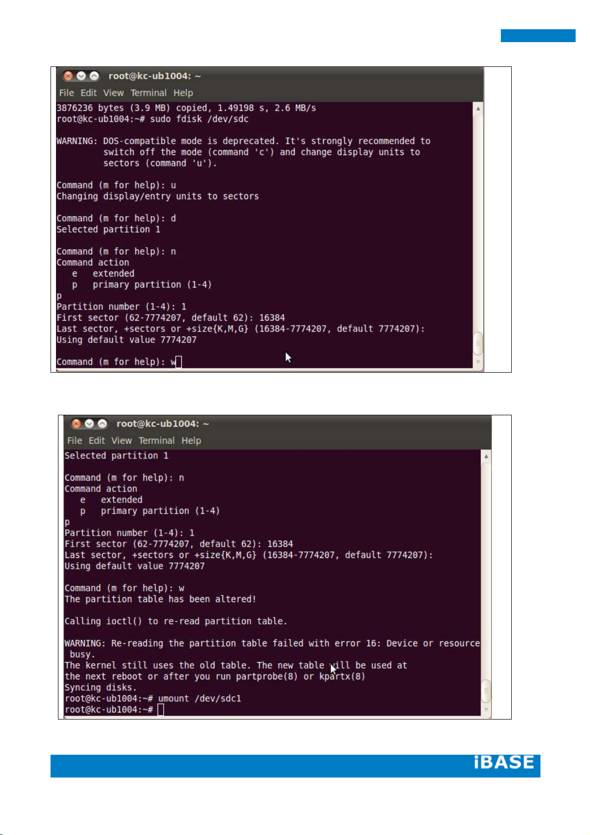
36
SMARC Evaluation Kit
sudo umount /dev/sdb1
Page 63

Copyright © 2013 IBASE Technology Inc. All Rights Reserved.
37
IBASE Technology Inc.
sudo mkfs.ext4 /dev/sdb1
Copy the target file system to SD card partition by extracting rootfs package to
mounted directory:
(assume compressed root file system is F600_linux_fs.tgz)
mkdir /tmp/SD
Page 64

38
SMARC Evaluation Kit
sudo mount /dev/sdb1 /tmp/SD
cd /tmp/SD
Page 65

Copyright © 2013 IBASE Technology Inc. All Rights Reserved.
39
IBASE Technology Inc.
tar xvf ~/linux_bsp/F600_linux_fs.tgz
Copying the file system takes several minutes. The file system content is now on the media.
Page 66

40
SMARC Evaluation Kit
5.1.7. Booting with your SD card
Put SD card in your board and adjust DIP switch to boot from SD. Connect a debug cable to debug port
with serial port 115200/N/8/1 setting on your PC’s serial port program such hyperterminal/teraterm.
Connect a 1080p HDMI monitor to hdmi port. Power on and you will see u-boot prompt.
At u-boot prompt, press Enter before time out. Type the following setting to boot from SD card +
HDMI:
setenv bootcmd_mmc 'run bootargs_base bootargs_mmc; mmc dev 1; mmc read ${loadaddr} 0x800
0x2000; bootm'
setenv bootargs_mmc 'setenv bootargs ${bootargs} root=/dev/mmcblk1p1 rootwait ldo_active=on rw
video=mxcfb0:dev=hdmi,1920x1080M@60,if=RGB24 fbmem=28M rootfstype=ext4'
saveenv
After that, prepare your HDMI LCD, power off and power on again.
You can see Ubuntu Linux is running on hdmi monitor.
Page 67

Copyright © 2013 IBASE Technology Inc. All Rights Reserved.
41
IBASE Technology Inc.
Reading / writing i2c
i2cget.c
/*
i2cget.c - A user-space program to read an I2C register.
Copyright (C) 2005-2012 Jean Delvare <jdelvare@suse.de>
Based on i2cset.c:
Copyright (C) 2001-2003 Frodo Looijaard <frodol@dds.nl>, and
Mark D. Studebaker <mdsxyz123@yahoo.com>
Copyright (C) 2004-2005 Jean Delvare
This program is free software; you can redistribute it and/or modify
it under the terms of the GNU General Public License as published by
the Free Software Foundation; either version 2 of the License, or
(at your option) any later version.
This program is distributed in the hope that it will be useful,
but WITHOUT ANY WARRANTY; without even the implied warranty of
MERCHANTABILITY or FITNESS FOR A PARTICULAR PURPOSE. See the
GNU General Public License for more details.
You should have received a copy of the GNU General Public License
along with this program; if not, write to the Free Software
Foundation, Inc., 51 Franklin Street, Fifth Floor, Boston,
MA 02110-1301 USA.
*/
#include <sys/ioctl.h>
#include <errno.h>
#include <string.h>
#include <stdio.h>
#include <stdlib.h>
#include <unistd.h>
#include <linux/i2c-dev.h>
#include "i2cbusses.h"
#include "util.h"
#include "../version.h"
static void help(void) __attribute__ ((noreturn));
static void help(void)
{
fprintf(stderr,
"Usage: i2cget [-f] [-y] I2CBUS CHIP-ADDRESS [DATA-ADDRESS [MODE]]\n"
" I2CBUS is an integer or an I2C bus name\n"
" ADDRESS is an integer (0x03 - 0x77)\n"
" MODE is one of:\n"
" b (read byte data, default)\n"
" w (read word data)\n"
" c (write byte/read byte)\n"
" Append p for SMBus PEC\n");
exit(1);
}
static int check_funcs(int file, int size, int daddress, int pec)
{
unsigned long funcs;
/* check adapter functionality */
if (ioctl(file, I2C_FUNCS, &funcs) < 0) {
fprintf(stderr, "Error: Could not get the adapter "
"functionality matrix: %s\n", strerror(errno));
6. Appendix A– I2C, GPIO, watchdog reference code Coding.
6.1. How to use I2C in Linux
Page 68

42
SMARC Evaluation Kit
return -1;
}
switch (size) {
case I2C_SMBUS_BYTE:
if (!(funcs & I2C_FUNC_SMBUS_READ_BYTE)) {
fprintf(stderr, MISSING_FUNC_FMT, "SMBus receive byte");
return -1;
}
if (daddress >= 0
&& !(funcs & I2C_FUNC_SMBUS_WRITE_BYTE)) {
fprintf(stderr, MISSING_FUNC_FMT, "SMBus send byte");
return -1;
}
break;
case I2C_SMBUS_BYTE_DATA:
if (!(funcs & I2C_FUNC_SMBUS_READ_BYTE_DATA)) {
fprintf(stderr, MISSING_FUNC_FMT, "SMBus read byte");
return -1;
}
break;
case I2C_SMBUS_WORD_DATA:
if (!(funcs & I2C_FUNC_SMBUS_READ_WORD_DATA)) {
fprintf(stderr, MISSING_FUNC_FMT, "SMBus read word");
return -1;
}
break;
}
if (pec
&& !(funcs & (I2C_FUNC_SMBUS_PEC | I2C_FUNC_I2C))) {
fprintf(stderr, "Warning: Adapter does "
"not seem to support PEC\n");
}
return 0;
}
static int confirm(const char *filename, int address, int size, int daddress,
int pec)
{
int dont = 0;
fprintf(stderr, "WARNING! This program can confuse your I2C "
"bus, cause data loss and worse!\n");
/* Don't let the user break his/her EEPROMs */
if (address >= 0x50 && address <= 0x57 && pec) {
fprintf(stderr, "STOP! EEPROMs are I2C devices, not "
"SMBus devices. Using PEC\non I2C devices may "
"result in unexpected results, such as\n"
"trashing the contents of EEPROMs. We can't "
"let you do that, sorry.\n");
return 0;
}
if (size == I2C_SMBUS_BYTE && daddress >= 0 && pec) {
fprintf(stderr, "WARNING! All I2C chips and some SMBus chips "
"will interpret a write\nbyte command with PEC as a"
"write byte data command, effectively writing a\n"
"value into a register!\n");
dont++;
}
fprintf(stderr, "I will read from device file %s, chip "
"address 0x%02x, ", filename, address);
if (daddress < 0)
fprintf(stderr, "current data\naddress");
else
Page 69

Copyright © 2013 IBASE Technology Inc. All Rights Reserved.
43
IBASE Technology Inc.
fprintf(stderr, "data address\n0x%02x", daddress);
fprintf(stderr, ", using %s.\n",
size == I2C_SMBUS_BYTE ? (daddress < 0 ?
"read byte" : "write byte/read byte") :
size == I2C_SMBUS_BYTE_DATA ? "read byte data" :
"read word data");
if (pec)
fprintf(stderr, "PEC checking enabled.\n");
fprintf(stderr, "Continue? [%s] ", dont ? "y/N" : "Y/n");
fflush(stderr);
if (!user_ack(!dont)) {
fprintf(stderr, "Aborting on user request.\n");
return 0;
}
return 1;
}
int main(int argc, char *argv[])
{
char *end;
int res, i2cbus, address, size, file;
int daddress;
char filename[20];
int pec = 0;
int flags = 0;
int force = 0, yes = 0, version = 0;
/* handle (optional) flags first */
while (1+flags < argc && argv[1+flags][0] == '-') {
switch (argv[1+flags][1]) {
case 'V': version = 1; break;
case 'f': force = 1; break;
case 'y': yes = 1; break;
default:
fprintf(stderr, "Error: Unsupported option "
"\"%s\"!\n", argv[1+flags]);
help();
exit(1);
}
flags++;
}
if (version) {
fprintf(stderr, "i2cget version %s\n", VERSION);
exit(0);
}
if (argc < flags + 3)
help();
i2cbus = lookup_i2c_bus(argv[flags+1]);
if (i2cbus < 0)
help();
address = parse_i2c_address(argv[flags+2]);
if (address < 0)
help();
if (argc > flags + 3) {
size = I2C_SMBUS_BYTE_DATA;
daddress = strtol(argv[flags+3], &end, 0);
if (*end || daddress < 0 || daddress > 0xff) {
fprintf(stderr, "Error: Data address invalid!\n");
help();
}
} else {
size = I2C_SMBUS_BYTE;
daddress = -1;
}
Page 70

44
SMARC Evaluation Kit
if (argc > flags + 4) {
switch (argv[flags+4][0]) {
case 'b': size = I2C_SMBUS_BYTE_DATA; break;
case 'w': size = I2C_SMBUS_WORD_DATA; break;
case 'c': size = I2C_SMBUS_BYTE; break;
default:
fprintf(stderr, "Error: Invalid mode!\n");
help();
}
pec = argv[flags+4][1] == 'p';
}
file = open_i2c_dev(i2cbus, filename, sizeof(filename), 0);
if (file < 0
|| check_funcs(file, size, daddress, pec)
|| set_slave_addr(file, address, force))
exit(1);
if (!yes && !confirm(filename, address, size, daddress, pec))
exit(0);
if (pec && ioctl(file, I2C_PEC, 1) < 0) {
fprintf(stderr, "Error: Could not set PEC: %s\n",
strerror(errno));
close(file);
exit(1);
}
switch (size) {
case I2C_SMBUS_BYTE:
if (daddress >= 0) {
res = i2c_smbus_write_byte(file, daddress);
if (res < 0)
fprintf(stderr, "Warning - write failed\n");
}
res = i2c_smbus_read_byte(file);
break;
case I2C_SMBUS_WORD_DATA:
res = i2c_smbus_read_word_data(file, daddress);
break;
default: /* I2C_SMBUS_BYTE_DATA */
res = i2c_smbus_read_byte_data(file, daddress);
}
close(file);
if (res < 0) {
fprintf(stderr, "Error: Read failed\n");
exit(2);
}
printf("0x%0*x\n", size == I2C_SMBUS_WORD_DATA ? 4 : 2, res);
exit(0);
}
i2cset.c
/*
i2cset.c - A user-space program to write an I2C register.
Copyright (C) 2001-2003 Frodo Looijaard <frodol@dds.nl>, and
Mark D. Studebaker <mdsxyz123@yahoo.com>
Copyright (C) 2004-2012 Jean Delvare <jdelvare@suse.de>
This program is free software; you can redistribute it and/or modify
it under the terms of the GNU General Public License as published by
the Free Software Foundation; either version 2 of the License, or
(at your option) any later version.
This program is distributed in the hope that it will be useful,
but WITHOUT ANY WARRANTY; without even the implied warranty of
MERCHANTABILITY or FITNESS FOR A PARTICULAR PURPOSE. See the
Page 71

Copyright © 2013 IBASE Technology Inc. All Rights Reserved.
45
IBASE Technology Inc.
GNU General Public License for more details.
You should have received a copy of the GNU General Public License
along with this program; if not, write to the Free Software
Foundation, Inc., 51 Franklin Street, Fifth Floor, Boston,
MA 02110-1301 USA.
*/
#include <sys/ioctl.h>
#include <errno.h>
#include <string.h>
#include <stdio.h>
#include <stdlib.h>
#include <unistd.h>
#include <linux/i2c-dev.h>
#include "i2cbusses.h"
#include "util.h"
#include "../version.h"
static void help(void) __attribute__ ((noreturn));
static void help(void)
{
fprintf(stderr,
"Usage: i2cset [-f] [-y] [-m MASK] [-r] I2CBUS CHIP-ADDRESS DATA-ADDRESS [VALUE] ... [MODE]\n"
" I2CBUS is an integer or an I2C bus name\n"
" ADDRESS is an integer (0x03 - 0x77)\n"
" MODE is one of:\n"
" c (byte, no value)\n"
" b (byte data, default)\n"
" w (word data)\n"
" i (I2C block data)\n"
" s (SMBus block data)\n"
" Append p for SMBus PEC\n");
exit(1);
}
static int check_funcs(int file, int size, int pec)
{
unsigned long funcs;
/* check adapter functionality */
if (ioctl(file, I2C_FUNCS, &funcs) < 0) {
fprintf(stderr, "Error: Could not get the adapter "
"functionality matrix: %s\n", strerror(errno));
return -1;
}
switch (size) {
case I2C_SMBUS_BYTE:
if (!(funcs & I2C_FUNC_SMBUS_WRITE_BYTE)) {
fprintf(stderr, MISSING_FUNC_FMT, "SMBus send byte");
return -1;
}
break;
case I2C_SMBUS_BYTE_DATA:
if (!(funcs & I2C_FUNC_SMBUS_WRITE_BYTE_DATA)) {
fprintf(stderr, MISSING_FUNC_FMT, "SMBus write byte");
return -1;
}
break;
case I2C_SMBUS_WORD_DATA:
if (!(funcs & I2C_FUNC_SMBUS_WRITE_WORD_DATA)) {
fprintf(stderr, MISSING_FUNC_FMT, "SMBus write word");
return -1;
}
break;
case I2C_SMBUS_BLOCK_DATA:
Page 72

46
SMARC Evaluation Kit
if (!(funcs & I2C_FUNC_SMBUS_WRITE_BLOCK_DATA)) {
fprintf(stderr, MISSING_FUNC_FMT, "SMBus block write");
return -1;
}
break;
case I2C_SMBUS_I2C_BLOCK_DATA:
if (!(funcs & I2C_FUNC_SMBUS_WRITE_I2C_BLOCK)) {
fprintf(stderr, MISSING_FUNC_FMT, "I2C block write");
return -1;
}
break;
}
if (pec
&& !(funcs & (I2C_FUNC_SMBUS_PEC | I2C_FUNC_I2C))) {
fprintf(stderr, "Warning: Adapter does "
"not seem to support PEC\n");
}
return 0;
}
static int confirm(const char *filename, int address, int size, int daddress,
int value, int vmask, const unsigned char *block, int len,
int pec)
{
int dont = 0;
fprintf(stderr, "WARNING! This program can confuse your I2C "
"bus, cause data loss and worse!\n");
if (address >= 0x50 && address <= 0x57) {
fprintf(stderr, "DANGEROUS! Writing to a serial "
"EEPROM on a memory DIMM\nmay render your "
"memory USELESS and make your system "
"UNBOOTABLE!\n");
dont++;
}
fprintf(stderr, "I will write to device file %s, chip address "
"0x%02x, data address\n0x%02x, ", filename, address, daddress);
if (size == I2C_SMBUS_BYTE)
fprintf(stderr, "no data.\n");
else if (size == I2C_SMBUS_BLOCK_DATA ||
size == I2C_SMBUS_I2C_BLOCK_DATA) {
int i;
fprintf(stderr, "data");
for (i = 0; i < len; i++)
fprintf(stderr, " 0x%02x", block[i]);
fprintf(stderr, ", mode %s.\n", size == I2C_SMBUS_BLOCK_DATA
? "smbus block" : "i2c block");
} else
fprintf(stderr, "data 0x%02x%s, mode %s.\n", value,
vmask ? " (masked)" : "",
size == I2C_SMBUS_BYTE_DATA ? "byte" : "word");
if (pec)
fprintf(stderr, "PEC checking enabled.\n");
fprintf(stderr, "Continue? [%s] ", dont ? "y/N" : "Y/n");
fflush(stderr);
if (!user_ack(!dont)) {
fprintf(stderr, "Aborting on user request.\n");
return 0;
}
return 1;
}
int main(int argc, char *argv[])
{
Page 73

Copyright © 2013 IBASE Technology Inc. All Rights Reserved.
47
IBASE Technology Inc.
char *end;
const char *maskp = NULL;
int res, i2cbus, address, size, file;
int value, daddress, vmask = 0;
char filename[20];
int pec = 0;
int flags = 0;
int force = 0, yes = 0, version = 0, readback = 0;
unsigned char block[I2C_SMBUS_BLOCK_MAX];
int len;
/* handle (optional) flags first */
while (1+flags < argc && argv[1+flags][0] == '-') {
switch (argv[1+flags][1]) {
case 'V': version = 1; break;
case 'f': force = 1; break;
case 'y': yes = 1; break;
case 'm':
if (2+flags < argc)
maskp = argv[2+flags];
flags++;
break;
case 'r': readback = 1; break;
default:
fprintf(stderr, "Error: Unsupported option "
"\"%s\"!\n", argv[1+flags]);
help();
exit(1);
}
flags++;
}
if (version) {
fprintf(stderr, "i2cset version %s\n", VERSION);
exit(0);
}
if (argc < flags + 4)
help();
i2cbus = lookup_i2c_bus(argv[flags+1]);
if (i2cbus < 0)
help();
address = parse_i2c_address(argv[flags+2]);
if (address < 0)
help();
daddress = strtol(argv[flags+3], &end, 0);
if (*end || daddress < 0 || daddress > 0xff) {
fprintf(stderr, "Error: Data address invalid!\n");
help();
}
/* check for command/mode */
if (argc == flags + 4) {
/* Implicit "c" */
size = I2C_SMBUS_BYTE;
} else if (argc == flags + 5) {
/* "c", "cp", or implicit "b" */
if (!strcmp(argv[flags+4], "c")
|| !strcmp(argv[flags+4], "cp")) {
size = I2C_SMBUS_BYTE;
pec = argv[flags+4][1] == 'p';
} else {
size = I2C_SMBUS_BYTE_DATA;
}
} else {
/* All other commands */
if (strlen(argv[argc-1]) > 2
|| (strlen(argv[argc-1]) == 2 && argv[argc-1][1] != 'p')) {
Page 74

48
SMARC Evaluation Kit
fprintf(stderr, "Error: Invalid mode '%s'!\n", argv[argc-1]);
help();
}
switch (argv[argc-1][0]) {
case 'b': size = I2C_SMBUS_BYTE_DATA; break;
case 'w': size = I2C_SMBUS_WORD_DATA; break;
case 's': size = I2C_SMBUS_BLOCK_DATA; break;
case 'i': size = I2C_SMBUS_I2C_BLOCK_DATA; break;
default:
fprintf(stderr, "Error: Invalid mode '%s'!\n", argv[argc-1]);
help();
}
pec = argv[argc-1][1] == 'p';
if (size == I2C_SMBUS_BLOCK_DATA || size == I2C_SMBUS_I2C_BLOCK_DATA) {
if (pec && size == I2C_SMBUS_I2C_BLOCK_DATA) {
fprintf(stderr, "Error: PEC not supported for I2C block writes!\n");
help();
}
if (maskp) {
fprintf(stderr, "Error: Mask not supported for block writes!\n");
help();
}
if (argc > (int)sizeof(block) + flags + 5) {
fprintf(stderr, "Error: Too many arguments!\n");
help();
}
} else if (argc != flags + 6) {
fprintf(stderr, "Error: Too many arguments!\n");
help();
}
}
len = 0; /* Must always initialize len since it is passed to confirm() */
/* read values from command line */
switch (size) {
case I2C_SMBUS_BYTE_DATA:
case I2C_SMBUS_WORD_DATA:
value = strtol(argv[flags+4], &end, 0);
if (*end || value < 0) {
fprintf(stderr, "Error: Data value invalid!\n");
help();
}
if ((size == I2C_SMBUS_BYTE_DATA && value > 0xff)
|| (size == I2C_SMBUS_WORD_DATA && value > 0xffff)) {
fprintf(stderr, "Error: Data value out of range!\n");
help();
}
break;
case I2C_SMBUS_BLOCK_DATA:
case I2C_SMBUS_I2C_BLOCK_DATA:
for (len = 0; len + flags + 5 < argc; len++) {
value = strtol(argv[flags + len + 4], &end, 0);
if (*end || value < 0) {
fprintf(stderr, "Error: Data value invalid!\n");
help();
}
if (value > 0xff) {
fprintf(stderr, "Error: Data value out of range!\n");
help();
}
block[len] = value;
}
value = -1;
break;
default:
value = -1;
break;
}
if (maskp) {
Page 75

Copyright © 2013 IBASE Technology Inc. All Rights Reserved.
49
IBASE Technology Inc.
vmask = strtol(maskp, &end, 0);
if (*end || vmask == 0) {
fprintf(stderr, "Error: Data value mask invalid!\n");
help();
}
if (((size == I2C_SMBUS_BYTE || size == I2C_SMBUS_BYTE_DATA)
&& vmask > 0xff) || vmask > 0xffff) {
fprintf(stderr, "Error: Data value mask out of range!\n");
help();
}
}
file = open_i2c_dev(i2cbus, filename, sizeof(filename), 0);
if (file < 0
|| check_funcs(file, size, pec)
|| set_slave_addr(file, address, force))
exit(1);
if (!yes && !confirm(filename, address, size, daddress,
value, vmask, block, len, pec))
exit(0);
if (vmask) {
int oldvalue;
switch (size) {
case I2C_SMBUS_BYTE:
oldvalue = i2c_smbus_read_byte(file);
break;
case I2C_SMBUS_WORD_DATA:
oldvalue = i2c_smbus_read_word_data(file, daddress);
break;
default:
oldvalue = i2c_smbus_read_byte_data(file, daddress);
}
if (oldvalue < 0) {
fprintf(stderr, "Error: Failed to read old value\n");
exit(1);
}
value = (value & vmask) | (oldvalue & ~vmask);
if (!yes) {
fprintf(stderr, "Old value 0x%0*x, write mask "
"0x%0*x: Will write 0x%0*x to register "
"0x%02x\n",
size == I2C_SMBUS_WORD_DATA ? 4 : 2, oldvalue,
size == I2C_SMBUS_WORD_DATA ? 4 : 2, vmask,
size == I2C_SMBUS_WORD_DATA ? 4 : 2, value,
daddress);
fprintf(stderr, "Continue? [Y/n] ");
fflush(stderr);
if (!user_ack(1)) {
fprintf(stderr, "Aborting on user request.\n");
exit(0);
}
}
}
if (pec && ioctl(file, I2C_PEC, 1) < 0) {
fprintf(stderr, "Error: Could not set PEC: %s\n",
strerror(errno));
close(file);
exit(1);
}
switch (size) {
case I2C_SMBUS_BYTE:
res = i2c_smbus_write_byte(file, daddress);
Page 76

50
SMARC Evaluation Kit
break;
case I2C_SMBUS_WORD_DATA:
res = i2c_smbus_write_word_data(file, daddress, value);
break;
case I2C_SMBUS_BLOCK_DATA:
res = i2c_smbus_write_block_data(file, daddress, len, block);
break;
case I2C_SMBUS_I2C_BLOCK_DATA:
res = i2c_smbus_write_i2c_block_data(file, daddress, len, block);
break;
default: /* I2C_SMBUS_BYTE_DATA */
res = i2c_smbus_write_byte_data(file, daddress, value);
break;
}
if (res < 0) {
fprintf(stderr, "Error: Write failed\n");
close(file);
exit(1);
}
if (pec) {
if (ioctl(file, I2C_PEC, 0) < 0) {
fprintf(stderr, "Error: Could not clear PEC: %s\n",
strerror(errno));
close(file);
exit(1);
}
}
if (!readback) { /* We're done */
close(file);
exit(0);
}
switch (size) {
case I2C_SMBUS_BYTE:
res = i2c_smbus_read_byte(file);
value = daddress;
break;
case I2C_SMBUS_WORD_DATA:
res = i2c_smbus_read_word_data(file, daddress);
break;
default: /* I2C_SMBUS_BYTE_DATA */
res = i2c_smbus_read_byte_data(file, daddress);
}
close(file);
if (res < 0) {
printf("Warning - readback failed\n");
} else
if (res != value) {
printf("Warning - data mismatch - wrote "
"0x%0*x, read back 0x%0*x\n",
size == I2C_SMBUS_WORD_DATA ? 4 : 2, value,
size == I2C_SMBUS_WORD_DATA ? 4 : 2, res);
} else {
printf("Value 0x%0*x written, readback matched\n",
size == I2C_SMBUS_WORD_DATA ? 4 : 2, value);
}
exit(0);
}
Utils/headers
/*
i2cbusses: Print the installed i2c busses for both 2.4 and 2.6 kernels.
Part of user-space programs to access for I2C
devices.
*/
/* For strdup and snprintf */
Page 77

Copyright © 2013 IBASE Technology Inc. All Rights Reserved.
51
IBASE Technology Inc.
#define _BSD_SOURCE 1
#include <sys/types.h>
#include <sys/stat.h>
#include <sys/param.h> /* for NAME_MAX */
#include <sys/ioctl.h>
#include <string.h>
#include <strings.h> /* for strcasecmp() */
#include <stdio.h>
#include <stdlib.h>
#include <unistd.h>
#include <limits.h>
#include <dirent.h>
#include <fcntl.h>
#include <errno.h>
#include "i2cbusses.h"
#include <linux/i2c-dev.h>
enum adt { adt_dummy, adt_isa, adt_i2c, adt_smbus, adt_unknown };
struct adap_type {
const char *funcs;
const char* algo;
};
static struct adap_type adap_types[5] = {
{ .funcs = "dummy",
.algo = "Dummy bus", },
{ .funcs = "isa",
.algo = "ISA bus", },
{ .funcs = "i2c",
.algo = "I2C adapter", },
{ .funcs = "smbus",
.algo = "SMBus adapter", },
{ .funcs = "unknown",
.algo = "N/A", },
};
static enum adt i2c_get_funcs(int i2cbus)
{
unsigned long funcs;
int file;
char filename[20];
enum adt ret;
file = open_i2c_dev(i2cbus, filename, sizeof(filename), 1);
if (file < 0)
return adt_unknown;
if (ioctl(file, I2C_FUNCS, &funcs) < 0)
ret = adt_unknown;
else if (funcs & I2C_FUNC_I2C)
ret = adt_i2c;
else if (funcs & (I2C_FUNC_SMBUS_BYTE |
I2C_FUNC_SMBUS_BYTE_DATA |
I2C_FUNC_SMBUS_WORD_DATA))
ret = adt_smbus;
else
ret = adt_dummy;
close(file);
return ret;
}
/* Remove trailing spaces from a string
Return the new string length including the trailing NUL */
static int rtrim(char *s)
{
int i;
for (i = strlen(s) - 1; i >= 0 && (s[i] == ' ' || s[i] == '\n'); i--)
Page 78

52
SMARC Evaluation Kit
s[i] = '\0';
return i + 2;
}
void free_adapters(struct i2c_adap *adapters)
{
int i;
for (i = 0; adapters[i].name; i++)
free(adapters[i].name);
free(adapters);
}
/* We allocate space for the adapters in bunches. The last item is a
terminator, so here we start with room for 7 adapters, which should
be enough in most cases. If not, we allocate more later as needed. */
#define BUNCH 8
/* n must match the size of adapters at calling time */
static struct i2c_adap *more_adapters(struct i2c_adap *adapters, int n)
{
struct i2c_adap *new_adapters;
new_adapters = realloc(adapters, (n + BUNCH) * sizeof(struct i2c_adap));
if (!new_adapters) {
free_adapters(adapters);
return NULL;
}
memset(new_adapters + n, 0, BUNCH * sizeof(struct i2c_adap));
return new_adapters;
}
struct i2c_adap *gather_i2c_busses(void)
{
char s[120];
struct dirent *de, *dde;
DIR *dir, *ddir;
FILE *f;
char fstype[NAME_MAX], sysfs[NAME_MAX], n[NAME_MAX];
int foundsysfs = 0;
int count=0;
struct i2c_adap *adapters;
adapters = calloc(BUNCH, sizeof(struct i2c_adap));
if (!adapters)
return NULL;
/* look in /proc/bus/i2c */
if ((f = fopen("/proc/bus/i2c", "r"))) {
while (fgets(s, 120, f)) {
char *algo, *name, *type, *all;
int len_algo, len_name, len_type;
int i2cbus;
algo = strrchr(s, '\t');
*(algo++) = '\0';
len_algo = rtrim(algo);
name = strrchr(s, '\t');
*(name++) = '\0';
len_name = rtrim(name);
type = strrchr(s, '\t');
*(type++) = '\0';
len_type = rtrim(type);
sscanf(s, "i2c-%d", &i2cbus);
if ((count + 1) % BUNCH == 0) {
/* We need more space */
Page 79

Copyright © 2013 IBASE Technology Inc. All Rights Reserved.
53
IBASE Technology Inc.
adapters = more_adapters(adapters, count + 1);
if (!adapters)
return NULL;
}
all = malloc(len_name + len_type + len_algo);
if (all == NULL) {
free_adapters(adapters);
return NULL;
}
adapters[count].nr = i2cbus;
adapters[count].name = strcpy(all, name);
adapters[count].funcs = strcpy(all + len_name, type);
adapters[count].algo = strcpy(all + len_name + len_type,
algo);
count++;
}
fclose(f);
goto done;
}
/* look in sysfs */
/* First figure out where sysfs was mounted */
if ((f = fopen("/proc/mounts", "r")) == NULL) {
goto done;
}
while (fgets(n, NAME_MAX, f)) {
sscanf(n, "%*[^ ] %[^ ] %[^ ] %*s\n", sysfs, fstype);
if (strcasecmp(fstype, "sysfs") == 0) {
foundsysfs++;
break;
}
}
fclose(f);
if (! foundsysfs) {
goto done;
}
/* Bus numbers in i2c-adapter don't necessarily match those in
i2c-dev and what we really care about are the i2c-dev numbers.
Unfortunately the names are harder to get in i2c-dev */
strcat(sysfs, "/class/i2c-dev");
if(!(dir = opendir(sysfs)))
goto done;
/* go through the busses */
while ((de = readdir(dir)) != NULL) {
if (!strcmp(de->d_name, "."))
continue;
if (!strcmp(de->d_name, ".."))
continue;
/* this should work for kernels 2.6.5 or higher and */
/* is preferred because is unambiguous */
sprintf(n, "%s/%s/name", sysfs, de->d_name);
f = fopen(n, "r");
/* this seems to work for ISA */
if(f == NULL) {
sprintf(n, "%s/%s/device/name", sysfs, de->d_name);
f = fopen(n, "r");
}
/* non-ISA is much harder */
/* and this won't find the correct bus name if a driver
has more than one bus */
if(f == NULL) {
sprintf(n, "%s/%s/device", sysfs, de->d_name);
if(!(ddir = opendir(n)))
continue;
while ((dde = readdir(ddir)) != NULL) {
if (!strcmp(dde->d_name, "."))
continue;
if (!strcmp(dde->d_name, ".."))
Page 80

54
SMARC Evaluation Kit
continue;
if ((!strncmp(dde->d_name, "i2c-", 4))) {
sprintf(n, "%s/%s/device/%s/name",
sysfs, de->d_name, dde->d_name);
if((f = fopen(n, "r")))
goto found;
}
}
}
found:
if (f != NULL) {
int i2cbus;
enum adt type;
char *px;
px = fgets(s, 120, f);
fclose(f);
if (!px) {
fprintf(stderr, "%s: read error\n", n);
continue;
}
if ((px = strchr(s, '\n')) != NULL)
*px = 0;
if (!sscanf(de->d_name, "i2c-%d", &i2cbus))
continue;
if (!strncmp(s, "ISA ", 4)) {
type = adt_isa;
} else {
/* Attempt to probe for adapter capabilities */
type = i2c_get_funcs(i2cbus);
}
if ((count + 1) % BUNCH == 0) {
/* We need more space */
adapters = more_adapters(adapters, count + 1);
if (!adapters)
return NULL;
}
adapters[count].nr = i2cbus;
adapters[count].name = strdup(s);
if (adapters[count].name == NULL) {
free_adapters(adapters);
return NULL;
}
adapters[count].funcs = adap_types[type].funcs;
adapters[count].algo = adap_types[type].algo;
count++;
}
}
closedir(dir);
done:
return adapters;
}
static int lookup_i2c_bus_by_name(const char *bus_name)
{
struct i2c_adap *adapters;
int i, i2cbus = -1;
adapters = gather_i2c_busses();
if (adapters == NULL) {
fprintf(stderr, "Error: Out of memory!\n");
return -3;
}
/* Walk the list of i2c busses, looking for the one with the
right name */
for (i = 0; adapters[i].name; i++) {
Page 81

Copyright © 2013 IBASE Technology Inc. All Rights Reserved.
55
IBASE Technology Inc.
if (strcmp(adapters[i].name, bus_name) == 0) {
if (i2cbus >= 0) {
fprintf(stderr,
"Error: I2C bus name is not unique!\n");
i2cbus = -4;
goto done;
}
i2cbus = adapters[i].nr;
}
}
if (i2cbus == -1)
fprintf(stderr, "Error: I2C bus name doesn't match any "
"bus present!\n");
done:
free_adapters(adapters);
return i2cbus;
}
/*
* Parse an I2CBUS command line argument and return the corresponding
* bus number, or a negative value if the bus is invalid.
*/
int lookup_i2c_bus(const char *i2cbus_arg)
{
unsigned long i2cbus;
char *end;
i2cbus = strtoul(i2cbus_arg, &end, 0);
if (*end || !*i2cbus_arg) {
/* Not a number, maybe a name? */
return lookup_i2c_bus_by_name(i2cbus_arg);
}
if (i2cbus > 0xFFFFF) {
fprintf(stderr, "Error: I2C bus out of range!\n");
return -2;
}
return i2cbus;
}
/*
* Parse a CHIP-ADDRESS command line argument and return the corresponding
* chip address, or a negative value if the address is invalid.
*/
int parse_i2c_address(const char *address_arg)
{
long address;
char *end;
address = strtol(address_arg, &end, 0);
if (*end || !*address_arg) {
fprintf(stderr, "Error: Chip address is not a number!\n");
return -1;
}
if (address < 0x03 || address > 0x77) {
fprintf(stderr, "Error: Chip address out of range "
"(0x03-0x77)!\n");
return -2;
}
return address;
}
int open_i2c_dev(int i2cbus, char *filename, size_t size, int quiet)
{
int file;
snprintf(filename, size, "/dev/i2c/%d", i2cbus);
filename[size - 1] = '\0';
Page 82

56
SMARC Evaluation Kit
file = open(filename, O_RDWR);
if (file < 0 && (errno == ENOENT || errno == ENOTDIR)) {
sprintf(filename, "/dev/i2c-%d", i2cbus);
file = open(filename, O_RDWR);
}
if (file < 0 && !quiet) {
if (errno == ENOENT) {
fprintf(stderr, "Error: Could not open file "
"`/dev/i2c-%d' or `/dev/i2c/%d': %s\n",
i2cbus, i2cbus, strerror(ENOENT));
} else {
fprintf(stderr, "Error: Could not open file "
"`%s': %s\n", filename, strerror(errno));
if (errno == EACCES)
fprintf(stderr, "Run as root?\n");
}
}
return file;
}
int set_slave_addr(int file, int address, int force)
{
/* With force, let the user read from/write to the registers
even when a driver is also running */
if (ioctl(file, force ? I2C_SLAVE_FORCE : I2C_SLAVE, address) < 0) {
fprintf(stderr,
"Error: Could not set address to 0x%02x: %s\n",
address, strerror(errno));
return -errno;
}
return 0;
}
/*
i2cbusses.h
*/
#ifndef _I2CBUSSES_H
#define _I2CBUSSES_H
#include <unistd.h>
struct i2c_adap {
int nr;
char *name;
const char *funcs;
const char *algo;
};
struct i2c_adap *gather_i2c_busses(void);
void free_adapters(struct i2c_adap *adapters);
int lookup_i2c_bus(const char *i2cbus_arg);
int parse_i2c_address(const char *address_arg);
int open_i2c_dev(int i2cbus, char *filename, size_t size, int quiet);
int set_slave_addr(int file, int address, int force);
#define MISSING_FUNC_FMT "Error: Adapter does not have %s capability\n"
#endif
/*
util.c - helper functions
*/
#include <stdio.h>
#include "util.h"
Page 83

Copyright © 2013 IBASE Technology Inc. All Rights Reserved.
57
IBASE Technology Inc.
/* Return 1 if we should continue, 0 if we should abort */
int user_ack(int def)
{
char s[2];
int ret;
if (!fgets(s, 2, stdin))
return 0; /* Nack by default */
switch (s[0]) {
case 'y':
case 'Y':
ret = 1;
break;
case 'n':
case 'N':
ret = 0;
break;
default:
ret = def;
}
/* Flush extra characters */
while (s[0] != '\n') {
int c = fgetc(stdin);
if (c == EOF) {
ret = 0;
break;
}
s[0] = c;
}
return ret;
}
/*
util - helper functions
*/
#ifndef _UTIL_H
#define _UTIL_H
extern int user_ack(int def);
#endif /* _UTIL_H */
Version.h
#define VERSION "3.1.1"
Page 84

58
SMARC Evaluation Kit
RM-F600
Logical Number
Physical Number
1
32 3 34 5 36
7
38 8 39
# GPIO example 1: Output (take GPIO 32 as example)
echo 32 > /sys/class/gpio/export
echo out > /sys/class/gpio/gpio32/direction
echo 0 > /sys/class/gpio/gpio32/value
echo 1 > /sys/class/gpio/gpio32/value
# GPIO example 2: Input (take GPIO 32 as example)
echo 32 > /sys/class/gpio/export
echo in > /sys/class/gpio/gpio32/direction
cat /sys/class/gpio/gpio32/value
6.2. How to use GPIO in Linux
6.2.1. GPIO mapping table
6.2.2. GPIO sample code
Page 85

Copyright © 2013 IBASE Technology Inc. All Rights Reserved.
59
IBASE Technology Inc.
#include <stdio.h>
#include <stdlib.h>
#include <unistd.h>
#include <fcntl.h>
int main(void)
{
int fd = open("/dev/watchdog", O_WRONLY);
int ret = 0;
if (fd == -1) {
perror("watchdog");
exit(EXIT_FAILURE);
}
while (1) {
ret = write(fd, "\0", 1);
if (ret != 1) {
ret = -1;
break;
}
puts("[WDT] Keep alive");
sleep(50);
}
close(fd);
return ret;
}
6.2.3. How to use Watch dog in Linux
Page 86

60
SMARC Evaluation Kit
Group
Circuit Net
Ball
Mixed Functions
CSPI1 [SPI]
CSPI1_SS1
G21
EIM_D19
CSPI1
CSPI1_SS2
F22
EIM_D24
CSPI1
CSPI1_MOSI
V6
KEY_ROW0
CSPI1
CSPI1_MISO
U7
KEY_COL1
CSPI1
CSPI1_CLK
W5
KEY_COL0
CSPI2 [SPI]
CSPI2_SS0
K20
EIM_RW
CSPI2
CSPI2_SS1
K22
EIM_LBA
CSPI2
CSPI2_MOSI
J23
EIM_CS1
CSPI2
CSPI2_MISO
J24
EIM_OE
CSPI2
CSPI2_CLK
H24
EIM_CS0
Battery
CHARGING#
H19
EIM_A25
Battery
BATLOW#
D25
EIM_D25
Battery
CHARGER_PRSNT#
J20
EIM_D30
Carrier Board
RESET_OUT#
P5
GPIO_19
Carrier Board
Carrier_STBY#
R4
GPIO_5
Carrier Board
Carrier_PWR_ON
R2
GPIO_16
Carrier Board
Carrier_LID#
E23
EIM_D21
Carrier Board
Carrier_SLEEP#
G22
EIM_D25
HDMI
HDMI_DDC_DAT_IN
C25
EIM_D16
HDMI
HDMI_DDC_CLK_IN
E22
EIM_EB2
HDMI
HDMI_HPD
K1
HDMI_HPD
HDMI
HDMI_CEC_IN
K2
HDMI_DDCCEC
HDMI
HDMI_CLKM
J5
HDMI_CLKM
HDMI
HDMI_CLKP
J6
HDMI_CLKP
HDMI
HDMI_D0M
K5
HDMI_D0M
7. Appendix B - i.MX6 CPU ball out Table.
This Chapter is referenced for advanced SW Engineer to modify the Kernel driver or
make their own BSP. Please check Freescale i.MX6 specification, porting guide and user
manuals carefully
Link: http://www.freescale.com/webapp/sps/site/taxonomy.jsp?code=IMX6X_SERIES&cof=0&am=0
Page 87

Copyright © 2013 IBASE Technology Inc. All Rights Reserved.
61
IBASE Technology Inc.
HDMI
HDMI_D0P
K6
HDMI_D0P
HDMI
HDMI_D1M
J3
HDMI_D1M
HDMI
HDMI_D1P
J4
HDMI_D1P
HDMI
HDMI_D2M
K3
HDMI_D2M
HDMI
HDMI_D2P
K4
HDMI_D2P
USB_OTG
USB_OTG_OC#
H20
EIM_D21
USB_OTG
USB_OTG_ID
T4
GPIO_1
USB_OTG
USB_OTG_DN
B6
USB_OTG_DN
USB_OTG
USB_OTG_DP
A6
USB_OTG_DP
**USB
USB1_DP
E10
USB1_DP
USB
USB1_DN
F10
USB1_DN
UART1
UART1_TX
M1
CSI0_DAT10
UART1
UART1_RX
M3
CSI0_DAT11
UART2
UART2_TX
E24
EIM_D26
UART2
UART2_RX
E25
EIM_D27
UART4
UART4_TX
M2
CSI0_DAT12
UART4
UART4_RX
L1
CSI0_DAT13
UART4
UART4_RTS#
L4
CSI0_DAT16
UART4
UART4_CTS#
L3
CSI0_DAT17
UART5
UART5_TX
M4
CSI0_DAT14
UART5
UART5_RX
M5
CSI0_DAT15
UART5
UART5_RTS#
M6
CSI0_DAT18
UART5
UART5_CTS#
L6
CSI0_DAT19
PMIC
PWR_BTN_SNS
J19
EIM_D29
PMIC
PMIC_INT#
P6
GPIO_18
PMIC
MX6_ONOFF
D12
ONOFF
PMIC
POR_B
C11
POR#
PMIC
PMIC_STBY_REQ
F11
PMIC_STBY_REQ
PMIC
PMIC_ON_REQ
D11
PMIC_ON_REQ
GPIO
GPIO_0
E19
SD1_DAT2
GPIO
GPIO_1
H25
EIM_A16
GPIO
GPIO_2
G24
EIM_A17
GPIO
GPIO_3
J22
EIM_A18
GPIO
GPIO_4
G25
EIM_A19
GPIO
GPIO_5
H22
EIM_A20
GPIO
GPIO_6
H23
EIM_A21
Page 88

62
SMARC Evaluation Kit
GPIO
GPIO_7
F24
EIM_A22
GPIO
GPIO_8
J21
EIM_A23
GPIO
GPIO_9
F21
EIM_D17
GPIO
GPIO_10
D24
EIM_D18
GPIO
GPIO_11
G20
EIM_D20
WDT
WDOG#
F18
SD1_DAT3
SD2
SD2_CMD
F19
SD2_CMD
SD2
SD2_CLK
C21
SD2_CLK
SD2
SD2_DATA0
A22
SD2_DATA0
SD2
SD2_DATA1
E20
SD2_DATA1
SD2
SD2_DATA2
A23
SD2_DATA2
SD2
SD2_DATA3
B22
SD2_DATA3
SD2
SD2_CD#
R6
GPIO_4
SD2
SD2_WP
T1
GPIO_2
SD2
SD2_PWR_EN
U6
KEY_ROW1
SD3
SD3_CMD
B13
SD3_CMD
SD3
SD3_CLK
D14
SD3_CLK
SD3
SD3_RST#
D15
SD3_RST
SD3
SD3_DATA0
E14
SD3_DATA0
SD3
SD3_DATA1
F14
SD3_DATA1
SD3
SD3_DATA2
A15
SD3_DATA2
SD3
SD3_DATA3
B15
SD3_DATA3
SD3
SD3_DATA4
D13
SD3_DATA4
SD3
SD3_DATA5
C13
SD3_DATA5
SD3
SD3_DATA6
E13
SD3_DATA6
SD3
SD3_DATA7
F13
SD3_DATA7
eMMC
eMMC_CLK
E16
SD4_CLK
eMMC
eMMC_CMD
B17
SD4_CMD
eMMC
eMMC_RST#
A16
NANDF_ALE
eMMC
eMMC_DATA0
D18
SD4_DAT0
eMMC
eMMC_DATA1
B19
SD4_DAT1
eMMC
eMMC_DATA2
F17
SD4_DAT2
eMMC
eMMC_DATA3
A20
SD4_DAT3
eMMC
eMMC_DATA4
E18
SD4_DAT4
eMMC
eMMC_DATA5
C19
SD4_DAT5
eMMC
eMMC_DATA6
B20
SD4_DAT6
Page 89

Copyright © 2013 IBASE Technology Inc. All Rights Reserved.
63
IBASE Technology Inc.
eMMC
eMMC_DATA7
D19
SD4_DAT7
LCD
LCD_PWR_EN
C16
NANDF_CS1
LCD
LCD_BKLT_EN
A17
NANDF_CS2
LCD
LCD_BKLT_PWM
T2
GPIO_9
LCD
LCD_CLK
N19
DI0_DISP_CLK
LCD
LCD_HSYNC
N25
DI0_PIN2
LCD
LCD_VSYNC
N20
DI0_PIN3
LCD
LCD_DE
N21
DI0_PIN15
LCD
LCD_DAT0
P24
DSP0_DAT0
LCD
LCD_DAT1
P22
DSP0_DAT1
LCD
LCD_DAT2
P23
DSP0_DAT2
LCD
LCD_DAT3
P21
DSP0_DAT3
LCD
LCD_DAT4
P20
DSP0_DAT4
LCD
LCD_DAT5
R25
DSP0_DAT5
LCD
LCD_DAT6
R23
DSP0_DAT6
LCD
LCD_DAT7
R24
DSP0_DAT7
LCD
LCD_DAT8
R22
DSP0_DAT8
LCD
LCD_DAT9
T25
DSP0_DAT9
LCD
LCD_DAT10
R21
DSP0_DAT10
LCD
LCD_DAT11
T23
DSP0_DAT11
LCD
LCD_DAT12
T24
DSP0_DAT12
LCD
LCD_DAT13
R20
DSP0_DAT13
LCD
LCD_DAT14
U25
DSP0_DAT14
LCD
LCD_DAT15
T22
DSP0_DAT15
LCD
LCD_DAT16
T21
DSP0_DAT16
LCD
LCD_DAT17
U24
DSP0_DAT17
LCD
LCD_DAT18
V25
DSP0_DAT18
LCD
LCD_DAT19
U23
DSP0_DAT19
LCD
LCD_DAT20
U22
DSP0_DAT20
LCD
LCD_DAT21
T20
DSP0_DAT21
LCD
LCD_DAT22
V24
DSP0_DAT22
LCD
LCD_DAT23
W24
DSP0_DAT23
LVDS
LVDS0_TX0_N
U2
LVDS0_TX0_N
LVDS
LVDS0_TX0_P
U1
LVDS0_TX0_P
LVDS
LVDS0_TX1_N
U4
LVDS0_TX1_N
LVDS
LVDS0_TX1_P
U3
LVDS0_TX1_P
LVDS
LVDS0_TX2_N
V2
LVDS0_TX2_N
LVDS
LVDS0_TX2_P
V1
LVDS0_TX2_P
Page 90

64
SMARC Evaluation Kit
LVDS
LVDS0_TX3_N
W2
LVDS0_TX3_N
LVDS
LVDS0_TX3_P
W1
LVDS0_TX3_P
LVDS
LVDS0_CLK_N
V4
LVDS0_CLK_N
LVDS
LVDS0_CLK_P
V3
LVDS0_CLK_P
PCIe
PCIE_RST#
R1
GPIO_17
PCIe
PCIE_WAKE#
P3
CSI0_DATA_EN
PCIe
PCIE_CLK1_N
C7
CLK1_N
PCIe
PCIE_CLK1_P
D7
CLK1_P
PCIe
PCIE_RXM
B1
PCIE_RXM
PCIe
PCIE_RXP
B2
PCIE_RXP
PCIe
PCIE_TXM
A3
PCIE_TXM
PCIe
PCIE_TXP
B3
PCIE_TXP
SATA
SATA_RXP
B14
SATA_RXP
SATA
SATA_RXN
A14
SATA_RXM
SATA
SATA_TXN
B12
SATA_TXM
SATA
SATA_TXP
A12
SATA_TXP
I2C1
I2C1_SCL (I2C_PM)
N5
CSI0_DAT9
I2C1
I2C1_SDA (I2C_PM)
N6
CSI0_DAT8
I2C2
I2C2_SCL (I2C_CAM0)
U5
KEY_COL3
I2C2
I2C2_SDA (I2C_CAM0)
T7
KEY_ROW3
I2C3
I2C3_SCL (I2C_LCD)
R7
GPIO_3
I2C3
I2C3_SDA (I2C_LCD)
T3
GPIO_6
I2C4
I2C4_SCL (I2C_GP)
R3
GPIO_7
I2C4
I2C4_SDA (I2C_GP)
R5
GPIO_8
Toouch
Touch_INT#(GPIO_6)
B18
NANDF_D5
I2S
AUD3_TXC
N1
CSI0_DAT4
I2S
AUD3_TXD
P2
CSI0_DAT5
I2S
AUD3_TXFS
N4
CSI0_DAT6
I2S
AUD3_RXD
N3
CSI0_DAT7
I2S
HAD_RST# (GPIO_4)
D17
NANDF_D3
CLOCK
GPIO_0_CLKO
GPIO_0
CAN1
CAN1_TX
W6
KEY_COL2
CAN1
CAN1_RX
W4
KEY_ROW2
Page 91

Copyright © 2013 IBASE Technology Inc. All Rights Reserved.
65
IBASE Technology Inc.
CAN2
CAN2_TX
T6
KEY_COL4
CAN2
CAN2_RX
V5
KEY_ROW4
SPDIF
SPDIF_IN
W23
ENET_RX_ER
SPDIF
SPDIF_OUT
V21
ENET_TX_EN
LAN
RGMII_INT
W22
ENET_RXD1
LAN
RGMII_nRST
U21
ENET_CRS_DV
LAN
RGMII_MDIO
V23
ENET_MDIO
LAN
RGMII_MDC
V20
ENET_MDC
LAN
RGMII_TXCLK
D21
RGMII_TXC
LAN
RGMII_TXD0
C22
RGMII_TD0
LAN
RGMII_TXD1
F20
RGMII_TD1
LAN
RGMII_TXD2
E21
RGMII_TD2
LAN
RGMII_TXD3
A24
RGMII_TD3
LAN
RGMII_TXEN
C23
RGMII_TX_CTL
LAN
RGMII_RXCLK
B25
RGMII_RXC
LAN
RGMII_RXD0
C24
RGMII_RD0
LAN
RGMII_RXD1
B23
RGMII_RD1
LAN
RGMII_RXD2
B24
RGMII_RD2
LAN
RGMII_RXD3
D23
RGMII_RD3
LAN
RGMII_RXDV
D22
RGMII_RX_CTL
LAN
ENET_REFCLK
V22
ENET_REF_CLK
CSI [MIPI]
CSI_CLK0M
F4
CSI_CLK0M
CSI
CSI_CLK0P
F3
CSI_CLK0P
CSI
CSI_D0M
E4
CSI_D0M
CSI
CSI_D0P
E3
CSI_D0P
CSI
CSI_D1M
D1
CSI_D1M
CSI
CSI_D1P
D2
CSI_D1P
CSI
CAM0_PWR#(GPIO_0)
A18
NANDF_D0
CSI
CAM0_RST#(GPIO_2)
C17
NANDF_D1
BOOT
BOOT_MODE0
C12
BOOT_MODE0
BOOT
BOOT_MODE1
F12
BOOT_MODE1
BOOT
TEST_MODE
E12
TEST_MODE
BOOT
TAMPER
E11
TAMPER
BOOT
BT_CFG1_0
L20
EIM_DA0
BOOT
BT_CFG1_1
J25
EIM_DA1
BOOT
BT_CFG1_2
L21
EIM_DA2
Page 92

66
SMARC Evaluation Kit
BOOT
BT_CFG1_3
K24
EIM_DA3
BOOT
BT_CFG1_4
L22
EIM_DA4
BOOT
BT_CFG1_5
L23
EIM_DA5
BOOT
BT_CFG1_6
K25
EIM_DA6
BOOT
BT_CFG1_7
L25
EIM_DA7
BOOT
BT_CFG2_0
L24
EIM_DA8
BOOT
BT_CFG2_1
M21
EIM_DA9
BOOT
BT_CFG2_2
M22
EIM_DA10
BOOT
BT_CFG2_3
M20
EIM_DA11
BOOT
BT_CFG2_4
M24
EIM_DA12
BOOT
BT_CFG2_5
M23
EIM_DA13
BOOT
BT_CFG2_6
N23
EIM_DA14
BOOT
BT_CFG2_7
N24
EIM_DA15
JTAG
JTAG_TCK
H5
JTAG_TCK
JTAG
JTAG_TMS
C3
JTAG_TMS
JTAG
JTAG_TDI
G5
JTAG_TDI
JTAG
JTAG_TDO
G6
JTAG_TDO
JTAG
JTAG_nTRST
C2
JTAG_nTRST
JTAG
JTAG_MOD
H6
JTAG_MOD
Page 93

Copyright © 2013 IBASE Technology Inc. All Rights Reserved.
67
IBASE Technology Inc.
#sudo fdisk –l
# cd flash_emmc/rp100_emmc
# ./fsl-sdcard-partition.sh –f /dev/mmcblk0
8. Appendix C : how to Flash the image to eMMC
(for advanced user only) You can flash the current SD image system (standard or
customized by user) to eMMC by following method.
Use “fdisk -l” command to check current storage devices, current boot device is
represented as /dev/mmcblk1, SMARC module’s eMMC device is /dev/mmcblk0
Flash Module eMMC:
Remember to check the boot set up of dip switch is “boot from SMARC’s eMMC”,
then, you can boot from eMMC with the above concept.
9. Appendix D –Useful links
For more information about Android, please visit:
http://developer.android.com/index.html
For more information Freescale i.MX6 CPU , please visit:
http://www.freescale.com/webapp/sps/site/homepage.jsp?code=IMX_HOME
 Loading...