

Page 1

www.ibase.com.tw
IBASE Technology Inc.
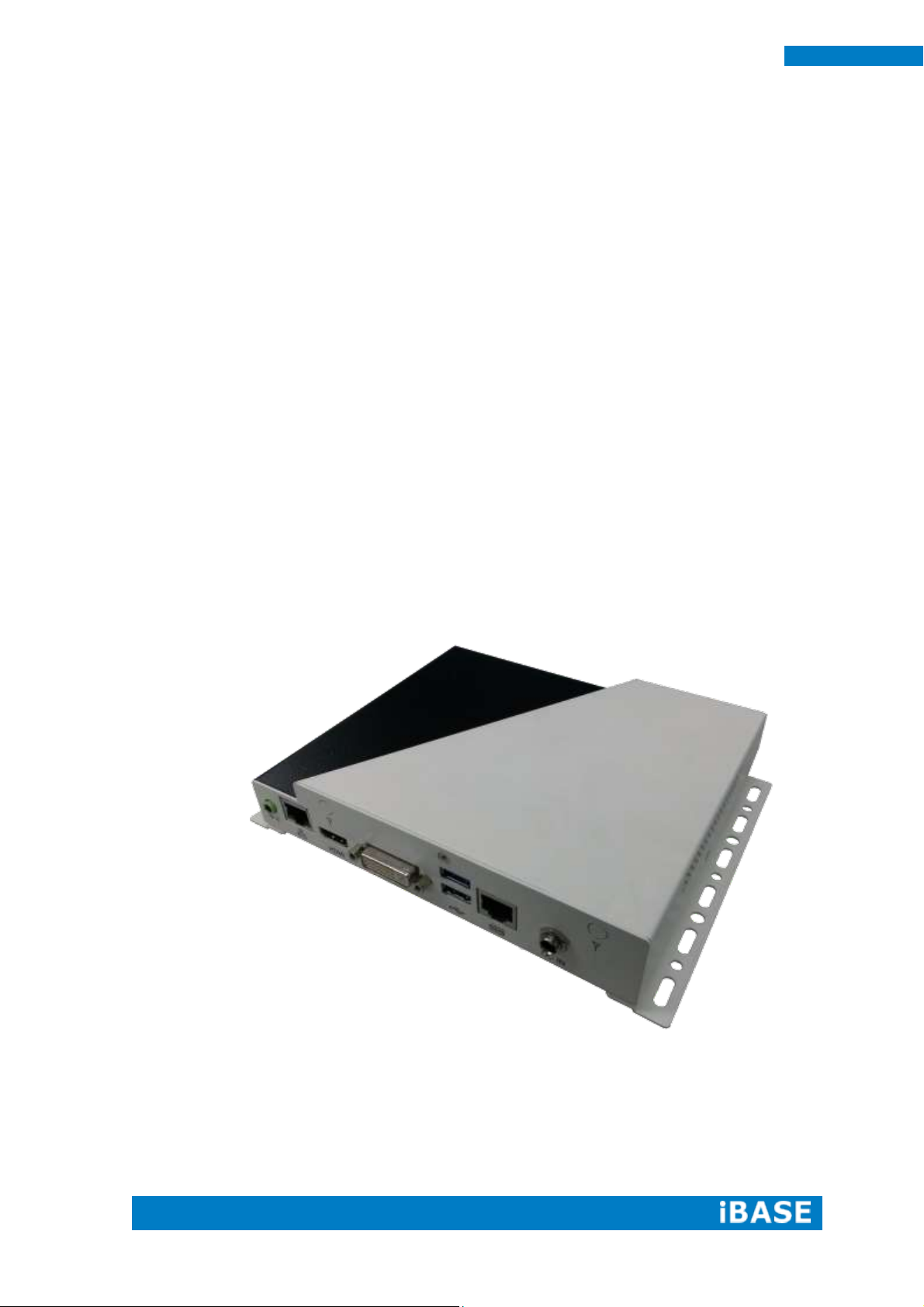
SI-62 Series
User Manual
Page 2

Copyright © 2013 IBASE Technology Inc. All Rights Reserved. 2
2
SI-62 User Manual
Revision
Release Date
V0.1
2014/01/29
V0.2
2014/07/15
V0.3
2014/08/13
Page 3

1
SI-62 User Manual
Copyright © 2013 IBASE Technology Inc. All Rights Reserved.
No part of this manual, including the products and software described in it, may be
reproduced, transmitted, transcribed, stored in a retrieval system, or translated into
any language in any form or by any means, except documentation kept by the
purchaser for backup purposes, without the express written permission of IBASE
Technology INC. (“IBASE”).
Products and corporate names mentioned in this manual may or may not be
registered trademarks or copyrights of their respective companies, and are used for
identification purposes only. All trademarks are the property of their respective
owners.
Every effort has been made to ensure that the contents of this manual are correct and
up to date. However, the manufacturer makes no guarantee regarding the accuracy of
its contents, and reserves the right to make changes without prior notice.
Page 4

2
SI-62 User Manual
Table of Contents
Setting up your system .................................................................................................. 3
Care during use .............................................................................................................. 4
Acknowledgments.......................................................................................................... 5
CHAPTER 1 INTRODUCTION .................................................................................... 6
1.1 General Description ................................................................................................. 6
1.2 System Specifications ............................................................................................... 7
1.2.1 Hardware Specifications ....................................................................................... 7
1.2.2 Dimensions............................................................................................................ 8
1.2.3 I/O View ................................................................................................................ 9
1.3 Exploded View of the SI-62 Assembly ................................................................... 10
1.3.1 Parts Description ................................................................................................. 10
1.4 Packing List ............................................................................................................. 11
1.4.1 Optional Items .................................................................................................... 11
CHAPTER 2 HARDWARE INSTALLATION ..................................................................12
2.1 Installing the CPU ................................................................................................... 12
2.2 Installing the Memory............................................................................................ 13
2.3 Installing the HDD Module..................................................................................... 14
CHAPTER 3 MOTHERBOARD INTRODUCTION .........................................................16
3.1 Introduction ........................................................................................................... 16
3.2 Setting the Jumpers ............................................................................................... 19
3.3 Connector Locations on IB902A ............................................................................. 22
CHAPTER 4 BIOS SETUP .........................................................................................27
CHAPTER 5 DRIVERS INSTALLATION .......................................................................52
5.1 Intel Chipset Software Installation Utility ............................................................. 52
5.2 VGA Drivers Installation ......................................................................................... 55
5.3 Realtek HD Audio Driver Installation ..................................................................... 58
5.4 LAN Drivers Installation ......................................................................................... 60
5.5 Intel® Management Engine Interface .................................................................... 64
5.6 Intel® USB 3.0 Drivers ............................................................................................ 67
Appendix ...............................................................................................................69
Wall Mounting Requirements ...................................................................................... 70
Selecting the Location .................................................................................................. 70
SI-62 Mounting Bracket Solution…..……………..………………………………………………………..71
Page 5

3
SI-62 User Manual
Safety Information
Your SI-62 is designed and tested to meet the latest standards of safety for
information technology equipment. However, to ensure your safety, it is important that
you read the following safety instructions
Setting up your system
Read and follow all instructions in the documentation before you operate your
system.
Do not use this product near water.
Set up the system on a stable surface. Do not secure the system on any unstable
plane.
Do not place this product on an unstable cart, stand, or table. The product may
fall, causing serious damage to the product.
Slots and openings on the chassis are for ventilation. Do not block or cover these
openings. Make sure you leave plenty of space around the system for ventilation.
Never insert objects of any kind into the ventilation openings.
This system should be operated from the type of power indicated on the marking
label. If you are not sure of the type of power available, consult your dealer or
local power company.
Use this product in environments with ambient temperatures between 0˚C and
40˚C.
If you use an extension cord, make sure that the total ampere rating of the
devices plugged into the extension cord does not exceed its ampere rating.
DO NOT LEAVE THIS EQUIPMENT IN AN ENVIRONMENT WHERE
THESTORAGE TEMPERATURE MAY GO BELOW -20° C (-4° F) OR ABOVE
80° C (176° F). THIS COULD DAMAGE THE EQUIPMENT. THE EQUIPMENT
SHOULD BE IN A CONTROLLED ENVIRONMENT.
Page 6

4
SI-62 User Manual
Care during use
Do not walk on the power cord or allow anything to rest on it.
Do not spill water or any other liquids on your system.
When the system is turned off, a small amount of electrical current still flows.
Always unplug all power, and network cables from the power outlets before
cleaning the system.
If you encounter the following technical problems with the product, unplug the
power cord and contact a qualified service technician or your retailer.
The power cord or plug is damaged.
Liquid has been spilled into the system.
The system does not function properly even if you follow the operating
instructions.
The system was dropped or the cabinet is damaged.
Lithium-Ion Battery Warning
CAUTION: Danger of explosion if battery is incorrectly replaced. Replace only with
the same or equivalent type recommended by the manufacturer. Dispose of used
batteries according to the manufacturer’s instructions.
NO DISASSEMBLY
The warranty does not apply to the products that have been disassembled by users
WARNING
HAZARDOUS MOVING PARTS
KEEP FINGERS AND OTHER BODY PARTS AWAY
Page 7

Copyright © 2013 IBASE Technology Inc. All Rights Reserved.
5
IBASE Technology Inc.
Acknowledgments
AMI is a registered trademark of AMI Software International, Inc.
AMD and ATI are registered trademarks of AMD Corporation.
Microsoft Windows is a registered trademark of Microsoft Corporation.
FINTEK is a registered trademark of FINTEK Electronics Corporation.
REALTEK is a registered trademark of REALTEK Electronics Corporation.
All other product names or trademarks are properties of their respective owners.
Page 8
6
SI-62 User Manual
CHAPTER 1 INTRODUCTION
1.1 General Description
SI-62 digital signage player comes with 2nd/3rd Gen. Intel Core i7/i5/i3 Celeron
Quad Core/Dual Core processors and Intel HD Integrated Graphics Engine. It
supports DVI-I and HDMI output, 2 x USB 3.0, 1x RJ45 for RS-232, 1x Gigabit LAN
giving a great selection for data communication in display applications. The compact
design 178 x 150 x 35 mm chassis enables the unit to easily fit into the tightest spaces
behind displays. This new signage player is an ideal solution for graphics intensive
digital signage applications within retail, commerce, education, healthcare and
entertainment.
Page 9
Copyright © 2013 IBASE Technology Inc. All Rights Reserved.
7
IBASE Technology Inc.
Model Name
SI-62
System Mainboard
IB902A
CPU
2nd/3rd Generation Intel® Mobile CoreTM i7/i5/i3/ Celeron®
QC/ DC processors ( TDP <= 35W)
Chipset
Intel® Q77 PCH
Memory
2x DDR3 1066/1333/1600 MHz SO-DIMM, Max. 16GB
(Non-ECC)
I/O Interface
1x HDMI, 1x DVI-I
1x Microjack audio connectors for Line-out
1x Gigabit LAN
2x USB 3.0, 1x RS-232 (RJ45 connector)
1x Power Button with LED light
1x DC Jack
Storage
1x mSATA
1x SATA 3.0 2.5” HDD Dock
Expansion Slots
1x Mini PCI-E(x1) slots for WiFi, 3G and TV tuner options
Power Supply
60W power adaptor
Construction
SGCC
Chassis Color
Black & White
Mounting
Standard system bracket
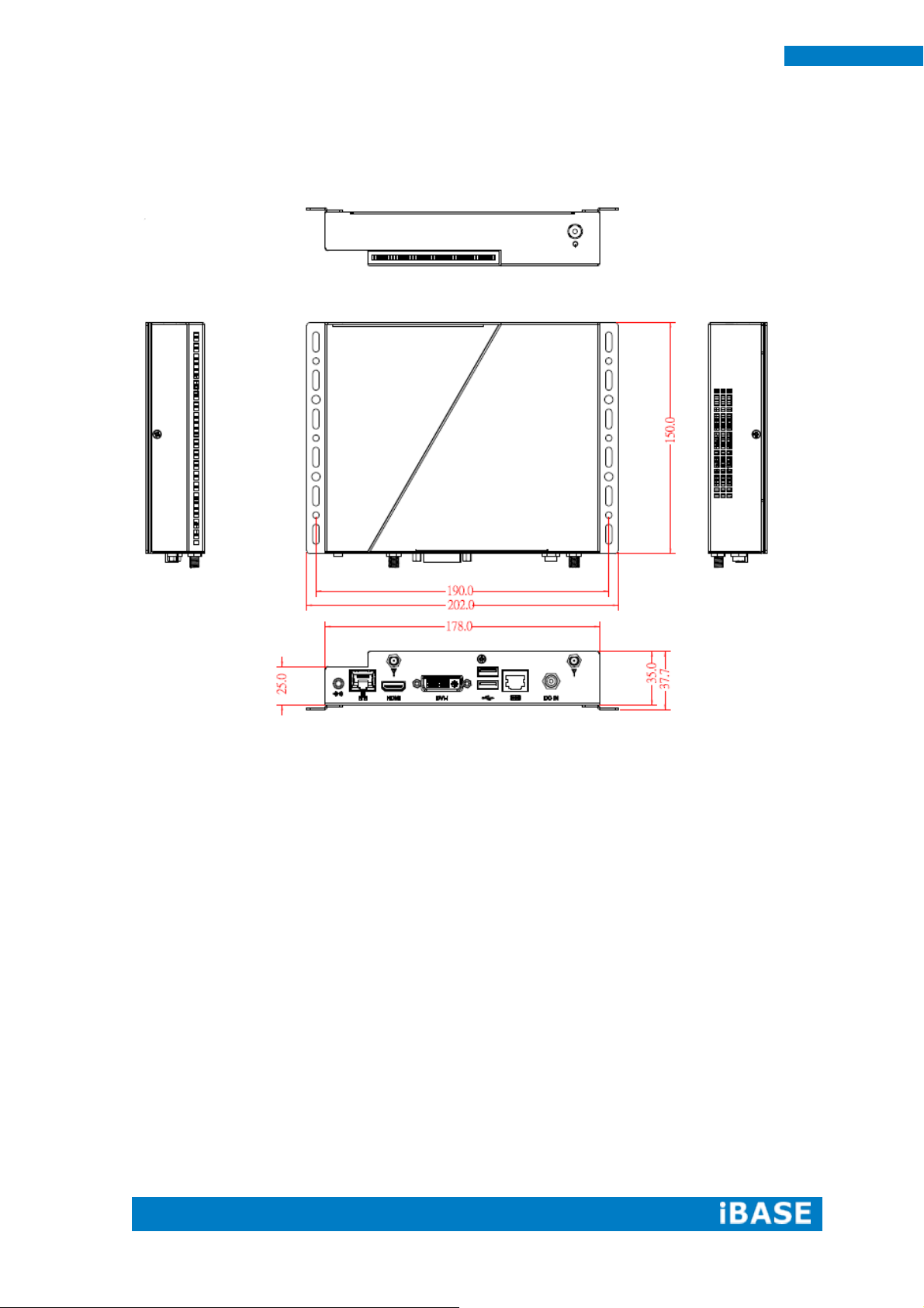
Dimensions
178mm(W) x 150mm(D) x 35mm(H)
Operating Temperature
0°C~ 45°C (32°F~113°F)
Storage Temperature
-20° ~ 80°C (-4°F~176°F)
Relative Humidity
5~90% @45°C (non-condensing)
Vibration
mSATA: 5 Grms/5~500Hz random operation
RoHS
Yes
Certification
CE, FCC class B, CCC and UL
1.2 System Specifications
1.2.1 Hardware Specifications
‧
This specification is subject to change without prior notice.
Page 10
8
SI-62 User Manual
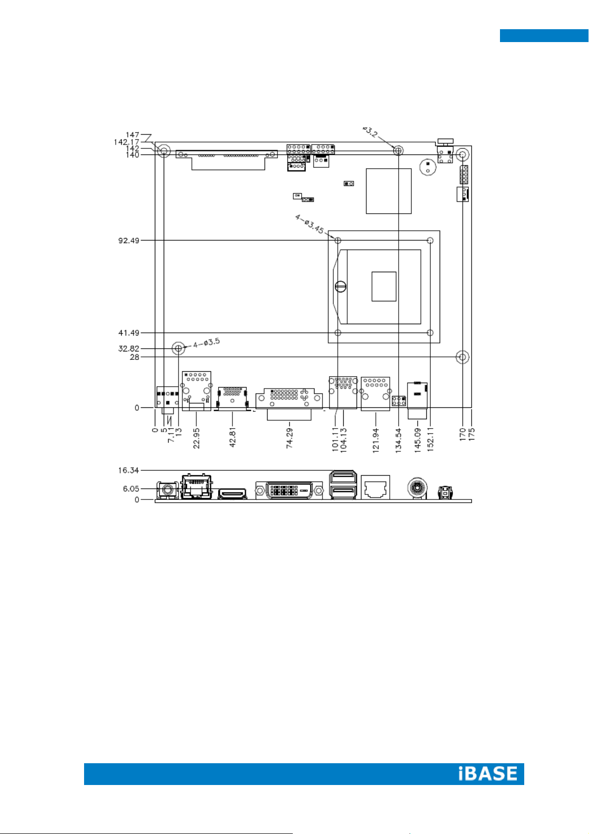
1.2.2 Dimensions
Page 11
Copyright © 2013 IBASE Technology Inc. All Rights Reserved.
9
IBASE Technology Inc.
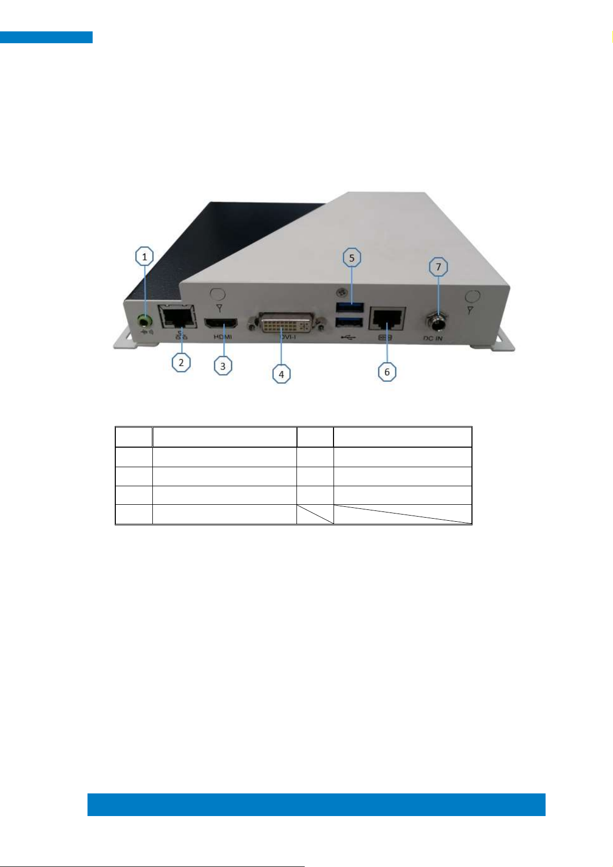
Item
Connector
Item
Connector
1
Line-out
5
2 x USB 3.0
2
Gigabit LAN
6
RJ45 for RS-232
3
HDMI
7
12V DC in
4
DVI
1.2.3 I/O View
Page 12
10
SI-62 User Manual
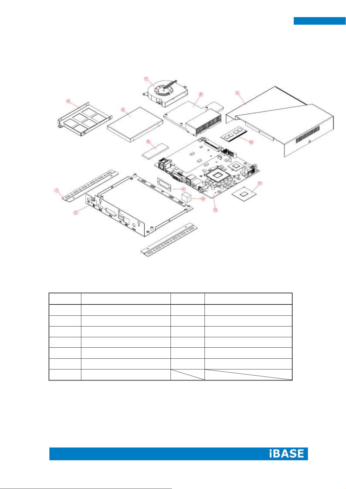
Part No.
Description
Part No.
Description
1
SI-62 side bracket
2
Base
3
Top cover
4
2.5” HDD bracket
5
2.5” HDD
6
Thermal pad
7
Fan
8
Heatsink
9
Gasket
10
Memory
11
CPU
12
DIP PCBA
13
LAN gasket
1.3 Exploded View of the SI-62 Assembly
1.3.1 Parts Description
Page 13
Copyright © 2013 IBASE Technology Inc. All Rights Reserved.
11
IBASE Technology Inc.
Item No.
Description
Qty 1 Driver CD
1
2
Adaptor
1
3
Power Cord
1
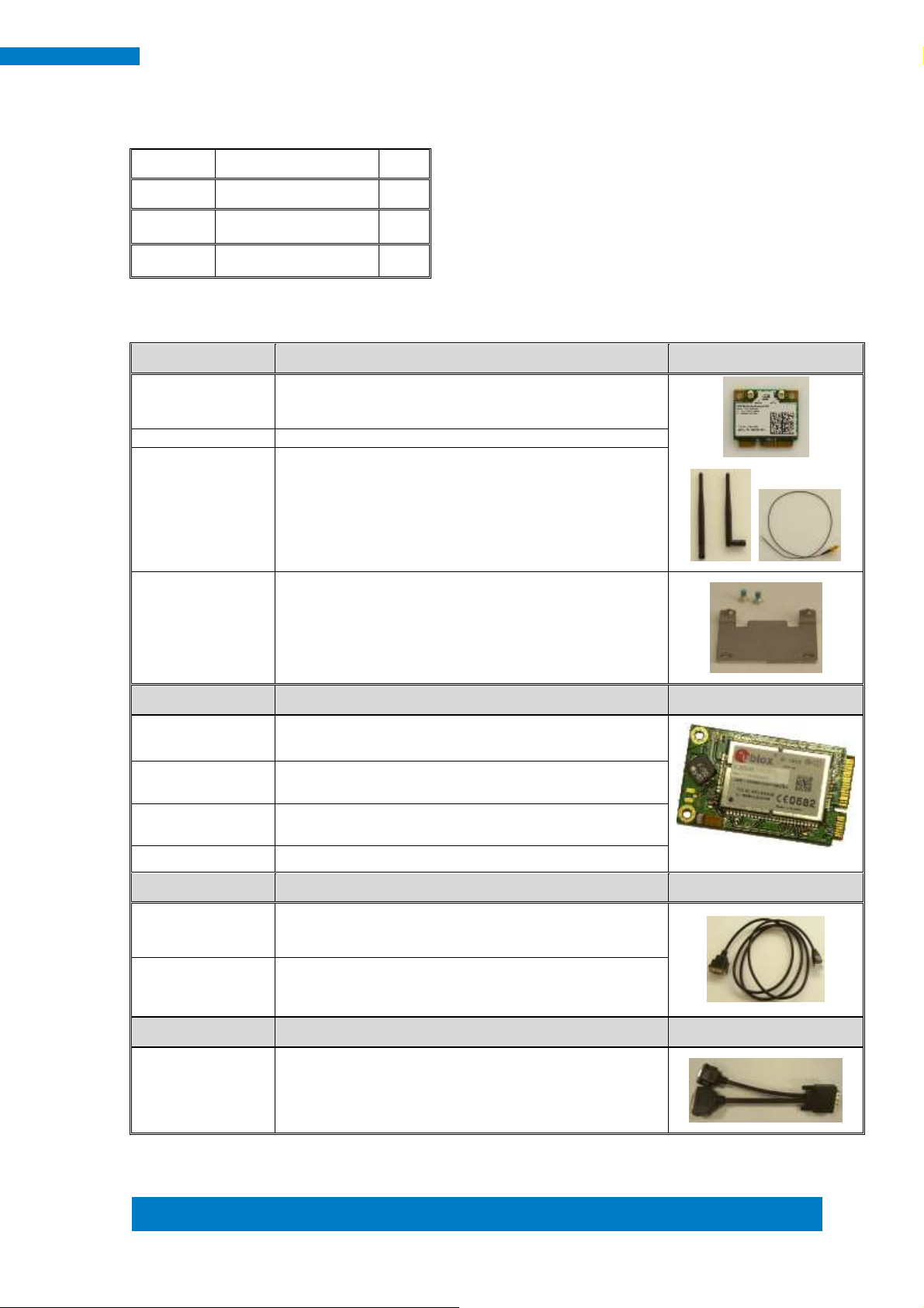
WiFi Solution
Description
QCOM WiFi
module
Wireless LAN Card; 802.11 B/G/N+BT HALF Card
[Q802XKN3B] RoHS (A008WIRELESS00700P)
External Antenna
Wifi Antenna (A055RFA02C2M20800P)
Internal cable-1/2
From Wifi module to Rear/Front panel
(A055RFA0000021000P/A055RFA0000032000P)
Bracket
MPCIE-EXT V-B1 Bracket, RoHS; Extend Half to Full
size. (SC2MPCIEEXT0B1100P)
3G Solution
Description
ZU 202
Wireless; 3.75G UMTS/HSPA [ZU202] RoHS
(A008WIRELESS00520P)
ZU 200
Wireless; 3.75G UMTS/HSPA & GPS Module
[ZU200] RoHS (A008WIRELESS00510P)
Cable
Cable; Antenna-2 30CM P 2pcs
(C501ANT0200300000P)
Antenna
Antenna; 3G, P, 2pcs (A055ANT0921Q2P000P)
COM Port Cable
Description
EXT-311
Cable; EXT-311 2-HD 10C, 150CM; DSUB-9F =>
RJ45-10M RoHS (C501EXT3110A12000P)
EXT-312
Cable; EXT-312 2-HD 10C, 150CM; DSUB-9M =>
RJ45-10M RoHS (C501EXT3120A12000P)
Display Cable
Description
DVI-22
DVI-22 3-HD, 10CM; DVI => DVI, VGA-15 RoHS
(C501DVI2200103000P)
1.4 Packing List
1.4.1 Optional Items
Page 14
12
SI-62 User Manual
NOTE:
Ensure that the CPU heat sink and the CPU top surface are in total contact to
avoid CPU overheating problem that would cause your system to hang or be
unstable.
2 HARDWARE INSTALLATION
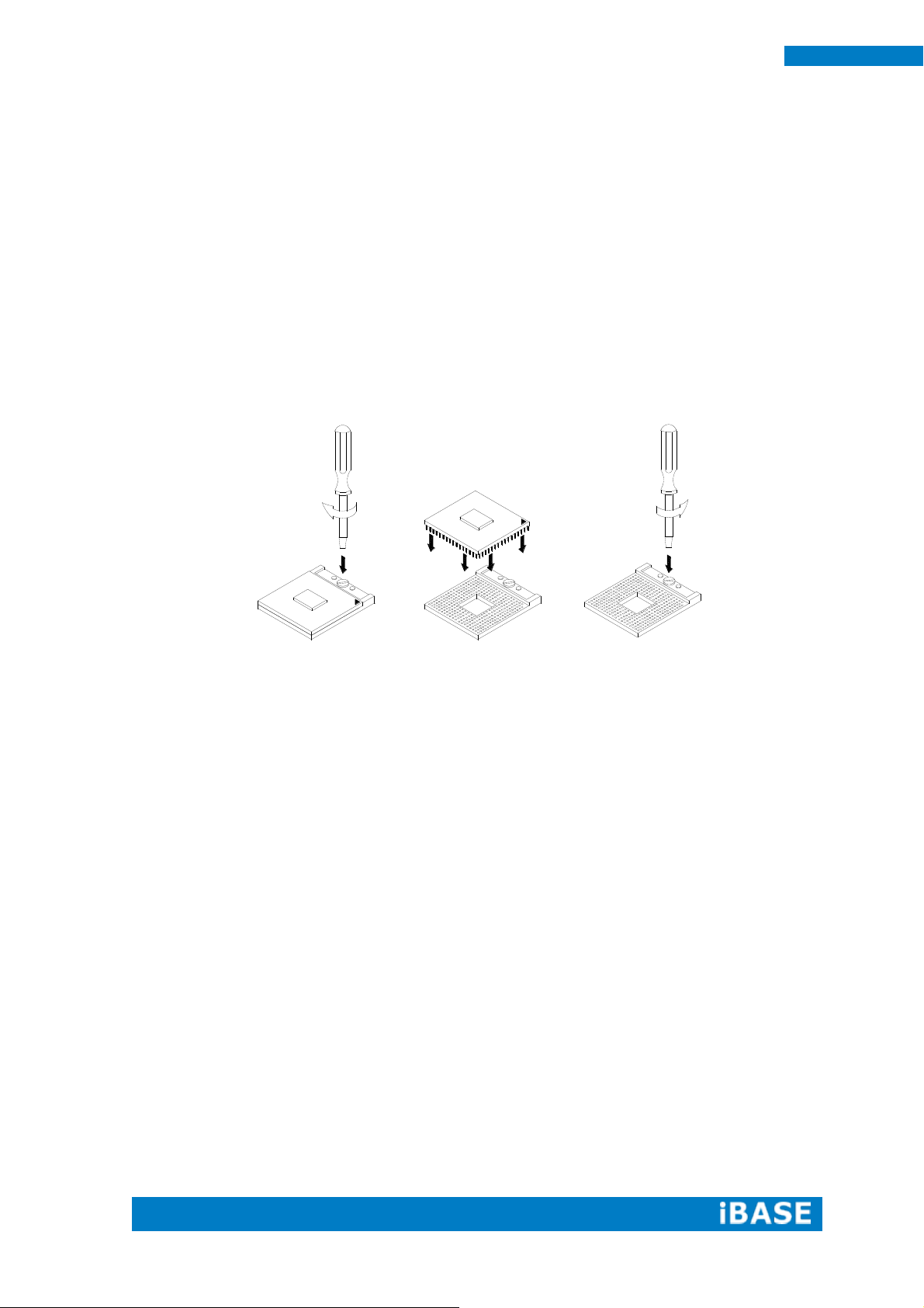
2.1 Installing the CPU
The IB902A board supports rPGA988B socket for Intel® Ivy Bridge Dual Core
mobile processors. The processor socket comes with a screw to secure the processor.
As shown in the picture below, loosen the screw first before inserting the processor.
Place the processor into the socket by making sure the notch on the corner of the
CPU corresponds with the notch on the inside of the socket. Once the processor has
slide into the socket, fasten the screw. Refer to the figures below.
Page 15
Copyright © 2013 IBASE Technology Inc. All Rights Reserved.
13
IBASE Technology Inc.
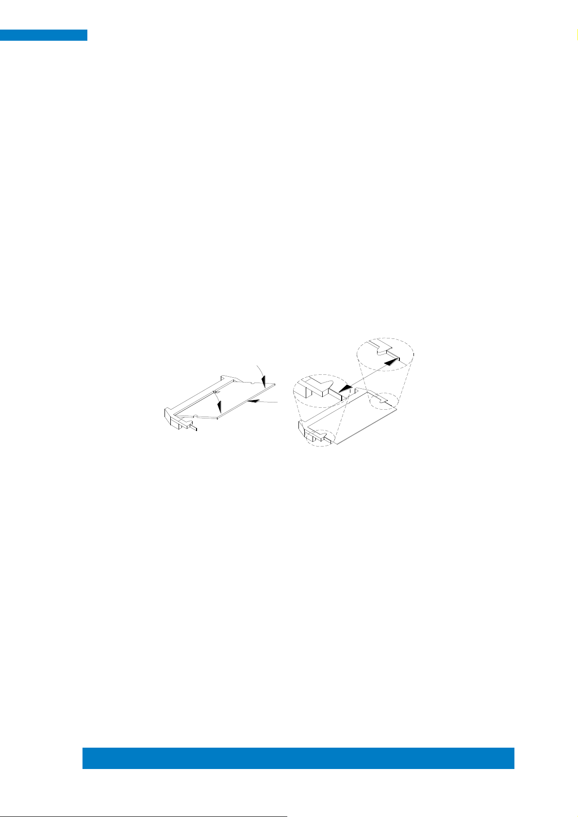
2.2 Installing the Memory
The IB902A board supports two DDR3 memory sockets for a maximum total memory
of 16GB in DDR3 SO-DIMM memory type.
Installing and Removing Memory Modules
To install the DDR3 modules, locate the memory slot on the board and perform the
following steps:
1. Hold the DDR3 module so that the key of the DDR3 module aligned with that on the
memory slot.
2. Gently push the DDR3 module in an upright position until the clips of the slot close to
hold the DDR3 module in place when the DDR3 module touches the bottom of the slot.
3. To remove the DDR3 module, press the clips with both hands.
Page 16
14
SI-62 User Manual
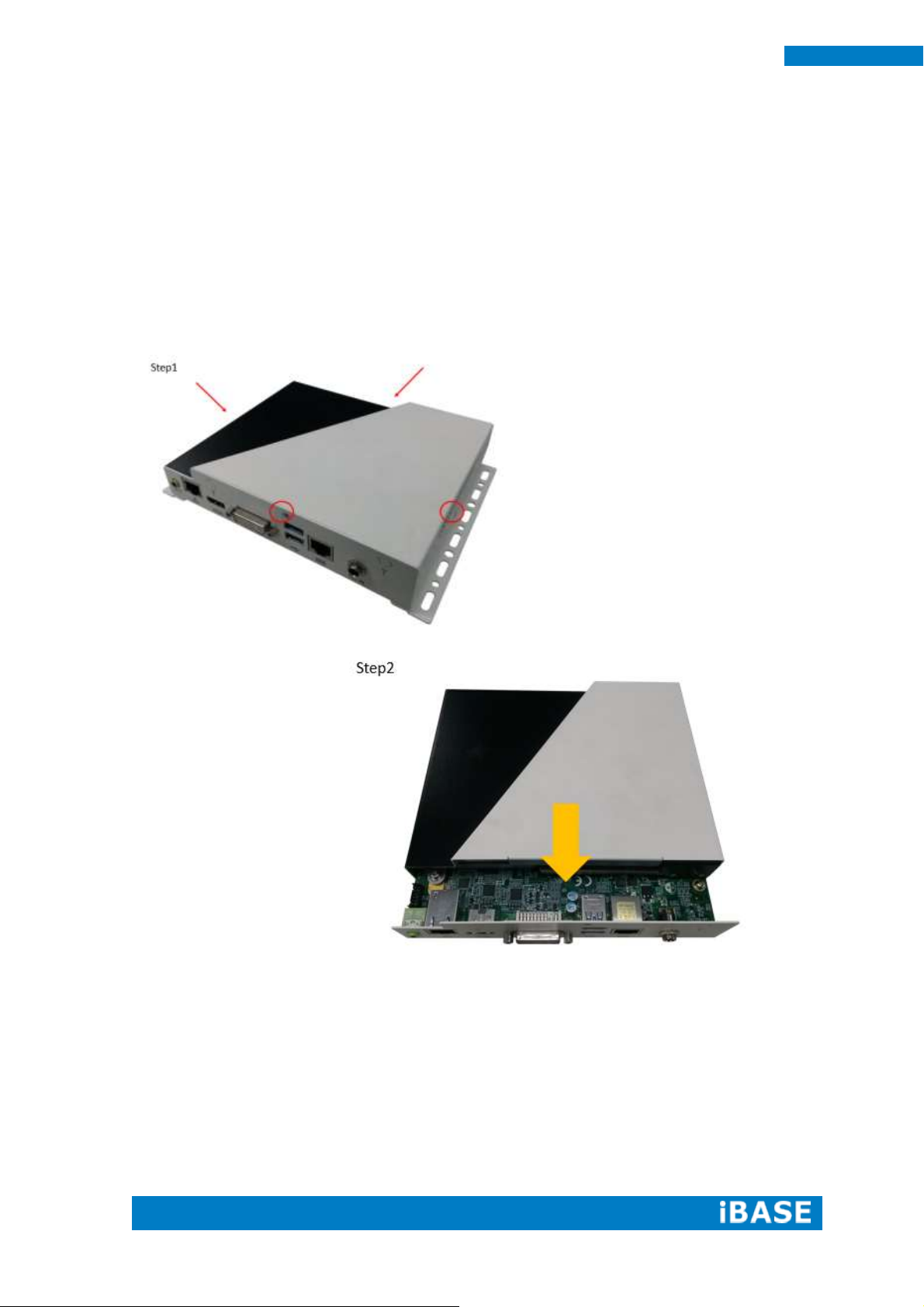
2.3 Installing the HDD Module
HDD Module:
1. Remove the four screws on the sides that are used to secure the top cover to the
chassis. Once all the screws are removed, from the side, push the cover forward to
remove it. See steps1 and 2 in the pictures below.
Page 17
Copyright © 2013 IBASE Technology Inc. All Rights Reserved.
15
IBASE Technology Inc.
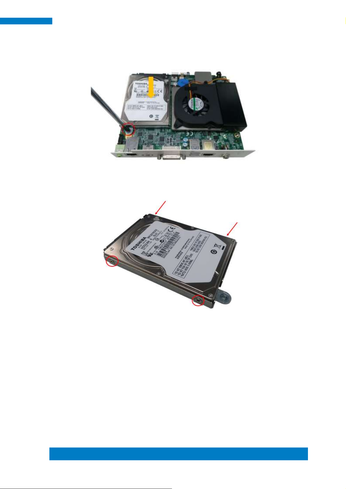
2. Loosen the mounting screws that secure the HDD to the bracket.
3. As in the following the picture’s arrowed direction, push out the HDD module.
4. Loosen the four screws and then replace the HDD module.
Page 18
16
SI-62 User Manual
Specification – Mainboard
Model
IB902A
Form Factor
Customized
CPU
Model
- Intel® 3rd Generation CoreTM I7/I5/I3 mobile processors
- rPGA package, 37.5 mm x 37.5mm
Speed
Up to 3.3GHz
Cache
Up to 6MB
Socket
rPGA 988B (Socket G2)
TDP
35W
Chipset
Model
Intel® QM77 Platform Controller Hub
25 x 27 mm package size
BIOS
Model
AMI BIOS [16MB SPI ROM]
Memory
Max. Support
Intel® Ivy-Bridge mobile processors integrated memory controller
DDRIII 1066/1333/1600 MHz
- SO-DIMM [204-pin parallel type] x 2 (Non-ECC), Max. 16GB
CHAPTER 3 MOTHERBOARD INTRODUCTION
3.1 Introduction
The IB902A motherboard is based on the latest Intel® QM77 chipset. The
platform supports 3rd generation Intel® Core processor family with rPGA988B
packing and features an integrated dual-channel DDR3 memory controller as well as
a graphics core.
The latest Intel® processors provide advanced performance in both computing
and graphics quality. This meets the requirement of customers in the gaming, POS,
digital signage and server market segment.
The QM77 chipset is made with 22-nanometer technology that supports Intel’s
first processor architecture to unite the CPU and the graphics core on the transistor
level. The IB902A board utilizes the dramatic increase in performance provided this
Intel’s latest cutting-edge technology. Measuring 175mm x 147mm, the IB902A offers
fast 6Gbps SATA support (1 ports), USB3.0 (2 ports) and interfaces for DVI-I and
HDMI displays.
Page 19
Copyright © 2013 IBASE Technology Inc. All Rights Reserved.
17
IBASE Technology Inc.
Functionality
Display
- Intel 3rd Generation CoreTM mobile processor integrated Gfx, Direct X 11,
OpenGL 3.1, Open CL 1.1
DVI-I X 1 (thru Level shifter ASM1442)
HDMI X 1(thru Level shifter ASM1442)
LAN / PHY
InteI 82579V PCI-E Gigabit LAN for QM77 (Real panel) for single GbE (Rear)
USB
USB 2.0 host controller [Panther Point integrated]
- 1 port via MiniPCIe socket; 2 ports via pin-header
USB 3.0 host controller [Panther Point integrated]
- 2 ports in the rear panel
Serial ATA
Intel® QM77 PCH built-in SATA controller
1x SATA 3.0 2.5” HDD Dock
Audio
Intel® QM77 PCH built-in High Definition Audio controller + Realtek ALC892 w/ 7.1
channels (Line In/Mic In/Line Out)
LPC I / O
Fintek F81866AD-I (128-pin LQFP [14mm x 14 mm])
RJ45 connector x1 for COM 1 (RS232) (Rear)
CPU fan & SYS fan (4-pin connector x 2, supports PWM)
iAMT
None
Expansion slot
Mini PCI-Express x 1 port [Full-sized] w/mSATA +USB 2.0 support
Edge I/O
Display
1x DVI-I connector (Rear); 1x HDMI connector (Rear)
LAN / PHY
1x RJ-45 connector (Rear)
USB
1x USB (3.0) dual stack (Rear)
LPC I / O
1x RS-232 (RJ45) (Rear)
Other
1x Power Jack (+12V DC) (Rear); 1x Power On/Reset button with LED (Front)
Internal I/O
FAN
CPU fan & SYS fan (4-pin connector x2
Serial ATA
Intel® QM77 PCH built-in SATA controller
1x SATA 3.0 2.5” HDD Dock
Memory
2x DDR 3 SO-DIMM parallel memory slots
Expansion slot
Mini PCI-Express x 1 port [Full-sized] w/mSATA +USB 2.0 supporting
Other
iSMART function, Auto-scheduler, Power resume
Add-On Feature
Watchdog
Yes (256 segments, 0, 1, 2…255 sec/min)
AMT
Yes
Other
iSMART function
Dimensions
PCB
175mm x 147mm
Power Supply
Power
Power Jack (+12V DC)
Environmental
Temperature
Operating: 0°C~ 40°C (32°F~104°F)
Storage: -20oC to 80oC(-4oF~167oF)
Humidity
10%~90% (non-condensing)
Shock
IBASE Standard Test
Vibration
IBASE Standard Test
Certification
RoHS
Other
CE/FCC
Page 20
18
SI-62 User Manual
Board Dimensions
Page 21
Copyright © 2013 IBASE Technology Inc. All Rights Reserved.
19
IBASE Technology Inc.
3.2 Setting the Jumpers
Jumpers are used on IB902A to select various settings and features according to
your needs and applications. Contact your supplier if you have doubts about the best
configuration for your needs.
Jumper Locations on IB902A
Page 22
20
SI-62 User Manual
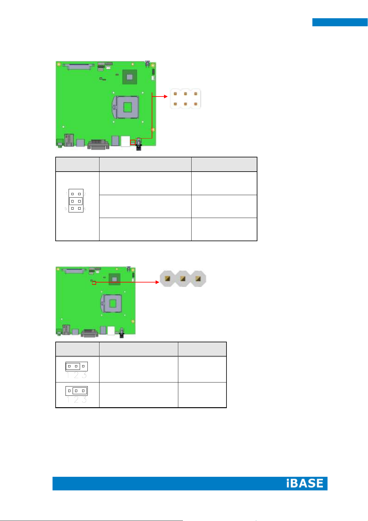
JP1
Setting
Function
Pin 1-3
Short/Closed
+12V
Pin 3-4
Short/Closed
RI
Pin 3-5
Short/Closed
+5V
J4
Setting
Function
Pin 1-2
Short/Closed
Normal
Pin 2-3
Short/Closed
Clear CMOS
3 1
JP1: COM1 RS232 RI/+5V/+12V Power Setting
J4: Clear CMOS Contents
Page 23

Copyright © 2013 IBASE Technology Inc. All Rights Reserved.
21
IBASE Technology Inc.
J7
Flash Descriptor Security
Override
Open
Disabled (Default)
Close
Enabled
J10
Reset BTN
Open
Disabled (Default)
Close
Enabled
1 2
1
2
J7: Flash Descriptor Security Override (Factory use only)
J10: Reset BTN
Page 24

22
SI-62 User Manual
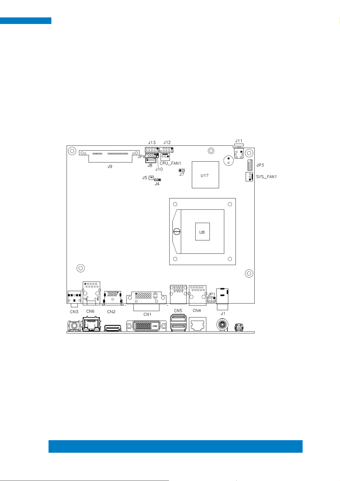
3.3 Connector Locations on IB902A
Page 25

Copyright © 2013 IBASE Technology Inc. All Rights Reserved.
23
IBASE Technology Inc.
Signal Name
Pin #
Pin #
Signal Name
DATA 2-
1
16
HOT POWER
DATA 2+
2
17
DATA 0-
Shield 2/4
3
18
DATA 0+
DATA 4-
4
19
SHIELD 0/5
DATA 4+
5
20
DATA 5-
DDC CLOCK
6
21
DATA 5+
DDC DATA
7
22
SHIELD CLK
N.C
8
23
CLOCK -
DATA 1-
9
24
CLOCK +
DATA 1+
10
C1
Analog Red
SHIELD 1/3
11
C2
Analog Green
DATA 3-
12
C3
Analog Blue
DATA 3+
13
C4
Analog HYNC
DDC POWER
14
C5
A GROUND2
A GROUND 1
15
C6
A GROUND3
Pin #
Signal Name
1
DSR, Data set ready
2
GND, ground
3
GND, ground
4
TXD, Transmit data
5
RXD, Receive data
6
DCD, Data carrier detect
7
DTR, Data terminal ready
8
CTS, Clear to send
9
RTS, Request to send
10
RI, Ring indicator
CN1: DVI-I Connector
CN2: HDMI Connector
CN3: HDA Audio Connector
CN4: LAN Port To COM1
Page 26

24
SI-62 User Manual
Pin #
Signal Name
1
BAT
2
Ground
CN5: USB3 Connector
CN6: Gigabit LAN (82579V)
J1: +12V Power Supply Connector
J5: Battery 1/2AA Connector
Page 27

Copyright © 2013 IBASE Technology Inc. All Rights Reserved.
25
IBASE Technology Inc.
Signal Name
Pin #
Pin #
Signal Name
Vcc
1 2 Vcc
D0-
3 4 D1-
D0+
5 6 D1+
Ground
7 8 Ground
Key
9
10
NC
Signal Name
Pin #
Pin #
Signal Name
Ground
1 2 +5V
Out3
3 4 Out1
Out2
5 6 Out0
IN3
7 8 IN1
IN2
9
10
IN0
J9: SATA3 Connector
J11: Power Button
J12: USB2 Connector
J13: Digital I/O Connector (4 in, 4 out)
J14: DDR3 SO-DIMM Channel A
J15: DDR3 SO-DIMM Channel B
J16: Mini-PCIE Connector and mSATA
Page 28

26
SI-62 User Manual
Pin #
Signal Name
1
Ground
2
+12V
3
Rotation detection
Pin #
Signal Name
1
Ground
2
+12V
3
Rotation detection
CPU_FAN1: CPU Fan Power Connector
SYS_FAN2: System Fan Power Connector
JP3: SPI Flash connector (Factory use only)
JP4: LPC debug Connector (Factory use only)
Page 29

Copyright © 2013 IBASE Technology Inc. All Rights Reserved.
27
IBASE Technology Inc.
Warning:
It is strongly recommended that you avoid making any
changes to the chipset defaults. These defaults have been
carefully chosen by both AMI and your system manufacturer
to provide the absolute maximum performance and
reliability. Changing the defaults could cause the system to
become unstable and crash in some cases.
CHAPTER 4 BIOS SETUP
This chapter describes the different settings available in the AMI BIOS that
comes with the board. The topics covered in this chapter are as follows:
BIOS Introduction
The BIOS (Basic Input/Output System) installed in your computer system’s ROM
supports Intel processors. The BIOS provides critical low-level support for a standard
device such as disk drives, serial ports and parallel ports. It also password protection
as well as special support for detailed fine-tuning of the chipset controlling the entire
system.
BIOS Setup
The BIOS provides a Setup utility program for specifying the system configurations
and settings. The BIOS ROM of the system stores the Setup utility. When you turn on
the computer, the BIOS is immediately activated. Pressing the <Del> key immediately
allows you to enter the Setup utility. If you are a little bit late pressing the <Del> key,
POST (Power On Self Test) will continue with its test routines, thus preventing you
from invoking the Setup. If you still wish to enter Setup, restart the system by pressing
the ”Reset” button or simultaneously pressing the <Ctrl>, <Alt> and <Delete> keys.
You can also restart by turning the system Off and back On again. The following
message will appear on the screen:
Press <DEL> or <F2> to Enter Setup
In general, you press the arrow keys to highlight items, <Enter> to select, the <PgUp>
and <PgDn> keys to change entries, <F1> for help and <Esc> to quit.
When you enter the Setup utility, the Main Menu screen will appear on the screen.
The Main Menu allows you to select from various setup functions and exit choices.
Page 30

28
SI-62 User Manual
Main Advanced Chipset Boot Security Save & Exit
BIOS Information
Choose the system default language
→ ← Select Screen
↑↓ Select Item
Enter: Select
+- Change Field
F1: General Help
F2: Previous Values
F3: Optimized Default
F4: Save ESC: Exit
Total memory
8176 MB (DDR3)
Memory Frequency
1333Mhz
System Date
[Tue 01/20/2013]
System Time
[00.00.00]
Access Level
Administrator
Main Settings
Aptio Setup Utility – Copyright © 2011 American Megatrends, Inc.
System Language
Choose the system default language.
System Date
Set the Date. Use Tab to switch between Data elements.
System Time
Set the Time. Use Tab to switch between Data elements.
Page 31

Copyright © 2013 IBASE Technology Inc. All Rights Reserved.
29
IBASE Technology Inc.
Main Advanced Chipset Boot Security Save & Exit
→ ← Select Screen
↑↓ Select Item
Enter: Select
+- Change Field
F1: General Help
F2: Previous Values
F3: Optimized Default
F4: Save ESC: Exit
► PCI Subsystem Settings
► ACPI Settings
► Wake up event setting
► CPU Configuration
► SATA Configuration
► Shutdown Temperature Configuration
► iSmart Controller
► AMT Configuration
► USB Configuration
► F81866 Super IO Configuration
► F81866 H/W Monitor
► CPU PPM Configuration
►Sandybridge DTS Configuration
Advanced Settings
This section allows you to configure and improve your system and allows you to set up some
system features according to your preference.
Aptio Setup Utility
Page 32

30
SI-62 User Manual
Main Advanced Chipset Boot Security Save & Exit
PCI Bus Driver Version V 2.0502
→ ← Select Screen
↑↓ Select Item
Enter: Select
+- Change Field
F1: General Help
F2: Previous Values
F3: Optimized Default
F4: Save ESC: Exit
PCI 64bit Resources Handing
Above 4G Decoding
Disabled
PCI Common Settings
PCI Latency Timer
32 PCI Bus Clocks
VGA Palette Snoop
Disabled
PERR# Generation
Disabled
SERR# Generation
Disabled
► PCI Express Settings
PCI Subsystem Settings
Aptio Setup Utility
Above 4G Decoding
Enables or Disables 64bit capable devices to be decoded in above 4G address space
(only if system supports 64 bit PCI decoding).
PCI Latency Timer
Value to be programmed into PCI Latency Timer Register.
VGA Palette Snoop
Enables or disables VGA Palette Registers Snooping.
PERR# Generation
Enables or disables PCI device to generate PERR#.
SERR# Generation
Enables or disables PCI device to generate SERR#.
PCI Express Settings
Change PCI Express devices settings.
Page 33

Copyright © 2013 IBASE Technology Inc. All Rights Reserved.
31
IBASE Technology Inc.
Main Advanced Chipset Boot Security Save & Exit
PCI Express Device Register Settings
→ ← Select Screen
↑↓ Select Item
Enter: Select
+- Change Field
F1: General Help
F2: Previous Values
F3: Optimized Default
F4: Save ESC: Exit
Relaxed Ordering
Disabled
Extended Tag
Disabled
No Snoop
Enabled
Maximum Payload
Auto
Maximum Read Request
Auto
PCI Express Link Register Settings
ASPM Support
Disabled
WARNING: Enabling ASPM may cause
Disabled
some PCI-E devices to fail
Extended Synch
Disabled
Link Training Retry
5
Link Training Timeout (uS)
100
Unpopulated Links
Keep Link ON
PCI Express Settings
Aptio Setup Utility
Relaxed Ordering
Enables or disables PCI Express Device Relaxed Ordering.
Extended Tag
If ENABLED allows device to use 8-bit Tag field as a requester.
No Snoop
Enables or disables PCI Express Device No Snoop option.
Maximum Payload
Set Maximum Payload of PCI Express Device or allow System BIOS to select the
value.
Maximum Read Request
Set Maximum Read Request Size of PCI Express Device or allow System BIOS to
select the value.
ASPM Support
Set the ASPM Level: Force L0s – Force all links to L0s State:
AUTO – BIOS auto configure: DISABLE – Disables ASPM.
Extended Synch
If ENABLED allows generation of Extended Synchronization patterns.
Page 34

32
SI-62 User Manual
Link Training Retry
Defines number of Retry Attempts software will take to retrain the link if previous
training attempt was unsuccessful.
Link Training Timeout (uS)
Defines number of Microseconds software will wait before polling ‘Link Training’ bit in
Link Status register. Value range from 10 to 1000 uS.
Unpopulated Links
In order to save power, software will disable unpopulated PCI Express links, if this
option set to ‘Disable Link’.
Page 35

Copyright © 2013 IBASE Technology Inc. All Rights Reserved.
33
IBASE Technology Inc.
Main Advanced Chipset Boot Security Save & Exit
ACPI Settings
→ ← Select Screen
↑↓ Select Item
Enter: Select
+- Change Field
F1: General Help
F2: Previous Values
F3: Optimized Default
F4: Save ESC: Exit
Enable Hibernation
Enabled
ACPI Sleep State
S1 only(CPU Stop Clock)
Lock Legacy Resources
S3 Video Repost
Disabled
Disabled
Main Advanced Chipset Boot Security Save & Exit
→ ← Select Screen
↑↓ Select Item
Enter: Select
+- Change Field
F1: General Help
F2: Previous Values
F3: Optimized Default
F4: Save ESC: Exit
Wake on Ring
Disabled
Wake on PCIE Wake Event
Disabled
ACPI Settings
Aptio Setup Utility
Enable Hibernation
Enables or Disables System ability to Hibernate (OS/S4 Sleep State). This option may
be not effective with some OS.
ACPI Sleep State
Select ACPI sleep state the system will enter, when the SUSPEND button is pressed.
Lock Legacy Resources
Enabled or Disabled Lock of Legacy Resources.
S3 Video Repost
Enable or disable S3 Video Repost.
Wake up event settings
Aptio Setup Utility
Wake on PCIE PME Wake Event
The options are Disabled and Enabled.
Page 36

34
SI-62 User Manual
Main Advanced Chipset Boot Security Save & Exit
CPU Configuration
→ ← Select Screen
↑↓ Select Item
Enter: Select
+- Change Field
F1: General Help
F2: Previous Values
F3: Optimized Default
F4: Save ESC: Exit
Intel® Core ™ i5-3610ME CPU @ 2.70GHz
Processor Stepping
306a9
Microcode Revision
c
Max CPU Speed
2700 MHz
Min CPU Speed
1200 MHz
CPU Speed
2700 MHz
Processor Cores
2
Intel HT Technology
Supported
Intel VT-x Technology
Supported
Intel SMX Technology
Supported
64-bit
Supported
Hyper-threading
Enabled
Active Processor Cores
All
Limit CPUID Maximum
Disabled
Execute Disable Bit
Enabled
Intel Virtualization Technology
Disabled
Adjacent Cache Line Prefetch
Enabled
CPU Configuration
Aptio Setup Utility
Hyper-threading
Enabled for Windows XP and Linux (OS optimized for Hyper-Threading Technology)
and Disabled for other OS (OS not optimized for Hyper-Threading Technology). When
Disabled, only one thread per enabled core is enabled.
Active Processor Cores
Number of cores to enable in each processor package.
Limit CPUID Maximum
Disabled for Windows XP.
Execute Disable Bit
XD can prevent certain classes of malicious buffer overflow attacks when combined
with a supporting OS (Windows Server 2003 SP1, Windows XP SP2, SuSE Linux 9.2,
RedHat Enterprise 3 Update 3.)
Intel Virtualization Technology
When enabled, a VMM can utilize the additional hardware capabilities provided by
Vanderpool Technology.
Adjacent Cache Line Prefetch
To turn on/off prefetching of adjacent cache lines.
Page 37

Copyright © 2013 IBASE Technology Inc. All Rights Reserved.
35
IBASE Technology Inc.
Main Advanced Chipset Boot Security Save & Exit
→ ← Select Screen
↑↓ Select Item
Enter: Select
+- Change Field
F1: General Help
F2: Previous Values
F3: Optimized Default
F4: Save ESC: Exit
SATA Controller(s)
Enabled
SATA Mode Selection
AHCI
SATA Port0
Empty
Software Preserve
Unknown
SATA Port5
Empty
Software Preserve
Unknown
SATA Configuration
SATA Devices Configuration.
Aptio Setup Utility
SATA Controller(s)
Enable / Disable Serial ATA Controller.
SATA Mode Selection
(1) IDE Mode.
(2) AHCI Mode.
Page 38

36
SI-62 User Manual
Main Advanced Chipset Boot Security Save & Exit
→ ← Select Screen
↑↓ Select Item
Enter: Select
+- Change Field
F1: General Help
F2: Previous Values
F3: Optimized Default
F4: Save ESC: Exit
APCI Shutdown Temperature
Disabled
Main Advanced Chipset Boot Security Save & Exit
iSmart Controller
→ ← Select Screen
↑↓ Select Item
Enter: Select
+- Change Field
F1: General Help
F2: Previous Values
F3: Optimized Default
F4: Save ESC: Exit
Power-On after Power failure
Disable
Schedule Slot 1
None
Schedule Slot 2
None
Shutdown Temperature Configuration
Aptio Setup Utility
ACPI Shutdown Temperature
The default setting is Disabled.
iSmart Controller
Aptio Setup Utility
ISmart Controller
Setup the power on time for the system.
Schedule Slot 1 / 2
Setup the hour/minute for system power on.
Page 39

Copyright © 2013 IBASE Technology Inc. All Rights Reserved.
37
IBASE Technology Inc.
Main Advanced Chipset Boot Security Save & Exit
→ ← Select Screen
↑↓ Select Item
Enter: Select
+- Change Field
F1: General Help
F2: Previous Values
F3: Optimized Default
F4: Save ESC: Exit
Intel AMT
Enabled
BIOS Hotkey Pressed
Disabled
MEBx Selection Screen
Disabled
Hide Un-Configure ME Confirmation
Disabled
Un-Configure ME
Disabled
Amt Wait Timer
0
Activate Remote Assistance Process
Disabled
USB Configure
Enabled
PET Progress
Enabled
AMT CIRA Timeout
0
Watchdog
Disabled
OS Timer
0
BIOS Timer
0
AMT Configuration
Aptio Setup Utility
AMT Configuration
This configuration is supported only with IB902AVF (with iAMT function). Options are
Enabled and Disabled.
Note: iAMT H/W is always enabled. This option just controls the BIOS extension
execution. If enabled, this requires additional firmware in the SPI device.
Unconfigure ME
This configuration is supported only with IB902AVF (with iAMT function). Perform
AMT/ME unconfigure without password operation.
Amt Wait Timer
Set timer to wait before sending ASF_GET_BOOT_OPTIONS.
Activate Remote Assistance Process
Trigger CIRA boot.
PET Progress
User can Enable/Disable PET Events progress to receive PET events or not.
Watchdog Timer
This configuration is supported only with IB902AVF (with iAMT function).
Enable/Disable Watchdog Timer.
Page 40

38
SI-62 User Manual
Main Advanced Chipset Boot Security Save & Exit
USB Configuration
→ ← Select Screen
↑↓ Select Item
Enter: Select
+- Change Field
F1: General Help
F2: Previous Values
F3: Optimized Default
F4: Save ESC: Exit
USB Devices:
2 Hubs
Legacy USB Support
Enabled
USB3.0 Support
Enabled
XHCI Hand-off
Enabled
EHCI Hand-off
Enabled
USB hardware delays and time-outs:
USB Transfer time-out
20 sec
Device reset tine-out
20 sec
Device power-up delay
Auto
USB Configuration
Legacy USB Support
AUTO option disables legacy support if no USB devices are connected.
DISABLE option will keep USB devices available only for EFI applications.
USB3.0 Support
Enable/Disable USB3.0 (XHCI) Controller support.
XHCI Hand-off
This is a workaround for OSes without XHCI hand-off support. The XHCI ownership
change should be claimed by XHCI driver.
EHCI Hand-off
Enabled/Disabled. This is a workaround for OSes without EHCI hand-off support. The
EHCI ownership change should be claimed by EHCI driver.
USB Transfer time-out
The time-out value for Control, Bulk, and Interrupt transfers.
Device reset tine-out
USB mass Storage device start Unit command time-out.
Device power-up delay
Maximum time the device will take before it properly reports itself to the Host
Controller. ‘Auto’ uses default value: for a Root port it is 100ms, for a Hub port the
delay is taken from Hub descriptor.
Page 41

Copyright © 2013 IBASE Technology Inc. All Rights Reserved.
39
IBASE Technology Inc.
Main Advanced Chipset Boot Security Save & Exit
F81866 Super IO Configuration
→ ← Select Screen
↑↓ Select Item
Enter: Select
+- Change Field
F1: General Help
F2: Previous Values
F3: Optimized Default
F4: Save ESC: Exit
► Serial Port 0 Configuration
F81866 Super IO Configuration
Aptio Setup Utility
Serial Port Configuration
Set Parameters of Serial Ports. User can Enable/Disable the serial port and Select
an optimal settings for the Super IO Device.
Page 42

40
SI-62 User Manual
Main Advanced Chipset Boot Security Save & Exit
PC Health Status
→ ← Select Screen
↑↓ Select Item
Enter: Select
+- Change Field
F1: General Help
F2: Previous Values
F3: Optimized Default
F4: Save ESC: Exit
CPU temperature
+32 C
SYS temperature
+35 C
FAN1 Speed
5154 RPM
FAN2 Speed
N/A
Vcore
+0.904 V
Vcc5V
+5.003 V
Vcc12V
+12.408 V
+1.5V
+1.512 V
Vcc3.3V
+3.296 V
Fan1 smart fan control
Disabled
Fan2 smart fan control
Disabled
F81866 H/W Monitor
Aptio Setup Utility
Temperatures/Voltages
These fields are the parameters of the hardware monitoring function feature of the
motherboard. The values are read-only values as monitored by the system and show
the PC health status.
Fan1/Fan2 Smart Fan Control
This field enables or disables the smart fan feature. At a certain temperature, the fan
starts turning. Once the temperature drops to a certain level, it stops turning again.
Page 43

Copyright © 2013 IBASE Technology Inc. All Rights Reserved.
41
IBASE Technology Inc.
Main Advanced Chipset Boot Security Save & Exit
CPU PPM Configuration
→ ← Select Screen
↑↓ Select Item
Enter: Select
+- Change Field
F1: General Help
F2: Previous Values
F3: Optimized Default
F4: Save ESC: Exit
EIST
Enabled
Turbo Mode
Enabled
Main Advanced Chipset Boot Security Save & Exit
Sandybridge DTS Configuration
→ ← Select Screen
↑↓ Select Item
Enter: Select
+- Change Field
F1: General Help
F2: Previous Values
F3: Optimized Default
F4: Save ESC: Exit
CPU DTS
Disable
CPU PPM Configuration
EIST
Enable/Disable Intel SpeedStep.
Aptio Setup Utility
Sandybridge DTS Configuration
Aptio Setup Utility
CPU DTS
Disabled: ACPI thermal management uses EC reported temperature values.
Enabled: ACPI thermal management uses DTS SMM mechanism to obtain CPU
temperature values.
Out of Spec: ACPI Thermal Management uses EC reported temperature values and
TS SMM is used to handle Out of Spec.
Page 44

42
SI-62 User Manual
Main Advanced Chipset Boot Security Save & Exit
► PCH-IO Configuration
► System Agent (SA) Configuration
Main Advanced Chipset Boot Security Save & Exit
Intel PCH RC Version 1.1.0.0
→ ← Select Screen
↑↓ Select Item
Enter: Select
+- Change Field
F1: General Help
F2: Previous Values
F3: Optimized Default
F4: Save ESC: Exit
Intel PCH SKU Name
QM77
Intel PCH Rev ID
O4/C1
► PCI Express Configuration
► USB Configuration
► PCH Azalia Configuration
PCH LAN Controller
Enabled
Wake on LAN
Disabled
Board Capability
SUS_PWR_ON_ACK
High Precision Event Timer Configuration
High Precision Timer
Enabled
SLP_S4 Assertion Width
1-2 Seconds
Chipset Settings
This section allows you to configure and improve your system and allows you to set
up some system features according to your preference.
Aptio Setup Utility
PCH-IO Configuration
This section allows you to configure the North Bridge Chipset.
Aptio Setup Utility
PCH LAN Controller
Enable or disable onboard NIC.
Wake on LAN
Enable or disable integrated LAN to wake the system. (The Wake On LAN cannot be
disabled if ME is on at Sx state.)
SLP_S4 Assertion Width
Select a minimum assertion width of the SLP_S4# signal.
Page 45

Copyright © 2013 IBASE Technology Inc. All Rights Reserved.
43
IBASE Technology Inc.
Main Advanced Chipset Boot Security Save & Exit
PCI Express Configuration
→ ← Select Screen
↑↓ Select Item
Enter: Select
+- Change Field
F1: General Help
F2: Previous Values
F3: Optimized Default
F4: Save ESC: Exit
PCI Express Clock Gating
Enabled
DMI Link ASPM Control
Disabled
DMI Link Extended Synch Control
Disabled
PCIe-USB Glitch W/A
Disabled
► PCI Express Root Port 1
► PCI Express Root Port 2
► PCI Express Root Port 3
► PCI Express Root Port 4
► PCI Express Root Port 5
PCI-E Port 6 is assigned to LAN
► PCI Express Root Port 7
► PCI Express Root Port 8
PCI Express Configuration
PCI Express Clock Gating
Enable or disable PCI Express Clock Gating for each root port.
DMI Link ASPM Control
The control of Active State Power Management on both NB side and SB side of the
DMI link.
PCIe-USB Glitch W/A
PCIe-USB Glitch W/A for bad USB device(s) connected behind PCIE/PEG port.
Page 46

44
SI-62 User Manual
Main Advanced Chipset Boot Security Save & Exit
USB Configuration
→ ← Select Screen
↑↓ Select Item
Enter: Select
+- Change Field
F1: General Help
F2: Previous Values
F3: Optimized Default
F4: Save ESC: Exit
XHCI Pre-Boot Driver
Disabled
xHCI Mode
Auto
HS Port #1 Switchable
Enabled
HS Port #2 Switchable
Enabled
HS Port #3 Switchable
Enabled
HS Port #4 Switchable
Enabled
xHCI Streams
Enabled
EHCI1
Enabled
EHCI2
Enabled
USB Ports Per-Port Disable Control
Disabled
USB Configuration
HS Port #1/2/3/4 Switchable
Allows for HS port switching between xHCI and EHCI. If disabled, port is routed to
EHCI. If HS port is routed to xHCI, the corresponding SS port is enabled.
xHCI Streams
Enable or disable xHCI Maximum Primary Stream Array Size.
EHCI1/2
Control the USAB EHCI (USB 2.0) functions. One EHCI controller must always be
enabled.
USB Ports Per-Port Disable Control
Control each of the USB ports (0~13) disabling.
Page 47

Copyright © 2013 IBASE Technology Inc. All Rights Reserved.
45
IBASE Technology Inc.
Main Advanced Chipset Boot Security Save & Exit
PCH Azalia Configuration
→ ← Select Screen
↑↓ Select Item
Enter: Select
+- Change Field
F1: General Help
F2: Previous Values
F3: Optimized Default
F4: Save ESC: Exit
Azalia
Auto
Main Advanced Chipset Boot Security Save & Exit
System Agent Bridge Name IvyBridge
→ ← Select Screen
↑↓ Select Item
Enter: Select
+- Change Field
F1: General Help
F2: Previous Values
F3: Optimized Default
F4: Save ESC: Exit
System Agent RC Version
1.1.0.0
VT-d Capability
Supported
VT-d
Enabled
CHAP Device (B0:D7:F0)
Disabled
Thermal Device (B0:D4:F0)
Disabled
Enable NB CRID
Disabled
BDAT ACPI Table Support
Disabled
C-State Pre-Wake
Enabled
► Graphics Configuration
► Memory Configuration
PCH Azalia Configuration
Azalia
Control Detection of the Azalia device.
Disabled = Azalia will unconditionally disabled.
Enabled Azalia will be unconditionally enabled.
Auto = Azalia will enabled if present, disabled otherwise.
System Agent (SA) Configuration
Aptio Setup Utility
VT-d
Check to enable VT-d function on MCH.
Enable NB CRID
Enable or disable NB CRID WorkAround.
C-State Pre-Wake
Controls C-State Pre-Wake feature for ARAT, in SSKPD[57].
Page 48

46
SI-62 User Manual
Main Advanced Chipset Boot Security Save & Exit
Graphics Configuration
→ ← Select Screen
↑↓ Select Item
Enter: Select
+- Change Field
F1: General Help
F2: Previous Values
F3: Optimized Default
F4: Save ESC: Exit
IGFX VBIOS Version
2132
IGfx Frequency
350 MHz
Primary Display
Auto
Internal Graphics
Auto
GTT Size
2MB
Aperture Size
256MB
DVMT Pre-Allocated
64M
DVMT Total Gfx Mode
256M
Graphics Configuration
Aptio Setup Utility
Primary Display
Select which of IGFX/PEG/PCI graphics device should be primary display or select
SG for switchable Gfx.
Internal Graphics
Keep IGD enabled based on the setup options.
DVMT Pre-Allocated
Select DVMT 5.0 Pre-Allocated (Fixed) graphics memory size used by the internal
graphics device.
DVMT Total Gfx Mem
Select DVMT 5.0 total graphics memory size used by the internal graphics device.
Gfx Low Power Mode
This option is applicable for SFF only.
Page 49

Copyright © 2013 IBASE Technology Inc. All Rights Reserved.
47
IBASE Technology Inc.
Main Advanced Chipset Boot Security Save & Exit
Memory Information
→ ← Select Screen
↑↓ Select Item
Enter: Select
+- Change Field
F1: General Help
F2: Previous Values
F3: Optimized Default
F4: Save ESC: Exit
Memory RC Version
1.1.0.0
Memory Frequency
1333 MHz
Total Memory
2048 MB (DDR3)
DIMM#0
2048 MB (DDR3)
DIMM#1
Not Present
CAS Latency (tCL)
9
Minimum delay time
CAS to RAS (tRCDmin)
9
Row Precharge (tRPmin)
9
Active to Precharge (tRASmin)
24
Memory Configuration
Aptio Setup Utility
Page 50

48
SI-62 User Manual
Main Advanced Chipset Boot Security Save & Exit
Boot Configuration
→ ← Select Screen
↑↓ Select Item
Enter: Select
+- Change Field
F1: General Help
F2: Previous Values
F3: Optimized Default
F4: Save ESC: Exit
Setup Prompt Timeout
1
Bootup NumLock State
On
Quiet Boot
Disabled
Fast Boot
Disabled
CSM16 Module Version
07.68
GateA20 Active
Upon Request
Option ROM Messages
Force BIOS
INT19 Trap Response
Immediate
Boot Option Priorities
► CSM parameters
Boot Settings
Setup Prompt Timeout
Aptio Setup Utility
Number of seconds to wait for setup activation key.
65535(0xFFFF) means indefinite waiting.
Bootup NumLock State
Select the keyboard NumLock state.
Quiet Boot
Enables/Disables Quiet Boot option.
Fast Boot
Enables/Disables boot with initialization of a minimal set of devices required to launch
active boot option. Has no effect for BBS boot options.
GateA20 Active
UPON REQUEST – GA20 can be disabled using BIOS services.
ALWAYS – do not allow disabling GA20; this option is useful when any RT code is
executed above 1MB.
Option ROM Messages
Set display mode for Option ROM. Options are Force BIOS and Keep Current.
INT19 Trap Response
Enable: Allows Option ROMs to trap Int 19.
Boot Option Priorities
Sets the system boot order.
Page 51

Copyright © 2013 IBASE Technology Inc. All Rights Reserved.
49
IBASE Technology Inc.
Main Advanced Chipset Boot Security Save & Exit
→ ← Select Screen
↑↓ Select Item
Enter: Select
+- Change Field
F1: General Help
F2: Previous Values
F3: Optimized Default
F4: Save ESC: Exit
Launch CSM
Always
Boot option filter
UEFI and Legacy
Launch PXE OpROM policy
Do not launch
Launch Storage OpROM policy
Do not launch
Launch Video OpROM policy
Legacy only
Other PCI device ROM priority
Legacy OpROM
CSM parameters
This section allows you to configure the boot settings.
Aptio Setup Utility
Boot option filter
This option controls what devices system can boot to.
Launch PXE OpROM policy
Controls the execution of UEFI and Legacy PXE OpROM.
Launch Storatge OpROM policy
Controls the execution of UEFI and Legacy Storage OpROM.
Launch Video OpROM policy
Controls the execution of UEFI and Legacy Video OpROM.
Other PCI device ROM priority
For PCI devices other than Network, Mass storage or Video defines which OpROM to
launch.
Page 52

50
SI-62 User Manual
Main Advanced Chipset Boot Security Save & Exit
Password Description
→ ← Select Screen
↑↓ Select Item
Enter: Select
+- Change Field
F1: General Help
F2: Previous Values
F3: Optimized Default
F4: Save ESC: Exit
If ONLY the Administrator’s password is set, then this only
limit access to Setup and is only asked for when entering
Setup.
If ONLY the User’s password is set, then this is a power on
password and must be entered to boot or enter Setup. In
Setup the User will have Administrator rights
The password length must be
in the following range:
Minimum length
3
Maximum length
20
Administrator Password
User Password
Security Settings
This section allows you to configure and improve your system and allows you to set
up some system features according to your preference.
Aptio Setup Utility
Administrator Password
Set Setup Administrator Password.
User Password
Set User Password.
Page 53

Copyright © 2013 IBASE Technology Inc. All Rights Reserved.
51
IBASE Technology Inc.
Main Advanced Chipset Boot Security Save & Exit
Save Changes and Exit
→ ← Select Screen
↑↓ Select Item
Enter: Select
+- Change Field
F1: General Help
F2: Previous Values
F3: Optimized Default
F4: Save ESC: Exit
Discard Changes and Exit
Save Changes and Reset
Discard Changes and Reset
Save Options
Save Changes
Discard Changes
Restore Defaults
Save as User Defaults
Restore User Defaults
Boot Override
Save & Exit Settings
Aptio Setup Utility
Save Changes and Exit
Exit system setup after saving the changes.
Discard Changes and Exit
Exit system setup without saving any changes.
Save Changes and Reset
Reset the system after saving the changes.
Discard Changes and Reset
Reset system setup without saving any changes.
Save Changes
Save Changes done so far to any of the setup options.
Discard Changes
Discard Changes done so far to any of the setup options.
Restore Defaults
Restore/Load Defaults values for all the setup options.
Save as User Defaults
Save the changes done so far as User Defaults.
Restore User Defaults
Restore the User Defaults to all the setup options.
Page 54

52
SI-62 User Manual
CHAPTER 5 DRIVERS INSTALLATION
This section describes the installation procedures for software and drivers. The
software and drivers are included with the motherboard. If you find the items missing,
please contact the vendor where you made the purchase.
IMPORTANT NOTE:
After installing your Windows operating system, you must install first the Intel Chipset
Software Installation Utility before proceeding with the drivers installation.
5.1 Intel Chipset Software Installation Utility
The Intel Chipset Drivers should be installed first before the software drivers to
enable Plug & Play INF support for Intel chipset components. Follow the instructions
below to complete the installation.
1. Insert the CD that comes with the board. Click Intel and then Intel(R) 7 Series
Chipset Drivers.
2. Click Intel(R) Chipset Software Installation Utility.
Page 55

Copyright © 2013 IBASE Technology Inc. All Rights Reserved.
53
IBASE Technology Inc.
3. When the Welcome screen to the Intel® Chipset Device Software appears, click
Next to continue.
4. Click Yes to accept the software license agreement and proceed with the
installation process.
Page 56

54
SI-62 User Manual
5. On the Readme File Information screen, click Next to continue the installation.
6. The Setup process is now complete. Click Finish to restart the computer and for
changes to take effect.
Page 57

Copyright © 2013 IBASE Technology Inc. All Rights Reserved.
55
IBASE Technology Inc.
5.2 VGA Drivers Installation
NOTE: Before installing the Intel(R) Q77 Chipset Family Graphics Driver, the
Microsoft .NET Framework 3.5 SPI should be first installed.
To install the VGA drivers, follow the steps below.
1. Insert the CD that comes with the board. Click Intel and then Intel(R) Q7 Series
Chipset Drivers.
2. Click Intel(R) Q77 Chipset Family Graphics Driver.
Page 58

56
SI-62 User Manual
3. When the Welcome screen appears, click Next to continue.
4. Click Yes to to agree with the license agreement and continue the installation.
Page 59

Copyright © 2013 IBASE Technology Inc. All Rights Reserved.
57
IBASE Technology Inc.
5. On the Readme File Information screen, click Next to continue the installation of
the Intel® Graphics Media Accelerator Driver.
6. On Setup Progress screen, click Next to continue.
7. Setup complete. Click Finish to restart the computer and for changes to take effect.
Page 60

58
SI-62 User Manual
5.3 Realtek HD Audio Driver Installation
Follow the steps below to install the Realtek HD Audio Drivers.
1. Insert the CD that comes with the board. Click Intel and then Intel(R) Q7 Series
Chipset Drivers.
2. Click Realtek High Definition Audio Driver.
Page 61

Copyright © 2013 IBASE Technology Inc. All Rights Reserved.
59
IBASE Technology Inc.
3. On the Welcome to the InstallShield Wizard screen, click Next to proceed with and
complete the installation process.
4. The InstallShield Wizard Complete. Click Finish to restart the computer and for
changes to take effect.
Page 62

60
SI-62 User Manual
5.4 LAN Drivers Installation
1. Insert the CD that comes with the board. Click Intel and then Intel(R) Q7 Series
Chipset Drivers.
2. Click Intel(R) PRO LAN Network Driver.
Page 63

Copyright © 2013 IBASE Technology Inc. All Rights Reserved.
61
IBASE Technology Inc.
3. Click Install Drivers and Software.
4. When the Welcome screen appears, click Next.
Page 64

62
SI-62 User Manual
5. Click Next to to agree with the license agreement.
6. Click the checkbox for Drivers in the Setup Options screen to select it and click
Next to continue.
Page 65

Copyright © 2013 IBASE Technology Inc. All Rights Reserved.
63
IBASE Technology Inc.
7. The wizard is ready to begin installation. Click Install to begin the installation.
8. When InstallShield Wizard is complete, click Finish.
Page 66

64
SI-62 User Manual
5.5 Intel® Management Engine Interface
Follow the steps below to install the Intel Management Engine.
1. Insert the CD that comes with the board. Click Intel and then Intel(R) AMT 8.0
Drivers.
Page 67

Copyright © 2013 IBASE Technology Inc. All Rights Reserved.
65
IBASE Technology Inc.
2. When the Welcome screen to the InstallShield Wizard for Intel® Management
Engine Components, click the checkbox for Install Intel® Control Center & click
Next.
3. Click Yes to to agree with the license agreement.
Page 68

66
SI-62 User Manual
4. When the Setup Progress screen appears, click Next. Then, click Finish when the
setup progress has been successfully installed.
[
Page 69

Copyright © 2013 IBASE Technology Inc. All Rights Reserved.
67
IBASE Technology Inc.
5.6 Intel® USB 3.0 Drivers
1. Insert the CD that comes with the board. Click Intel and then Intel(R) Q7 Series
Chipset Drivers.
2. Click Intel(R) USB 3.0 Drivers.
Page 70

68
SI-62 User Manual
3. When the Welcome screen to the InstallShield Wizard for Intel® USB 3.0
eXtensible Host Controller Driver, click Next.
4. Click Yes to to agree with the license agreement and continue the installation.
5. On the Readme File Information screen, click Next to continue the installation of
the Intel® USB 3.0 eXtensible Host Controller Driver.
6. Setup complete. Click Finish to restart the computer and for changes to take effect.
Page 71

Copyright © 2013 IBASE Technology Inc. All Rights Reserved.
69
IBASE Technology Inc.
Appendix
Mounting SI-62 to the Wall
You can install SI-62 on wood, drywall surface over studs, or a solid concrete or
metal plane directly. Ensure the installer uses at least four M3 length 6mm screws
to secure the system on wall. Four M3 length 6mm screws are recommended to
secure the system on wall.
Fasteners are not included with the unit, and must be supplied by the installer. The
types of fasteners required are dependent on the type of wall construction. Choose
fasteners that are rated either ”Medium Duty“ or ”Heavy Duty.“ To assure proper
fastener selection and installation, follow the fastener manufacturer’s
recommendations.
Page 72

70
SI-62 User Manual
Wall Mounting Requirements
Note: Before mounting the system on wall, ensure that you are following all
applicable building and electric codes.
When mounting, ensure that you have enough room for power and signal cable
routing. And have good ventilation for power adapter. The method of mounting must
be able to support weight of the SI-62 plus the suspend weight of all the cables to
be attached to the system. Use the following methods for mounting your system:
Mounting to hollow walls
Method 1: Wood surface – A minimum wood thickness – 38mm (1.5in.) by
25.4 cm (10in.) – of high, construction – grade wood is recommended.
Note: This method provides the most reliable attachment of the unit with
little risk that the unit will come loose or require ongoing maintenance.
Method 2: Drywall walls - Drywall over wood studs is acceptable.
Mounting to a solid concrete or brick wall - Mounts on a flat smooth surface.
Selecting the Location
Plan the mounting location thoroughly. Locations such as walkway areas, hallways,
and crowded areas are not recommended. Mount the unit to a flat, sturdy,
structurally sound column or wall surface.
The best mounting surface is a standard countertop, cabinet, table, or other
structure that is minimally the width and length of the unit. This recommendation
reduces the risk that someone may accidentally walk into and damage the device.
Local laws governing the safety of individuals might require this type of
consideration.
Page 73

Copyright © 2013 IBASE Technology Inc. All Rights Reserved.
71
IBASE Technology Inc.
SI-62 Mounting Bracket Solution
SI-62 mounting bracket (IBASE) part number: SC2SI38----0A1100P
Please install SI-62 to the mounting bracket using 4 screws, as shown in the picture.
 Loading...