

Page 1

SI-60E User Manual
SI-60E
User Manual
Page 2

ii
SI-60E User Manual
Revision
Release Date
V1.0
2015/06/23
Page 3

Copyright © 2013 IBASE Technology Inc. All Rights Reserved.
iii
IBASE Technology Inc.
Copyright © 2013 IBASE Technology Inc. All Rights Reserved.
No part of this manual, including the products and software described in it, may be
reproduced, transmitted, transcribed, stored in a retrieval system, or translated into
any language in any form or by any means, except documentation kept by the
purchaser for backup purposes, without the express written permission of IBASE
Technology INC. (“IBASE ”).
Products and corporate names mentioned in this manual may or may not be
registered trademarks or copyrights of their respective companies, and are used for
identification purposes only. All trademarks are the property of their respective
owners.
Every effort has been made to ensure that the contents of this manual are correct and
up to date. However, the manufacturer makes no guarantee regarding the accuracy of
its contents, and reserves the right to make changes without prior notice.
Page 4

iv
SI-60E User Manual
Table of Contents
Setting up your system .......................................................................................................... v
Care during use ..................................................................................................................... vi
Acknowledgments ................................................................................................................ vii
CHAPTER 1 INTRODUCTION .................................................................................... 1
1.1 General Description.......................................................................................................... 1
1.2 System Specifications...................................................................................................... 2
1.2.1 Hardware Specifications ............................................................................................... 2
1.2.2 Dimensions .................................................................................................................... 3
1.2.3 I/O View ........................................................................................................................... 4
1.3 Exploded View of the SI-60E Assembly .......................................................................... 5
1.3.1 Parts Description ........................................................................................................... 6
1.4 Packing List ...................................................................................................................... 7
1.4.1 Optional Items module .................................................................................................. 7
1.5 HARDWARE INSTALLATION ............................................................................................ 8
1.5.1 Mounting Installation ..................................................................................................... 8
1.5.2 Installing the storage ..................................................................................................... 9
CHAPTER 2 MOTHERBOARD INTRODUCTION .........................................................10
2.1 Introduction..................................................................................................................... 10
2.2 Installations ..................................................................................................................... 12
2.2.1 Installing the Memory .................................................................................................. 12
2.3 Setting the Jumpers ................................................................................................ ....... 13
2.4 Connectors on MBD60E ................................................................................................. 15
CHAPTER 3 BIOS SETUP .........................................................................................21
3.1 BIOS Introduction ........................................................................................................... 21
3.2 BIOS Setup ...................................................................................................................... 21
CHAPTER 4 DRIVERS INSTALLATION .......................................................................45
4.1 Intel Chipset Software Installation Utility...................................................................... 45
4.2 AMD Radeon E8860 Graphics Driver ............................................................................ 48
4.3 Realtek High Definition Audio Driver ............................................................................ 52
4.4 Intel® I21x Gigabit Network Driver ................................................................................ 54
4.5 Intel® Management Engine(ME) Driver ......................................................................... 58
4.6 Intel® USB 3.0 eXtensible Host Controller Driver ........................................................ 61
4.7 Realtek RTL8111G LAN Driver ....................................................................................... 64
4.8 IDD100 Driver and Utility ................................................................................................ 66
Appendix ...............................................................................................................71
A. IBASE Display Matrix ....................................................................................................... 71
B. IBASE Multiple-Display Matrix Technology Utility for 4 x 3 Video Wall Display
configuration setting…………………………………………………………………………...74
C. I/O Port Address Map ................................................................................................... 7188
D. Interrupt Request Lines (IRQ) ..................................................................................... 8989
E. Watchdog Timer Configuration ................................................................................... 9090
Page 5

Copyright © 2013 IBASE Technology Inc. All Rights Reserved.
v
IBASE Technology Inc.
Safety Information
Your SI-60E is designed and tested to meet the latest standards of safety for
information technology equipment. However, to ensure your safety, it is important that
you read the following safety instructions
Setting up your system
Read and follow all instructions in the documentation before you operate your
system.
Do not use this product near water.
Set up the system on a stable surface. Do not secure the system on any unstable
plane.
Do not place this product on an unstable cart, stand, or table. The product may
fall, causing serious damage to the product.
Slots and openings on the chassis are for ventilation. Do not block or cover these
openings. Make sure you leave plenty of space around the system for ventilation.
Never insert objects of any kind into the ventilation openings.
This system should be operated from the type of power indicated on the marking
label. If you are not sure of the type of power available, consult your dealer or
local power company.
Use this product in environments with ambient temperatures between -40˚C and
75˚C.
If you use an extension cord, make sure that the total ampere rating of the
devices plugged into the extension cord does not exceed its ampere rating.
DO NOT LEAVE THIS EQUIPMENT IN AN ENVIRONMENT WHERE THE
STORAGE TEMPERATURE MAY GO BELOW -50° C (-58° F) OR ABOVE 85°
C (185° F). THIS COULD DAMAGE THE EQUIPMENT. THE EQUIPMENT
SHOULD BE IN A CONTROLLED ENVIRONMENT.
Page 6

vi
SI-60E User Manual
Care during use
Do not walk on the power cord or allow anything to rest on it.
Do not spill water or any other liquids on your system.
When the system is turned off, a small amount of electrical current still flows.
Always unplug all power, and network cables from the power outlets before
cleaning the system.
If you encounter the following technical problems with the product, unplug the
power cord and contact a qualified service technician or your retailer.
The power cord or plug is damaged.
Liquid has been spilled into the system.
The system does not function properly even if you follow the operating
instructions.
The system was dropped or the cabinet is damaged.
Lithium-Ion Battery Warning
CAUTION: Danger of explosion if battery is incorrectly replaced. Replace only with
the same or equivalent type recommended by the manufacturer. Dispose of used
batteries according to the manufacturer’s instructions.
NO DISASSEMBLY
The warranty does not apply to the products that have been disassembled by users
WARNING
HAZARDOUS MOVING PARTS
KEEP FINGERS AND OTHER BODY PARTS AWAY
Page 7

Copyright © 2013 IBASE Technology Inc. All Rights Reserved.
vii
IBASE Technology Inc.
Acknowledgments
AMI is a registered trademark of AMI Software International, Inc.
AMD and ATI are registered trademarks of AMD Corporation.
Intel, Pentium, and Intel Core are registered trademarks or trademarks of
Intel Corporation.
Microsoft Windows is a registered trademark of Microsoft Corporation.
FINTEK is a registered trademark of FINTEK Electronics Corporation.
REALTEK is a registered trademark of REALTEK Electronics Corporation.
All other product names or trademarks are properties of their respective
owners.
Page 8

Page 9
1
SI-60E User Manual
CHAPTER 1 INTRODUCTION
1.1 General Description
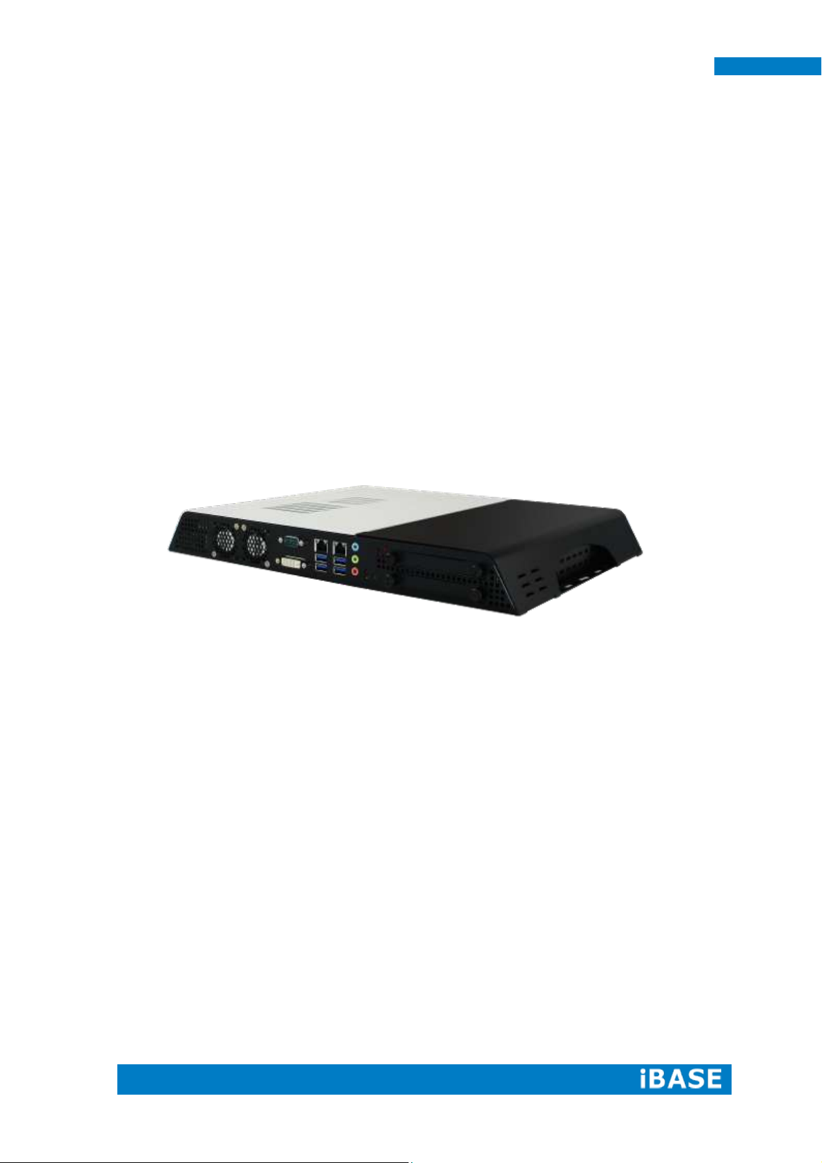
The “Signature Book™” SI-60E is a professional digital signage system powered
by 4th Gen. Intel® CoreTM I Desktop Processors with AMD Radeon™ E8860 graphics.
The SI-60E integrates 12 HDMI ports with EDID emulation function and one DVI-I for
console. Additionally, SI-60E has two quad-channel DDR3L-1600 sockets to provide
up to 32GB of memory. It also has dual Gigabit Ethernet, dual extended SSD drive,
Intel AMT for remote control and IBASE’s iSMART green technology for power on/off
scheduling and power resume functions. The ruggedized design player’s chassis that
provides passive cooling for better system reliability and quiet operation.
SI-60E overview
Page 10
2
SI-60E User Manual
Model Name
SI-60E
System Mainboard
MBD60E
CPU
4th Generation Intel® Core™ i7/i5/i3 and Pentium® QC/DC
processors; Up to 3.5GHz
Memory
4x DDR3 1600 MHz, Max. 32GB
I/O Interface
12x HDMI with EDID emulation function
1x DVI-I for console
4x USB 3.0 ports
2x RJ45 for LAN
1x RJ45 for RS232
3x Microjack audio connectors for Line-in / Line-out/MIC-in
Power LED for power on/off & HDD
1x power button
1x AC power inlet
Storage
1x mSATA
2x SATA 3.0 2.5” HDD Dock (support Raid 1)
Expansion Slots
Dual mPCI-E(x1) slots for WiFi, 3G/LTE, capture card and TV
tuner options
Construction
SGCC
Mounting
Standard system bracket
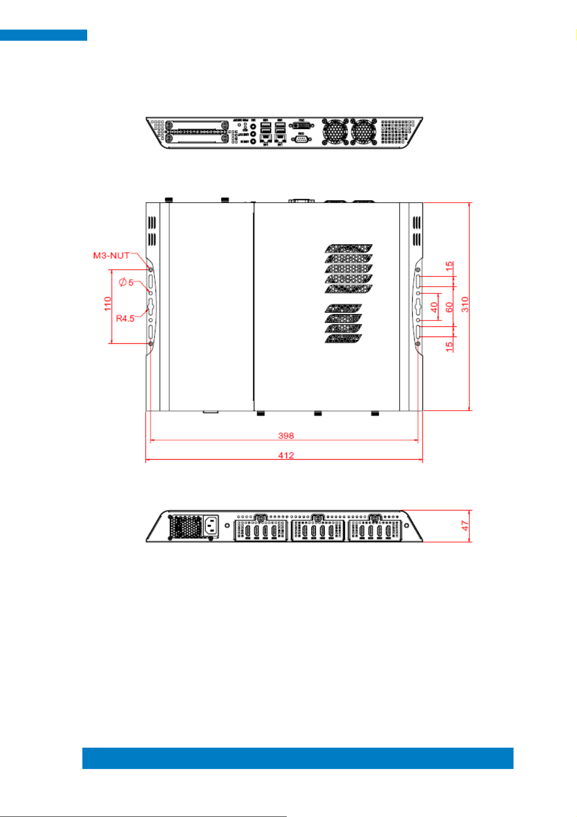
Dimensions
412mm(W) x 310mm(D) x 47mm(H)
16.22”(W) x 12.2”(D) x 1.85”(H)
Operating
Temperature
0°C~ 45°C (32°F~113°F)
Storage
Temperature
-20°C ~ 80°C (-4°F~176°F)
Relative Humidity
5~90% @ 45°C, (non-condensing)
Vibration
mSATA: 5 grms / 5~500Hz / random operation
RoHS
Available
Certification
CE, FCC, CCC, UL
1.2 System Specifications
1.2.1 Hardware Specifications
‧
This specification is subject to change without prior notice.
Page 11
Copyright © 2013 IBASE Technology Inc. All Rights Reserved.
3
IBASE Technology Inc.
1.2.2 Dimensions
Page 12
4
SI-60E User Manual
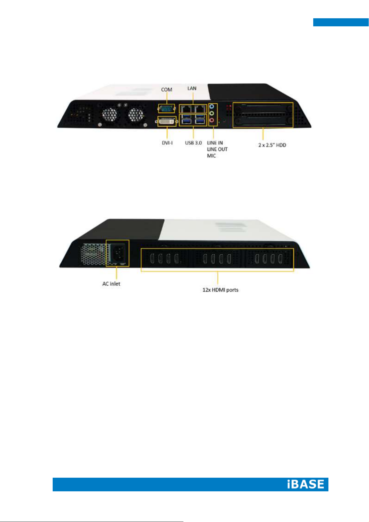
1.2.3 I/O View
SI-60E front side
SI-60E rear side
Page 13
Copyright © 2013 IBASE Technology Inc. All Rights Reserved.
5
IBASE Technology Inc.
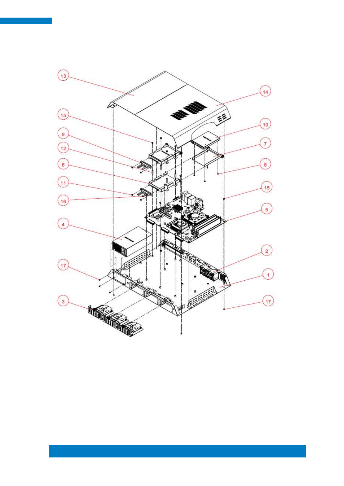
1.3 Exploded View of the SI-60E Assembly
Page 14
6
SI-60E User Manual
Part No.
Description
Part No.
Description
1
SI-60E_BASE
2
4028_fan
3
HDMI Board Module
4
Power module
5
SI-60E Main Board
6
SI-60E_HDD-TRAY
7
SI-60E_HDD-BRK
8
Screw F Type M3*0.5
9
SATA Cable
10
2.5" SATA HDD
11
M3 nut
12
M3 double screw bolt
13
SI-60E_top-cover_L
14
SI-60E_top-cover_r
15
Screw PW Type M3*0.5
16
M3 screw
17
Screw F Type M3*0.5 BK
1.3.1 Parts Description
Page 15
Copyright © 2013 IBASE Technology Inc. All Rights Reserved.
7
IBASE Technology Inc.
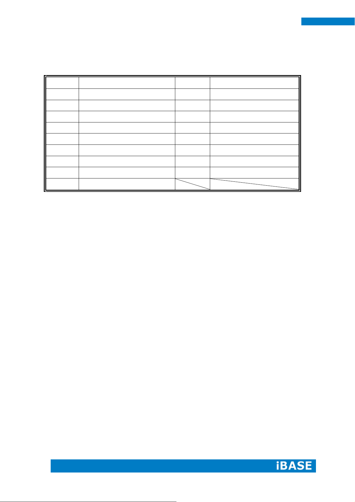
Item No.
Description
Qty
1
Driver CD
1 2 Power adaptor
1
3
Power cord
1
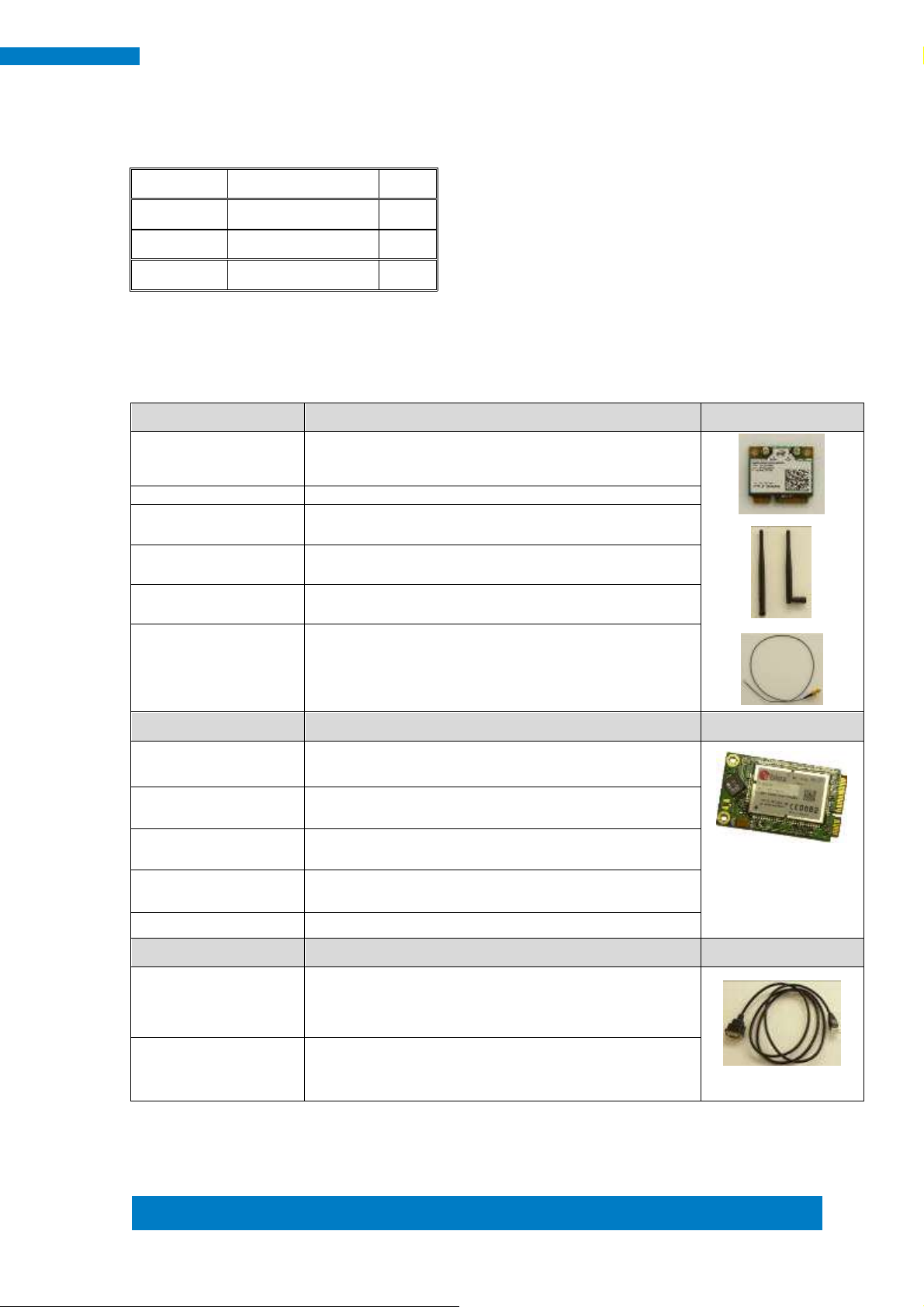
WiFi Solution
Description
WiFi module
Wireless; PCI-E Mini Card 802.11B/G/N [AW-NE238H]
(A008WLAWNE238H000P)
External Antenna 2pcs
WiFi Antenna (A055RFA02C2M20800P)
Internal cable 1pcs
Internal Antenna 300mm [BTC130-1-70B-300] RoHS
(A055RFA0000020100P)
Internal cable 1pcs
Internal Antenna 200mm [BTC130-1-70B-200-1] RoHS
(A055RFA0000020000P)
Screw, 2pcs
Screw; A44-N NI 3.4 NYLOK M2*L3.8 P0.4mm [LHS]
RoHS (H02203A0442200N00P)
Bracket, -1set
Component BOM; MPCIE-EXT V-B2 Bracket
(SC2MPCIEEXT0B2100P)
3G Solution
Description
3G
Wireless; 3.75G UMTS/HSPA [ZU202] RoHS
(A008WIRELESS00520P)
3G+GPS
Wireless; 3.75G UMTS/HSPA & GPS Module
[ZU200] RoHS (A008WIRELESS00510P)
WW-350U
Wireless; 3.75G UMTS/HSPA [NAVISYS WW-350U]
RoHS (A008WIRELESS00530P)
Cable
Cable; SMA IPX Cable For 3G 30CM [RF11030A]
RoHS (A012INTENAL010000P)
Antenna
3G [ANT0921Q2P] RoHS (A055ANT0921Q2P000P)
COM Port Cable
Description
EXT-311
Cable; EXT-311 2-HD 10C 150CM; DSUB-9F =>
RJ45-10M RoHS (C501EXT3110A12000P)
EXT-312
Cable; EXT-312 2-HD 10C 150CM; DSUB-9M =>
RJ45-10M RoHS (C501EXT3120A12000P)
1.4 Packing List
1.4.1 Optional Items module
Page 16
8
SI-60E User Manual
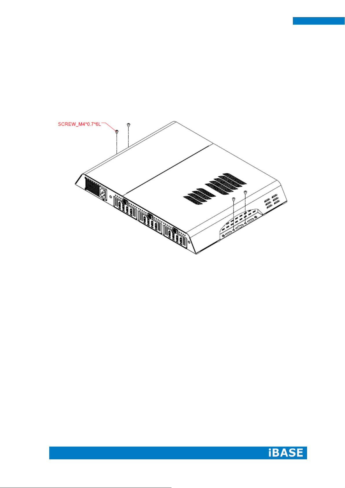
1.5 HARDWARE INSTALLATION
1.5.1 Mounting Installation
1. Please install SI-60E to the intended location using 4x M4*0.7*6L screws, as shown
in the picture.
Page 17
Copyright © 2013 IBASE Technology Inc. All Rights Reserved.
9
IBASE Technology Inc.
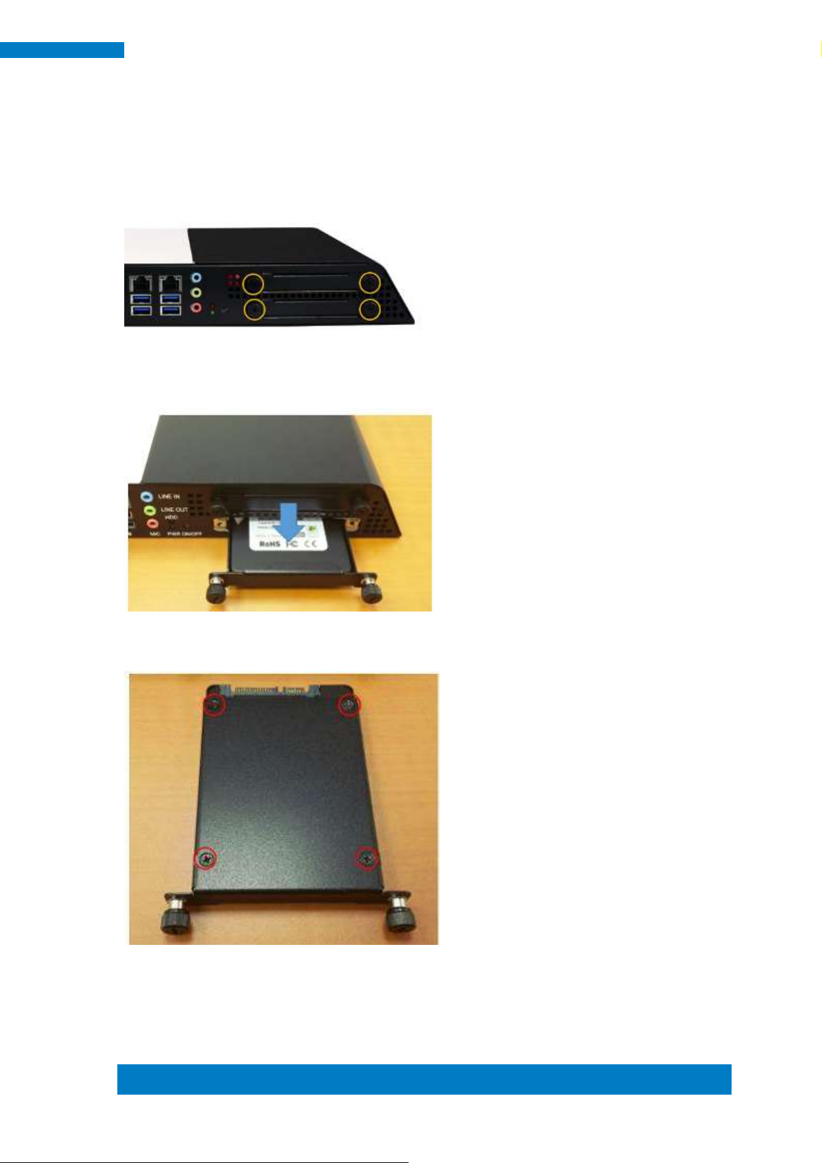
1.5.2 Installing the storage
1. Remove the two screws on the HDD cover and draw the HDD out.
2. Install the HDD/SSD to the HDD bracket with 4 screws.
Page 18
10
SI-60E User Manual
CHAPTER 2 MOTHERBOARD INTRODUCTION
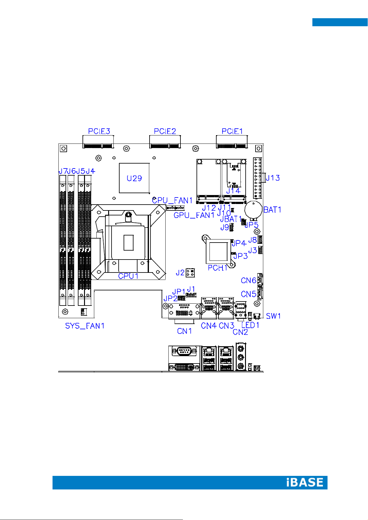
2.1 Introduction
MBD60E Jumpers and Connectors
Page 19
Copyright © 2013 IBASE Technology Inc. All Rights Reserved.
11
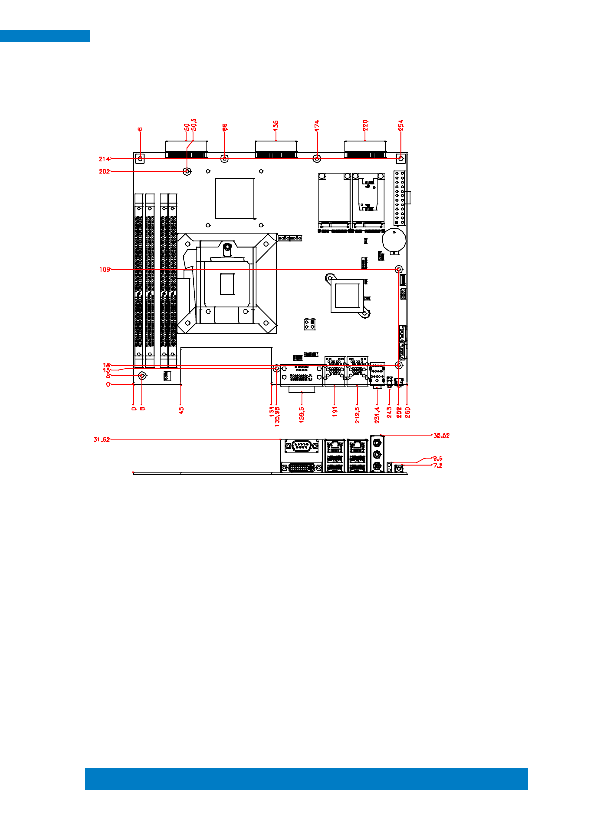
IBASE Technology Inc.
IMBD60E Board Dimensions
Page 20
12
SI-60E User Manual
2.2 Installations
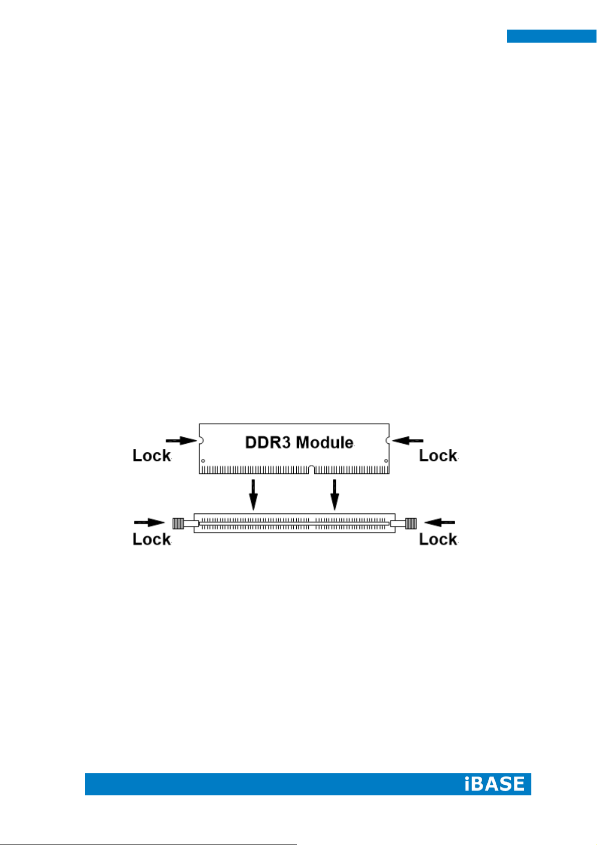
2.2.1 Installing the Memory
The MBD60E board supports four DDR3 memory modules for a maximum total of
32GB in DDR3 SODIMM memory type.
Installing and Removing Memory Modules
To install the DDR3 modules, locate the memory slot on the board and perform the
following steps:
1. Hold the DDR3 module so that the key of the DDR3 module aligned with that on the
memory slot.
2. Gently push the DDR3 module in an upright position until the clips of the slot close
to hold the DDR3 module in place when the DDR3 module touches the bottom of
the slot.
3. To remove the DDR3 module, press the clips with both hands.
Page 21
Copyright © 2013 IBASE Technology Inc. All Rights Reserved.
13
IBASE Technology Inc.
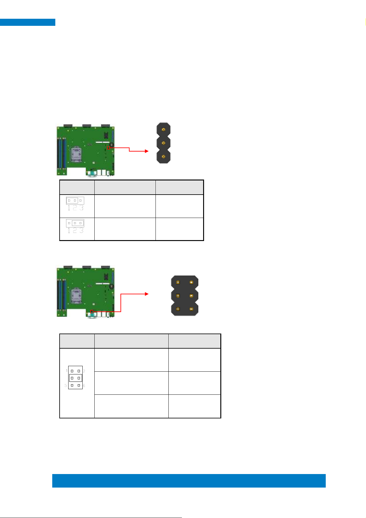
JBAT1
Setting
Function
Pin 1-2
Short/Closed
Normal
Pin 2-3
Short/Closed
Clear CMOS
JP1
Setting
Function
Pin 1-3
Short/Closed
+12V
Pin 3-4
Short/Closed
RI
Pin 5-3
Short/Closed
+5V
1
3
1 2
5 6
2.3 Setting the Jumpers
Jumpers are used on MBD60E to select various settings and features according to
your needs and applications. Contact your supplier if you have doubts about the best
configuration for your needs. The following lists the jumpers and connectors on
MBD60E and their respective functions.
JBAT1: Clear CMOS Contents
JP1: COM2 RS232 RI/+5V/+12V Power Setting
Page 22
14
SI-60E User Manual
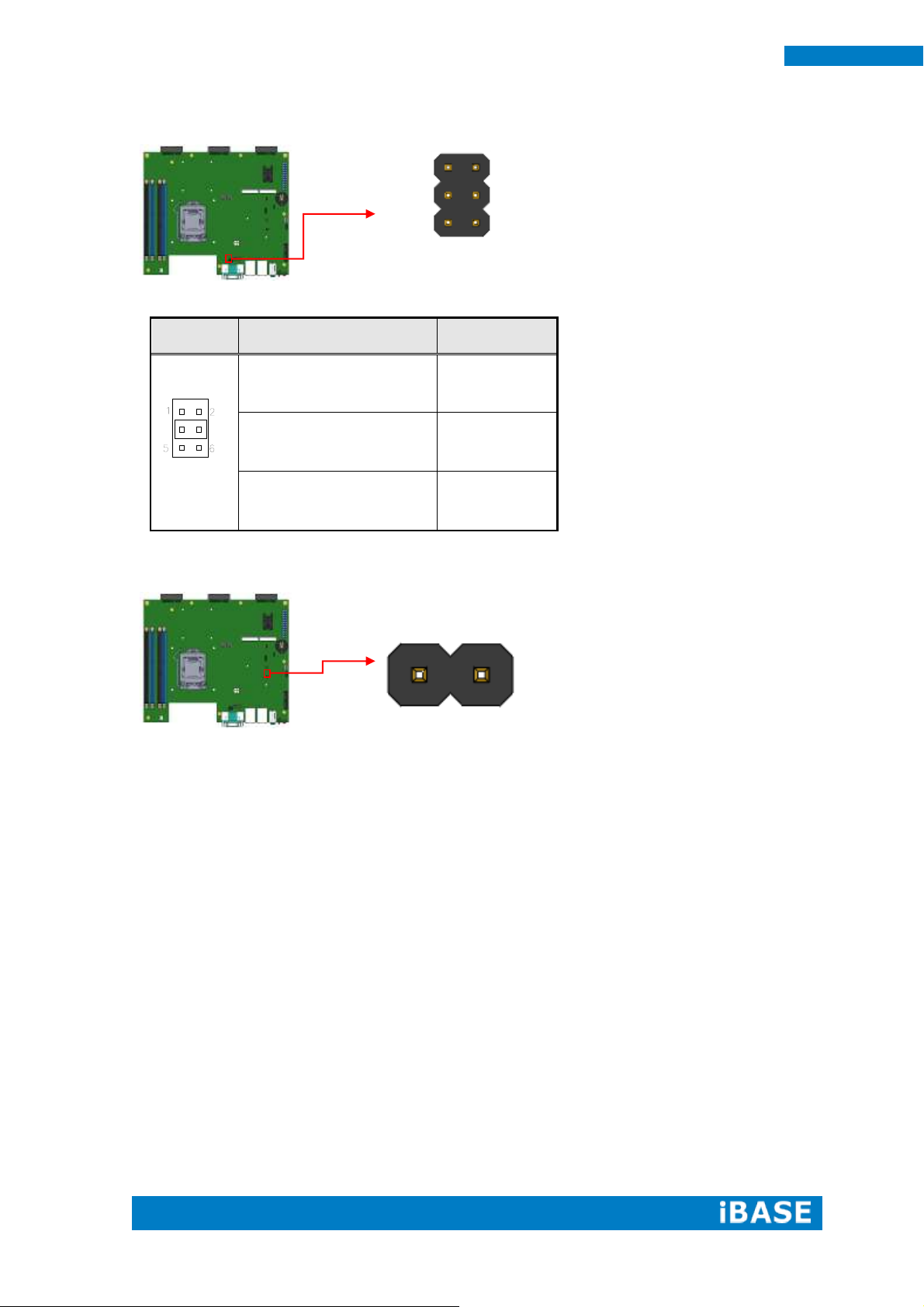
JP2
Setting
Function
Pin 1-3
Short/Closed
+12V
Pin 3-4
Short/Closed
RI
Pin 5-3
Short/Closed
+5V
2 1
1 2
5 6
JP2: COM1 RS232 RI/+5V/+12V Power Setting
JP3: Flash Descriptor Security Override (Factory use only)
Page 23
Copyright © 2013 IBASE Technology Inc. All Rights Reserved.
15
IBASE Technology Inc.
Signal Name
Pin #
Pin #
Signal Name
Data carrier detect
1
2
Receive data
Transmit data
3
4
Data terminal ready
Ground
5
6
Data set ready
Request to send
7
8
Clear to send
Ring indicator
9
10
Not Used
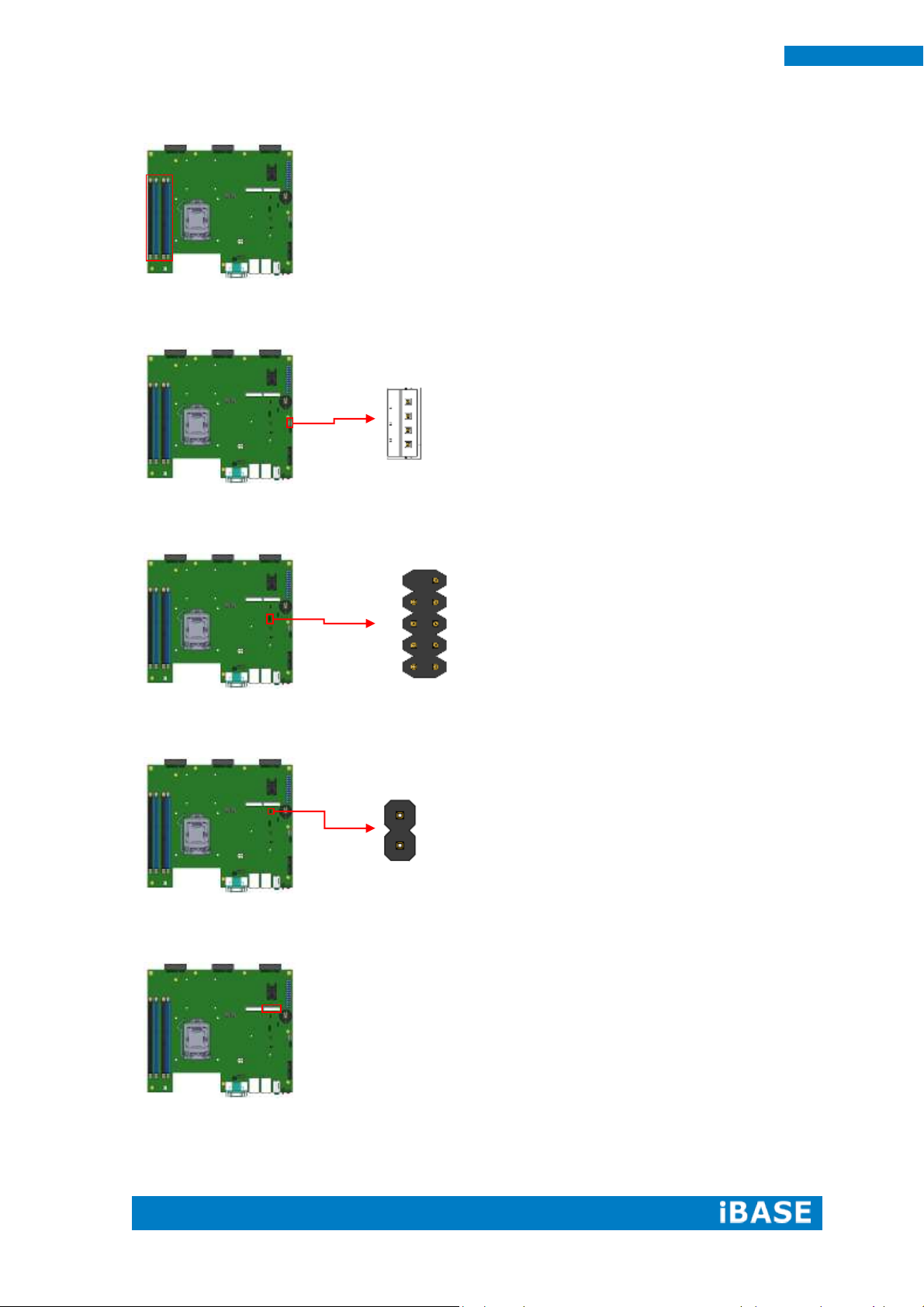
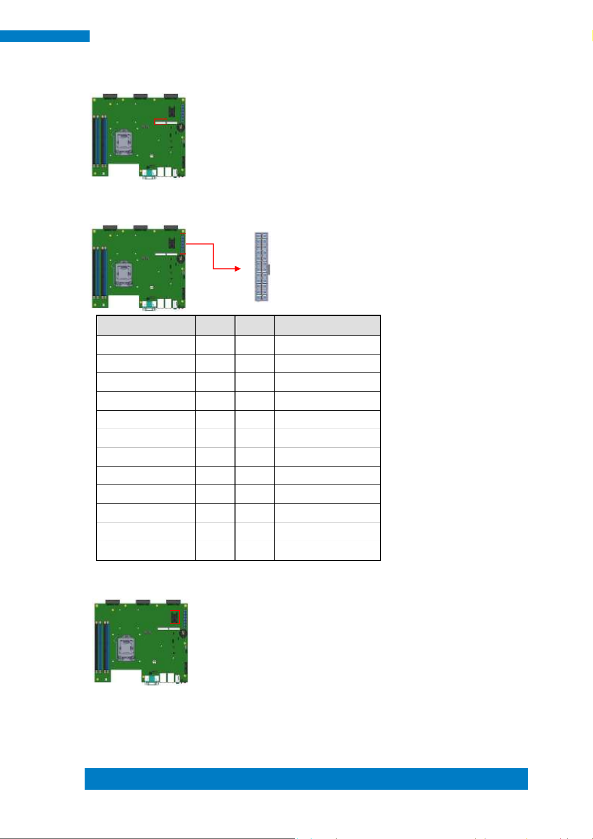
Pin #
Signal Name
1
Ground
2
Ground
3
DC_IN
4
DC_IN
1 9
2 10
3 1
4 2
1 2
9 10
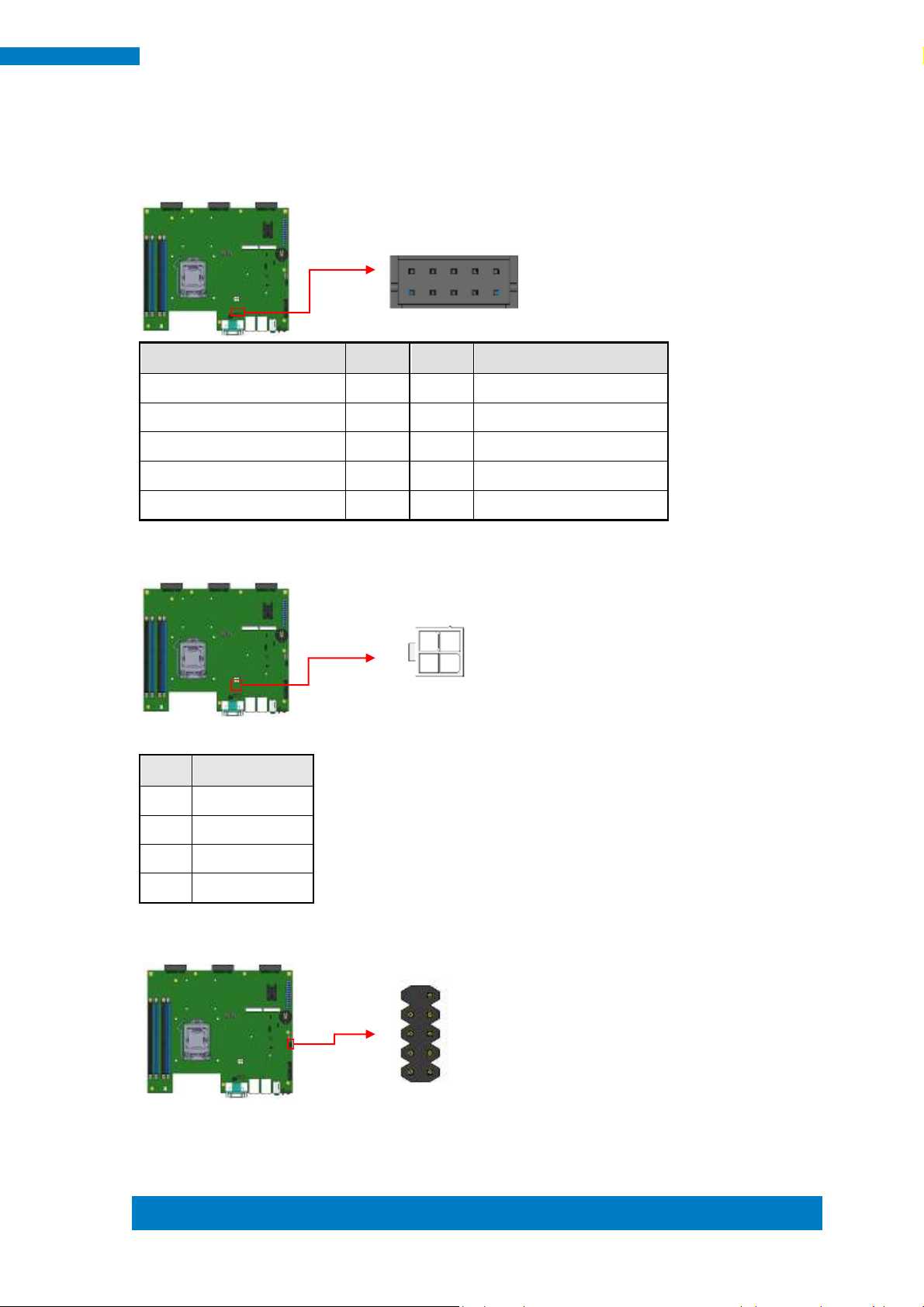
2.4 Connectors on MBD60E
J1: COM2 Connector [HRS DF11-10DP-2DSA(08)]
J2: ATX +12V Jack [HAOGUO ATX4PT-NY46]
J3: For SPI Debug tools Pin Header
Page 24
16
SI-60E User Manual
1
4
10 9
2 1
2
1
J4, J5, J6, J7 DDR III Socket
J8: MCU Flash Connector (factory use only)
J9: Debug Port Connector (Factory use only)
J10: Reset Pin Header
J11: Mini PCIe Slot (Full size with SIM Card)
Page 25
Copyright © 2013 IBASE Technology Inc. All Rights Reserved.
17
IBASE Technology Inc.
Signal Name
Pin #
Pin #
Signal Name
3.3V
13 1 3.3V
-12V
14 2 3.3V
Ground
15 3 Ground
PS-ON
16 4 +5V
Ground
17 5 Ground
Ground
18 6 +5V
Ground
19 7 Ground
-5V
20 8 Power good
+5V
21 9 5VSB
+5V
22
10
+12V
+5V
23
11
+12V
Ground
24
12
+3.3V
12 24
1 13
J12: Mini PCIe Slot (Full size with mSATA)
J13: ATX Power Supply Connector
J14: SIM Card Slot
Page 26
18
SI-60E User Manual
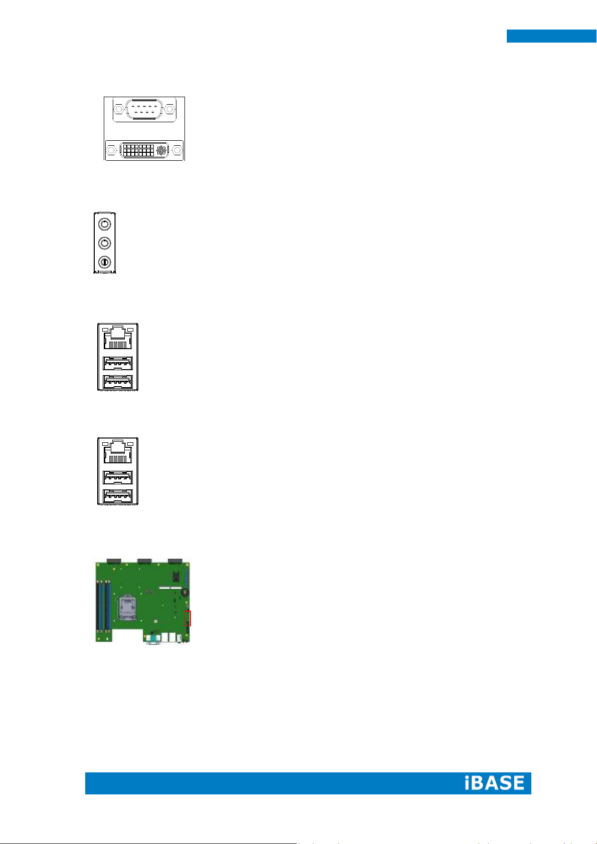
CN1: COM1 / DVI-I Connector
CN2: Audio Jack
CN3: RTL8111G-CG /USB3.0 Connector
CN4: I218LM / USB3.0 Connector
CN5/6:SATA 3 Connector
Page 27
Copyright © 2013 IBASE Technology Inc. All Rights Reserved.
19
IBASE Technology Inc.
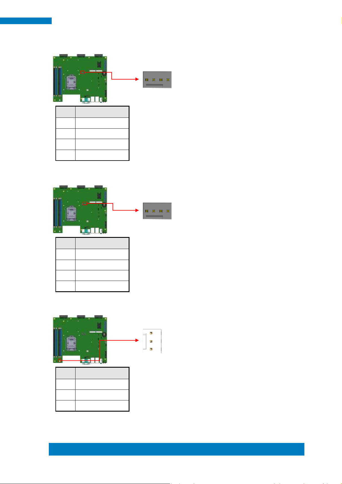
Pin #
Signal Name
1
Ground
2
+12V
3
Rotation detection
4
Control
Pin #
Signal Name
1
Ground
2
+12V
3
Rotation detection
4
Control
Pin #
Signal Name
1
Ground
2
+12V
3
Rotation detection
1 4
1
3
1 4
CPU_FAN1: CPU Fan Power Connector
GPU_FAN1: GPU Fan Power Connector
SYS_FAN1: System Fan1 Power Connector
Page 28
20
SI-60E User Manual
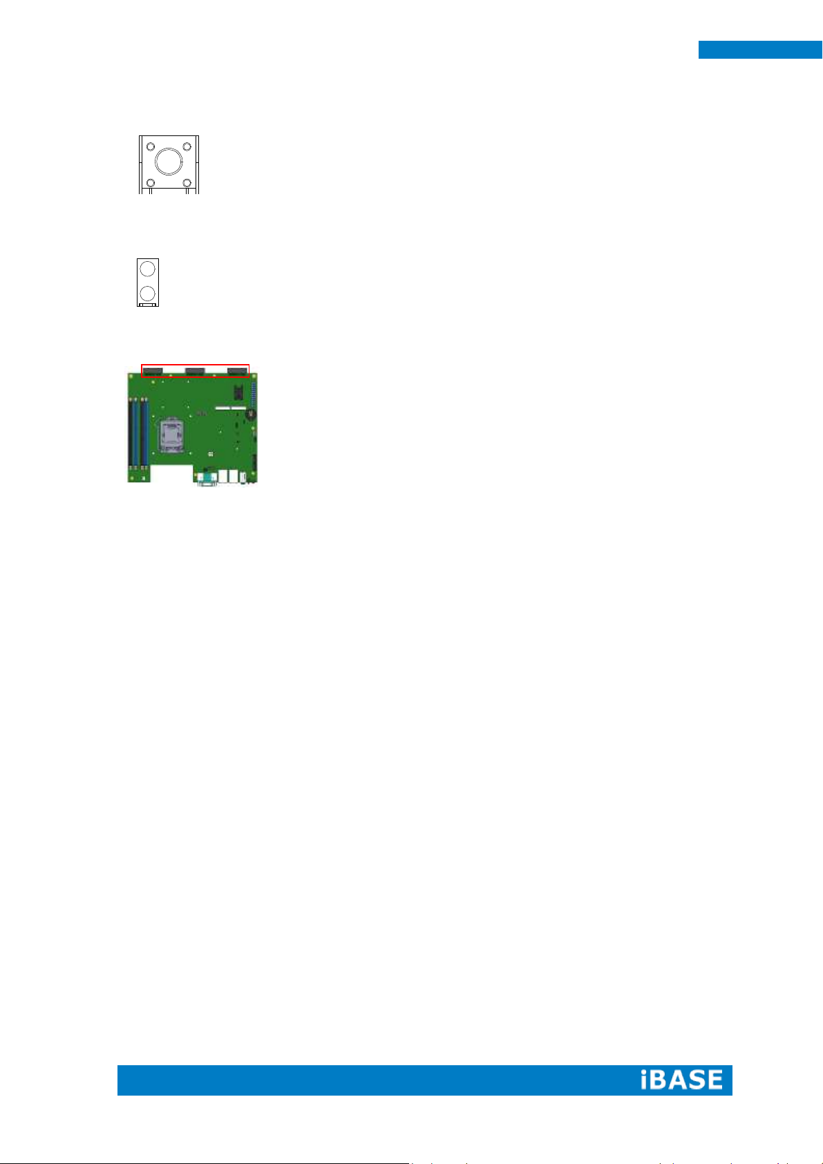
SW1: Power On Button
LED1: PWR (Green)/ HDD LED (Red)
PCIE1, PCIE2, PCIE3: DP Signal from AMD E8860 to IDD100
Page 29

Copyright © 2013 IBASE Technology Inc. All Rights Reserved.
21
IBASE Technology Inc.
Warning:
It is strongly recommended that you avoid making any changes to the
chipset defaults. These defaults have been carefully chosen by both
AMI and your system manufacturer to provide the absolute maximum
performance and reliability. Changing the defaults could cause the
system to become unstable and crash in some cases.
CHAPTER 3 BIOS SETUP
This chapter describes the different settings available in the AMI BIOS that comes
with the board. The topics covered in this chapter are as follows:
3.1 BIOS Introduction
The BIOS (Basic Input/Output System) installed in your computer system’s ROM
supports Intel processors. The BIOS provides critical low-level support for a standard
device such as disk drives, serial ports and parallel ports. It also password protection
as well as special support for detailed fine-tuning of the chipset controlling the entire
system.
3.2 BIOS Setup
The BIOS provides a Setup utility program for specifying the system configurations
and settings. The BIOS ROM of the system stores the Setup utility. When you turn on
the computer, the BIOS is immediately activated. Pressing the <Del> key immediately
allows you to enter the Setup utility. If you are a little bit late pressing the <Del> key,
POST (Power On Self Test) will continue with its test routines, thus preventing you
from invoking the Setup. If you still wish to enter Setup, restart the system by pressing
the ”Reset” button or simultaneously pressing the <Ctrl>, <Alt> and <Delete> keys.
You can also restart by turning the system Off and back On again. The following
message will appear on the screen:
Press <DEL> to Enter Setup
In general, you press the arrow keys to highlight items, <Enter> to select, the <PgUp>
and <PgDn> keys to change entries, <F1> for help and <Esc> to quit.
When you enter the Setup utility, the Main Menu screen will appear on the screen.
The Main Menu allows you to select from various setup functions and exit choices.
Page 30

22
SI-60E User Manual
Main Advanced Chipset Boot Security Save & Exit
System Language
[English]
→ ←Select Screen
↑↓Select Item
Enter: Select
+- Change Opt.
F1:General Help
F2:Previous Values
F3: Optimized Defaults
F4: Save & Exit
ESC: Exit
System Date
System Time
[Tue
01/20/2009]
[21:52:06]
Access Level
Administrator
Main Settings
Aptio Setup Utility – Copyright © 2012 American Megatrends, Inc.
System Language
Choose the system default language.
System Date
Set the Date. Use Tab to switch between Data elements.
System Time
Set the Time. Use Tab to switch between Data elements.
Page 31

Copyright © 2013 IBASE Technology Inc. All Rights Reserved.
23
IBASE Technology Inc.
Main Advanced Chipset Boot Security Save & Exit
► ACPI Settings
► Trusted Computing
→ ←Select Screen
↑↓Select Item
Enter: Select
+- Change Opt.
F1:General Help
F2:Previous Values
F3: Optimized Defaults
F4: Save & Exit
ESC: Exit
► Wake up event setting
► CPU Configuration
► SATA Configuration
►Shutdown Temperature Configuration
► iSmart Controller 3.1
► AMT Configuration
► USB Configuration
► F81846 Super IO Configuration
► F81846 H/W Monitor
Advanced Settings
This section allows you to configure and improve your system and allows you to set up some
system features according to your preference.
Aptio Setup Utility – Copyright © 2012 American Megatrends, Inc.
Page 32

24
SI-60E User Manual
Main Advanced Chipset Boot Security Save & Exit
ACPI Settings
→ ←Select Screen
↑↓Select Item
Enter: Select
+- Change Opt.
F1:General Help
F2:Previous Values
F3: Optimized Defaults
F4: Save & Exit
ESC: Exit
ACPI Sleep State
S3 only (Suspend to …)
Lock Legacy Resources
S3 Video Repost
Disabled
Disabled
ACPI Settings
Aptio Setup Utility – Copyright © 2012 American Megatrends, Inc.
ACPI Sleep State
Select ACPI sleep state the system will enter when the SUSPEND button is pressed.
Lock Legacy Resources
Enables or Disables Lock of Legacy Resources
S3 Video Repost
Enable or Disable S3 Video Repost
Page 33

Copyright © 2013 IBASE Technology Inc. All Rights Reserved.
25
IBASE Technology Inc.
Main Advanced Chipset Boot Security Save & Exit
Configuration
→ ←Select Screen
↑↓Select Item
Enter: Select
+- Change Opt.
F1:General Help
F2:Previous Values
F3: Optimized Defaults
F4: Save & Exit
ESC: Exit
Security Device Support
Disabled
Current Status Information
SUPPORT TURNED OFF
Trusted Computing
Aptio Setup Utility – Copyright © 2012 American Megatrends, Inc.
Security Device Support
Enables or disables BIOS support for security device. O.S. will not show Security Device.
TCG EFI protocol and INT1A interface will not be available.
TPM State
Enable/Disable Security Device. NOTE: Your Computer will reboot during restart in order to
change State of the Device.
Pending operation
Schedule an Operation for the Security Device. NOTE: Your Computer will reboot during
restart in order to change State of Security Device.
Page 34

26
SI-60E User Manual
Main Advanced Chipset Boot Security Save & Exit
→ ←Select Screen
↑↓Select Item
Enter: Select
+- Change Opt.
F1: General Help
F2: Previous Values
F3: Optimized Defaults
F4: Save & Exit
ESC: Exit
Wake on PCIE Wake Event
Disabled
Wake up event settings
Aptio Setup Utility – Copyright © 2012 American Megatrends, Inc.
Wake on PCIE Wake Event
The options are Disabled and Enabled.
Page 35

Copyright © 2013 IBASE Technology Inc. All Rights Reserved.
27
IBASE Technology Inc.
Main Advanced Chipset Boot Security Save & Exit
CPU Configuration
Intel(R) Core(TM) i7-4770S CPU @ 3.10GHz
→ ←Select Screen
↑↓Select Item
Enter: Select
+- Change Opt.
F1: General Help
F2: Previous Values
F3: Optimized Defaults
F4: Save & Exit
ESC: Exit
CPU Signature
306c3
Processor Family
6
Microcode Patch
17
FSB Speed
100 MHz
Max CPU Speed
3100 MHz
Min CPU Speed
800 MHz
CPU Speed
3500 MHz
Processor Cores
4
Intel HT Technology
Supported
Intel VT-x Technology
Supported
Intel SMX Technology
Supported
64-bit
Supported
EIST Technology
Supported
Hyper-threading
Enabled
Active Processor Cores
Overclocking lock
All
Disabled
Limit CPUID Maximum
Disabled
Execute Disable Bit
Disabled
Intel Virtualization Technology
Hardware Prefetcher
Disabled
Disabled
Adjacent Cache Line Prefetch
Disabled
EIST
Enabled
Turbo Mode
Enabled
CPU Configuration
This section shows the CPU configuration parameters.
Aptio Setup Utility – Copyright © 2012 American Megatrends, Inc.
Page 36

28
SI-60E User Manual
Hyper-threading
Enabled for Windows XP and Linux (OS optimized for Hyper-Threading Technology) and
Disabled for other OS (OS not optimized for Hyper-Threading Technology). When Disabled
only one thread per enabled core is enabled.
Active Processor Cores
Number of cores to enable in each processor package.
Overclocking lock
FLEX_RATIO(194) MSR
Limit CPUID Maximum
Disabled for Windows XP
Execute Disable Bit
XD can prevent certain classes of malicious buffer overflow attacks when combined with a
supporting OS (Windows Server 2003 SP1, Windows XP SP2, SuSE Linux 9.2, RedHat
Enterprise 3 Update 3.)
Intel Virtualization Technology
When enabled, a VMM can utilize the additional hardware capabilities provided by
Vanderpool Technology
Hardware Prefetcher
Enable the Mid Level Cache (L2) streamer prefetcher.
Adjacent Cache Line Prefetch
Enable the Mid Level Cache (L2) prefetching of adjacent cache lines.
EIST
Enable/Disable Intel Speedstep
Turbo Mode
Turbo Mode.
Page 37

Copyright © 2013 IBASE Technology Inc. All Rights Reserved.
29
IBASE Technology Inc.
Main Advanced Chipset Boot Security Save & Exit
SATA Controller(s)
Enabled
SATA Mode Selection
AHCI
SATA Controller Speed
Default
Serial ATA Port 0
Empty
Software Preserve
Unknown
Port 0
Enabled
Hot Plug
Disabled
Serial ATA Port 1
Empty
Software Preserve
Unknown
Port 1
Enabled
Hot Plug
Disabled
Serial ATA Port 2
Software Preserve
Port 2
Hot Plug
Serial ATA Port 3
Software Preserve
Port 3
Hot Plug
Serial ATA Port 4
Software Preserve
Port 4
Hot Plug
Serial ATA Port 5
Software Preserve
Port 5
Hot Plug
Empty
Unknown
Enabled
Disabled
Empty
Unknown
Enabled
Disabled
Empty
Unknown
Enabled
Disabled
Empty
Unknown
Enabled
Disabled
→ ←Select Screen
↑↓Select Item
Enter: Select
+- Change Opt.
F1:General Help
F2:Previous Values
F3: Optimized Defaults
F4: Save & Exit
ESC: Exit
SATA Configuration
Aptio Setup Utility – Copyright © 2012 American Megatrends, Inc.
SATA Controller(s)
Enable or disable SATA Device.
SATA Mode Selection
Determines how SATA controller(s) operate.
(1) IDE Mode.
(2) AHCI Mode.
(3) RAID Mode.
SATA Controller Speed
Indicates the maximum speed the SATA controller can support.
Port 0
Enable or Disable SATA Port
Hot Plug
Designates this port as Hot Pluggable.
Page 38

30
SI-60E User Manual
Main Advanced Chipset Boot Security Save & Exit
→ ←Select Screen
↑↓Select Item
Enter: Select
+- Change Opt.
F1:General Help
F2:Previous Values
F3: Optimized Defaults
F4: Save & Exit
ESC: Exit
APCI Shutdown Temperature
Disabled
Main Advanced Chipset Boot Security Save & Exit
iSmart Controller 3.1
→ ←Select Screen
↑↓Select Item
Enter: Select
+- Change Opt.
F1:General Help
F2:Previous Values
F3: Optimized Defaults
F4: Save & Exit
ESC: Exit
Power-On after Power failure
PWR Resume Delay
PWR Resume Delay Value(Seconds)
Temperature Guardian
Enable
Enable
5
Disable
Schedule Slot 1
None
Schedule Slot 2
None
Shutdown Temperature Configuration
Aptio Setup Utility – Copyright © 2012 American Megatrends, Inc.
ACPI Shutdown Temperature
The default setting is Disabled.
iSmart Controller 3.1
Aptio Setup Utility – Copyright © 2012 American Megatrends, Inc.
Power-On after Power failure
This field sets the system power status whether Disable or Enable when power returns to the
system from a power failure situation.
Temperature Guardian
Generate the reset signal when system hangs up on POST.
Schedule Slot 1 / 2
Setup the hour/minute for system power on.
Page 39

Copyright © 2013 IBASE Technology Inc. All Rights Reserved.
31
IBASE Technology Inc.
Main Advanced Chipset Boot Security Save & Exit
→ ←Select Screen
↑↓Select Item
Enter: Select
+- Change Opt.
F1:General Help
F2:Previous Values
F3: Optimized Defaults
F4: Save & Exit
ESC: Exit
Intel AMT
Enabled
BIOS Hotkey Pressed
Disabled
MEBx Selection Screen
Disabled
Hide Un-Configure ME Confirmation
Disabled
Un-Configure ME
Disabled
Amt Wait Timer
0
Activate Remote Assistance Process
Disabled
USB Configure
Enabled
PET Progress
Enabled
AMT CIRA Timeout
0
Watchdog
Disabled
OS Timer
0
BIOS Timer
0
AMT Configuration
Aptio Setup Utility – Copyright © 2012 American Megatrends, Inc.
Intel AMT
Enable/Disable Intel (R) Active Management Technology BIOS Extension.
Note: iAMT H/W is always enabled. This option just controls the BIOS extension execution.
If enabled, this requires additional firmware in the SPI device.
BIOS Hotkey Pressed
OEMFLag Bit 1:
Enable/Disable BIOS hotkey press.
AMT Configuration
OEMFLag Bit 2:
Enable/Disable MEBx selection screen.
Hide Un-Configure ME Configuration
OEMFlag Bit 6:
Hide Un-Configure ME without password Confirmation Prompt
Un-Configure ME
OEMFlag Bit 15:
Un-Configure ME without password.
Page 40

32
SI-60E User Manual
Main Advanced Chipset Boot Security Save & Exit
USB Configuration
→ ←Select Screen
↑↓Select Item
Enter: Select
+- Change Opt.
F1:General Help
F2:Previous Values
F3: Optimized Defaults
F4: Save & Exit
ESC: Exit
USB Module Version
8.10.28
USB Devices:
Legacy USB Support
Enabled
USB3.0 Support
Enabled
XHCI Hand-off
Enabled
EHCI Hand-off
Enabled
USB Mass Storage Driver Support
Enabled
USB hardware delays and time-outs:
USB Transfer time-out
20 sec
Device reset tine-out
20 sec
Device power-up delay
Auto
Amt Wait Timer
Set timer to wait before sending ASF_GET_BOOT_OPTIONS.
Activate Remote Assistance Process
Trigger CIRA boot.
USB Configure
Enable/Disable USB Configure function.
PET Progress
User can Enable/Disable PET Events progress to receive PET events or not.
Watchdog Timer
Enable/Disable Watchdog Timer.
USB Configuration
Aptio Setup Utility – Copyright © 2012 American Megatrends, Inc.
Page 41

Copyright © 2013 IBASE Technology Inc. All Rights Reserved.
33
IBASE Technology Inc.
Legacy USB Support
Enables Legacy USB support.
AUTO option disables legacy support if no USB devices are connected.
DISABLE option will keep USB devices available only for EFI applications.
USB3.0 Support
Enable/Disable USB3.0 (XHCI) Controller support.
XHCI Hand-off
This is a workaround for OSes without XHCI hand-off support. The XHCI ownership change
should be claimed by XHCI driver.
EHCI Hand-off
This is a workaround for OSes without EHCI hand-off support. The XHCI ownership change
should be claimed by EHCI driver.
USB Mass Storage Driver Support
Enable/Disable USB Mass Storage Driver Support.
USB Transfer time-out
The time-out value for Control, Bulk, and Interrupt transfers.
Device reset tine-out
USB mass Storage device start Unit command time-out.
Device power-up delay
Maximum time the device will take before it properly reports itself to the Host Controller.
‘Auto’ uses default value: for a Root port it is 100ms, for a Hub port the delay is taken from
Hub descriptor.
Page 42

34
SI-60E User Manual
Main Advanced Chipset Boot Security Save & Exit
F81846 Super IO Configuration
→ ←Select Screen
↑↓Select Item
Enter: Select
+- Change Opt.
F1:General Help
F2:Previous Values
F3: Optimized Defaults
F4: Save & Exit
ESC: Exit
F81846 Super IO Chip
F81846
► Serial Port 0 Configuration
► Serial Port 1 Configuration
F81846 Super IO Configuration
Aptio Setup Utility – Copyright © 2012 American Megatrends, Inc.
Serial Port Configuration
Set Parameters of Serial Ports. User can Enable/Disable the serial port and Select an optimal
settings for the Super IO Device.
Page 43

Copyright © 2013 IBASE Technology Inc. All Rights Reserved.
35
IBASE Technology Inc.
Main Advanced Chipset Boot Security Save & Exit
PC Health Status
→ ←Select Screen
↑↓Select Item
Enter: Select
+- Change Opt.
F1:General Help
F2:Previous Values
F3: Optimized Defaults
F4: Save & Exit
ESC: Exit
CPU temperature
+34 C
SYS temperature
+29 C
FAN1 Speed
2170 RPM
FAN2 Speed
2170 RPM
FAN3 Speed
2170 RPM
+5V
+5.087 V
+12V
+12.056 V
Fan 1 smart fan control
Fan 1 smart fan control
Fan 1 smart fan control
50 C
50 C
50 C
F81846 H/W Monitor
Aptio Setup Utility – Copyright © 2012 American Megatrends, Inc.
Temperatures/Voltages
These fields are the parameters of the hardware monitoring function feature of the
motherboard. The values are read-only values as monitored by the system and show the PC
health status.
Smart SYS_FAN1/CPU_FAN1 Function
This field enables or disables the smart fan feature.
Disabled (default)
50 ℃
60 ℃
70 ℃
80 ℃
Page 44

36
SI-60E User Manual
Main Advanced Chipset Boot Security Save & Exit
► PCH-IO Configuration
► System Agent (SA) Configuration
Main Advanced Chipset Boot Security Save & Exit
Intel PCH RC Version
1.8.0.0
→ ←Select Screen
↑↓Select Item
Enter: Select
+- Change Opt.
F1:General Help
F2:Previous Values
F3: Optimized Defaults
F4: Save & Exit
ESC: Exit
Intel PCH SKU Name
Q87
Intel PCH Rev ID
05/C2
► PCI Express Configuration
► USB Configuration
► PCH Azalia Configuration
PCH LAN Controller
Wake on LAN
Enabled
Enabled
Chipset Settings
This section allows you to configure and improve your system and allows you to set up some
system features according to your preference.
Aptio Setup Utility – Copyright © 2012 American Megatrends, Inc.
PCH-IO Configuration
This section allows you to configure the North Bridge Chipset.
Aptio Setup Utility – Copyright © 2012 American Megatrends, Inc.
PCH LAN Controller
Enable or disable onboard NIC.
Wake on LAN
Enable or disable integrated LAN to wake the system. (The Wake On LAN cannot be
disabled if ME is on at Sx state.)
Page 45

Copyright © 2013 IBASE Technology Inc. All Rights Reserved.
37
IBASE Technology Inc.
Main Advanced Chipset Boot Security Save & Exit
PCI Express Configuration
→ ←Select Screen
↑↓Select Item
Enter: Select
+- Change Opt.
F1:General Help
F2:Previous Values
F3: Optimized Defaults
F4: Save & Exit
ESC: Exit
DMI Link ASPM Control
Enabled
DMI Link Extended Synch Control
Disabled
PCIe-USB Glitch W/A
Disabled
Subtractive Decode
Disabled
► PCI Express Root Port 1
► PCI Express Root Port 2
► PCI Express Root Port 3
► PCI Express Root Port 4
► PCI Express Root Port 5
PCI-E Port 6 is assigned to LAN
► PCI Express Root Port 7
► PCI Express Root Port 8
PCI Express Configuration
Aptio Setup Utility – Copyright © 2012 American Megatrends, Inc.
DMI Link ASPM Control
The control of Active State Power Management on both NB side and SB side of the DMI
Link.
DMI Link Extended Synch Control
The control of Extended Synch on SB side of the DMI Link.
PCIe-USB Glitch W/A
PCIe-USB Glitch W/A for bad USB device(s) connected behind PCIE/PEG port.
Subtractive Decode
Enable or disable PCI Express Subtractive Decode.
Page 46

38
SI-60E User Manual
Main Advanced Chipset Boot Security Save & Exit
USB Configuration
→ ←Select Screen
↑↓Select Item
Enter: Select
+- Change Opt.
F1:General Help
F2:Previous Values
F3: Optimized Defaults
F4: Save & Exit
ESC: Exit
USB Precondition
Disabled
xHCI Mode
Auto
USB Ports Per-Port Disable Control
Disabled
Main Advanced Chipset Boot Security Save & Exit
PCH Azalia Configuration
Azalia
Auto
USB Configuration
USB Precondition
Precondition work on USB host controller and root ports for faster enumeration.
xHCI Mode
Mode of operation of xHCI controller.
USB Ports Per-Port Disable Control
Control each of the USB ports (0~13) disabling.
PCH Azalia Configuration
Aptio Setup Utility – Copyright © 2012 American Megatrends, Inc.
Azalia
Control Detection of the Azalia device.
Disabled = Azalia will be unconditionally disabled.
Enabled Azalia will be unconditionally Enabled.
Auto = Azalia will be enabled if present, disabled otherwise.
Page 47

Copyright © 2013 IBASE Technology Inc. All Rights Reserved.
39
IBASE Technology Inc.
Main Advanced Chipset Boot Security Save & Exit
System Agent Bridge Name Haswell
→ ←Select Screen
↑↓Select Item
Enter: Select
+- Change Opt.
F1:General Help
F2:Previous Values
F3: Optimized Defaults
F4: Save & Exit
ESC: Exit
System Agent RC Version
1.8.0.0
VT-d Capability
Supported
VT-d
Enabled
► Graphics Configuration
► Memory Configuration
Main Advanced Chipset Boot Security Save & Exit
Graphics Configuration
→ ←Select Screen
↑↓Select Item
Enter: Select
+- Change Opt.
F1:General Help
F2:Previous Values
F3: Optimized Defaults
F4: Save & Exit
ESC: Exit
Primary Display
Primary PEG
Primary PCIE
PEG
Auto
Auto
Internal Graphics
Disabled
System Agent (SA) Configuration
Aptio Setup Utility – Copyright © 2012 American Megatrends, Inc.
VT-d
Check to enable VT-d function on MCH.
Graphics Configuration
Aptio Setup Utility – Copyright © 2012 American Megatrends, Inc.
Page 48

40
SI-60E User Manual
Main Advanced Chipset Boot Security Save & Exit
Memory Information
→ ←Select Screen
↑↓Select Item
Enter: Select
+- Change Opt.
F1:General Help
F2:Previous Values
F3: Optimized Defaults
F4: Save & Exit
ESC: Exit
Memory RC Version
1.8.0.0
Memory Frequency
1600 MHz
Total Memory
Memory Voltage
32768MB (DDR3)
1.50V
DIMM#0
8192 MB (DDR3)
DIMM#1
8192 MB (DDR3)
DIMM#2
8192 MB (DDR3)
DIMM#3
8192 MB (DDR3)
Primary Display
Select which of IGFX/PEG/PCI graphics device should be Primary Display or select SG for
switchable Gfx.
Primary PEG
Select PEG0/PEG1/PEG2/PEG3 Graphics device should be Primary PEG.
Primary PCIE
Select PCIE0/PCIE1/PCIE2/PCIE3/PCIE4/PCIE5/PCIE6PCIE7 Graphics device should be
Primary PCIE.
Internal Graphics
Keep IGD enabled based on the setup options.
Memory Configuration
Aptio Setup Utility
Page 49

Copyright © 2013 IBASE Technology Inc. All Rights Reserved.
41
IBASE Technology Inc.
Main Advanced Chipset Boot Security Save & Exit
Boot Configuration
→ ←Select Screen
↑↓Select Item
Enter: Select
+- Change Opt.
F1:General Help
F2:Previous Values
F3: Optimized Defaults
F4: Save & Exit
ESC: Exit
Setup Prompt Timeout
1
Bootup NumLock State
On
Quiet Boot
Disabled
Fast Boot
Boot Mode select
Disabled
LEGACY
FIXED BOOT ORDER Priorities
Boot Option #1
Hard Disk
Boot Option #2
Boot Option #3
Boot Option #4
Boot Option #5
Boot Option #6
Boot Option #7
CD/DVD
USB Hard Disk
USB CD/DVD
USB Key
USB Floppy
Network
► CSM16 parameters
CSM parameters
Boot Settings
This section allows you to configure the boot settings.
Aptio Setup Utility – Copyright © 2012 American Megatrends, Inc.
Setup Prompt Timeout
Number of seconds to wait for setup activation key.
65535(0xFFFF) means indefinite waiting.
Bootup NumLock State
Select the keyboard NumLock state
Quiet Boot
Enables or disables Quiet Boot option
Fast Boot
Enables or disables boot with initialization of a minimal set of devices required to launch
active boot option. Has no effect for BBS boot options.
Boot Mode select
Select boot mode LEGACY/UEFI
Page 50

42
SI-60E User Manual
Main Advanced Chipset Boot Security Save & Exit
→ ←Select Screen
↑↓Select Item
Enter: Select
+- Change Opt.
F1:General Help
F2:Previous Values
F3: Optimized Defaults
F4: Save & Exit
ESC: Exit
Launch CSM
Enabled
Boot option filter
UEFI and Legacy
Launch PXE OpROM policy
Do not launch
Launch Storage OpROM policy
Legacy only
Launch Video OpROM policy
Legacy only
Other PCI device ROM priority
Legacy OpROM
FIXED BOOT ORDER Priorities
Sets the system boot order
CSM parameters
This section allows you to configure the boot settings.
Aptio Setup Utility – Copyright © 2012 American Megatrends, Inc.
Launch CSM
This option controls if CSM will be launched
Boot option filter
This option controls what devices system can boot to
Launch PXE OpROM policy
Controls the execution of UEFI and Legacy PXE OpROM
Launch Storatge OpROM policy
Controls the execution of UEFI and Legacy Storage OpROM
Launch Video OpROM policy
Controls the execution of UEFI and Legacy Video OpROM
Other PCI device ROM priority
For PCI devices other than Network, Mass storage or Video defines which OpROM to launch
Page 51

Copyright © 2013 IBASE Technology Inc. All Rights Reserved.
43
IBASE Technology Inc.
Main Advanced Chipset Boot Security Save & Exit
Password Description
→ ←Select Screen
↑↓Select Item
Enter: Select
+- Change Opt.
F1:General Help
F2:Previous Values
F3: Optimized Defaults
F4: Save & Exit
ESC: Exit
If ONLY the Administrator’s password is set,
then this only limit access to Setup and is
only asked for when entering Setup.
If ONLY the User’s password is set, then this
is a power on password and must be entered to boot
or enter Setup. In Setup the User will
have Administrator rights.
The password length must be
in the following range:
Minimum length
3
Maximum length
20
Administrator Password
User Password
Security Settings
This section allows you to configure and improve your system and allows you to set up some system
features according to your preference.
Aptio Setup Utility – Copyright © 2012 American Megatrends, Inc.
Administrator Password
Set Administrator Password
User Password
Set User Password
Page 52

44
SI-60E User Manual
Main Advanced Chipset Boot Security Save & Exit
Save Changes and Exit
→ ←Select Screen
↑↓Select Item
Enter: Select
+- Change Opt.
F1:General Help
F2:Previous Values
F3: Optimized Defaults
F4: Save & Exit
ESC: Exit
Discard Changes and Exit
Save Changes and Reset
Discard Changes and Reset
Save Options
Save Changes
Discard Changes
Restore Defaults
Save as User Defaults
Restore User Defaults
Save & Exit Settings
Aptio Setup Utility – Copyright © 2012 American Megatrends, Inc.
Save Changes and Exit
Exit system setup after saving the changes.
Discard Changes and Exit
Exit system setup without saving any changes.
Save Changes and Reset
Reset the system after saving the changes.
Discard Changes and Reset
Reset system setup without saving any changes.
Save Changes
Save Changes done so far to any of the setup options.
Discard Changes
Discard Changes done so far to any of the setup options.
Restore Defaults
Restore/Load Defaults values for all the setup options.
Save as User Defaults
Save the changes done so far as User Defaults.
Restore User Defaults
Restore the User Defaults to all the setup options.
Page 53

Copyright © 2013 IBASE Technology Inc. All Rights Reserved.
45
IBASE Technology Inc.
CHAPTER 4 DRIVERS INSTALLATION
The Intel Chipset Drivers should be installed first before the software drivers to
enable Plug & Play INF support for Intel chipset components. Follow the instructions
below to complete the installation.
IMPORTANT NOTE:
After installing your Windows operating system, you must install first the Intel Chipset Software
Installation Utility before proceeding with the drivers installation.
4.1 Intel Chipset Software Installation Utility
1. Insert the DVD that comes with the board. Click System and then SI-60E Series
Products.
2. Click Intel(R) Chipset Software Installation Utility.
Page 54

46
SI-60E User Manual
3. When the Welcome screen to the Intel® Chipset Device Software appears, click
Next to continue.
4. Click Accept to accept the software license agreement and proceed with the
installation process.
Page 55

Copyright © 2013 IBASE Technology Inc. All Rights Reserved.
47
IBASE Technology Inc.
5. On the Readme File Information screen, click Install to continue the installation.
6. The Setup process is now complete. Click Finish to restart the computer and for
changes to take effect.
Page 56

48
SI-60E User Manual
4.2 AMD Radeon E8860 Graphics Driver
1. Insert the DVD that comes with the board. Click System and then SI-60E Series
Products. Click AMD Radeon E8860 Graphics Driver.
2. When the Welcome screen appears, click Next to continue.
3. Select the language you would like to be displayed and click Next.
Page 57

Copyright © 2013 IBASE Technology Inc. All Rights Reserved.
49
IBASE Technology Inc.
4. Click Install to continue the installation process.
Page 58

50
SI-60E User Manual
5. Select Express and the installation location and click Next.
6. Click Accept to accept the End User License Agreement.
Page 59

Copyright © 2013 IBASE Technology Inc. All Rights Reserved.
51
IBASE Technology Inc.
7. Setup complete. Click Finish to restart the computer and for changes to take effect.
8. To reboot the system, click Yes.
Page 60

52
SI-60E User Manual
4.3 Realtek High Definition Audio Driver
1. Insert the DVD that comes with the board. Click System and then SI-60E Series
Products.
2. Click Realtek High Definition Audio Driver.
Page 61

Copyright © 2013 IBASE Technology Inc. All Rights Reserved.
53
IBASE Technology Inc.
3. On the Welcome to the InstallShield Wizard screen, click Yes to proceed with and
complete the installation process.
4. The InstallShield Wizard Complete. Click Finish to restart the computer and for
changes to take effect.
Page 62

54
SI-60E User Manual
4.4 Intel® I21x Gigabit Network Driver
1. Insert the DVD that comes with the board. Click System and then SI -60E Series
Products.
2. Click Intel® I21x Gigabit Network Driver.
Page 63

Copyright © 2013 IBASE Technology Inc. All Rights Reserved.
55
IBASE Technology Inc.
3. When the Welcome screen appears, click Next.
4. Click Next to to agree with the license agreement.
Page 64

56
SI-60E User Manual
5. Click the checkbox for Drivers in the Setup Options screen to select it and click
Next to continue.
6. The wizard is ready to begin installation. Click Install to begin the installation.
Page 65

Copyright © 2013 IBASE Technology Inc. All Rights Reserved.
57
IBASE Technology Inc.
7. When InstallShield Wizard is complete, click Finish.
Page 66

58
SI-60E User Manual
4.5 Intel® Management Engine(ME) Driver
Follow the steps below to install the Intel Management Engine.
1. Insert the DVD that comes with the board. Click System and then SI-60E Series
Products.and then Intel® Management Engine(ME) Driver.
2. When the Welcome screen for Intel® Management Engine Components, click the
checkbox for Install Intel® Control Center & click Next.
Page 67

Copyright © 2013 IBASE Technology Inc. All Rights Reserved.
59
IBASE Technology Inc.
3. Click Yes to to agree with the license agreement.
4. When the Setup Progress screen appears, click Next. Then, click Finish when the
setup progress has been successfully installed.
Page 68

60
SI-60E User Manual
Page 69

Copyright © 2013 IBASE Technology Inc. All Rights Reserved.
61
IBASE Technology Inc.
4.6 Intel® USB 3.0 eXtensible Host Controller Driver
1. Insert the DVD that comes with the board. Click System and then SI-60E Series
Products. Click Intel® USB 3.0 eXtensible Host Controller Driver.
2. When the Welcome screen to the InstallShield Wizard for Intel® USB 3.0 eXtensible
Host Controller Driver, click Next.
Page 70

62
SI-60E User Manual
3. Click Yes to to agree with the license agreement and continue the installation.
4. On the Readme File Information screen, click Next to continue the installation of
the Intel® USB 3.0 eXtensible Host Controller Driver.
Page 71

Copyright © 2013 IBASE Technology Inc. All Rights Reserved.
63
IBASE Technology Inc.
5. Setup complete. Click Finish to restart the computer and for changes to take effect.
Page 72

64
SI-60E User Manual
4.7 Realtek RTL8111G LAN Driver
1. Insert the DVD that comes with the board. Click System and then SI-60E Series
Products. Click Realtek RTL8111G LAN Driver.
2. In the Welcome screen, click Next.
Page 73

Copyright © 2013 IBASE Technology Inc. All Rights Reserved.
65
IBASE Technology Inc.
3. When the Ready to Install the Program screen appears, click Install to continue.
4. When InstallShield Wizard is complete, click Finish.
Page 74

66
SI-60E User Manual
4.8 IDD100 Driver and Utility
1.Insert the DVD that comes with the board. Click System and then SI-60E Series
Products. Click IDD100 Driver and Utility.
2. Click CP210x Installer
Page 75

Copyright © 2013 IBASE Technology Inc. All Rights Reserved.
67
IBASE Technology Inc.
3. In the Welcome screen, click Next.
4. When the License Agreement the Program screen appears, click I accept this
agreement and Next.
Page 76

68
SI-60E User Manual
5.When complete the Installation of the CP210x USB to UART Bridge Driver, click Finish.
6.Click SI-60E Installer.
Page 77

Copyright © 2013 IBASE Technology Inc. All Rights Reserved.
69
IBASE Technology Inc.
7. In the Welcome screen, click Next.
8. When the Destination Folder screen appears, click Next.
Page 78

70
SI-60E User Manual
9. When the Ready to Install the Program screen appears, click Install.
10.When InstallShield Wizard Complete, click Finish.
Page 79

Copyright © 2013 IBASE Technology Inc. All Rights Reserved.
71
IBASE Technology Inc.
Appendix
A. IBASE Display Matrix User Manual
Software UART Control Application interface
Function Description
1. Device List: Max support up to 6 Box
2. Auto Loop Pattern (Button/Hot Key)
3. RGBW Pattern (Button/Hot Key)
4. HW RESET (Button/Hot Key)
5. MODE Clone/1x2/1x4/2x2
6. Support CLK SYNC
7. Support 60Hz/120Hz Modes
8. Support Multi-Box ID
9. Support Multi-Box Device Setting
10. Support H and V Bezel Adjustment
11. H Blanking Setting
12. V Blanking Setting
13. Apply Key
14. Program On/Off
Page 80

72
SI-60E User Manual
Stretch (1x2)
Stretch (1x4)
Stretch (2x2)
Clone
3840x1200
7680x1200
3840x2400
1920x1200
3840x1080
7680x1080
3840x2160
1920x1080
3360x1050
6720x1050
3360x2100
1680x1050
3200x1200
6400x1200
3200x2400
1600x1200
3200x0900
6400x0900
3200x1800
1600x0900
2880x1050
5760x1050
2880x2160
1440x1050
2880x0900
5760x0900
2880x1800
1440x0900
2800x1050
5600x1050
2800x2100
1400x1050
2732x0768
5464x0768
2732x1536
1366x0768
2560x1024
5120x1024
2560x2048
1280x1024
2560x0800
5120x0800
2560x1600
1280x0800
2560x0768
5120x0768
2560x1536
1280x0768
2560x0720
5120x0720
2560x1440
1280x0720
2048x0768
4096x0768
2048x1536
1024x0768
H Limit
V Limit
50
15
100
30
150
45
200
60
250
TBD
Display Mode Table
Bezel Limit with Blanking Parameter Table
How to Setting Clone Display
Step 1: Enter to Display Control Page
Step 2: Go to Mode Status Press Enter
Step 3: Press Up / Down Key Select to Clone
Step 4: Go to UP PORT to select a Display Mode
Step 5: Go to Display Driver Control Page
Step 6: Setting the two Monitor to Duplicate Mode
Page 81

Copyright © 2013 IBASE Technology Inc. All Rights Reserved.
73
IBASE Technology Inc.
How to Setting 1x4 Display
Step 1: Enter to Display Control Page
Step 2: Go to Mode Status Press Enter
Step 3: Press Up / Down Key Select to Stretch
Step 4: Go to Display Layout to Select 1x4
Step 5: Go to UP or DOWN Port select a Display Resolution
Step 6: Go to Display Driver Control Page
Step 7: Setting the two Monitor to H Combine Condition
Step 8: Adjustment H Bezel
How to Setting 2x2 Display
Step 1: Enter to Display Control Page
Step 2: Go to Mode Status Press Enter
Step 3: Press Up / Down Key Select to Stretch
Step 4: Go to Display Layout to Select 2x2
Step 5: Go to UP or DOWN Port select a Display Resolution
Step 6: Go to Display Driver Control Page
Step 7: Setting the two Monitor to V Combine Condition
Step 8: Adjustment H Bezel Value
Step 9: Adjustment V Bezel Value
Page 82

74
SI-60E User Manual
B. IBASE Multiple-Display Matrix Technology Utility for 4 x 3 Video Wall
Display configuration setting
1.1 What is ATI Eyefinity Technology?
ATI Eyefinity Technology from AMD provides advanced multiple monitor technology
delivering an incredibly immersive graphic and computing experience with innovative
display capabilities, supporting massive desktop workspaces and super-high
resolution signage applications. ATI Eyefinity technology with SI-58 6 X HDMI
connectivity enables a single GPU to support up to six independent display outputs
simultaneously. For the purposes of this document an “ATI Eyefinity system” means a
computer system employing ATI Eyefinity technology and an “ATI Eyefinity resolution”
means a resolution achievable using ATI Eyefinity technology.
Page 83

Copyright © 2013 IBASE Technology Inc. All Rights Reserved.
75
IBASE Technology Inc.
1.2 Product Description
IBASE offers user-friendly and powerful video solution in the form of SI-60E
(Signature Book) with IBASE Multiple-Display Matrix Technology Utility & AMD
Eyefinity function. Each IBASE SI-60E (Signature Book) with IBASE Multiple-Display
Matrix Technology Utility & Eyefinity function can drive up to 12 displays with different
display configuration.
Page 84

76
SI-60E User Manual
1.3 Driver Installation
Before using SI-60E (Signature Book)’s IBASE Multiple-Display Matrix Technology
Utility & AMD Eyefinity function, the user must install both SI-60EInstaller V 1.0 for
(CP210xVCPInstaller/ SI-60EControlCenter) and AMD VGA driver completely.
1.4 IBASE Multiple-Display Matrix Technology Utility
Click SI-60E Icon on the Desktop, to have Software UART Control
Application interface as shown:
Page 85

Copyright © 2013 IBASE Technology Inc. All Rights Reserved.
77
IBASE Technology Inc.
“Turn on” Device List
Page 86

78
SI-60E User Manual
On the above Device List item, please confirm and check each IDD 100 Device with
the different ID. If the Device has the same ID (the above two Device with the same ID
2), please select and click one of the same ID device, then select “Set DeviceID”
function to change its ID number, and click “Apply” to finish the setting.
Each IDD100 Device supports 4x HDMI output, and maximum resolution is 1920 X
1200 per HDMI. You have to check the display resolution first, then choose the
suitable resolution accordingly.
Page 87

Copyright © 2013 IBASE Technology Inc. All Rights Reserved.
79
IBASE Technology Inc.
The following is an example for FHD displays. Choose “Mode” as Stretch 2x2 and
“DP1” resolution is 3840 X 2160 (IDD100 Device with 4 x HDMI output as 2 x 2
combination mode).
Please choose “Clock Sync” as DP1 and enable “Device Setting Sync”, then click
“Apply”.
3 x IDD100 Device (Each with 4 x HDMI) will have the same setting at the same time.
Remarks: The reason we let 3 x IDD100 device “Clock Sync” to be the same as DP1
is because it can avoid differences in SYS GPU signal output to reduce tearing issues,
as well as keeps the SYS signal output stable.
Page 88

80
SI-60E User Manual
Now you can leave IBASE SI-60E control center V1.0 utility, and start using “AMD
Catalyst Control Center”
Page 89

Copyright © 2013 IBASE Technology Inc. All Rights Reserved.
81
IBASE Technology Inc.
Choose “AMD Eyefinity Multi-Display” for Video wall display configuration setting.
Page 90

82
SI-60E User Manual
Select “Create Euefinity Display Group”
Page 91

Copyright © 2013 IBASE Technology Inc. All Rights Reserved.
83
IBASE Technology Inc.
Select “2 x 3” for 4 x 3 Display configuration
Page 92

84
SI-60E User Manual
Make the displays arrangement
Page 93

Copyright © 2013 IBASE Technology Inc. All Rights Reserved.
85
IBASE Technology Inc.
Complete the settings.
Page 94

86
SI-60E User Manual
Now, you can use Screen resolution to check your setting.
A screen with 7680 X 3240 is the correct setting for 4 x 3 Display configuration with
FHD (1920 X 1080) resolution supported displays.
Page 95

Copyright © 2013 IBASE Technology Inc. All Rights Reserved.
87
IBASE Technology Inc.
Remark:
8 and 12 Displays configurations
Page 96

88
SI-60E User Manual
Address
Device Description
0000h-001Fh
Direct memory access controller
0000h-0CF7h
PCI bus
0040h-0043h
System timer
0050h-0053h
System timer
0070h-0077h
System CMOS/real time clock
0081h-0091h
Direct memory access controller
0093h-009Fh
Direct memory access controller
00C0h-00DFh
Direct memory access controller
00F0h-00F0h
Numeric data processor
02F8h-02FFh
Communications Port (COM2)
03B0h-03BBh
AMD Radeon E8860
03C0h-03DFh
AMD Radeon E8860
03F8h-03FFh
Communications Port (COM1)
0D00h-FFFFh
PCI bus
D000h-DFFFh
Intel(R) 8 Series/C220 Series PCI Express Root Port #7 - 8C1C
E000h-E0FFh
AMD Radeon E8860
F040h-F05Fh
Intel(R) 8 Series/C220 Series SMBus Controller - 8C22
F060h-F07Fh
Intel(R) 8 Series/C220 Series SATA AHCI Controller - 8C02
F0A0h-F0A3h
Intel(R) 8 Series/C220 Series SATA AHCI Controller - 8C02
F0B0h-F0B7h
Intel(R) 8 Series/C220 Series SATA AHCI Controller - 8C02
F0C0h-F0C3h
Intel(R) 8 Series/C220 Series SATA AHCI Controller - 8C02
F0D0h-F0D7h
Intel(R) 8 Series/C220 Series SATA AHCI Controller - 8C02
F0E0h-F0E7h
Intel(R) Active Management Technology - SOL (COM3)
C. I/O Port Address Map
Each peripheral device in the system is assigned a set of I/O port addresses which
also becomes the identity of the device. The following table lists the I/O port
addresses used.
Page 97

Copyright © 2013 IBASE Technology Inc. All Rights Reserved.
89
IBASE Technology Inc.
Level
Function
IRQ0
System Timer
IRQ3
Serial Port #2
IRQ4
Serial Port #1
IRQ 5
Intel(R) 8 Series/C220 Series SMBus Controller - 8C22
IRQ 13
Numeric data processor
IRQ 16
High Definition Audio Controller
IRQ 16
Intel(R) 8 Series/C220 Series USB EHCI #2 - 8C2D
IRQ 19
Intel(R) 8 Series/C220 Series SATA AHCI Controller - 8C02
IRQ 19
Intel(R) Active Management Technology - SOL (COM3)
IRQ 22
High Definition Audio Controller
IRQ 23
Intel(R) 8 Series/C220 Series USB EHCI #1 - 8C26
D. Interrupt Request Lines (IRQ)
Peripheral devices use interrupt request lines to notify CPU for the service required.
The following table shows the IRQ used by the devices on board.
Page 98

90
SI-60E User Manual
E. Watchdog Timer Configuration
The WDT is used to generate a variety of output signals after a user programmable count. The WDT is
suitable for use in the prevention of system lock-up, such as when software becomes trapped in a
deadlock. Under these sorts of circumstances, the timer will count to zero and the selected outputs will
be driven. Under normal circumstance, the user will restart the WDT at regular intervals before the
timer counts to zero.
SAMPLE CODE:
//--------------------------------------------------------------------------//
// THIS CODE AND INFORMATION IS PROVIDED "AS IS" WITHOUT WARRANTY OF ANY
// KIND, EITHER EXPRESSED OR IMPLIED, INCLUDING BUT NOT LIMITED TO THE
// IMPLIED WARRANTIES OF MERCHANTABILITY AND/OR FITNESS FOR A PARTICULAR
// PURPOSE.
//
//--------------------------------------------------------------------------#include <dos.h>
#include <conio.h>
#include <stdio.h>
#include <stdlib.h>
#include "F81846.H"
//--------------------------------------------------------------------------int main (int argc, char *argv[]);
void EnableWDT(int);
void DisableWDT(void);
//--------------------------------------------------------------------------int main (int argc, char *argv[])
{
unsigned char bBuf;
unsigned char bTime;
char **endptr;
char SIO;
printf("Fintek 81866 watch dog program\n");
SIO = Init_F81846();
if (SIO == 0)
{
printf("Can not detect Fintek 81866, program abort.\n");
return(1);
}//if (SIO == 0)
if (argc != 2)
{
printf(" Parameter incorrect!!\n");
return (1);
}
bTime = strtol (argv[1], endptr, 10);
printf("System will reset after %d seconds\n", bTime);
if (bTime)
{ EnableWDT(bTime);
}
else
{ DisableWDT();
}
return 0;
Page 99

Copyright © 2013 IBASE Technology Inc. All Rights Reserved.
91
IBASE Technology Inc.
}
//--------------------------------------------------------------------------void EnableWDT(int interval)
{
unsigned char bBuf;
bBuf = Get_F81846_Reg(0x2B);
bBuf &= (~0x20);
Set_F81846_Reg(0x2B, bBuf);
//Enable WDTO
Set_F81846_LD(0x07);
//switch to logic device 7
Set_F81846_Reg(0x30, 0x01);
//enable timer
bBuf = Get_F81846_Reg(0xF5);
bBuf &= (~0x0F);
bBuf |= 0x52;
Set_F81846_Reg(0xF5, bBuf);
//count mode is second
Set_F81846_Reg(0xF6, interval);
//set timer
bBuf = Get_F81846_Reg(0xFA);
bBuf |= 0x01;
Set_F81846_Reg(0xFA, bBuf);
//enable WDTO output
bBuf = Get_F81846_Reg(0xF5);
bBuf |= 0x20;
Set_F81846_Reg(0xF5, bBuf);
//start counting
}
//--------------------------------------------------------------------------void DisableWDT(void)
{
unsigned char bBuf;
Set_F81846_LD(0x07);
Page 100

92
SI-60E User Manual
//switch to logic device 7
bBuf = Get_F81846_Reg(0xFA);
bBuf &= ~0x01;
Set_F81846_Reg(0xFA, bBuf);
//disable WDTO output
bBuf = Get_F81846_Reg(0xF5);
bBuf &= ~0x20;
bBuf |= 0x40;
Set_F81846_Reg(0xF5, bBuf);
//disable WDT
}
//---------------------------------------------------------------------------
 Loading...