

Page 1

SI-304 User Manual
User Manual
SI-304
Page 2

ii
SI-304 User Manual
Revision
Release Date
V1.0
2015/07/30
Page 3

Copyright © 2013 IBASE Technology Inc. All Rights
Reserved.
iii
IBASE Technology Inc.
Copyright © 2013 IBASE Technology Inc. All Rights Reserved.
No part of this manual, including the products and software described in it, may be
reproduced, transmitted, transcribed, stored in a retrieval system, or translated into
any language in any form or by any means, except documentation kept by the
purchaser for backup purposes, without the express written permission of IBASE
Technology INC. (“IBASE ”).
Products and corporate names mentioned in this manual may or may not be
registered trademarks or copyrights of their respective companies, and are used for
identification purposes only. All trademarks are the property of their respective
owners.
Every effort has been made to ensure that the contents of this manual are correct
and up to date. However, the manufacturer makes no guarantee regarding the
accuracy of its contents, and reserves the right to make changes without prior notice.
Page 4

iv
SI-304 User Manual
Table of Contents
Setting up your system .......................................................................................................... v
Care during use ..................................................................................................................... vi
Acknowledgments ................................................................................................................ vii
CHAPTER 1 INTRODUCTION .................................................................................... 1
1.1 General Description.......................................................................................................... 1
1.2 System Specifications...................................................................................................... 2
1.2.1 Hardware Specifications ............................................................................................... 2
1.2.2 Dimensions .................................................................................................................... 3
1.2.3 I/O View ........................................................................................................................... 4
1.3 Exploded View of the SI-304 Assembly .......................................................................... 4
1.3.1 Parts Description ........................................................................................................... 5
1.4 Packing List ...................................................................................................................... 6
1.4.1 Optional Items module .................................................................................................. 6
1.5 Hardware Installation ....................................................................................................... 7
1.5.1 Mounting Installation..................................................................................................... 7
CHAPTER 2 MOTHERBOARD INTRODUCTION .......................................................... 8
2.1 Introduction....................................................................................................................... 8
2.2 Installations..................................................................................................................... 10
2.2.1 Installing the Memory .................................................................................................. 10
2.3 Setting the Jumpers ....................................................................................................... 11
CHAPTER 3 BIOS SETUP .........................................................................................14
3.1 BIOS Introduction ........................................................................................................... 14
3.2 BIOS Setup ...................................................................................................................... 14
CHAPTER 4 DRIVERS INSTALLATION .......................................................................33
4.1 VGA Drivers Installation ................................................................................................. 33
7. Click Accept to accept the End User License Agreement............................................. 36
4.2 Audio Drivers Installation .............................................................................................. 37
4.3 LAN Drivers Installation ................................................................................................. 38
Appendix ...............................................................................................................39
A. ATI Eyefinitity setting ....................................................................................................... 39
C. Interrupt Request Lines (IRQ) ......................................................................................... 47
D. Watchdog Timer Configuration ....................................................................................... 48
Page 5

Copyright © 2013 IBASE Technology Inc. All Rights
Reserved.
v
IBASE Technology Inc.
Safety Information
Your SI-304 is designed and tested to meet the latest standards of safety for
information technology equipment. However, to ensure your safety, it is important that
you read the following safety instructions
Setting up your system
Read and follow all instructions in the documentation before you operate your
system.
Do not use this product near water.
Set up the system on a stable surface. Do not secure the system on any
unstable plane.
Do not place this product on an unstable cart, stand, or table. The product may
fall, causing serious damage to the product.
Slots and openings on the chassis are for ventilation. Do not block or cover
these openings. Make sure you leave plenty of space around the system for
ventilation. Never insert objects of any kind into the ventilation openings.
This system should be operated from the type of power indicated on the
marking label. If you are not sure of the type of power available, consult your
dealer or local power company.
Use this product in environments with ambient temperatures between -10˚C and
60˚C.
If you use an extension cord, make sure that the total ampere rating of the
devices plugged into the extension cord does not exceed its ampere rating.
DO NOT LEAVE THIS EQUIPMENT IN AN ENVIRONMENT WHERE THE
STORAGE TEMPERATURE MAY GO BELOW -20° C (-4° F) OR ABOVE 80° C
(167° F). THIS COULD DAMAGE THE EQUIPMENT. THE EQUIPMENT
SHOULD BE IN A CONTROLLED ENVIRONMENT.
Page 6

vi
SI-304 User Manual
Care during use
Do not walk on the power cord or allow anything to rest on it.
Do not spill water or any other liquids on your system.
When the system is turned off, a small amount of electrical current still flows.
Always unplug all power, and network cables from the power outlets before
cleaning the system.
If you encounter the following technical problems with the product, unplug the
power cord and contact a qualified service technician or your retailer.
The power cord or plug is damaged.
Liquid has been spilled into the system.
The system does not function properly even if you follow the operating
instructions.
The system was dropped or the cabinet is damaged.
Lithium-Ion Battery Warning
CAUTION: Danger of explosion if battery is incorrectly replaced. Replace only with
the same or equivalent type recommended by the manufacturer. Dispose of used
batteries according to the manufacturer’s instructions.
NO DISASSEMBLY
The warranty does not apply to the products that have been disassembled by users
WARNING
HAZARDOUS MOVING PARTS
KEEP FINGERS AND OTHER BODY PARTS AWAY
Page 7

Copyright © 2013 IBASE Technology Inc. All Rights
Reserved.
vii
IBASE Technology Inc.
Acknowledgments
AMI is a registered trademark of AMI Software International, Inc.
AMD and ATI are registered trademarks of AMD Corporation.
Intel, Pentium, and Intel Core are registered trademarks or trademarks of
Intel Corporation.
Microsoft Windows is a registered trademark of Microsoft Corporation.
FINTEK is a registered trademark of FINTEK Electronics Corporation.
REALTEK is a registered trademark of REALTEK Electronics
Corporation.
All other product names or trademarks are properties of their respective
owners.
Page 8

Page 9
1
SI-304 User Manual
CHAPTER 1 INTRODUCTION
1.1 General Description
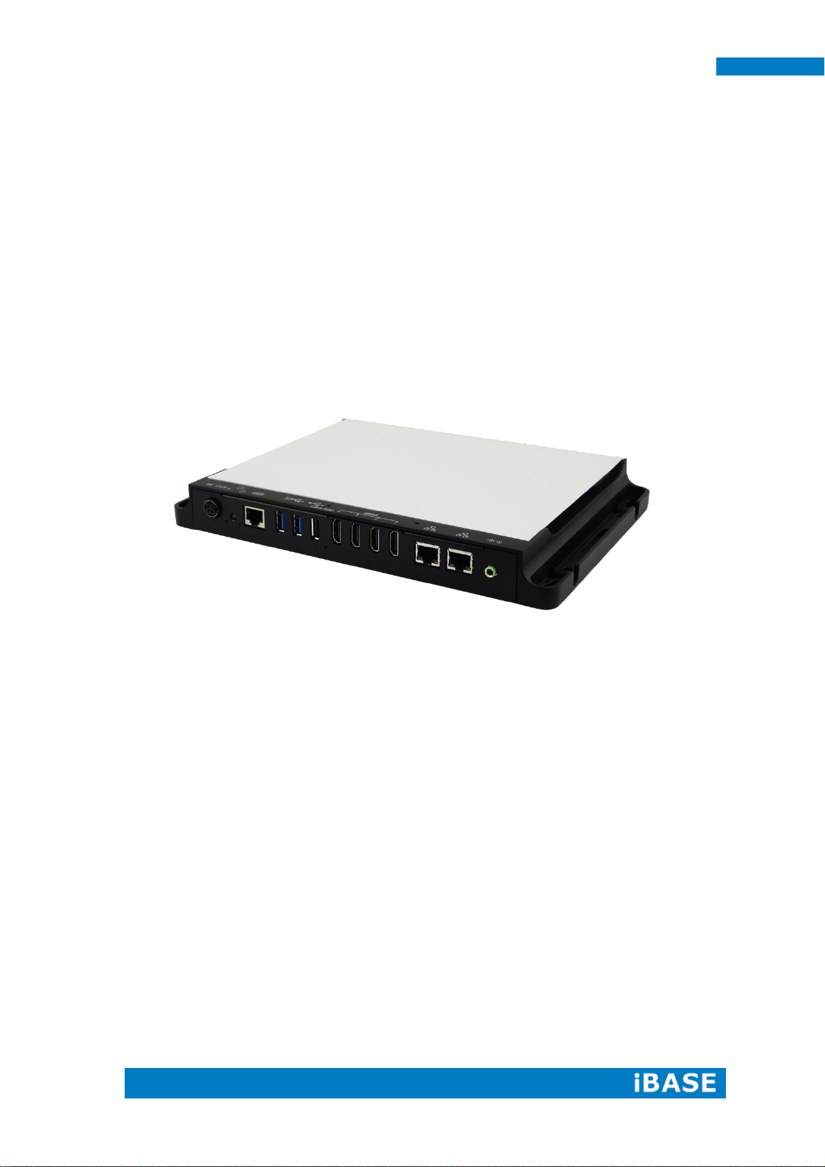
The “Signature Book™” SI-304 is a professional digital signage system powered
by 2nd Gen AMD Embedded R-series APU-based Signage Player with Radeon
9000 series graphics. The SI-304 integrates 4 HDMI ports with EDID emulation
function. Additionally, SI-304 has two dual-channel DDR3-2133 sockets to provide up
to 32GB of memory. It also has dual Gigabit Ethernet, one mSATA and NGFF drive
and IBASE’s iSMART green technology for power on/off scheduling and power resume
functions. The ruggedized design player’s chassis provides passive cooling for better
system reliability and quiet operation.
TM
HD
SI-304 overview
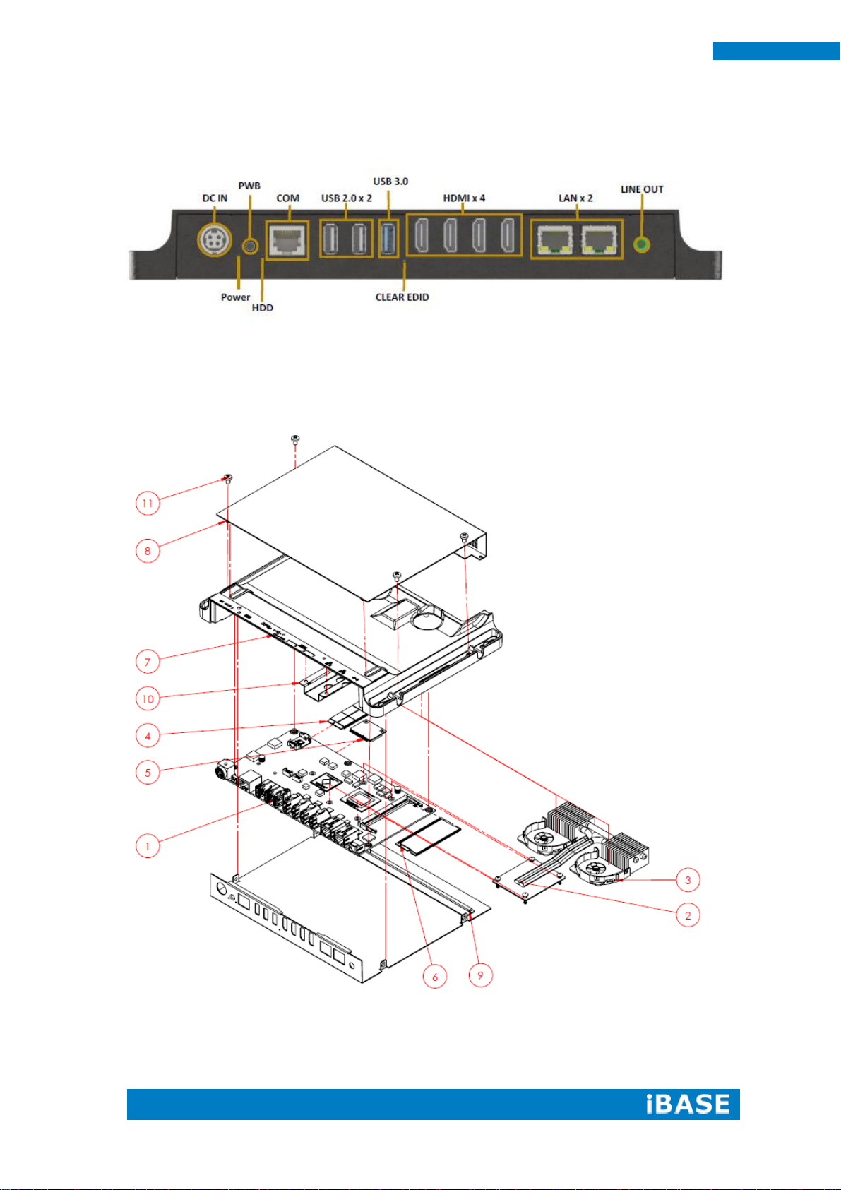
** The integrated four HDMI interface has built-in EDID emulation function. To use
the EDID function, turn off the power first. Then, connect the new display port. After
you turn on the power, SI-304 will detect new EDID data.
Page 10

2
SI-304 User Manual
Model Name
SI-304
System Mainboard
MBD304
CPU
2nd Gen. R-series QC RX-427BB 2.7/3.4G
DC RX-225BB 2.2/3.0G APU
Memory
2x DDR3 2133 SO-DIMM, dual channel, Max. 32GB
I/O Interface
4x HDMI
2x USB 3.0 ports
1x USB 2.0 port
2x RJ45 for LAN
1x RJ45 for RS232
1x Microjack audio connector for Line-in
Power LED / HDD LED, power on/off button
1x DC power jack
Storage
1x mSATA
1x NGFF M key 22 x 80mm(2280)
Expansion Slots
2x mPCIe(x1) for WiFi + Bluetooth, 3G, GPS and TV tuner options
1x UIM/SIM card slot (for 3G/LTE adaptor in mPCIe slot)
Construction
Aluminum + SGCC
Mounting
Slim design with wall mounting holes
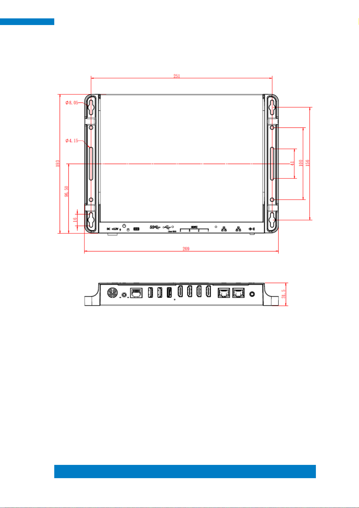
Dimensions
269mm(W) x 193mm(D) x 29.5mm(H)
10.59”(W) x 7.6”(D) x 1.16”(H)
Operating
Temperature
0°C~ 45°C (32°F~113°F)
Storage
Temperature
-20°C ~ 80°C (-4°F~176°F)
Relative Humidity
5~90% @ 45°C, (non-condensing)
Vibration
SSD: 5 grms / 5~500Hz / random operation
HDD: 0.25 grms / 5~500Hz / random operation
RoHS
Available
Certification
CE, FCC, CCC, UL
1.2 System Specifications
1.2.1 Hardware Specifications
‧
This specification is subject to change without prior notice.
Page 11
Copyright © 2013 IBASE Technology Inc. All Rights
Reserved.
3
IBASE Technology Inc.
1.2.2 Dimensions
Page 12
4
SI-304 User Manual
1.2.3 I/O View
SI-304 front side
1.3 Exploded View of the SI-304 Assembly
Page 13

Copyright © 2013 IBASE Technology Inc. All Rights
Reserved.
5
IBASE Technology Inc.
Part No.
Description
Part No.
Description
1
SI-304 Main Board
2
Thermal Module
3
System Fan
4
M.2 Module
5
Mini PCI-E
6
RAM
7
Die Casting-Case
8
Cover
9
I/O Plate
10
M.2 Bracket
11
Mounting Screw
1.3.1 Parts Description
Page 14
6
SI-304 User Manual
Item No.
Description
Qty
1
Driver CD
1 2 Power adaptor
1
3
Power cord
1
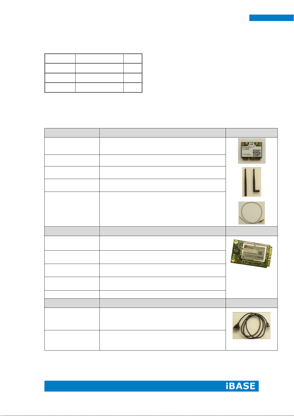
WiFi Solution
Description
WiFi module
Wireless; PCI-E Mini Card 802.11B/G/N [AW-NE238H]
(A008WLAWNE238H000P)
External Antenna,
2pcs
WiFi Antenna (A055RFA02C2M20800P)
Internal cable, 2pcs
Internal Antenna 100mm [BTC130-1-70B-100] RoHS
(A055RFA0000021000P)
Screw, 2pcs
Screw; A44-N NI 3.4 NYLOK M2*L3.8 P0.4mm [LHS]
RoHS (H02203A0442200N00P)
Bracket, 1 set
Component BOM; MPCIE-EXT V-B2 Bracket
(SC2MPCIEEXT0B2100P)
3G Solution
Description
3G
Wireless; 3.75G UMTS/HSPA [ZU202] RoHS
(A008WIRELESS00520P)
3G+GPS
Wireless; 3.75G UMTS/HSPA & GPS Module
[ZU200] RoHS (A008WIRELESS00510P)
WW-350U
Wireless; 3.75G UMTS/HSPA [NAVISYS WW-350U]
RoHS (A008WIRELESS00530P)
Cable
Cable; SMA IPX Cable For 3G 30CM [RF11030A]
RoHS (A012INTENAL010000P)
Antenna
3G [ANT0921Q2P] RoHS (A055ANT0921Q2P000P)
COM Port Cable
Description
EXT-311
Cable; EXT-311 2-HD 10C 150CM; DSUB-9F =>
RJ45-10M RoHS (C501EXT3110A12000P)
EXT-312
Cable; EXT-312 2-HD 10C 150CM; DSUB-9M =>
RJ45-10M RoHS (C501EXT3120A12000P)
1.4 Packing List
1.4.1 Optional Items module
Page 15
Copyright © 2013 IBASE Technology Inc. All Rights
Reserved.
7
IBASE Technology Inc.
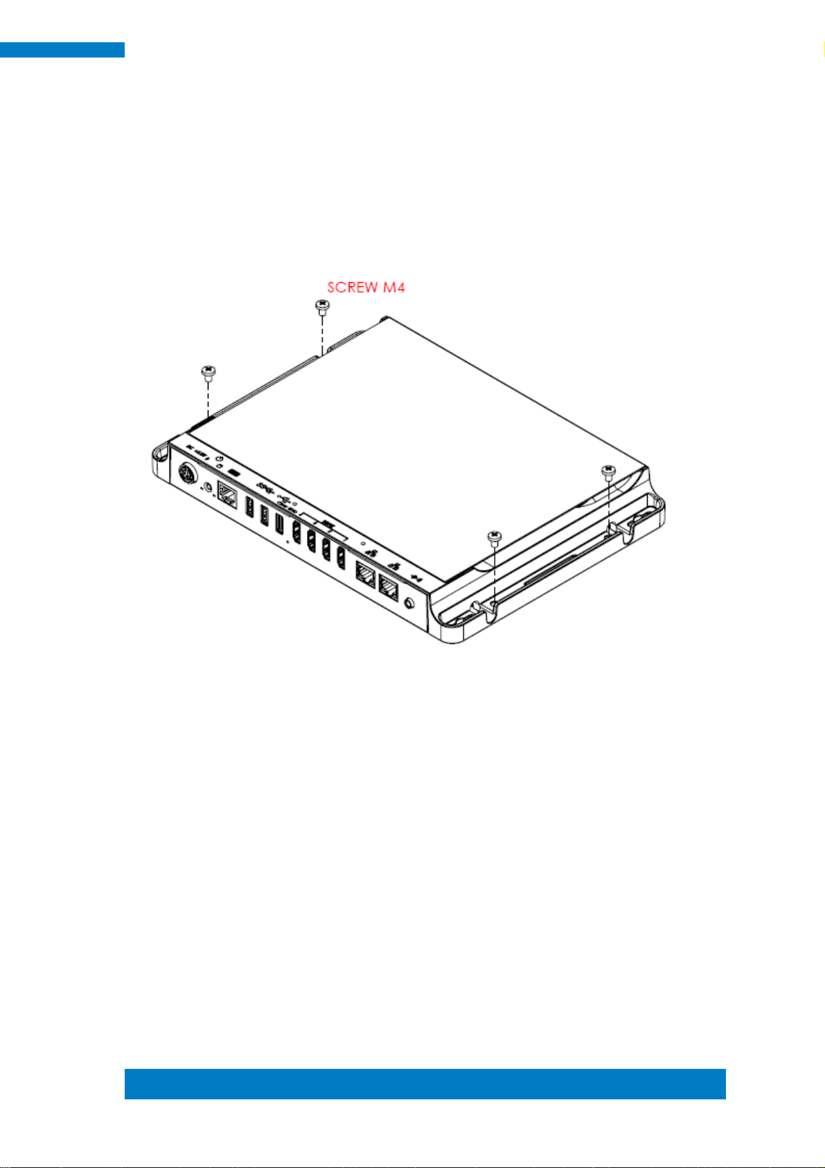
1.5 Hardware Installation
1.5.1 Mounting Installation
1. Please install SI-304 to the intended location using 4x M4*0.7*6L screws, as
shown in the picture.
Page 16
8
SI-304 User Manual
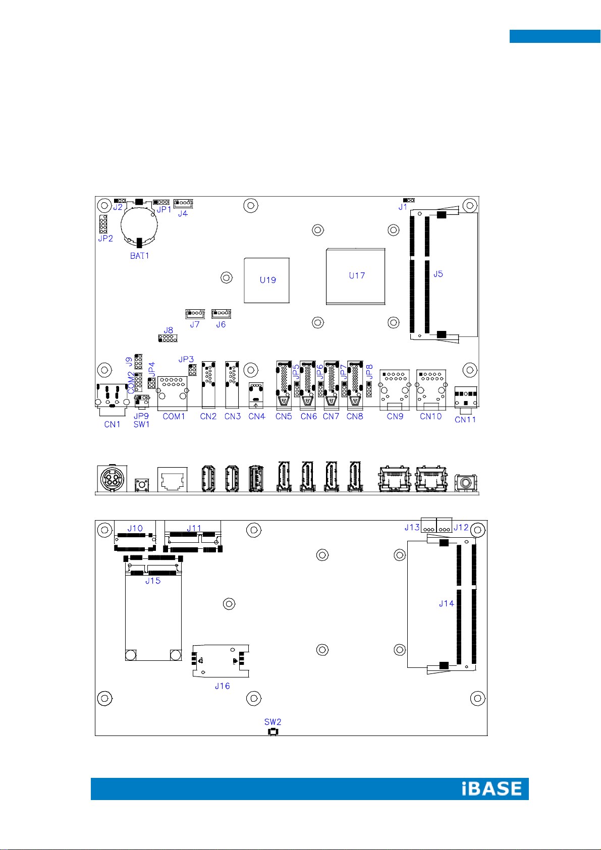
CHAPTER 2 MOTHERBOARD INTRODUCTION
2.1 Introduction
MBD304 Jumpers and Connectors
Page 17
Copyright © 2013 IBASE Technology Inc. All Rights
Reserved.
9
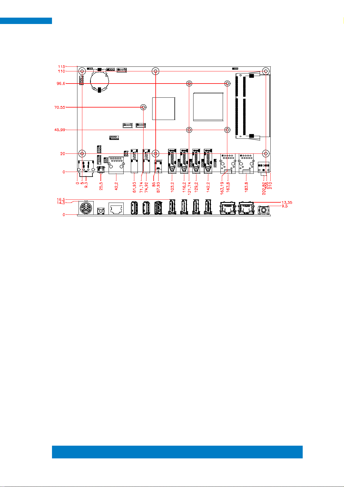
IBASE Technology Inc.
MBD304 Board Dimensions
Page 18
10
SI-304 User Manual
2.2 Installations
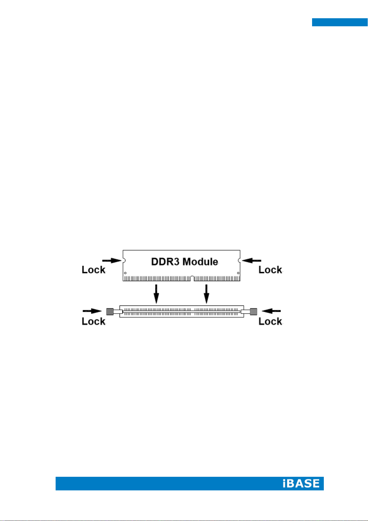
2.2.1 Installing the Memory
The MBD304 board supports four DDR3 memory modules for a maximum total of
32GB in DDR3 SODIMM memory type.
Installing and Removing Memory Modules
To install the DDR3 modules, locate the memory slot on the board and perform the
following steps:
1. Hold the DDR3 module so that the key of the DDR3 module aligned with that on
the memory slot.
2. Gently push the DDR3 module in an upright position until the clips of the slot close
to hold the DDR3 module in place when the DDR3 module touches the bottom of
the slot.
3. To remove the DDR3 module, press the clips with both hands.
Page 19

Copyright © 2013 IBASE Technology Inc. All Rights
Reserved.
11
IBASE Technology Inc.
JP4/JP5
Setting
Function
Pin 1-3
Short/Closed
+12V
Pin 3-4
Short/Closed
RI
Pin 3-5
Short/Closed
+5V
J2
Function
Normal
Clear CMOS
Pin #
Signal Name
1
+12V
2
+12V
3
GND
4
GND
5
GND
2.3 Setting the Jumpers
Jumpers are used on MBD304 to select various settings and features according to
your needs and applications. Contact your supplier if you have doubts about the best
configuration for your needs. The following lists the jumpers and connectors on
MBD304 and their respective functions.
JP3, JP4: COM1/COM2 RS232 RI/+5V/+12V Power Setting
J2: Clear CMOS Setting
CN1: DC_IN Connector (+12V Adaptor 4 Pin)
Page 20

12
SI-304 User Manual
J1
Function
1.5V
1.35V
COM1
Pin #
Signal Name
1
DSR, Data set ready
2
GND, ground
3
GND, ground
4
TXD, Transmit data
5
RXD, Receive data
6
DCD, Data carrier detect
7
DTR, Data terminal ready
8
CTS, Clear to send
9
RTS, Request to send
10
RI, Ring indicator
Signal Name
Pin #
Pin #
Signal Name
Data carrier detect
1 2 Data set ready
Receive data
3 4 Request to send
Transmit data
5 6 Clear to send
Data terminal
ready
7 8 Ring indicator
Ground
9
10
No connect.
J1: Memory Voltage Setting
COM1: COM1 Connector
COM2: COM2 Connector
Page 21

Copyright © 2013 IBASE Technology Inc. All Rights
Reserved.
13
IBASE Technology Inc.
Signal Name
Pin #
Pin #
Signal Name
Power BTN
1 2 Power BTN
HDD LED+
3 4 HDD LED-
Reset BTN
5 6 Reset BTN
VCC5V
7-8 FOR ID723
POWER USE
7
8
5VDUAL
7-8 FOR ID723
POWER USE
CN11: Audio Line out
JP2: SPI Flash Connector
J8: Half Mini PCIE Slot
J8: LPC Debug Port Connector
J22: Front Panel
JP1: DASH Programming header
J4: ISMART MCU Programming header
J6 J7: EDID Emulator MCU Programming header
CN9: LAN RTL8111EP-CG DASH
CN10: LAN RT8111G
CN5: HDMI (DP3)
CN6: HDMI (DP2)
CN7: HDMI (DP1)
CN8: HDMI (DP0)
J10: M.2 Socket SATA Only
J11/J6: Mini PCI-E With SIM Card Slot
J15: mSATA/Mini PCI-E
SW2: EDID Clear Button
Page 22

14
SI-304 User Manual
CHAPTER 3 BIOS SETUP
This chapter describes the different settings available in the AMI BIOS that comes
with the board. The topics covered in this chapter are as follows:
3.1 BIOS Introduction
The BIOS (Basic Input/Output System) installed in your computer system’s ROM
supports Intel processors. The BIOS provides critical low-level support for a standard
device such as disk drives, serial ports and parallel ports. It also password protection
as well as special support for detailed fine-tuning of the chipset controlling the entire
system.
3.2 BIOS Setup
The BIOS provides a Setup utility program for specifying the system configurations
and settings. The BIOS ROM of the system stores the Setup utility. When you turn on
the computer, the BIOS is immediately activated. Pressing the <Del> key immediately
allows you to enter the Setup utility. If you are a little bit late pressing the <Del> key,
POST (Power On Self Test) will continue with its test routines, thus preventing you from
invoking the Setup. If you still wish to enter Setup, restart the system by pressing
the ”Reset” button or simultaneously pressing the <Ctrl>, <Alt> and <Delete> keys.
You can also restart by turning the system Off and back On again. The following
message will appear on the screen:
Press <DEL> or <ESC> to Enter Setup
In general, you press the arrow keys to highlight items, <Enter> to select, the
<PgUp> and <PgDn> keys to change entries, <F1> for help and <Esc> to quit.
When you enter the Setup utility, the Main Menu screen will appear on the screen.
The Main Menu allows you to select from various setup functions and exit choices.
Page 23

Copyright © 2013 IBASE Technology Inc. All Rights
Reserved.
15
IBASE Technology Inc.
Main Advanced Chipset Boot Security Save & Exit
Choose the system default language
→ ← Select Screen
↑↓ Select Item
Enter: Select
+- Change Field
F1: General Help
F2: Previous Values
F3: Optimized Default
F4: Save
ESC: Exit
System Date
[Tue 01/20/2015]
System Time
[15:27:20]
Access Level
Administrator
Main Settings
Aptio Setup Utility – Copyright © 2012 American Megatrends, Inc.
System Date
Set the Date. Use Tab to switch between Data elements.
System Time
Set the Time. Use Tab to switch between Data elements.
Page 24

16
SI-304 User Manual
Main Advanced Chipset Boot Security Save & Exit
Launch PXE OpROM Disabled
→ ← Select Screen
↑↓ Select Item
Enter: Select
+- Change Field
F1: General Help
F2: Previous Values
F3: Optimized Default
F4: Save
ESC: Exit
► PCI Subsystem Settings
► ACPI Settings
► CPU Configuration
► IDE Configuration
► Shutdown Temperature Configuration
► iSmart Controller 3.1
► USB Configuration
►ASF Configuration
►MCTP Configuration
► F81846 Super IO Configuration
► F81846 H/W Monitor
Main Advanced Chipset Boot Security Save & Exit
PCI Bus Driver Version V 2.0502
→ ← Select Screen
↑↓ Select Item
Enter: Select
+- Change Field
F1: General Help
F2: Previous Values
F3: Optimized Default
F4: Save
ESC: Exit
►PCI Express Settings
Advanced Settings
This section allows you to configure and improve your system and allows you to set up some system
features according to your preference.
Aptio Setup Utility
PCI Subsystem Settings
Aptio Setup Utility
Page 25

Copyright © 2013 IBASE Technology Inc. All Rights
Reserved.
17
IBASE Technology Inc.
Main Advanced Chipset Boot Security Save & Exit
PCI Express Device Register Settings
→ ← Select Screen
↑↓ Select Item
Enter: Select
+- Change Field
F1: General Help
F2: Previous Values
F3: Optimized Default
F4: Save ESC: Exit
Relaxed Ordering
Enabled
Extended Tag
Disabled
No Snoop
Enabled
Maximum Payload
Auto
Maximum Read Request
Auto
PCI Express Link Register Settings
ASPM Support
Disabled
WARNING: Enabling ASPM may cause
some PCI-E devices to fail
Extended Synch
Disabled
Link Training Retry
5
Link Training Timeout (uS)
100
Unpopulated Links
Keep Link ON
Restore PCIE Registers
Disabled
PCI Express Settings
Aptio Setup Utility
Relaxed Ordering
Enables or disables PCI Express Device Relaxed Ordering.
Extended Tag
If ENABLED allows device to use 8-bit Tag field as a requester.
No Snoop
Enables or disables PCI Express Device No Snoop option.
Maximum Payload
Set Maximum Payload of PCI Express Device or allow System BIOS to select the value.
Maximum Read Request
Set Maximum Read Request Size of PCI Express Device or allow System BIOS to select the value.
ASPM Support
Set the ASPM Level: Force L0s – Force all links to L0s State:
AUTO – BIOS auto configure : DISABLE – Disables ASPM.
Extended Synch
If ENABLED allows generation of Extended Synchronization patterns.
Link Training Retry
Defines number of Retry Attempts software will take to retrain the link if previous training attempt was
unsuccessful.
Link Training Timeout (uS)
Defines number of Microseconds software will wait before polling ‘Link Training’ bit in Link Status
register. Value range from 10 to 1000 uS.
Page 26

18
SI-304 User Manual
Unpopulated Links
In order to save power, software will disable unpopulated PCI Express links, if this option set to
‘Disable Link’.
Restore PCIE Registers
On non-PCI Express aware OS’s (Pre Windows Vista)some devices may not be correctly
reinitialized after S3.Enabling this restors PCI Express device configuration on S3 resume
Warning : Enabling this may cause issues with other hardware after S3 resume.
Page 27

Copyright © 2013 IBASE Technology Inc. All Rights
Reserved.
19
IBASE Technology Inc.
Main Advanced Chipset Boot Security Save & Exit
ACPI Settings
→ ← Select Screen
↑↓ Select Item
Enter: Select
+- Change Field
F1: General Help
F2: Previous Values
F3: Optimized Default
F4: Save
ESC: Exit
Enable Hibernation
Enabled
ACPI Sleep State
S3 (Suspend to R…)
Lock Legacy Resources
Disabled
ACPI Settings
Aptio Setup Utility
Enable Hibernation
Enables or Disables System ability to Hibernate (OS/S4 Sleep State). This option may be not effective
with some OS.
ACPI Sleep State
Select ACPI sleep state the system will enter, when the SUSPEND button is pressed.
Lock Legacy Resources
Enabled or Disabled Lock of Legacy Resources.
Page 28

20
SI-304 User Manual
Main Advanced Chipset Boot Security Save & Exit
CPU Configuration
→ ← Select Screen
↑↓ Select Item
Enter: Select
+- Change Field
F1: General Help
F2: Previous Values
F3: Optimized Default
F4: Save
ESC: Exit
Module Version: 4.6.5.4 TrinityPI 026
AGESA Version: 1.1.0.7
PSS Support
Enable
PSTATE Adjustment
PPC Adjustment
Pstate 0
Pstate 0
► Node 0 Information
CPU Configuration
This section shows the CPU configuration parameters.
PSS Support
Enable/disable the generation of ACPI _PPC, _PPC, _PSS, and _PCT objects.
PSTATE Adjustment
Provide to adjust startup P-state level.
PPC Adjustment
Provide to adjust _PPC object.
Node 0 Information
View memory information related to Node 0.
Page 29

Copyright © 2013 IBASE Technology Inc. All Rights
Reserved.
21
IBASE Technology Inc.
Main Advanced Chipset Boot Security Save & Exit
IDE Configuration
→ ← Select Screen
↑↓ Select Item
Enter: Select
+- Change Field
F1: General Help
F2: Previous Values
F3: Optimized Default
F4: Save
ESC: Exit
SATA Port0
Not Present
SATA Port1
Not Present
Main Advanced Chipset Boot Security Save & Exit
→ ← Select Screen
↑↓ Select Item
Enter: Select
+- Change Field
F1: General Help
F2: Previous Values
F3: Optimized Default
F4: Save
ESC: Exit
APCI Shutdown Temperature
80 C/176 F
IDE Configuration
Shutdown Temperature Configuration
Aptio Setup Utility
Aptio Setup Utility
ACPI Shutdown Temperature
The default setting is 80 C/176 F.
Page 30

22
SI-304 User Manual
Main Advanced Chipset Boot Security Save & Exit
Auto Power On Schedule
→ ← Select Screen
↑↓ Select Item
Enter: Select
+- Change Field
F1: General Help
F2: Previous Values
F3: Optimized Default
F4: Save
ESC: Exit
Power-On after Power failure
PWR Resume Delay
Enable
Disable
Temperature Guardian
Disable
Schedule Slot 1
None
Schedule Slot 2
None
iSmart Controller 3.1
Power-On after Power failure
Aptio Setup Utility
This field sets the system power status whether Disable or Enable when power returns to the system
from a power failure situation.
PWR Resume Delay
Enable or disable power on resume delay.
Temperature Guardian
Generate the reset signal when system hangs up on POST.
Schedule Slot 1 / 2
Setup the hour/minute for system power on.
Page 31

Copyright © 2013 IBASE Technology Inc. All Rights
Reserved.
23
IBASE Technology Inc.
Main Advanced Chipset Boot Security Save & Exit
Alert Standard Format (ASF) Configuration
→ ← Select Screen
↑↓ Select Item
Enter: Select
+- Change Field
F1: General Help
F2: Previous Values
F3: Optimized Default
F4: Save ESC: Exit
ASF Support
ASF BIOS Mode
Disabled
ON
ASF WatchDog Timer
WatchDog Timer : BIOS
Disabled
0
WatchDog Timer : OS
0
Main Advanced Chipset Boot Security Save & Exit
Management Component Transport Protocol(MCTP) Configuration
→ ← Select Screen
↑↓ Select Item
Enter: Select
+- Change Field
F1: General Help
F2: Previous Values
F3: Optimized Default
F4: Save ESC: Exit
Realtek LAN card DASH function
Disabled
MCTP Support
Disabled
ASF Configuration
ASF Support
ASF Support Enable/Disable
Aptio Setup Utility
MCTP Configuration
Aptio Setup Utility
Realtek LAN card DASH function
Realtek LAN card DASH function Enable/Disable
Page 32

24
SI-304 User Manual
Main Advanced Chipset Boot Security Save & Exit
USB Configuration
→ ← Select Screen
↑↓ Select Item
Enter: Select
+- Change Field
F1: General Help
F2: Previous Values
F3: Optimized Default
F4: Save
ESC: Exit
USB Module Version
8.10.31
USB Devices:
1 Keyboard, 1 Mouse
Legacy USB Support
Enabled
XHCI Hand-off
Enabled
EHCI Hand-off
Enabled
USB Mass Storage Driver
Support
Enabled
Port 60/64 Emulation
Enabled
USB hardware delays and timeouts: USB Transfer time-out
20 sec
Device reset tine-out
20 sec
Device power-up delay
Auto
USB Configuration
Aptio Setup Utility
Legacy USB Support
Enables Legacy USB support.
AUTO option disables legacy support if no USB devices are connected.
DISABLE option keeps USB devices available only for EFI applications.
USB3.0 Support
Enable/Disable USB3.0 (XHCI) Controller support.
XHCI Hand-off
This is a workaround for OSes without XHCI hand-off support. The XHCI ownership change should
be claimed by XHCI driver.
EHCI Hand-off
Enabled/Disabled. This is a workaround for OSes without EHCI hand-off support. The EHCI
ownership change should be claimed by EHCI driver.
USB Transfer time-out
The time-out value for Control, Bulk, and Interrupt transfers.
Device reset time-out
USB mass Storage device start Unit command time-out.
Device power-up delay
Maximum time the device will take before it properly reports itself to the Host Controller. ‘Auto’ uses
default value: for a Root port it is 100ms, for a Hub port the delay is taken from Hub descriptor.
Page 33

Copyright © 2013 IBASE Technology Inc. All Rights
Reserved.
25
IBASE Technology Inc.
Main Advanced Chipset Boot Security Save & Exit
F81866 Super IO Configuration
→ ← Select Screen
↑↓ Select Item
Enter: Select
+- Change Field
F1: General Help
F2: Previous Values
F3: Optimized Default
F4: Save
ESC: Exit
F81866 Super IO Chip
F81846
► Serial Port 0 Configuration
► Serial Port 1 Configuration
Main Advanced Chipset Boot Security Save & Exit
PC Health Status
→ ← Select Screen
↑↓ Select Item
Enter: Select
+- Change Field
F1: General Help
F2: Previous Values
F3: Optimized Default
F4: Save
ESC: Exit
Fan1 smart fan control
Fan2 smart fan control
50 C
50C
CPU temperature
+56 C
System temperature
+45 C
Fan1 Speed
Fan2 Speed
N/A
N/A
Vcore
1.008 V
Vcc5V
+5.171 V
Vcc12V
+11.968 V
Memory Voltage
+1.512 V
VSB5V
5.1122 V
F81846 Super IO Configuration
Aptio Setup Utility
Serial Port Configuration
Set Parameters of Serial Ports. User can Enable/Disable the serial port and Select an optimal settings for
the Super IO Device.
F81846 H/W Monitor
Aptio Setup Utility
Temperatures/Voltages
These fields are the parameters of the hardware monitoring function feature of the
motherboard. The values are read-only values as monitored by the system and show
the PC health status.
Page 34

26
SI-304 User Manual
Main Advanced Chipset Boot Security Save & Exit
→ ← Select Screen
↑↓ Select Item
Enter: Select
+- Change Field
F1: General Help
F2: Previous Values
F3: Optimized Default
F4: Save
ESC: Exit
► GFX Configuration
► South Bridge
► North Bridge
Main Advanced Chipset Boot Security Save & Exit
GFX Configuration
→ ← Select Screen
↑↓ Select Item
Enter: Select
+- Change Field
F1: General Help
F2: Previous Values
F3: Optimized Default
F4: Save
ESC: Exit
Integrated Graphics
UMA Frame Buffer Size
Force
2G
PSPP Policy
Disabled
Chipset Settings
This section allows you to configure and improve your system and allows you to set up some system
features according to your preference.
Aptio Setup Utility
Aptio Setup Utility
Integrated Graphics
Options are Auto Disabled and Force
UMA Frame Buffer Size
Set UMA FB Size
PSPP Policy
PCIe Speed Power Policy
Page 35

Copyright © 2013 IBASE Technology Inc. All Rights
Reserved.
27
IBASE Technology Inc.
Main Advanced Chipset Boot Security Save & Exit
AMD Reference code Version: Trinity PI 1.1.0.7
Options for SATA Configuration
→ ← Select Screen
↑↓ Select Item
Enter: Select
+- Change Field
F1: General Help
F2: Previous Values
F3: Optimized Default
F4: Save
ESC: Exit
► SB SATA Configuration
Main Advanced Chipset Boot Security Save & Exit
→ ←Select Screen
↑↓ Select Item
Enter: Select
+- Change Field
F1: General Help
F2: Previous Values
F3: Optimized Default
F4: Save
ESC: Exit
OnChip SATA Channel
Enabled
OnChip SATA Type
AHCI
Aptio Setup Utility
Aptio Setup Utility
OnChip SATA Channel
Enabled or Disabled.
OnChip SATA Type
Native IDE /n RAID /n AHCI /n AHCI /n Legacy IDE /n IDE->AHCI /n HyperFlash
Page 36

28
SI-304 User Manual
Main Advanced Chipset Boot Security Save & Exit
North Bridge Configuration
→ ← Select Screen
↑↓ Select Item
Enter: Select
+- Change Field
F1: General Help
F2: Previous Values
F3: Optimized Default
F4: Save
ESC: Exit
Memory Information
Total memory: 2048 MB (DDR3)
► Socket 0 Information
Main Advanced Chipset Boot Security Save & Exit
Socket 0 Information
→ ←
Select Screen
↑↓ Select Item
Enter: Select
+- Change Field
F1: General Help
F2: Previous Values
F3: Optimized Default
F4: Save
ESC: Exit
Starting Address: 0KB
Ending Address: 2097151 KB
Dimm0: size=2048 MB,Dimm speed=1600 MHz
Dimm1: Not Present
Aptio Setup Utility
Aptio Setup Utility
Page 37

Copyright © 2013 IBASE Technology Inc. All Rights
Reserved.
29
IBASE Technology Inc.
Main Advanced Chipset Boot Security Save & Exit
Boot Configuration
→ ← Select Screen
↑↓ Select Item
Enter: Select
+- Change Field
F1: General Help
F2: Previous Values
F3: Optimized Default
F4: Save
ESC: Exit
Setup Prompt Timeout
1
Bootup NumLock State
Off
Quiet Boot
Disabled
Fast Boot
Disabled
Boot Mode select
LEGACY
FIXED BOOT ORDER Priorities
Boot Option #1
[Hard Disk]
Boot Option #2
[CD / DVD]
Boot Option #3
[USB Hard Disk]
Boot Option #4
[USB CD / DVD]
Boot Option #5
[USB Key :USB
Flash…]
Boot Option #6
[USB Floppy]
Boot Option #7
► CSM16 parameters
[Network]
CSM parameters
► USB Key Drive BBS Priorities
Boot Settings
This section allows you to configure the boot settings.
Aptio Setup Utility
Setup Prompt Timeout
Number of seconds to wait for setup activation key.
65535(0xFFFF) means indefinite waiting.
Bootup NumLock State
Select the keyboard NumLock state.
Quiet Boot
Enables/Disables Quiet Boot option.
Fast Boot
Enables/Disables boot with initialization of a minimal set of devices required to launch active boot
option. Has no effect for BBS boot options.
FIXED BOOT ORDER Priorities
Sets the system boot order.
CSM parameters
OpROM execution, boot options, filter, etc.
Page 38

30
SI-304 User Manual
Main Advanced Chipset Boot Security Save & Exit
→ ← Select Screen
↑↓ Select Item
Enter: Select
+- Change Field
F1: General Help
F2: Previous Values
F3: Optimized Default
F4: Save
ESC: Exit
Launch CSM
Always
Boot option filter
UEFI and Legacy
Launch PXE OpROM policy
Do not launch
Launch Storage OpROM policy
Legacy only
Launch Video OpROM policy
Legacy only
Other PCI device ROM priority
UEFI OpROM
CSM parameters
This section allows you to configure the boot settings.
Aptio Setup Utility
Launch CSM
This option controls if CSM will be launched.
Boot option filter
This option controls what devices system can boot to.
Launch PXE OpROM policy
Controls the execution of UEFI and Legacy PXE OpROM.
Launch Storatge OpROM policy
Controls the execution of UEFI and Legacy Storage OpROM.
Launch Video OpROM policy
Controls the execution of UEFI and Legacy Video OpROM.
Other PCI device ROM priority
For PCI devices other than Network, Mass storage or Video defines which OpROM to launch.
Page 39

Copyright © 2013 IBASE Technology Inc. All Rights
Reserved.
31
IBASE Technology Inc.
Main Advanced Chipset Boot Security Save & Exit
Password Description
→ ← Select Screen
↑↓ Select Item
Enter: Select
+- Change Field
F1: General Help
F2: Previous Values
F3: Optimized Default
F4: Save
ESC: Exit
If ONLY the Administrator’s password is set,
then this only limit access to Setup and is only
asked for when entering Setup.
If ONLY the User’s password is set, then this is a
power on password and must be entered to boot
or enter Setup. In Setup the User will have
Administrator rights
The password length must be
in the following range:
Minimum length
3
Maximum length
20
Administrator Password
User Password
Security Settings
This section allows you to configure and improve your system and allows you to set up some system
features according to your preference.
Aptio Setup Utility
Administrator Password
Set Setup Administrator Password.
User Password
Set User Password.
Secure Boot control
Secure Boot flow control.
Secure Boot is possible only if System runs in User Mode.
Secure Boot Policy
Select Secure Boot mode extended options: Internal FV, Option ROM, Removable Media, Fixed Media.
Administrator Password
Set Setup Administrator Password
Page 40

32
SI-304 User Manual
Main Advanced Chipset Boot Security Save & Exit
Save Changes and Exit
→ ← Select Screen
↑↓ Select Item
Enter: Select
+- Change Field
F1: General Help
F2: Previous Values
F3: Optimized Default
F4: Save
ESC: Exit
Discard Changes and Exit
Save Changes and Reset
Discard Changes and Reset
Save Options
Save Changes
Discard Changes
Restore Defaults
Save as User Defaults
Restore User Defaults
Save & Exit Settings
Save Changes and Exit
Exit system setup after saving the changes.
Discard Changes and Exit
Exit system setup without saving any changes.
Save Changes and Reset
Reset the system after saving the changes.
Discard Changes and Reset
Reset system setup without saving any changes.
Save Changes
Save Changes done so far to any of the setup options.
Discard Changes
Discard Changes done so far to any of the setup options.
Restore Defaults
Restore/Load Defaults values for all the setup options.
Save as User Defaults
Save the changes done so far as User Defaults.
Restore User Defaults
Restore the User Defaults to all the setup options.
Page 41

Copyright © 2013 IBASE Technology Inc. All Rights
Reserved.
33
IBASE Technology Inc.
CHAPTER 4 DRIVERS INSTALLATION
IMPORTANT NOTE:
After installing your Windows operating system, you must install first the Intel Chipset Software
Installation Utility before proceeding with the drivers installation.
4.1 VGA Drivers Installation
1. Insert the drivers DVD that comes with the board. Click AMD, then AMD A77E Chipset Drivers.
2. Click AMD A77E Series Graphics Drivers.
Page 42

34
SI-304 User Manual
3. When the welcome screen appears, click Next.
4. Select the language you would like to be displayed and click Next.
5. Click Next to continue the installation process.
Page 43

Copyright © 2013 IBASE Technology Inc. All Rights
Reserved.
35
IBASE Technology Inc.
6. Select Express and the installation location and click Next.
Page 44

36
SI-304 User Manual
7. Click Accept to accept the End User License Agreement.
8. To reboot the system, click Yes.
Page 45

Copyright © 2013 IBASE Technology Inc. All Rights
Reserved.
37
IBASE Technology Inc.
4.2 Audio Drivers Installation
1. Insert the drivers DVD that comes with the board. Click AMD, then Realtek High Definition
Audio Driver.
2. When the Welcome screen to the InstallShield Wizard appears, click Next.
3. InstallShield Wizard is now complete, click Finish to restart the system and for changes to
take effect.
Page 46

38
SI-304 User Manual
4.3 LAN Drivers Installation
1. Insert the drivers DVD that comes with the board. Click LAN Card.
2. Click Realtek LAN Controller Drivers.
3. Click Realtek RTL8111EP LANDrivers.
4. When the Welcome screen appears, click Next.
5. click Install to begin the installation.
6. InstallShield Wizard is complete. Click Finish.
Page 47

Copyright © 2013 IBASE Technology Inc. All Rights
Reserved.
39
IBASE Technology Inc.
Appendix
A. ATI Eyefinitity setting
After finishing AMD VGA driver installation, you can start to use “AMD Catalyst
Control Center”.
Choose “AMD Eyefinity Multi-Display” for Video wall display configuration
setting.
Page 48

40
SI-304 User Manual
Select “Create Eyefinity Display Group”
Page 49

Copyright © 2013 IBASE Technology Inc. All Rights
Reserved.
41
IBASE Technology Inc.
Select “2 x 2” for the Display configuration
Page 50

42
SI-304 User Manual
Make the displays arrangement
Page 51

Copyright © 2013 IBASE Technology Inc. All Rights
Reserved.
43
IBASE Technology Inc.
Complete the settings
Page 52

44
SI-304 User Manual
Now, you can use Screen resolution to check your setting.
A screen with 7680 X 4320 is the correct setting for 2 x 2 Display configuration.
(Monitor: ASUS PB287Q with 3840 * 2160 resolution support.)
Page 53

Copyright © 2013 IBASE Technology Inc. All Rights
Reserved.
45
IBASE Technology Inc.
Remarks:
3 and 4 Displays configurations
Page 54

46
SI-304 User Manual
Address
Device Description
0000h-03AFh
PCI bus
0000h-03AFh
Direct memory access controller
0010h-001Fh
Motherboard resources
0020h-0021h
Programmable interrupt controller
0022h-003Fh
Motherboard resources
0040h-0043h
System timer
0044h-005Fh
Motherboard resources
0060h-0060h
Standard PS/2 Keyboard
0061h-0061h
System speaker
0063h-0063h
Motherboard resources
0064h-0064h
Standard 101/102-Key or Microsoft Natural PS/2 Keyboard
0065h-0065h
Motherboard resources
0070h-0071h
System CMOS/real time clock
0072h-007Fh
Motherboard resources
0081h-0083h
Direct memory access controller
0084h-0086h
Motherboard resources
0084h-0087h
Direct memory access controller
00A0h-00A1h
Programmable interrupt controller
00A2h-00BFh
Motherboard resources
00A2h-00BFh
Direct memory access controller
00B1h-00B1h
Motherboard resources
00F0h-00FFh
Numeric data processor
0170h-0177h
ATA Channel 1
01F0h-01F7h
ATA Channel 0
0238H-023Fh
Communications Port (COM5)
02E8H-02EFh
Communications Port (COM4)
02F8H-02FFh
Communications Port (COM2)
0338H-033Fh
Communications Port (COM6)
03E8H-03EFh
Communications Port (COM3)
03F8H-03FFh
Communications Port (COM1)
B. I/O Port Address Map
Each peripheral device in the system is assigned a set of I/O port addresses, which
also becomes the identity of the device. The following table lists the I/O port
addresses used.
Page 55

Copyright © 2013 IBASE Technology Inc. All Rights
Reserved.
47
IBASE Technology Inc.
Level
Function
IRQ 0
System timer
IRQ 1
Standard 101/102-Key
IRQ 3
Communications Port (COM2)
IRQ 4
Communications Port (COM1)
IRQ 6
Communications Port (COM3)
IRQ 6
Communications Port (COM4)
IRQ 8
System CMOS/real time clock
IRQ 10
Communications Port (COM5)
IRQ 10
Communications Port (COM6)
IRQ 12
PS/2 Compatible Mouse
IRQ 13
Numeric data processor
IRQ 16
High Definition Audio Controller
IRQ 16
PCI standard PCI-to-PCI bridge
IRQ 17
Standard Enhanced PCI to USB Host Controller
IRQ 17
Standard Enhanced PCI to USB Host Controller
IRQ 18
High Definition Audio Controller
IRQ 18
Standard Open HCD USB Host Controller
IRQ 18
Standard Open HCD USB Host Controller
IRQ 18
Standard Open HCD USB Host Controller
IRQ 18
Standard Open HCD USB Host Controller
IRQ 19
PCI standard PCI-to-PCI bridge
IRQ 19
AMD SATA Controller (IDE Mode)
C. Interrupt Request Lines (IRQ)
Peripheral devices use interrupt request lines to notify CPU for the service required.
The following table shows the IRQ used by the devices on board.
Page 56

48
SI-304 User Manual
D. Watchdog Timer Configuration
The WDT is used to generate a variety of output signals after a user programmable count. The
WDT is suitable for use in the prevention of system lock-up, such as when software becomes
trapped in a deadlock. Under these sorts of circumstances, the timer will count to zero and the
selected outputs will be driven. Under normal circumstance, the user will restart the WDT at
regular intervals before the timer counts to zero.
SAMPLE CODE:
//--------------------------------------------------------------------------//
// THIS CODE AND INFORMATION IS PROVIDED "AS IS" WITHOUT WARRANTY OF ANY
// KIND, EITHER EXPRESSED OR IMPLIED, INCLUDING BUT NOT LIMITED TO THE
// IMPLIED WARRANTIES OF MERCHANTABILITY AND/OR FITNESS FOR A PARTICULAR
// PURPOSE.
//
//--------------------------------------------------------------------------#include <dos.h>
#include <conio.h>
#include <stdio.h>
#include <stdlib.h>
#include "F81866.H"
//--------------------------------------------------------------------------int main (int argc, char *argv[]);
void EnableWDT(int);
void DisableWDT(void);
//--------------------------------------------------------------------------int main (int argc, char *argv[])
{
unsigned char bBuf;
unsigned char bTime;
char **endptr;
char SIO;
printf("Fintek 81866 watch dog program\n");
SIO = Init_F81866();
Page 57

Copyright © 2013 IBASE Technology Inc. All Rights
Reserved.
49
IBASE Technology Inc.
if (SIO == 0)
printf("Can not detect Fintek 81866, program abort.\n");
return(1);
}//if (SIO == 0)
if (argc != 2)
{
printf(" Parameter incorrect!!\n");
return (1);
}
bTime = strtol (argv[1], endptr, 10);
printf("System will reset after %d seconds\n", bTime);
if (bTime)
{EnableWDT(bTime); }
else
{DisableWDT();}
return 0;
}
//--------------------------------------------------------------------------void EnableWDT(int interval)
{
unsigned char bBuf;
bBuf = Get_F81866_Reg(0x2B);
bBuf &= (~0x20);
Set_F81866_Reg(0x2B, bBuf);
/Enable WDTO
Set_F81866_LD(0x07);
//switch to logic device 7
Set_F81866_Reg(0x30, 0x01);
//enable timer
bBuf = Get_F81866_Reg(0xF5);
bBuf &= (~0x0F);
bBuf |= 0x52;
Page 58

50
SI-304 User Manual
Set_F81866_Reg(0xF5, bBuf);
//count mode is second
Set_F81866_Reg(0xF6, interval);
//set timer
bBuf = Get_F81866_Reg(0xFA);
bBuf |= 0x01;
Set_F81866_Reg(0xFA, bBuf);
//enable WDTO output
bBuf = Get_F81866_Reg(0xF5);
bBuf |= 0x20;
Set_F81866_Reg(0xF5, bBuf);
//start counting
}
//--------------------------------------------------------------------------void DisableWDT(void)
{
unsigned char bBuf;
Set_F81866_LD(0x07);
//switch to logic device 7
bBuf = Get_F81866_Reg(0xFA);
bBuf &= ~0x01;
Set_F81866_Reg(0xFA, bBuf);
//disable WDTO output
bBuf = Get_F81866_Reg(0xF5);
bBuf &= ~0x20;
bBuf |= 0x40;
Set_F81866_Reg(0xF5, bBuf);
//disable WDT
}
//---------------------------------------------------------------------------
Page 59

Copyright © 2013 IBASE Technology Inc. All Rights
Reserved.
51
IBASE Technology Inc.
//--------------------------------------------------------------------------//
// THIS CODE AND INFORMATION IS PROVIDED "AS IS" WITHOUT WARRANTY OF ANY
// KIND, EITHER EXPRESSED OR IMPLIED, INCLUDING BUT NOT LIMITED TO THE
// IMPLIED WARRANTIES OF MERCHANTABILITY AND/OR FITNESS FOR A PARTICULAR
// PURPOSE.
//
//--------------------------------------------------------------------------#include "F81866.H"
#include <dos.h>
//--------------------------------------------------------------------------unsigned int F81866_BASE;
void Unlock_F81866 (void);
void Lock_F81866 (void);
//--------------------------------------------------------------------------unsigned int Init_F81866(void)
{
unsigned int result;
unsigned char ucDid;
F81866_BASE = 0x4E;
result = F81866_BASE;
ucDid = Get_F81866_Reg(0x20);
if (ucDid == 0x07)
//Fintek 81866
{goto Init_Finish; }
F81866_BASE = 0x2E;
result = F81866_BASE;
ucDid = Get_F81866_Reg(0x20);
if (ucDid == 0x07)
//Fintek 81866
{goto Init_Finish; }
F81866_BASE = 0x00;
result = F81866_BASE;
Page 60

52
SI-304 User Manual
Init_Finish:
return (result);
}
//--------------------------------------------------------------------------void Unlock_F81866 (void)
{
outportb(F81866_INDEX_PORT, F81866_UNLOCK);
outportb(F81866_INDEX_PORT, F81866_UNLOCK);
}
//--------------------------------------------------------------------------void Lock_F81866 (void)
{
outportb(F81866_INDEX_PORT, F81866_LOCK);
}
//--------------------------------------------------------------------------void Set_F81866_LD( unsigned char LD)
{
Unlock_F81866();
outportb(F81866_INDEX_PORT, F81866_REG_LD);
outportb(F81866_DATA_PORT, LD);
Lock_F81866();
}
//--------------------------------------------------------------------------void Set_F81866_Reg( unsigned char REG, unsigned char DATA)
{
Unlock_F81866();
outportb(F81866_INDEX_PORT, REG);
outportb(F81866_DATA_PORT, DATA);
Lock_F81866();
}
//---------------------------------------------------------------------------
Page 61

Copyright © 2013 IBASE Technology Inc. All Rights
Reserved.
53
IBASE Technology Inc.
unsigned char Get_F81866_Reg(unsigned char REG)
{
unsigned char Result;
Unlock_F81866();
outportb(F81866_INDEX_PORT, REG);
Result = inportb(F81866_DATA_PORT);
Lock_F81866();
return Result;
}
//---------------------------------------------------------------------------
//--------------------------------------------------------------------------//
// THIS CODE AND INFORMATION IS PROVIDED "AS IS" WITHOUT WARRANTY OF ANY
// KIND, EITHER EXPRESSED OR IMPLIED, INCLUDING BUT NOT LIMITED TO THE
// IMPLIED WARRANTIES OF MERCHANTABILITY AND/OR FITNESS FOR A PARTICULAR
// PURPOSE.
//
//--------------------------------------------------------------------------#ifndef __F81866_H
#define __F81866_H
1
//--------------------------------------------------------------------------#define
F81866_INDEX_PORT
(F81866_BASE)
#define
F81866_DATA_PORT
(F81866_BASE+1)
//---------------------------------------------------------------------------
Page 62

54
SI-304 User Manual
#define
F81866_REG_LD
0x07
//--------------------------------------------------------------------------#define F81866_UNLOCK
0x87
#define
F81866_LOCK
0xAA
//--------------------------------------------------------------------------unsigned int Init_F81866(void);
void Set_F81866_LD( unsigned char);
void Set_F81866_Reg( unsigned char, unsigned char);
unsigned char Get_F81866_Reg( unsigned char);
//--------------------------------------------------------------------------#endif
//__F81866_H
 Loading...