

Page 1
www.ibase.com.tw
IBASE Technology Inc.
SI-12 Series
User Manual
Page 2

Copyright © 2013 IBASE Technology Inc. All Rights Reserved. 2
2
SI-12 User Manual
Revision
Release Date
V0.1
2014/06/20
V0.2
2014/09/23
Page 3

1
SI-12 User Manual
Copyright © 2013 IBASE Technology Inc. All Rights Reserved.
No part of this manual, including the products and software described in it, may be
reproduced, transmitted, transcribed, stored in a retrieval system, or translated into
any language in any form or by any means, except documentation kept by the
purchaser for backup purposes, without the express written permission of IBASE
Technology INC. (“IBASE”).
Products and corporate names mentioned in this manual may or may not be
registered trademarks or copyrights of their respective companies, and are used for
identification purposes only. All trademarks are the property of their respective
owners.
Every effort has been made to ensure that the contents of this manual are correct and
up to date. However, the manufacturer makes no guarantee regarding the accuracy of
its contents, and reserves the right to make changes without prior notice.
Page 4

2
SI-12 User Manual
Table of Contents
Setting up your system ......................................................................................................... i
Care during use .................................................................................................................... ii
Acknowledgments .............................................................................................................. iii
CHAPTER 1 INTRODUCTION .................................................................................... 1
1.1 General Description ....................................................................................................... 1
1.2 System Specifications..................................................................................................... 2
1.2.1 Hardware Specifications ............................................................................................. 2
1.2.2 Dimensions ................................................................................................................. 3
1.2.3 I/O View ...................................................................................................................... 4
1.3 Exploded View of the SI-12 Assembly ........................................................................... 5
1.3.1 Parts Description ......................................................................................................... 5
1.4 Packing List ..................................................................................................................... 5
1.4.1 Optional Items ............................................................................................................ 6
1.5 HARDWARE INSTALLATION ............................................................................................ 7
1.5.1 Installing the Wireless Module ................................................................................... 7
1.5.2 Installing the mSATA Module ...................................................................................... 9
1.5.3 Installing the HDMI Cable Holder ............................................................................. 11
CHAPTER 2 MOTHERBOARD INTRODUCTION .........................................................12
2.1 Introduction ................................................................................................................. 12
2.2 Installing the Memory ................................................................................................. 14
2.3 Setting the Jumpers ..................................................................................................... 15
2.4 Connectors on IB812 .................................................................................................... 16
CHAPTER 3 BIOS SETUP .........................................................................................18
3.1 BIOS Introduction......................................................................................................... 18
3.2 BIOS Setup.................................................................................................................... 18
CHAPTER 4 DRIVERS INSTALLATION .......................................................................32
4.1 Intel Chipset Software Installation Utility ................................................................... 32
4.2 VGA Drivers Installation ............................................................................................... 33
4.3 Realtek High Definition Audio Driver Installation ....................................................... 34
4.4 Intel Trusted Execution Engine Installation ................................................................. 35
4.5 LAN Drivers Installation ............................................................................................... 36
4.6 Intel® USB 3.0 Drivers .................................................................................................. 37
Appendix ...............................................................................................................38
Mounting SI-12 to the Wall................................................................................................ 38
Wall Mounting Requirements............................................................................................ 39
SI-12 Mounting Bracket Solution ....................................................................................... 40
Page 5

i
SI-12 User Manual
Safety Information
Your SI-12 is designed and tested to meet the latest standards of safety for
information technology equipment. However, to ensure your safety, it is important that
you read the following safety instructions
Setting up your system
Read and follow all instructions in the documentation before you operate your
system.
Do not use this product near water.
Set up the system on a stable surface. Do not secure the system on any unstable
plane.
Do not place this product on an unstable cart, stand, or table. The product may
fall, causing serious damage to the product.
Slots and openings on the chassis are for ventilation. Do not block or cover these
openings. Make sure you leave plenty of space around the system for ventilation.
Never insert objects of any kind into the ventilation openings.
This system should be operated from the type of power indicated on the marking
label. If you are not sure of the type of power available, consult your dealer or
local power company.
Use this product in environments with ambient temperatures between -30˚C and
60˚C.
If you use an extension cord, make sure that the total ampere rating of the
devices plugged into the extension cord does not exceed its ampere rating.
DO NOT LEAVE THIS EQUIPMENT IN AN ENVIRONMENT WHERE THE
STORAGE TEMPERATURE MAY GO BELOW -40° C (-40° F) OR ABOVE 80°
C (176° F). THIS COULD DAMAGE THE EQUIPMENT. THE EQUIPMENT
SHOULD BE IN A CONTROLLED ENVIRONMENT.
Page 6

ii
SI-12 User Manual
Care during use
Do not walk on the power cord or allow anything to rest on it.
Do not spill water or any other liquids on your system.
When the system is turned off, a small amount of electrical current still flows.
Always unplug all power, and network cables from the power outlets before
cleaning the system.
If you encounter the following technical problems with the product, unplug the
power cord and contact a qualified service technician or your retailer.
The power cord or plug is damaged.
Liquid has been spilled into the system.
The system does not function properly even if you follow the operating
instructions.
The system was dropped or the cabinet is damaged.
Lithium-Ion Battery Warning
CAUTION: Danger of explosion if battery is incorrectly replaced. Replace only with
the same or equivalent type recommended by the manufacturer. Dispose of used
batteries according to the manufacturer’s instructions.
NO DISASSEMBLY
The warranty does not apply to the products that have been disassembled by users
WARNING
HAZARDOUS MOVING PARTS
KEEP FINGERS AND OTHER BODY PARTS AWAY
Page 7

Copyright © 2013 IBASE Technology Inc. All Rights Reserved.
iii
IBASE Technology Inc.
Acknowledgments
AMI is a registered trademark of AMI Software International, Inc.
AMD and ATI are registered trademarks of AMD Corporation.
Microsoft Windows is a registered trademark of Microsoft Corporation.
FINTEK is a registered trademark of FINTEK Electronics Corporation.
REALTEK is a registered trademark of REALTEK Electronics Corporation.
All other product names or trademarks are properties of their respective
owners.
Page 8

Page 9

1
SI-12 User Manual
CHAPTER 1 INTRODUCTION
1.1 General Description
The “Signature Book™” SI-12 is a professional fanless digital signage system
powered by Intel® Atom™ E3845 Quad-Core @ 1.91GHz Processor and Intel®
(Gen7-LP) 4EU Graphics. This compact & slim design supports 2x HDMI, 1x RJ45 for
LAN, 1x RJ45 for RS232, 2x USB2.0 and 1x USB3.0 port to give a wide selection for
data communication functionality in display applications.
Page 10
2
SI-12 User Manual
Model Name
SI-12
System Mainboard
IB812
CPU
Intel Atom E3840 SoC (22nm); 4 Cores @ 1.91 GHz
Chipset
FCBGA package (25mm x 27mm)
Memory
2 x DDR3L@ 1.35V SO-DIMM, Dual Channel (Max.
16GB) ,No-ECC
I/O Interface
2x HDMI
1x USB 3.0 port, 2x USB 2.0 ports
1x RJ45 for LAN, 1x RJ45 for RS232
2x audio connectors for Line-in / Line-out
Power / HDD LED, 1x power on/off button
1x DC jack
Storage
1x mSATA
Expansion Slots
1x mPCIe(x1) for WiFi + Bluetooth, 3G, and TV tuner
options
1x UIM/SIM card slot (for 3G/LTE adapter in mPCIe slot)
Power Supply
+12V DC-in with 60W power adaptor
Construction
Aluminum + SGCC
Chassis Color
Black & White
Mounting
STD system bracket
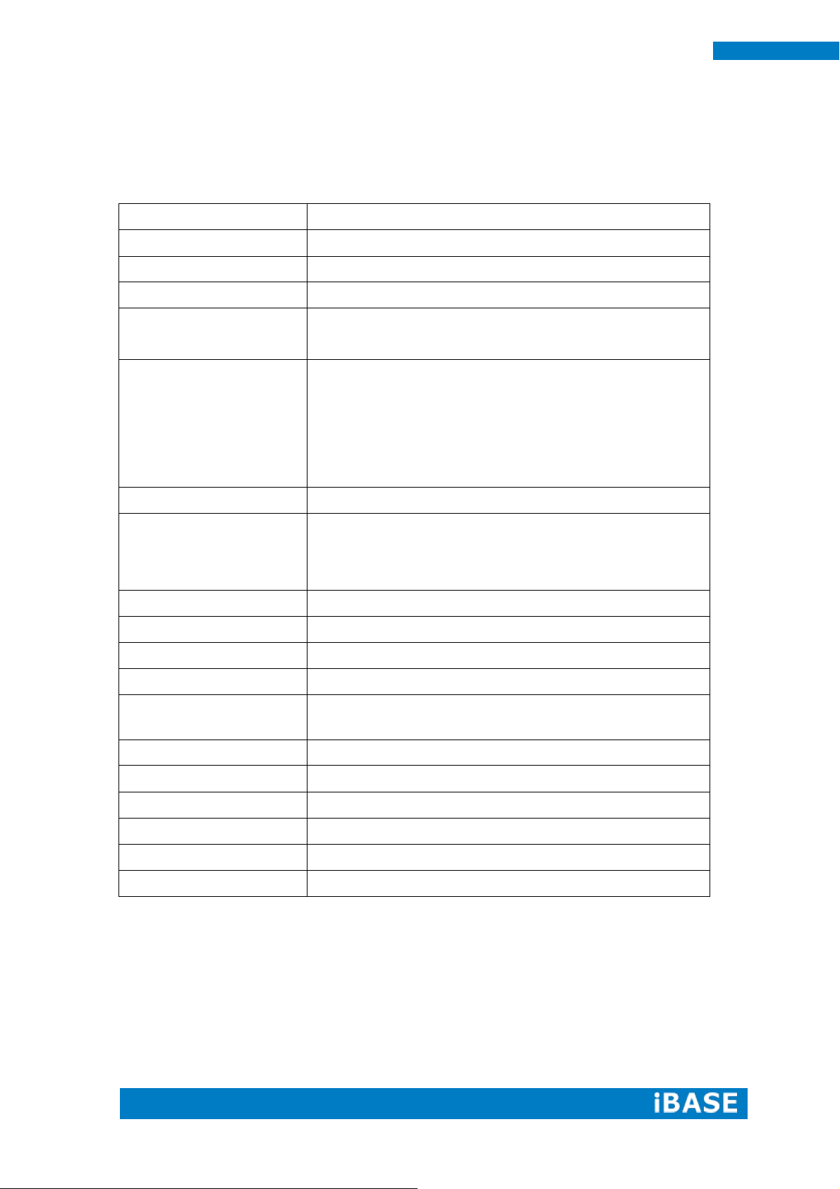
Dimensions
190mm(W) x 130mm(D) x 19.5mm(H)
7.5”(W) x 5.1”(D) x 0.77”(H)
Operating Temperature
-30°C ~ 60°C (-22°F~140°F)
Storage Temperature
-40°C ~ 80°C (-40°F~176°F)
Relative Humidity
5~90% @45°C (non-condensing)
Vibration
mSATA: 5 Grms/5~500Hz random operation
RoHS
Available
Certification
CE, FCC, UL, CCC
1.2 System Specifications
1.2.1 Hardware Specifications
‧
This specification is subject to change without prior notice.
Page 11
Copyright © 2013 IBASE Technology Inc. All Rights Reserved.
3
IBASE Technology Inc.
1.2.2 Dimensions
Page 12
4
SI-12 User Manual
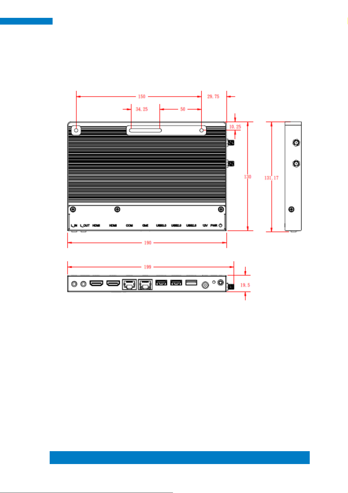
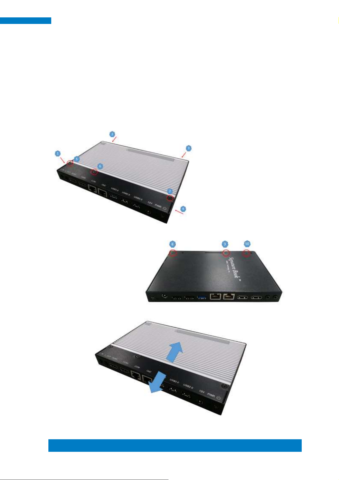
Item
Connector
Item
Connector
1
Line-in
6
1x USB 3.0
2
Line-out
7
2x USB 2.0
3
2x HDMI
8
DC jack
4
1x RJ45 for RS232
9
Power LED
5
1x RJ45 for LAN
10
Power on/off button
1.2.3 I/O View
Page 13
Copyright © 2013 IBASE Technology Inc. All Rights Reserved.
5
IBASE Technology Inc.
Part No.
Description
Part No.
Description
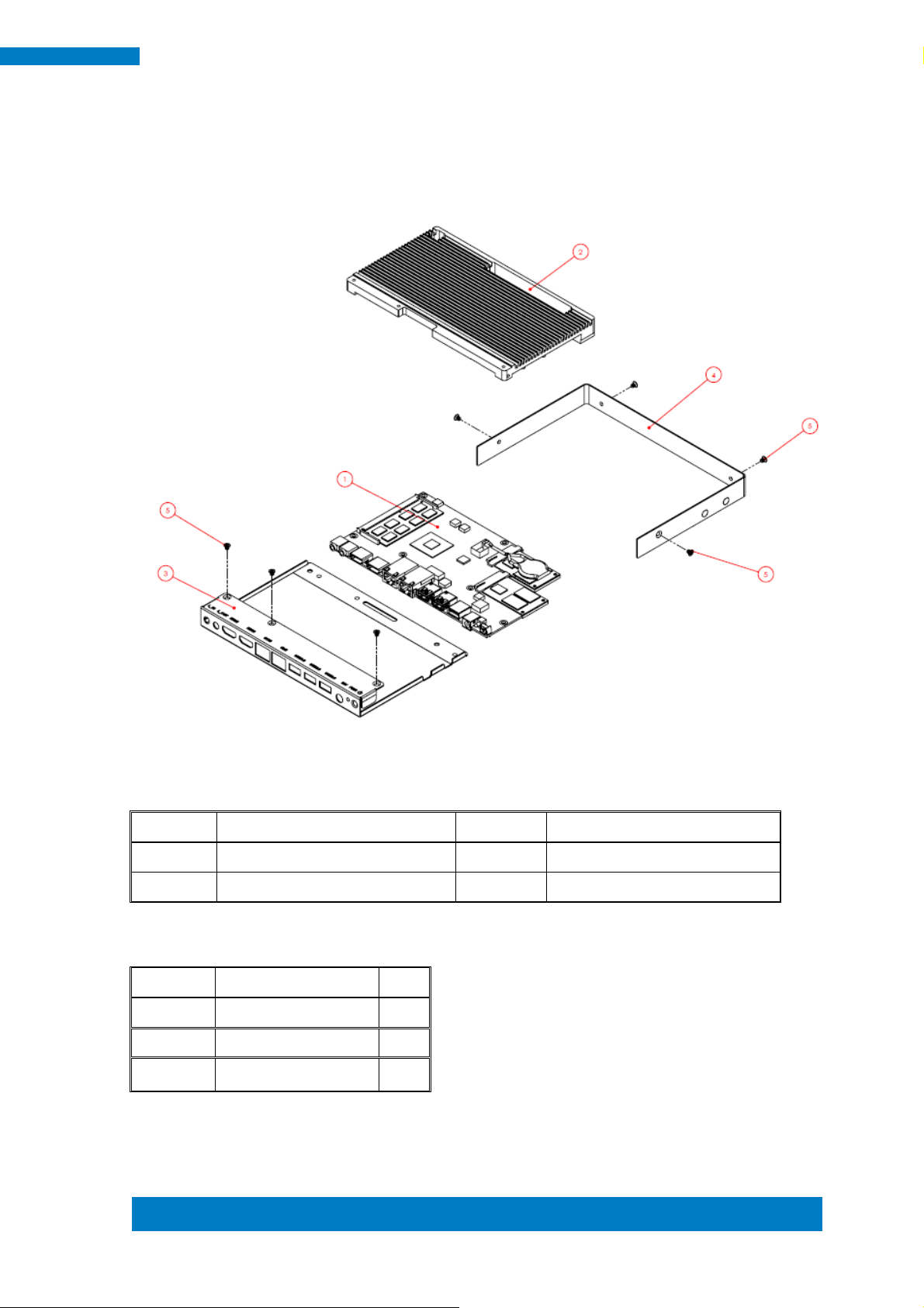
1
IB812 motherboard
2
SI-12 heat sink
3
SI-12 Base
4
SI-12 Cover
Item No.
Description
Qty
1
Driver CD
1
2
Power adaptor
1
3
Power Cord
1
1.3 Exploded View of the SI-12 Assembly
1.3.1 Parts Description
1.4 Packing List
Page 14
6
SI-12 User Manual
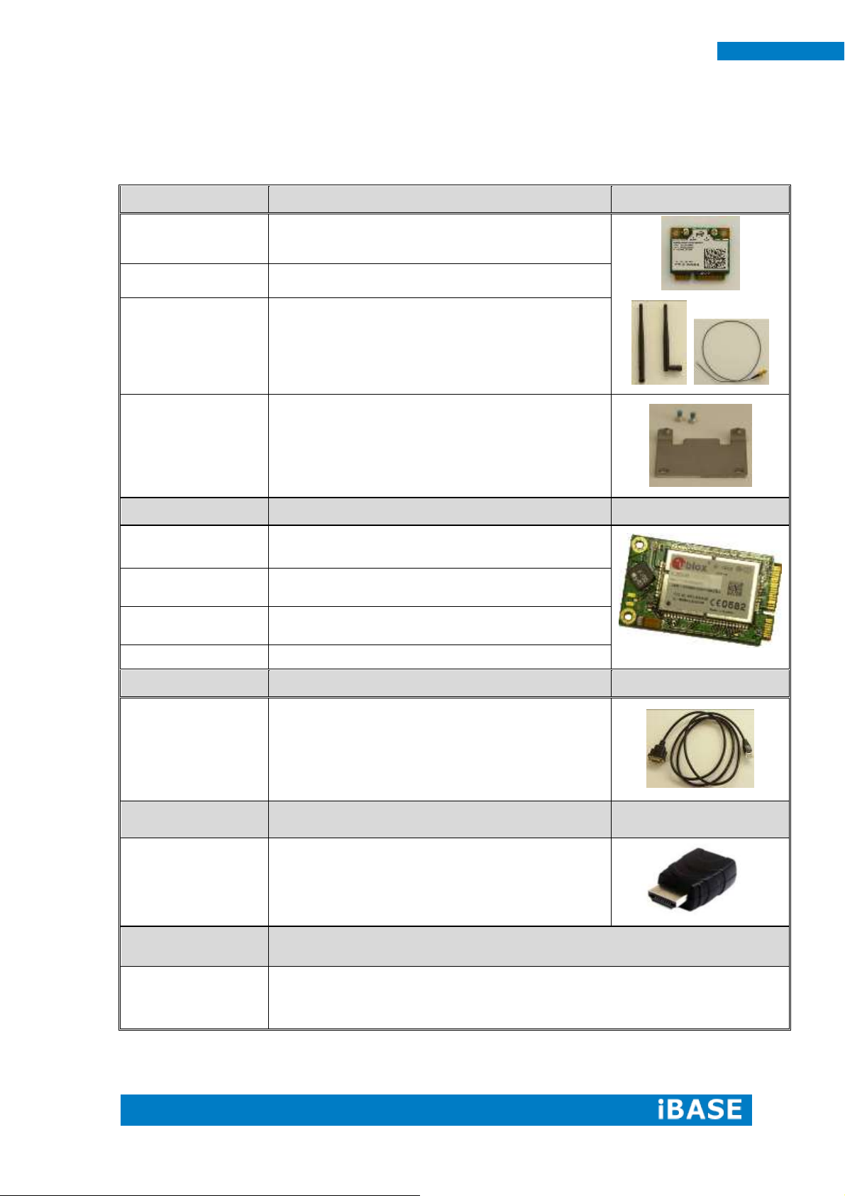
WiFi Solution
Description
QCOM WiFi Module
WIRELESS;PCI-E MINI CARD 802.11B/G/N
[AW-NE238H] (A008WLAWNE238H000P)
External Antenna
-2pcs
WiFi Antenna (A055RFA02C2M20800P)
Internal Cable -2pcs
Internal Antenna 100mm[ BTC130-1-70B-100]RoHS
(A055RFA0000021000P)
Bracket
COMPONENT BOM;MPCIE-EXT V-B2 BRACKET
BOM RoHS (SC2MPCIEEXT0B2100P)
3G Solution
Description
ZU 202
Wireless; 3.75G UMTS/HSPA [ZU202] RoHS
(A008WIRELESS00520P)
ZU 200
Wireless; 3.75G UMTS/HSPA & GPS Module
[ZU200] RoHS (A008WIRELESS00510P)
Cable
Cable; Antenna-2 30CM P 2pcs
(C501ANT0200300000P)
Antenna
Antenna; 3G, P, 2pcs (A055ANT0921Q2P000P)
COM Port Cable
Description
EXT-424
Cable; EXT-424 2-HD 8C 90CM; RJ45
Jack-8M=>DSU-9F RoHS (C501EXT4240902000P)
EDID Dongle
Description
H8246JT021-001
EDID emulator dongle (HDMI), adapter;
HDMI 19P A/M TO A/F (A025HDMI001010000P)
Mounting Kit
Description
HDMI Cable Holder
Component BOM; SI-12 & SI-22 V-A1 HDMI cable holder with screw
RoHS (SC2SI12----0A1100P)
1.4.1 Optional Items
Page 15
Copyright © 2013 IBASE Technology Inc. All Rights Reserved.
7
IBASE Technology Inc.
1.5 HARDWARE INSTALLATION
1.5.1 Installing the optional Wireless Module
1. Remove the ten screws on the sides that are used to secure the cover to the
chassis. Once all the screws are removed, from the side, push the cover forward to
remove it.
Page 16

8
SI-12 User Manual
2. Push the WIFI module into the slot. Screw two screws to secure the module into the
slot.
Page 17

Copyright © 2013 IBASE Technology Inc. All Rights Reserved.
9
IBASE Technology Inc.
1.5.2 Installing the mSATA Module
1. Remove the six screws on the sides that are used to secure the white cover to the
chassis. Once all the screws are removed, from the side, push the cover forward to
remove it.
Page 18

10
SI-12 User Manual
2. First, put the thermal pad and push the mSATA module into the slot. Screw two
screws to secure the module into the slot.
Page 19

Copyright © 2013 IBASE Technology Inc. All Rights Reserved.
11
IBASE Technology Inc.
1.5.3 Installing the optional HDMI Cable Holder
Install the HDMI cable holder and screw two M3 screws as shown.
Page 20

12
SI-12 User Manual
Specifications – Mainboard
Product Name
IB812
CPU Type/Speed
Intel Atom E3840 SoC (22nm); 4 Cores @ 1.91 GHz
Chipset
FCBGA package (25mm x 27mm)
BIOS
AMI BIOS, supports ACPI Function
Memory
2 x DDR3L@ 1.35V SO-DIMM,
Dual Channel (Max. 16GB), No-ECC
VGA
- Intel Embedded SoC built-in (Gen 7) GPU, supports 2
independent displays, DirectX®11, HDMI
- HDMI x2
LAN
Realtek RTL8111G-CG PCIe GbE
QFN package
USB
1 x USB 3.0 Ports – via SoC built-in XHCIs
2 x USB 2.0 Ports – via SoC built-in EHCIs
Serial ATA Ports
M-SATA SoC Integral SATA II controller
Audio
SoC Integral HDA + Realtek ALC269Q-VC2 Codec [6mm x
6mm @ MQFN48]
Supports 2-channel audio line_out + line_in
LPC I/O
Nuvoton NCT5523D
- COM#1
- Hardware Monitor (2 thermal inputs, 4 voltage monitor
inputs)
Expansion Slots
Mini PCI-e socket x 2 (Full-sized)
**Full-sized MiniPCIe(1x) supports mSATA**
Edge Connector
2x HDMI, 1x RJ45(G_LAN), 3x USB, 1x RJ45(COM1)
[Watchdog Timer
Yes (256 segments, 0, 1, 2…255 sec/min)
Power Connector
+12V DC-in
Others
- i-Smart function
OS Supported
- Windows 7, Windows 8, Linux
RoHS
Yes
Board Size
185mm x 110mm
CHAPTER 2 MOTHERBOARD INTRODUCTION
2.1 Introduction
The IB812 is a single board computer based on the Intel® Embedded system-on-chip
solution (SoC). The Bay Trail SoC is the Intel Architecture (IA) SoC that integrates the
next generation Intel processor core, graphics, memory controller, and I/O interfaces
into a single system-on-chip solution.
The IB812 platform is well-suited for low-power and high-performance designs in a
broad range of markets including Industrial Control & Automation, Digital Signage,
Thin Client, Electronic Gaming Machines, and SMB storage appliances.
Page 21

Copyright © 2013 IBASE Technology Inc. All Rights Reserved.
13
IBASE Technology Inc.
Board Dimensions
Page 22

14
SI-12 User Manual
2.2 Installing the Memory
The IB812 board supports two DDR3L memory sockets for maximum total memory of
16GB DDR3L memory type.
Installing and Removing Memory Modules
To install the DDR3L modules, locate the memory slot on the board and perform the
following steps:
1. Hold the DDR3L module so that the key of the DDR3L module aligned with that on
the memory slot.
2. Gently push the DDR3L module in an upright position until the clips of the slot
close to hold the DDR3L module in place when the DDR3L module touches the
bottom of the slot.
3. To remove the DDR3L module, press the clips with both hands.
J6: Primary DDR3L SO-DIMM Socket
J12: Secondary DDR3L SO-DIMM Socket
Page 23

Copyright © 2013 IBASE Technology Inc. All Rights Reserved.
15
IBASE Technology Inc.
JP1
Setting
Function
Pin 1-2
Short/Closed
Normal
Pin 2-3
Short/Closed
Clear CMOS
2.3 Setting the Jumpers
Jumpers are used on IB812 to select various settings and features according to
your needs and applications. Contact your supplier if you have doubts about the best
configuration for your needs. The following lists the connectors on IB812 and their
respective functions.
Jumper Locations on IB812
SW1: Power On Button
LED1: Power On LED
JP1: Clear CMOS Contents
Page 24

16
SI-12 User Manual
JP4
Setting
Function
Pin 1-2
Short/Closed
Normal
Pin 2-3
Short/Closed
Clear
JP4: Clear SRTC Register Contents
2.4 Connectors on IB812
Page 25
Copyright © 2013 IBASE Technology Inc. All Rights Reserved.
17
IBASE Technology Inc.
Signal Name
Pin #
Pin #
Signal Name
RTS, Request to send
1 2 Data terminal ready
TXD, Transmit data
3 4 GND, ground
GND, ground
5 6 RXD, Receive data
DSR, Data set ready
7 8 CTS, Clear to send
CN2: COM1/RS232 Serial Port (RJ45 TYPE)
CN3: Gigabit LAN (RTL8111G-CG)
CN4: USB 3.0 Connector
CN5, CN6: USB 2.0 Connector
CN7: Board Input Power Connector
CN8, CN9: HDMI Connector
JP3: SPI Flash Connector (factory use only)
J2: Mini PCIE Connector (w/ USB SIMM support)
J3: Battery Connector
J7: Mini PCIE Connector (w/ M-SATA support)
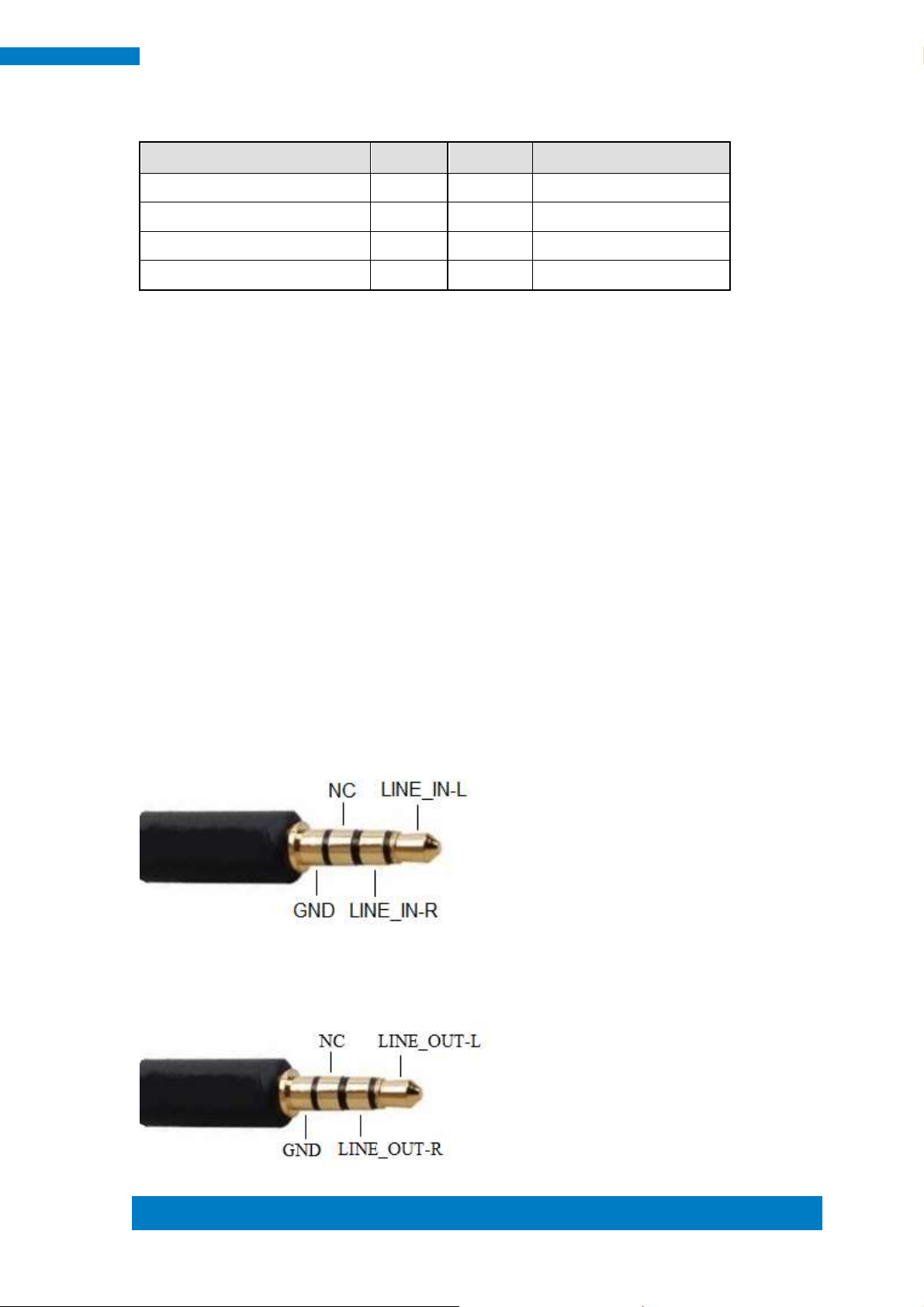
J10: Audio LINE_IN Connector
J11: Audio LINE_OUT Connector
Page 26

18
SI-12 User Manual
Warning:
It is strongly recommended that you avoid making any changes to
the chipset defaults. These defaults have been carefully chosen
by both AMI and your system manufacturer to provide the
absolute maximum performance and reliability. Changing the
defaults could cause the system to become unstable and crash in
some cases.
CHAPTER 3 BIOS SETUP
This chapter describes the different settings available in the AMI BIOS that comes
with the board. The topics covered in this chapter are as follows:
3.1 BIOS Introduction
The BIOS (Basic Input/Output System) installed in your computer system’s ROM
supports Intel processors. The BIOS provides critical low-level support for a standard
device such as disk drives, serial ports and parallel ports. It also password protection
as well as special support for detailed fine-tuning of the chipset controlling the entire
system.
3.2 BIOS Setup
The BIOS provides a Setup utility program for specifying the system configurations
and settings. The BIOS ROM of the system stores the Setup utility. When you turn on
the computer, the BIOS is immediately activated. Pressing the <Del> key immediately
allows you to enter the Setup utility. If you are a little bit late pressing the <Del> key,
POST (Power On Self Test) will continue with its test routines, thus preventing you
from invoking the Setup. If you still wish to enter Setup, restart the system by pressing
the ”Reset” button or simultaneously pressing the <Ctrl>, <Alt> and <Delete> keys.
You can also restart by turning the system Off and back On again. The following
message will appear on the screen:
Press <DEL> to Enter Setup
In general, you press the arrow keys to highlight items, <Enter> to select, the <PgUp>
and <PgDn> keys to change entries, <F1> for help and <Esc> to quit.
When you enter the Setup utility, the Main Menu screen will appear on the screen.
The Main Menu allows you to select from various setup functions and exit choices.
Page 27

Copyright © 2013 IBASE Technology Inc. All Rights Reserved.
19
IBASE Technology Inc.
Main Advanced Chipset Boot Security Save & Exit
Choose the system default
language
→ ← Select Screen
↑↓Select Item
Enter: Select
+- Change Field
F1: General Help
F2: Previous Values
F3: Optimized Default
F4: Save ESC: Exit
System Language
[English]
System Date
System Time
[Tue 01/20/2009]
[21:52:06]
Access Level
Administrator
Main Advanced Chipset Boot Security Save & Exit
OnBoard LAN PXE ROM [Disable]
► ACPI Settings
→ ← Select Screen
↑↓Select Item
Enter: Select
+- Change Field
F1: General Help
F2: Previous Values
F3: Optimized Default
F4: Save ESC: Exit
► iSmart Controller
► Super IO Configuration
► H/W Monitor
► CPU Configuration
► PPM Configuration
► IDE Configuration
Main Settings
Aptio Setup Utility – Copyright © 2013 American Megatrends, Inc.
System Language
Choose the system default language.
System Date
Set the Date. Use Tab to switch between Data elements.
System Time
Set the Time. Use Tab to switch between Data elements.
Advanced Settings
This section allows you to configure and improve your system and allows you to set up
some system features according to your preference.
Aptio Setup Utility – Copyright © 2013 American Megatrends, Inc.
Page 28

20
SI-12 User Manual
Main Advanced Chipset Boot Security Save & Exit
ACPI Settings
→ ← Select Screen
↑↓Select Item
Enter: Select
+- Change Field
F1: General Help
F2: Previous Values
F3: Optimized Default
F4: Save ESC: Exit
Enable Hibernation
Enabled
ACPI Sleep State
S3 (Suspend to RAM)
ACPI Settings
Aptio Setup Utility – Copyright © 2013 American Megatrends, Inc.
Enable Hibernation
Enables or Disables System ability to Hibernate (OS/S4 Sleep State). This option may be not
effective with some OS.
ACPI Sleep State
Select ACPI sleep state the system will enter when the SUSPEND button is pressed.
Page 29

Copyright © 2013 IBASE Technology Inc. All Rights Reserved.
21
IBASE Technology Inc.
Main Advanced Chipset Boot Security Save & Exit
iSMART Controller
→ ← Select Screen
↑↓Select Item
Enter: Select
+- Change Field
F1: General Help
F2: Previous Values
F3: Optimized Default
F4: Save ESC: Exit
Power-On after Power failure
Schedule Slot 1
Enable
None
Schedule Slot 2
None
iSmart Controller
Aptio Setup Utility – Copyright © 2013 American Megatrends, Inc.
Power-On after Power failure
This field sets the system power status whether Disable or Enable when power returns to the
system from a power failure situation.
Schedule Slot 1 / 2
Setup the hour/minute for system power on.
Page 30

22
SI-12 User Manual
Main Advanced Chipset Boot Security Save & Exit
Super IO Configuration
→ ← Select Screen
↑↓Select Item
Enter: Select
+- Change Field
F1: General Help
F2: Previous Values
F3: Optimized Default
F4: Save ESC: Exit
► Eup/Erp standby power control
Keep standby power
► Serial Port 1 Configuration
Super IO Configuration
Aptio Setup Utility – Copyright © 2013 American Megatrends, Inc
Eup/Erp standby power control
Eup/Erp control on S5
[Keep Standby power] Enable all of the standby power and ignore Eup/Erp specification.
[Ethernet only [WOL] Only provide the standby power for Ethernet chip.
[NO standby power] Shutdown all of the standby power.
Serial Port 1 Configuration
Set parameters of serial port 1(COMA)
Page 31

Copyright © 2013 IBASE Technology Inc. All Rights Reserved.
23
IBASE Technology Inc.
Main Advanced Chipset Boot Security Save & Exit
PC Health Status
→ ← Select Screen
↑↓Select Item
Enter: Select
+- Change Field
F1: General Help
F2: Previous Values
F3: Optimized Default
F4: Save ESC: Exit
SYS temp
+33.0 C
CPU temp
+34.5 C
Vcore
+1.704 V
+1.35V
+1.544 V
AVCC
+3.360 V
VCC3V
+3.328 V
CPU Shutdown Temperature
Disabled
H/W Monitor
Aptio Setup Utility – Copyright © 2013 American Megatrends, Inc.
Shutdown Temperature
This field enables or disables the Shutdown Temperature
Disabled (default)
70 ℃/158 F
75 ℃/167 F
80 ℃/176 F
85 ℃/185 F
90 ℃/194 F
95 ℃/203 F
Temperatures/Voltages
These fields are the parameters of the hardware monitoring function feature of the
motherboard. The values are read-only values as monitored by the system and show the PC
health status
Page 32

24
SI-12 User Manual
Main Advanced Chipset Boot Security Save & Exit
CPU Configuration
►Socket 0 CPU Information
→ ← Select Screen
↑↓Select Item
Enter: Select
+- Change Field
F1: General Help
F2: Previous Values
F3: Optimized Default
F4: Save ESC: Exit
CPU Speed
1918 Mhz
64-bit
Supported
CPU Configuration
This section shows the CPU configuration parameters.
Aptio Setup Utility – Copyright © 2013 American Megatrends, Inc.
Socket 0 CPU Information
Socket specific CPU Information.
Page 33

Copyright © 2013 IBASE Technology Inc. All Rights Reserved.
25
IBASE Technology Inc.
Main Advanced Chipset Boot Security Save & Exit
CPU PPM Configuration
→ ← Select Screen
↑↓Select Item
Enter: Select
+- Change Field
F1: General Help
F2: Previous Values
F3: Optimized Default
F4: Save ESC: Exit
EIST
Enabled
CPU PPM Configuration
Aptio Setup Utility – Copyright © 2013 American Megatrends, Inc.
EIST
Enable/Disable Intel SpeedStep.
Page 34

26
SI-12 User Manual
Main Advanced Chipset Boot Security Save & Exit
IDE Configuration
→ ← Select Screen
↑↓Select Item
Enter: Select
+- Change Field
F1: General Help
F2: Previous Values
F3: Optimized Default
F4: Save ESC: Exit
Serial-ATA (SATA)
SATA Speed Support
Enabled
[Gen2]
SATA Mode
AHCI Mode
Serial-ATA Port 0
Enabled
SATA Port0
Not Present
SATA Port1
InnoDisk Corp. (32.0GB)
IDE Configuration
SATA Devices Configuration.
Aptio Setup Utility – Copyright © 2013 American Megatrends, Inc.
Serial-ATA(SATA)
Enabled / Disabled Serial ATA
SATA Mode
Select IDE / AHCI Mode
Serial –ATA Port 0
Enabled / Disabled Serial Port 0
Page 35

Copyright © 2013 IBASE Technology Inc. All Rights Reserved.
27
IBASE Technology Inc.
Main Advanced Chipset Boot Security Save & Exit
→ ← Select Screen
↑↓Select Item
Enter: Select
+- Change Field
F1: General Help
F2: Previous Values
F3: Optimized Default
F4: Save ESC: Exit
► North Bridge
Main Advanced Chipset Boot Security Save & Exit
→ ← Select Screen
↑↓Select Item
Enter: Select
+- Change Field
F1: General Help
F2: Previous Values
F3: Optimized Default
F4: Save ESC: Exit
Memory Information
Total Memory
4096 MB (LPDDR3)
Memory Slot0
4096 MB (LPDDR3)
Memory Slot2
Not Present
Chipset Settings
Aptio Setup Utility – Copyright © 2013 American Megatrends, Inc.
North Bridge
Aptio Setup Utility – Copyright © 2013 American Megatrends, Inc.
Page 36

28
SI-12 User Manual
Main Advanced Chipset Boot Security Save & Exit
Boot Configuration
→ ← Select Screen
↑↓Select Item
Enter: Select
+- Change Field
F1: General Help
F2: Previous Values
F3: Optimized Default
F4: Save ESC: Exit
Setup Prompt Timeout
1
Bootup NumLock State
On
Quiet Boot
Disabled
Fast Boot
Disabled
Boot Option Priorities
Boot Option #1
UEFI:Built-in EFI
Boot Settings
This section allows you to configure the boot settings.
Aptio Setup Utility – Copyright © 2013 American Megatrends, Inc.
Setup Prompt Timeout
Number of seconds to wait for setup activation key.
65535(0xFFFF) means indefinite waiting.
Bootup NumLock State
Select the keyboard NumLock state.
Quiet Boot
Enables or disables Quiet Boot option.
Fast Boot
Enables or disables boot with initialization of a minimal set of devices required to launch
active boot option. Has no effect for BBS boot options.
Boot Option Priorities
Sets the system boot order.
Page 37

Copyright © 2013 IBASE Technology Inc. All Rights Reserved.
29
IBASE Technology Inc.
[
REMARKS:
Before the installation of Windows 8, go to the BIOS Setup to check that the Boot Option
#1 of the Boot Option Priorities field is set as UEFI MODE (DVD drive).
Page 38

30
SI-12 User Manual
Main Advanced Chipset Boot Security Save & Exit
Password Description
→ ← Select Screen
↑↓Select Item
Enter: Select
+- Change Field
F1: General Help
F2: Previous Values
F3: Optimized Default
F4: Save ESC: Exit
If ONLY the Administrator’s password is set, then this
only limit access to Setup and is only asked for when
entering Setup.
If ONLY the User’s password is set, then this is a
power on password and must be entered to boot or
enter Setup. In Setup the User will have Administrator
rights
The password length must be
in the following range:
Minimum length
3
Maximum length
20
Administrator Password
User Password
HDD Security Configuration:
P1:InnoDisk Cor
Security Settings
This section allows you to configure and improve your system and allows you to set
up some system features according to your preference.
Aptio Setup Utility – Copyright © 2013 American Megatrends, Inc.
Administrator Password
Set Administrator Password.
Page 39

Copyright © 2013 IBASE Technology Inc. All Rights Reserved.
31
IBASE Technology Inc.
Main Advanced Chipset Boot Security Save & Exit
Save Changes and Exit
→ ← Select Screen
↑↓Select Item
Enter: Select
+- Change Field
F1: General Help
F2: Previous Values
F3: Optimized Default
F4: Save ESC: Exit
Discard Changes and Exit
Save Changes and Reset
Discard Changes and Reset
Save Options
Save Changes
Discard Changes
Restore Defaults
Save as User Defaults
Restore User Defaults
Boot Override
Save & Exit Settings
Aptio Setup Utility – Copyright © 2013 American Megatrends, Inc.
Save Changes and Exit
Exit system setup after saving the changes.
Discard Changes and Exit
Exit system setup without saving any changes.
Save Changes and Reset
Reset the system after saving the changes.
Discard Changes and Reset
Reset system setup without saving any changes.
Save Changes
Save Changes done so far to any of the setup options.
Discard Changes
Discard Changes done so far to any of the setup options.
Restore Defaults
Restore/Load Defaults values for all the setup options.
Save as User Defaults
Save the changes done so far as User Defaults.
Restore User Defaults
Restore the User Defaults to all the setup options.
Page 40

32
SI-12 User Manual
CHAPTER 4 DRIVERS INSTALLATION
This section describes the installation procedures for software and drivers. The
software and drivers are included with the motherboard. If you find the items missing,
please contact the vendor where you made the purchase
IMPORTANT NOTE:
After installing your Windows operating system, you must install first the Intel Chipset
Software Installation Utility before proceeding with the drivers installation.
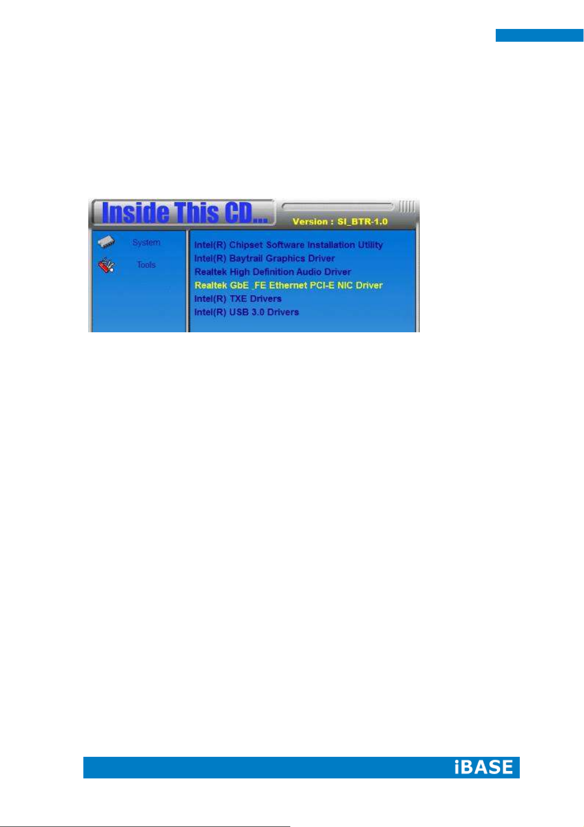
4.1 Intel Chipset Software Installation Utility
1. Insert the DVD that comes with the board. Click Intel and then Intel(R) Baytrail
Chipset. Click Intel(R) Chipset Software Installation Utility.
3. When the Welcome screen to the Intel® Chipset Device Software appears, click
Next to continue.
4. Click Yes to accept the software license agreement and proceed with the
installation process.
5. The Setup process is now complete. Click Finish to restart the computer and for
changes to take effect.
Page 41

Copyright © 2013 IBASE Technology Inc. All Rights Reserved.
33
IBASE Technology Inc.
4.2 VGA Drivers Installation
1. Insert the DVD that comes with the board. Click Intel and then Intel(R) Baytrail Chipset. Click
Intel(R) Baytrail Graphics Driver.
2. When the Welcome screen appears, click Next to continue.
3. Click Yes to accept the license agreement and continue the installation.
4. Setup complete. Click Finish to restart the computer and for changes to take effect.
Page 42

34
SI-12 User Manual
4.3 Realtek High Definition Audio Driver Installation
1. Insert the DVD that comes with the board. Click Intel and then Intel(R) Baytrail
Chipset. Click Realtek High Definition Audio Driver.
2. On the Welcome screen, click Next to proceed with the installation.
3. InstallShield Wizard is complete. Click Finish to restart the computer and for
changes to take effect.
Page 43

Copyright © 2013 IBASE Technology Inc. All Rights Reserved.
35
IBASE Technology Inc.
4.4 Intel Trusted Execution Engine Installation
1. Insert the DVD that comes with the board. Click Intel and then Intel(R) Baytrail
Chipset. Click Intel(R) Baytrail Graphics Driver.
2. On the Setup Welcome screen, click Next to proceed with the installation process.
3. Click Next accept the license agreement and continue the installation.
4. Installation of the Intel Trusted Execution Engine is now complete. Click Finish.
Page 44
36
SI-12 User Manual
4.5 LAN Drivers Installation
1. Insert the CD that comes with the board.
2. Click LAN Card and then Realtek Realtek GbE-FE Ethernet PCI-E NIC Controller
Drivers.
3. In the Welcome screen, click Next.
4. In the License Agreement screen, click I accept the terms in license agreement
and Next to accept the software license agreement and proceed with the installation
process.
5. Click the checkbox for Drivers in the Setup Options screen to select it and click
Next to continue.
6. When the Ready to Install the Program screen appears, click Install to continue.
7. When InstallShield Wizard is complete, click Finish.
Page 45
Copyright © 2013 IBASE Technology Inc. All Rights Reserved.
37
IBASE Technology Inc.
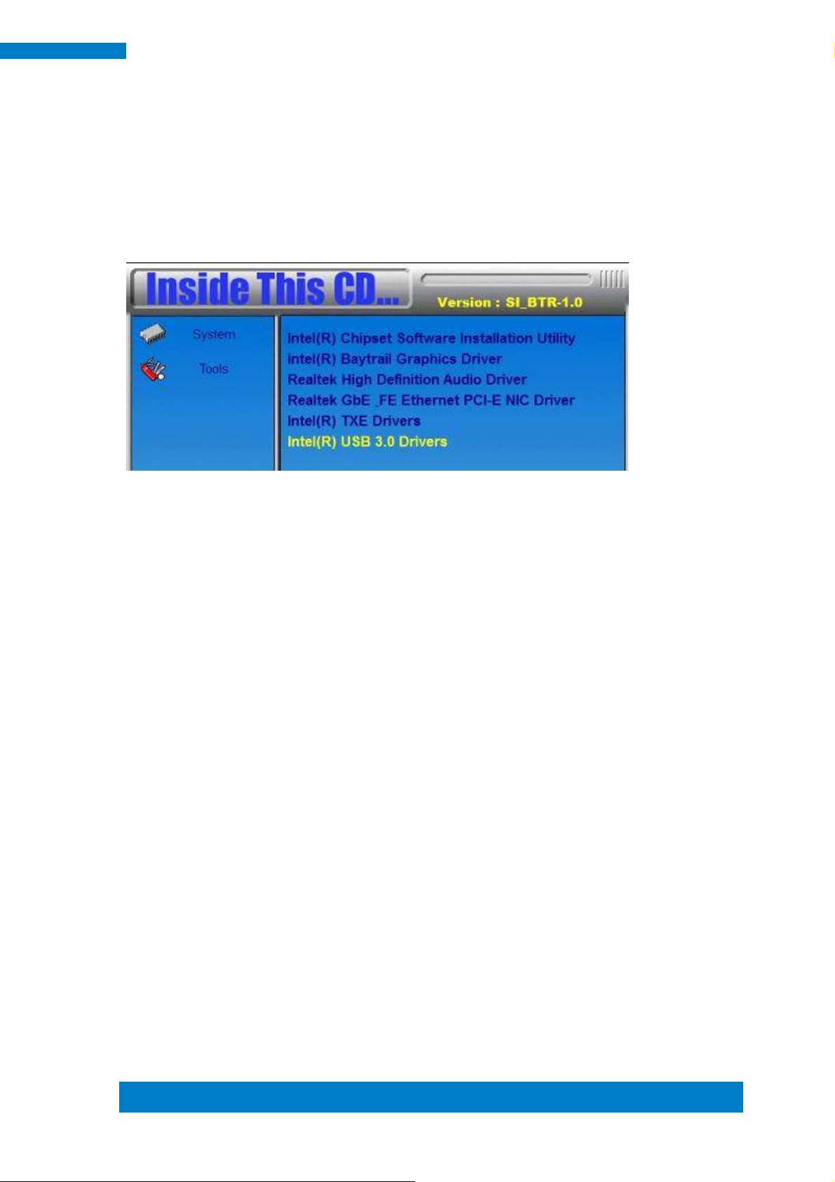
4.6 Intel® USB 3.0 Drivers
1. Insert the CD that comes with the board. Click Intel and then Intel(R) USB3.0
Drivers.
2. Click Intel(R) USB 3.0 Drivers.
3. When the Welcome screen to the InstallShield Wizard for Intel® USB 3.0
eXtensible Host Controller Driver, click Next.
4. Click Yes to to agree with the license agreement and continue the installation.
5. On the Readme File Information screen, click Next to continue the installation of
the Intel® USB 3.0 eXtensible Host Controller Driver.
6. Setup complete. Click Finish to restart the computer and for changes to take
effect.
Page 46

38
SI-12 User Manual
Appendix
Mounting SI-12 to the Wall
You can install SI-12 on plastic (LCD monitor), wood, drywall surface over studs, or
a solid concrete or metal plane directly. Ensure the installer uses at least two M3
length 6mm screws to secure the system on the wall. Two M3 length 6mm screws
are recommended to secure the system onto the wall.
Fasteners are not included with the unit, and must be supplied by the installer. The
types of fasteners required are dependent on the type of wall construction. Choose
fasteners that are rated either ”Medium Duty“ or ”Heavy Duty.“ To assure proper
fastener selection and installation, follow the fastener manufacturer’s
recommendations.
Page 47

Copyright © 2013 IBASE Technology Inc. All Rights Reserved.
39
IBASE Technology Inc.
Wall Mounting Requirements
Note: Before mounting the system onto the wall, ensure that you are following all
applicable building and electric codes.
When mounting, ensure that you have enough room for power and signal cable
routing and have good ventilation for power adapter. The method of mounting must
be able to support the weight of SI-12 plus the suspend weight of all the cables to
be attached to the system. Use the following methods for mounting your system:
Mounting to hollow walls
Method 1: Wood surface – A minimum wood thickness – 38mm (1.5in.) by
25.4 cm (10in.) – of high, construction – grade wood is recommended.
Note: This method provides the most reliable attachment of the unit with
little risk that the unit will come loose or require ongoing maintenance.
Method 2: Drywall walls - Drywall over wood studs is acceptable.
Mounting to a solid concrete or brick wall - Mounts on a flat smooth surface.
Selecting the Location
Plan the mounting location thoroughly. Locations such as walkway areas, hallways,
and crowded areas are not recommended. Mount the unit to a flat, sturdy,
structurally sound column or wall surface.
The best mounting surface is a standard countertop, cabinet, table, or other
structure that is minimally the width and length of the unit. This recommendation
reduces the risk that someone may accidentally walk into and damage the device.
Local laws governing the safety of individuals might require this type of
consideration.
Page 48

40
SI-12 User Manual
SI-12 Mounting Bracket Solution
SI-12 mounting bracket (IBASE) part number: SC2SIMK1---0A1100P
Install SI-12 to the mounting bracket using 2 screws, as shown in the picture.
 Loading...