

Page 1

SI-06 Series
User Manual
Page 2

Revision
Release Date
V0.1
2013/04/11
V0.2
2014/09/23
Page 3

Copyright © 2013 IBASE Technology INC. All Rights Reserved.
No part of this manual, including the products and software described in it, may be
reproduced, transmitted, transcribed, stored in a retrieval system, or translated into
any language in any form or by any means, except documentation kept by the
purchaser for backup purposes, without the express written permission of IBASE
Technology INC. (“IBASE”).
Products and corporate names mentioned in this manual may or may not be
registered trademarks or copyrights of their respective companies, and are used for
identification purposes only. All trademarks are the property of their respective
owners.
Every effort has been made to ensure that the contents of this manual are correct and
up to date. However, the manufacturer makes no guarantee regarding the accuracy of
its contents, and reserves the right to make changes without prior notice.
3
Page 4

Table of Contents
Setting up your system ........................................................................................................ 5
Care during use .................................................................................................................... 6
Acknowledgments ............................................................................................................... 7
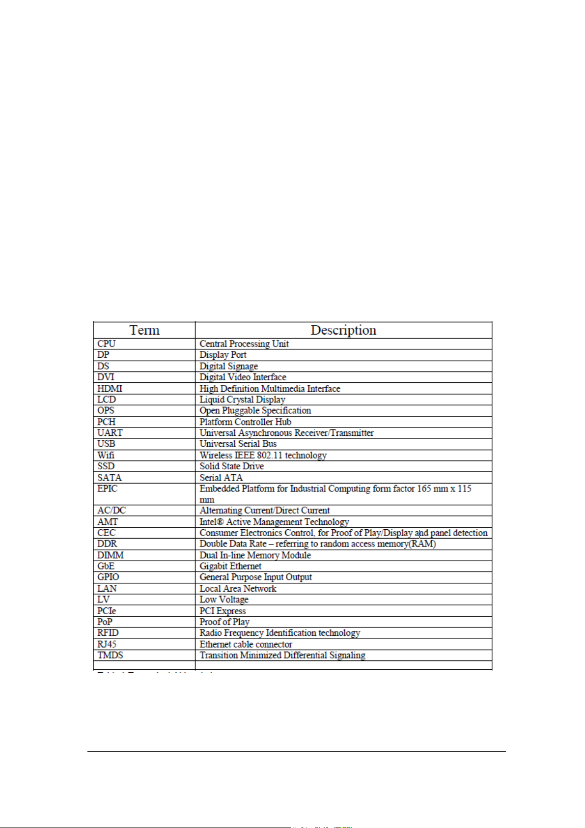
Table: Terms and Abbreviation ............................................................................................ 7
Accessories ............................................................................................................. 8
Components ........................................................................................................... 8
I/O View ............................................................................................................................... 8
System Specification ..............................................................................................10
Mechanical Specification .......................................................................................11
SI-06 Mounting Bracket Solution ....................................................................................... 12
SI-06 VESA Mounting Solution ........................................................................................... 13
Exploded View of the SI-06 Assembly ............................................................................... 14
Parts Description ................................................................................................................ 14
Installation ............................................................................................................14
Installing the memory........................................................................................................ 15
Jumper Locations on IB901 ................................................................................................ 16
Connector Locations on IB901 ........................................................................................... 17
BIOS Setup ............................................................................................................20
Drivers Installation ................................................................................................35
Appendix ...............................................................................................................39
4
Page 5

Safety Information
Your SI-06 is designed and tested to meet the latest standards of safety for
information technology equipment. However, to ensure your safety, it is important that
you read the following safety instructions.
Setting up your system
Read and follow all instructions in the documentation before you operate your
system.
Do not use this product near water.
Set up the system on a stable surface. Do not secure the system on any unstable
plane.
Do not place this product on an unstable cart, stand, or table. The product may
fall, causing serious damage to the product.
Slots and openings on the chassis are for ventilation. Do not block or cover these
openings. Make sure you leave plenty of space around the system for ventilation.
Never insert objects of any kind into the ventilation openings.
This system should be operated from the type of power indicated on the marking
label. If you are not sure of the type of power available, consult your dealer or
local power company.
Use this product in environments with ambient temperatures between 0˚C and
45˚C.
If you use an extension cord, make sure that the total ampere rating of the
devices plugged into the extension cord does not exceed its ampere rating.
DO NOT LEAVE THIS EQUIPMENT IN AN ENVIRONMENT WHERE
THESTORAGE TEMPERATURE MAY GO BELOW -20° C (-4° F) OR ABOVE
80° C (176° F). THIS COULD DAMAGE THE EQUIPMENT. THE EQUIPMENT
SHOULD BE IN A CONTROLLED ENVIRONMENT.
5
Page 6

Care during use
Do not walk on the power cord or allow anything to rest on it.
Do not spill water or any other liquids on your system.
When the system is turned off, a small amount of electrical current still flows.
Always unplug all power, and network cables from the power outlets before
cleaning the system.
If you encounter the following technical problems with the product, unplug the
power cord and contact a qualified service technician or your retailer.
The power cord or plug is damaged.
Liquid has been spilled into the system.
The system does not function properly even if you follow the operating
instructions.
The system was dropped or the cabinet is damaged.
Lithium-Ion Battery Warning
CAUTION: Danger of explosion if battery is incorrectly replaced. Replace only with
the same or equivalent type recommended by the manufacturer. Dispose of used
batteries according to the manufacturer’s instructions.
NO DISASSEMBLY
The warranty does not apply to the products that have been disassembled by users
WARNING
HAZARDOUS MOVING PARTS
KEEP FINGERS AND OTHER BODY PARTS AWAY
6
Page 7
Acknowledgments
AMI is a registered trademark of AMI Software International, Inc.
Intel are registered trademarks of Intel Corporation.
Microsoft Windows is a registered trademark of Microsoft Corporation.
FINTEK is a registered trademark of FINTEK Electronics Corporation.
REALTEK is a registered trademark of REALTEK Electronics Corporation.
All other product names or trademarks are properties of their respective owners.
Table: Terms and Abbreviation
7
Page 8
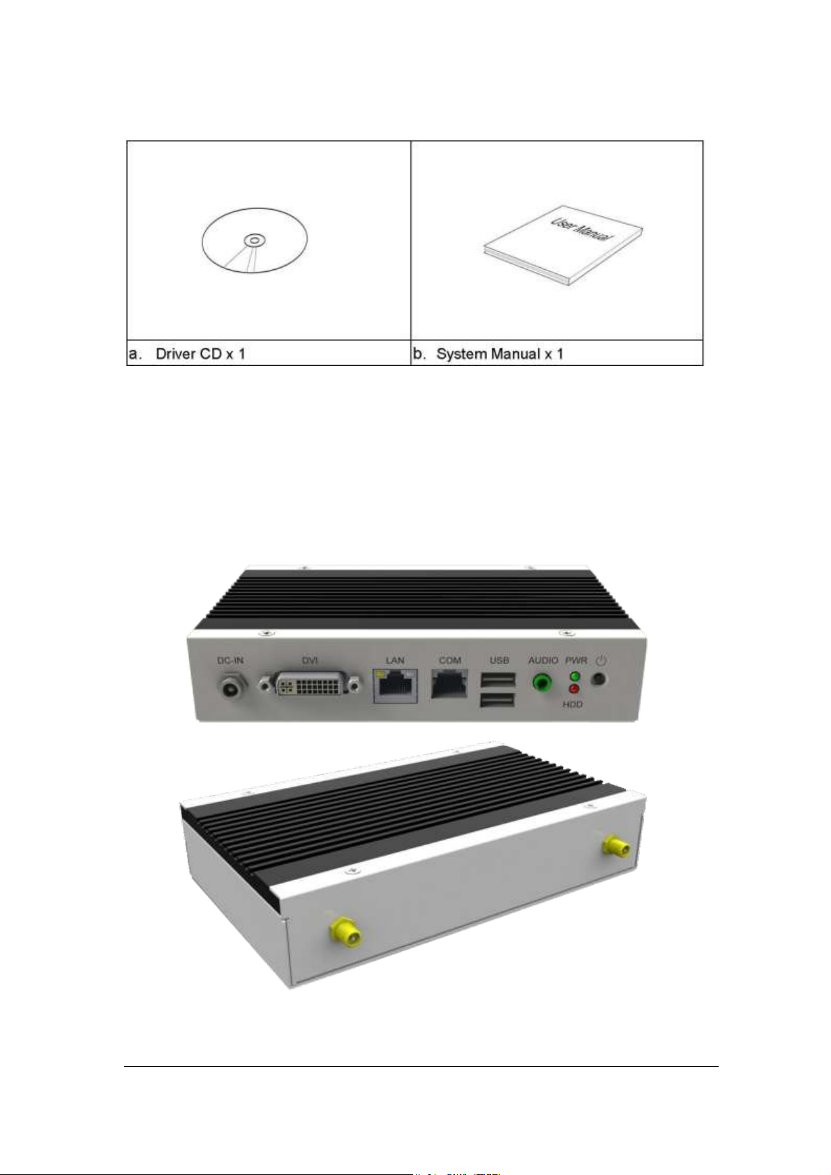
Accessories
Components
I/O View
Refer to the diagram below to identify the components on this side of the system.
8
Page 9

Power Button
The power switch allows powering ON and OFF the system.
HDD
The hard disk LED blinks when data is being written into or read from the hard
disk.
Power
The power bottom LED illuminated when system been power on.
DVI-I Port
The DVI-I interface is to transmitting uncompressed digital data.
LAN 1
The eight-pin RJ-45 LAN port supports a standard Ethernet cable for connection
to a local network.
USB1/2
The USB (Universal Serial Bus 2.0) port is compatible with USB devices such as
keyboards, mouse devices, cameras, and hard disk drives. USB allows many
devices to run simultaneously on a single computer, with some peripheral acting
as additional plug-in sites or hubs.
COM 1
Communication or serial port is compatible with RJ 45 interface without RI (ring
indicator) signal.
AUDIO
The stereo audio jack (3.5mm) is used to connect the system’s audio out signal to
amplified speakers or headphones.
DC-IN 12 V
The supplied power adapter converts AC power to DC power for use with this
jack. Power supplied through this jack supplies power to the system. To prevent
damage to the system, always use the supplied power adapter.
9
Page 10
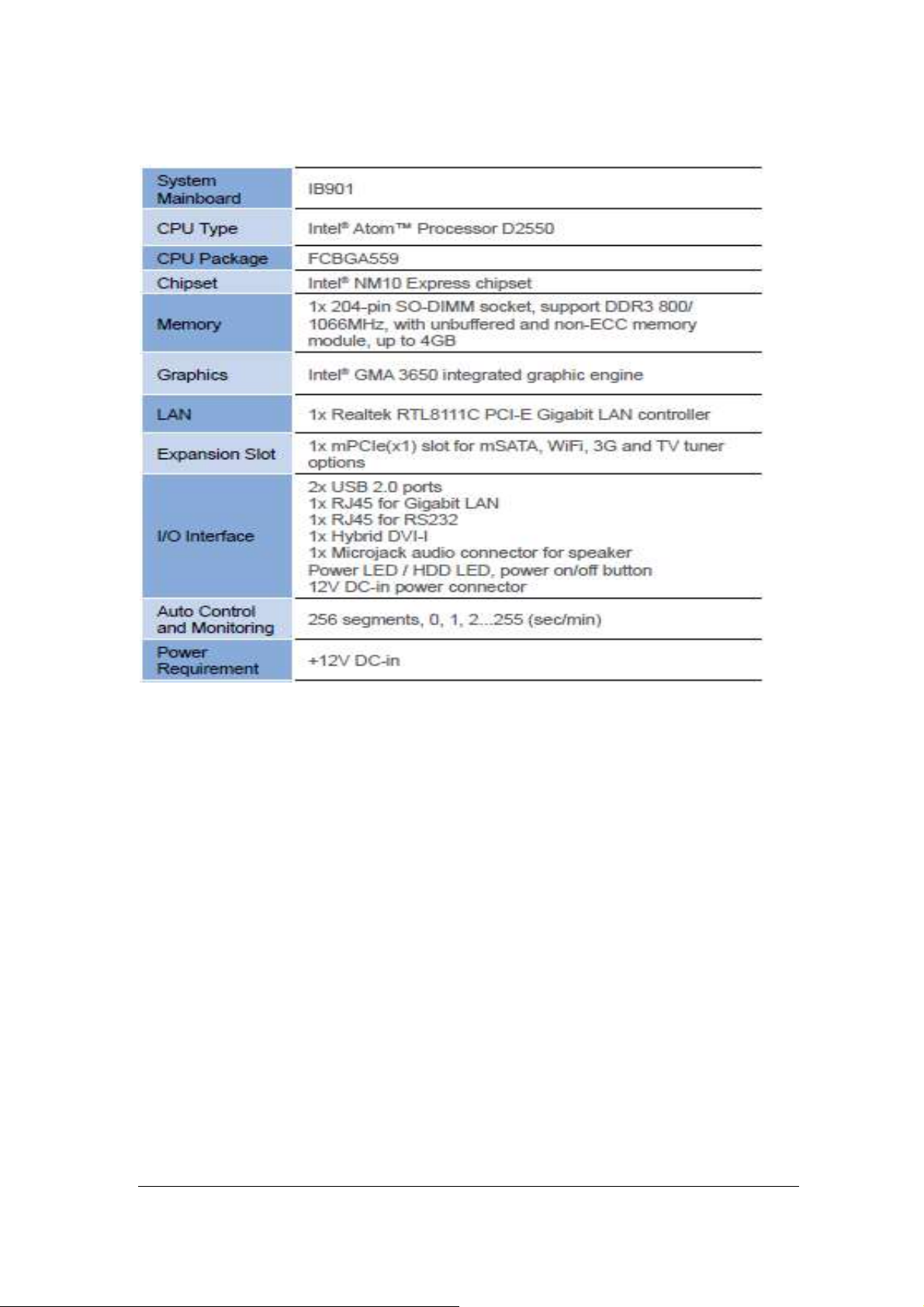
System Specifications
‧
This specification is subject to change without prior notice.
10
Page 11
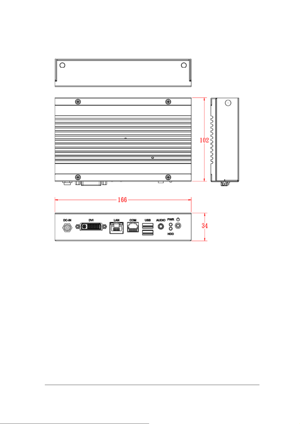
Mechanical Specification
11
Page 12
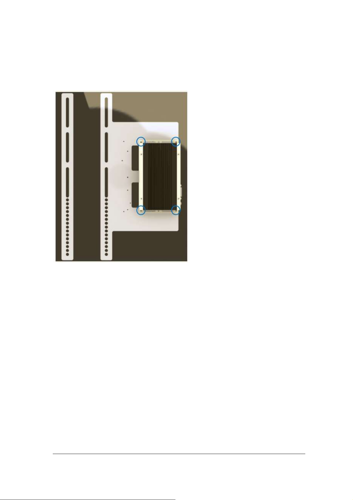
SI-06 Mounting Bracket Solution
SI-06 mounting bracket (IBASE) part number: SC2SIMK1---0A1100P
Install SI-06 to the mounting bracket using 4 screws, as shown in the picture.
12
Page 13
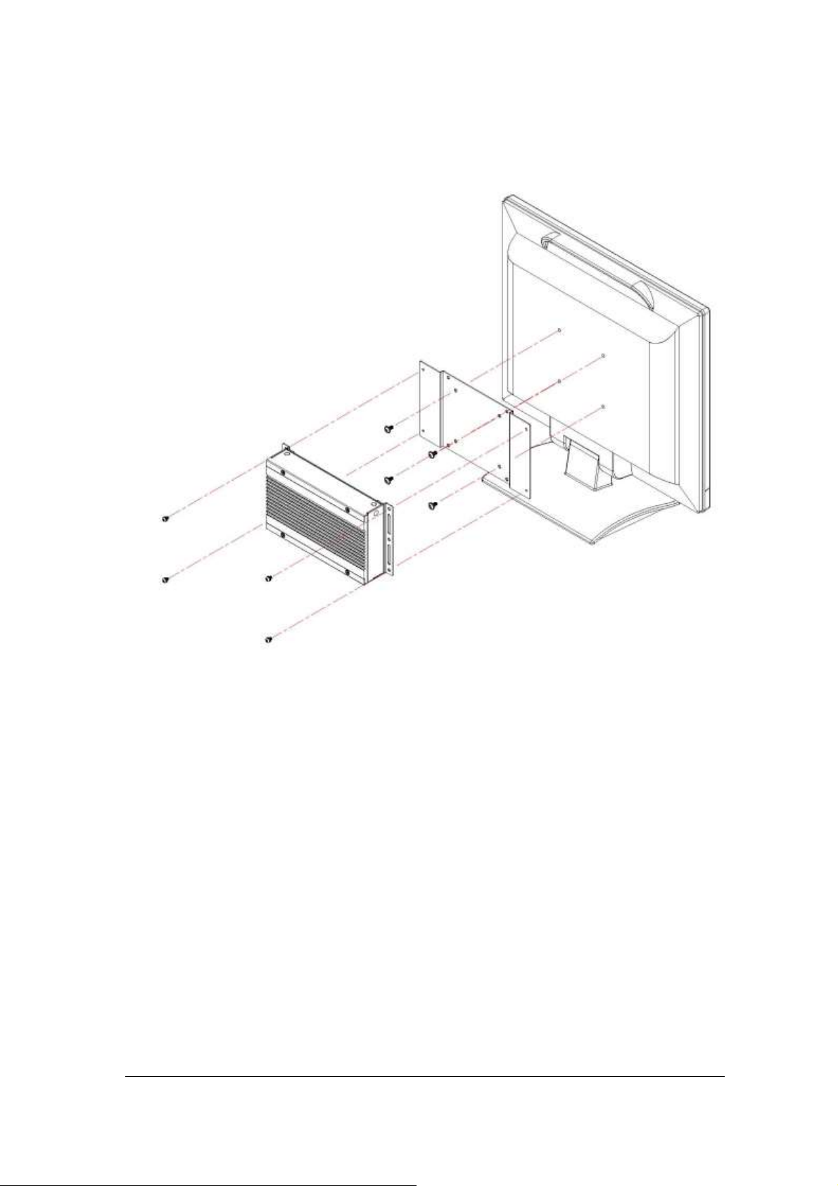
SI-06 VESA Mounting Solution
You can install SI-06 on plastic (LCD monitor), wood, drywall surface over studs, or
a solid concrete or metal plane directly. Ensure the installer uses at least four M3
length 6mm screws to secure the system on wall. Six M3 length 6mm screws are
recommended to secure the system on wall.
13
Page 14

Exploded View of the SI-06 Assembly
Part No.
Description
Part No.
Description
1
Top cover
2
Main chassis
3
Rear panel
4
SI-06 MB
5
HDD holder
6
2.5” HDD
7
Brackets
Parts Description
Installation
14
Page 15

Installing the memory
The IB901 board supports two DDR3 memory socket for a maximum total memory of
16GB in DDR3 SO-DIMM memory type. Installing and Removing Memory Modules
To install the DDR3 modules, locate the memory slot on the board and perform the
following steps:
1. Hold the DDR3 module so that the key of the DDR3 module aligns with that on
the memory slot. Insert the module into the socket at a slight angle
(approximately 30 degrees). Note that the socket and module are both keyed,
which means that the module can be installed only in one direction.
2. To seat the memory module into the socket, apply firm and even pressure to
each end of the module until you feel it slip down into the socket.
3. With the module properly seated in the socket, rotate the module downward.
Continue pressing downward until the clips at each end lock into position.
4. To remove the DDR3 module, press the clips with both hands.
15
Page 16

Setting the Jumpers
The following lists the connectors on IB901 and their respective functions.
Jumper Locations on IB901
16
Page 17

J3: Clear CMOS Contents
J3
Setting
Function
Pin 1-2
Short/Closed
Normal
Pin 2-3
Short/Closed
Clear CMOS
Connector Locations on IB901
Top Side
Bottom Side
17
Page 18

SW1: Power Switch
CN5
Pin #
Signal Name
1
DSR, Data set ready
2
GND, ground
3
GND, ground
4
TXD, Transmit data
5
RXD, Receive data
6
DCD, Data carrier detect
7
DTR, Data terminal ready
8
CTS, Clear to send
9
RTS, Request to send
10
RI, Ring indicator
CN1: 3G SIM Card Slot
CN2: SATA 2.5” HDD/SSD Connector
CN4: Gigabit LAN Connector (Realtek RTL8111E)
This RJ45 LAN connector features LAN wakeup.
CN5: COM Serial Port
CN6: USB2.0 Connector
CN7: Audio Connector (Headphone out)
18
Page 19

CN8: DVI-I Connector
Signal Name
Pin #
Pin #
Signal Name
DATA 2-
1
16
HOT POWER
DATA 2+
2
17
DATA 0-
Shield 2/4
3
18
DATA 0+
DATA 4-
4
19
SHIELD 0/5
DATA 4+
5
20
DATA 5-
DDC CLOCK
6
21
DATA 5+
DDC DATA
7
22
SHIELD CLK
VSYNC
8
23
CLOCK -
DATA 1-
9
24
CLOCK +
DATA 1+
10
C1
Red.
SHIELD 1/3
11
C2
Green
DATA 3-
12
C3
Blue
DATA 3+
13
C4
HSYNC
DDC POWER
14
C5
Ground
A GROUND 1
15
C6
Ground
CRT via DVI-I connector
J2: SPI Flash (Factory use only)
J4: DDR3 SO-DIMM Socket
J6: Mini PCIE Connector
Supports mSATA and 3G SIM card
J7: SATA PWR Connector
J9: +12V DC-IN Connector
19
Page 20

BIOS Setup
Warning:
It is strongly recommended that you avoid making any changes to the
chipset defaults. These defaults have been carefully chosen by both
AMI and your system manufacturer to provide the absolute maximum
performance and reliability. Changing the defaults could cause the
system to become unstable and crash in some cases.
BIOS Introduction
The BIOS (Basic Input/Output System) installed in your computer system’s ROM
supports Intel processors. The BIOS provides critical low-level support for a standard
device such as disk drives, serial ports and parallel ports. It also password protection
as well as special support for detailed fine-tuning of the chipset controlling the entire
system.
BIOS Setup
The BIOS provides a Setup utility program for specifying the system configurations
and settings. The BIOS ROM of the system stores the Setup utility. When you turn on
the computer, the BIOS is immediately activated. Pressing the <Del> key immediately
allows you to enter the Setup utility. If you are a little bit late pressing the <Del> key,
POST (Power On Self Test) will continue with its test routines, thus preventing you
from invoking the Setup. If you still wish to enter Setup, restart the system by pressing
the ”Reset” button or simultaneously pressing the <Ctrl>, <Alt> and <Delete> keys.
You can also restart by turning the system Off and back On again. The following
message will appear on the screen:
Press <DEL> to Enter Setup
In general, you press the arrow keys to highlight items, <Enter> to select, the <PgUp>
and <PgDn> keys to change entries, <F1> for help and <Esc> to quit.
When you enter the Setup utility, the Main Menu screen will appear on the screen.
The Main Menu allows you to select from various setup functions and exit choices.
System Date
Set the Date. Use Tab to switch between Data elements.
System Time
Set the Time. Use Tab to switch between Data elements.
20
Page 21

Advanced Settings
Main Advanced Chipset Boot Security Save & Exit
Legacy OpROM Support
→ ← Select Screen
↑↓ Select Item
Enter: Select
+- Change Opt
F1: General Help
F2: Previous Values
F3: Optimized Default
F4: Save & Exit ESC: Exit
Launch PXE OpROM
Disabled
► PCI Subsystem Settings
► ACPI Settings
► Wake up event setting
► CPU Configuration
► iSmart Configuration
► IDE Configuration
► USB Configuration
► Super IO Configuration
► H/W Monitor
This section allows you to configure and improve your system and allows you to set
up some system features according to your preference.
Aptio Setup Utility
Launch PXE OpROM
Enable or Disable Boot Option for Legacy Network Devices.
21
Page 22

PCI Subsystem Settings
Main Advanced Chipset Boot Security Save & Exit
PCI Bus Driver Version V 2.05.01
→ ←→ ← Select Screen
↑↓ Select Item
Enter: Select
+- Change Opt
F1: General Help
F2: Previous Values
F3: Optimized Default
F4: Save & Exit ESC: Exit
PCI ROM Priority
Legacy ROM
PCI Common Settings
PCI Latency Timer
32 PCI Bus Clocks
VGA Palette Snoop
Disabled
PERR# Generation
Disabled
SERR# Generation
Disabled
Aptio Setup Utility
PCI ROM Priority
In case of multiple Option ROMs (Legacy and EFI Compatible), specifies what PCI
Option ROM to launch.
PCI Latency Timer
Value to be programmed into PCI Latency Timer Register.
VGA Palette Snoop
Enables or Disables VGA Palette Registers Snooping.
PERR# Generation
Enables or Disables PCI Device to Generate PERR#.
SERR# Generation
Enables or Disables PCI Device to Generate SERR#.
22
Page 23

ACPI Settings
Main Advanced Chipset Boot Security Save & Exit
ACPI Settings
Enable ACPI Auto Configuration Disabled
→ ← Select Screen
↑↓ Select Item
Enter: Select
+- Change Opt
F1: General Help
F2: Previous Values
F3: Optimized Default
F4: Save & Exit ESC: Exit
Enable Hibernation
Enabled
ACPI Sleep State
S1 (CPU Stop Clock)
S3 Video Repost
Disabled
Main Advanced Chipset Boot Security Save & Exit
→ ← Select Screen
↑↓ Select Item
Enter: Select
+- Change Opt
F1: General Help
F2: Previous Values
F3: Optimized Default
F4: Save & Exit ESC: Exit
Wake on Ring
Disabled
Wake on PCIE PME
Disabled
Aptio Setup Utility
Enabled ACPI Auto Configuration
Enables or Disables BIOS ACPI Auto Configuration.
Enable Hibernation
Enables or Disables System ability to Hibernate (OS/S4 Sleep State). This option may
be not effective with some OS.
ACPI Sleep State
Select the highest ACPI sleep state the system will enter when the SUSPEND button
is pressed.
Enabled ACPI Auto Configuration
Enable or Disable S3 Video Repost.
Wake up event setting
Aptio Setup Utility
Wake on Ring
The options are Disabled and Enabled.
Wake on PCIE PME
The options are Disabled and Enabled.
23
Page 24

CPU Configuration
Main Advanced Chipset Boot Security Save & Exit
CPU Configuration
→ ← Select Screen
↑↓ Select Item
Enter: Select
+- Change Opt
F1: General Help
F2: Previous Values
F3: Optimized Default
F4: Save & Exit ESC: Exit
Processor Type
Intel(R) Atom(TM) CPU
EMT64
Supported
Processor Speed
1865 MHz
System Bus Speed
533 MHz
Ratio Status
14
Actual Ratio
14
System Bus Speed
533 MHz
Processor Stepping
30661
Microcode Revision
269
L1 Cache RAM
2x56 k
L2 Cache RAM
2x512 k
Processor Core
Dual
Hyper-Threading
Supported
Hyper-Threading
Enabled
Execute Disable Bit
Enabled
Limit CPUID Maximum
Disabled
This section shows the CPU configuration parameters.
Aptio Setup Utility
Hyper-threading
Enabled for Windows XP and Linux (OS optimized for Hyper-Threading Technology)
and Disabled for other OS (OS not optimized for Hyper-Threading Technology). When
Disabled, only one thread per enabled core is enabled.
Execute Disable Bit
XD can prevent certain classes of malicious buffer overflow attacks when combined
with a supporting OS (Windows Server 2003 SP1, Windows XP SP2, SuSE Linux 9.2,
Re33dHat Enterprise 3 Update 3.)
Limit CPUID Maximum
Disabled for Windows XP.
24
Page 25

iSmart Controller
Main Advanced Chipset Boot Security Save & Exit
iSmart Controller
→ ← Select Screen
↑↓ Select Item
Enter: Select
+- Change Opt
F1: General Help
F2: Previous Values
F3: Optimized Default
F4: Save & Exit ESC: Exit
Power-On after Power failure
Enable
Schedule Slot 1
None
Schedule Slot 2
None
Main Advanced Chipset Boot Security Save & Exit
→ ← Select Screen
↑↓ Select Item
Enter: Select
+- Change Opt
F1: General Help
F2: Previous Values
F3: Optimized Default
F4: Save & Exit ESC: Exit
SATA Port0
Not Present
SATA Port1
Not Present
SATA Controller(s)
Enabled
Configure SATA as
IDE
Aptio Setup Utility
Power-On after Power failure
This field sets the system power status whether on or off when power returns to the
system from a power failure situation.
Schedule Slot
None / Power On / Power On/Off – Setup the hour/minute for system power on.
IDE Configuration
Aptio Setup Utility
SATA Controller(s)
Enable / Disable Serial ATA Controller.
Configure SATA as
(1) IDE Mode.
(2) AHCI Mode.
25
Page 26

USB Configuration
Main Advanced Chipset Boot Security Save & Exit
USB Configuration
→ ← Select Screen
↑↓ Select Item
Enter: Select
+- Change Opt
F1: General Help
F2: Previous Values
F3: Optimized Default
F4: Save & Exit ESC: Exit
USB Devices:
None
Legacy USB Support
Enabled
EHCI Hand-off
Enabled
USB hardware delays and time-outs:
USB Transfer time-out
20 sec
Device reset time-out
20 sec
Device power-up delay
Auto
Legacy USB Support
Enables Legacy USB support.
Aptio Setup Utility
AUTO option disables legacy support if no USB devices are connected.
DISABLE option will keep USB devices available only for EFI applications.
EHCI Hand-off
Enabled/Disabled. This is a workaround for OSes without EHCI hand-off support. The
EHCI ownership change should be claimed by EHCI driver.
USB Transfer time-out
The time-out value for Control, Bulk, and Interrupt transfers.
Device reset time-out
USB mass Storage device start Unit command time-out.
Device power-up delay
Maximum time the device will take before it properly reports itself to the Host
Controller. ‘Auto’ uses default value: for a Root port it is 100ms, for a Hub port the
delay is taken from Hub descriptor.
26
Page 27

Super IO Configuration
Main Advanced Chipset Boot Security Save & Exit
Super IO Configuration
→ ← Select Screen
↑↓ Select Item
Enter: Select
+- Change Opt
F1: General Help
F2: Previous Values
F3: Optimized Default
F4: Save & Exit ESC: Exit
Super IO Chip
F81801
► Serial Port 0 Configuration
Main Advanced Chipset Boot Security Save & Exit
PC Health Status
→ ← Select Screen
↑↓ Select Item
Enter: Select
+- Change Opt
F1: General Help
F2: Previous Values
F3: Optimized Default
F4: Save & Exit ESC: Exit
CPU temperature
+54 C
System temperature
+44 C
VCC3V
+3.344 V
VCORE
+1.208 V
+1.05V
+1.056 V
VSB3
+3.360 V
CPU Shutdown Temperature
Disabled
Aptio Setup Utility
Serial Port Configuration
Set Parameters of Serial Ports. User can Enable/Disable the serial port and Select an
optimal settings for the Super IO Device.
H/W Monitor
Aptio Setup Utility
Temperatures/Voltages
These fields are the parameters of the hardware monitoring function feature of the
motherboard. The values are read-only values as monitored by the system and show
the PC health status.
CPU Shutdown Temperature
The default setting is disabled.
27
Page 28

Chipset Settings
Main Advanced Chipset Boot Security Save & Exit
→ ← Select Screen
↑↓ Select Item
Enter: Select
+- Change Opt
F1: General Help
F2: Previous Values
F3: Optimized Default
F4: Save & Exit ESC: Exit
► Host Bridge
► South Bridge
This section allows you to configure and improve your system and allows you to set
up some system features according to your preference.
Aptio Setup Utility
Host Bridge
This item shows the Host Bridge Parameters.
South Bridge
This item shows the South Bridge Parameters.
28
Page 29

Host Bridge
Main Advanced Chipset Boot Security Save & Exit
→ ← Select Screen
↑↓ Select Item
Enter: Select
+- Change Opt
F1: General Help
F2: Previous Values
F3: Optimized Default
F4: Save & Exit ESC: Exit
► Memory Frequency and Timing
************Memory Information************
Memory Frequency
1067 MHz(DDR3)
Total Memory
2048 MB
DIMM#1
2048 MB
Main Advanced Chipset Boot Security Save & Exit
Memory Frequency and Timing
→ ← Select Screen
↑↓ Select Item
Enter: Select
+- Change Opt
F1: General Help
F2: Previous Values
F3: Optimized Default
F4: Save & Exit ESC: Exit
MRC Fast Boot
Enabled
Max TOLUD
Dynamic
This section allows you to configure the Host Bridge Chipset.
Aptio Setup Utility
Memory Frequency and Timing
Aptio Setup Utility
MRC Fast Boot
The options are Disabled and Enabled.
Max TOLUD
The default setting is Dynamic.
29
Page 30

South Bridge
Main Advanced Chipset Boot Security Save & Exit
→ ← Select Screen
↑↓ Select Item
Enter: Select
+- Change Opt
F1: General Help
F2: Previous Values
F3: Optimized Default
F4: Save & Exit ESC: Exit
► TPT Device
► PCI Express Root Port0
► PCI Express Root Port1
High Precision Event Timer Configuration
High Precision Timer
Enabled
SLP_SP4 Assertion Width
1-2 Seconds
Main Advanced Chipset Boot Security Save & Exit
→ ← Select Screen
↑↓ Select Item
Enter: Select
+- Change Opt
F1: General Help
F2: Previous Values
F3: Optimized Default
F4: Save & Exit ESC: Exit
Azalia Controller
HD Audio
Select USB Mode
By Controllers
UHCI #1 (port 0 and 1)
Enabled
UHCI #3 (port 4 and 5)
Enabled
USB 2.0(EHCI) Support
Enabled
This section allows you to configure the South Bridge Chipset.
Aptio Setup Utility
High Precision Event Timer Configuration
Enable/or Disable the High Precision Event Timer.
SLP_S4 Assertion Stretch Enable
Select a minimum assertion width of the SLP_S4# signal.
TPT Device
Aptio Setup Utility
30
Page 31

PCI Express Root Port0
Main Advanced Chipset Boot Security Save & Exit
→ ← Select Screen
↑↓ Select Item
Enter: Select
+- Change Opt
F1: General Help
F2: Previous Values
F3: Optimized Default
F4: Save & Exit ESC: Exit
PCI Express Port 0
Enabled
Port 0 IOxAPIC
Disabled
Automatic ASPM
Manual
ASPM L0s
Disabled
ASPM L1
Disabled
Main Advanced Chipset Boot Security Save & Exit
→ ← Select Screen
↑↓ Select Item
Enter: Select
+- Change Opt
F1: General Help
F2: Previous Values
F3: Optimized Default
F4: Save & Exit ESC: Exit
PCI Express Port 0
Auto
Port 0 IOxAPIC
Disabled
Automatic ASPM
Manual
ASPM L0s
Disabled
ASPM L1
Disabled
PCI Express Root Port1
Aptio Setup Utility
Aptio Setup Utility
31
Page 32

Boot Settings
Main Advanced Chipset Boot Security Save & Exit
Boot Configuration
→ ← Select Screen
↑↓ Select Item
Enter: Select
+- Change Opt
F1: General Help
F2: Previous Values
F3: Optimized Default
F4: Save & EXIT ESC: Exit
Setup Prompt Timeout
1
Bootup NumLock State
On
Quiet Boot
Disabled
Fast Boot
Disabled
CSM16 Module Version
07.68
GateA20 Active
Upon Request
Option ROM Messages
Force BIOS
Interrupt 19 Canture
Enabled
CSM Support
Enabled
Boot Option Priorities
Aptio Setup Utility
Setup Prompt Timeout
Number of seconds to wait for setup activation key.
65535(0xFFFF) means indefinite waiting.
Bootup NumLock State
Select the keyboard NumLock state.
Quiet Boot
Enables/Disables Quiet Boot option.
Fast Boot
Enables/Disables boot with initialization of a minimal set of devices required to launch
active boot option. Has no effect for BBS boot options.
GateA20 Active
UPON REQUEST – GA20 can be disabled using BIOS services.
ALWAYS – do not allow disabling GA20; this option is useful when any RT code is
executed above 1MB.
Option ROM Messages
Set display mode for Option ROM. Options: Force BIOS; Keep Current.
Interrupt 19 Capture
Enable: Allows Option ROMs to trap Int 19.
CSM Support
Enables/Disables/Auto CSM Support.
32
Page 33

Security Settings
Main Advanced Chipset Boot Security Save & Exit
Password Description
→ ← Select Screen
↑↓ Select Item
Enter: Select
+- Change Opt
F1: General Help
F2: Previous Values
F3: Optimized Default
F4: Save & EXIT ESC: Exit
If ONLY the Administrator’s password is set, then
this only limits access to Setup and is only asked for
when entering Setup.
If ONLY the User’s password is set, then this is a
power on password and must be entered to boot or
enter Setup. In Setup the User will have
Administrator rights
Administrator Password
User Password
This section allows you to configure and improve your system and allows you to set
up some system features according to your preference.
Aptio Setup Utility
Administrator Password
Set Setup Administrator Password.
User Password
Set User Password.
33
Page 34

Save & Exit Settings
Main Advanced Chipset Boot Security Save & Exit
Save Changes and Exit
→ ← Select Screen
↑↓ Select Item
Enter: Select
+- Change Opt
F1: General Help
F2: Previous Values
F3: Optimized Default
F4: Save & EXIT ESC: Exit
Discard Changes and Exit
Save Changes and Reset
Discard Changes and Reset
Save Options
Save Changes
Discard Changes
Restore Defaults
Save as User Defaults
Restore User Defaults
Boot Override
Aptio Setup Utility
Save Changes and Exit
Exit system setup after saving the changes.
Discard Changes and Exit
Exit system setup without saving any changes.
Save Changes and Reset
Reset the system after saving the changes.
Discard Changes and Reset
Reset system setup without saving any changes.
Save Changes
Save Changes done so far to any of the setup options.
Discard Changes
Discard Changes done so far to any of the setup options.
Restore Defaults
Restore/Load Defaults values for all the setup options.
Save as User Defaults
Save the changes done so far as User Defaults.
Restore User Defaults
Restore the User Defaults to all the setup options.
34
Page 35

Drivers Installation
IMPORTANT NOTE:
After installing your Windows operating system, you must install first the Intel Chipset
Software Installation Utility before proceeding with the drivers installation.
Intel Chipset Software Installation Utility
The Intel Chipset Drivers should be installed first before the software drivers to enable
Plug & Play INF support for Intel chipset components. Follow the instructions below to
complete the installation.
1. Insert the disc that comes with the board. Click System and then SI-06/IB901
Drivers.
2. Click Intel(R) Chipset Software Installation Utility.
3. When the Welcome screen to the Intel® Chipset Device Software appears, click
Next to continue.
4. Click Yes to accept the software license agreement and proceed with the
installation process.
5. On the Readme File Information screen, click Next to continue the installation.
6. The Setup process is now complete. Click Finish to restart the computer and for
changes to take effect.
35
Page 36

VGA Drivers Installation
To install the VGA drivers, follow the steps below to proceed with the installation.
1. Click Intel(R) Cedarview Graphics Driver.
2. When the Welcome screen appears, click Next to continue.
3. Click Yes to to agree with the license agreement and continue the installation.
4. On the Readme File Information screen, click Next to continue the installation of
the Intel® Graphics Media Accelerator Driver.
5. On Setup Progress screen, click Next to continue.
6. Setup complete. Click Finish to restart the computer and for changes to take
effect.
36
Page 37

Realtek HD Audio Driver Installation
1. Click Realtek High Definition Audio Driver.
2. On the Welcome to the InstallShield Wizard screen, click Next to proceed with and
complete the installation process.
3. Restart the computer when prompted.
37
Page 38

Realtek LAN Controller Drivers Installation
Follow the steps below to install the Realtek LAN Drivers.
1. Click Realtek GbE_FE Ethernet PCI-E NIC Driver.
2. When the welcome screen to InstallShield Wizard appears, click Next to start the
installation.
3. On Ready to Install the Program screen, click Install to continue.
4. When the InstallShield Wizard has finished installing the Realtek LAN drivers,
click Finish.
38
Page 39

Address
Device Description
0000-001F
Direct memory access controller
0000-001F
PCI bus
0020-0021
Programmable interrupt controller
0024-0025
Programmable interrupt controller
0028-0029
Programmable interrupt controller
002C-002D
Programmable interrupt controller
0030-0031
Programmable interrupt controller
0034-0035
Programmable interrupt controller
0038-0039
Programmable interrupt controller
003C-003D
Programmable interrupt controller
0040-0043
System timer
0050-0053
System timer
0060-0060
Standard PS/2 Keyboard
0064-0064
Standard PS/2 Keyboard
0070-0077
System CMOS/real time clock
0081-0091
Direct memory access controller
0093-009F
Direct memory access controller
00A0-00A1
Programmable interrupt controller
00A4-00A5
Programmable interrupt controller
00A8-00A9
Programmable interrupt controller
00AC-00AD
Programmable interrupt controller
00B0-00B1
Programmable interrupt controller
00B4-00B5
Programmable interrupt controller
00B8-00B9
Programmable interrupt controller
00BC-00BD
Programmable interrupt controller
00C0-00DF
Direct memory access controller
00F0-00F0
Numeric data processor
03B0-03BB
Intel(R) Graphics Media Accelerator 3600 Series
03C0-003DF
Intel(R) Graphics Media Accelerator 3600 Series
Appendix
A. I/O Port Address Map
Each peripheral device in the system is assigned a set of I/O port addresses which
also becomes the identity of the device. The following table lists the I/O port
addresses used.
39
Page 40

Address
Device Description
03F8-03FF
Communications Port (COM1)
04D0-04D1
Programmable interrupt controller
0D00-FFFF
PCI bus
E000-E0FF
Realtek PCIe GBE Family Controller
E000-E0FF
Intel(R) N10/ICH7 Family PCI Express Root Port - 27D0
F000-F01F
Intel(R) N10/ICH7 Family SMBus Controller - 27DA
F020-0xF03F
Intel(R) N10/ICH7 Family USB Universal Host Controller - 27CA
F040-F05F
Intel(R) N10/ICH7 Family USB Universal Host Controller - 27C8
F060-F06F
Intel(R) N10/ICH7 Family Serial ATA Storage Controller - 27C0
F070-F073
Intel(R) N10/ICH7 Family Serial ATA Storage Controller - 27C0
F080-F087
Intel(R) N10/ICH7 Family Serial ATA Storage Controller - 27C0
F090-F093
Intel(R) N10/ICH7 Family Serial ATA Storage Controller - 27C0
F0A0-F0A7
Intel(R) N10/ICH7 Family Serial ATA Storage Controller - 27C0
F0B0-F0B7
Intel(R) Graphics Media Accelerator 3600 Series
40
Page 41

Level
Function
IRQ 0
System timer
IRQ 1
Standard PS/2 Keyboard
IRQ 4
Communications Port (COM1)
IRQ 7
Intel(R) N10/ICH7 Family SMBus Controller - 27DA
IRQ 8
System CMOS/real time clock
IRQ 12
Microsoft PS/2 Mouse
IRQ 13
Numeric data processor
IRQ 18
Intel(R) N10/ICH7 Family USB Universal Host Controller - 27CA
IRQ 19
Intel(R) N10/ICH7 Family Serial ATA Storage Controller - 27C0
IRQ 22
High Definition Audio Controller
IRQ 23
Intel(R) N10/ICH7 Family USB Universal Host Controller - 27C8
IRQ 23
Intel(R) N10/ICH7 Family USB2 Enhanced Host Controller - 27CC
IRQ 4294967292
Realtek PCIe GBE Family Controller
IRQ 4294967293
Intel(R) Graphics Media Accelerator 3600 Series
IRQ 4294967294
Intel(R) N10/ICH7 Family PCI Express Root Port - 27D0
B. Interrupt Request Lines (IRQ)
Peripheral devices use interrupt request lines to notify CPU for the service
required. The following table shows the IRQ used by the devices.
41
Page 42

C. Watchdog Timer Configuration
The WDT is used to generate a variety of output signals after a user programmable
count. The WDT is suitable for use in the prevention of system lock-up, such as when
software becomes trapped in a deadlock. Under these sorts of circumstances, the
timer will count to zero and the selected outputs will be driven. Under normal
circumstance, the user will restart the WDT at regular intervals before the timer counts
to zero.
SAMPLE CODE:
//--------------------------------------------------------------------------//
// THIS CODE AND INFORMATION IS PROVIDED "AS IS" WITHOUT WARRANTY OF ANY
// KIND, EITHER EXPRESSED OR IMPLIED, INCLUDING BUT NOT LIMITED TO THE
// IMPLIED WARRANTIES OF MERCHANTABILITY AND/OR FITNESS FOR A PARTICULAR
// PURPOSE.
//
//--------------------------------------------------------------------------#include <dos.h>
#include <conio.h>
#include <stdio.h>
#include <stdlib.h>
#include "F81801.H"
//--------------------------------------------------------------------------int main (int argc, char *argv[]);
void EnableWDT(int);
void DisableWDT(void);
//--------------------------------------------------------------------------int main (int argc, char *argv[])
{
unsigned char bBuf;
unsigned char bTime;
char **endptr;
char SIO;
printf("Fintek 81801 watch dog program\n");
SIO = Init_F81801();
if (SIO == 0)
{
printf("Can not detect Fintek 81801, program abort.\n");
return(1);
}//if (SIO == 0)
if (argc != 2)
{
printf(" Parameter incorrect!!\n");
return (1);
}
bTime = strtol (argv[1], endptr, 10);
42
Page 43

printf("System will reset after %d seconds\n", bTime);
if (bTime)
{EnableWDT(bTime);}else
{DisableWDT(); }
return 0;
}
//--------------------------------------------------------------------------void EnableWDT(int interval)
{
unsigned char bBuf;
bBuf = Get_F81801_Reg(0x2B);
bBuf &= (~0x30);
Set_F81801_Reg(0x2B, bBuf);
//Enable WDTO
Set_F81801_LD(0x07);
//switch to logic device 7
Set_F81801_Reg(0x30, 0x01);
//enable timer
bBuf = Get_F81801_Reg(0xF5);
bBuf &= (~0x0F);
bBuf |= 0x52;
Set_F81801_Reg(0xF5, bBuf);
//count mode is second
Set_F81801_Reg(0xF6, interval);
//set timer
bBuf = Get_F81801_Reg(0xF0);
bBuf |= 0x80;
Set_F81801_Reg(0xF0, bBuf);
//enable WDTO output
bBuf = Get_F81801_Reg(0xF5);
bBuf |= 0x20;
Set_F81801_Reg(0xF5, bBuf);
//start counting
}
//---------------------------------------------------------------------------
43
Page 44

void DisableWDT(void)
{
unsigned char bBuf;
Set_F81801_LD(0x07);
//switch to logic device 7
bBuf = Get_F81801_Reg(0xFA);
bBuf &= ~0x01;
Set_F81801_Reg(0xFA, bBuf);
//disable WDTO output
bBuf = Get_F81801_Reg(0xF5);
bBuf &= ~0x20;
bBuf |= 0x40;
Set_F81801_Reg(0xF5, bBuf);
//disable WDT
}
//---------------------------------------------------------------------------
44
 Loading...