

Page 1
www.ibase.com.tw
IBASE Technology Inc.
MRS-801-RE
User Manual
Page 2

Copyright © 2013 IBASE Technology Inc. All Rights Reserved. 2
2
MRS-801-RE User Manual
Revision
Release Date
V0.1
2014/09/24
Page 3

i
MRS-801-RE User Manual
Copyright © 2013 IBASE Technology Inc. All Rights Reserved.
No part of this manual, including the products and software described in it, may be
reproduced, transmitted, transcribed, stored in a retrieval system, or translated into
any language in any form or by any means, except documentation kept by the
purchaser for backup purposes, without the express written permission of IBASE
Technology INC. (“IBASE”).
Products and corporate names mentioned in this manual may or may not be
registered trademarks or copyrights of their respective companies, and are used for
identification purposes only. All trademarks are the property of their respective
owners.
Every effort has been made to ensure that the contents of this manual are correct and
up to date. However, the manufacturer makes no guarantee regarding the accuracy of
its contents, and reserves the right to make changes without prior notice.
Page 4

ii
MRS-801-RE User Manual
Table of Contents
Setting up your system........................................................................................iii
Care during use ...................................................................................................iv
Acknowledgments ...............................................................................................v
CHAPTER 1 INTRODUCTION .................................................................................... 1
1.1 General Description ...................................................................................... 1
1.2 System Specification ..................................................................................... 2
1.2.1 Hardware Specifications ............................................................................. 2
1.2.2 Dimensions ................................................................................................ 3
1.2.3 I/O View .................................................................................................... 4
1.3 Packing List ................................................................................................... 4
1.4 Installation .................................................................................................... 5
1.4.1 Installing wall mount .................................................................................. 5
CHAPTER 2 MOTHERBOARD INTRODUCTION .......................................................... 7
2.1 Introduction .................................................................................................. 7
2.2 Setting Jumpers............................................................................................. 9
2.3 Connectors on IB102 ....................................................................................15
CHAPTER 3 Software SETUP ...................................................................................24
3.1 Make a Recovery SD Card (for advanced user only) ......................................24
3.2 Parameter Setting on U-boot ........................................................................27
CHAPTER 4 BSP User Guide ( for advanced software engineer only ) ......................30
4.1 Building BSP Source......................................................................................30
4.1.1 Preparation ...............................................................................................30
4.1.2 Installing Toolchain ...................................................................................30
4.1.3 Building u-boot .........................................................................................33
4.1.4 Building kernel ..........................................................................................38
4.1.5 Copying u-boot, kernel to SD card..............................................................41
4.1.6 Copying Filesystem to SD card ...................................................................41
4.1.7 Booting with your SD card .........................................................................48
Appendix A– I2C, GPIO, Watchdog Reference Code Coding ....................................49
1.1.How to use I2C in Linux ................................................................................49
1.2.How to use GPIO in Linux .............................................................................81
1.2.1 GPIO Mapping Table .................................................................................81
1.2.2 GPIO Sample Code.....................................................................................81
1.2.3 How to use Watchdog in Linux ..................................................................82
Appendix B: How to flash the image to eMMC.......................................................83
Appendix C – ADB configuration (For Android only) ...............................................84
Appendix D –Useful links .......................................................................................86
Page 5

Copyright © 2013 IBASE Technology Inc. All Rights Reserved.
iii
IBASE Technology Inc.
Safety Information
Your MRS-801-RE is designed and tested to meet the latest standards of safety for
information technology equipment. However, to ensure your safety, it is important that
you read the following safety instructions
Setting up your system
Read and follow all instructions in the documentation before you operate your
system.
Do not use this product near water.
Set up the system on a stable surface. Do not secure the system on any unstable
plane.
Do not place this product on an unstable cart, stand, or table. The product may
fall, causing serious damage to the product.
Slots and openings on the chassis are for ventilation. Do not block or cover these
openings. Make sure you leave plenty of space around the system for ventilation.
Never insert objects of any kind into the ventilation openings.
This system should be operated from the type of power indicated on the marking
label. If you are not sure of the type of power available, consult your dealer or
local power company.
Use this product in environments with ambient temperatures between 0˚C and
50˚C.
If you use an extension cord, make sure that the total ampere rating of the
devices plugged into the extension cord does not exceed its ampere rating.
DO NOT LEAVE THIS EQUIPMENT IN AN ENVIRONMENT WHERE
THESTORAGE TEMPERATURE MAY GO BELOW -20° C OR ABOVE 60° C.
THIS COULD DAMAGE THE EQUIPMENT. THE EQUIPMENT SHOULD BE IN
A CONTROLLED ENVIRONMENT.
Page 6

iv
MRS-801-RE User Manual
Care during use
Do not walk on the power cord or allow anything to rest on it.
Do not spill water or any other liquids on your system.
When the system is turned off, a small amount of electrical current still flows.
Always unplug all power, and network cables from the power outlets before
cleaning the system.
If you encounter the following technical problems with the product, unplug the
power cord and contact a qualified service technician or your retailer.
The power cord or plug is damaged.
Liquid has been spilled into the system.
The system does not function properly even if you follow the operating
instructions.
The system was dropped or the cabinet is damaged.
Lithium-Ion Battery Warning
CAUTION: Danger of explosion if battery is incorrectly replaced. Replace only with
the same or equivalent type recommended by the manufacturer. Dispose of used
batteries according to the manufacturer’s instructions.
NO DISASSEMBLY
The warranty does not apply to the products that have been disassembled by users.
WARNING
HAZARDOUS MOVING PARTS
KEEP FINGERS AND OTHER BODY PARTS AWAY
Page 7

Copyright © 2013 IBASE Technology Inc. All Rights Reserved.
v
IBASE Technology Inc.
Acknowledgments
AMI is a registered trademark of AMI Software International, Inc.
AMD and ATI are registered trademarks of AMD Corporation.
Microsoft Windows is a registered trademark of Microsoft Corporation.
FINTEK is a registered trademark of FINTEK Electronics Corporation.
REALTEK is a registered trademark of REALTEK Electronics Corporation.
All other product names or trademarks are properties of their respective owners.
Page 8

Page 9
1
MRS-801-RE User Manual
CHAPTER 1 INTRODUCTION
1.1 General Description
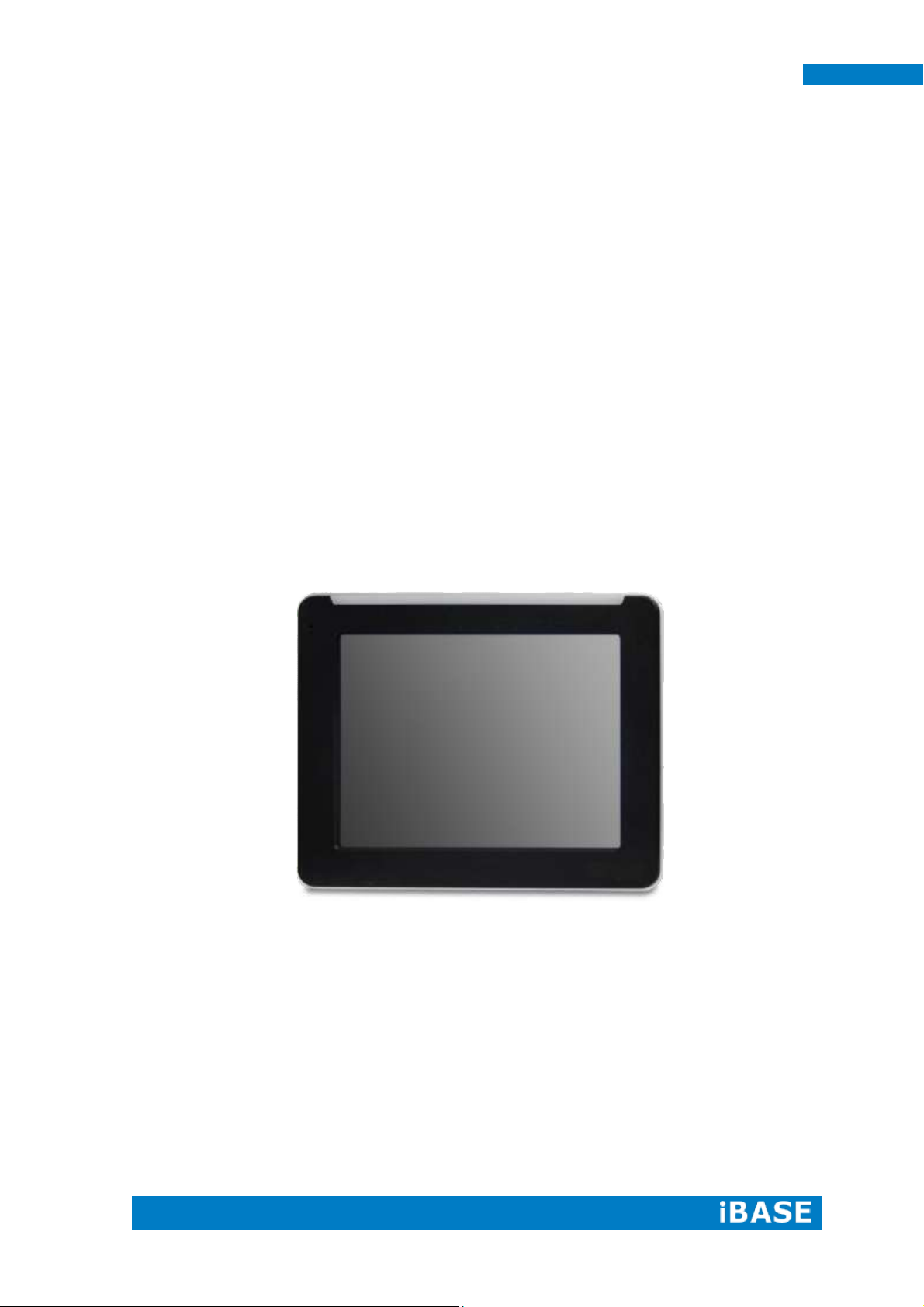
MRS-801-RE, an 8” RISC-based Power-over-Ethernet panel PC, utilizes the
Freescale I.MX6 Cortex A9 Processor providing high computing performance and low
power consumption.
It comes with 1GB DDR3 memory and one 4GB eMMC and one SD card slot for
data storage. It has one Gigabit Ethernet LAN PoE, an RS-232/485 port and USB
OTG that are well suited for industrial applications. The unit is equipped with 5-side
IP65 protection. It supports Linux 3.x and Android 4.x. The MRS-801-RE supports
12V DC single power input.
MRS-801-RE overview
Page 10
2
MRS-801-RE User Manual
Model Name
MRS-801-RE
System Mainboard
IB102
CPU
Freescale I.MX6 Cortex A9 Solo (1 Cores @ 1GHz)
Memory
1GB DDR3 memory
I/O Interface
1x USB (USB Host. A-Type)
1x USB OTG (mini USB B Type)
1x RS-232/485 via RJ45 connector
1x GbE LAN POE 802.3at
1x Power reset button Switch
1x 12V DC-in power jack
Storage
1x 4GB eMMC onboard
1x SD card slot
Expansion Slots
None
Power Supply
12V DC input/POE
LCD Size
8” TFT LCD
LCD Color
262K
LCD Resolution
800 x 600
LCD Brightness
250
LCD View Angle (H°/V°)
140/120
Backlight MTBF
30,000 hrs
Touch Screen
Resistive Touch Screen
Construction
Plastic
Mounting
VESA 75x75mm
Dimensions
(W)x(D)x(H) mm
211.6 x 171.2 x 33.5
Operating Temperature
0°C~ 50°C
Storage Temperature
-20°C ~ 60°C
Relative Humidity
10%~90% (non-condensing)
Protection Class
IP65 front bezel
Certification
CE/FCC Class A
Operating System
Support
Linux3.X,Android4.X
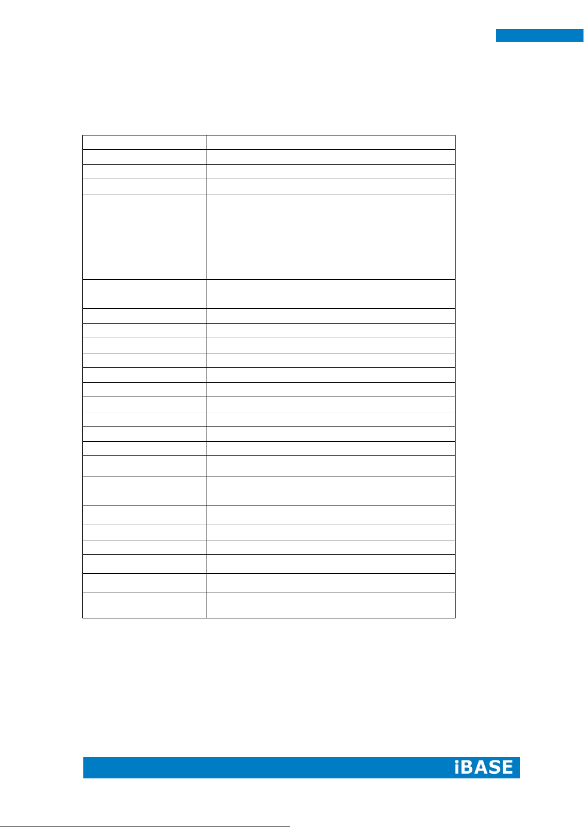
1.2 System Specification
1.2.1 Hardware Specifications
‧
This specification is subject to change without prior notice.
Page 11
Copyright © 2013 IBASE Technology Inc. All Rights Reserved.
3
IBASE Technology Inc.
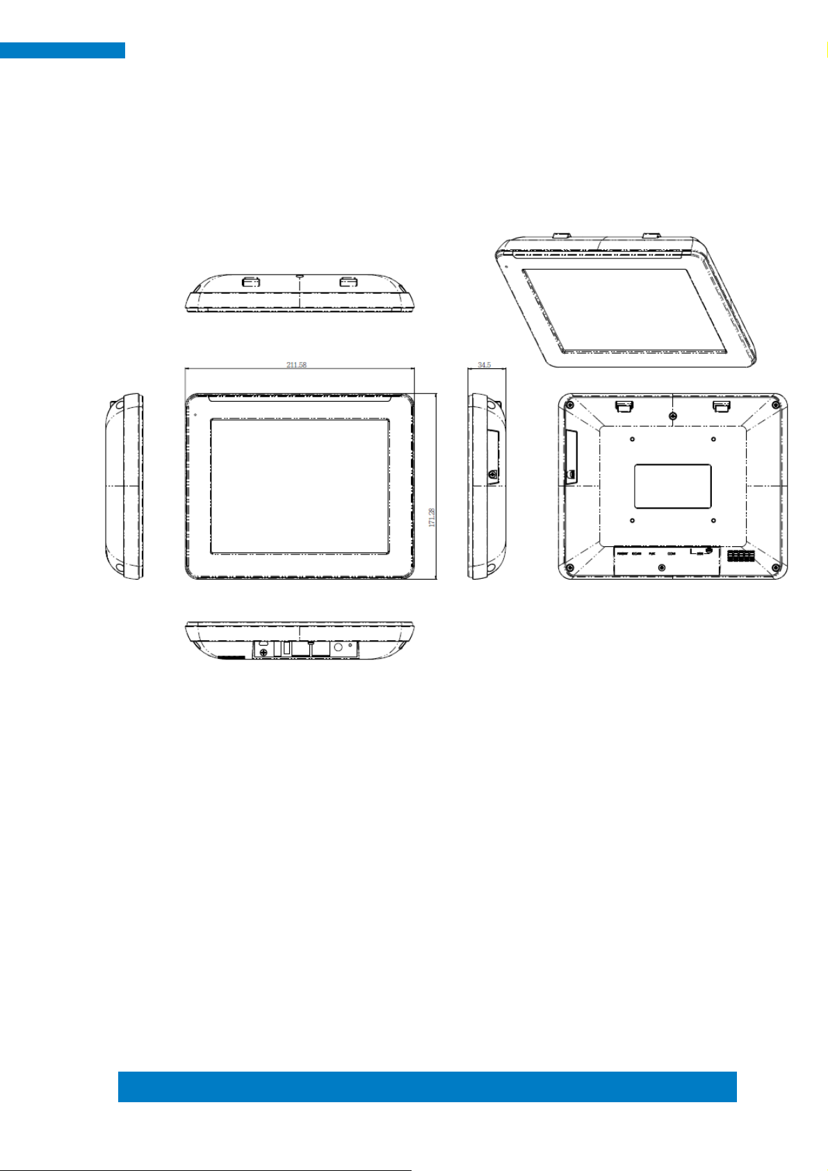
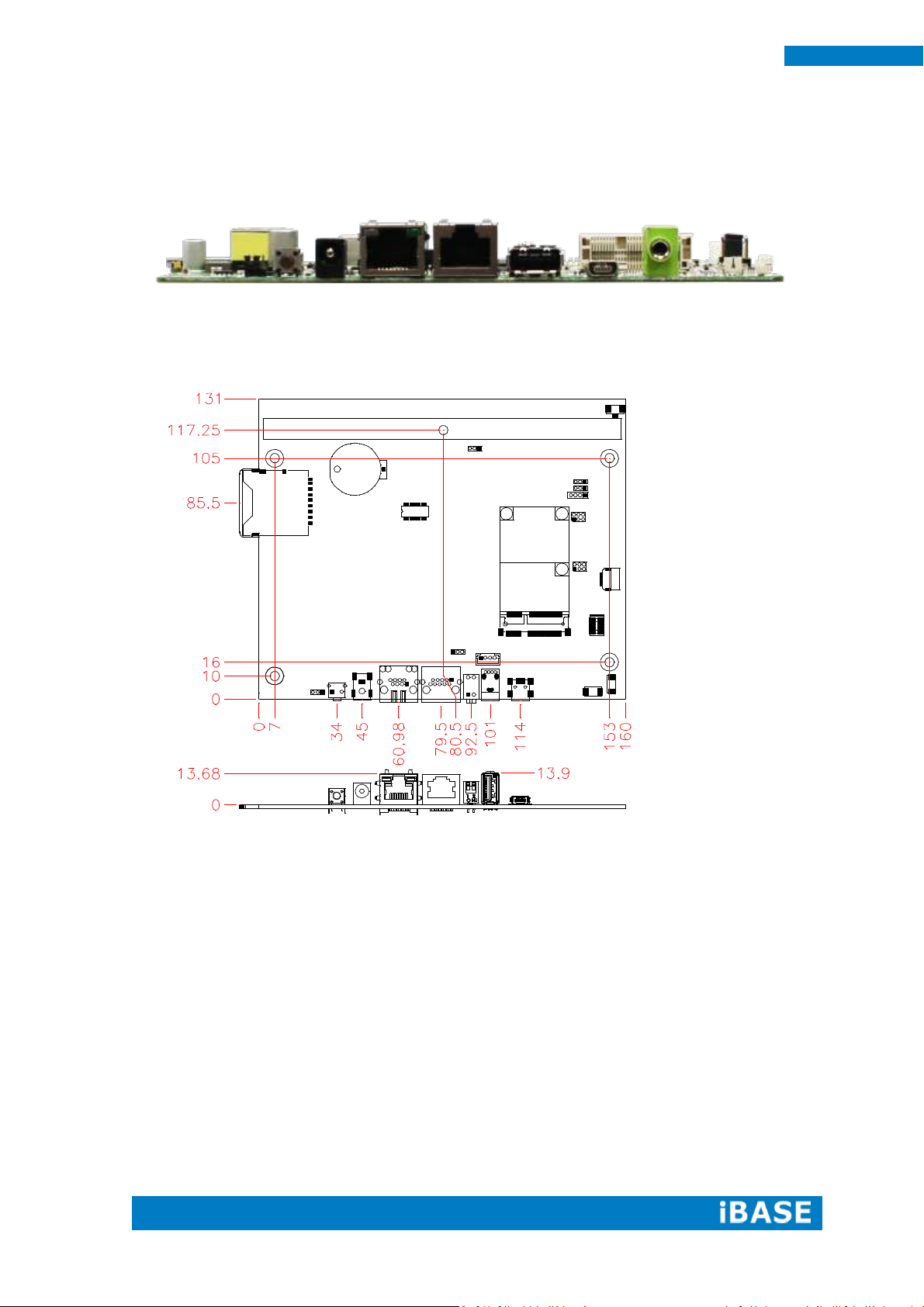
1.2.2 Dimensions
MRS-801-RE
Page 12
4
MRS-801-RE User Manual
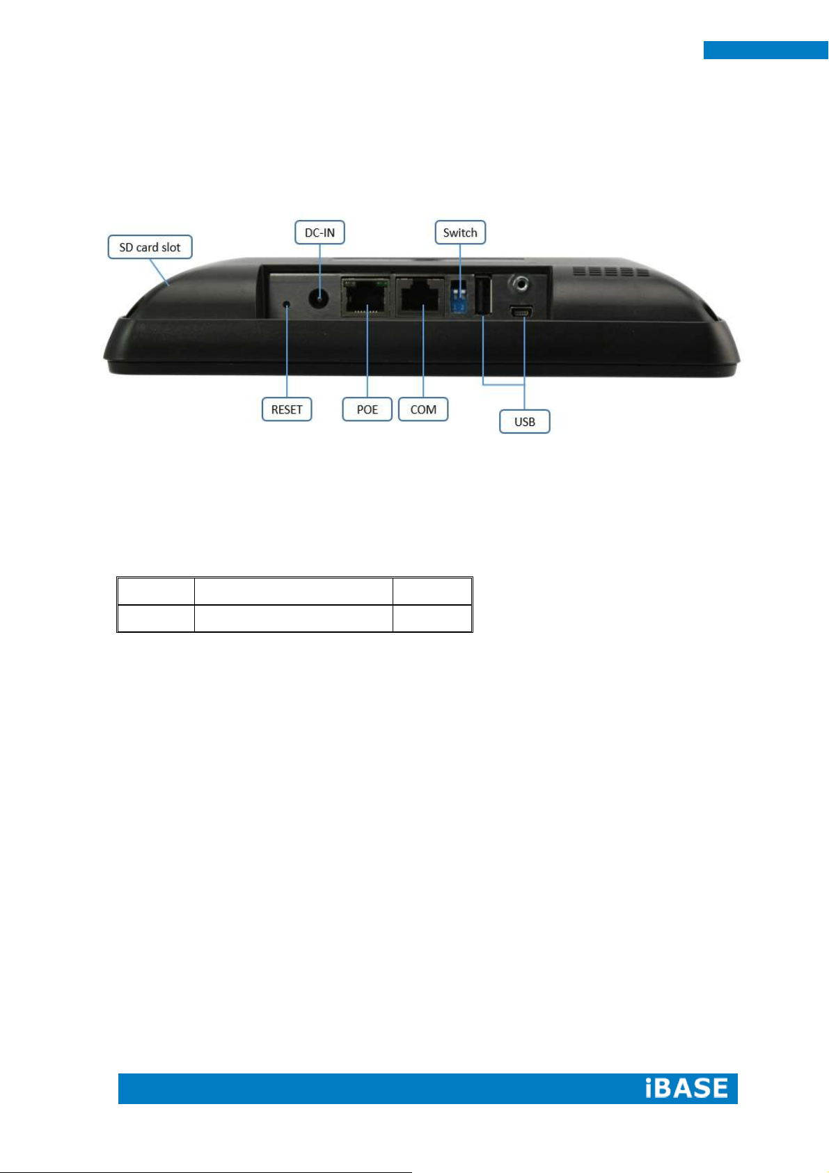
Part No.
Description
Quantity
1
60W power adaptor
1 pc
1.2.3 I/O View
1.3 Packing List
Page 13
Copyright © 2013 IBASE Technology Inc. All Rights Reserved.
5
IBASE Technology Inc.
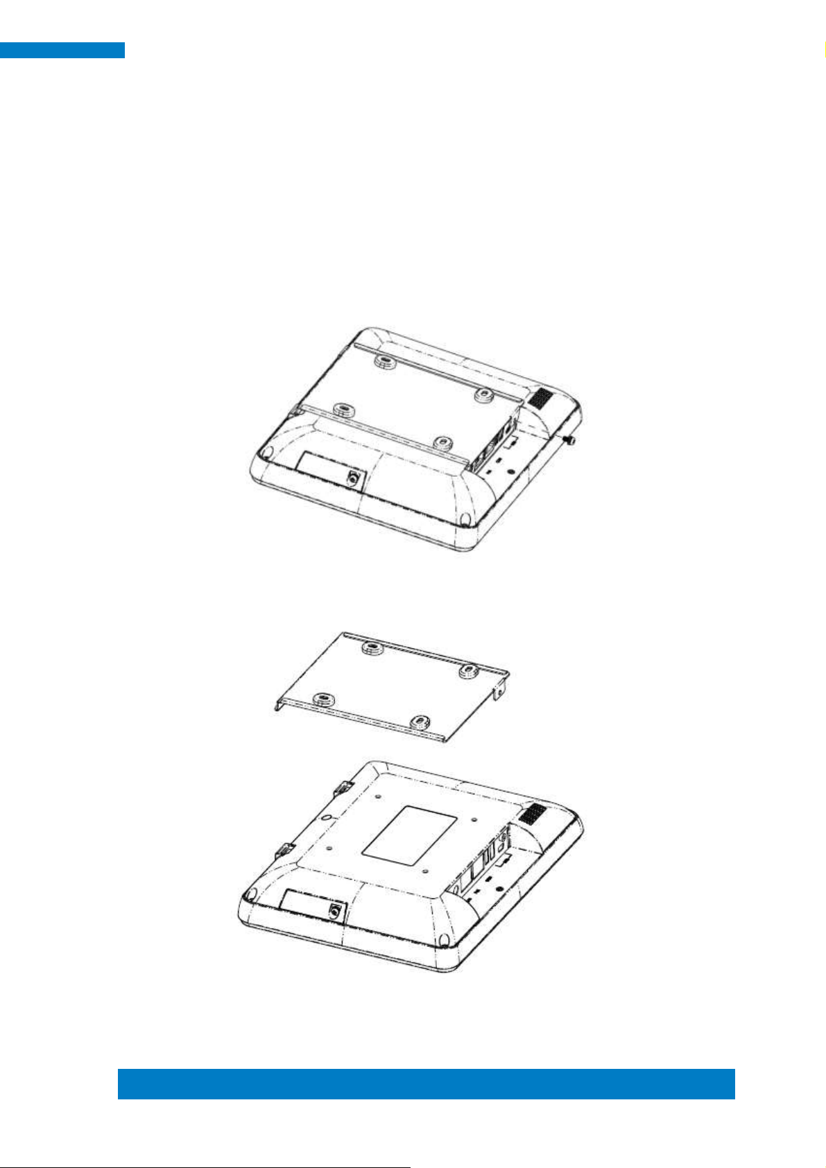
1.4 Installation
1.4.1 Installing wall mount
1. Loosen one screw and then replace the mounting bracket.
Page 14
6
MRS-801-RE User Manual
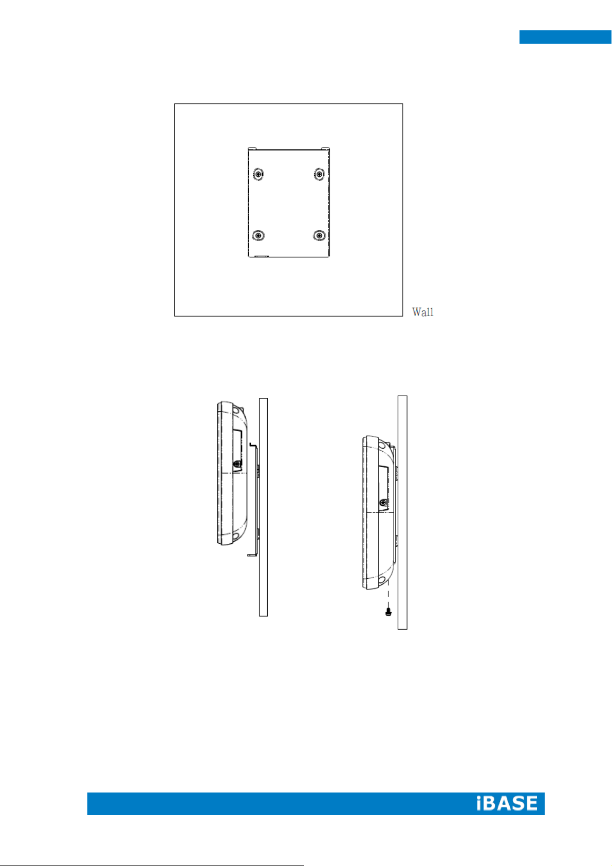
2. Install the mounting bracket on the wall.
3. Hang up the MRS-801-RE on the wall and twist one screw as shown.
Page 15
Copyright © 2013 IBASE Technology Inc. All Rights Reserved.
7
IBASE Technology Inc.
Specifications – Mainboard
Product Name
IB102
Form Factor
150mm x 165mm
CPU Type
Freescale i.MX6 Solo Core Coretex-A9 on Board
CPU Speed
1GHz
Memory
DDR3 1GB on Board
VGA Controller
IPU v3H IPU Engine
Edge IO
10/100/1000 LAN x1 (RJ45 connector with POE+ support )
USB x 1 (USB Host. A-Type)
USB OTG x 1 (mini AB type)
COM1 RS-232/422/485 x 1
Dip switch x 1 (for 232/485 selection)
SD card slot x 1
Reset button x1
12V DC-IN Jack x 1,
Internal Headers
LVDS Connector x 1
GPIO x (10pin, pitch 2.0 with 3.3V, refer to RP100)
Audio pin Header x3
I2C connector x1
Battery: BR2032 with socket
Expansion Slots
miniPCIE x1 ( with USB support)
Others
LEDs light bar x 1 (3xGPIO pin control Red, Orange and Green)
Operating
Temperature
0~60 degree
SW Support
1. Ubuntu Linux 11.10 ( kernel 3.0)
2. Android 4.3
CHAPTER 2 MOTHERBOARD INTRODUCTION
2.1 Introduction
The IB102 i.MX6 SBC comes with extended consumer-grade Freescale i.MX6
Solo Core Cortex-A9 1GHz CPU. LVDS, POE+, and light bar design to bring you the
scalability and flexibility you need. The device offers 3D graphics acceleration, while
also supporting numerous peripherals, including DDR3, RS232/422/485 port and
USB OTG that are well suited for industrial applications.
This specification is subject to change without prior notice.
Page 16
8
MRS-801-RE User Manual
I/O View
Board Dimensions
Page 17
Copyright © 2013 IBASE Technology Inc. All Rights Reserved.
9
IBASE Technology Inc.
2.2 Setting Jumpers
[Important] Please check the jumpers, DIP, buttons and switches on IB102
before doing the panel connection and boot up.
Jumpers are used on IB102 to select various settings and features according to
your needs and applications. Contact your supplier if you have doubts about the best
configuration for your needs. The following lists the connectors on IB102 and their
respective functions.
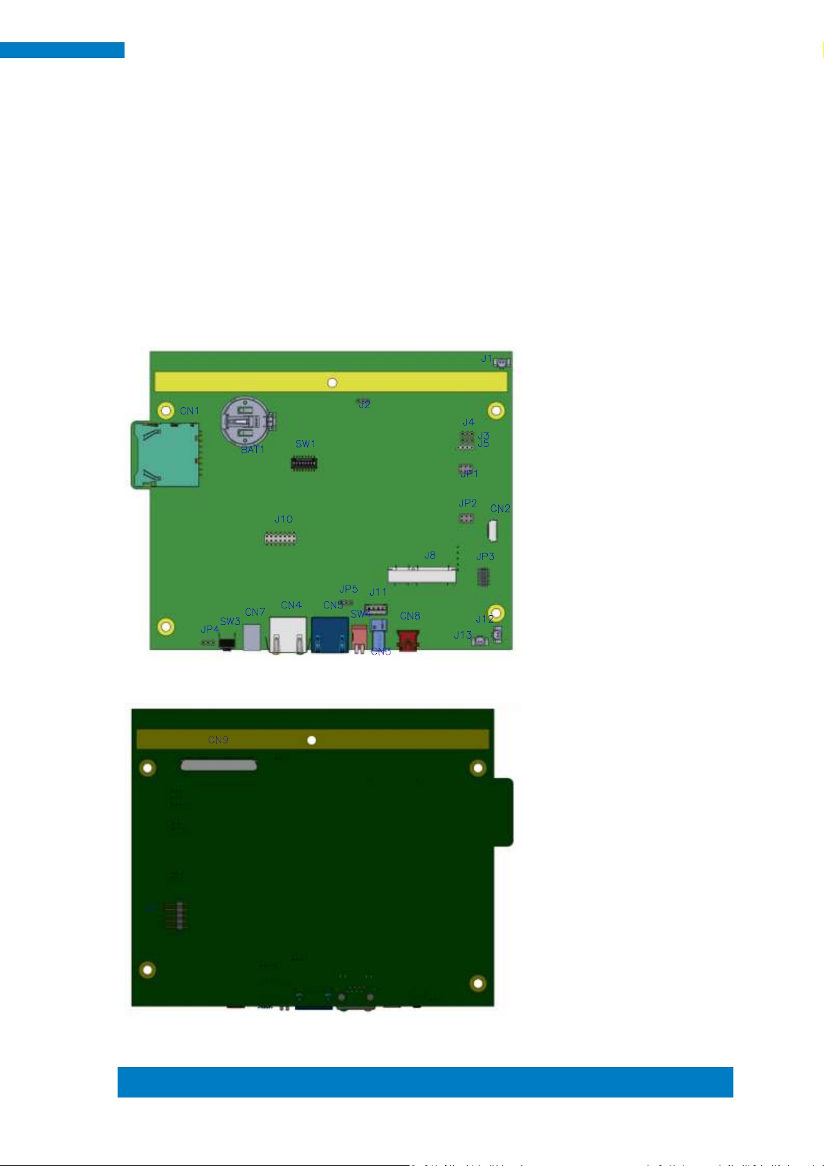
Jumper Locations on IB102
Top Side
Bottom Side
Page 18
10
MRS-801-RE User Manual
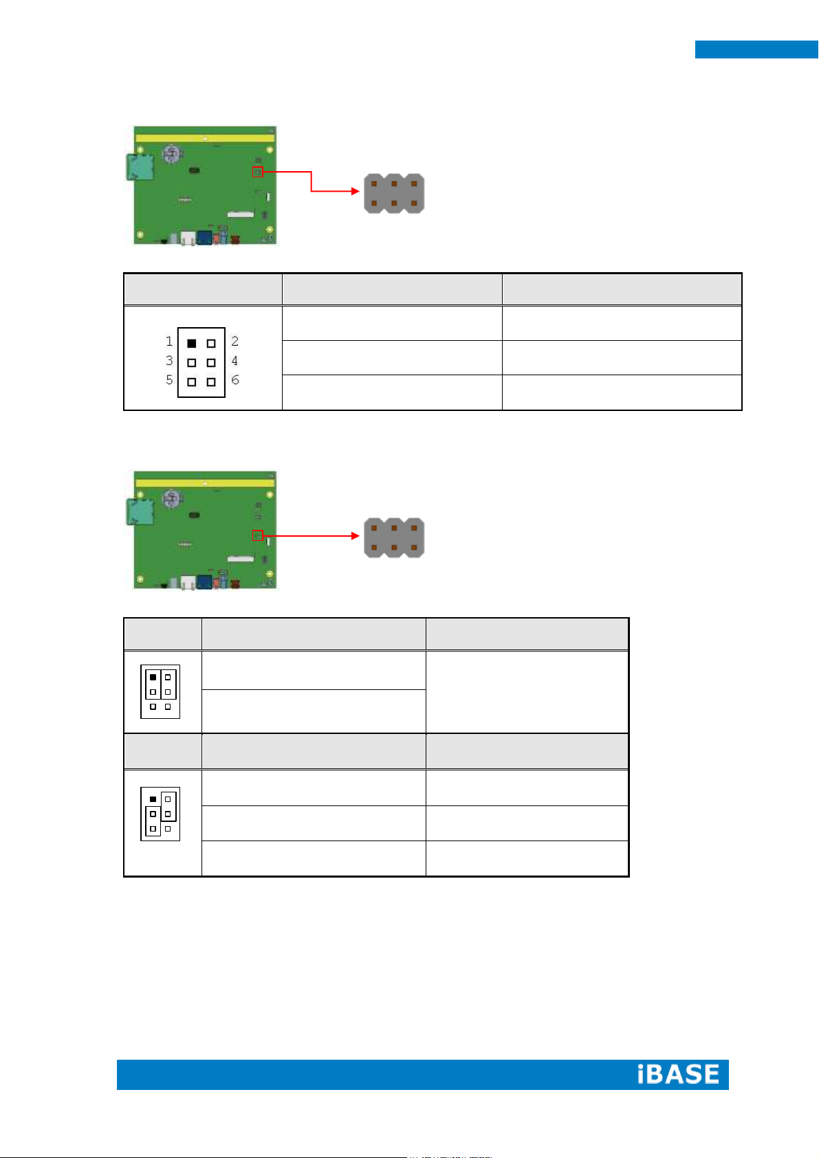
JP1
Setting
Function
Pin 1-2 Short/Open
4 or 8 wire/5 wire (Default)
Pin 3-4 Short/Open
4 or 8 wire/5 wire (Default)
Pin 5-6 Short/Open
4 or 8 wire/5 wire (Default)
JP2
USB Setting*
Function
1
3
2
4
5 6
Pin 1-3 Short/Closed
USB
Pin 2-4 Short/Closed
JP2
UART Setting
Function
1
3
2
4
5 6
Pin 3-5 Short/Closed
UART*
Pin 2-4 Short/Closed
Baud rate 19200*
Pin 4-6 Short/Closed
Baud rate 9600
1 6 5
2
1 6 5
2
JP1: Touch Pad Wire Setting 2.0mm
JP2: Touch USB/UART Mode Setting 2.0mm
Page 19
Copyright © 2013 IBASE Technology Inc. All Rights Reserved.
11
IBASE Technology Inc.
JP4
Setting
Function
Pin 1-2 Short/Closed
GPIO
Pin 2-3 Short/Closed
System Reset (Default)
11 2 12
1
1
3
JP3: Program Interface (E-CALL 0519-03-2161-120) (Factory
use only)
JP4: System reset/GPIO Mode Setting 2.0mm
Page 20
12
MRS-801-RE User Manual
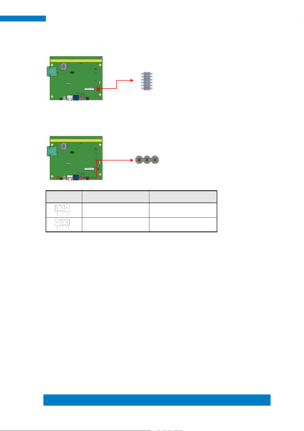
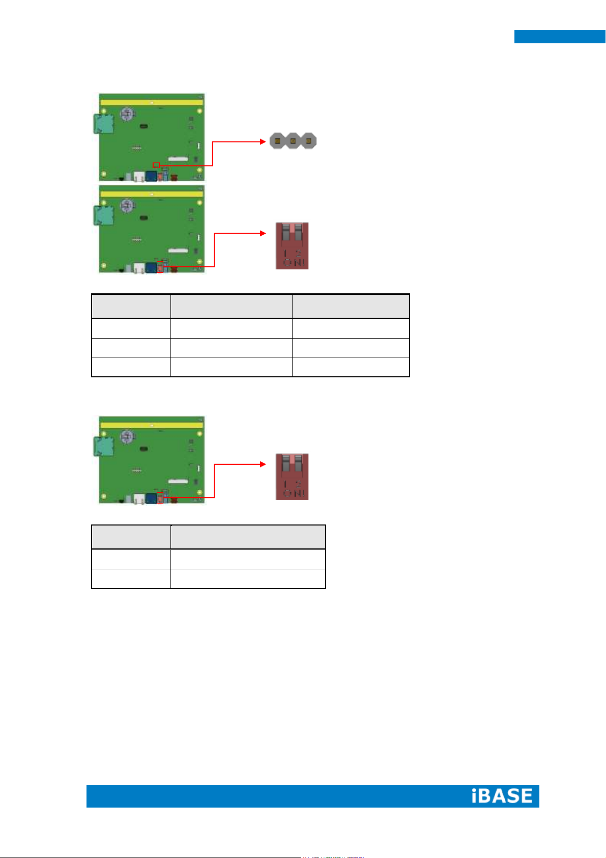
COM1 Mode
SW4 (S2)
JP5
RS-232
Off (Default)
2-3 Short (Default)
RS-485
On
2-3 Short
RS-422
Off
1-2 Short
SW4 (S1)
Device Mode
On
None Terminal (Default)
Off
Terminal
s2
s1 1 3
S2
S1
JP5, SW4 (S2): RS-232/422/485 Mode Selection 2.0mm
SW4 (S1): RS-422/485 Device Termination Selection
Page 21
Copyright © 2013 IBASE Technology Inc. All Rights Reserved.
13
IBASE Technology Inc.
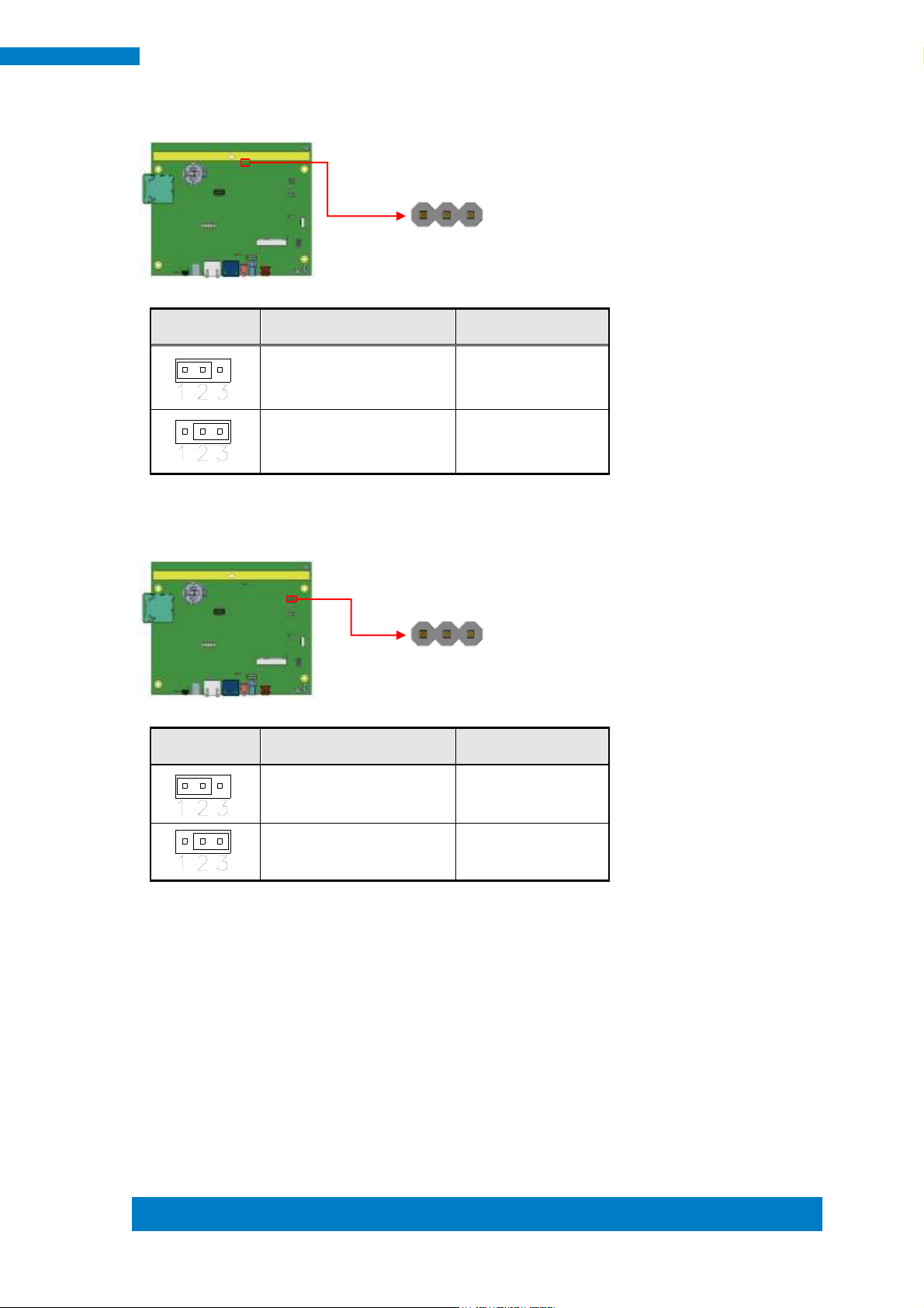
J2
Setting
Panel Voltage
Pin 1-2 Short/Closed
5V (default)
Pin 2-3 Short/Closed
12V
J3
Setting
Panel Voltage
Pin 1-2 Short/Closed
5V
Pin 2-3 Short/Closed
3.3V (default)
1
3
1
3
J2: BL Voltage Setting 2.0mm
J3: BL ADJ Level Setting 2.0mm
Page 22
14
MRS-801-RE User Manual
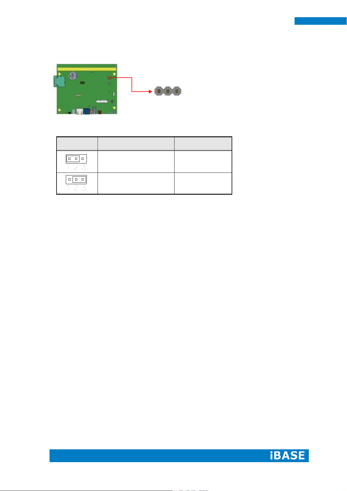
J4
Setting
Panel Voltage
Pin 1-2 Short/Closed
5V
Pin 2-3 Short/Closed
3.3V (default)
1
3
J4: LVDS Panel Power Selection 2.0mm
Page 23
Copyright © 2013 IBASE Technology Inc. All Rights Reserved.
15
IBASE Technology Inc.
Pin #
Signal Name
1
GND
2
NC
3
NC
4
NC
5
NC
6
GND
7
SDA
8
SCL
9
NC
10
INT
11
3.3V
12
3.3V
1
1
2
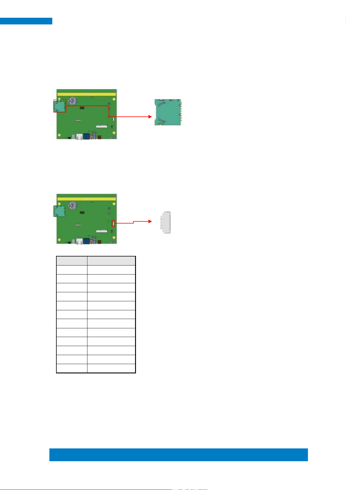
2.3 Connectors on IB102
CN1: SD Card Connector
CN2: Capacitor Touch Pad Connector (ENTERY
7083K-F12N-04L)
Page 24
16
MRS-801-RE User Manual
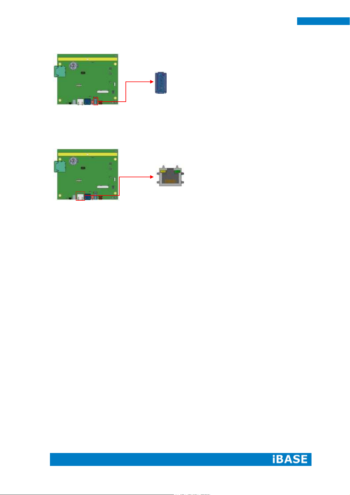
CN3: USB 2.0 Connector
CN4: 10/100/1000Mb LAN (PoE+ supported)
This RJ45 LAN connector supports PoE+ function.
Page 25
Copyright © 2013 IBASE Technology Inc. All Rights Reserved.
17
IBASE Technology Inc.
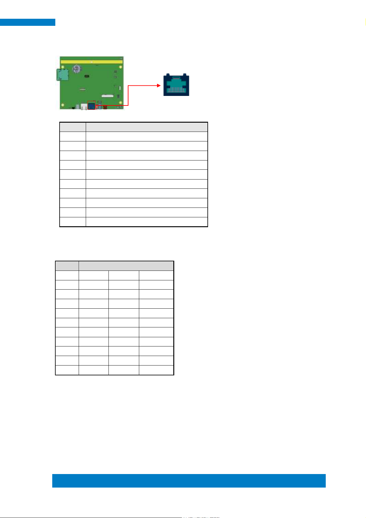
Pin #
Signal Name
1
COM1 DSR, Data set ready
2
GND
3
GND
4
COM1 RXD, Receive data
5
COM1 TXD, Transmit data
6
COM1 DCD, Data carrier detect
7
COM1 DTR, Data terminal ready
8
COM1 CTS, Clear to send
9
COM1 RTS, Request to send
10
Boot by SD card detection
Pin #
Signal Name
RS-232
R2-422
RS-485
1
DSR
NC
NC
2
Ground
Ground
Ground
3
Ground
Ground
Ground
4
RX
TX+
DATA+
5
TX
RX+
NC
6
DCD
TX-
DATA-
7
DTR
RX-
NC
8
CTS
NC
NC
9
RTS
NC
NC
10
NC
NC
NC
10
1
CN5: COM1 RJ45 Connector
COM1 is jumper less for RS-232, RS-422 and RS-485 and configured
with SW4 (S2) and JP5 Selection.
[
Page 26
18
MRS-801-RE User Manual
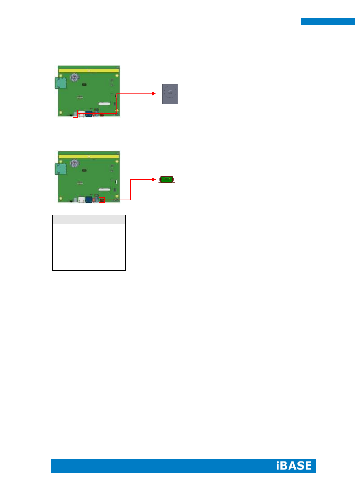
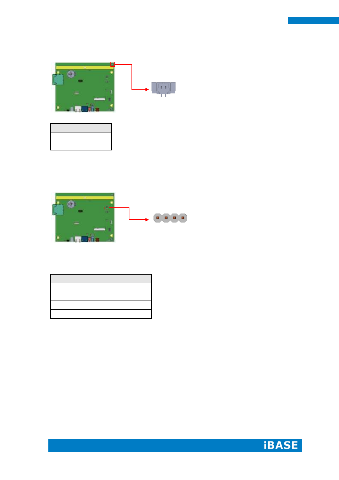
Pin #
Signal Name
1
+5V
2
D-
3
D+
4
ID
5
GND
1
5
CN7: +12V DC-IN Power Connector
CN8: Mini USB OTG Connector
Note: CN8 will be used for USB device when ID is floating.
Page 27
Copyright © 2013 IBASE Technology Inc. All Rights Reserved.
19
IBASE Technology Inc.
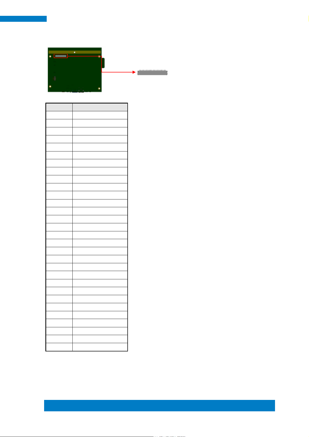
Pin #
Signal Name
1
NC
2
LCD_VDD
3
LCD_VDD
4
NC
5
TX0-
6
TX0+
7
GND
8
TX1-
9
TX1+
10
GND
11
TX2-
12
TX2+
13
GND
14
CLK-
15
CLK+
16
GND
17
TX3-
18
TX3+
19
GND
20
GND
21
GND
22
GND
23
GND
24
NC
25
BKLT_ADJ
26
BKLT_EN
27
NC
28
BKLT_VCC
29
BKLT_VCC
30
BKLT_VCC
1
30
CN9: LVDS Connector (HRS DF19G-30P-1H(54) )
Page 28
20
MRS-801-RE User Manual
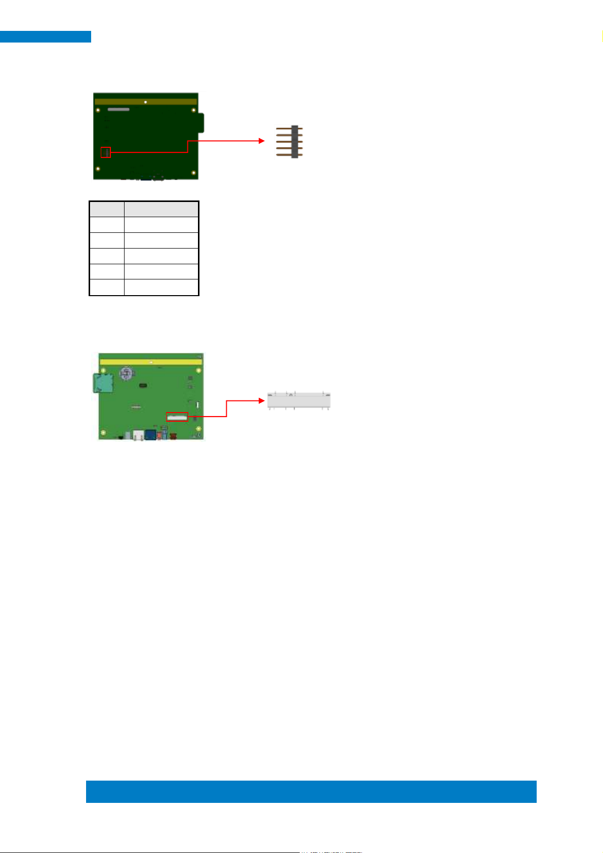
Pin #
Signal Name
1
MIC Input
2
GND
Pin #
Signal Name
1
COM2 RXD, Receive Data
2
COM2 TXD, Transmit Data
3
GND
4
NC
2
1
1
4
J1: Mic Connector (WT04M-30003-02032)
J5: COM2 RS232 Connector, Debug Port Connector 2.0mm
(Factory use only)
Page 29
Copyright © 2013 IBASE Technology Inc. All Rights Reserved.
21
IBASE Technology Inc.
Pin #
Signal Name
1
Touch XP
2
Touch XM
3
Touch SG
4
Touch YP
5
Touch YM
1
5
J7: Resistive Touch Panel Connector 2.5mm
J8: Mini PCI-E Connector
Page 30

22
MRS-801-RE User Manual
Signal Name
Pin #
Pin #
Signal Name
3.3V
1 2 GPIO2
GPIO1
3 4 GPIO5
GPIO3
5 6 GPIO8
GPIO7
7 8 Reset
GPIO9
9
10
Watch Dog
GPIO10
11
12
GPIO11
GPIO12
13
14
GND
Pin #
Signal Name
1
+5V
2
D-
3
D+
4
GND
14
1
2
13
4
1
J10: Digital In/Out Connector 2.0mm
J11: USB2.0 Connector (JST B4B-PH-K-S)
Page 31

Copyright © 2013 IBASE Technology Inc. All Rights Reserved.
23
IBASE Technology Inc.
Pin #
Signal Name
1
SPEAKER_RIGHT+
2
SPEAKER_RIGHT-
Pin #
Signal Name
1
SPEAKER_LEFT-
2
SPEAKER_LEFT+
1
2 2 1
J12: Speaker Right-Out Connector (WT04M-30003-02032)
J13: Speaker Left-Out Connector (WT04M-30003-02032)
SW3: System Reset Button
Page 32

24
MRS-801-RE User Manual
CHAPTER 3 Software SETUP
Basically, the IB102 is preloaded O.S (Android / Linux) into eMMC by default. Connect
the 8” LVDS panel (optional) with IB102, and 12V/ POE+ power directly.
3.1 Make a Recovery SD Card (for advanced user only)
For advanced user who has Ibase standard image file, refer to this
chapter to prepare the recovery boot-up SD card. Ibase optionally
provides 8” LVDS panel for users to prepare the software application
pre-development easily under Linux / Android platform.
Preparing the Recovery SD card to install the Linux/ Android image
into eMMC
Note: all data in the eMMC will be erased.
-- for IB102
Please download the Recovery SD card’s image by FTP in advance.
Host: 219.87.145.180 port: 21
User: bsp
Password: (please check with your sales)
Image path: (image path may change / update)
/bsp/RISC_IMAGE/IB102/IB102/Linux/IB102-Linux_3.0.35-v1.1.rar
/bsp/RISC_IMAGE/IB102/IB102/Android/IB102-Android_4.3-v1.1.rar
(based on Freescale BSP: L3.3.35.4.1.0)
Page 33

Copyright © 2013 IBASE Technology Inc. All Rights Reserved.
25
IBASE Technology Inc.
For advanced users who want to return to the factory reset status, the
instructions below will guide you through installing a recovery program on your
SD card to allow you to easily install the default OS’s and to recover your card
when needed.
1. Insert an SD card that is 8GB or greater in size into your computer
2. Format the SD card
i. Download the SD Association's Formatting Tool (SD Card Formatter 4.0 )
from
https://www.sdcard.org/downloads/formatter_4/eula_windows/
ii. Install and run the Formatting Tool on your machine
iii. Set "FORMAT SIZE ADJUSTMENT" option to "ON" in the "Options"
menu
iv. Check that the SD card you inserted matches the one selected by
the Tool
v. Click the “Format” button
3. Download the target operating system image from the DVD/ or FTP
(Descripted in previous page)
4. Download the Win32DiskImager from
http://sourceforge.net/projects/win32diskimager/ and use it to restore
the target operating system.
And then, flash the Android/ Linux image into your SD card in your PC (Windows).
6. Please check insert (special COM1 RJ45 dongle, pin3 short to pin10, this
dongle is for IB102 only) and make sure it can boot from SD Card by
checking item8.
Page 34

26
MRS-801-RE User Manual
--- Boot Up with IB102---
Please double check the Boot device selection before powering on.
IB102, by default, is set to boot up from eMMC.
1. Insert the SD card/MicroSD into the motherboard. Make sure the 8”
panel (or your own panel) is connected and connect the power supply to
boot up the system.
2. Recovery program on your SD card will execute automatically. The eMMC
on PCB will be formatted and the OS will be installed while the progress
bar shows 100% complete.
3. Remove the power and the recovery SD. Remember to remove the
special RJ45 dongle.
4. Connect the power and boot up the IB102,; you will see the Linux/
Android boot up pages.
Note for IB102A:
IB102A, by default, is set to boot up from SD card only. Just insert/
prepare your SD card, and connect the power. To create IB102A SD card
images, please download the boot SD card’s image by FTP in
advance.
/bsp/RISC_IMAGE/IB102/IB102A/Linux_sd/ IB102A_Linux_3.0.35_1.1.rar
/bsp/RISC_IMAGE/IB102/IB102A/Android_sd/IB102A_Andoird_4.3_1.1.rar
Page 35

Copyright © 2013 IBASE Technology Inc. All Rights Reserved.
27
IBASE Technology Inc.
Pin #
Signal Name
1
COM2 RXD, Receive Data
2
COM2 TXD, Transmit Data
3
GND
4
NC
1
4
3.2 Parameter Setting on U-boot
IB102 supports 8” LVDS panel (optional) by default. If you have any
other LVDS panel to be customized, please contact Ibase sales or FAE
staff.
3.2.1 Preparation (debug console)
i. The COM1 (Tx1, Rx1) is the default debug port. Check that it can be
connected to (RX, Tx) in your PC environment.
ii. Use 115200 bps (8n1, no flow control) in Windows terminal (for
example Putty.exe)
iii. During system boot up, you can press “Enter” to stop auto boot and
modify your environment.
(Note: For users who are not sure about the COM connection, please
check if Board.COM1.Tx1 is connected to PC.COM.Rx ;
Board.COM1.Rx1 to PC.COM.Tx)
J5: COM2 RS232 Connector, Debug Port Connector
(Factory use only)
Page 36

28
MRS-801-RE User Manual
MX6SDL SABREDS U-BOOT > setenv bootcmd “booti mmcX”
setenv bootargs 'console=ttymxc0,115200 androidboot.console=ttymxc1
androidboot.hardware=freescale init=/init vmalloc=400M
video=mxcfb0:dev=ldb,IB102-XGA,if=RGB666 ldb=sep0'
MX6SDL SABREDS U-BOOT > saveenv
MX6SDL SABREDS U-BOOT > boot
3.2.2 Display setting command For Android (for advanced software
engineers only)
With the debug port, follow the reference command examples to help
you to be familiar with display modification.
Select boot device:
Where mmcX =1, means boot from SD card.
Where mmcX =2, means boot from eMMC device.
Command to set 8” LVDS panel (default):
(Please also save the environment and reboot with the following
command.)
Page 37

Copyright © 2013 IBASE Technology Inc. All Rights Reserved.
29
IBASE Technology Inc.
setenv bootargs_base 'setenv bootargs mem=1G console=ttymxc1,115200'
setenv bootcmd_mmc 'run bootargs_base bootargs_mmc; mmc dev 2; mmc read
${loadaddr} 0x800 0x2000; bootm'
setenv bootargs_mmc 'setenv bootargs ${bootargs} root=/dev/mmcblk0p1 rootwait rw
video=mxcfb0:dev=ldb,IB102-XGA,if=RGB666 ldb=sep0 video=mxcfb1:off
video=mxcfb2:off fbmem=15M rootfstype=ext4'
Carrier SD : root=/dev/mmcblk1p1
MX6SDL SABREDS U-BOOT > saveenv
MX6SDL SABREDS U-BOOT > boot
3.2.3 Display setting for Linux
Command to set 8” panel (Default):
Command to set the boot device
Note: (remember to save the environment and reboot with the following
command)
Page 38

30
MRS-801-RE User Manual
CHAPTER 4 BSP User Guide ( for advanced software engineer
only )
This Chapter is an example only, and it is mainly for advanced
SW engineers to build the image for IBASE ARM PCB. Any
other modification, new device or driver should be handled
carefully.
4.1 Building BSP Source
4.1.1 Preparation
Suggested Host Platform: Ubuntu 10.04 x64 version
Install necessary packages before build:
apt-get install build-essential uboot-mkimage ia32-libs
Note: ** To simplify build process, please run build/installation with root
on your x86 host PC. **
4.1.2 Installing Toolchain
Download and extract freescale toolchain
(gcc-4.6.2-glibc-2.13-linaro-multilib-2011.12.tgz)
# assume your toolchain file is located at root home dir:
sudo su
cd ~
Page 39

Copyright © 2013 IBASE Technology Inc. All Rights Reserved.
31
IBASE Technology Inc.
mkdir -p /opt/freescale/usr/local/
cd /opt/freescale/usr/local/
tar xvf ~/gcc-4.6.2-glibc-2.13-linaro-multilib-2011.12.tgz
Page 40

32
MRS-801-RE User Manual
Page 41

Copyright © 2013 IBASE Technology Inc. All Rights Reserved.
33
IBASE Technology Inc.
4.1.3 Building u-boot
# Assume your linux BSP u-boot source is
at~/linux_bsp/u-boot_2009_08/DL/u-boot
cd ~/linux_bsp/u-boot_2009_08/DL/u-boot
make ARCH=arm
CROSS_COMPILE=/opt/freescale/usr/local/gcc-4.6.2-glibc-2.13-linaro-multilib-2011.12/fsl-lin
aro-toolchain/bin/arm-none-linux-gnueabi- distclean
Page 42

34
MRS-801-RE User Manual
make ARCH=arm
CROSS_COMPILE=/opt/freescale/usr/local/gcc-4.6.2-glibc-2.13-linaro-multilib-2011.12/fsl-lin
aro-toolchain/bin/arm-none-linux-gnueabi- mx6solo_sabresd_config
Page 43

Copyright © 2013 IBASE Technology Inc. All Rights Reserved.
35
IBASE Technology Inc.
Page 44

36
MRS-801-RE User Manual
make ARCH=arm
CROSS_COMPILE=/opt/freescale/usr/local/gcc-4.6.2-glibc-2.13-linaro-multilib-2011.12/fsl-lin
aro-toolchain/bin/arm-none-linux-gnueabi-
Note: **** If the building process is successful, u-boot.bin file will be generated. ****
Page 45

Copyright © 2013 IBASE Technology Inc. All Rights Reserved.
37
IBASE Technology Inc.
Page 46

38
MRS-801-RE User Manual
4.1.4 Building kernel
# Assume your linux kernel source is at ~/linux_bsp/kernel-3.0.35
cd ~/linux_bsp/kernel-3.0.35
make ARCH=arm clean
make ARCH=arm
CROSS_COMPILE=/opt/freescale/usr/local/gcc-4.6.2-glibc-2.13-linaro-multilib-
2011.12/fsl-linaro-toolchain/bin/arm-none-linux-gnueabi- uImage
Page 47

Copyright © 2013 IBASE Technology Inc. All Rights Reserved.
39
IBASE Technology Inc.
**** If the building process is successful, uImage file will be generated
under arch/arm/boot directory. ****
Page 48

40
MRS-801-RE User Manual
Page 49

Copyright © 2013 IBASE Technology Inc. All Rights Reserved.
41
IBASE Technology Inc.
4.1.5 Copying u-boot, kernel to SD card
Insert an empty SD card with at least 8GB size and put it in a card reader
connecting to your host PC. Assume your SD card is /dev/sdb on your
x86 host PC
# Copying the u-boot Boot Loader Image
sudo dd if=u-boot.bin of=/dev/sdb bs=512 seek=2 skip=2 conv=fsync
# Copying the Kernel Image
sudo dd if=uImage of=/dev/sdb bs=512 seek=2048 conv=fsync
4.1.6 Copying Filesystem to SD card
Assume your SD card is /dev/sdb.
# Copying the Root File System (rootfs)
First, a partition table must be created. If a partition already exists and it
is big enough for the file system you want to deploy, then you can skip
this step.
Page 50

42
MRS-801-RE User Manual
To create a partition, at offset 16384 (in sectors of 512 bytes) enter the
following
command:
sudo fdisk /dev/sdb
NOTE
On most Linux host operating systems, SD card will be mounted
automatically upon insertion. Therefore, before running fdisk, please
make sure that SD card is unmounted (via 'sudo umount /dev/sdb').
Type the following parameters (each followed by <ENTER>):
u [switch the unit to sectors instead of cylinders]
d [repeat this until no partition is reported by the 'p' command ]
n [create a new partition]
p [create a primary partition]
1 [the first partition]
16384 [starting at offset sector #16384, i.e. 8MB, which leaves enough space for
the kernel, the boot loader and its configuration data]
<enter> [using the default value will create a partition that spans to the last sector
of the medium]
w [ this writes the partition table to the medium and fdisk exits]
The file system format ext3 or ext4 is a good option for removable media due to the
built-in journaling. Run the following command to format the partition:
Page 51

Copyright © 2013 IBASE Technology Inc. All Rights Reserved.
43
IBASE Technology Inc.
sudo umount /dev/sdb1
Page 52

44
MRS-801-RE User Manual
sudo mkfs.ext4 /dev/sdb1
Page 53

Copyright © 2013 IBASE Technology Inc. All Rights Reserved.
45
IBASE Technology Inc.
Copy the target file system to SD card partition by extracting rootfs
package to mounted directory:
(assume compressed root file system is F600_linux_fs.tgz)
mkdir /tmp/SD
sudo mount /dev/sdb1 /tmp/SD
cd /tmp/SD
Page 54

46
MRS-801-RE User Manual
tar xvf ~/linux_bsp/F600_linux_fs.tgz
Page 55

Copyright © 2013 IBASE Technology Inc. All Rights Reserved.
47
IBASE Technology Inc.
Copying the file system takes several minutes. The file system content is now on the
media.
Page 56

48
MRS-801-RE User Manual
4.1.7 Booting with your SD card
(For advance software users only)
Put SD card in your board and insert special COM port dongle to boot from SD.
Connect a debug cable to debug port with serial port 115200/N/8/1 setting on your
PC’s serial port program such hyperterminal/teraterm. Connect LVDS panel. Power
on and you will see u-boot prompt.
At u-boot prompt, press Enter before time out. Type the following setting to boot from
SD card + LVDS panel:
setenv bootcmd_mmc 'run bootargs_base bootargs_mmc; mmc dev 1; mmc read
${loadaddr} 0x800 0x2000; bootm'
setenv bootargs_mmc 'setenv bootargs ${bootargs} root=/dev/mmcblk1p1 rootwait rw
video=mxcfb0:dev=ldb,IB102-XGA,if=RGB666 ldb=sep0 video=mxcfb1:off video=mxcfb2:off
fbmem=15M rootfstype=ext4'
saveenv
After that, prepare your LCD, power off and power on again.
You can see Ubuntu Linux is running on monitor.
Page 57

Copyright © 2013 IBASE Technology Inc. All Rights Reserved.
49
IBASE Technology Inc.
Reading / writing i2c
i2cget.c
/*
i2cget.c - A user-space program to read an I2C register.
Copyright (C) 2005-2012 Jean Delvare <jdelvare@suse.de>
Based on i2cset.c:
Copyright (C) 2001-2003 Frodo Looijaard <frodol@dds.nl>, and
Mark D. Studebaker <mdsxyz123@yahoo.com>
Copyright (C) 2004-2005 Jean Delvare
This program is free software; you can redistribute it and/or modify
it under the terms of the GNU General Public License as published by
the Free Software Foundation; either version 2 of the License, or
(at your option) any later version.
This program is distributed in the hope that it will be useful,
but WITHOUT ANY WARRANTY; without even the implied warranty of
MERCHANTABILITY or FITNESS FOR A PARTICULAR PURPOSE. See the
GNU General Public License for more details.
You should have received a copy of the GNU General Public License
along with this program; if not, write to the Free Software
Foundation, Inc., 51 Franklin Street, Fifth Floor, Boston,
MA 02110-1301 USA.
*/
#include <sys/ioctl.h>
#include <errno.h>
#include <string.h>
#include <stdio.h>
#include <stdlib.h>
Appendix A– I2C, GPIO, Watchdog Reference Code Coding
How to use I2C in Linux
Page 58

50
MRS-801-RE User Manual
#include <unistd.h>
#include <linux/i2c-dev.h>
#include "i2cbusses.h"
#include "util.h"
#include "../version.h"
static void help(void) __attribute__ ((noreturn));
static void help(void)
{
fprintf(stderr,
"Usage: i2cget [-f] [-y] I2CBUS CHIP-ADDRESS [DATA-ADDRESS [MODE]]\n"
" I2CBUS is an integer or an I2C bus name\n"
" ADDRESS is an integer (0x03 - 0x77)\n"
" MODE is one of:\n"
" b (read byte data, default)\n"
" w (read word data)\n"
" c (write byte/read byte)\n"
" Append p for SMBus PEC\n");
exit(1);
}
static int check_funcs(int file, int size, int daddress, int pec)
{
unsigned long funcs;
/* check adapter functionality */
if (ioctl(file, I2C_FUNCS, &funcs) < 0) {
fprintf(stderr, "Error: Could not get the adapter "
"functionality matrix: %s\n", strerror(errno));
return -1;
}
switch (size) {
case I2C_SMBUS_BYTE:
if (!(funcs & I2C_FUNC_SMBUS_READ_BYTE)) {
fprintf(stderr, MISSING_FUNC_FMT, "SMBus receive byte");
return -1;
Page 59

Copyright © 2013 IBASE Technology Inc. All Rights Reserved.
51
IBASE Technology Inc.
}
if (daddress >= 0
&& !(funcs & I2C_FUNC_SMBUS_WRITE_BYTE)) {
fprintf(stderr, MISSING_FUNC_FMT, "SMBus send byte");
return -1;
}
break;
case I2C_SMBUS_BYTE_DATA:
if (!(funcs & I2C_FUNC_SMBUS_READ_BYTE_DATA)) {
fprintf(stderr, MISSING_FUNC_FMT, "SMBus read byte");
return -1;
}
break;
case I2C_SMBUS_WORD_DATA:
if (!(funcs & I2C_FUNC_SMBUS_READ_WORD_DATA)) {
fprintf(stderr, MISSING_FUNC_FMT, "SMBus read word");
return -1;
}
break;
}
if (pec
&& !(funcs & (I2C_FUNC_SMBUS_PEC | I2C_FUNC_I2C))) {
fprintf(stderr, "Warning: Adapter does "
"not seem to support PEC\n");
}
return 0;
}
static int confirm(const char *filename, int address, int size, int daddress,
int pec)
{
int dont = 0;
fprintf(stderr, "WARNING! This program can confuse your I2C "
Page 60

52
MRS-801-RE User Manual
"bus, cause data loss and worse!\n");
/* Don't let the user break his/her EEPROMs */
if (address >= 0x50 && address <= 0x57 && pec) {
fprintf(stderr, "STOP! EEPROMs are I2C devices, not "
"SMBus devices. Using PEC\non I2C devices may "
"result in unexpected results, such as\n"
"trashing the contents of EEPROMs. We can't "
"let you do that, sorry.\n");
return 0;
}
if (size == I2C_SMBUS_BYTE && daddress >= 0 && pec) {
fprintf(stderr, "WARNING! All I2C chips and some SMBus chips "
"will interpret a write\nbyte command with PEC as a"
"write byte data command, effectively writing a\n"
"value into a register!\n");
dont++;
}
fprintf(stderr, "I will read from device file %s, chip "
"address 0x%02x, ", filename, address);
if (daddress < 0)
fprintf(stderr, "current data\naddress");
else
fprintf(stderr, "data address\n0x%02x", daddress);
fprintf(stderr, ", using %s.\n",
size == I2C_SMBUS_BYTE ? (daddress < 0 ?
"read byte" : "write byte/read byte") :
size == I2C_SMBUS_BYTE_DATA ? "read byte data" :
"read word data");
if (pec)
fprintf(stderr, "PEC checking enabled.\n");
fprintf(stderr, "Continue? [%s] ", dont ? "y/N" : "Y/n");
fflush(stderr);
if (!user_ack(!dont)) {
fprintf(stderr, "Aborting on user request.\n");
Page 61

Copyright © 2013 IBASE Technology Inc. All Rights Reserved.
53
IBASE Technology Inc.
return 0;
}
return 1;
}
int main(int argc, char *argv[])
{
char *end;
int res, i2cbus, address, size, file;
int daddress;
char filename[20];
int pec = 0;
int flags = 0;
int force = 0, yes = 0, version = 0;
/* handle (optional) flags first */
while (1+flags < argc && argv[1+flags][0] == '-') {
switch (argv[1+flags][1]) {
case 'V': version = 1; break;
case 'f': force = 1; break;
case 'y': yes = 1; break;
default:
fprintf(stderr, "Error: Unsupported option "
"\"%s\"!\n", argv[1+flags]);
help();
exit(1);
}
flags++;
}
if (version) {
fprintf(stderr, "i2cget version %s\n", VERSION);
exit(0);
}
if (argc < flags + 3)
help();
Page 62

54
MRS-801-RE User Manual
i2cbus = lookup_i2c_bus(argv[flags+1]);
if (i2cbus < 0)
help();
address = parse_i2c_address(argv[flags+2]);
if (address < 0)
help();
if (argc > flags + 3) {
size = I2C_SMBUS_BYTE_DATA;
daddress = strtol(argv[flags+3], &end, 0);
if (*end || daddress < 0 || daddress > 0xff) {
fprintf(stderr, "Error: Data address invalid!\n");
help();
}
} else {
size = I2C_SMBUS_BYTE;
daddress = -1;
}
if (argc > flags + 4) {
switch (argv[flags+4][0]) {
case 'b': size = I2C_SMBUS_BYTE_DATA; break;
case 'w': size = I2C_SMBUS_WORD_DATA; break;
case 'c': size = I2C_SMBUS_BYTE; break;
default:
fprintf(stderr, "Error: Invalid mode!\n");
help();
}
pec = argv[flags+4][1] == 'p';
}
file = open_i2c_dev(i2cbus, filename, sizeof(filename), 0);
if (file < 0
|| check_funcs(file, size, daddress, pec)
|| set_slave_addr(file, address, force))
exit(1);
Page 63

Copyright © 2013 IBASE Technology Inc. All Rights Reserved.
55
IBASE Technology Inc.
if (!yes && !confirm(filename, address, size, daddress, pec))
exit(0);
if (pec && ioctl(file, I2C_PEC, 1) < 0) {
fprintf(stderr, "Error: Could not set PEC: %s\n",
strerror(errno));
close(file);
exit(1);
}
switch (size) {
case I2C_SMBUS_BYTE:
if (daddress >= 0) {
res = i2c_smbus_write_byte(file, daddress);
if (res < 0)
fprintf(stderr, "Warning - write failed\n");
}
res = i2c_smbus_read_byte(file);
break;
case I2C_SMBUS_WORD_DATA:
res = i2c_smbus_read_word_data(file, daddress);
break;
default: /* I2C_SMBUS_BYTE_DATA */
res = i2c_smbus_read_byte_data(file, daddress);
}
close(file);
if (res < 0) {
fprintf(stderr, "Error: Read failed\n");
exit(2);
}
printf("0x%0*x\n", size == I2C_SMBUS_WORD_DATA ? 4 : 2, res);
exit(0);
}
Page 64

56
MRS-801-RE User Manual
i2cset.c
/*
i2cset.c - A user-space program to write an I2C register.
Copyright (C) 2001-2003 Frodo Looijaard <frodol@dds.nl>, and
Mark D. Studebaker <mdsxyz123@yahoo.com>
Copyright (C) 2004-2012 Jean Delvare <jdelvare@suse.de>
This program is free software; you can redistribute it and/or modify
it under the terms of the GNU General Public License as published by
the Free Software Foundation; either version 2 of the License, or
(at your option) any later version.
This program is distributed in the hope that it will be useful,
but WITHOUT ANY WARRANTY; without even the implied warranty of
MERCHANTABILITY or FITNESS FOR A PARTICULAR PURPOSE. See the
GNU General Public License for more details.
You should have received a copy of the GNU General Public License
along with this program; if not, write to the Free Software
Foundation, Inc., 51 Franklin Street, Fifth Floor, Boston,
MA 02110-1301 USA.
*/
#include <sys/ioctl.h>
#include <errno.h>
#include <string.h>
#include <stdio.h>
#include <stdlib.h>
#include <unistd.h>
#include <linux/i2c-dev.h>
#include "i2cbusses.h"
#include "util.h"
#include "../version.h"
static void help(void) __attribute__ ((noreturn));
static void help(void)
{
Page 65

Copyright © 2013 IBASE Technology Inc. All Rights Reserved.
57
IBASE Technology Inc.
fprintf(stderr,
"Usage: i2cset [-f] [-y] [-m MASK] [-r] I2CBUS CHIP-ADDRESS DATA-ADDRESS [VALUE] ... [MODE]\n"
" I2CBUS is an integer or an I2C bus name\n"
" ADDRESS is an integer (0x03 - 0x77)\n"
" MODE is one of:\n"
" c (byte, no value)\n"
" b (byte data, default)\n"
" w (word data)\n"
" i (I2C block data)\n"
" s (SMBus block data)\n"
" Append p for SMBus PEC\n");
exit(1);
}
static int check_funcs(int file, int size, int pec)
{
unsigned long funcs;
/* check adapter functionality */
if (ioctl(file, I2C_FUNCS, &funcs) < 0) {
fprintf(stderr, "Error: Could not get the adapter "
"functionality matrix: %s\n", strerror(errno));
return -1;
}
switch (size) {
case I2C_SMBUS_BYTE:
if (!(funcs & I2C_FUNC_SMBUS_WRITE_BYTE)) {
fprintf(stderr, MISSING_FUNC_FMT, "SMBus send byte");
return -1;
}
break;
case I2C_SMBUS_BYTE_DATA:
if (!(funcs & I2C_FUNC_SMBUS_WRITE_BYTE_DATA)) {
fprintf(stderr, MISSING_FUNC_FMT, "SMBus write byte");
return -1;
}
Page 66

58
MRS-801-RE User Manual
break;
case I2C_SMBUS_WORD_DATA:
if (!(funcs & I2C_FUNC_SMBUS_WRITE_WORD_DATA)) {
fprintf(stderr, MISSING_FUNC_FMT, "SMBus write word");
return -1;
}
break;
case I2C_SMBUS_BLOCK_DATA:
if (!(funcs & I2C_FUNC_SMBUS_WRITE_BLOCK_DATA)) {
fprintf(stderr, MISSING_FUNC_FMT, "SMBus block write");
return -1;
}
break;
case I2C_SMBUS_I2C_BLOCK_DATA:
if (!(funcs & I2C_FUNC_SMBUS_WRITE_I2C_BLOCK)) {
fprintf(stderr, MISSING_FUNC_FMT, "I2C block write");
return -1;
}
break;
}
if (pec
&& !(funcs & (I2C_FUNC_SMBUS_PEC | I2C_FUNC_I2C))) {
fprintf(stderr, "Warning: Adapter does "
"not seem to support PEC\n");
}
return 0;
}
static int confirm(const char *filename, int address, int size, int daddress,
int value, int vmask, const unsigned char *block, int len,
int pec)
{
int dont = 0;
Page 67

Copyright © 2013 IBASE Technology Inc. All Rights Reserved.
59
IBASE Technology Inc.
fprintf(stderr, "WARNING! This program can confuse your I2C "
"bus, cause data loss and worse!\n");
if (address >= 0x50 && address <= 0x57) {
fprintf(stderr, "DANGEROUS! Writing to a serial "
"EEPROM on a memory DIMM\nmay render your "
"memory USELESS and make your system "
"UNBOOTABLE!\n");
dont++;
}
fprintf(stderr, "I will write to device file %s, chip address "
"0x%02x, data address\n0x%02x, ", filename, address, daddress);
if (size == I2C_SMBUS_BYTE)
fprintf(stderr, "no data.\n");
else if (size == I2C_SMBUS_BLOCK_DATA ||
size == I2C_SMBUS_I2C_BLOCK_DATA) {
int i;
fprintf(stderr, "data");
for (i = 0; i < len; i++)
fprintf(stderr, " 0x%02x", block[i]);
fprintf(stderr, ", mode %s.\n", size == I2C_SMBUS_BLOCK_DATA
? "smbus block" : "i2c block");
} else
fprintf(stderr, "data 0x%02x%s, mode %s.\n", value,
vmask ? " (masked)" : "",
size == I2C_SMBUS_BYTE_DATA ? "byte" : "word");
if (pec)
fprintf(stderr, "PEC checking enabled.\n");
fprintf(stderr, "Continue? [%s] ", dont ? "y/N" : "Y/n");
fflush(stderr);
if (!user_ack(!dont)) {
fprintf(stderr, "Aborting on user request.\n");
return 0;
}
Page 68

60
MRS-801-RE User Manual
return 1;
}
int main(int argc, char *argv[])
{
char *end;
const char *maskp = NULL;
int res, i2cbus, address, size, file;
int value, daddress, vmask = 0;
char filename[20];
int pec = 0;
int flags = 0;
int force = 0, yes = 0, version = 0, readback = 0;
unsigned char block[I2C_SMBUS_BLOCK_MAX];
int len;
/* handle (optional) flags first */
while (1+flags < argc && argv[1+flags][0] == '-') {
switch (argv[1+flags][1]) {
case 'V': version = 1; break;
case 'f': force = 1; break;
case 'y': yes = 1; break;
case 'm':
if (2+flags < argc)
maskp = argv[2+flags];
flags++;
break;
case 'r': readback = 1; break;
default:
fprintf(stderr, "Error: Unsupported option "
"\"%s\"!\n", argv[1+flags]);
help();
exit(1);
}
flags++;
}
if (version) {
Page 69

Copyright © 2013 IBASE Technology Inc. All Rights Reserved.
61
IBASE Technology Inc.
fprintf(stderr, "i2cset version %s\n", VERSION);
exit(0);
}
if (argc < flags + 4)
help();
i2cbus = lookup_i2c_bus(argv[flags+1]);
if (i2cbus < 0)
help();
address = parse_i2c_address(argv[flags+2]);
if (address < 0)
help();
daddress = strtol(argv[flags+3], &end, 0);
if (*end || daddress < 0 || daddress > 0xff) {
fprintf(stderr, "Error: Data address invalid!\n");
help();
}
/* check for command/mode */
if (argc == flags + 4) {
/* Implicit "c" */
size = I2C_SMBUS_BYTE;
} else if (argc == flags + 5) {
/* "c", "cp", or implicit "b" */
if (!strcmp(argv[flags+4], "c")
|| !strcmp(argv[flags+4], "cp")) {
size = I2C_SMBUS_BYTE;
pec = argv[flags+4][1] == 'p';
} else {
size = I2C_SMBUS_BYTE_DATA;
}
} else {
/* All other commands */
if (strlen(argv[argc-1]) > 2
|| (strlen(argv[argc-1]) == 2 && argv[argc-1][1] != 'p')) {
Page 70

62
MRS-801-RE User Manual
fprintf(stderr, "Error: Invalid mode '%s'!\n", argv[argc-1]);
help();
}
switch (argv[argc-1][0]) {
case 'b': size = I2C_SMBUS_BYTE_DATA; break;
case 'w': size = I2C_SMBUS_WORD_DATA; break;
case 's': size = I2C_SMBUS_BLOCK_DATA; break;
case 'i': size = I2C_SMBUS_I2C_BLOCK_DATA; break;
default:
fprintf(stderr, "Error: Invalid mode '%s'!\n", argv[argc-1]);
help();
}
pec = argv[argc-1][1] == 'p';
if (size == I2C_SMBUS_BLOCK_DATA || size == I2C_SMBUS_I2C_BLOCK_DATA) {
if (pec && size == I2C_SMBUS_I2C_BLOCK_DATA) {
fprintf(stderr, "Error: PEC not supported for I2C block writes!\n");
help();
}
if (maskp) {
fprintf(stderr, "Error: Mask not supported for block writes!\n");
help();
}
if (argc > (int)sizeof(block) + flags + 5) {
fprintf(stderr, "Error: Too many arguments!\n");
help();
}
} else if (argc != flags + 6) {
fprintf(stderr, "Error: Too many arguments!\n");
help();
}
}
len = 0; /* Must always initialize len since it is passed to confirm() */
/* read values from command line */
switch (size) {
case I2C_SMBUS_BYTE_DATA:
case I2C_SMBUS_WORD_DATA:
Page 71

Copyright © 2013 IBASE Technology Inc. All Rights Reserved.
63
IBASE Technology Inc.
value = strtol(argv[flags+4], &end, 0);
if (*end || value < 0) {
fprintf(stderr, "Error: Data value invalid!\n");
help();
}
if ((size == I2C_SMBUS_BYTE_DATA && value > 0xff)
|| (size == I2C_SMBUS_WORD_DATA && value > 0xffff)) {
fprintf(stderr, "Error: Data value out of range!\n");
help();
}
break;
case I2C_SMBUS_BLOCK_DATA:
case I2C_SMBUS_I2C_BLOCK_DATA:
for (len = 0; len + flags + 5 < argc; len++) {
value = strtol(argv[flags + len + 4], &end, 0);
if (*end || value < 0) {
fprintf(stderr, "Error: Data value invalid!\n");
help();
}
if (value > 0xff) {
fprintf(stderr, "Error: Data value out of range!\n");
help();
}
block[len] = value;
}
value = -1;
break;
default:
value = -1;
break;
}
if (maskp) {
vmask = strtol(maskp, &end, 0);
if (*end || vmask == 0) {
fprintf(stderr, "Error: Data value mask invalid!\n");
help();
}
Page 72

64
MRS-801-RE User Manual
if (((size == I2C_SMBUS_BYTE || size == I2C_SMBUS_BYTE_DATA)
&& vmask > 0xff) || vmask > 0xffff) {
fprintf(stderr, "Error: Data value mask out of range!\n");
help();
}
}
file = open_i2c_dev(i2cbus, filename, sizeof(filename), 0);
if (file < 0
|| check_funcs(file, size, pec)
|| set_slave_addr(file, address, force))
exit(1);
if (!yes && !confirm(filename, address, size, daddress,
value, vmask, block, len, pec))
exit(0);
if (vmask) {
int oldvalue;
switch (size) {
case I2C_SMBUS_BYTE:
oldvalue = i2c_smbus_read_byte(file);
break;
case I2C_SMBUS_WORD_DATA:
oldvalue = i2c_smbus_read_word_data(file, daddress);
break;
default:
oldvalue = i2c_smbus_read_byte_data(file, daddress);
}
if (oldvalue < 0) {
fprintf(stderr, "Error: Failed to read old value\n");
exit(1);
}
value = (value & vmask) | (oldvalue & ~vmask);
Page 73

Copyright © 2013 IBASE Technology Inc. All Rights Reserved.
65
IBASE Technology Inc.
if (!yes) {
fprintf(stderr, "Old value 0x%0*x, write mask "
"0x%0*x: Will write 0x%0*x to register "
"0x%02x\n",
size == I2C_SMBUS_WORD_DATA ? 4 : 2, oldvalue,
size == I2C_SMBUS_WORD_DATA ? 4 : 2, vmask,
size == I2C_SMBUS_WORD_DATA ? 4 : 2, value,
daddress);
fprintf(stderr, "Continue? [Y/n] ");
fflush(stderr);
if (!user_ack(1)) {
fprintf(stderr, "Aborting on user request.\n");
exit(0);
}
}
}
if (pec && ioctl(file, I2C_PEC, 1) < 0) {
fprintf(stderr, "Error: Could not set PEC: %s\n",
strerror(errno));
close(file);
exit(1);
}
switch (size) {
case I2C_SMBUS_BYTE:
res = i2c_smbus_write_byte(file, daddress);
break;
case I2C_SMBUS_WORD_DATA:
res = i2c_smbus_write_word_data(file, daddress, value);
break;
case I2C_SMBUS_BLOCK_DATA:
res = i2c_smbus_write_block_data(file, daddress, len, block);
break;
case I2C_SMBUS_I2C_BLOCK_DATA:
res = i2c_smbus_write_i2c_block_data(file, daddress, len, block);
break;
Page 74

66
MRS-801-RE User Manual
default: /* I2C_SMBUS_BYTE_DATA */
res = i2c_smbus_write_byte_data(file, daddress, value);
break;
}
if (res < 0) {
fprintf(stderr, "Error: Write failed\n");
close(file);
exit(1);
}
if (pec) {
if (ioctl(file, I2C_PEC, 0) < 0) {
fprintf(stderr, "Error: Could not clear PEC: %s\n",
strerror(errno));
close(file);
exit(1);
}
}
if (!readback) { /* We're done */
close(file);
exit(0);
}
switch (size) {
case I2C_SMBUS_BYTE:
res = i2c_smbus_read_byte(file);
value = daddress;
break;
case I2C_SMBUS_WORD_DATA:
res = i2c_smbus_read_word_data(file, daddress);
break;
default: /* I2C_SMBUS_BYTE_DATA */
res = i2c_smbus_read_byte_data(file, daddress);
}
close(file);
if (res < 0) {
Page 75

Copyright © 2013 IBASE Technology Inc. All Rights Reserved.
67
IBASE Technology Inc.
printf("Warning - readback failed\n");
} else
if (res != value) {
printf("Warning - data mismatch - wrote "
"0x%0*x, read back 0x%0*x\n",
size == I2C_SMBUS_WORD_DATA ? 4 : 2, value,
size == I2C_SMBUS_WORD_DATA ? 4 : 2, res);
} else {
printf("Value 0x%0*x written, readback matched\n",
size == I2C_SMBUS_WORD_DATA ? 4 : 2, value);
}
exit(0);
}
Utils/headers
/*
i2cbusses: Print the installed i2c busses for both 2.4 and 2.6 kernels.
Part of user-space programs to access for I2C
devices.
*/
/* For strdup and snprintf */
#define _BSD_SOURCE 1
#include <sys/types.h>
#include <sys/stat.h>
#include <sys/param.h> /* for NAME_MAX */
#include <sys/ioctl.h>
#include <string.h>
#include <strings.h> /* for strcasecmp() */
#include <stdio.h>
#include <stdlib.h>
#include <unistd.h>
#include <limits.h>
#include <dirent.h>
#include <fcntl.h>
#include <errno.h>
Page 76

68
MRS-801-RE User Manual
#include "i2cbusses.h"
#include <linux/i2c-dev.h>
enum adt { adt_dummy, adt_isa, adt_i2c, adt_smbus, adt_unknown };
struct adap_type {
const char *funcs;
const char* algo;
};
static struct adap_type adap_types[5] = {
{ .funcs = "dummy",
.algo = "Dummy bus", },
{ .funcs = "isa",
.algo = "ISA bus", },
{ .funcs = "i2c",
.algo = "I2C adapter", },
{ .funcs = "smbus",
.algo = "SMBus adapter", },
{ .funcs = "unknown",
.algo = "N/A", },
};
static enum adt i2c_get_funcs(int i2cbus)
{
unsigned long funcs;
int file;
char filename[20];
enum adt ret;
file = open_i2c_dev(i2cbus, filename, sizeof(filename), 1);
if (file < 0)
return adt_unknown;
if (ioctl(file, I2C_FUNCS, &funcs) < 0)
ret = adt_unknown;
else if (funcs & I2C_FUNC_I2C)
ret = adt_i2c;
Page 77

Copyright © 2013 IBASE Technology Inc. All Rights Reserved.
69
IBASE Technology Inc.
else if (funcs & (I2C_FUNC_SMBUS_BYTE |
I2C_FUNC_SMBUS_BYTE_DATA |
I2C_FUNC_SMBUS_WORD_DATA))
ret = adt_smbus;
else
ret = adt_dummy;
close(file);
return ret;
}
/* Remove trailing spaces from a string
Return the new string length including the trailing NUL */
static int rtrim(char *s)
{
int i;
for (i = strlen(s) - 1; i >= 0 && (s[i] == ' ' || s[i] == '\n'); i--)
s[i] = '\0';
return i + 2;
}
void free_adapters(struct i2c_adap *adapters)
{
int i;
for (i = 0; adapters[i].name; i++)
free(adapters[i].name);
free(adapters);
}
/* We allocate space for the adapters in bunches. The last item is a
terminator, so here we start with room for 7 adapters, which should
be enough in most cases. If not, we allocate more later as needed. */
#define BUNCH 8
/* n must match the size of adapters at calling time */
static struct i2c_adap *more_adapters(struct i2c_adap *adapters, int n)
Page 78

70
MRS-801-RE User Manual
{
struct i2c_adap *new_adapters;
new_adapters = realloc(adapters, (n + BUNCH) * sizeof(struct i2c_adap));
if (!new_adapters) {
free_adapters(adapters);
return NULL;
}
memset(new_adapters + n, 0, BUNCH * sizeof(struct i2c_adap));
return new_adapters;
}
struct i2c_adap *gather_i2c_busses(void)
{
char s[120];
struct dirent *de, *dde;
DIR *dir, *ddir;
FILE *f;
char fstype[NAME_MAX], sysfs[NAME_MAX], n[NAME_MAX];
int foundsysfs = 0;
int count=0;
struct i2c_adap *adapters;
adapters = calloc(BUNCH, sizeof(struct i2c_adap));
if (!adapters)
return NULL;
/* look in /proc/bus/i2c */
if ((f = fopen("/proc/bus/i2c", "r"))) {
while (fgets(s, 120, f)) {
char *algo, *name, *type, *all;
int len_algo, len_name, len_type;
int i2cbus;
algo = strrchr(s, '\t');
*(algo++) = '\0';
len_algo = rtrim(algo);
Page 79

Copyright © 2013 IBASE Technology Inc. All Rights Reserved.
71
IBASE Technology Inc.
name = strrchr(s, '\t');
*(name++) = '\0';
len_name = rtrim(name);
type = strrchr(s, '\t');
*(type++) = '\0';
len_type = rtrim(type);
sscanf(s, "i2c-%d", &i2cbus);
if ((count + 1) % BUNCH == 0) {
/* We need more space */
adapters = more_adapters(adapters, count + 1);
if (!adapters)
return NULL;
}
all = malloc(len_name + len_type + len_algo);
if (all == NULL) {
free_adapters(adapters);
return NULL;
}
adapters[count].nr = i2cbus;
adapters[count].name = strcpy(all, name);
adapters[count].funcs = strcpy(all + len_name, type);
adapters[count].algo = strcpy(all + len_name + len_type,
algo);
count++;
}
fclose(f);
goto done;
}
/* look in sysfs */
/* First figure out where sysfs was mounted */
if ((f = fopen("/proc/mounts", "r")) == NULL) {
goto done;
Page 80

72
MRS-801-RE User Manual
}
while (fgets(n, NAME_MAX, f)) {
sscanf(n, "%*[^ ] %[^ ] %[^ ] %*s\n", sysfs, fstype);
if (strcasecmp(fstype, "sysfs") == 0) {
foundsysfs++;
break;
}
}
fclose(f);
if (! foundsysfs) {
goto done;
}
/* Bus numbers in i2c-adapter don't necessarily match those in
i2c-dev and what we really care about are the i2c-dev numbers.
Unfortunately the names are harder to get in i2c-dev */
strcat(sysfs, "/class/i2c-dev");
if(!(dir = opendir(sysfs)))
goto done;
/* go through the busses */
while ((de = readdir(dir)) != NULL) {
if (!strcmp(de->d_name, "."))
continue;
if (!strcmp(de->d_name, ".."))
continue;
/* this should work for kernels 2.6.5 or higher and */
/* is preferred because is unambiguous */
sprintf(n, "%s/%s/name", sysfs, de->d_name);
f = fopen(n, "r");
/* this seems to work for ISA */
if(f == NULL) {
sprintf(n, "%s/%s/device/name", sysfs, de->d_name);
f = fopen(n, "r");
}
/* non-ISA is much harder */
/* and this won't find the correct bus name if a driver
has more than one bus */
Page 81

Copyright © 2013 IBASE Technology Inc. All Rights Reserved.
73
IBASE Technology Inc.
if(f == NULL) {
sprintf(n, "%s/%s/device", sysfs, de->d_name);
if(!(ddir = opendir(n)))
continue;
while ((dde = readdir(ddir)) != NULL) {
if (!strcmp(dde->d_name, "."))
continue;
if (!strcmp(dde->d_name, ".."))
continue;
if ((!strncmp(dde->d_name, "i2c-", 4))) {
sprintf(n, "%s/%s/device/%s/name",
sysfs, de->d_name, dde->d_name);
if((f = fopen(n, "r")))
goto found;
}
}
}
found:
if (f != NULL) {
int i2cbus;
enum adt type;
char *px;
px = fgets(s, 120, f);
fclose(f);
if (!px) {
fprintf(stderr, "%s: read error\n", n);
continue;
}
if ((px = strchr(s, '\n')) != NULL)
*px = 0;
if (!sscanf(de->d_name, "i2c-%d", &i2cbus))
continue;
if (!strncmp(s, "ISA ", 4)) {
type = adt_isa;
} else {
/* Attempt to probe for adapter capabilities */
Page 82

74
MRS-801-RE User Manual
type = i2c_get_funcs(i2cbus);
}
if ((count + 1) % BUNCH == 0) {
/* We need more space */
adapters = more_adapters(adapters, count + 1);
if (!adapters)
return NULL;
}
adapters[count].nr = i2cbus;
adapters[count].name = strdup(s);
if (adapters[count].name == NULL) {
free_adapters(adapters);
return NULL;
}
adapters[count].funcs = adap_types[type].funcs;
adapters[count].algo = adap_types[type].algo;
count++;
}
}
closedir(dir);
done:
return adapters;
}
static int lookup_i2c_bus_by_name(const char *bus_name)
{
struct i2c_adap *adapters;
int i, i2cbus = -1;
adapters = gather_i2c_busses();
if (adapters == NULL) {
fprintf(stderr, "Error: Out of memory!\n");
return -3;
}
Page 83

Copyright © 2013 IBASE Technology Inc. All Rights Reserved.
75
IBASE Technology Inc.
/* Walk the list of i2c busses, looking for the one with the
right name */
for (i = 0; adapters[i].name; i++) {
if (strcmp(adapters[i].name, bus_name) == 0) {
if (i2cbus >= 0) {
fprintf(stderr,
"Error: I2C bus name is not unique!\n");
i2cbus = -4;
goto done;
}
i2cbus = adapters[i].nr;
}
}
if (i2cbus == -1)
fprintf(stderr, "Error: I2C bus name doesn't match any "
"bus present!\n");
done:
free_adapters(adapters);
return i2cbus;
}
/*
* Parse an I2CBUS command line argument and return the corresponding
* bus number, or a negative value if the bus is invalid.
*/
int lookup_i2c_bus(const char *i2cbus_arg)
{
unsigned long i2cbus;
char *end;
i2cbus = strtoul(i2cbus_arg, &end, 0);
if (*end || !*i2cbus_arg) {
/* Not a number, maybe a name? */
return lookup_i2c_bus_by_name(i2cbus_arg);
}
if (i2cbus > 0xFFFFF) {
Page 84

76
MRS-801-RE User Manual
fprintf(stderr, "Error: I2C bus out of range!\n");
return -2;
}
return i2cbus;
}
/*
* Parse a CHIP-ADDRESS command line argument and return the corresponding
* chip address, or a negative value if the address is invalid.
*/
int parse_i2c_address(const char *address_arg)
{
long address;
char *end;
address = strtol(address_arg, &end, 0);
if (*end || !*address_arg) {
fprintf(stderr, "Error: Chip address is not a number!\n");
return -1;
}
if (address < 0x03 || address > 0x77) {
fprintf(stderr, "Error: Chip address out of range "
"(0x03-0x77)!\n");
return -2;
}
return address;
}
int open_i2c_dev(int i2cbus, char *filename, size_t size, int quiet)
{
int file;
snprintf(filename, size, "/dev/i2c/%d", i2cbus);
filename[size - 1] = '\0';
file = open(filename, O_RDWR);
Page 85

Copyright © 2013 IBASE Technology Inc. All Rights Reserved.
77
IBASE Technology Inc.
if (file < 0 && (errno == ENOENT || errno == ENOTDIR)) {
sprintf(filename, "/dev/i2c-%d", i2cbus);
file = open(filename, O_RDWR);
}
if (file < 0 && !quiet) {
if (errno == ENOENT) {
fprintf(stderr, "Error: Could not open file "
"`/dev/i2c-%d' or `/dev/i2c/%d': %s\n",
i2cbus, i2cbus, strerror(ENOENT));
} else {
fprintf(stderr, "Error: Could not open file "
"`%s': %s\n", filename, strerror(errno));
if (errno == EACCES)
fprintf(stderr, "Run as root?\n");
}
}
return file;
}
int set_slave_addr(int file, int address, int force)
{
/* With force, let the user read from/write to the registers
even when a driver is also running */
if (ioctl(file, force ? I2C_SLAVE_FORCE : I2C_SLAVE, address) < 0) {
fprintf(stderr,
"Error: Could not set address to 0x%02x: %s\n",
address, strerror(errno));
return -errno;
}
return 0;
}
/*
i2cbusses.h
*/
Page 86

78
MRS-801-RE User Manual
#ifndef _I2CBUSSES_H
#define _I2CBUSSES_H
#include <unistd.h>
struct i2c_adap {
int nr;
char *name;
const char *funcs;
const char *algo;
};
struct i2c_adap *gather_i2c_busses(void);
void free_adapters(struct i2c_adap *adapters);
int lookup_i2c_bus(const char *i2cbus_arg);
int parse_i2c_address(const char *address_arg);
int open_i2c_dev(int i2cbus, char *filename, size_t size, int quiet);
int set_slave_addr(int file, int address, int force);
#define MISSING_FUNC_FMT "Error: Adapter does not have %s capability\n"
#endif
/*
util.c - helper functions
*/
#include <stdio.h>
#include "util.h"
/* Return 1 if we should continue, 0 if we should abort */
int user_ack(int def)
{
char s[2];
int ret;
Page 87

Copyright © 2013 IBASE Technology Inc. All Rights Reserved.
79
IBASE Technology Inc.
if (!fgets(s, 2, stdin))
return 0; /* Nack by default */
switch (s[0]) {
case 'y':
case 'Y':
ret = 1;
break;
case 'n':
case 'N':
ret = 0;
break;
default:
ret = def;
}
/* Flush extra characters */
while (s[0] != '\n') {
int c = fgetc(stdin);
if (c == EOF) {
ret = 0;
break;
}
s[0] = c;
}
return ret;
}
/*
util - helper functions
*/
#ifndef _UTIL_H
#define _UTIL_H
extern int user_ack(int def);
#endif /* _UTIL_H */
Page 88

80
MRS-801-RE User Manual
Version.h
#define VERSION "3.1.1"
Page 89

Copyright © 2013 IBASE Technology Inc. All Rights Reserved.
81
IBASE Technology Inc.
GPIO
Logical Number
Physical Number
1
32
2
33
3
34
5
36
7
38 8 39 9 81
10
82
11
40
12
41
# GPIO example 1: Output (take GPIO 32 as example)
echo 32 > /sys/class/gpio/export
echo out > /sys/class/gpio/gpio32/direction
echo 0 > /sys/class/gpio/gpio32/value
echo 1 > /sys/class/gpio/gpio32/value
# GPIO example 2: Input (take GPIO 32 as example)
echo 32 > /sys/class/gpio/export
echo in > /sys/class/gpio/gpio32/direction
cat /sys/class/gpio/gpio32/value
How to use GPIO in Linux
1.2.1 GPIO Mapping Table
1.2.2 GPIO Sample Code
Page 90

82
MRS-801-RE User Manual
#include <stdio.h>
#include <stdlib.h>
#include <unistd.h>
#include <fcntl.h>
int main(void)
{
int fd = open("/dev/watchdog", O_WRONLY);
int ret = 0;
if (fd == -1) {
perror("watchdog");
exit(EXIT_FAILURE);
}
while (1) {
ret = write(fd, "\0", 1);
if (ret != 1) {
ret = -1;
break;
}
puts("[WDT] Keep alive");
sleep(50);
}
close(fd);
return ret;
}
1.2.3 How to use Watchdog in Linux
Page 91

Copyright © 2013 IBASE Technology Inc. All Rights Reserved.
83
IBASE Technology Inc.
#sudo fdisk –l
# cd flash_emmc/rp100_emmc
# ./fsl-sdcard-partition.sh –f /dev/mmcblk0
Appendix B: How to flash the image to eMMC
(For advanced users only) This is just an example ( form SMARC eval
kit) if users have the ability to customize the system in the SD card.
Users can flash the current SD image system (standard or customized
by user) to eMMC by using the following method.
Use “fdisk -l” command to check current storage devices, current boot
device is represented as /dev/mmcblk1, SMARC module’s eMMC
device is /dev/mmcblk0
Flash Module eMMC:
Remember to remove the special dongle, then, you can boot from
eMMC (the IB102 default status) with the above concept.
Page 92

84
MRS-801-RE User Manual
Appendix C – ADB configuration (For Android only)
Update the ADB configuration to scan for the new vendor ID. Below are the steps to
update the ADB configuration for Windows PC. These steps (and the steps for Linux
PC as well) can also be found in the R10,3.x user guide.
1. Run the SDK's tools to generate an ADB configure file:
C:\Program Files\Android\android-sdk\tools> android.bat update adb
2. Modify the adb usb configure file to add the new vendor id 0x18d1.
File: X:\Profile\<your account>\.android\adb_usb.ini
# ANDROID 3RD PARTY USB VENDOR ID LIST -- DO NOT EDIT.
# USE 'android update adb' TO GENERATE.
# 1 USB VENDOR ID PER LINE.
0x15a2
0x18d1
3. Unpack the Freescale Android USB win driver "android_usb_fsl.zip" in your Android
BSP release package. If you can't find this file in your current package, please get the
R10.3.x release for i.MX5x and unpack it.
4. File "tetherxp.inf" in the unpacked "android_usb_fsl" may not be the updated one if
the "android_usb_fsl.zip" is extracted from an old release. So, please overwrite the file
"tetherxp.inf" in unpacked "android_usb_fsl.zip" by the new "tetherxp.inf" in your
current Android BSP release.
5. Enable the "USB debugging" option on the i.MX6 device
System settings -> Developer options -> USB debugging
6. Connect the Android Device into PC, uninstall your old driver named "Android
Phone" in the device manager, then re-install driver by scanning and locating .inf file
under the directory you unpack the android_usb_fsl.zip manually.
7. Restart the ADB server
C:\Program Files\Android\android-sdk\platform-tools> adb kill-server
C:\Program Files\Android\android-sdk\platform-tools> adb start-server
Page 93

Copyright © 2013 IBASE Technology Inc. All Rights Reserved.
85
IBASE Technology Inc.
8. Finally, test your ADB connection
C:\Program Files\Android\android-sdk\platform-tools> adb devices
List of devices attached
0123456789ABCDEF device
Page 94

86
MRS-801-RE User Manual
Appendix D –Useful links
For more information about Android, please visit:
http://developer.android.com/index.html
For more information Freescale i.MX6 CPU , please visit:
http://www.freescale.com/webapp/sps/site/homepage.jsp?code=IMX_H
OME
 Loading...