

Page 1

IP402
COM Express TYPE6
Baseboard
USER’S MANUAL
Version 1.0
Page 2

Acknowledgments
All product names or trademarks are properties of their respective
owners.
ii
IP402 User’s Manual
Page 3

Table of Contents
Introduction ...................................................... 1
IP402 Specifications ........................................................... 1
Board Dimensions .............................................................. 2
Installations ...................................................... 3
Installing the CPU Module ................................................. 4
Setting the Jumpers............................................................. 5
Connectors on IP402 ........................................................ 10
Connector Locations on IP402 ......................................... 11
J2: PS/2 Keyboard and PS/2 Mouse Connectors ............... 12
CN11: Audio Connector ................................................... 12
J13: Audio Pin Header for Chassis Front Panel ................. 12
J12: ATX Power Supply Connector.................................. 13
J8 : ATX 12V Power Connector ...................................... 13
JP10 : Panel Inverter Power Connector .................................. 13
CN7 (CH1), CN8 (CH2): LVDS Connector ..................... 14
RECS1, RECS2: COM Express Connector ...................... 14
JP8, JP7: USB4/5, USB6/7 Port Pin Header ..................... 14
JP13: SPDIF In/Out Connector ........................................ 15
J7: Digital I/O .................................................................. 15
J3: System Function Connector ........................................ 15
J1: IrDA Connector .......................................................... 15
LPT: Parallel Port Connector ........................................... 16
CPU_FAN: CPU Fan Power Connector ........................... 16
SYS_FAN: System Fan Power Connector ....................... 16
IP402 User’s Manual iii
Page 4
iv
The IP402 Baseboard
IP402 User’s Manual
Page 5
Introduction
Product Name
IP402(COM Express Rev. 2.0)
Form Factor
Flex ATX for COM Express CPU module(Pin-out Type 6)
BIOS
AMI BIOS
VGA
Derived from COM Express module
LVDS
Derived from COM Express module, supporting 24-bit dual
channel
LAN
Derived from COM Express module 82579V
USB
Derived from COM Express module w/ 8 x USB2.0 ports, w/
4 x USB3.0
IDE Interface
N/A
SATA
Derived from COM Express module x 2 port SATA II + 2 x
SATA III
Audio
Onboard ALC892 w/ 5.1 CH audio
Super I/O
Fintek F81865F-I : COMx4(RS232) , Parallel x 1, IrDA x 1,
PS/2 KB/Mouse & Hardware monitor(2 x thermal inputs, 3
voltage
monitor inputs, 2x fan headers)
Battery for
RTC/CMOS
Lithium battery for RTC of COM Express module
Edge
Connectors
Dual DB9 stack connector x 1 for COM1/2
DB15 + DVI stack connector x1 for VGA/DVI-D
RJ45 + dual USB3.0 stack connector x 1
DP + dual USB3.0 stack connector x 1
Audio connector x 1 (Line-in, Line-out & Mic.)
On Board
Connectors /
Headers
DF13-20pin x2 for LVDS
2x5 pins box-header x2 for COM3/4
DF11-10 pin connector x 1 for PS/2 KB/MS
SATA connector x 4
10 pins header x2 for USB5~8
26 pins header x 1 for Parallel
220-pin COM Express Type 6 connector x 2
Expansion
PCIe(16x) slot x 1
PCIe(4x) slot x 1
PCIe(1x) slot x 2
Power
Connector
20+4 pins connector for ATX
Operation
Temperature
0°C~60°C
Storage
Temperature
-20°C~80°C
Relative
Humidity
10% ~ 90% (non-condensing)
RoHS
Compliant
Yes
Board Size
190mm x 228mm
IP402 Specifications
[
INTRODUCTION
IP402 User’s Manual 1
Page 6
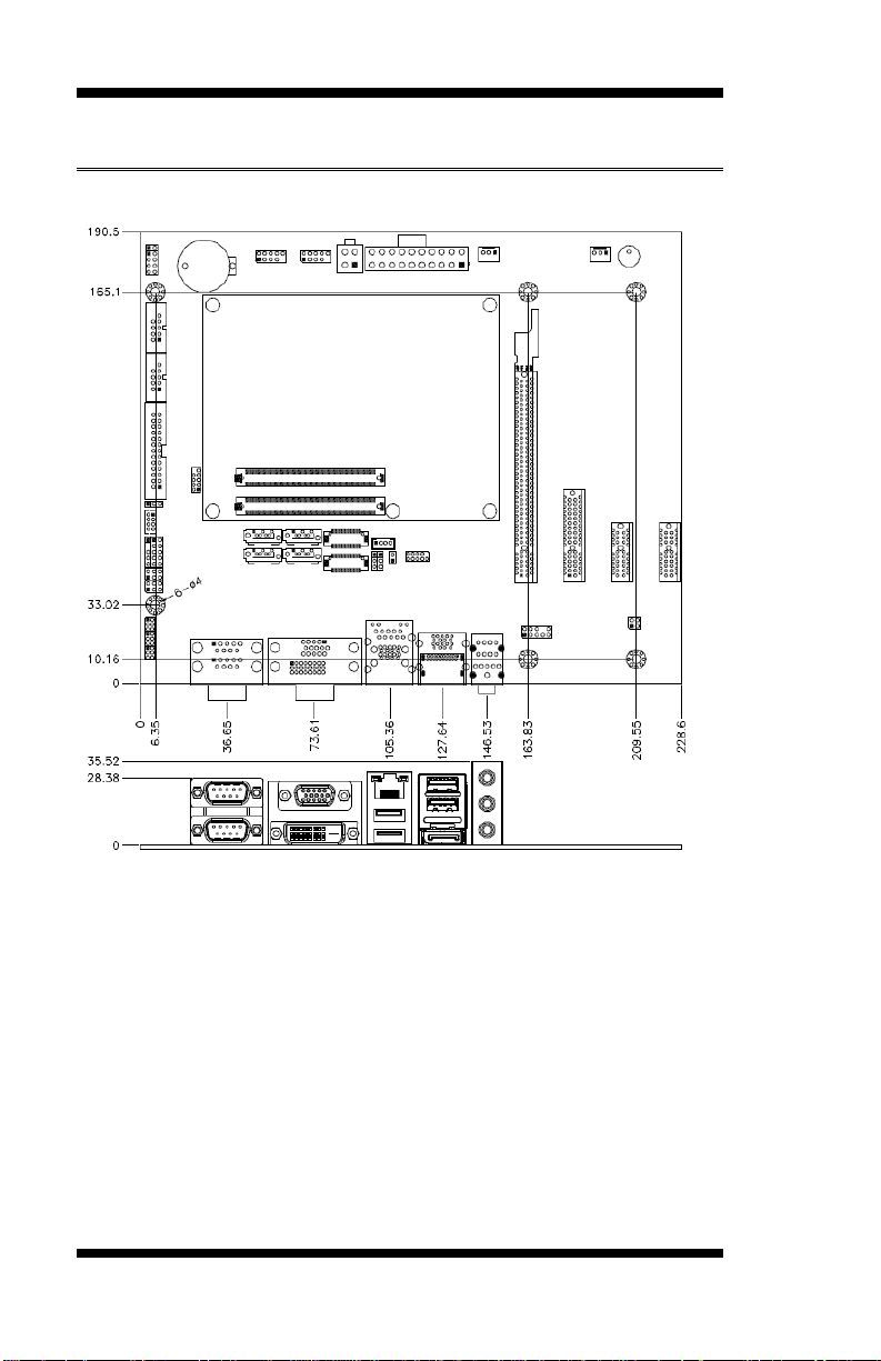
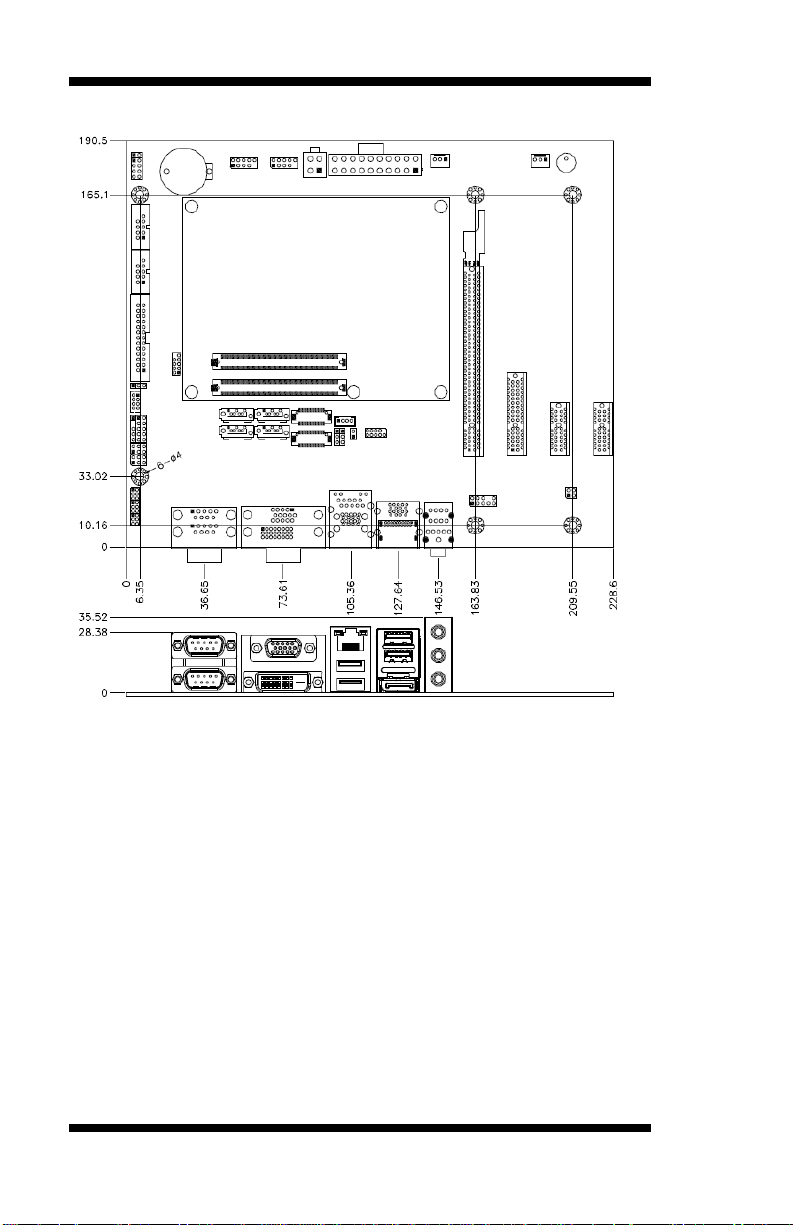
INTRODUCTION
Board Dimensions
2
IP402 User’s Manual
Page 7

INSTALLATIONS
Installations
This section provides information on how to use the jumpers and
connectors on the IP402 in order to set up a workable system. The topics
covered are:
Installing the CPU Module ................................................................... 4
Setting the Jumpers .............................................................................. 5
Connectors on IP402 ......................................................................... 10
IP402 User’s Manual 3
Page 8

INSTALLATIONS
Installing the CPU Module
The IP402 board supports COM Express Type6 CPU module such as the
ET930. Below is a picture showing how the CPU module and the
heatsink should be installed on the IP402 baseboard. There are five holes
on the IP402 that can be used to screw the three parts together – the
heatsink, the CPU module and the baseboard.
4
IP402 User’s Manual
Page 9

INSTALLATIONS
Setting the Jumpers
Jumpers are used on IP402 to select various settings and features
according to your needs and applications. Contact your supplier if you
have doubts about the best configuration for your needs. The following
lists the connectors on IP402 and their respective functions.
Jumper Locations on IP402.................................................................. 7
J4: AT/ATX Power Setting ................................................................. 8
J9: LVDS Panel Power ........................................................................ 8
J10: LVDS Backlight Power Setting .................................................... 8
J15: SPI Setting ................................................................................... 8
JP1, JP2, JP3: RS232/422/485 (COM1) Selection ................................ 9
JP4 :COM1 RS232 +5V/+12V Power Setting .................................... 10
JP5 :COM2 RS232 +5V/+12V Power Setting .................................... 10
JP6 : PS2 mouse/keyboard Power Setting ........................................ 10
IP402 User’s Manual 5
Page 10

INSTALLATIONS
Jumper Locations on IP402
6
IP402 User’s Manual
Page 11

J4
Power Type
Open
ATX
(Default)
Close
AT
J9
LVDS Panel Power
+3.3V (default)
+5V
J10
Power
+3.3V (default)
+5V
J15
BOOT
Main Board (default)
Baseboard
J4: AT/ATX Power Setting
J9: LVDS Panel Power
J10: LVDS Backlight Power Setting
INSTALLATIONS
J15: SPI Setting
IP402 User’s Manual 7
Page 12

INSTALLATIONS
COM1
Function
RS-232
RS-422
RS-485
Jumper
Setting
(pin closed)
JP1:
3-5 & 4-6
JP3:
3-5 & 4-6
JP2:
1-2
JP1:
1-3 & 2-4
JP3:
1-3 & 2-4
JP2:
3-4
JP1:
1-3 & 2-4
JP3:
1-3 & 2-4
JP2:
5-6
JP1, JP2, JP3: RS232/422/485 (COM1) Selection
COM2~COM4 are fixed for RS-232 use only.
COM1 is selectable for RS232, RS-422 and RS-485.
The following table describes the jumper settings for COM1
selection.
8
IP402 User’s Manual
Page 13

JP4
Setting
Function
Pin 1-3
Short/Closed
+12V
Pin 3-4
Short/Closed
Normal
Pin 3-5
Short/Closed
+5V
JP5
Setting
Function
Pin 1-3
Short/Closed
+12V
Pin 3-4
Short/Closed
Normal
Pin 3-5
Short/Closed
+5V
JP6
Setting
Function
Pin 1-2
Short/Closed
+5VSB
Pin 2-3
Short/Closed
+5V
JP4: COM1 RS232 +5V/+12V Power Setting
JP5: COM2 RS232 +5V/+12V Power Setting
JP6: PS2 mouse/keyboard Power Setting
INSTALLATIONS
IP402 User’s Manual 9
Page 14

INSTALLATIONS
Connectors on IP402
The connectors on IP402 allows you to connect external devices such as
keyboard, floppy disk drives, hard disk drives, printers, etc. The following
table lists the connectors on IP402 and their respective functions.
Connector Locations on IP402 .......................................................... 11
J2: PS/2 Keyboard and PS/2 Mouse Connectors ................................ 13
CN11: Audio Connector .................................................................... 13
J13: Audio Pin Header for Chassis Front Panel .................................. 13
J6(COM3),J5(COM4): Serial Ports .................................................... 14
J12: ATX Power Supply Connector ................................................... 14
J8 : ATX 12V Power Connector ........................................................ 14
JP10 : Panel Inverter Power Connector .................................................... 14
CN7 (CH1), CN8 (CH2): LVDS Connector ...................................... 15
RECS1, RECS2: COM Express Connector ........................................ 15
JP8, JP7: USB4/5, USB6/7 Port Pin Header ...................................... 15
JP13: SPDIF In/Out Connector.......................................................... 16
J7: Digital I/O .................................................................................... 16
J3: System Function Connector .......................................................... 16
J1: IrDA Connector ........................................................................... 16
LPT: Parallel Port Connector ............................................................. 17
CPU_FAN: CPU Fan Power Connector ............................................. 17
SYS_FAN: System Fan Power Connector ........................................ 17
10
IP402 User’s Manual
Page 15

Connector Locations on IP402
INSTALLATIONS
IP402 User’s Manual 11
Page 16

INSTALLATIONS
Signal Name
Pin #
Pin #
Signal Name
5V
1 2 5V
Mouse data
3 4 Keyboard data
Mouse clock
5 6 Keyboard clock
GND
7 8 GND
COM1
Signal Name
Pin #
Pin #
Signal Name
DCD
1 6 DSR
RXD
2 7 RTS
TXD
3 8 CTS
DTR
4 9 RI
GND
5
10
Not Used
Signal Name
Pin
Pin
Signal Name
MIC IN_L
1 2 Ground
MIC IN_R
3 4 DET
LINE_R
5 6 Ground
Sense
7 8 KEY
LINE_L
9
10
Ground
J2: PS/2 Keyboard and PS/2 Mouse Connectors
CN1A, CN1B: COM1(UP) and COM2(DOWN) Connector
CN4A, CN4B: VGA(UP) and DVI(DOWN) Connector
CN12: GbE_1 RJ-45 and USB2/3 Ports
CN15: DP and USB0/1 Ports
CN11: Audio Connector
The audio connector, from top to bottom, is composed of Line in, Line
out and Microphone jacks.
J13: Audio Pin Header for Chassis Front Panel
12
IP402 User’s Manual
Page 17

Signal Name
Pin #
Pin #
Signal Name
DCD, Data carrier detect
1 6 DSR, Data set ready
RXD, Receive data
2 7 RTS, Request to send
TXD, Transmit data
3 8 CTS, Clear to send
DTR, Data terminal ready
4 9 RI, Ring indicator
GND, ground
5
10
Not Used
11 1
20 10
Signal Name
Pin #
Pin #
Signal Name
3.3V
11 1 3.3V
-12V
12 2 3.3V
Ground
13 3 Ground
PS-ON
14 4 +5V
Ground
15 5 Ground
Ground
16 6 +5V
Ground
17 7 Ground
-5V
18 8 Power good
+5V
19 9 5VSB
+5V
20
10
+12V
Signal Name
Pin #
Pin #
Signal Name
+12V
3 1 Ground
+12V
4 2 Ground
Pin #
Signal Name
1
+12V
2
Backlight Enable
3
ADJ
4
Ground
J6(COM3),J5(COM4): Serial Ports
INSTALLATIONS
J12: ATX Power Supply Connector
J8 : ATX 12V Power Connector
JP10 : Panel Inverter Power Connector
IP402 User’s Manual 13
Page 18

INSTALLATIONS
Signal Name
Pin #
Pin #
Signal Name
TX0-
2 1 TX0+
Ground
4 3 Ground
TX1-
6 5 TX1+
5V/3.3V
8 7 Ground
TX3-
10 9 TX3+
TX2-
12
11
TX2+
Ground
14
13
Ground
TXC-
16
15
TXC+
5V/3.3V
18
17
ENABKL
VCC12
20
19
VCC12
Signal Name
Pin
Pin
Signal Name
Vcc
1 2 Vcc
D0-
3 4 D1-
D0+
5 6 D1+
Ground
7 8 Ground
Key Pin
9
10
NC
CN7 (CH1), CN8 (CH2): LVDS Connector
The LVDS connector supports single-channel 18-bit or 24-bit displays.
RECS1, RECS2: COM Express Connector
JP8, JP7: USB4/5, USB6/7 Port Pin Header
CN3,CN6: SATA2-IDE Connector
CN2,CN5: SATA3-IDE Connector
PCIEX1-1,PCIEX1-2: PCI- E(x1) Connector
PCIEX4-1,: PCI- E(x4) Connector
PCIEX16-1,: PCI- E(x16) Connector
14
IP402 User’s Manual
Page 19

INSTALLATIONS
Pin #
Signal Name
1
SPDIF IN
2
Ground
3
SPDIF OUT
4
Ground
Signal Name
Pin
Pin
Signal Name
GND
1 2 VCC
OUT3
3 4 OUT1
OUT2
5 6 OUT0
IN3
7 8 IN1
IN2
9
10
IN0
Signal Name
Pin #
Pin #
Signal Name
Power BTN
1 2 Power BTN
HDD LED+
3 4 HDD LED-
Reset BTN
5 6 Reset BTN
Power LED+
7 8 Power LED-
Pin #
Signal Name
1
+5V
2
No connect
3
Ir RX
4
Ground
5
Ir TX
JP13: SPDIF In/Out Connector
J7: Digital I/O
J3: System Function Connector
J3 provides connectors for system indicators that provide light indication
of the computer activities and switches to change the computer status. J3
is a 8-pin header that provides interfaces for the following functions.
J1: IrDA Connector
IP402 User’s Manual 15
Page 20

INSTALLATIONS
Signal Name
Pin #
Pin #
Signal Name
Line printer strobe
1
14
AutoFeed
PD0, parallel data 0
2
15
Error
PD1, parallel data 1
3
16
Initialize
PD2, parallel data 2
4
17
Select
PD3, parallel data 3
5
18
Ground
PD4, parallel data 4
6
19
Ground
PD5, parallel data 5
7
20
Ground
PD6, parallel data 6
8
21
Ground
PD7, parallel data 7
9
22
Ground
ACK, acknowledge
10
23
Ground
Busy
11
24
Ground
Paper empty
12
25
Ground
Select
13
26
N/A
Pin #
Signal Name
1
Ground
2
+12V
3
Rotation detection
Pin #
Signal Name
1
Ground
2
+12V
3
NC
LPT: Parallel Port Connector
CPU_FAN: CPU Fan Power Connector
SYS_FAN: System Fan Power Connector
16
IP402 User’s Manual
 Loading...