

Page 1
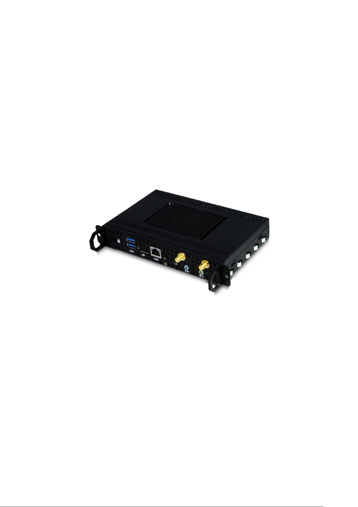
iOPS-76 Series
User Manual
2012 Jul V1
Page 2

Copyright © 2012 IBASE Technology INC. All Rights Reserved.
No part of this manual, including the products and software described in it, may be
reproduced, transmitted, transcribed, stored in a retrieval system, or translated into
any language in any form or by any means, except documentation kept by the
purchaser for backup purposes, without the express written permission of IBASE
Technology INC. (“IBASE”).
Products and corporate names mentioned in this manual may or may not be
registered trademarks or copyrights of their respective companies, and are used for
identification purposes only. All trademarks are the property of their respective
owners.
Every effort has been made to ensure that the contents of this manual are correct and
up to date. However, the manufacturer makes no guarantee regarding the accuracy of
its contents, and reserves the right to make changes without prior notice.
2
Page 3

Table of Contents
Safety Information ................................................................................................. 4
Setting up your system ................................................................................................. 4
Care during use ............................................................................................................ 4
Acknowledgments ........................................................................................................ 5
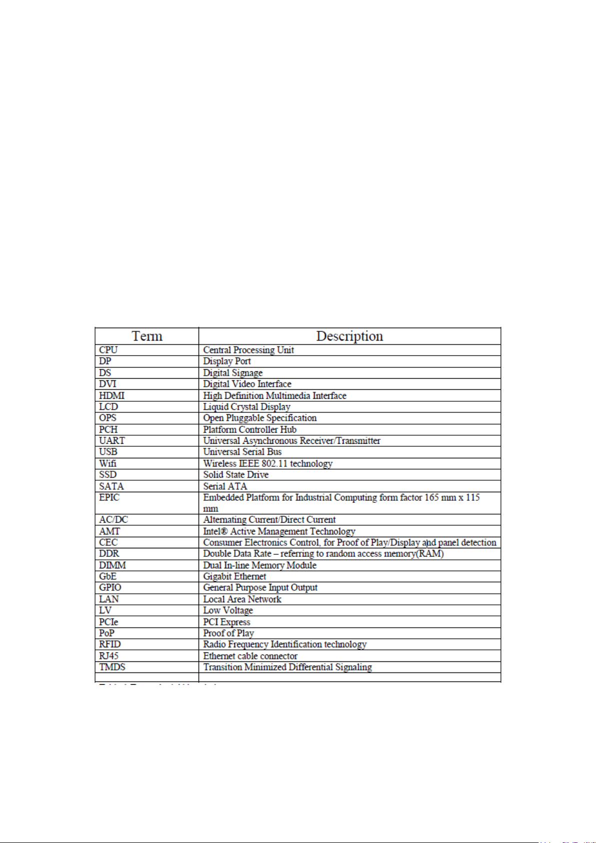
Table : Terms and Abbreviation ..................................................................................... 6
Accessories ............................................................................................................. 7
Components ........................................................................................................... 7
I/O View ...................................................................................................................... 7
System Specification ............................................................................................... 8
Mechanical Specification ........................................................................................ 9
Assembly iOPS-76 series to the OPS display ............................................................ 9
Intel® Open Pluggable Specification ............................................................................ 10
JAE connector features ............................................................................................... 10
iOPS-76 + iOPS-EK1 ..................................................................................................... 11
iOPS-76 + iOPS-EK2 ..................................................................................................... 11
Exploded view of the iOPS-76 assembly ................................................................ 12
Parts description ........................................................................................................ 12
Installation ........................................................................................................... 12
Installing the memory ................................................................................................ 12
Signal Description ................................................................................................ 13
Signal definitions ........................................................................................................ 14
Drivers Installation ............................................................................................... 17
3
Page 4

Safety Information
Your SI-38 is designed and tested to meet the latest standards of safety for
information technology equipment. However, to ensure your safety, it is important that
you read the following safety instructions.
Setting up your system
Read and follow all instructions in the documentation before you operate your
system.
Do not use this product near water.
Set up the system on a stable surface. Do not secure the system on any unstable
plane.
Do not place this product on an unstable cart, stand, or table. The product may
fall, causing serious damage to the product.
Slots and openings on the chassis are for ventilation. Do not block or cover these
openings. Make sure you leave plenty of space around the system for ventilation.
Never insert objects of any kind into the ventilation openings.
This system should be operated from the type of power indicated on the marking
label. If you are not sure of the type of power available, consult your dealer or
local power company.
Use this product in environments with ambient temperatures between 0˚C and
45˚C.
If you use an extension cord, make sure that the total ampere rating of the
devices plugged into the extension cord does not exceed its ampere rating.
DO NOT LEAVE THIS EQUIPMENT IN AN ENVIRONMENT WHERE
THESTORAGE TEMPERATURE MAY GO BELOW -20° C (-4° F) OR ABOVE
80° C (176° F). THIS COULD DAMAGE THE EQUIPMENT. THE EQUIPMENT
SHOULD BE IN A CONTROLLED ENVIRONMENT.
Care during use
Do not walk on the power cord or allow anything to rest on it.
Do not spill water or any other liquids on your system.
When the system is turned off, a small amount of electrical current still flows.
4
Page 5

Always unplug all power, and network cables from the power outlets before
cleaning the system.
If you encounter the following technical problems with the product, unplug the
power cord and contact a qualified service technician or your retailer.
The power cord or plug is damaged.
Liquid has been spilled into the system.
The system does not function properly even if you follow the operating
instructions.
The system was dropped or the cabinet is damaged.
CAUTION: Danger of explosion if battery is incorrectly replaced. Replace only with
the same or equivalent type recommended by the manufacturer. Dispose of used
batteries according to the manufacturer’s instructions.
The warranty does not apply to the products that have been disassembled by users
5
Page 6
Acknowledgments
AMI is a registered trademark of AMI Software International, Inc.
Intel are registered trademarks of Intel Corporation.
Microsoft Windows is a registered trademark of Microsoft Corporation.
FINTEK is a registered trademark of FINTEK Electronics Corporation.
REALTEK is a registered trademark of REALTEK Electronics Corporation.
All other product names or trademarks are properties of their respective owners.
Table : Terms and Abbreviation
6
Page 7
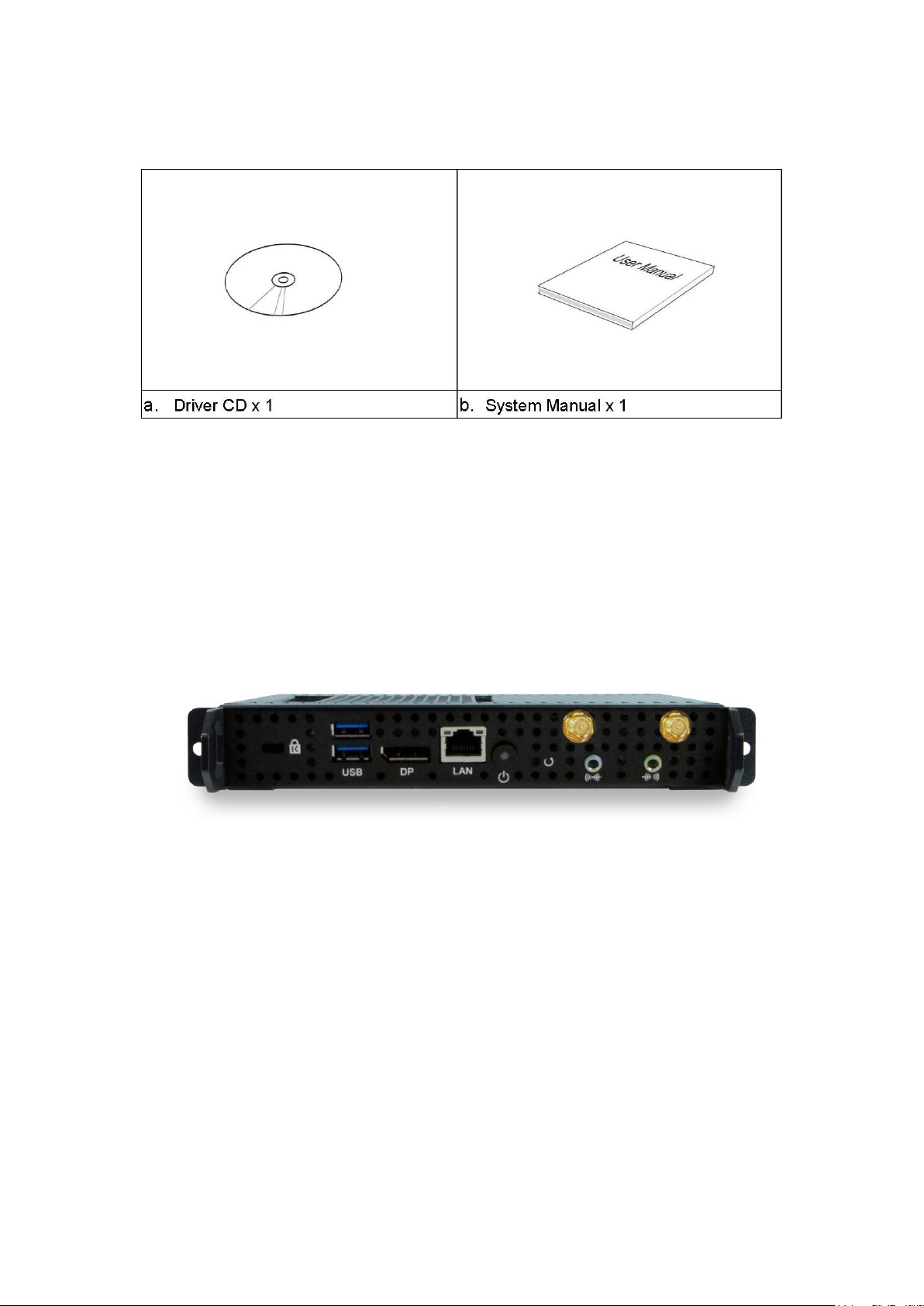
Accessories
Components
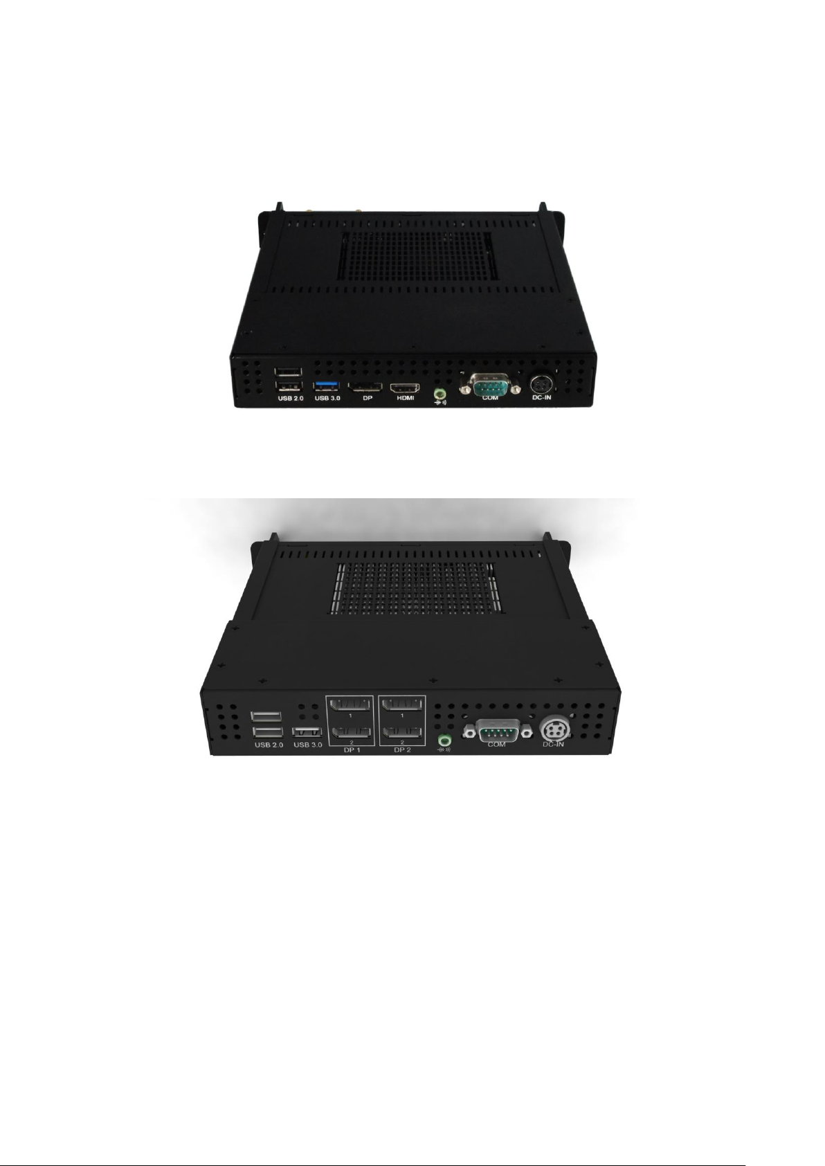
I/O View
Refer to the diagram below to identify the components on this side of the system.
Power Bottom
The power switch allows powering ON and OFF the system.
Power
The power bottom LED illuminated when system been power on.
Display Port
The Display Port interface is to transmitting uncompressed digital data.
LAN 1
The eight-pin RJ-45 LAN port supports a standard Ethernet cable for connection
7
Page 8

to a local network.
System Mainboard
IOPS-76 MB
Chassis Color
Black
Storage
64GB mSATA
Mounting
Open Pluggable Specification.
Power Supply
NA.
Operating Temperature
0°C ~ 45°C (32°F ~ 113°F)
Storage Temperature
-20°C ~ 80°C (-4°F~176°F)
Relative Humidity
5~90% @45°C (non-condensing)
Vibration
mSATA: 5 grms / 5~500Hz / random operation
Shock
mSATA: 15 Grms peak acceleration (11 msec duration)
RoHS
Available
USB1/2
The USB (Universal Serial Bus 3.0) port is compatible with USB devices such as
keyboards, mouse devices, cameras, and hard disk drives. USB allows many
devices to run simultaneously on a single computer, with some peripheral acting
as additional plug-in sites or hubs.
AUDIO
The stereo audio jack (3.5mm) is used to connect the system’s audio out signal to
amplified speakers or headphones.
System Specification
‧
This specification is subject to change without prior notice.
8
Page 9
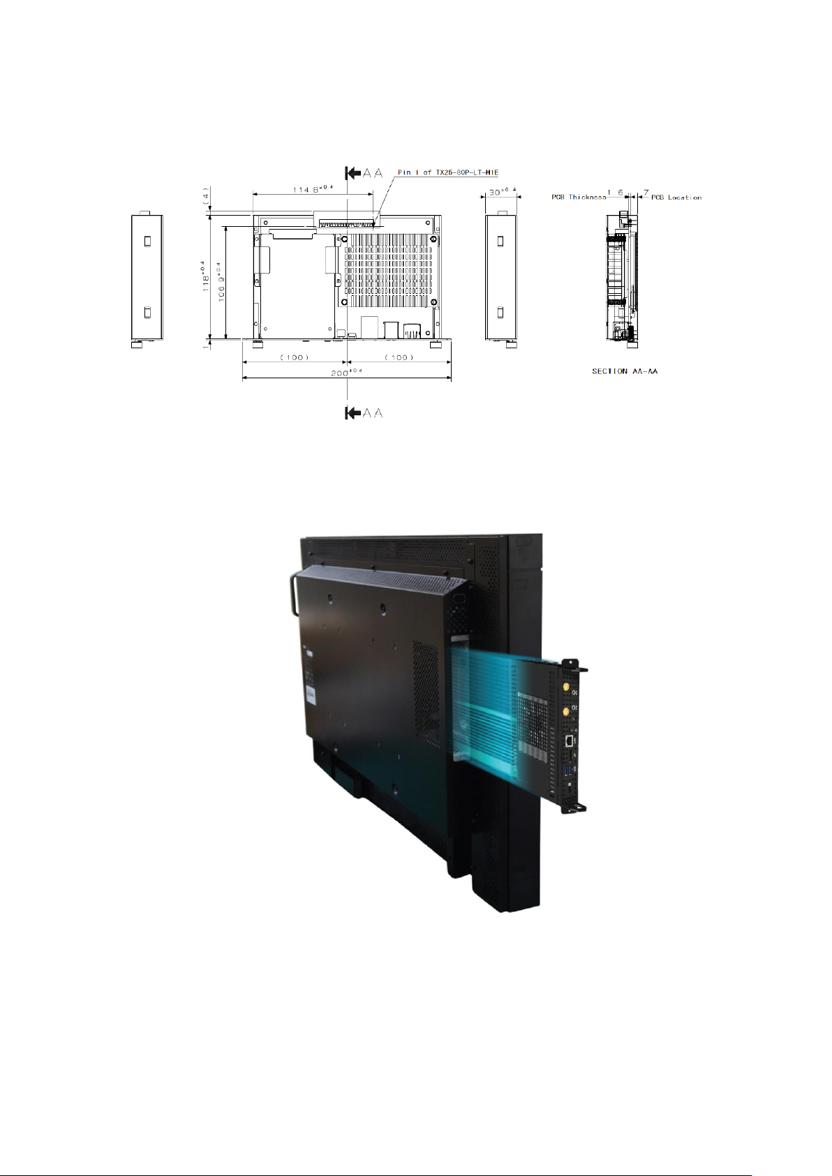
Mechanical Specification
Assembly iOPS-76 series to the OPS display
You can assembly iOPS-76 series into all OPS (Open Pluggable Specification)
display. It is follow Intel Open Pluggable Specification.
9
Page 10

Intel® Open Pluggable Specification
The Intel® Open Pluggable Specification (OPS) is an effort to standardize the
connector and signals between a slot PC and a digital signage display. This
allows for an open slot PC standard which can be adopted by display and PC
manufacturers, thereby enabling digital signage solutions that are more
cost-effective to deploy, maintain, and upgrade.
JAE connector features
The connector used for the Pluggable Module and docking board
Interconnect is based on the JAE TX24/TX25 family of plug and receptacle
connectors. The JAE connector pins are capable to support up to a max
current of 1A, for more detailed info please refer to the JAE connector
datasheet or contact JAE representative. The 80-pin right angle blindmate
plug connector (p/n: TX25-80P-LT-H1E) and its receptacle (p/n:
TX24-80R-LT-H1E) provide interfacing for the following features:
Power: DC IN +12V~+19V
Display Interface: DVI-D/TMDS and DisplayPort
Audio: Left and Right Channel
USB: 2*USB 2.0 and 1*USB 3.0
UART: Serial communication (Tx and Rx only)
Control Signals: Pluggable Module Power Status, Power ON via display panel,
Pluggable Board Detect, Consumer Electronics Control (CEC), and System
Fan Control..
I/O Expansion Platform
iOPS-EK1 –The iOPS-76 can easily connects with iOPS-EK1 expansion
dock through the JAE 80-pin connector, providing more I/O interface, and
allows it to serve as a stand-alone operating system..
iOPS-EK2 - The iOPS-EK2 features additional 4x DisplayPort interface,
making the iOPS-76 to become a multiple display solution (with 4,000 x
2,000 resolution support).
10
Page 11
iOPS-76 + iOPS-EK1
iOPS-76 + iOPS-EK2
11
Page 12

Exploded view of the iOPS-76 assembly
Part NO.
Description
Part NO.
Description
1
Front panel
2
Bottom cover
3
Main chassis
4
Memory modules
5
iOPS-76 MB
6
Heatsink module
7
Top cover
Parts description
Installation
Installing the memory
The IB938 board supports two DDR3 memory socket for a maximum total memory of
16GB in DDR3 SO-DIMM memory type. Installing and Removing Memory Modules
To install the DDR3 modules, locate the memory slot on the board and perform the
12
Page 13
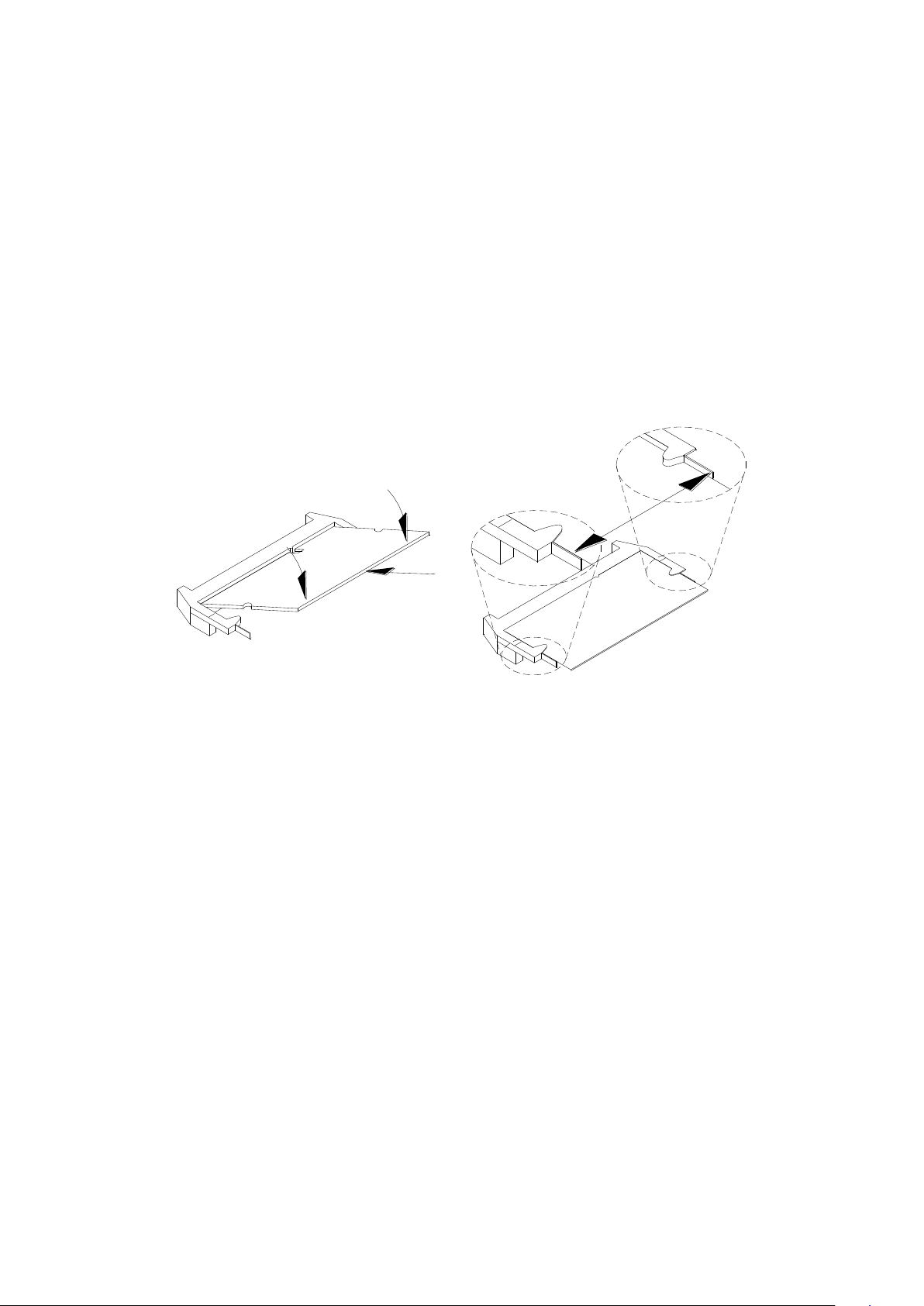
following steps:
1. Hold the DDR3 module so that the key of the DDR3 module aligns with that on
the memory slot. Insert the module into the socket at a slight angle
(approximately 30 degrees). Note that the socket and module are both keyed,
which means that the module can be installed only in one direction.
2. To seat the memory module into the socket, apply firm and even pressure to
each end of the module until you feel it slip down into the socket.
3. With the module properly seated in the socket, rotate the module downward.
Continue pressing downward until the clips at each end lock into position.
4. To remove the DDR3 module, press the clips with both hands.
Signal Description
This section provides a detailed description of each signal passing thru the JAE
connector. The signals are arranged in functional groups according to their associated
interface.
The “#” symbol at the end of the signal name indicates that the active or asserted
state occurs when the signal is at a low voltage level. When “#” is not present, the
signal is asserted when at the high voltage level.
The following notations are used to describe the signal type with regards to the
pluggable board:
I Input Pin
O Output Pin
OC Open Collector Output Pin.
The “Type” for each signal is indicative of the functional operating mode of the signal.
13
Page 14

Signal definitions
Power & Ground Signals
DVI-D Signals
14
Page 15

Display Port Signals
Audio Signals
USB Signals
UART Signals
15
Page 16

Control Signals
16
Page 17

Reserved Pins
Drivers Installation
This section describes the installation procedures for software and drivers. The software and drivers
are included with the motherboard. If you find the items missing, please contact the vendor where
you made the purchase. The contents of this section include the following:
IMPORTANT NOTE:
After installing your Windows operating system, you must install first the Intel Chipset Software
Installation Utility before proceeding with the drivers installation.
17
Page 18

Intel Chipset Software Installation Utility
The Intel Chipset Drivers should be installed first before the software drivers to enable Plug & Play
INF support for Intel chipset components. Follow the instructions below to complete the installation.
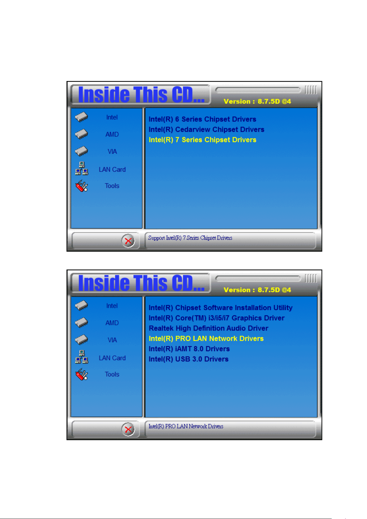
1. Insert the CD that comes with the board. Click Intel and then Intel(R) 7 Series Chipset Drivers..
2. Click Intel(R) Chipset Software Installation Utility.
18
Page 19

2. When the Welcome screen to the Intel® Chipset Device Software appears, click
Next to continue.
3. Click Yes to accept the software license agreement and proceed with the
installation process.
19
Page 20

4. Click Next to continue the installation process.
20
Page 21

5. On the Readme File Information screen, click Next to continue the installation.
6. The Setup process is now complete. Click Finish to restart the computer and for
changes to take effect.
21
Page 22

VGA Drivers Installation
NOTE: Before installing the Intel(R) Q77 Chipset Family Graphics Driver, the
Microsoft .NET Framework 3.5 SPI should be first installed.
To install the VGA drivers, follow the steps below.
1. Insert the CD that comes with the board. Click Intel and then Intel(R) Q7 Series
Chipset Drivers.
22
Page 23

2. Click Intel(R) Q77 Chipset Family Graphics Driver. DRIVERS INSTALLATION 54
3. When the Welcome screen appears, click Next to continue.
23
Page 24

4. Click Yes to to agree with the license agreement and continue the installation.
DRIVERS INSTALLATION
5. On the Readme File Information screen, click Next to continue the installation of
the Intel® Graphics Media Accelerator Driver.
24
Page 25

6. On Setup Progress screen, click Next to continue.
7. Setup complete. Click Finish to restart the computer and for changes to take effect.
DRIVERS INSTALLATION.
25
Page 26

Realtek HD Audio Driver Installation
Follow the steps below to install the Realtek HD Audio Drivers.
1. Insert the CD that comes with the board. Click Intel and then Intel(R) Q7 Series
Chipset Drivers.
2. Click Realtek High Definition Audio Driver. DRIVERS INSTALLATION
26
Page 27

3. On the Welcome to the InstallShield Wizard screen, click Next to proceed with and
complete the installation process.
4. The InstallShield Wizard Complete. Click Finish to restart the computer and for
changes to take effect. DRIVERS
INSTALLATION
27
Page 28
LAN Drivers Installation
1. Insert the CD that comes with the board. Click Intel and then Intel(R) Q7 Series
Chipset Drivers.
2. Click Intel(R) PRO LAN Network Driver. DRIVERS INSTALLATION
28
Page 29

3. Click Install Drivers and Software.
4. Click Next to to agree with the license agreement.
29
Page 30

5. Click the checkbox for Drivers in the Setup Options screen to select it and click
Next to continue. DRIVERS
INSTALLATION
6. The wizard is ready to begin installation. Click Install to begin the installation.
30
Page 31

7. When InstallShield Wizard is complete, click Finish. DRIVERS
INSTALLATION
8. When InstallShield Wizard is complete, click Finish.
31
Page 32

Intel® Management Engine Interface
Follow the steps below to install the Intel Management Engine.
1. Insert the CD that comes with the board. Click Intel and then Intel(R) AMT 8.0
Drivers. DRIVERS INSTALLATION
2. When the Welcome screen to the InstallShield Wizard for Intel® Management
Engine Components, click the checkbox for Install Intel® Control Center & click
Next.
32
Page 33

3. Click Yes to to agree with the license agreement. DRIVERS
INSTALLATION
33
Page 34

4. When the Setup Progress screen appears, click Next. Then, click Finish when the
setup progress has been successfully installed. DRIVERS
INSTALLATION
34
Page 35

Intel® USB 3.0 Drivers
1. Insert the CD that comes with the board. Click Intel and then Intel(R) Q7 Series
Chipset Drivers.
2. Click Intel(R) USB 3.0 Drivers. DRIVERS INSTALLATION
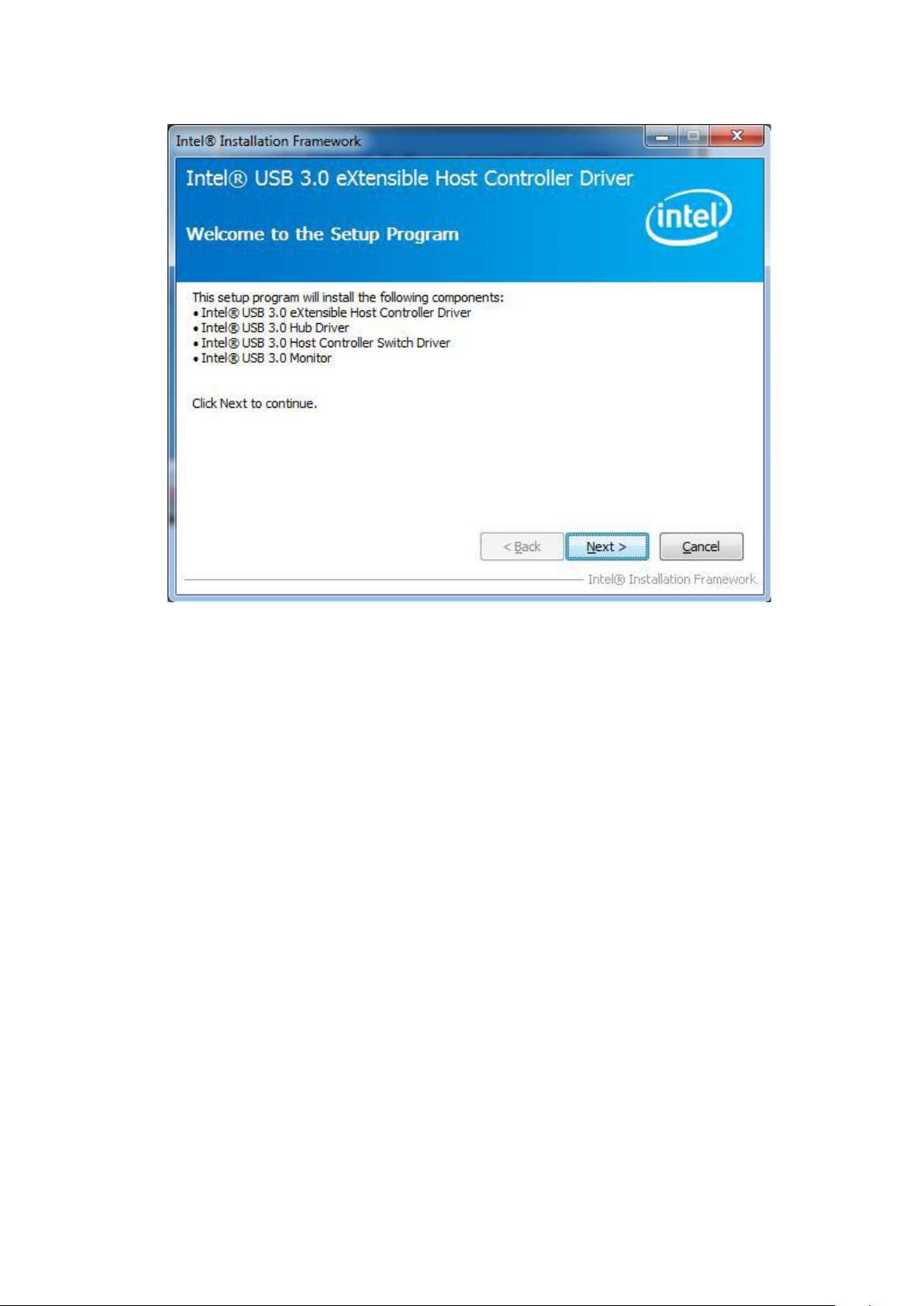
3. When the Welcome screen to the InstallShield Wizard for Intel® USB 3.0
eXtensible Host Controller Driver, click Next.
35
Page 36
4. Click Yes to to agree with the license agreement and continue the installation.
5. On the Readme File Information screen, click Next to continue the installation of
the Intel® USB 3.0 eXtensible Host Controller Driver.
6. Setup complete. Click Finish to restart the computer and for changes to take
effect.
36
 Loading...