

Page 1
www.ibase.com.tw
IBASE Technology Inc.
iOPS-18
User Manual
2013 Oct V1
Page 2

Page 3

1
iOPS-18 User Manual
Copyright © 2013 IBASE Technology Inc. All Rights Reserved.
No part of this manual, including the products and software described in it, may be
reproduced, transmitted, transcribed, stored in a retrieval system, or translated into
any language in any form or by any means, except documentation kept by the
purchaser for backup purposes, without the express written permission of IBASE
Technology INC. (“IBASE”).
Products and corporate names mentioned in this manual may or may not be
registered trademarks or copyrights of their respective companies, and are used for
identification purposes only. All trademarks are the property of their respective
owners.
Every effort has been made to ensure that the contents of this manual are correct and
up to date. However, the manufacturer makes no guarantee regarding the accuracy of
its contents, and reserves the right to make changes without prior notice.
Page 4

2
iOPS-18 User Manual
Table of Contents
Safety Information ................................................................................................. 3
Setting up your system........................................................................................ 3
Care during use ................................................................................................... 4
Acknowledgments .............................................................................................. 5
CHAPTER 1 INTRODUCTION .................................................................................... 6
1.1 General Description ...................................................................................... 6
1.2 System Specification ..................................................................................... 7
1.2.1 Hardware Specifications ......................................................................... 7
1.2.2 Dimensions ............................................................................................ 8
1.2.3 I/O View................................................................................................. 8
1.3 Exploded view of the iOPS-18 assembly ........................................................ 9
1.3.1 Parts description .................................................................................... 9
1.4 Packing List ..................................................................................................10
1.4.1 Optional items ......................................................................................10
1.5 HARDWARE INSTALLATION...........................................................................11
1.5.1 Memory Installation ..............................................................................11
1.5.2 Storage Installation................................................................................13
1.5.3 Wireless Installation ..............................................................................14
CHAPTER 2 MOTHERBOARD INTRODUCTION .........................................................15
2.1 Motherboard Introduction ...........................................................................16
2.2 Connector ....................................................................................................17
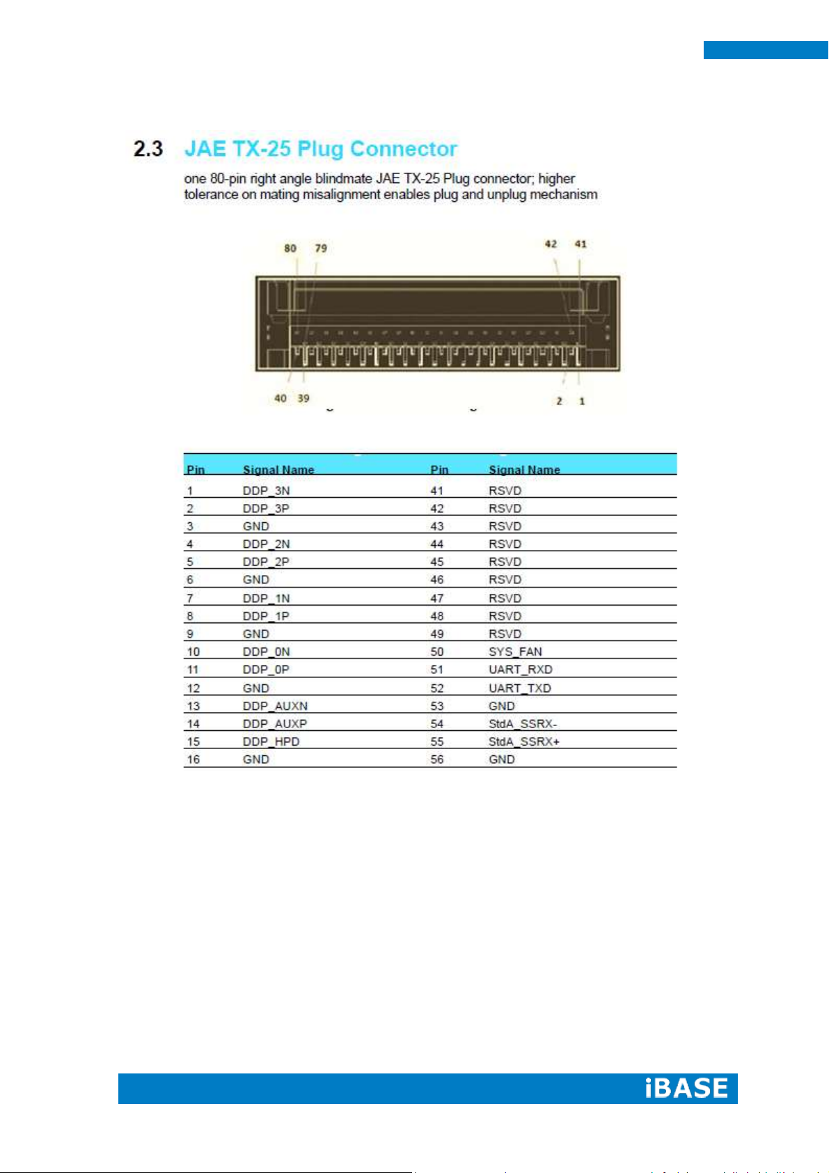
2.3 JAE TX-25 Plug Connector .............................................................................20
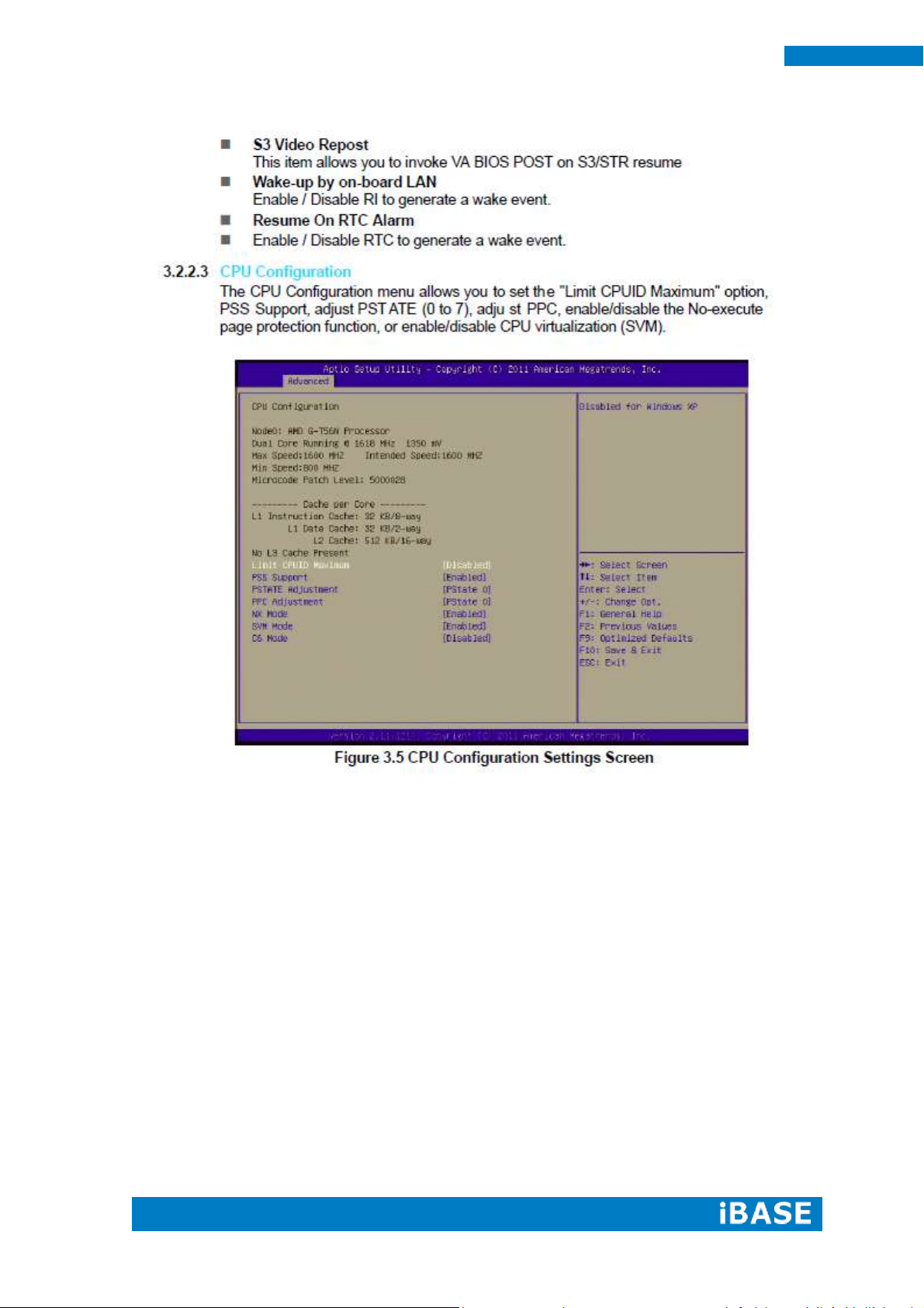
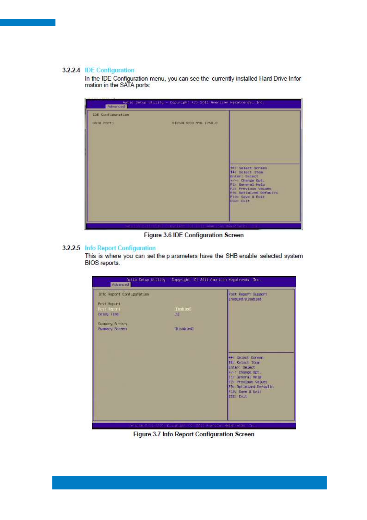
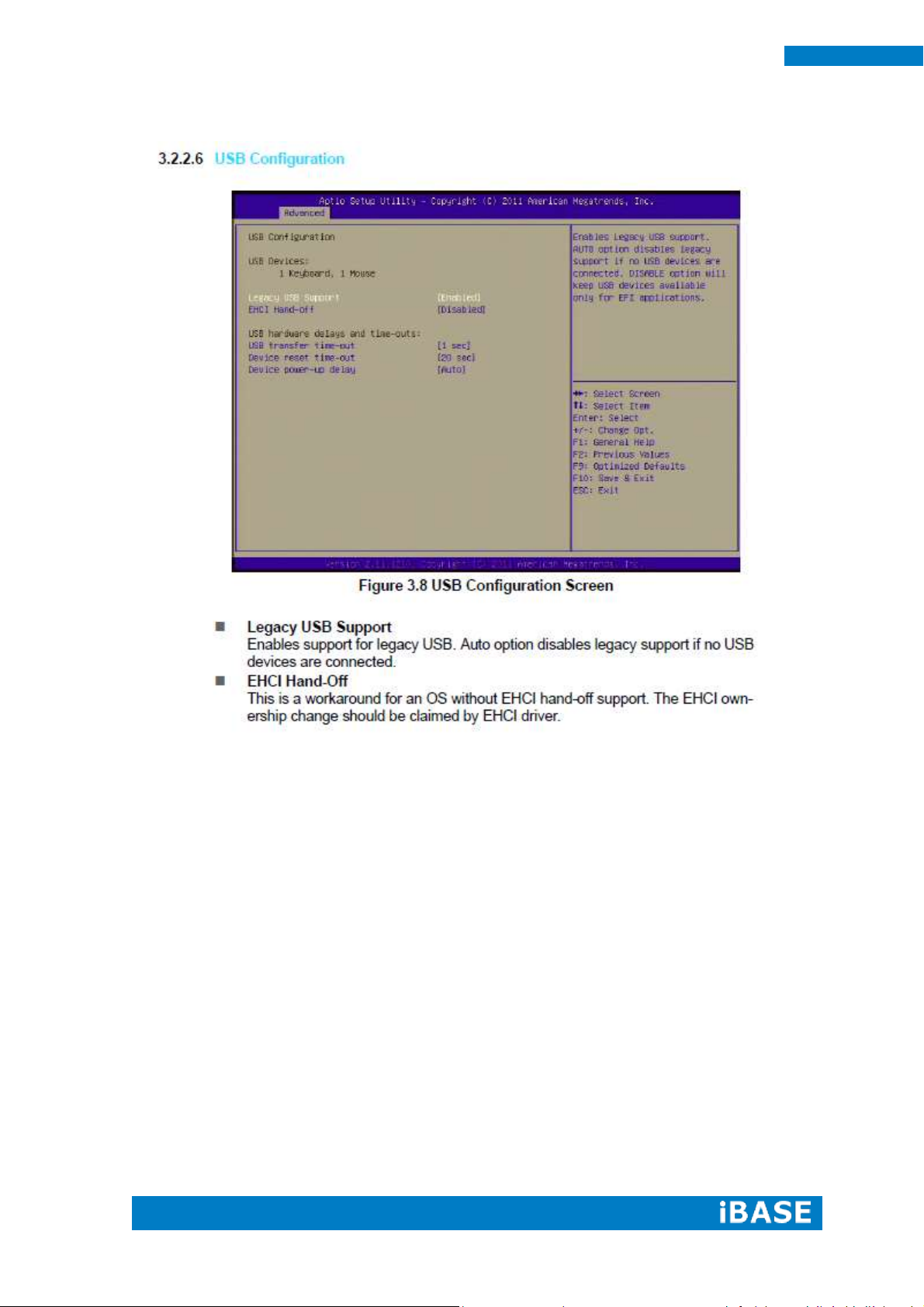
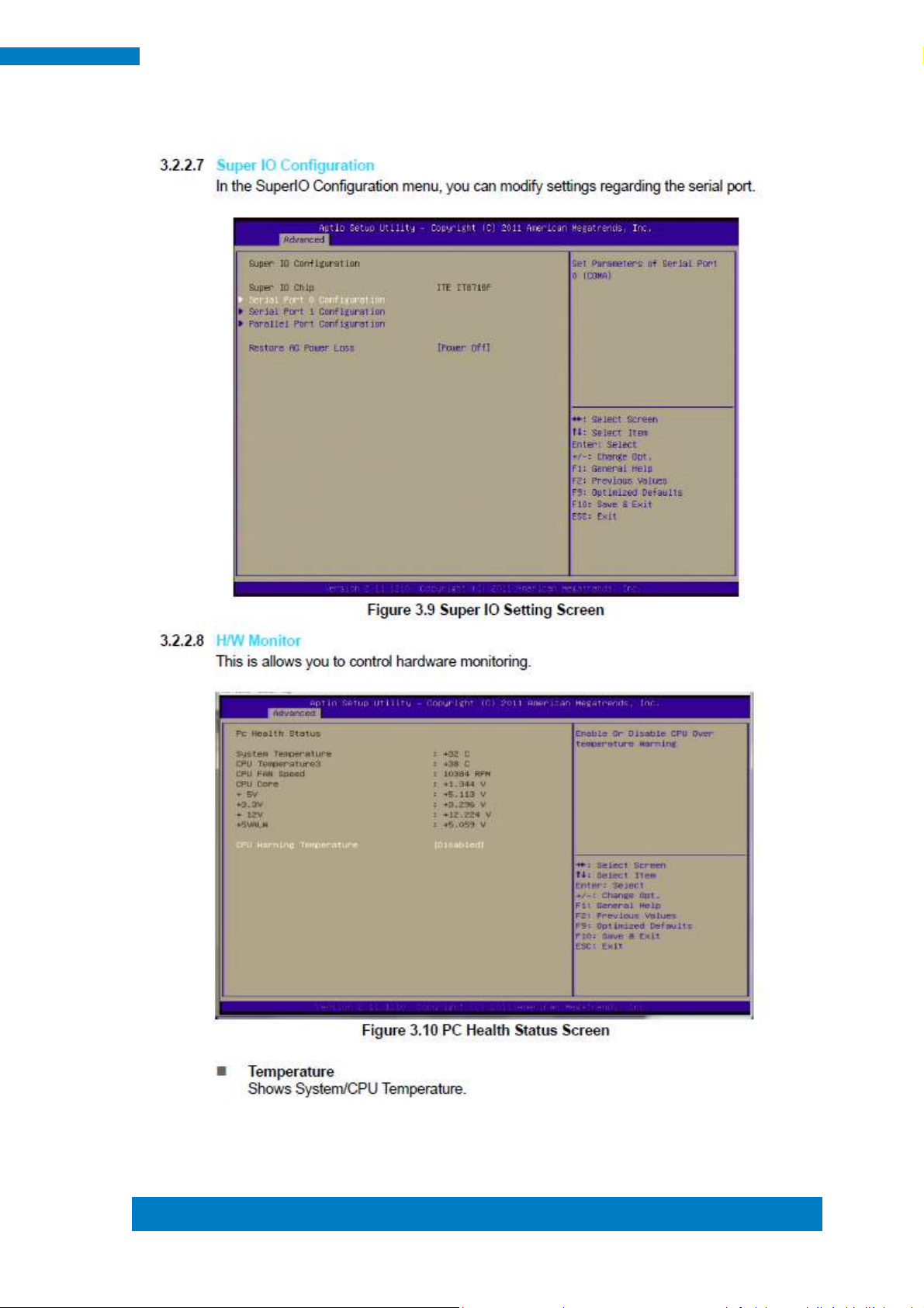
CHAPTER 3 BIOS SETUP .........................................................................................22
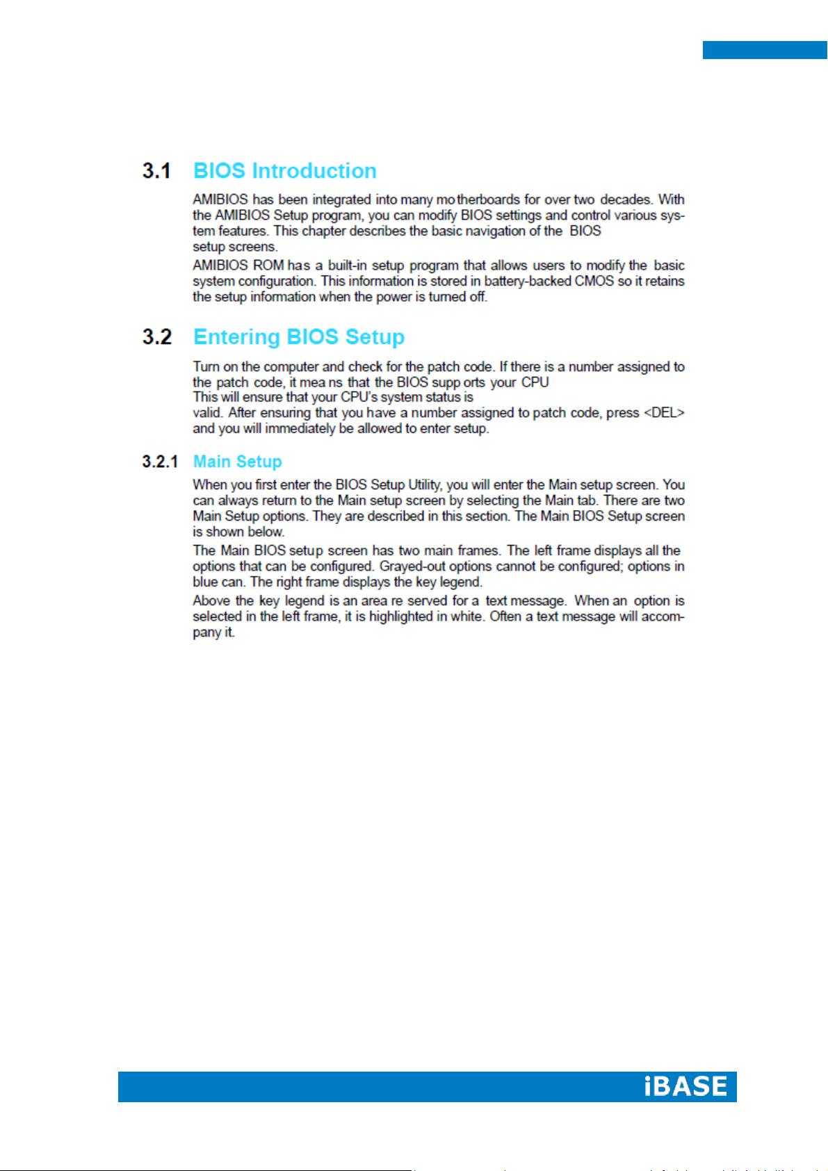
3.1 BIOS Introduction ........................................................................................22
3.2 Entering BIOS Setup .....................................................................................22
CHAPTER 4 DRIVERS INSTALLATION .......................................................................36
4.1 Driver Installation ........................................................................................36
4.1.1 Chipset and VGA Driver Installation .......................................................36
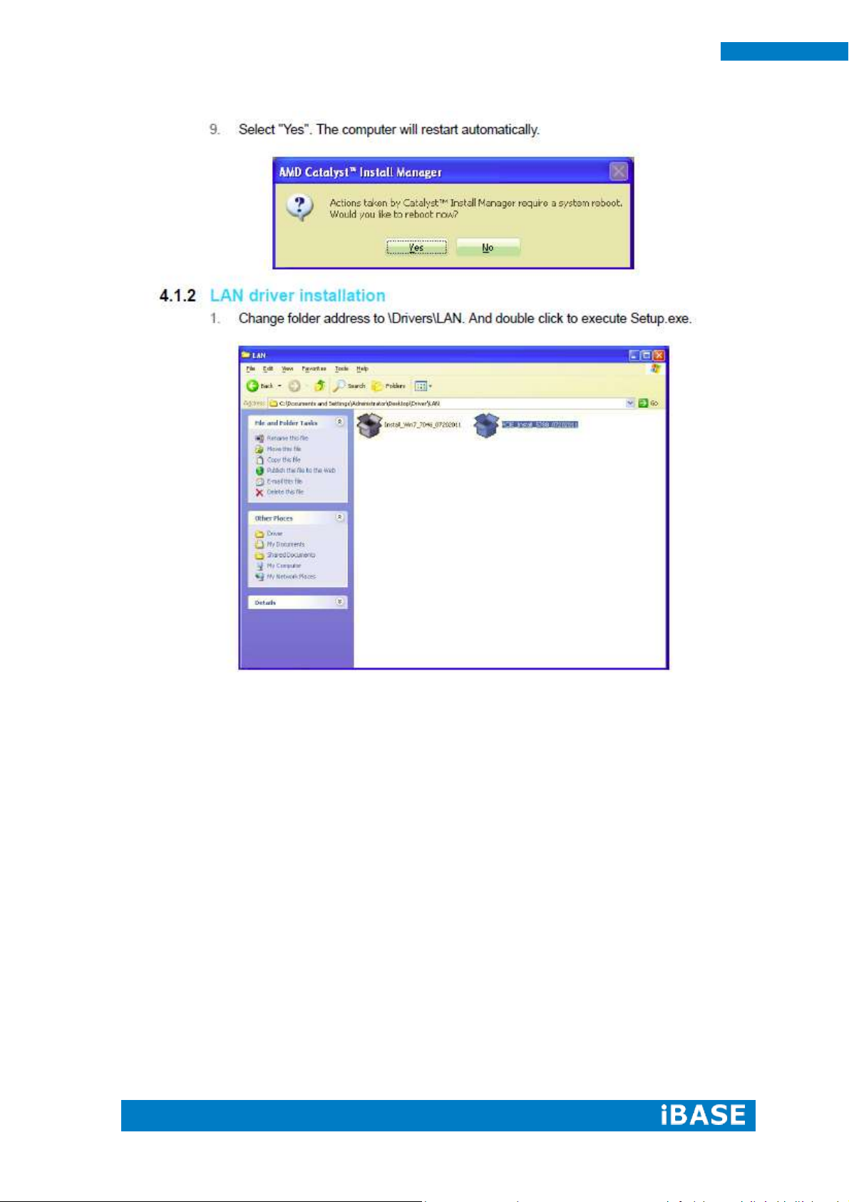
4.1.2 LAN Driver Installation ..........................................................................40
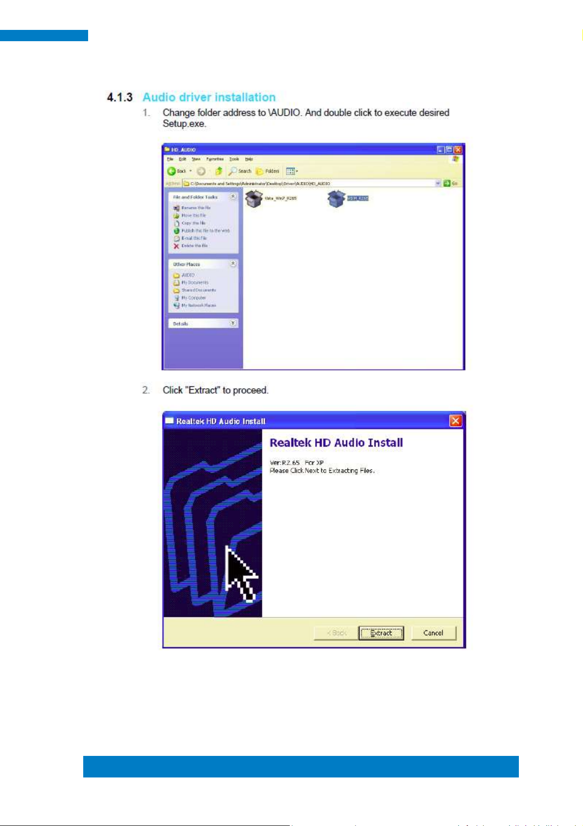
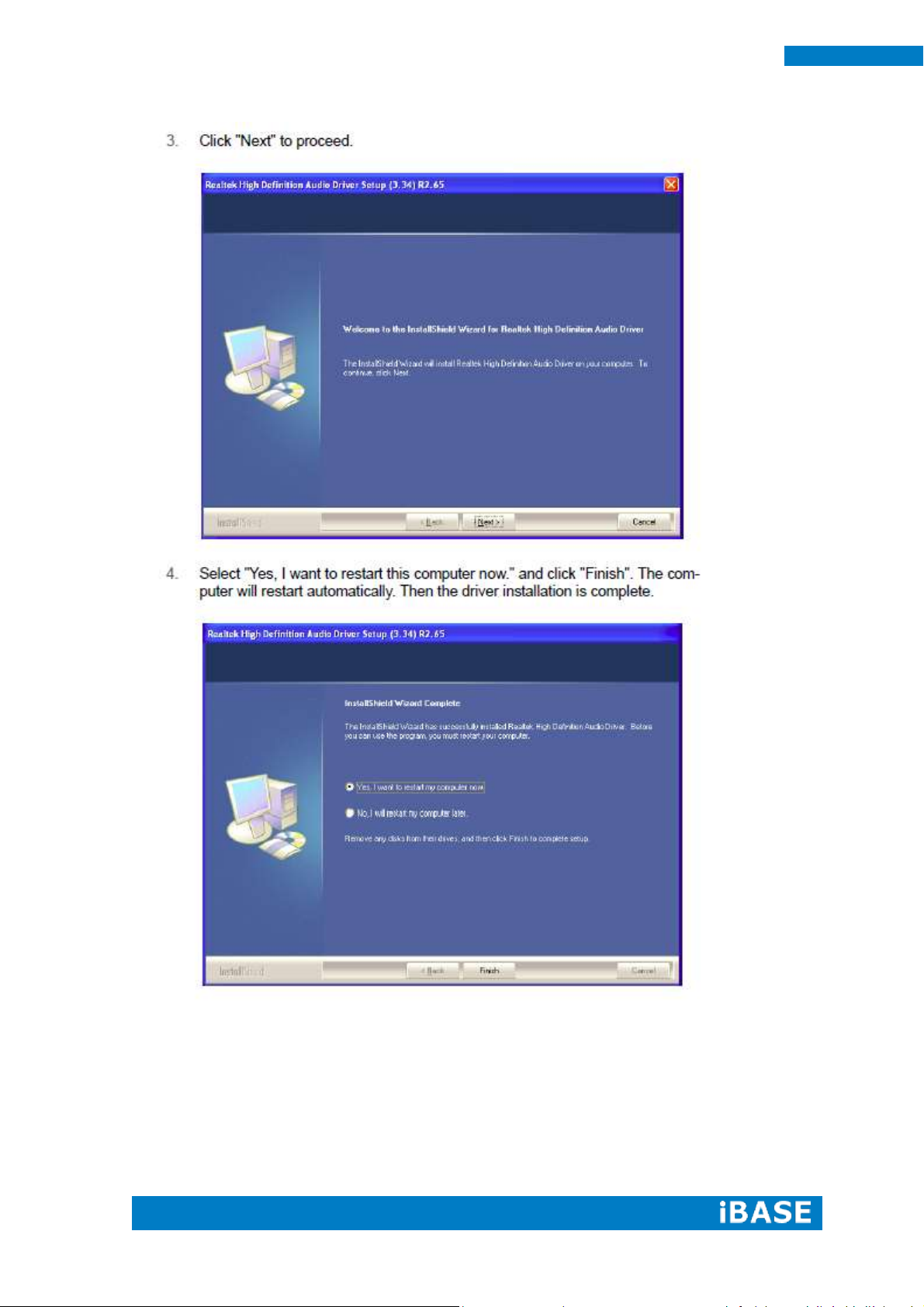
4.1.3 Audio Driver Installation .......................................................................43
Page 5

Copyright © 2013 IBASE Technology Inc. All Rights Reserved.
3
IBASE Technology Inc.
Safety Information
Your iOPS-18 is designed and tested to meet the latest standards of safety for
information technology equipment. However, to ensure your safety, it is important that
you read the following safety instructions.
Setting up your system
Read and follow all instructions in the documentation before you operate your
system.
Do not use this product near water.
Set up the system on a stable surface. Do not secure the system on any unstable
plane.
Do not place this product on an unstable cart, stand, or table. The product may
fall, causing serious damage to the product.
Slots and openings on the chassis are for ventilation. Do not block or cover these
openings. Make sure you leave plenty of space around the system for ventilation.
Never insert objects of any kind into the ventilation openings.
This system should be operated from the type of power indicated on the marking
label. If you are not sure of the type of power available, consult your dealer or
local power company.
Use this product in environments with ambient temperatures between 0˚C and
40˚C.
If you use an extension cord, make sure that the total ampere rating of the
devices plugged into the extension cord does not exceed its ampere rating.
DO NOT LEAVE THIS EQUIPMENT IN AN ENVIRONMENT WHERE
THESTORAGE TEMPERATURE MAY GO BELOW -20° C (-4° F) OR ABOVE
80° C (176° F). THIS COULD DAMAGE THE EQUIPMENT. THE EQUIPMENT
SHOULD BE IN A CONTROLLED ENVIRONMENT.
Page 6

4
iOPS-18 User Manual
Care during use
Do not walk on the power cord or allow anything to rest on it.
Do not spill water or any other liquids on your system.
When the system is turned off, a small amount of electrical current still flows.
Always unplug all power, and network cables from the power outlets before
cleaning the system.
If you encounter the following technical problems with the product, unplug the
power cord and contact a qualified service technician or your retailer.
The power cord or plug is damaged.
Liquid has been spilled into the system.
The system does not function properly even if you follow the operating
instructions.
The system was dropped or the cabinet is damaged.
Lithium-Ion Battery Warning
CAUTION: Danger of explosion if battery is incorrectly replaced. Replace only with
the same or equivalent type recommended by the manufacturer. Dispose of used
batteries according to the manufacturer’s instructions.
NO DISASSEMBLY
The warranty does not apply to the products that have been disassembled by users
WARNING
HAZARDOUS MOVING PARTS
KEEP FINGERS AND OTHER BODY PARTS AWAY
Page 7

Copyright © 2013 IBASE Technology Inc. All Rights Reserved.
5
IBASE Technology Inc.
Acknowledgments
AMI is a registered trademark of AMI Software International, Inc.
AMD and ATI are registered trademarks of AMD Corporation.
Microsoft Windows is a registered trademark of Microsoft Corporation.
FINTEK is a registered trademark of FINTEK Electronics Corporation.
REALTEK is a registered trademark of REALTEK Electronics Corporation.
All other product names or trademarks are properties of their respective owners.
Page 8
6
iOPS-18 User Manual
CHAPTER 1 INTRODUCTION
1.1 General Description
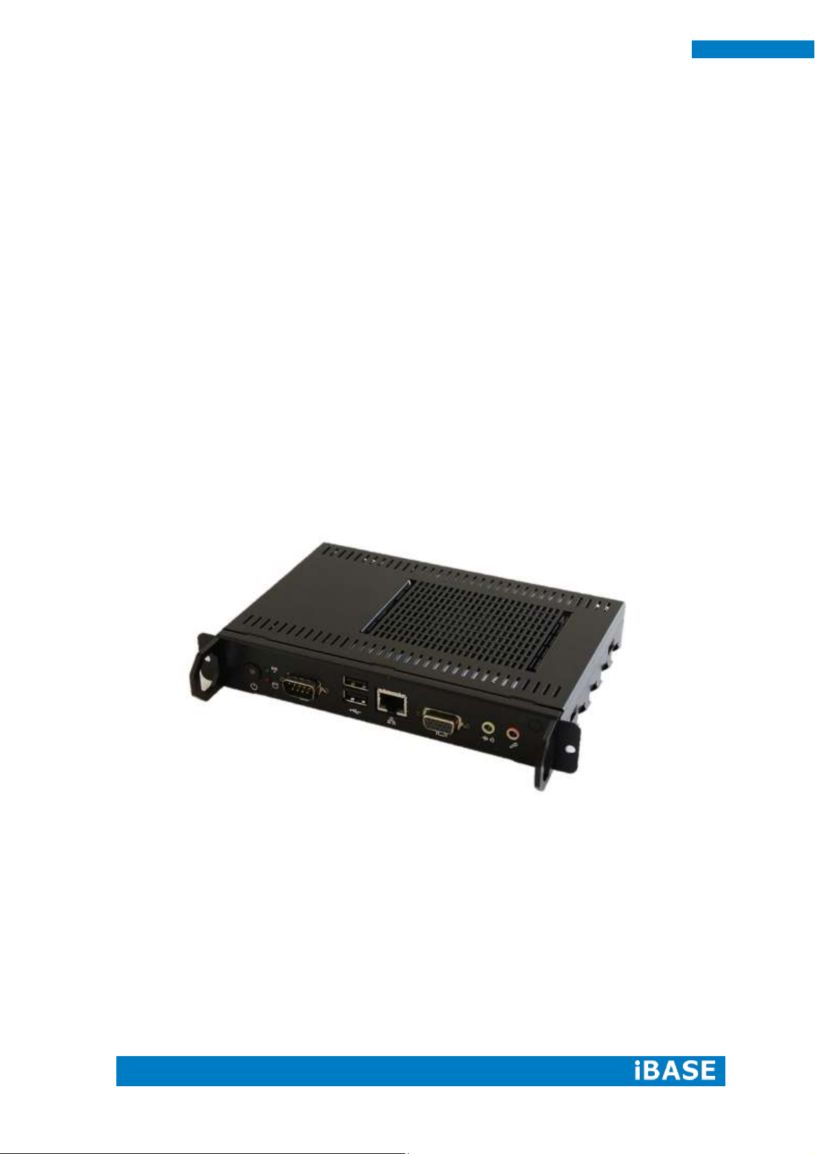
The OPS signage player iOPS-18 is an Open Pluggable Specification (OPS)
compliant signage player powered by the AMD G-Series Dual-Core APU T56N with
AMD A50M Controller Hub chipset. Compliant with the Open Pluggable Specification
(OPS), its slot-in module design effectively lowers deployment and field maintenance
costs to simplify device installation, usage, maintenance and upgrades. Its slot-in
module is connected via a JAE 80-pin connector, and includes the HDMI, DP, UART,
and USB2.0 signals. The player-screen communication interface via UART and HDMI
CEC provides status reporting and control, and also supports digital audio/video
signals via HDMI or display port, for picture-perfect content reproduction. Also
supports 1x Giga LAN, 1x COM ports, and 2x USB2.0 ports giving a great selection
for data communication in display applications. The entire design makes digital
signage applications more intelligent and connected.
Page 9
Copyright © 2013 IBASE Technology Inc. All Rights Reserved.
7
IBASE Technology Inc.
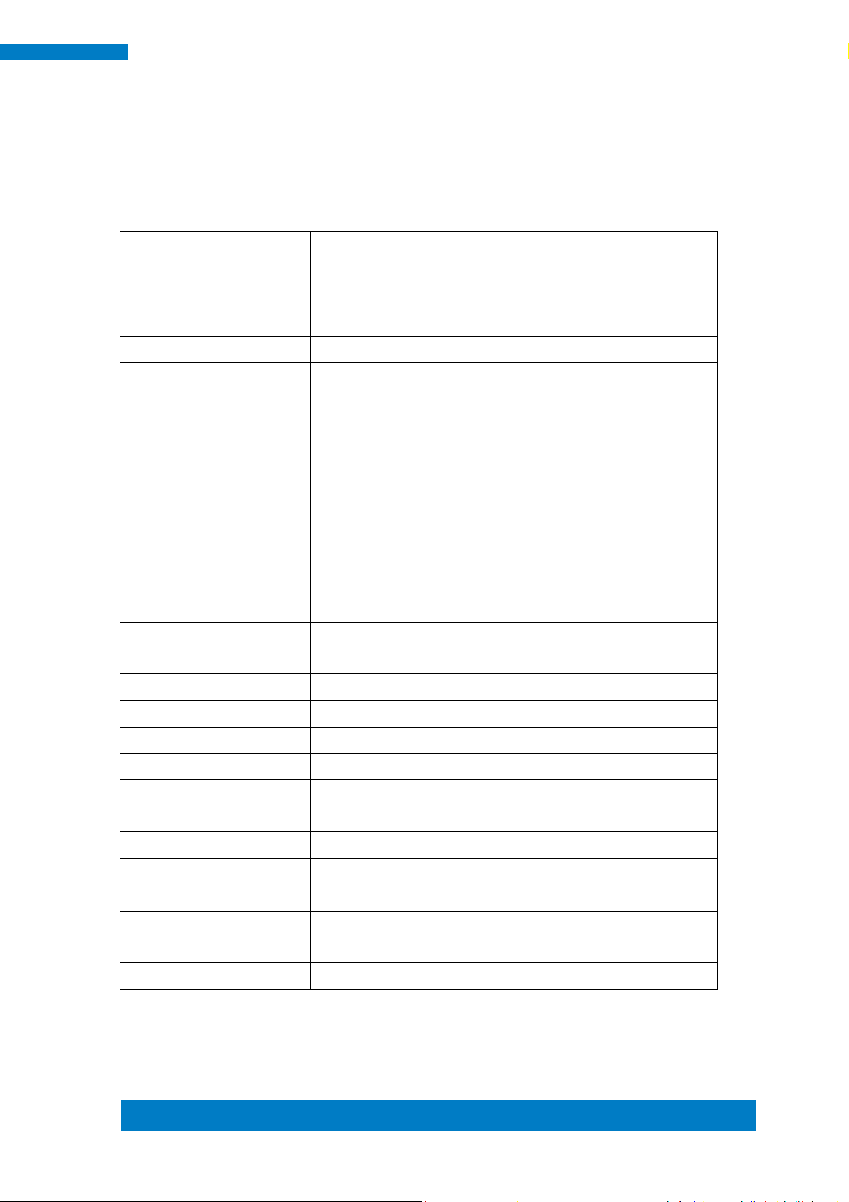
Model Name
iOPS-18
System Mainboard
iOPS-18MB
CPU
AMD G-Series Dual-Core APU (Accelerated Processing
Unit):T56N=1.65GHz @ 18W TDP
Chipset
AMD A50M Controller Hub
Memory
1 x DDR3 1333MHz SO-DIMM 204PIN (Max. 4GB)
I/O Interface
1 x OPS connector (JAE TX 25, Pin definition follow Intel
OPS Spec)
1 x D-Sub
1 x Gigabit LAN (RJ-45)
2 x USB2.0 compliant
1 x COM port (RS-232)
1 x Power button
1 x Line-In/Line-out
Storage
2.5” Open-frame SSD
Expansion Slots
1 x Mini PCI-E(x1) slot for Wi-Fi, Bluetooth, TV tuner
options
Power Supply
N/A
Construction
Aluminum + SGCC (steel)
Chassis Color
Black
Mounting
Open Pluggable Specification
Dimensions
200mm(W) x 119mm(D) x 30mm(H)
7.87"(W) x 4.69"(D) x 1.18"(H)
Operating Temperature
0°C~ 40°C (32°F~104°F)
Storage Temperature
-20° ~ 80°C (-4°F~176°F)
Relative Humidity
5~90% @ 45°C, (non-condensing)
Vibration
SSD: 5 grms / 5~500Hz / random operation
HDD: 0.25 grms / 5~500Hz / random operation
Certification
CE, FCC
1.2 System Specification
1.2.1 Hardware Specifications
‧
This specification is subject to change without prior notice.
Page 10
8
iOPS-18 User Manual
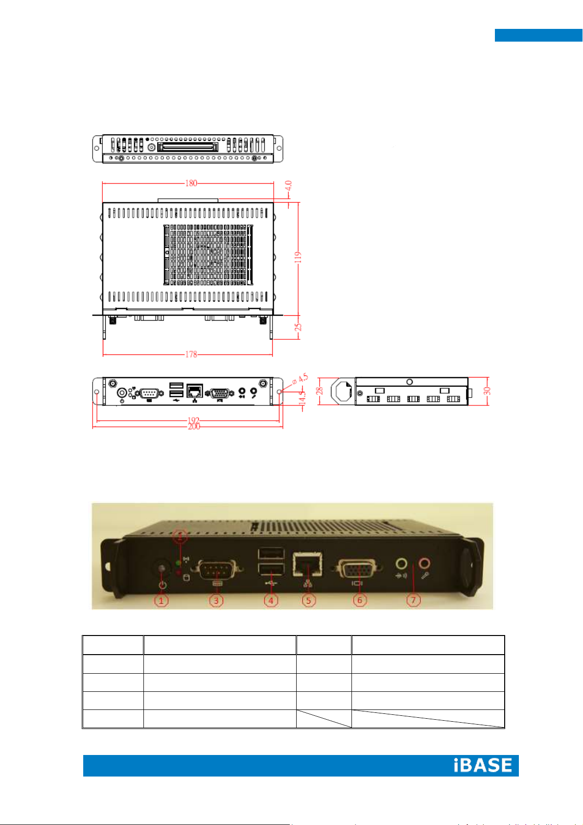
Part No.
Connector
Part No.
Connector
1
Power button
5
Gigabit LAN (RJ45)
2
Power/HDD LED Indicator
6
D-Sub
3
RS-232 COM port
7
Line-in/Line-out
4
2.0 USB port
1.2.2 Dimensions
1.2.3 I/O View
Page 11
Copyright © 2013 IBASE Technology Inc. All Rights Reserved.
9
IBASE Technology Inc.
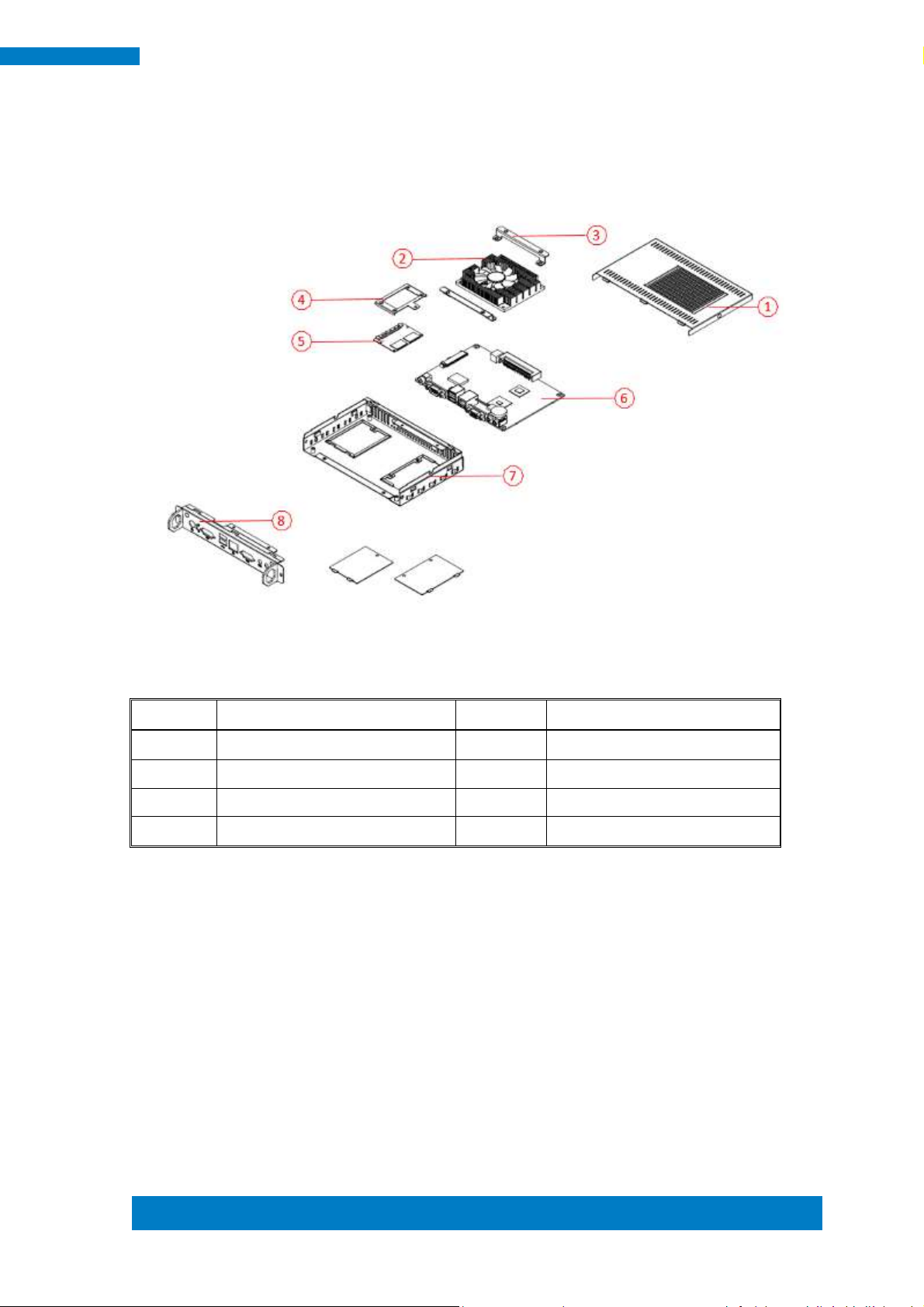
Part No.
Description
Part No.
Description
1
Top cover
2
Fan
3
Fan bracket
4
SSD bracket
5
SSD
6
iOPS-18MB
7
Base
8
I/O cover
1.3 Exploded view of the iOPS-18 assembly
1.3.1 Parts description
Page 12
10
iOPS-18 User Manual
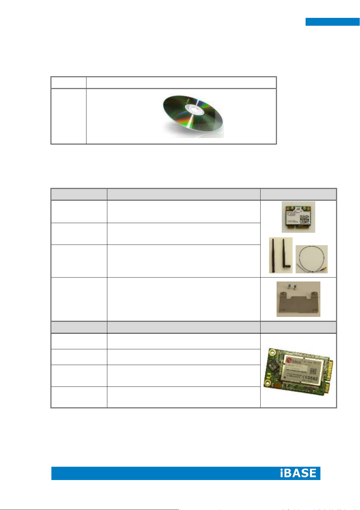
Part NO.
Description
1
Driver CD
Wifi solution
Description
Icon
QCOM wifi
module
Wireless LAN Card; 802.11 B/G/N+BT Half Card
[Q802XKN3B] RoHS (A008WIRELESS00700P)
External
Antenna
Wifi Antenna (A055RFA02C2M20800P)
Internal
cable-1/2
From Wifi module to Rear/Front panel
(A055RFA0000021000P/A055RFA0000032000P)
Bracket
MPCIE-EXT V-B1 Bracket, RoHS ;Extend Half to
Full size. (SC2MPCIEEXT0B1100P)
3G solution
Description
Icon
ZU 202
Wireless; 3.75G UMTS/HSPA [ZU202] RoHS
(A008WIRELESS00520P)
ZU 200
Wireless; 3.75G UMTS/HSPA AND GPS Module
[ZU200] RoHS (A008WIRELESS00510P)
Cable
Cable; Antenna-2 30CM P 2pcs
(C501ANT0200300000P)
Antenna
Antenna; 3G, 2pcs (A055ANT0921Q2P000P)
1.4 Packing List
1.4.1 Optional Items
Page 13
Copyright © 2013 IBASE Technology Inc. All Rights Reserved.
11
IBASE Technology Inc.
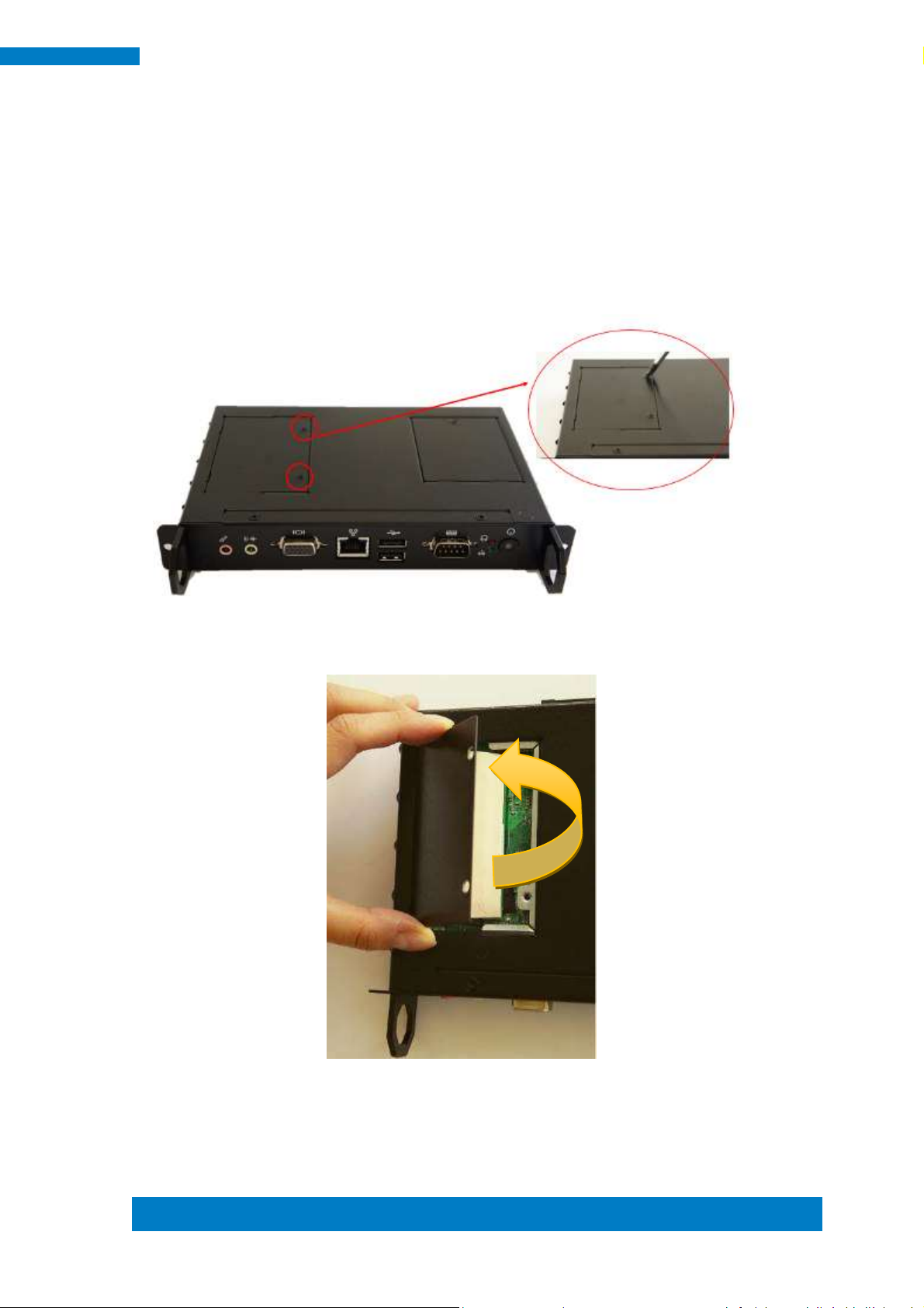
1.5 HARDWARE INSTALLATION
1.5.1 Memory Installation
1. Remove the back cover with two screws as in the picture.
2. Once the two screws are removed, lift the cover forward to remove it.
Page 14
12
iOPS-18 User Manual
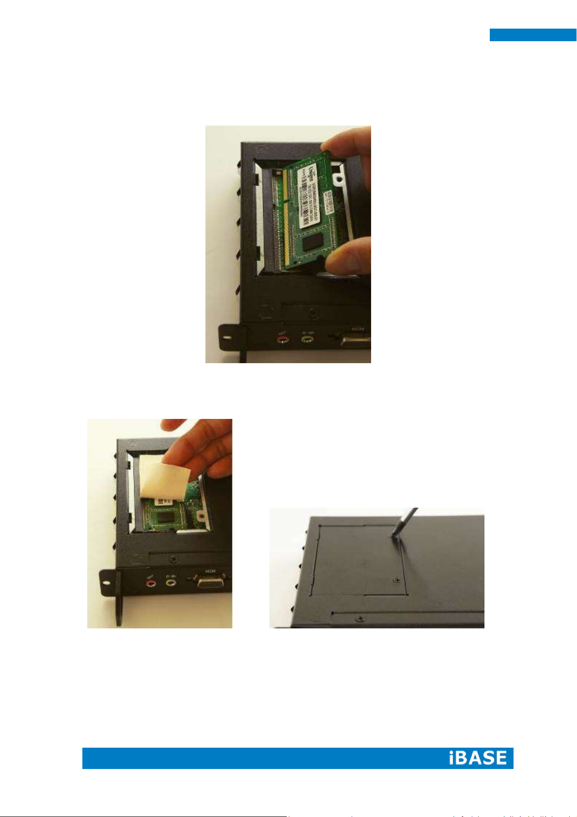
3. With the cover removed, locate the memory slots. Insert the module into the slot.
Apply firm pressure to the module until it slips into the slot. While pushing the
SO-DIMM into the position, the lock will close automatically.
4. Put the thermal pad on the memory module. Return the back cover and turn the
screws.
Page 15

Copyright © 2013 IBASE Technology Inc. All Rights Reserved.
13
IBASE Technology Inc.
1.5.2 Storage Installation
1. Use a screwdriver to turn the two screws to its unlocked position.
2. Remove the screw as in the picture and change the storage module.
Page 16

14
iOPS-18 User Manual
1.5.3 Wireless Installation
1. Remove the back cover with one screw as in the picture.
2. Insert the extending kit into the slot. Push the wifi module into the slot.
Page 17

Copyright © 2013 IBASE Technology Inc. All Rights Reserved.
15
IBASE Technology Inc.
3. Use a screwdriver to turn the two screws to its unlocked position.
4. The wifi module is fixed as in the picture.
Page 18

16
iOPS-18 User Manual
Model Name
iOPS-18MB
CPU
AMD G-Series, T56N Dual Core 1.6 GHz
Chipset
AMD G-Series + A50M FCH
Memory
1 x DDR3 1333MHz SO-DIMM 204PIN (Max. 4GB)
Graphic Chipset
AMD Radeon HD 6310
Display
HDMI/DP: (via OPS interconnection)
VGA
Storage
Support 2.5” SATA HDD/SSD
Ethernet
Realtek RTL8111E-VB-GR 10/100/1000Mbps
(1 x RJ-45)
Power Supply
Input Voltage: 12-24V (via OPS interconnection)
PWR Consumption
Ave 18W, Max 30W
OS Support
Windows7, Windows XP with SP3, Windows XP
Embedded, Linux
Board Dimension
165 x 115 mm
CHAPTER 2 MOTHERBOARD INTRODUCTION
2.1 Motherboard Introduction
Page 19

Copyright © 2013 IBASE Technology Inc. All Rights Reserved.
17
IBASE Technology Inc.
2.2 Connector
Page 20

18
iOPS-18 User Manual
Page 21

Copyright © 2013 IBASE Technology Inc. All Rights Reserved.
19
IBASE Technology Inc.
Page 22
20
iOPS-18 User Manual
Page 23

Copyright © 2013 IBASE Technology Inc. All Rights Reserved.
21
IBASE Technology Inc.
Page 24
22
iOPS-18 User Manual
CHAPTER 3 BIOS SETUP
Page 25
Copyright © 2013 IBASE Technology Inc. All Rights Reserved.
23
IBASE Technology Inc.
Page 26
24
iOPS-18 User Manual
Page 27

Copyright © 2013 IBASE Technology Inc. All Rights Reserved.
25
IBASE Technology Inc.
Page 28
26
iOPS-18 User Manual
Page 29
Copyright © 2013 IBASE Technology Inc. All Rights Reserved.
27
IBASE Technology Inc.
Page 30
28
iOPS-18 User Manual
Page 31
Copyright © 2013 IBASE Technology Inc. All Rights Reserved.
29
IBASE Technology Inc.
Page 32

30
iOPS-18 User Manual
Page 33
Copyright © 2013 IBASE Technology Inc. All Rights Reserved.
31
IBASE Technology Inc.
Page 34

32
iOPS-18 User Manual
Page 35

Copyright © 2013 IBASE Technology Inc. All Rights Reserved.
33
IBASE Technology Inc.
Page 36

34
iOPS-18 User Manual
Page 37

Copyright © 2013 IBASE Technology Inc. All Rights Reserved.
35
IBASE Technology Inc.
Page 38

36
iOPS-18 User Manual
CHAPTER 4 DRIVERS INSTALLATION
Page 39

Copyright © 2013 IBASE Technology Inc. All Rights Reserved.
37
IBASE Technology Inc.
Page 40

38
iOPS-18 User Manual
Page 41

Copyright © 2013 IBASE Technology Inc. All Rights Reserved.
39
IBASE Technology Inc.
Page 42
40
iOPS-18 User Manual
Page 43

Copyright © 2013 IBASE Technology Inc. All Rights Reserved.
41
IBASE Technology Inc.
Page 44

42
iOPS-18 User Manual
Page 45
Copyright © 2013 IBASE Technology Inc. All Rights Reserved.
43
IBASE Technology Inc.
Page 46
44
iOPS-18 User Manual
 Loading...