

Page 1

IBD185
ST STM32F103VBT6
GPIO MiniPCIe Daughter Card
USER GUIDE
Version 1.0
Page 2

Table of Contents
IBD185 Connectors Pin Definition ................................. 3
IBD185 Mechanical Drawing ........................................... 4
IBD185 Driver Installation ............................................... 5
IBD185 MCU Protocol Specification .............................. 7
1 Software Requirements ......................................... 7
1.1 Description ................................................... 7
1.1.1 GPIO configuration ................................... 7
1.1.2 GPIO status .............................................. 7
1.1.3 I2C Bus interface ...................................... 7
1.2 Protocol ........................................................ 7
1.2.1 Signal transmission format ........................ 7
1.2.2 Packet Format ........................................... 8
1.2.3 CRC .......................................................... 8
1.2.4 Communications flow ................................ 8
1.3 Command and Reply Codes ........................ 9
1.3.1 Summary ................................................... 9
1.3.2 Get Mcu Firmware Version ....................... 9
1.3.3 Get GPIO Configuration .......................... 10
1.3.4 Set GPIO Configuration .......................... 11
1.3.5 Get GPIO Status ..................................... 12
1.3.6 Set GPIO Status ..................................... 13
1.3.7 I2C Bus Interface Sub Command Set ..... 14
I2C Bus Initialize ............................................ 15
I2C Bus Enable .............................................. 16
I2C Device Status .......................................... 17
I2C Device Read/Write ................................... 18
I2C Device Read ............................................ 19
I2C Device Write ............................................ 21
I2C Bus Reset ................................................ 23
APPENDIX ...................................................................... 24
2 IBD185 User Guide
Page 3
IBD185
ST STM32F103VBT6
GPIO MiniPCIe Daughter Card
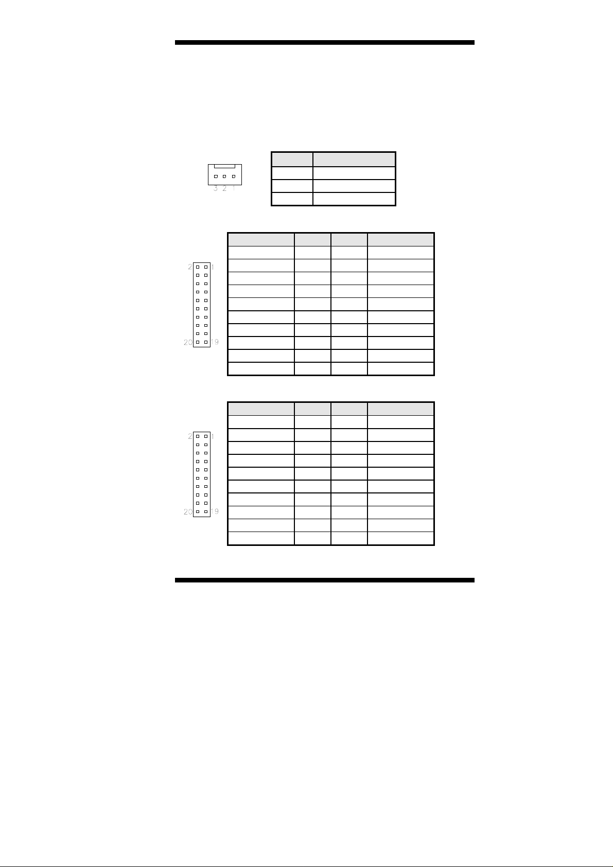
IBD185 Connectors Pin Definition
J1, J2 for I2C
Pin # Signal Name
1
2
3
J3 Supports 16-in GPIO
Signal Name Pin # Pin # Signal Name
3.3V 2 1 3.3V
DIN8 4 3 DIN0
DIN9 6 5 DIN1
DIN10 8 7 DIN2
DIN11 10 9 DIN3
DIN12 12 11 DIN4
DIN13 14 13 DIN5
DIN14 16 15 DIN6
DIN15 18 17 DIN7
Ground 20 19 Ground
J4 Supports 16-out GPIO
Signal Name Pin # Pin # Signal Name
3.3V 2 1 3.3V
OUTPUT24 4 3 OUTPUT16
OUTPUT25 6 5 OUTPUT17
OUTPUT26 8 7 OUTPUT18
OUTPUT27 10 9 OUTPUT19
OUTPUT28 12 11 OUTPUT20
OUTPUT29 14 13 OUTPUT21
OUTPUT30 16 15 OUTPUT22
OUTPUT31 18 17 OUTPUT23
Ground 20 19 Ground
SCL
SDA
GND
IBD185 User Guide 3
Page 4
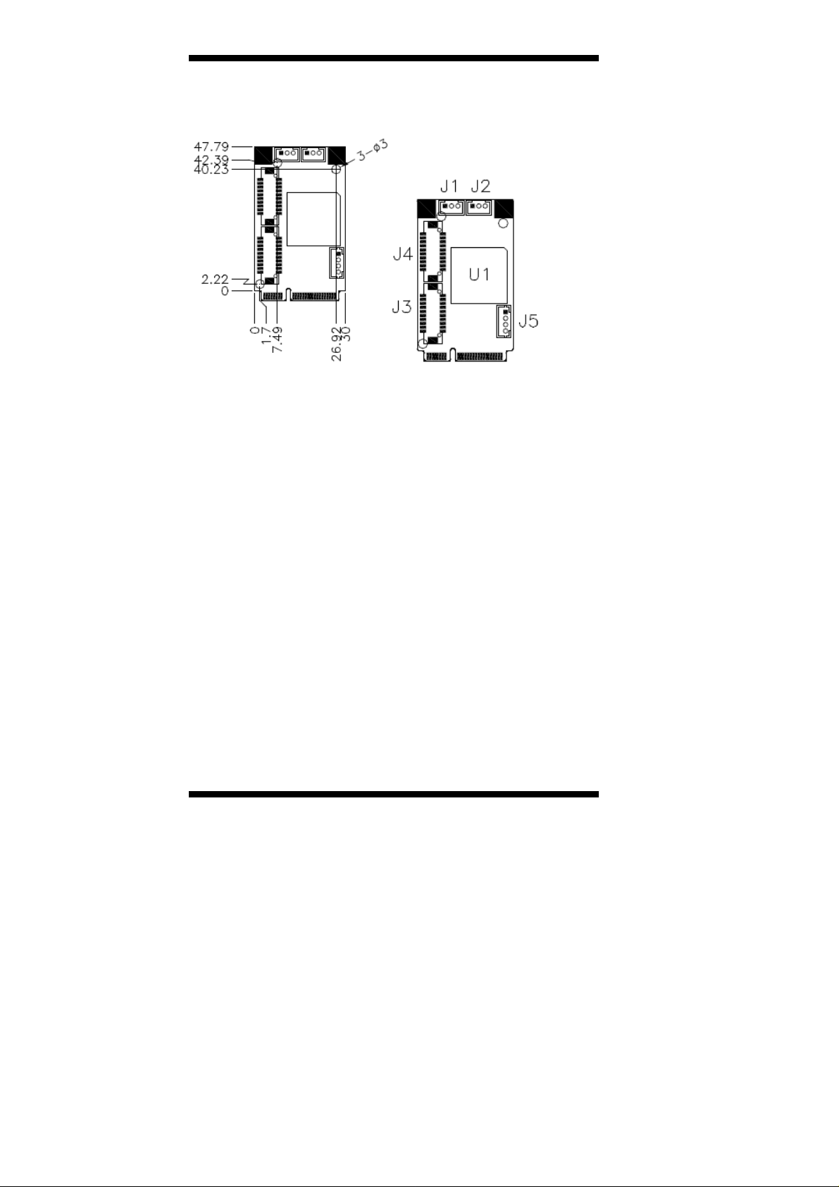
IBD185 Mechanical Drawing
4 IBD185 User Guide
Page 5
IBD185 Driver Installation
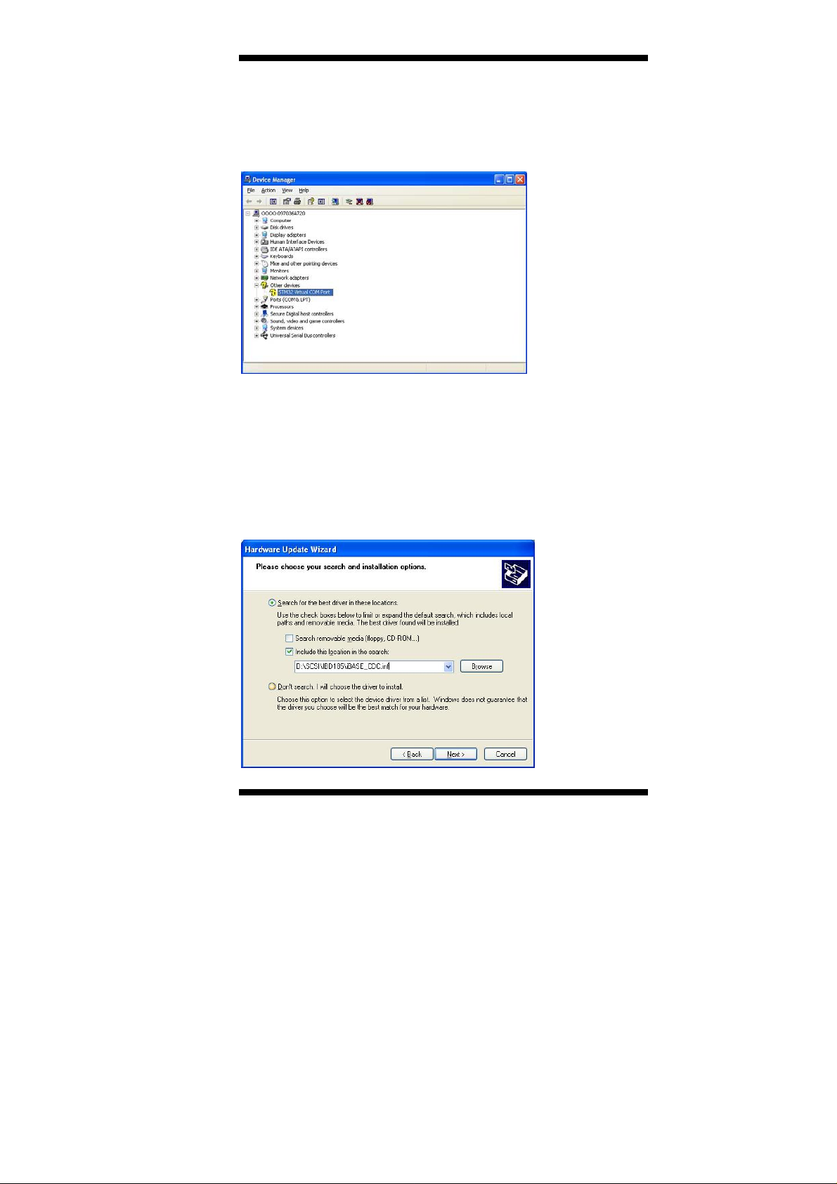
1. In the Windows OS, go to the Computer Management screen. In the
‘Other devices’ as shown, right click the “STM32 Virtual COM Port”
Properties.
2. In the STM32 Virtual COM Port Properties screen, click Update
Driver.
3. In the Hardware Update Wizard screen, select “No, not this time” and
click Next to continue.
4. Select “Install from a list or specific location (Advanced), and click
Next to continue.
5. To choose the “search” and “installation” options, click the checkbox
of “Include this location in the search”, and click Browse to find the
driver’s path in the CD provided or enter the path directly -
\SCSI\IBD185\iBASE_CDC.inf
IBD185 User Guide 5
Page 6

6. Click Continue Anyway.
7. Click Finish to close the wizard.
8. There are a total of two serial ports. Therefore, the Hardware Update
Wizard procedure has to be repeated for the rest of the serial ports
6 IBD185 User Guide
Page 7

IBD185 MCU Protocol Specification
1 Software Requirements
1.1 Description
MCU provides the following functionality:
1.1.1 GPIO configuration
Software can configure the functionality of GPIO pins on MCU.
MCU provides commands to configure the pin function as digital input
or digital output.
1.1.2 GPIO status
Software can control the output pin and get the status of input pin on
MCU.
MCU provides commands to control the output of pin which is
configured as an output pin or to read back the status of pin which is
configured as input pin.
1.1.3 I2C Bus interface
Software can perform I2C bus operation on MCU.
MCU provides command interface to control the I2C bus master on it.
1.2 Protocol
1.2.1 Signal transmission format
Bandwidth
Baud rate: 115200 bps.
Data Format
Parity: No Parity
1 start bit
8 data bits
1 stop bit
IBD185 User Guide 7
Page 8

1.2.2 Packet Format
Header Size Command Data CRC
2 bytes 1 byte 1 byte 0 – 64 bytes 2 bytes
Header
bytes indicate start of the packet.
Size
specifies number of bytes for data field.
CRC
verifies data integrity for header, size, command and data bytes.
Command
identifies action, which is required to be performed on the data.
1.2.3 CRC
Protocol uses 16-bit CCITT CRC to verify data integrity.
P(x) = X16+X12+X5+1.
unsigned calc_crc(unsigned char *data, unsigned n, unsigned start)
{
unsigned I, k, q, c, crcval;
crcval=start;
for (I=0; I<n; I++)
{
c=data(I) & 0xFF;
q=(crcval^c) & 0x0F;
crcval=(crcval>>4)^(q*0x1081);
q=(crcval^(c>>4)) & 0x0F;
crcval=(crcval>>4)^(q*0x1081);
}
return crcval;
}
1.2.4 Communications flow
Communication between PC and MCU utilizes Master-Slave
model, where PC is a master, and MCU is a slave.
Master sends requests to the slave, and slave has to reply to
them. Slave acts like a passive device and cannot send any
requests to the master.
8 IBD185 User Guide
Page 9

1.3 Command and Reply Codes
1.3.1 Summary
Code Value Description
GET_FIRMWARE_VERSION 0x80 Get MCU Firmware Version
GET_GPIO_CONFIG 0x8A Get GPIO configuration
SET_GPIO_CONFIG 0x8B Set GPIO configuration
GET_GPIO_STATUS 0x8C Get GPIO Status
SET_GPIO_STATUS 0x8D Set GPIO Status
I2C_API_COMMAND 0x8E I2C Bus Interface Command
<Note>The command 0xF0 ~ 0xFF is the reserved command for
instruction controller.
1.3.2 Get Mcu Firmware Version
Read version number of the MCU firmware
Request
Header Size Command Data CRC
0xFF
0xEE
0x00 GET_FIRMWARE_VERSION None
Reply
Header Size Command Data CRC
0xFF
0xEE
Size of
Version
structure
GET_FIRMWARE_VERSION Version
structure
Version Structure
Field Type Description
Major version byte Major version number
Minor version byte Minor version number
Build byte Build number
IBD185 User Guide 9
Page 10

1.3.3 Get GPIO Configuration
Read the GPIO pin configuration of the MCU
Request
Header Size Command Data CRC
0xFF
0xEE
The “GPIO Pin Index” of GPIO pin is count from 0.
Reply
Header Size Command Data CRC
0xFF
0xEE
Device reply a packet without “Data” field (“Size” is 0, none “Data”)
means fail. If the request performed successfully, device will reply a
packet with specific data structure.
The format is listed below:
GpioPinCfg Structure
Pin Index byte Pin Index
Pin Config Array of
Host can retrieve configurations of all GPIO pins by sending a request
packet with designating the field “Pin Index” in “GpioPinCfg” as 0xFF.
Device will reply a packet with all GPIO pins configurations in sequential
bytes array. The “Pin Config[]” bytes array are in order of the GPIO pin
index.
0x00 GET_GPIO_CONFIG GPIO Pin Index
Size of
GpioPinCfg
structure
Field Type Description
GET_GPIO_CONFIG GpioPinCfg
0x00 – 1st pin index
0x01 – 2nd pin index
……
0xFF – All of the pins
byte
Pin Configuration
0x00 – as a digital input pin
0x01 – as a digital output pin
The length of “Pin Config” is depends on the
number of “Pin Index”.
If the specific index is 0xFF means all of the
pins.
structure
10 IBD185 User Guide
Page 11

1.3.4 Set GPIO Configuration
Set up the GPIO pin configuration of the MCU
Request
Header Size Command Data CRC
0xFF 0xEE 0x00 SET_GPIO_CONFIG GPIO Pin Index
The “GPIO Pin Index” of GPIO pin is count from 0.
Reply
Header Size Command Data CRC
0xFF
0xEE
Size of
GpioPinCfg
structure
SET_GPIO_CONFIG GpioPinCfg
structure
Device reply a packet without “Data” field (“Size” is 0, none “Data”)
means fail. If the request performed successfully, device will reply a
packet with specific data structure.
The format is listed below:
GpioPinCfg Structure
Field Type Description
Pin Index byte Pin Index
Pin Config Array of
byte
0x00 – 1st pin index
0x01 – 2nd pin index
……
0xFF – All of the pins
Pin Configuration
0x00 – as a digital input pin
0x01 – as a digital output pin
Host can set configurations of all GPIO pins by sending a request packet
with designating the field “Pin Index” in “GpioPinCfg” as 0xFF.
Device will reply a packet with all GPIO pins configurations in sequential
bytes array. The “Pin Config[]” bytes array are in order of the GPIO pin
index.
IBD185 User Guide 11
Page 12

1.3.5 Get GPIO Status
Read the GPIO pin group status of the MCU
The status of a GPIO pin is represented by a byte of bitmap that groups
8 pins status in one register. This status bitmap is only valid for output
pins. Therefore the retrieved status bitmap should be masked with the
pin configurations of this group.
Request
Header Size Command Data CRC
0xFF
0xEE
The “GPIO Group Index” is count from 0 and can be calculated simply by
a formula: GPIO Group Index = (GPIO Pin Index/8)
Reply
Header Size Command Data CRC
0xFF
0xEE
Device reply a packet without “Data” field (“Size” is 0, none “Data”)
means fail. If the request performed successfully, device will reply a
packet with specific data structure. The format is listed below:
GpioGrpStatus Structure
Group Index byte Group Index
Group Status Array of
Host can retrieve status of all GPIO pins by sending a request packet with
designating the field “Group Index” in “GpioGrpStatus” as 0xFF.
Device will reply a packet with all GPIO pins status in sequential bytes
array. The “Group Status[]” bytes array are in order of the GPIO group
index. Besides, the bit sequence in a “Group Status” byte is mapping to
the order of pin index in the same GPIO group.
0x00 GET_GPIO_STATUS GPIO Group Index
Size of
GpioGrpStatus
structure
Field Type Description
byte
GET_GPIO_STATUS GpioGrpStatus
structure
0x00 – 1st group index
0x01 – 2nd group index
……
0xFF – All of the groups
Status bitmap of grouped pins
bit 0 .. bit 7 for each of the pin signal and the
bitmapping define is
listed below :
0[bit] – signal level Low (logic 0)
1[bit] – signal level High (logic 1)
12 IBD185 User Guide
Page 13

1.3.6 Set GPIO Status
Set up the GPIO pin group status of the MCU
The status of a GPIO pin is represented by a byte of bitmap that groups
8 pins status in one register. This status bitmap is only valid for output
pins. Please make the settings of status bitmap according to the pin
configurations of this group.
Request
Header Size Command Data CRC
0xFF
0xEE
The “GPIO Group Index” is count from 0 and can be calculated simply by
a formula: GPIO Group Index = (GPIO Pin Index/8)
Reply
Header Size Command Data CRC
0xFF
0xEE
Device reply a packet without “Data” field (“Size” is 0, none “Data”)
means fail. If the request performed successfully, device will reply a
packet with specific data structure. The format is listed below:
GpioGrpStatus Structure
Group Index byte Group Index
Group Status Array of
Host can set status of all GPIO output pins by sending a request packet
with designating the field “Group Index” in “GpioGrpStatus” as 0xFF.
Device will reply a packet with all GPIO pins status in sequential bytes
array. The “Group Status[]” bytes array are in order of the GPIO group
index. Besides, the bit sequence in a “Group Status” byte is mapping to
the order of pin index in the same GPIO group.
Size of
GpioGrpStatus
structure
SET_GPIO_STATUS GPIO Group
Index
Size of
GpioGrpStatus
structure
Field Type Description
byte
SET_GPIO_STATUS GpioGrpStatus
structure
0x00 – 1st group index
0x01 – 2nd group index
……
0xFF – All of the groups
Status bitmap of grouped pins
bit 0 .. bit 7 for each of the pin signal and the
bitmapping define is
listed below :
0[bit] – signal level Low (logic 0)
1[bit] – signal level High (logic 1)
IBD185 User Guide 13
Page 14

1.3.7 I2C Bus Interface Sub Command Set
This command set is a subset of the IB protocol command.
It provides an interface for HOST to control the I2C bus master on
DEVICE side.
The sub command set is constructed by a specific command ID
(I2C_API_COMMAND) in “Command” field of packet, and the payloads
are embedded in “Data” field.
Header Size Command Data CRC
2 bytes 1 byte 1 byte 0 – 64 bytes 2 bytes
Sub Command
Length
1 byte 1 byte 0 – 32 bytes
The supported command of I2C bus interface command set list below:
Code Symbol Description
0x01 I2CAPI_BUS_INIT Initial the specific I2C bus master
0x02 --- reserved
0x03 I2CAPI_BUS_ENABLE Enable/Disable the specific I2C bus
0x04 I2CAPI_DEV_STATUS Detect the slave status on the
0x05 I2CAPI_DEV_READ Perform I2C device read operation
0x06 I2CAPI_DEV_WRITE Perform I2C device write operation
0x07 I2CAPI_BUS_RESET Reset the specific I2C bus
0x08 --- reserved
Here is a simple illustration of the interface functions in pseudo code.
I2C_Bus_Init(BusID,Speed);
I2C_Bus_Enable(BusID,Enabled);
I2C_Device_Detect(BusID,SlvAddr);
I2C_Device_Read(BusID,SlvAddr,CmdLen,CmdCode[8],Flag,DatLen,
DatBuff[32]);
I2C_Device_Write(BusID,SlvAddr,CmdLen,CmdCode[8],Flag,DatLen,
DatBuff[32]);
I2C_Bus_Reset(BusID,Flag);
Sub Command
Code
Sub Command Set
Sub Command
Data
specific I2C bus.
14 IBD185 User Guide
Page 15

I2C Bus Initialize
Initialize the I2C bus master on MCU.
Start up an I2C bus with specific Bus ID and Speed.
The Bus ID can be 1 or 2.
Bus ID is 1 means the I2C1 on MCU, and so on.
The Speed can be 0, 1, 2.
Speed=0 means de-initialize the I2C Bus.
Speed=1 means initialize the specific I2C Bus in 400Kbps.
Speed=2 means initialize the specific I2C Bus in 100Kbps (default).
Sub Command Request
Sub
Command
Length
size of the
I2cApiBusInit
structure
Sub Command
Code
I2CAPI_BUS_INIT I2cApiBusInit structure
Sub Command
Data
Sub Command Reply
Sub
Command
Length
size of the
I2cApiBusInit
structure +1
Sub Command
Code
I2CAPI_BUS_INIT I2cApiBusInit structure followed by
one byte I2cApiResult
Sub Command
Data
The reply packet contains the parameters that device received and
followed by one byte of result.
I2cApiResult = 0 means the execution result is fail.
I2cApiBusInit Structure
Field Type Description
Bus ID byte Designate which I2C bus on MCU
Bus Speed byte I2C bus speed selection
1 – 1st I2C bus master
2 – 2nd I2C bus master
0: De-Initialize the specific I2C bus
1: 400Kbps
2: 100Kbps (default)
IBD185 User Guide 15
Page 16

I2C Bus Enable
Enable/Disable the specific I2C bus master on MCU.
Sub Command Request
Sub Command
Length
size of the
I2cApiBusEnabled
structure
Sub Command
Code
I2CAPI_BUS_ENABLE I2cApiBusEnabled structure
Sub Command
Data
Sub Command Reply
Sub Command
Length
size of the
I2cApiBusEnabled
structure +1
Sub Command
Code
I2CAPI_BUS_ENABLE I2cApiBusEnabled structure
Sub Command
Data
followed by one byte
I2cApiResult
The reply packet contains the parameters that device received and
followed by one byte of result.
I2cApiResult = 0 means the execution result is fail.
I2cApiBusEnabled Structure
Field Type Description
Bus ID byte Designate which I2C bus on MCU
Bus Enabled byte I2C bus enabled
1 – 1st I2C bus master
2 – 2nd I2C bus master
0: Disable
1: Enable
16 IBD185 User Guide
Page 17
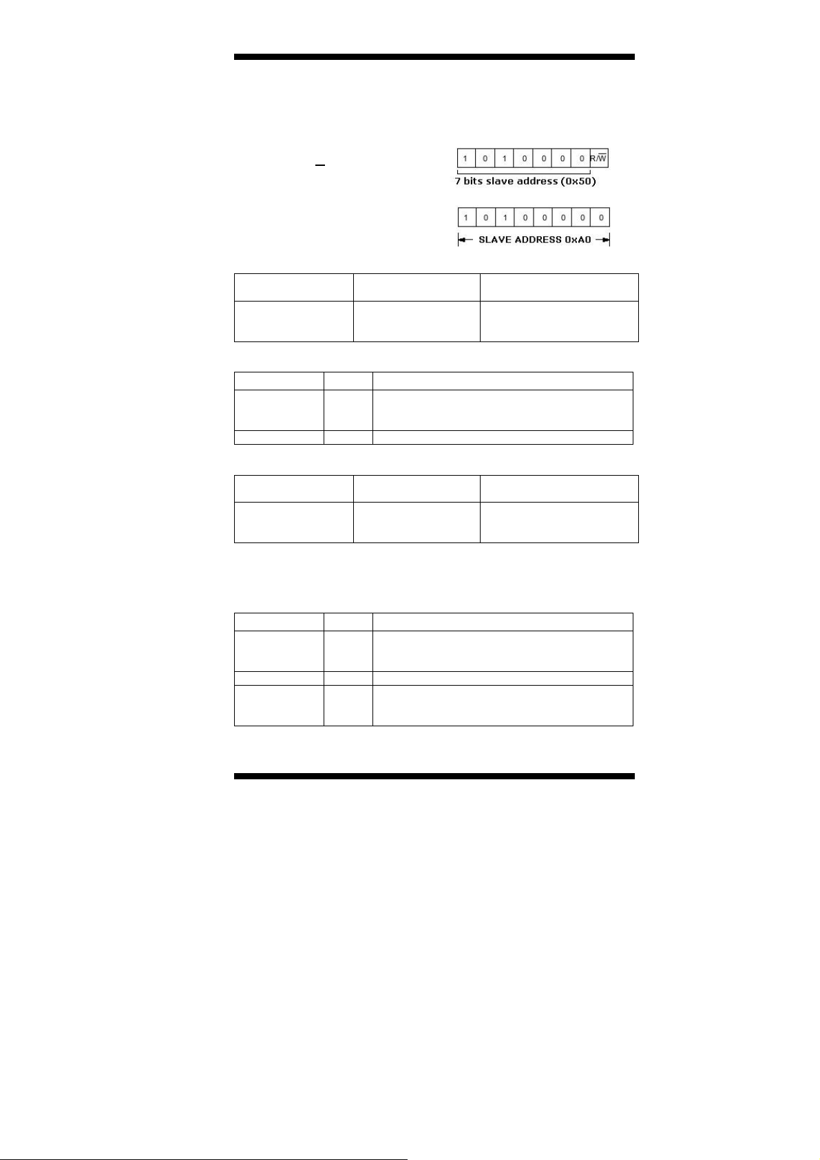
I2C Device Status
Try to detect the slave device status on the specific I2C bus.
The slave address should be
left shift one bit to skip the position
of the LSB (R/W bit).
For Example:
Stuff the slave address with 0xA0
to designate the slave device which
7 bits slave address is 0x50.
Sub Command Request
Sub Command
Length
size of the
I2cApiDevStatus_T
structure
I2cApiDevStatus_T Structure
Field Type Description
Bus ID byte Designate which I2C bus on MCU
Slv Addr byte 7bits I2C slave address
Sub Command Reply
Sub Command
Length
size of the
I2cApiDevStatus_R
structure+1
The reply packet contains the I2cApiBusStatus_R structure and followed
by one byte of result.
I2cApiResult = 0 means the execution result is fail.
I2cApiDevStatus_R Structure
Field Type Description
Bus ID byte Designate which I2C bus on MCU
Slv Addr byte I2C slave address
Slv Status
byte Status of the specific slave address
Sub Command
Code
I2CAPI_DEV_STATUS I2cApiDevStatus_T
1 – 1st I2C bus master
2 – 2nd I2C bus master
Sub Command
Code
I2CAPI_DEV_STATUS I2cApiDevStatus_R
1 – 1st I2C bus master
2 – 2nd I2C bus master
0:Not ready (Busy/Fail)
1:Ready
Sub Command
Data
structure
Sub Command
Data
structure followed by
one byte I2cApiResult
IBD185 User Guide 17
Page 18

I2C Device Read/Write
The two interfaces are providing generic command format for I2C bus
read/write operation.
The generic command format of an I2C operation can be shown below:
BudID SlvAdd CmdLen CmdCode Flag DatLen DatBuff
Bud ID
1:I2C1
2:I2C2
Limitation:
The max length of command code limits in 8 bytes.
The max length of data byte limits in 32 bytes.
The generic command can be varied to several types of I2C read/write
operations. Such as Byte Write/Byte Read, Word Write/Word Read,
Sequential Write/Sequential Read, and Block Write/Block Read.
Stuff the command interface with proper arguments to perform different
kinds of I2C read/write depends on your needs.
Please refer to the user’s manual of your I2C slave device to transmit the
I2C command in correct format.
(7bits
SADD
<<1)
Length of
CmdCode
Command
code
0:Normal
1:Block
Length of
DatBuff
Data
bytes
18 IBD185 User Guide
Page 19

I2C Device Read
Perform an I2C bus read operation.
Sub Command Request
Sub Command
Length
size of the
I2cApiDevRead_T
structure
I2cApiDevRead_T Structure
Field Type Description
Bus ID byte Designate which I2C bus on MCU
Slv Addr byte I2C slave address
Cmd Len byte Length of the following command code
Cmd Code Array of byte command code
Flag byte operation flag
Dat Len byte Number of the data bytes you want to read.
Sub Command
Code
I2CAPI_DEV_READ I2cApiDevRead_T structure
1 – 1st I2C bus master
2 – 2nd I2C bus master
0x00: Normal operation
0x01: Block operation
Sub Command
Data
IBD185 User Guide 19
Page 20

Sub Command Reply
Sub Command
Length
size of the
I2cApiDevRead_R
structure
The reply packet contains the I2cApiDevRead_R structure.
The I2cApiDevRead_R structure returns the device received significant
arguments and followed by one byte result.
If the read operation has performed successfully, the result would be
equal to the value of “Dat Len” and the retrieved sequential reading
data bytes should concatenated to the result byte in the rear of packet,
otherwise the read operation has error, the returned packet would be
without reading data bytes.
Sub Command
Code
I2CAPI_DEV_READ I2cApiDevRead_R structure
Sub Command
Data
It contains the read back
data.
I2cApiDevRead_R Structure
Field Type Description
Bus ID byte Designate which I2C bus on MCU
Slv Addr byte I2C slave address
Cmd Len byte Length of the command code
Flag byte operation flag
Dat Len byte Length of the data byte
Result byte Operation result
Dat Buff Array of byte Data bytes
1 – 1st I2C bus master
2 – 2nd I2C bus master
0x00: Normal operation
0x01: Block operation
Result >=0 and Result <=32 : Done
Result >32 : Error
The read operation is Success if the “Result”
is equal to the number of bytes you want to
read.
The data bytes to read in sequence.
20 IBD185 User Guide
Page 21

I2C Device Write
Perform an I2C bus write operation.
Sub Command Request
Sub Command
Length
size of the
I2cApiDevWrite_T
structure
I2cApiDevWrite_T Structure
Field Type Description
Bus ID byte Designate which I2C bus on MCU
Slv Addr byte I2C slave address
Cmd Len byte Length of the following command code
Cmd Code Array of byte command code
Flag byte operation flag
Dat Len byte Number of the data bytes you want to write.
Dat Buff Array of byte Data bytes
Sub Command
Code
I2CAPI_DEV_WRITE I2cApiDevWrite_T structure
1 – 1st I2C bus master
2 – 2nd I2C bus master
0x00: Normal operation
0x01: Block operation
The data bytes to write in sequence.
Sub Command
Data
IBD185 User Guide 21
Page 22

Sub Command Reply
Sub Command
Length
size of the
I2cApiDevWrite_R
structure
The reply packet contains the I2cApiDevWrite_R structure.
Sub Command
Code
I2CAPI_DEV_WRITE I2cApiDevWrite_R structure
Sub Command
Data
The I2cApiDevWrite_R structure returns the device received significant
arguments and followed by one byte result.
I2cApiDevWrite_R Structure
Field Type Description
Bus ID byte Designate which I2C bus on MCU
Slv Addr byte I2C slave address
Cmd Len byte Length of the command code
Flag byte operation flag
Dat Len byte Length of the data byte
Result byte Operation result
1 – 1st I2C bus master
2 – 2nd I2C bus master
0x00: Normal operation
0x01: Block operation
Result >=0 and Result <=32 : Done
Result >32 : Error
The read operation is Success if the “Result”
is equal to the number of bytes you want to
write.
22 IBD185 User Guide
Page 23

I2C Bus Reset
Reset the specific I2C bus master on MCU.
Sub Command Request
Sub Command
Length
size of the
I2cApiBusReset
structure
Sub Command
Code
I2CAPI_BUS_RESET I2cApiBusReset structure
Sub Command
Data
Sub Command Reply
Sub Command
Length
size of the
I2cApiBusReset
structure +1
Sub Command
Code
I2CAPI_BUS_RESET I2cApiBusReset structure
Sub Command
Data
followed by one byte
I2cApiResult
The reply packet contains the parameters that device received and
followed by one byte of result.
I2cApiResult = 0 means the execution result is fail.
I2cApiBusReset Structure
Field Type Description
Bus ID byte Designate which I2C bus on MCU
Flag byte Flag for reset I2C bus
1 – 1st I2C bus master
2 – 2nd I2C bus master
0: Re-Config I2C bus (default)
1: Reset I2C bus (reserved)
IBD185 User Guide 23
Page 24

APPENDIX
A protocol instruction example for I2C read/write operation:
The I2C device (24C02 EEPROM) is connected to the I2C1 Bus on MCU.
(7bits SlaveAddress: 0x50, 8 bytes per page)
Page Write from address 0x00 on 24C02
REQUEST PACKET:
Header Size Command
0xFF,
0xEE
Sub
Cmd
Len
14 0x06
REPLY PACKET:
Header Size Command
0xFF,
0xEE
Sub
Cmd
Len
6 0x06
16 0x8E
Data CRC
Sub
Cmd
Code
Sub Cmd Data
BudID SlvAdd CmdLen CmdCode
0x01
(I2C1)
0xA0
(0x50
1 0x00
<<1)
Flag DatLen DatBuff
0x00 8 0x00,0x01,0x02,0x03,
0x04,0x05,0x06,0x07
8 0x8E
Data CRC
Sub
Cmd
Code
Sub Cmd Data
BudID SlvAdd CmdLen
0x01
(I2C1)
0xA0
(0x50
1
<<1)
Flag DatLen Result
0x00 8 8
(Result==DatLen
means success)
0x8E,
0x61
(writing
from 0x00)
0x7E,
0x38
24 IBD185 User Guide
Page 25

Read 8 bytes from address 0x00 on 24C02
REQUEST PACKET:
Header Size Command
0xFF,
8 0x8E
0xEE
Data CRC
Sub
Cmd
Len
Sub
Cmd
Code
Sub Cmd Data
6 0x05
BudID SlvAdd CmdLen CmdCode
0x01
(I2C1)
0xA0
(0x50
<<1)
1 0x00
(reading
from 0x00)
Flag DatLen
0 8
REPLY PACKET:
Header Size Command
0xFF,
16 0x8E
0xEE
Data CRC
Sub
Cmd
Len
Sub
Cmd
Code
Sub Cmd Data
14 0x05
BudID SlvAdd CmdLen
0x01
(I2C1)
0xA0
(0x50
1
<<1)
Flag DatLen Result DatBuff
0 8 8
(Result==
DatLen
means
success)
0x00,0x01,
0x02,0x03,
0x04,0x05,
0x06,0x07
0xD0,
0x5E
0xD9,
0xD0
IBD185 User Guide 25
 Loading...