

Page 1

FWA9300 Series
Network Appliance
User′s Manual
Version: 1.0
Page 2

History
Revision Date Description Remark
0.1 Oct.13.2008 Initial No IPMI & IIO
1.0 Nov.26.2008 Addition IPMI manual
Page 3

Table of Contents
Chapter 1 Introduction....................................................................................................... 1
Chapter 2 System Specification ........................................................................................ 2
Chapter 3 Hardware Configuration .................................................................................. 3
Chapter 4 System Architecture ......................................................................................... 5
Chapter 5 IPMI manual...................................................................................................... 6
Page 4

Foreword
To prevent damage to the system board, please handle it with care and follow the measures below, which
are generally sufficient to protect your equipment from static electricity discharge:
When handling the board, use a grounded wrist strap designed for static discharge elimination grounded to
a metal object before removing the board from the antistatic bag. Handle the board by its edges only; do
not touch its components, peripheral chips, memory modules or gold contacts.
When handling processor chips or memory modules, avoid touching their pins or gold edge fingers. Return
the Network Appliance system board and peripherals back into the antistatic bag when not in use or not
installed in the chassis.
Some circuitry on the system board can continue to operate even though the power is switched off. Under
no circumstances should the Lithium battery cell used to power the real-time clock be allowed to be shorted.
The battery cell may heat up under these conditions and present a burn hazard.
WARNING!
1. "CAUTION: DANGER OF EXPLOSION IF BATTERY IS INCORRECTLY REPLACED.
REPLACE ONLY WITH SAME OR EQUIVALENT TYPE RECOMMENDED BY THE
MANUFACTURER. DISCARD USED BATTERIES ACCORDING TO THE
MANUFACTURER’S INSTRUCTIONS"
2. This guide is for technically qualified personnel who have experience installing and configuring system
boards. Disconnect the system board power supply from its power source before you
connect/disconnect cables or install/remove any system board components. Failure to do this can result
in personnel injury or equipment damage.
3. Avoid short-circuiting the lithium battery; this can cause it to superheat and cause burns if touched.
4. Do not operate the processor without a thermal solution. Damage to the processor can occur in
seconds.
5. Do not block air vents at least minimum 1/2-inch clearance required.
Page 5

Chapter 1 Introduction
The FWA9300 series was specifically designed for the network security & management market.
Network Security Applications:
• Firewall
• Virtual Private Network
• Proxy Server
• Caching Server
Network Management Applications:
• Load balancing
• Quality of Service
• Remote Access Service
The FWA network appliance product line covers the spectrum from offering
platforms designed for :
• SOHO
• SMB
• Enterprise
Each product is designed to address the distinctive requirements of its
respective market segment from cost effective entry-level solutions to
high throughput and performance-bound systems for the Enterprise level.
Page 6

Chapter 2 System Specification
pin DDR2 sockets, supporting REG/ECC DDR2 533 / 667 up to 48GB
PCIe x16 x1 for Expansion Riser Card , PCIe x16 can support 4 devices
Product Name FWA9300
Form Factor 19” 2U rack mount
CPU Socket LGA771 socket X 2
CPU Type Quad-Core Intel® Xeon® processor 5000Δ series
Dual-Core Intel® Xeon® processor 5000Δ series
CPU FSB 1066 / 1333 MHz FSB
Chipset Intel® San Clemente(5100) MCH + ICH9R
BIOS AMI BIOS---MS SLP 2.0,
Memory
LAN Onboard dual port Intel® 82575 gigabit LAN
VGA+IPMI AST2050 supports 2D Graphics and IPMI 2.0
USB 4 ports USB2.0
Serial ATA 4 ports SATAII, support raid 0,1,5,10
Swappable HDD Tray 2 swappable trays, support SATA & SAS
LPC I/O 2 com-ports, Winbond W83627DHG supports COM1 (RS232) for Console with
Edge Connectors Front Panel: RJ45 connector for LAN1~4
On Board Headers /
Connectors
Golden Finger
Watchdog Timer Yes (256 segments, 0, 1, 2…255 sec/min)
RoHS Compliant Yes
Board Size W:155mm * L:425mm
6x 240memory
Onboard dual port Intel® 82571 gigabit LAN
D-Sub9 connector
Dual USB stack connector x1 for USB 0, 1
Rear Panel: DB-15 Connector for VGA x1 (option)
USB connector x1 (option)
Standard SATA (7-pin shrouded vertical) connector x 4
4-pin PWM FAN pin-header x 6 for CPU & system fans by fan board
2x 8 pins pin-header x1 for VGA—Rear Panel
4x2 pins pin-header x1 for USB 2, 3----Rear Panel
5x2 pins box-header x1 for COM2----IIO LCM module
2 x 5 pins pin-header for PS/2 Keyboard & Mouse
ATX Power Connector (ATX20P+ EPS8P)
One LPC debug port for 7-seg 80 port dongle
(customize backplane)
Page 7
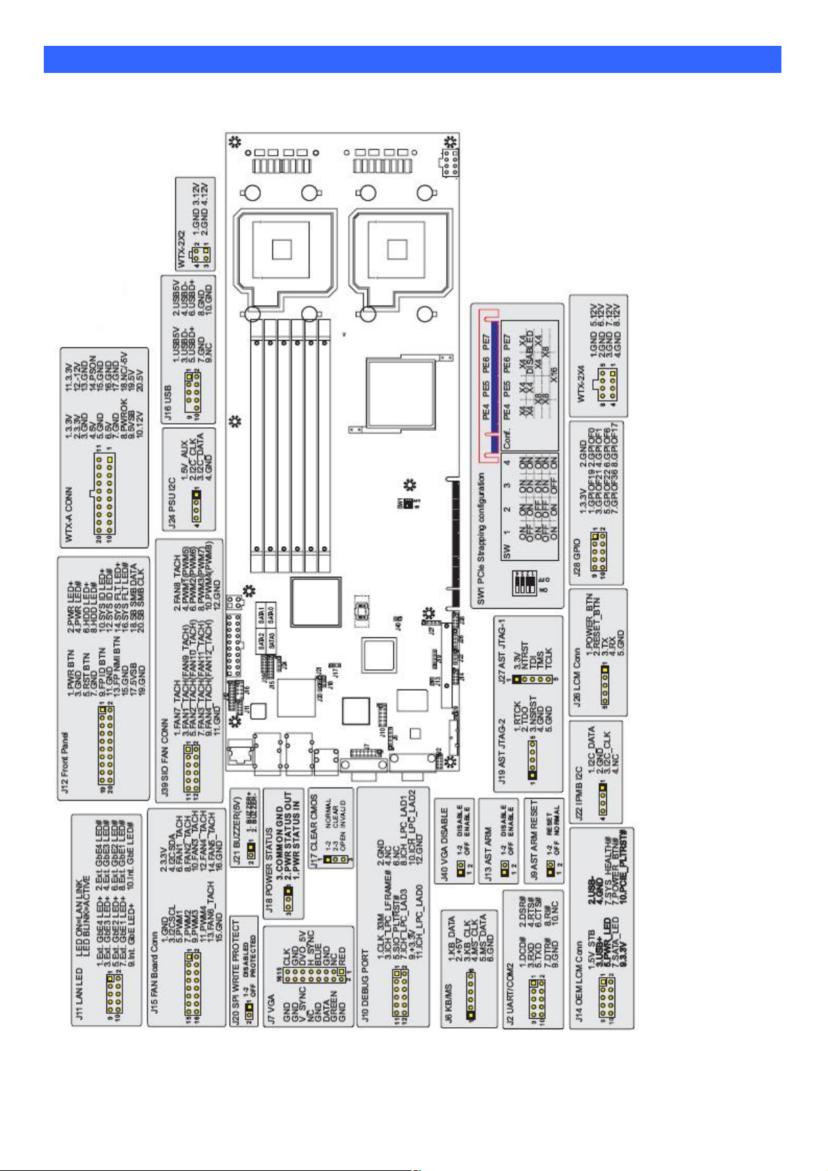
Chapter 3 Hardware Configuration
CPU board layout & Jumper Setting
Page 8
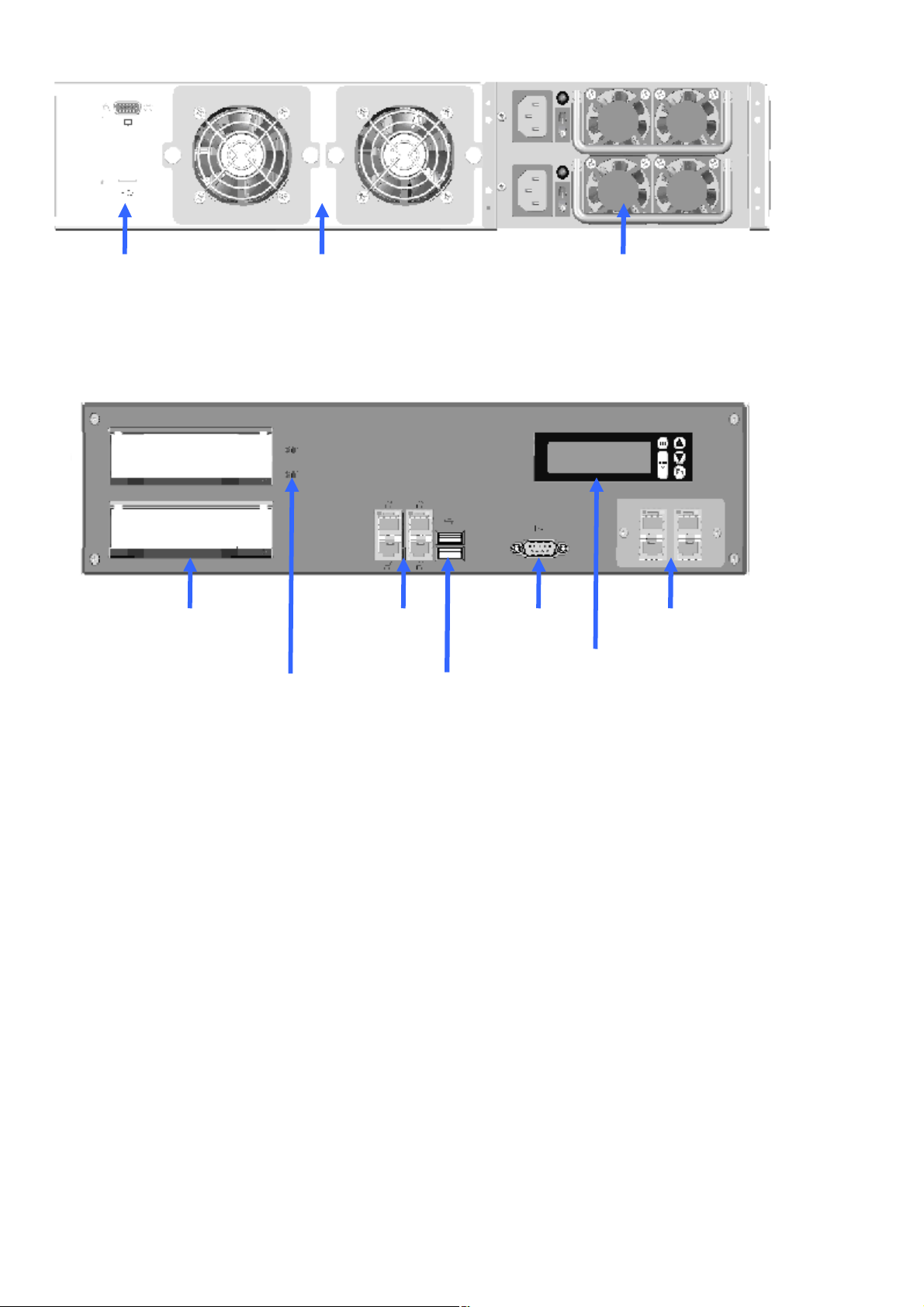
Rear Panel Features
6CM
2 1.
VGA (option)
2U 1+1 500W
(
SAS or SATA
)
IIO
1
2. USB (Option)
Front Panel Features
Swappable HDD Tray
Swappable
system Fan
4ports GbE
(left button
port is IPMI)
Redundant PSU
Comport
(console)
LAN module
(customize)
HDD status LED
2ports USB2.0
Page 9
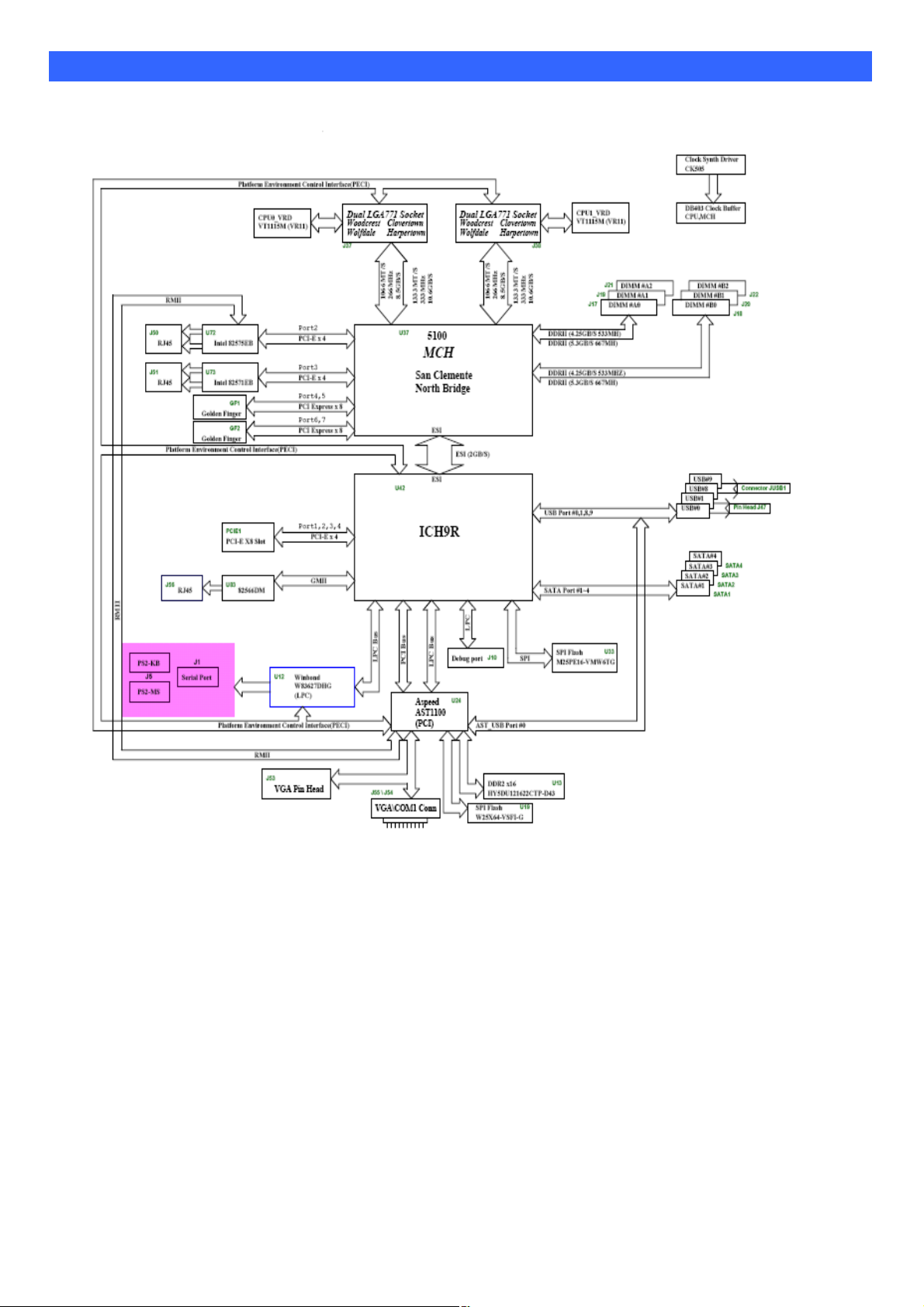
Chapter 4 System Architecture
The following block diagram illustrates a basic design reference of FWA9300, a highly integrated system
solution.
Page 10

Chapter 5 IPMI Manual
Limited Warranty
The buyer agrees that if this product proves to be defective, American Megatrends is only obligated to repair or replace
this product at American Megatrends’ discretion according to the terms and conditions of the warranty
registration card that accompanies this product. American Megatrends shall not be liable in tort or contract for any
loss or damage, direct, incidental or consequential resulting from the use of this product. Please see the Warranty
Registration Card shipped with this product for full warranty details.
Using Your ASTER
ASTER GUI Overview
The ASTER has a user-friendly Graphics User Interface (GUI) called the ASTER GUI. It is
designed to be easy to use. It has a low learning curve because it uses a standard Internet
browser. You can expect to be up and running in less than five minutes.
This chapter allows you to become familiar with the ASTER GUI’s various functions.
Each function is described in detail.
Default User Name and Password
When you first try to access your ASTER, you will be prompted to enter a user name and
password. The default user name and password are as follows:
Note:
Note:
Field
User Name
Password
The default user name and password are in lower-case characters.
When you log in using the root user name and password, you have full
administrative powers. It is advised that once you log in, you change the root
password.
Default
root
superuser
Page 11

ASTER GUI Explained
After you successfully log into your ASTER, you are greeted with the ASTER GUI.
Menu Bar
Function Title
Section
Information
Function
List
Page 12

General Information
1. General Information: It shows the firmware of ASTER information.
2. List FRU: It goes through the I2C bus to detect the FRU data of motherboard BMC.
Page 13

Server Health
1. Sensor Readings: It reads the sensor information of system. You can click the “Refresh” to
re-read the sensor state. And you can click “Show Thresholds” to show the thresholds of
every sensors.
2. Event Log: It records the event when sensor has abnormal state.
Page 14

Configuration
1.Network: Show the ASTER IP address information. You can set DHCP or STATIC IP
then click “Save”.
Page 15

2.Users: You can control user who can login ASTER and accessing privileges.
3. Alerts: Set the IP address who wants to get the alert message when system is abnormal.
Page 16

4.Mouse mode: There are two types for control mouse.
5. LDAP: It can download user list of LDAP server then create ASTER user account from
this list directly.
Page 17

SSL Certificate
You can load your SSL file for encryption.
Page 18

Remote Control
This menu item allows you to start a Remote Console session with the host system.
Redirection
The most powerful feature of your ASTER is the ability to redirect the host system’s
console. To redirect the host system’s console is the ability to manage your host
system as if it were physically in front of you, but not.
Setting up Internet Explorer
You must first setup your Internet browser before you can redirect the host
system’s console.
Step Description
1
Open Internet Options. To get there, open your Internet Explorer browser,
left click Tools and then Internet Options.
2
The Internet Options window opens. Left click the Settings button.
Page 19

Redirection,
Setting up Internet Explorer,
Step Description
3
The Settings window opens. Left click the Every visit to the page button or
Automatically button. Left click the OK button to apply the change and to go
back to the Internet Options window.
Note: Other settings can cause old data to be displayed when performing operations on the
ASTER.
Next, you must setup Internet Explorer to allow the downloading of Signed ActiveX
4
controls and also allow it to run Signed ActiveX controls. To do this, left click the
Security tab and then the Custom Level button.
Note: In Microsoft Windows 2003 server operating systems, the default security setting is
High, and this disables many items (besides the Active X ones mentioned in this
document) that are necessary to even access the ASTER GUI. The security settings
for a Microsoft Windows 2003 server operating system remote client must be on
Medium or Low.
Page 20

Redirection,
Setting up Internet Explorer,
Step Description
5 The Security Settings window opens. Left click the Enable button under the
Download signed ActiveXcontrols section.
6
Scroll down and left click the Enable button under the Run ActiveX controls
and plug-ins section. Left click the OK button.
Page 21

Redirection,
Setting up Internet Explorer,
Step Description
7
You are prompted with a Warning window. Left click the Yes button to accept the
changes to the Internet zone and to go back to the Internet Options window.
8
Left click the Apply button and then the OK button to make the changes.
Note: You must restart Internet Explorer before the changes take effect.
Note: Remote Console cannot run with any other security settings in Internet Explorer.
Page 22

Redirection,
1. Launch Redirection: It can do the console redirection by ActiveX mode and Java mode.
ActiveX mode is for user of windows OS. Java mode is for user of Linux OS.
Click “Active console”, it shows the console redirection screen. And click “Mouse” item to
Sync Cursor.
Page 23

Redirection,
Console Redirection Window
Dropdown
Menu Item
Console
Redirection
This dropdown menu contains the following dropdown menu items:
Start Redirection
Stop Redirection
Restart
Full Screen
Exit
Description
This menu item can be used to begin Console Redirection.
This menu item can be used to halt Console Redirection.
This menu item can be used to stop Console Redirection and
then start Console Redirection again.
This menu item can be used to view the Console Redirection
In Full Screen mode.
Note: Set your client system’s screen resolution to 1024 x768
so that you can view the host system in true full screen.
Exit console redirection.
Page 24

Redirection,
Console Redirection Window,
Dropdown
Menu Item
Keyboard
This dropdown menu contains the following dropdown menu items:
Hold Right CTRL Key
Hold Right ALT Key
Hold Left CTRL Key
Hold Left ALT Key
Left Windows Key
Right Windows Key
ALT+CTRL+DEL
Full Keyboard
Description
This menu item can be used to act as the right-side <CTRL>
key when in Console Redirection.
This menu item can be used to act as the right-side
<ALT> key when in Console Redirection.
This menu item can be used to act as the left-side
<CTRL> key when in Console Redirection.
This menu item can be used to act as the left-side
<ALT> key when in Console Redirection.
This menu item can be used to access the left-side
<WINDOWS> key during a Console Redirection session. The
following actions can be performed:
3. Hold Down
4. Press and Release
This menu item can be used to access the right-side
<WINDOWS> key during a Console Redirection session. The
following actions can be performed:
5. Hold Down
6. Press and Release
This menu item can be used to act as if you depressed the
<CTRL>, <ALT> and <DEL> keys down simultaneously on
the host system that you are redirecting.
The client keyboard is full control to host keyboard
including function key.
Cont’d
Page 25

Redirection,
Console Redirection Window,
Dropdown
Menu Item
Mouse
Video Engine
Configuration
It can be regulated the video performance for network
bandwidth.
Description
Sync Cursor for remote control mouse.
Page 26

Dropdown
Menu Item
Device
Help
Description
Virtual device for remote control.
CDROM redirection: This menu item can be used to start or stop the
redirection of the CD-ROM drive.
Floppy redirection: This menu item can be used to start or stop the
redirection of the floppy drive.
This dropdown menu item contains the About Remote Console
Application Control menu item that allows you to view copyright information.
Page 27

2. Server Power Control: This menu item allows you to power on, power off, power cycle,
and reset the host system. You can through IPMB bus or power
control feature connector to do command.
Maintenance
This menu item allows you to update your ASTER’s firmware.
 Loading...