

Page 1

FWA8206 Series
Network Appliance
User′s Manual
Version: 1.0
Page 2

Table of Contents
Chapter 1 Introduction ................................................................................................................... 3
Chapter 2 System Specification ................................................................................................... 4
Chapter 3 Hardware Configuration .............................................................................................. 5
Chapter 4 Console Mode Information ......................................................................................... 7
Chapter 5 Opening the chassis .................................................................................................... 9
Chapter 6 Removing and Installing DIMM ............................................................................... 10
Chapter 7 Removing and Installing CompactFlash Card ..................................................... 11
Chapter 8 Removing and Installing the Battery ..................................................................... 12
Chapter 9 Installing the 3.5” HDD .............................................................................................. 13
Chapter 10 Installing the 2.5” HDD .............................................................................................. 14
Chapter 11 BIOS Information ........................................................................................................ 15
Chapter 12 Bypass Information .................................................................................................... 28
Chapter 13 Factory Default Information ..................................................................................... 31
Chapter 14 GPO LED Information ................................................................................................ 33
Chapter 15 System Architecture .................................................................................................. 36
Page 3

Foreword
To prevent damage to the system board, please handle it with care and follow the measures below,
which are generally sufficient to protect your equipment from static electricity discharge:
When handling the board, use a grounded wrist strap designed for static discharge elimination grounded
to a metal object before removing the board from the antistatic bag. Handl e the board by its edges only;
do not touch its components, peripheral chips, memory modules or gold contacts.
When handling processor chips or memory modules, avoid touching their pins or gold edge fingers.
Return the Network Appliance system board and peripherals back into the antistatic bag when no t in use
or not installed in the chassis.
Some circuitry on the system board can continue to operate even though the power is switched off.
Under no circumstances should the Lithium battery cell used to power the real-time clock be allowed to
be shorted. The battery cell may heat up under these conditions and present a burn hazard.
WARNING!
1. "CAUTION: DANGER OF EXPLOSION IF BATTERY IS INCORRECTLY REPLACED.
REPLACE ONLY WITH SAME OR EQUIVALENT TYPE RECOMMENDED BY THE
MANUFACTURER. DISCARD USED BATTERIES ACCORDING TO THE
MANUFACTURER’S INSTRUCTIONS"
2. This guide is for technically qualified personnel who have experience installing and configuring
system boards. Disconnect the system board power supply from its power source before you
connect/disconnect cables or install/remove any system board components . Failure to do this can
result in personnel injury or equipment damage.
3. Avoid short-circuiting the lithium battery; this can cause it to superheat and cause burns if touched.
4. Do not operate the processor without a thermal solution. Damage to the processor can occur in
seconds.
5. Do not block air vents at least minimum 1/2-inch clearance required.
FWA8206 Series User’s Manual
1
Page 4

2
Chapter 1 Introduction
The FWA8206 series was specifically designed for the network security &
management market.
Network Security Applications:
• Firewall
• Virtual Private Network
• Proxy Server
• Caching Server
Network Management Applications:
• Load balancing
• Quality of Service
• Remote Access Service
The FWA network appliance product line covers the spectrum from offering
platforms designed for :
• SOHO
• SMB
• Enterprise
Each product is designed to address the distinct ive requirements of its
respective market segment from cost effective entry-level solutions to
high throughput and performance-bound systems for the Enterprise level.
FWA8206 Series User’s Manual
Page 5

Chapter 2 System Specification
Project Name
Construction
Processor
Memory
Chipset
Ethernet
Expansion slots
Storages
Front I/O
FWA8206
19” 1U Rackmount
Intel® Core 2 Quad / Core 2 Duo / Core 2 Extreme
Conroe, Conroe-L, Conroe XE, Allendale, Wolfdale, Kentsfield, Kentsfield
XE, Yorkfield XE processors.
With FSB 800/1066/1333 MHz
Support DDR2 667/800 SDRAM, up to 8GB
North Bridge : Intel Q35
South Bridge : Intel ICH9 I/O Controller Hub
Onboard:
®
82574L Gigabit Ethernet controllers x6 with RJ-45 connector
Intel
Eth0 & Eth1 with hardware Bypass
Expansion LAN module:
®
82541PI Gigabit Ethernet controllers x2 with RJ-45 connector
Intel
PCI expansion slot x2
Support 3.5” SATA HDD x1 , CF card x1 , DOM x1
USB 2.0 ports x 2
DB-9 x 1 for Console
Power LED
HDD Access LED
Bypass LED
GPO LED ID1~5
Factory Default switch
Reset switch
Support LCM/Key pad module (IBASE proprietary)
Hardware Monitor
Power Supply
Dimensions
Operating Environment
Storage Environment
Voltage, Temperature
300W ATX, Full Range
44 mm (H) x 430 mm (W) x 411mm (D)
Temperature : 0 ~ 40℃
Humidity : 20% ~ 90%
Temperature : 0 ~ 70℃
Humidity : 5% ~ 95%
Page 6
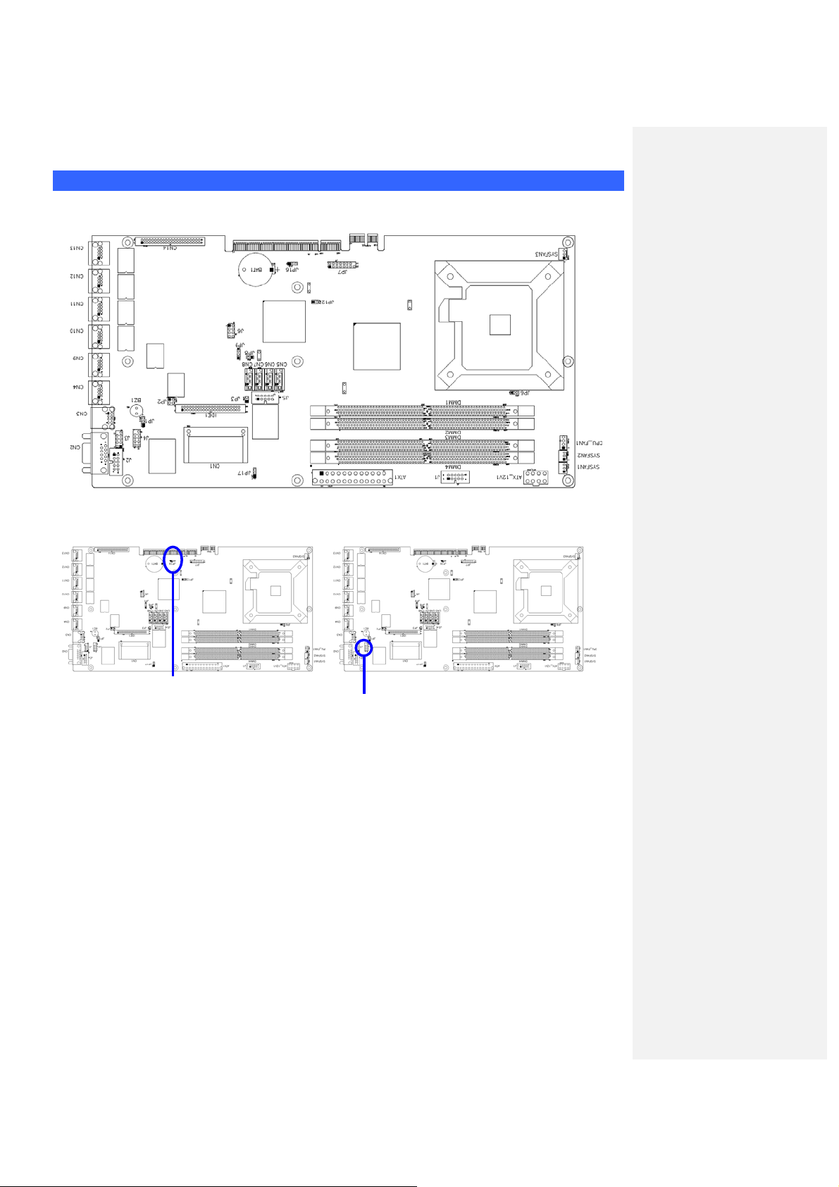
CPU board layout
Jumper Setting
Chapter 3 Hardware Configuration
JP16: Clear CMOS Contents JP1, JP2: Watchdog Timer & LAN1/LAN2 Bypass Settings
JP16:1-2 Normal (Default) JP1 & JP2 : JP2 Pin 1-2 & 3-4 Open JP1 Pin 1-2 Closed
2-3 Clear CMOS
System LANs bypass function controlled by SIO
JP1 & JP2 : JP2 Pin 1-2 & 3-4 ClosedJP1 Pin 1-2 Closed (Default)
System will bypass LANs upon the time
JP1 & JP2 :
System will reboot upon the time out of watchdog
out of watchdog timer
JP2 Pin 1-2 & 3-4 OpenJP1 Pin 2-3 Closed
GPIO15.
timer.
Page 7
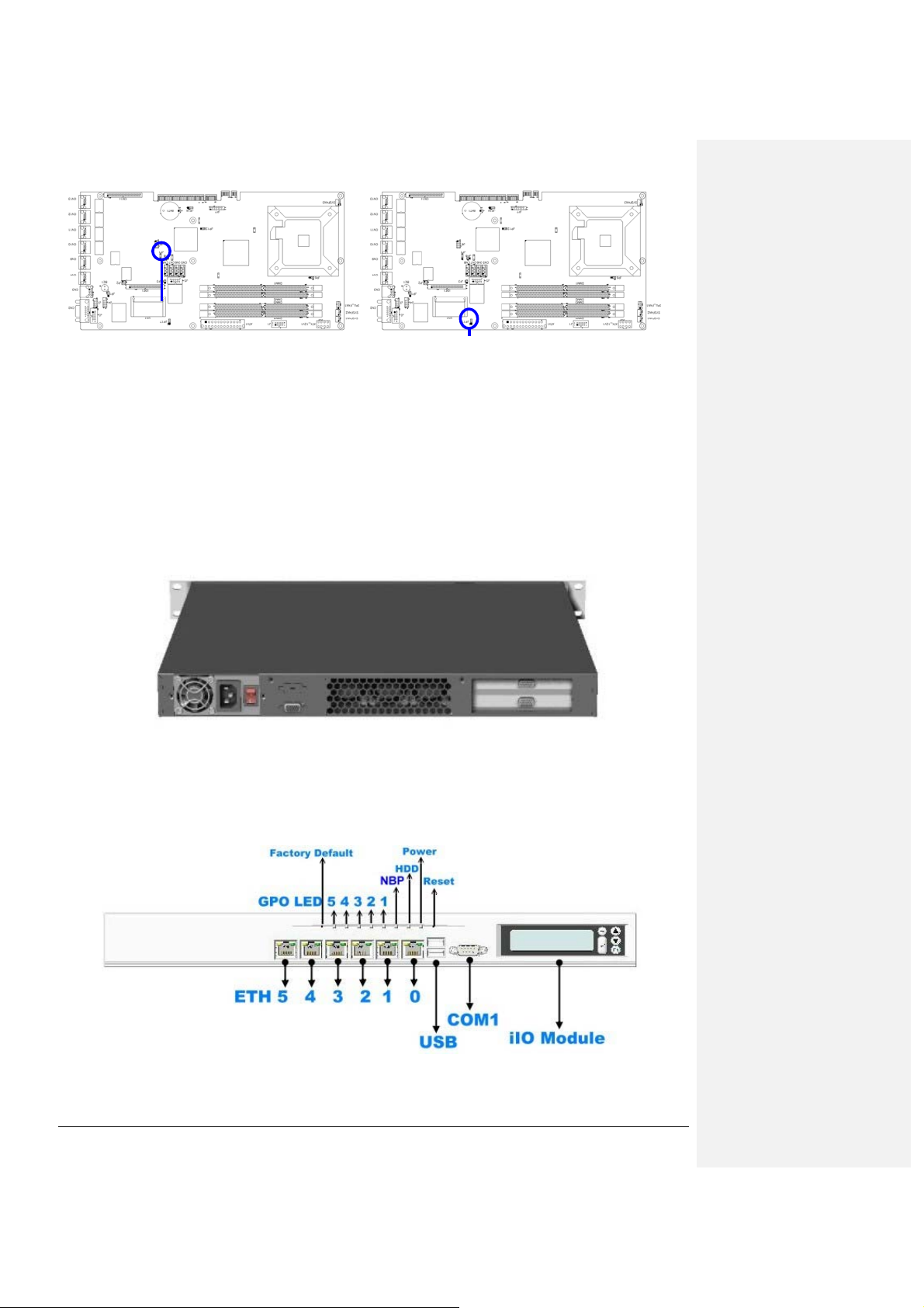
JP9 : Configure and Recovery (Factory use only) JP17:Power ON Setting
Pin 1-2 Short/Closed:
Pin 2-3 Short/Closed: Configure Pin 2-3 Short/Closed: Power on by system button
Open: Recovery
Normal (default) Pin 1-2 Short/Closed: Power on by power supply AC
on
Rear Panel Features
Front Panel Features
Note :
The NBP LED means None ByPass function.
If NBP LED turns on, it indicates Normal mode.
If NBP LED turns off, it indicates Bypass mode.
FWA8206 Series User’s Manual
1
Page 8
2
Chapter 4 Console Mode Information
FWA8206 supports output information via Console in BIOS le vel.
Prepare a computer as client loaded with an existing OS such Windows XP.
Connect client computer and FWA8206 with NULL Modem cable.
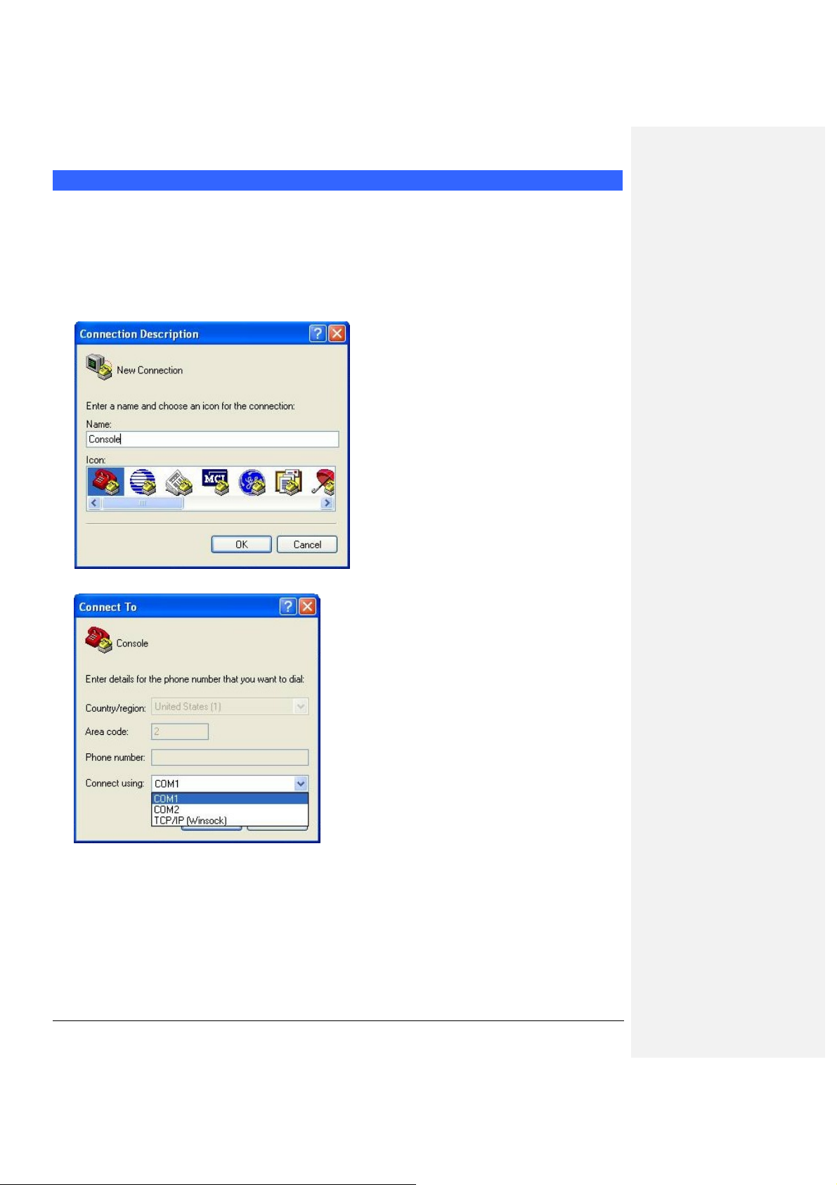
Follow the steps below to configure the Windows Hyper Terminal application setting:
1. For executing the Hyper Terminal, issue command “hypertrm”.
2. Customize your name for the new connection.
3. Choose the COM port on the client computer for the connection.
4. Please make the port settings to Baud rate 19200, Parity None, Data bits 8, Stop bits 1
FWA8206 Series User’s Manual
Page 9
3
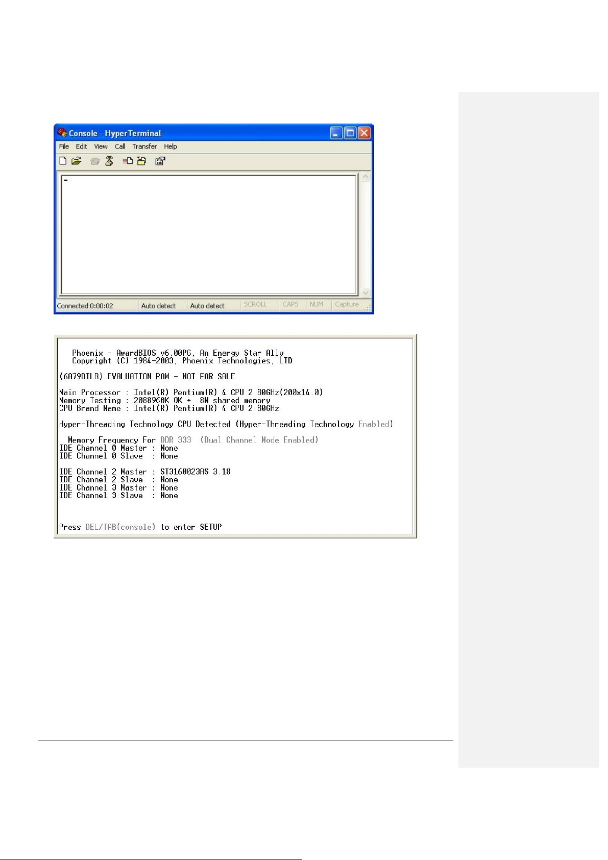
5. Power up the FWA8206, and the screen will display the following information.
6. Press <Tab> key to enter BIOS setup screen in Console mode.
Press <Del> key to enter BIOS setup screen in VGA mode.
FWA8206 Series User’s Manual
Page 10
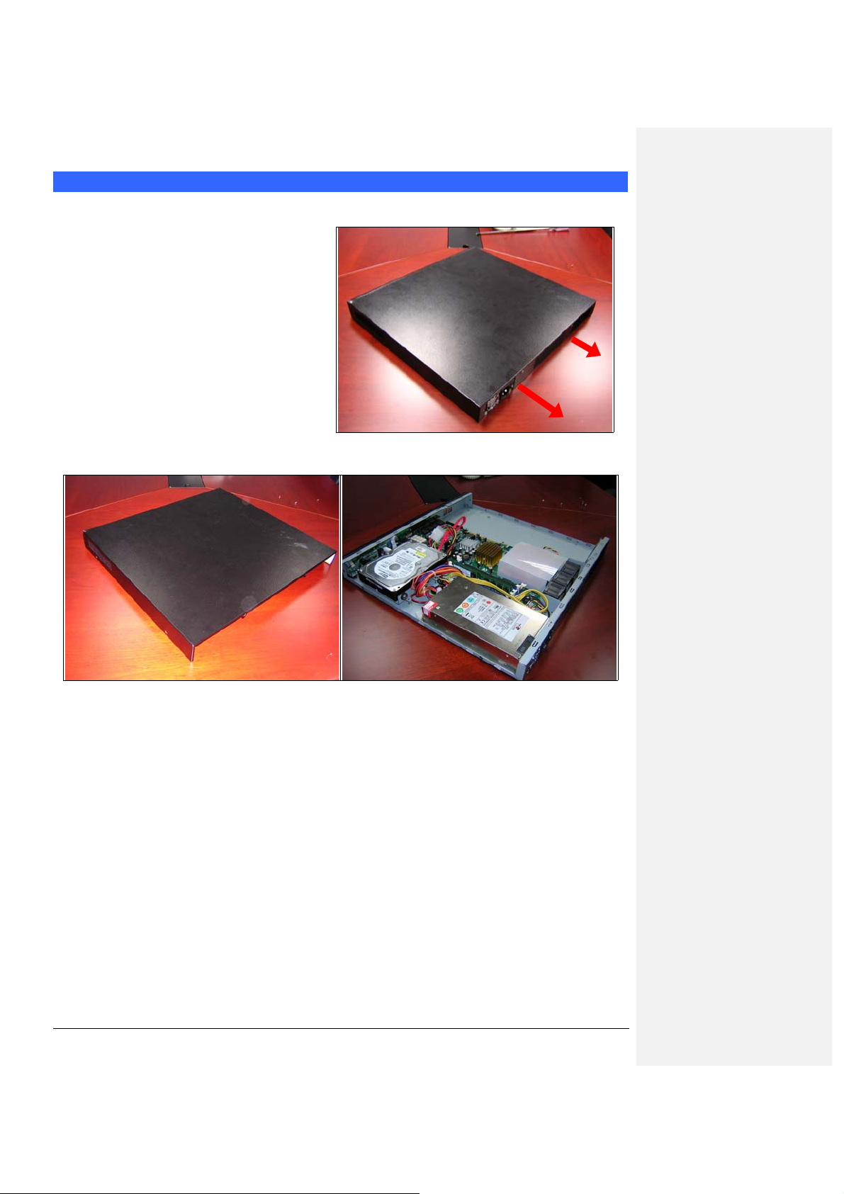
Chapter 5 Open the chassis
1. Loosen the two screws of the chassis
on the back to remove the top lead
(Fig. 5-1).
Fig. 5-1 Take off screws
2. The top lead (Fig. 5-2) can be remo ved from the base stand (Fig. 5-3).
Fig. 5-2 The top lead Fig. 5-3 The base stand
FWA8206 Series User’s Manual
4
Page 11
5
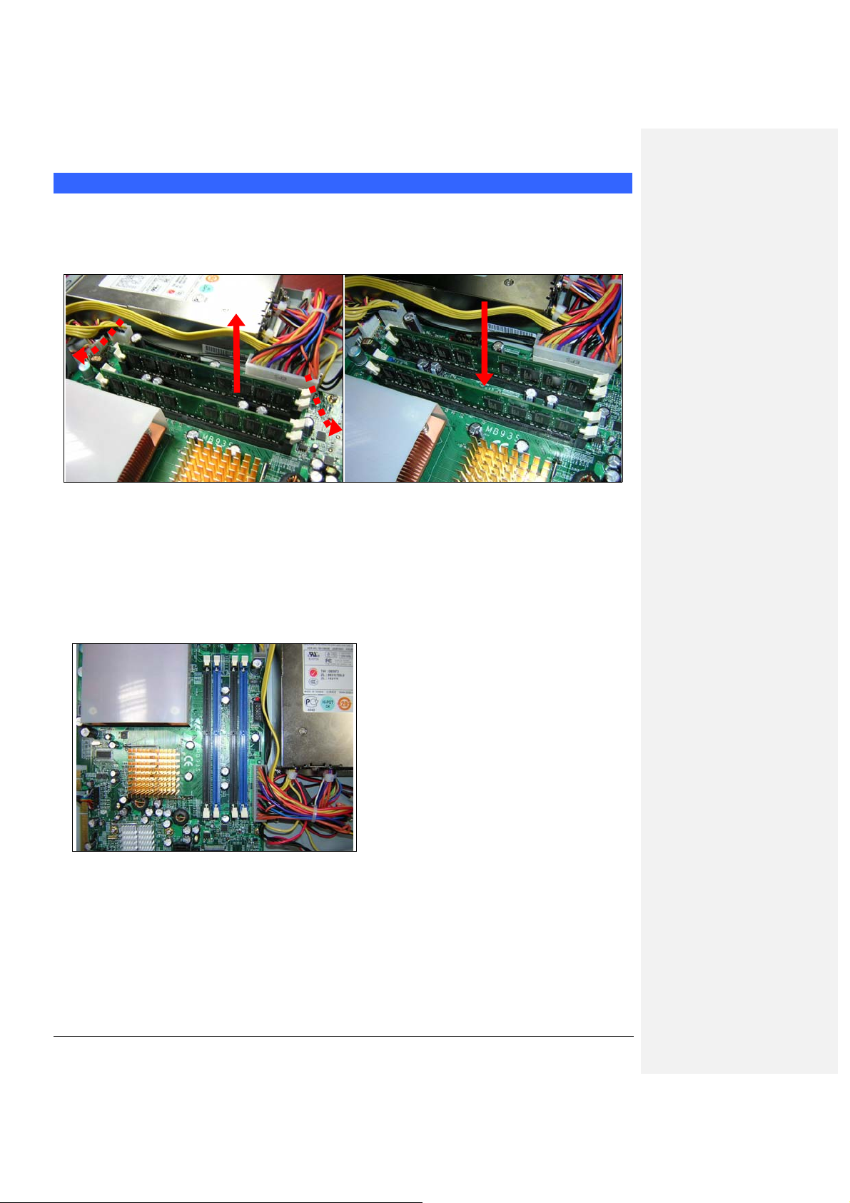
Chapter 6 Removing and Installing DIMM
Follow these steps to upgrade RAM module:
1. Install the system memory by pulling the socket’s arm a nd pressing it into the slot gently.
(Fig. 6-1, 6-2)
Fig. 6-1 Eject a DIMM module Fig. 6-2 Install DIMM
Note:
1. FWA8206 series support two groups of dual channels memory.
One group is on the black DIMM sockets and the other one is on the blue DIMM sockets.
(Fig. 6-3)
2. If you would like to upgrade the memory modules, we suggest the height of memory
modules don’t exceed 30mm.
Fig. 6-3 DIMM sockets
FWA8206 Series User’s Manual
Page 12

Chapter 7 Removing and Installing CompactFlash Card
1. Insert the Compact Flash Card (Fig. 7-1) into the CF interface (Fig. 7-2).
Fig. 7-1 Compact Flash Card Fig. 7-2 Insert Compact Flash Card into the CF
interface
3.
2. The completed installation of
CompactFlash Card is shown
in Fig. 7-3.
Fig. 7-3 Completion of Compact Flash C ard
connection
格式化: 項目符號及編號
Page 13

Chapter 8 Removing and Installing the Battery
1. Press the metal clip back to eject the button battery (Fig. 8-1).
2. Replace it with a new one by pressing the battery wi th finge rtip to restore the b attery (Fig . 8- 2).
Fig. 8-1 Eject the battery Fig. 8-2 Restore the battery
FWA8206 Series User’s Manual
Chapter 9 Installing the 3.5” HDD
1
Page 14

2
Follow the steps below to install the 3.5” HDD:
Fig. 9-1 Push the four shock-absorbent pads to
fasten HDD bracket.
Fig. 9-3 Connect SATA cable and power
connector to 3.5” HDD
Fig. 9-2 Fasten the four screws to lock HDD and
bracket together.
Fig. 9-4 Connect SATA cable to MB935
Fig. 9-5 Fixed HDD bracket and Fix two
screws back
FWA8206 Series User’s Manual
Page 15
3
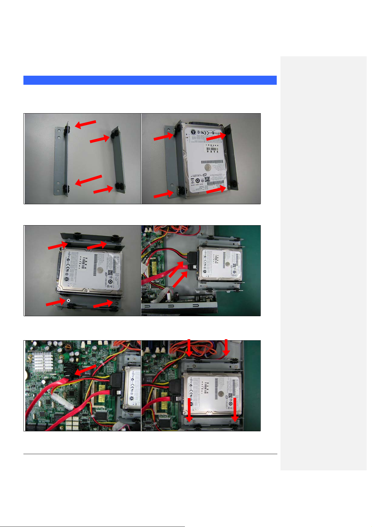
Chapter 10 Install 2.5” HDD
Follow the steps below to install the 2.5” HDD:
Fig. 10-1 Push the eight shock-absorbent pads
to fasten HDD bracket.
Fig. 10-2 Fasten the four screws to lock 2.5”
HDD bracket and bracket together.
Fig. 10-3 Fasten the four screws to lock 2.5”
HDD and bracket together.
Fig. 10-4 Connect SATA cable and power
connector to 2.5” HDD
Fig. 10-5 Connect SATA cable to MB935 Fig. 10-6 Fixed HDD bracket and Fix two screws
back
FWA8206 Series User’s Manual
Page 16

Chapter 1 1 BIOS Information
Phoenix - AwardBIOS CMOS Setup Utility
Standard CMOS Features Frequency/Voltage Control
Advanced BIOS Features Load Fail-Safe Defaults
Advanced Chipset
Features
Integrated Peripherals Set Supervisor Password
Power Management Setup Set User Password
PnP/PCI Configurations Save & Exit Setup
PC Health Status Exit Without Saving
ESC : Quit Ç È Æ Å : Select Item
F10 : Save & Exit Setup
Time, Date, Hard Disk Type…
The section below the setup items of the Main Menu displays the control keys for this menu. At the bottom of the
Main Menu just below the control keys section, there is another section, which displays information on the currently
highlighted item in the list.
Note: If the system cannot boot after making and saving
system changes with Setup, the Award BIOS supports
an override to the CMOS settings that resets your
system to its default.
Warning: It is strongly recommended that you avoid making any
changes to the chipset defaults. These defaults have
been carefully chosen by both Award and your system
manufacturer to provide the absolute maximum
performance and reliability. Changing the defaults
could cause the system to become unstable and crash
in some cases.
Standard CMOS Setup
“Standard CMOS Setup” choice allows you to record some basic hardware configurations in your computer system
and set the system clock and error handling. If the motherboard is already installed in a working system, you will not
need to select this option. You will need to run the Standard CMOS option, however, if you change your system
hardware configurations, the onboard battery fails, or the configuration stored in the CMOS memory was lost or
damaged.
Date (mm:dd:yy) Thu, May 21, 2001 Item Help
Time (hh:mm:ss) 00 : 00 : 00 Menu Level
IDE Channel 0 Master None Change the day, month,
IDE Channel 0 Slave None Year and century
IDE Channel 1 Master None
IDE Channel 1 Slave None
Video EGA/VGA
Halt On All Errors
Base Memory 640K
Extended Memory 129024K
Total Memory 130048K
At the bottom of the menu are the control keys for use on this menu. If you need any help in each item field, you
FWA8206 Series User’s Manual
Phoenix - AwardBIOS CMOS Setup Utility
Standard CMOS Features
Load Optimized Defaults
4
Page 17

5
can press the <F1> key. It will display the relevant information to help you. The memory display at the lower righthand side of the menu is read-only. It will adjust automatically according to the memory changed. The following
describes each item of this menu.
Date
The date format is:
Day : Sun to Sat
Month : 1 to 12
Date : 1 to 31
Year : 1994 to 2079
To set the date, highlight the “Date” field and use the PageUp/ PageDown or +/- keys to set the current time.
Time
The time format is: Hour : 00 to 23
Minute : 00 to 59
Second : 00 to 59
To set the time, highlight the “Time” field and use the <PgUp>/ <PgDn> or +/- keys to set the current time.
IDE Primary HDDs / IDE Secondary HDDs
The onboard PCI IDE connectors provide Primary and Secondary channels for connecting up to four IDE hard disks
or other IDE devices. Each channel can support up to two hard disks; the first is the “Master” and the second is the
“Slave”.
Press <Enter> to configure the hard disk. The selections include Auto, Manual, and None. Select ‘Manual’ to define
the drive information manually. You will be asked to enter the following items.
CYLS : Number of cylinders
HEAD : Number of read/write heads
PRECOMP : Write precompensation
LANDZ : Landing zone
SECTOR : Number of sectors
The Access Mode selections are as follows:
Auto
Normal (HD < 528MB)
Large (for MS-DOS only)
LBA (HD > 528MB and supports Logical Block Addressing)
Video
This field selects the type of video display card installed in your system. You can choose the following video display
cards:
EGA/VGA For EGA, VGA, SEGA, SVGA or PGA monitor adapters. (default)
CGA 40 Power up in 40 column mode.
CGA 80 Power up in 80 column mode.
MONO For Hercules or MDA adapters.
Halt On
This field determines whether or not the system will halt if an error is detected during power up.
No errors The system boot will not be halted for any error that may be detected.
All errors Whenever the BIOS detects a non-fatal error, the system will stop and you will be
prompted.
All, But Keyboard The system boot will not be halted for a keyboard error; it will stop for all other errors
All, But Diskette The system boot will not be halted for a disk error; it will stop for all other errors.
All, But Disk/Key The system boot will not be halted for a key- board or disk error; it will stop for all others.
Advanced BIOS Features
FWA8206 Series User’s Manual
Page 18

6
This section allows you to configure and improve your system and allows you to set up some system features
according to your preference.
Phoenix - AwardBIOS CMOS Setup Utility
Advanced BIOS Features
CPU Feature Press Enter ITEM HELP
Hard Disk Boot Priority Press Enter Menu Level
Virus Warning Disabled
CPU L1 and L2 Cache Enabled
CPU L3 Cache Enabled
Hyper-threading Technology Enabled
Quick Power On Self Test Enabled
First Boot Device USB-FDD Select Hard Disk Boot
Second Boot Device Hard Disk
Device Priority
Third Boot De vice LAN
Boot Other Device Enabled
Boot Up Numlock Status On
Gate A20 Option Fast
Typematic Rate Setting Disabled
Typematic Rate (chars/Sec) 6
Typematic Delay (Msec) 250
Security Option Setup
APIC Mode Enabled
MPS Version Control for OS 1.4
OS Select For DRAM>64MB Non-OS2
Console Redirection Enable
Baud Rate 19200
Agent connect via NULL
Agent wait time(min) 1
Agent after boot Disabled
Report No FDD For WIN 95 Yes
Small Logo (EPA) Show Enabled
Hard Disk Boot Priority
This item allows you to set the priority for hard disk boot. When you press enter, the selections shows the current
hard disks used in your system as well as the “Bootable Add-in Card” that is relevant to other boot sources media
such as SCSI cards and LAN cards.
CPU L1 and L2 Cache
Cache memory is additional memory that is much faster than conventional DRAM (system memory). CPUs from
486-type on up contain internal cache memory, and most, but not all, modern PCs have additional (external) cache
memory. When the CPU requests data, the system transfers the requested data from the main DRAM into cache
memory, for even faster access by the CPU. These items allow you to enable (speed up memory access) or disable
the cache function. By default, these items are Enabled.
Hyper-Threading Technology
This feature is enabled when your processor supports Hyper-Threading Technology. Otherwise, this field will be
hidden.
Quick Power On Self Test
When enabled, this field speeds up the Power On Self Test (POST) after the system is turned on. If it is set to
Enabled, BIOS will skip some items.
First/Second/Third Boot Device
These fields determine the drive that the system searches first for an operating system. The options available
include Floppy, LS120, Hard Disk, CDROM, ZIP100, USB-FDD, USB-CDROM and Disable.
Boot Other Device
These fields allow the system to search for an operating system from other devices other than the ones selected in
the First/Second/Third Boot Device.
Boot Up NumLock Status
FWA8206 Series User’s Manual
Page 19

This allows you to activate the NumLock function after you power up the system.
Gate A20 Option
This field allows you to select how Gate A20 is worked. Gate A20 is a device used to address memory above 1 MB.
Typematic Rate Setting
When disabled, continually holding down a key on your keyboard will generate only one instance. When enabled,
you can set the two typematic controls listed next. By default, this field is set to Disabled.
Typematic Rate (Chars/Sec)
When the typematic rate is enabled, the system registers repeated keystrokes speeds. Settings are from 6 to 30
characters per second.
Typematic Delay (Msec)
When the typematic rate is enabled, this item allows you to set the time interval for displaying the first and second
characters. By default, this item is set to 250msec.
Security Option
This field allows you to limit access to the System and Setup. The default value is Setup. When you select System,
the system prompts for the User Password every time you boot up. When you select Setup, the system always
boots up and prompts for the Supervisor Password only when the Setup utility is called up.
APIC Mode
APIC stands for Advanced Programmable Interrupt Controller. The default setting is Enabled.
MPS Version Control for OS
This option is specifies the MPS (Multiprocessor Specification) version for your operating system. MPS version 1.4
added extended configuration tables to improve support for multiple PCI bus configurations and improve future
expandability. The default setting is 1.4.
OS Select for DRAM > 64MB
This option allows the system to access greater than 64MB of DRAM memory when used with OS/2 that depends
on certain BIOS calls to access memory. The default setting is Non-OS/2.
Console Redirection
Set the Console Redirection from COM port to UNIX terminal on BIOS boot up.
Default : Enabled
Baud Rate
The default value of the Baud Rate is 19200.
Agent Connect Via
By default, this item is set to NULL.
Agent Wait Time (min)
By default, the Agent Wait Time is set to 1 minute.
Agent After Boot
By default, this field is disabled.
Report No FDD For WIN 95
If you are using Windows 95/98 without a floppy disk drive, select Enabled to release IRQ6. This is required to pass
Windows 95/98's SCT test. You should also disable the Onboard FDC Controller in the Integrated Peripherals
screen when there's no floppy drive in the system. If you set this feature to Disabled, the BIOS will not report the
missing floppy drive to Win95/98.
Small Logo (EPA) Show
The EPA logo appears at the right side of the monitor screen when the system is boot up. The default setting is
Disabled.
Advanced Chipset Features
FWA8206 Series User’s Manual
7
Page 20

8
This Setup menu controls the configuration of the chipset.
Phoenix - AwardBIOS CMOS Setup Utility
Advanced Chipset Features
DRAM Timing Selectable By SPD ITEM HELP
CAS Latency Time Auto Menu Level
DRAM RAS# to CAS# Delay Auto
DRAM RAS# Precharge Auto
Precharge Delay Auto
SLP_S4# Assertion Width
System Memory Frequency Auto
System BIOS Cacheable Enabled
Video BIOS Cacheable Enabled
Memory Hole at 15M-16M Disabled
PCI Express Root Press Enter
On-Chip Video Memory Press Enter
On-Chip Frame Buffer Size Memory 8MB
DVMT Version DVMT 3.0
FIXED Memory Size 64MB
DVMT Memory Size 64MB
Boot Display Auto
DRAM Timing Selec table
This option refers to the method by which the DRAM timing is selected. The default is By SPD.
CAS Latency Time
You can configure CAS latency time in HCLKs as 2 or 2.5 or 3. The system board designer should set the values in
this field, depending on the DRAM installed. Do not change the values in this field unless you change specifications
of the installed DRAM or the installed CPU.
DRAM RAS# to CAS# Delay
This option allows you to insert a delay between the RAS (Row Address Strobe) and CAS (Column Address Strobe)
signals. This delay occurs when the SDRAM is written to, read from or refreshed. Reducing the delay improves the
performance of the SDRAM.
DRAM RAS# Precharge
This option sets the number of cycles required for the RAS to accumulate its charge before the SDRAM refreshes.
The default setting for the Active to Precharge Delay is Auto.
Precharge Delay
The default setting for the Precharge Delay is Auto.
System Memory Frequency
This field sets the frequency of the DRAM memory installed. The default setting is Auto. The other settings are
DDR266, DDR333, DDR320 and DDR400.
System BIOS Cacheable
The setting of Enabled allows caching of the system BIOS ROM at F000h-FFFFFh, resulting in better system
performance. However, if any program writes to this memory area, a system error may result.
Video BIOS Cacheable
The Setting Enabled allows caching of the video BIOS ROM at C0000h-F7FFFh, resulting in better video
performance. However, if any program writes to this memory area, a system error may result.
Memory Hole At 15M-16M
In order to improve performance, certain space in memory can be reserved for ISA cards. This memory must be
On-Chip Frame Buffer Size Memory
Allow user to select the amount of system memory pre-allocated by the internal graphics device.
Phoenix - AwardBIOS CMOS Setup Utility
FWA8206 Series User’s Manual
Page 21

Integrated Peripherals
On-Chip IDE Device
Onboard Device
SuperIO Device
Onboard LAN Boot
2nd SuperIO Device
IDE Block Mode
IDE DMA transfer access
On-Chip Primary PCI IDE
IDE Primary Master PIO
IDE Primary Slave PIO
IDE Primary Master UDMA
IDE Primary Slave UDMA
On-Chip Secondary PCI IDE
IDE Secondary Master PIO
IDE Secondary Slave PIO
IDE Secondary Master
UDMA
IDE Secondary Slave
UDMA
*** On-Chip Serial ATA Setting ***
SATA Mode
On-Chip Serial ATA
Serial ATA Port0 Mode
Serial ATA Port1 Mode SATA1 master
USB Controller
USB 2.0 Controller
USB Keyboard Support
AC97 Audio Auto
Power On Function BUTTON ONLY
KB Power On Password Enter
Hot Key Power On Ctrl-F1
Onboard FDC Controller Enabled
Onboard Serial Port 1 3F8/IRQ4
Onboard Serial Port 2 2F8/IRQ3
UART Mode Select Normal
RxD , TxD Active Hi, Lo
IR Transmission Delay Enabled
UR2 Duplex Mode Half
Use IR Pins IR-Rx2Tx2
PWRON After PWR-Fail On
Press Enter ITEM HELP
Press Enter Menu Level
Press Enter
Press Enter
Press Enter
Phoenix - AwardBIOS CMOS Setup Utility
OnChip IDE Device
Enabled ITEM HELP
Enabled Menu Level
Enabled
Auto If your IDE hard drive
Auto
Auto
Auto
Enabled
Auto
Auto
Auto
Auto
IDE
Auto
SATA0 master
Phoenix - AwardBIOS CMOS Setup Utility
Onboard Device
Enabled ITEM HELP
Enable Menu Level
Enable
Phoenix - AwardBIOS CMOS Setup Utility
SuperIO Device
supports block mode select
Enabled for automatic
detection of the optimal
number of block read/writes
per sector the drive can
support
ITEM HELP
Menu Level
IDE HDD Block Mode
FWA8206 Series User’s Manual
9
Page 22

0
This field allows your hard disk controller to use the fast block mode to transfer data to and from your hard disk
drive.
IDE DMA Transfer Access
Allows IDE transfer to be done in DMA mode
OnChip Primary/Secondary PCI IDE
The integrated peripheral controller contains an IDE interface with support for two IDE channels. Select Enabled to
activate each channel separately.
IDE Primary/Secondary Master/Slave PIO
These fields allow your system hard disk controller to work faster. Rather than have the BIOS issue a series of
commands that transfer to or from the disk drive, PIO (Programmed Input/Output) allows the BIOS to communicate
with the controller and CPU directly.
The system supports five modes, numbered from 0 (default) to 4, which primarily differ in timing. When Auto is
selected, the BIOS will select the best available mode.
IDE Primary/Secondary Master/Slave UDMA
These fields allow your system to improve disk I/O throughput to 33Mb/sec with the Ultra DMA/33 feature. The
options are Auto and Disabled.
USB Controller
The options for this field are Enabled and Disabled. By default, this field is set to Enabled.
USB 2.0 Controller
The options for this field are Enabled and Disabled. By default, this field is set to Enabled. In order to use USB 2.0,
necessary OS drivers must be installed first.
USB Keyboard Support
The options for this field are Enabled and Disabled. By default, this field is set to Enabled.
AC97 Audio
The default setting of the AC97 Audio is Auto.
Onboard FDC Controller
Select Enabled if your system has a floppy disk controller (FDC) installed on the motherboard and you wish to use
it. If you install an add-in FDC or the system has no floppy drive , select Disabled in this field. This option allows you
to select the onboard FDD port.
UART Mode Select
This field determines the UART 2 mode in your computer. The default value is Normal. Other options include IrDA
and ASKIR.
Onboard LAN Boot
Enable or Disable the Marvell 88E8053 PXE Boot ROM.
Power Management Setup
FWA8206 Series User’s Manual
1
Page 23

The Power Management Setup allows you to save energy of your system effectively.
Phoenix - AwardBIOS CMOS Setup Utility
Power Management Setup
ACPI Function
Power Management
Video Off Method
Video Off In Suspend
Suspend Type
Modem Use IRQ
Suspend Mode
HDD Power Down
Soft-Off by PWR-BTTN
CPU THRM-Throttling
Wake-Up by PCI Car d
Power On by Ring
Wake Up on Lan
Resume by Alarm
Enabled ITEM HELP
User Define Menu Level
V/H SYNC+Blank
Yes
Stop Grant
3
Disabled
Disabled
Instant-Off
50%
Disabled
Disabled
Disabled
Disabled
Date (of Month) Alarm 0
Time (hh:mm:ss) Alarm 0 : 0 : 0
** Reload Global Timer
Events **
Primary IDE 0
Primary IDE 1
Secondary IDE 0
Secondary IDE 1
FDD, COM, LPT Port
PCI PIRQ[A-D] #
Enabled
Enabled
Enabled
Enabled
Enabled
Enabled
ACPI Function
Enable this function to support ACPI (Advance Configuration and Power Interface).
Power Management
This field allows you to select the type of power saving management modes. There are four selections for Power
Management.
Min. Power Saving Minimum power management
Max. Power Saving Maximum power management.
User Define Each of the ranges is from 1 min.
to 1hr. Except for HDD Power
Down which ranges from 1 min. to
15 min.
Video Off Method
This field defines the Video Off features. There are three options.
V/H SYNC + Blank Default setting, blank the scr een and tur n off vertical and horizontal scanning.
DPMS Allows BIOS to control the video display.
Blank Screen Writes blanks to the video buffer.
Video Off In Suspend
When enabled, the video is off in suspend mode. The default setting is Yes.
Suspend Type
The default setting for the Suspend Type field is Stop Grant.
Modem Use IRQ
This field sets the IRQ used by the Modem. By default, the setting is 3.
Suspend Mode
When enabled, and after the set time of system inactivity, all devices except the CPU will be shut off.
HDD Power Down
FWA8206 Series User’s Manual
11
Page 24

2
When enabled, and after the set time of system inactivity, the hard disk drive will be powered down while all other
devices remain active.
Soft-Off by PWRBTN
This field defines the power-off mode when using an ATX power supply. The Instant Off mode allows powering off
immediately upon pressing the power button. In the Delay 4 Sec mode, the system powers off when the power
button is pressed for more than four seconds or enters the suspend mode when pressed for less than 4 seconds.
CPU THRM-Throttling
When the system enters Doze mode, the CPU clock runs only part of the time. You may select the percent of time
that the clock runs.
Wake-Up by PCI Cards
Enable this field to allow wake up function through a PCI card.
Power On by Ring
This field enables or disables the power on of the system through the modem connected to the serial port or LAN.
Wake Up On LAN
Enable this field to allow wake up function through the onboard LAN.
Resume by Alarm
This field enables or disables the resumption of the system operation. When enabled, the user is allowed to set the
Date and Time.
Reload Global Timer Events
The HDD, FDD, COM, LPT Ports, and PCI PIRQ are I/O events that can prevent the system from entering a power
saving mode or can awaken the system from such a mode. When an I/O device wants to gain the attention of the
operating system, it signals this by causing an IRQ to occur. When the operating system is ready to respond to the
request, it interrupts itself and performs the service.
PNP/PCI Configurations
This option configures the PCI bus system. All PCI bus systems on the system use INT#, thus all installed PCI
cards must be set to this value.
PNP OS Install
Reset Configuration Data
Resources Controlled By
IRQ Resources
DMA Resources
PCI/VGA Palette Snoop
INT Pin 1 Assignment
INT Pin 2 Assignment
INT Pin 3 Assignment
INT Pin 4 Assignment
INT Pin 5 Assignment
INT Pin 6 Assignment
INT Pin 7 Assignment
INT Pin 8 Assignment
PNP OS Install
Enable the PNP OS Install option if it is supported by the operating system installed. The default value is No.
Reset Configuration Data
This field allows you to determine whether to reset the configuration data or not. The default value is Disabled.
Resources Controlled by
FWA8206 Series User’s Manual
Phoenix - AwardBIOS CMOS Setup Utility
PnP/PCI Configurations
No ITEM HELP
Disabled Menu Level
Auto (ESCD)
Press Enter
Press Enter
Disabled
Auto
Auto
Auto
Auto
Auto
Auto
Default is Disabled.
Select Enabled to reset
Extended System
Configuration Data
(ESCD) when you exit
Setup if you have
installed a new add-on
and the system
reconfiguration has
caused such a serious
conflict that the OS
cannot boot
Auto
Auto
1
Page 25

3
This PnP BIOS can configure all of the boot and compatible devices automatically with the use of a use a PnP
operating system such as Windows 95.
PCI/VGA Palette Snoop
Some non-standard VGA display cards may not show colors properly. This field allows you to set whether or not
MPEG ISA/VESA VGA cards can work with PCI/VGA. When this field is enabled, a PCI/VGA can work with an
MPEG ISA/VESA VGA card. When this field is disabled, a PCI/VGA cannot work with an MPEG ISA/VESA card.
PC Health Status
This section shows the parameters in determining the PC Health Status. These parameters include temperatures,
fan speeds and voltages.
Phoenix - AwardBIOS CMOS Setup Utility
PC Health Status
CPU Warning Temperature Disabled
Current System Temp.
Current CPU1 Temp
Vcore (V)
+3.3V
+5V
+12V
-12V
VBAT
5VSB(V)
Menu Level
Shutdown Temperature Disabled
Current CPUFAN1 Speed
Current CPUFAN2 Speed
Current CPUFAN3 Speed
Current CPUSYS1 Speed
1st Smart Fan II Temperature
Level2 Temperature
2nd Smart Fan II Temperature
Level2 Temperature
ITEM HELP
CPU Warning Temperature
This field allows the user to set the temperature so that when the temperature is reached, the system sounds a
warning. This function can help prevent damage to the system that is caused by overheating.
Temperatures/Fan Speeds/Voltages
These fields are the parameters of the hardware monitoring function feature of the motherboard. The values are
read-only values as monitored by the system and show the PC health status.
Shutdown Temperature
This field allows the user to set the temperature by which the system automatically shuts down once the threshold
temperature is reached. This function can help prevent damage to the system that is caused by overheating.
1st Smart Fan II Temperature (SYS_FAN1 connector)
FWA8206 Series User’s Manual
1
Page 26

Enable or Disable the first phase Smart FAN functionality of SYS_FAN1 connector.
Configuration option: [30 ] ℃ [35 ] ℃ [40 ] ℃ [45 ] ℃ [50 ] ℃ [55 ] ℃ [60 ]℃
If the value is set, the fan turns to 25% duty cycle when the temperature of CPU reach to the value.
The default value is Disable.
2nd Smart Fan II Temperature (CPU_FAN1 / CPU_FAN2 / CPU_FAN3 connectors)
Enable or Disable the first phase Smart FAN functionality of CPU_FAN1/CPU_FAN2/CPU_FAN3 connectors.
Configuration option: [30 ] ℃ [35 ] ℃ [40 ] ℃ [45 ] ℃ [50 ] ℃ [55 ] ℃ [60 ]℃
If the value is set, the fan turns to 25% duty cycle when CPU has reached temperature of approximately value.
The default value is [30 ]℃ .
Level2 Temperature
Set the second phase Smart FAN functionality.
Configuration option: [5 ] ℃ [10 ] ℃ [15 ] ℃
If both the value and the Smart Fan II Temperature are set, the fan turns to 50% duty cycle when CPU has
reached temperature of approximately (first phase + second phase temperature).
The third phase Smart FAN functionality:
If the CPU is over temperature of approximately (first phase + second phase temperature + 10℃), the fan turns to
75% duty cycle.
The final phase Smart FAN functionality:
If the CPU is over temperature of approximately (first phase + second phase temperature + 20℃), the fan turns to
100% duty cycle.
Frequency/Voltage Control
FWA8206 Series User’s Manual
14
Page 27

5
This section shows the user how to configure the processor frequency.
Phoenix - AwardBIOS CMOS Setup Utility
Frequency/Voltage Control
CPU Clock Ratio
Auto Detect DIMM/PCI Clk
Spread Spectrum
ITEM HELP
Enable
Disabled Menu Level
Auto Detect DIMM/PCI Clk
This field enables or disables the auto detection of the PCI clock.
Spread Spectrum
This field sets the value of the spread spectrum. The default setting is Disabled. This field is for CE testing use
only.
Load Fail-Safe Defaults
This option allows you to load the troubleshooting default values permanently stored in the BIOS ROM. These
default settings are non-optimal and disable all high-performance features.
Load Setup Defaults
This option allows you to load the default values to your system configuration. These default settings are optimal
and enable all high performance features.
Set Supervisor/User Password
These two options set the system password. Supervisor Password sets a password that will be used to protect the
system and Setup utility. User Password sets a password that will be used exclusively on the system. To specify a
password, highlight the type you want and press <Enter>. The Enter Password: message prompts on the screen.
Type the password, up to eight characters in length, and press <Enter>. The system confirms your password by
asking you to type it again. After setting a password, the screen automatically returns to the main screen.
To disable a password, just press the <Enter> key when you are prompted to enter the password. A message will
confirm the password to be disabled. Once the password is disabled, the system will boot and you can enter Setup
freely.
Save & Exit Setup
This option allows you to determine whether or not to accept the modifications. If you type “Y”, you will quit the
setup utility and save all changes into the CMOS memory. If you type “N”, you will return to Setup utility.
Exit Without Saving
Select this option to exit the Setup utility without saving the changes you have made in this session. Typing “Y” will
quit the Setup utility without saving the modifications. Typing “N” will return you to Setup utility.
FWA8206 Series User’s Manual
1
Page 28

6
Chapter 12 Bypass Information
If jumpers are removed from JP4 leaving 1-2 & 3-4 to open status, ETH 0 & ETH1 will be under
Bypass mode (Bypass LED off).
User could initiate it to the Normal mode (Bypass LED light up) then re-trigger it in a loop.
Once the system hangs, ETH0 & ETH1 will switch to Bypass mode after timeout.
The following is the example code for the Bypass function.
#include <stdio.h>
#include <stdlib.h>
#include <string.h>
#include <unistd.h>
#include <errno.h>
#include <fcntl.h>
#include <sys/time.h>
#include <sys/types.h>
#include <sys/stat.h>
#include <asm/io.h> /* linux-specific */
#ifdef __GLIBC__
# include <sys/perm.h>
#endif
void by_pass_init (void) {
unsigned int i=0;
outb(0x87,0x4e);//Enter extended function mode
outb(0x87,0x4e);
outb(0x2b,0x4e);
i = inb(0x4f);
i &= 0xef;//Configure bit 4 as 0 to be watchdog function.
outb(0x2b,0x4e);
outb(i,0x4f);
outb(0x7,0x4e);
outb(0x8,0x4f);//watchdog in logic device 8
outb(0x30,0x4e);//Active wdt
outb(0x1,0x4f);
outb(0xf5,0x4e);
i = inb(0x4f);
i &= 0xf7;
outb(0xf5,0x4e);
outb(i,0x4f);
outb(0xf6,0x4e);
outb(1,0x4f);//Set timeout value to inital the normal mode.
outb(0xf7,0x4e);
outb(0x0,0x4f);
outb(0xaa,0x4e); // Exit extended mode
FWA8206 Series User’s Manual
1
Page 29

7
sleep(1);
}
#define TIMEOUT 10
void enable_wdt (void) {
unsigned int i=0;
outb(0x87,0x4e);//Enter extended function mode
outb(0x87,0x4e);
outb(0x2b,0x4e);
i = inb(0x4f);
i &= 0xef;//Configure bit 4 as 0 to be watchdog function.
outb(0x2b,0x4e);
outb(i,0x4f);
outb(0x7,0x4e);
outb(0x8,0x4f);//watchdog in logic device 8
outb(0x30,0x4e);//Active wdt
outb(0x1,0x4f);
outb(0xf5,0x4e);
i = inb(0x4f);
/*Select watchdog count mode */
//i = i | 0x8; //Select minute
i = i & 0xf7; //Select second
outb(0xf5,0x4e);
outb(i,0x4f);
outb(0xf6,0x4e);
outb(TIMEOUT,0x4f);
outb(0xf7,0x4e);
outb(0x0,0x4f);
}
void retrigger ( void ) {
outb(0xf6,0x4e);
outb(TIMEOUT,0x4f);
}
/* Disable WDT function */
void dis_wdt ( void ) {
outb(0xf6,0x4e);
outb(0x00,0x4f);
}
int main(int argc, char **argv)
{
int c;
setuid(0); /* if we're setuid, force it on */
FWA8206 Series User’s Manual
1
Page 30

8
if ( iopl(3) ) {
fprintf(stderr, "iopl(): %s\n", strerror(errno));
return -1;
}
by_pass_init();
/* Enable watchdog function and retrigger TIMEOUT countdown */
enable_wdt();
for(;;) {
sleep(1);/* Function check.
if timeout, switch to By Pass mode.
Or , call retrigger() for retrigger WDT. */
/* Display countdown */
outb(0xf6,0x4e);
c = inb(0x4f);
printf("Watchdog countdown %d\n",c);
if ( ! c ) {
printf("Switch to Bypass mode !\n");
break;
}
//retrigger();//retrigger watchdog
}
//dis_wdt();//Disable watchdog function
return 0;
}
FWA8206 Series User’s Manual
1
Page 31

Chapter 13 Factory Default Information
We offer a Factory Default Setting function for more flexibility.
The programmer could design a function such as loading the software default setting. It will
restore the software default setting after the user presses the Factory Default button.
The following is the example code for the Factory Defaul t Setting function.
#include <stdio.h>
#include <stdlib.h>
#include <string.h>
#include <unistd.h>
#include <errno.h>
#include <fcntl.h>
#include <sys/time.h>
#include <sys/types.h>
#include <sys/stat.h>
#include <asm/io.h> /* linux-specific */
#ifdef __GLIBC__
# include <sys/perm.h>
#endif
int fd_polling ( void ) {
unsigned int i=0;
//Enter Extended Function Mode
outb(0x87,0x4e);
outb(0x87,0x4e);
//Select logic device 7
outb(0x7,0x4e);
outb(0x7,0x4f);
//Assign GPIO1 (GP15)
outb(0x2a,0x4e);
i = inb(0x4f);
i |= 0x82;
outb(0x2a,0x4e);
outb(i,0x4f);
//Active logic device 7
outb(0x30,0x4e);
outb(0x1,0x4f);
//Select I/O mode
//Configure GP15 as an input port.
outb(0xf0,0x4e);
i = inb(0x4f);
i &= 0xff;
i |= 0x20;
outb(i,0x4f);
//Select inversion mode
outb(0xf2,0x4e);
i = inb(0x4f);
Page 32

i &= 0xdf;
outb(i,0x4f);
/* Value of Inversion Register :
Only high nibble is available for this function.
When set to a 1, the incoming/outgoing port value is inverted.
When set to a 0, the incoming/outgoing port value is the same as in Data Register.
Value of I/O Selection Register :
Only high nibble is available for this function.
When set to a 1, respective GPIO port is programmed as an input port.
When set to a 0, respective GPIO port is programmed as an output port.
Value of Output Data / Input Data :
Only high nibble is available for this function.
If a port is assigned to be an output port,then its respective bit can be read/written.
If a port is assigned to be an input port, then its respective bit can be read only.
*/
outb(0xf1,0x4e);
i = inb(0x4f);
i >>= 5;
return i;
}
int main( int argc , char **argv )
{
int status,i=0;
setuid(0); /* if we're setuid, force it on */
if ( iopl(3) ) {
fprintf(stderr, "iopl(): %s\n", strerror(errno));
return -1;
}
for(;;) {
usleep(10000);
status = fd_polling();
if ( status == 0 ) { // Check the Factory Default button
i++;
printf("### MB893 Load Default Setting (%d) ###\n",i);
usleep(500000);
//You could call your function here to load the
//software default value.
}
}
return 0;
}
FWA8206 Series User’s Manual
1
Page 33

2
Chapter 14 GPO LED Information
The following is an example code for the GPO LED function.
#include <stdio.h>
#include <stdlib.h>
#include <string.h>
#include <unistd.h>
#include <errno.h>
#include <fcntl.h>
#include <sys/time.h>
#include <sys/types.h>
#include <sys/stat.h>
#include <asm/io.h> /* linux-specific */
#ifdef __GLIBC__
# include <sys/perm.h>
#endif
void gpo_onoff ( unsigned int pos , int flag ) {
unsigned int led,i=0;
//Enter Extended Function Mode
outb(0x87,0x4e);
outb(0x87,0x4e);
//Select logic device 7
outb(0x7,0x4e);
outb(0x7,0x4f);
//Assign pin121-128 bit(7...2) to be 1
outb(0x2f,0x4e);
i = inb(0x4f);
i |= 0xfc;
outb(0x2f,0x4e);
outb(i,0x4f);
//Active logic device 7
outb(0x30,0x4e);
outb(0x1,0x4f);
//Select I/O mode
outb(0xf0,0x4e);
i = inb(0x4f);
i &= 0x3;
outb(0xf0,0x4e);
outb(i,0x4f);
//Select inversion mode
outb(0xf2,0x4e);
i = inb(0x4f);
i &= 0x3;
outb(0xf2,0x4e);
outb(i,0x4f);
FWA8206 Series User’s Manual
Page 34

3
/* Value of Inversion Register :
Only high nibble is available for this function.
When set to a 1, the incoming/outgoing port value is inverted.
When set to a 0, the incoming/outgoing port value is the same as in Data Register.
Value of I/O Selection Register :
Only high nibble is available for this function.
When set to a 1, respective GPIO port is programmed as an input port.
When set to a 0, respective GPIO port is programmed as an output port.
Value of Output Data / Input Data :
Only high nibble is available for this function.
If a port is assigned to be an output port,then its respective bit can be read/written.
If a port is assigned to be an input port, then its respective bit can be read only.
*/
switch (pos) {
case 1:
outb(0xf1,0x4e);//GP10 , LED1
led = inb(0x4f);
led &= 0xff;
led = ( flag==1 ?(led | 1) :(led & 0xfe));
outb(0xf1,0x4e);
outb(led,0x4f);
break;
case 2:
outb(0xf1,0x4e);//GP11 , LED2
led = inb(0x4f);
led &= 0xff;
led = ( flag==1 ?(led | 2) :(led & 0xfd));
outb(0xf1,0x4e);
outb(led,0x4f);
break;
case 3:
outb(0xf1,0x4e);//GP12 , LED3
led = inb(0x4f);
led &= 0xff;
led = ( flag==1 ?(led | 4) :(led & 0xfb));
outb(0xf1,0x4e);
outb(led,0x4f);
break;
case 4:
outb(0xf1,0x4e);//GP13 , LED4
led = inb(0x4f);
led &= 0xff;
led = ( flag==1 ?(led | 8) :(led & 0xf7));
outb(0xf1,0x4e);
outb(led,0x4f);
break;
case 5:
outb(0xf1,0x4e);//GP14 , LED5
led = inb(0x4f);
led &= 0xff;
led = ( flag==1 ?(led | 0x10) :(led & 0xef));
outb(0xf1,0x4e);
outb(led,0x4f);
break;
FWA8206 Series User’s Manual
Page 35

}
outb(0xaa,0x4e); // Exit extended function mode
}
#define ON 1
#define OFF 0
int main( int argc , char **argv )
{
setuid(0); /* if we're setuid, force it on */
if ( iopl(3) ) {
fprintf(stderr, "iopl(): %s\n", strerror(errno));
return -1;
}
for (;;) {
gpo_onoff(1,ON);
usleep(200000);
gpo_onoff(1,OFF);
usleep(200000);
gpo_onoff(2,ON);
usleep(200000);
gpo_onoff(2,OFF);
usleep(200000);
gpo_onoff(3,ON);
usleep(200000);
gpo_onoff(3,OFF);
usleep(200000);
gpo_onoff(4,ON);
usleep(200000);
gpo_onoff(4,OFF);
usleep(200000);
gpo_onoff(5,ON);
usleep(200000);
gpo_onoff(5,OFF);
usleep(200000);
}
return 0;
}
FWA8206 Series User’s Manual
4
Page 36

5
Chapter 15 System Architecture
The following block diagram illustrates a basic design reference of MB935, a highly integrat ed
system solution.
FWA8206 Series User’s Manual
 Loading...