

Page 1
FWA7404 Series
Network Appliance
Users Manual
Version: 1.0
Page 2

FWA7404 Series User’s Manual
1
Table of Contents
Chapter 1 Introduction .............................................................................................................. 3
Chapter 2 System Specification .............................................................................................. 4
Chapter 3 Hardware Configuration ......................................................................................... 5
Chapter 4 Console Mode Information ..................................................................................... 6
Chapter 5 Opening the chassis ............................................................................................... 8
Chapter 6 Removing and Installing CompactFlash Card .................................................... 9
Chapter 7 Installing the Mini-PCI card .................................................................................. 10
Chapter 8 Installing the 2.5” HDD.......................................................................................... 11
Chapter 9 System Architecture.............................................................................................. 12
Page 3

FWA7404 Series User’s Manual
2
Foreword
To prevent damage to the system board, please handle it with care and follow the measures below,
which are generally sufficient to protect your equipment from static electricity discharge:
When handling the board, use a grounded wrist strap designed for static discharge elimination grounded
to a metal object before removing the board from the antistatic bag. Handle the board by its edges only;
do not touch its components, peripheral chips, memory modules or gold contacts.
When handling processor chips or memory modules, avoid touching their pins or gold edge fingers.
Return the Network Appliance system board and peripherals back into the antistatic bag when not in use
or not installed in the chassis.
Some circuitry on the system board can continue to operate even though the power is switched off.
Under no circumstances should the Lithium battery cell used to power the real-time clock be allowed to
be shorted. The battery cell may heat up under these conditions and present a burn hazard.
WARNING!
1. "CAUTION: DANGER OF EXPLOSION IF BATTERY IS INCORRECTLY REPLACED.
REPLACE ONLY WITH SAME OR EQUIVALENT TYPE RECOMMENDED BY THE
MANUFACTURER. DISCARD USED BATTERIES ACCORDING TO THE
MANUFACTURER’S INSTRUCTIONS"
2. This guide is for technically qualified personnel who have experience installing and configuring
system boards. Disconnect the system board power supply from its power source before you
connect/disconnect cables or install/remove any system board components. Failure to do this can
result in personnel injury or equipment damage.
3. Avoid short-circuiting the lithium battery; this can cause it to superheat and cause burns if touched.
4. Do not operate the processor without a thermal solution. Damage to the processor can occur in
seconds.
5. Do not block air vents at least minimum 1/2-inch clearance required.
6. In case explosion, you should change battery with same specification.
Page 4

FWA7404 Series User’s Manual
3
Chapter 1 Introduction
The FWA7404 series was specifically designed for the network security &
management market.
Network Security Applications:
• Firewall
• Virtual Private Network
• Proxy Server
• Caching Server
Network Management Applications:
• Load balancing
• Quality of Service
• Remote Access Service
The FWA network appliance product line covers the spectrum from offering
platforms designed for :
• SOHO
• SMB
• Enterprise
Each product is designed to address the distinctive requirements of its
respective market segment from cost effective entry-level solutions to
high throughput and performance-bound systems for the Enterprise level.
Page 5
FWA7404 Series User’s Manual
4
Chapter 2
System Specification
Product Description
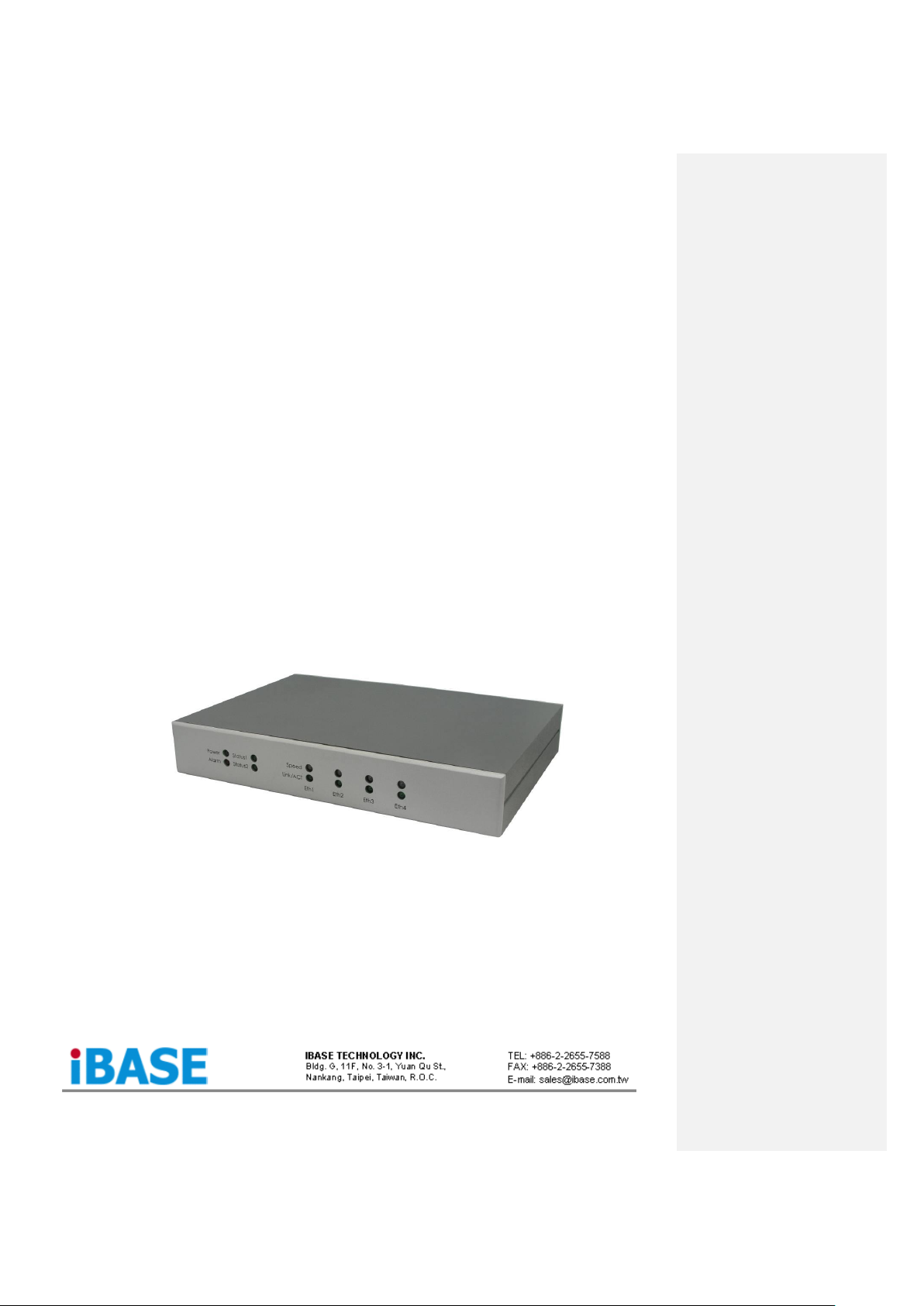
FWA7404 incorporates VIA VX900 chipset. Currently, the system is available in two models, namely:
Model
VIA NanoTM X2
Dual Core CPU
LAN Bypass
Watchdog Timer
FWA7404
1.2 GHz
Yes
Yes
FWA7404-NB
1.2 GHz
No
Yes
FWA7404 Features
Supports four Realtek 10/100/1000 LAN ports
Supports 1.2GHz VIA NanoTM X2 U4300 processor
DDR3 SO-DIMM x 1, up to 2GB
Mini PCI-e (USB Signal) slot, Compact Flash socket
Optional Hardware LAN Bypass function on Eth1 & 2
Specifications
Form Factor
Desktop / Table Top Networking Product
CPU
VIA NanoTM X2 U4300 Dual Core @ 1.2 GHz, 13W
x86 and x64 (64-bit) capability
Bus speeds up to 1066 MHz
Hardware Virtualization (VMX)
VIA Virtualization (VIA-VT)
Enhanced PowerSaver provides fastest performance state switching
Multi-processor support: Dual processing (SMP)
MMX, SSE, SSE2, SSSE3 and SSE4.1 compatible instructions
Two large (64-KB each, 16-way) Level 1 caches per core
1 MB Level 2 victim cache (32-way) with ECC per core (2 MB Total)
Two Large TLBs (196 entries each, 12-way)
Chipset
VIA VX900 FSB 400~800 MHz, 4.5W
1.2V Core Voltage
800 / 533 / 400 MHz FSB support
PCI-e Gen2
128 bit 2D Graphic Engine
Ethernet
controller
Onboard 4X Realtek RT8111E PCIe GbE with RJ45
Memory
Single channel DDR3 up to 1066MHz
SO-DIMM Socket x1
Network
4x Realtek RT8111E Gigabit LAN, optional Bypass
Network Bypass
Up to One segments hardware Bypass (ETH 1 & 2)
Control by GPIO / Watchdog / Electrical Disconnect (Power Off)
Watchdog Timer
Yes (256 segments, 0, 1, 2…255 sec/min)
Expansion Slot
Mini PCI-e Slot (USB Signal only)
Storage
Onboard CF Socket x1
Optional 2.5” SSD x1
LED Indicators
Power (Green) / Status (Green) / Alarm (Red)
LAN: Speed 10Mbps: LED off
100Mbps: Green
1000Mbps: Amber
Link / ACT: Green / Green Blinking
Rear Panel
DC +12V inlet
RJ45 x4
DB-9 Console Port
USB 2.0 x2
USB 2.0
2 ports
Page 6

FWA7404 Series User’s Manual
5
VGA
Pin header on board
Power
DC-In +12V, 40W
Dimensions
156 (W) x 225 (D) x 36 (H) mm
Chapter 3 Hardware Configuration
CPU board (IB831) layout
Jumper Setting
J3: Clear CMOS Setting
J3
Setting
Normal
Clear CMOS
Page 7

FWA7404 Series User’s Manual
6
JP3 & JP4: Bypass LANs & Reboot Setting
FAN1: CPU Fan Power Connector
FAN1 is a 4-pin header for the CPU fan. The fan must be 12V (Max. 1A).
Pin #
Signal Name
1
Ground
2
+12V
3
Rotation detection
4 Rotation control
FAN2: System Fan Power Connector
FAN2 is a 4-pin header for system fans. The fan must be 12V (Max. 1A).
Pin #
Signal Name
1
Ground
2
+12V
3
Rotation detection
4 Rotation control
CN3: USB1/2 Ports
S I G N A L
N A M E
Pin #
Pin #
Signal
Name
+5V
1 5 +5V
D-
2 6 D-
D+
3 7 D+
GND
4 8 GND
CN4, CN5: 10/100 /1000 RJ-45 Ports
S I G N A L
N A M E
Pin #
Pin #
TX+
1 2 TX-
RX+
3 4 NC
NC
5 6 RX-
NC
7 8 NC
Page 8

FWA7404 Series User’s Manual
7
CN6, CN7: 10/100 /1000 RJ-45 Ports
S I G N A L
N A M E
Pin #
Pin #
TX+
1 2 TX-
RX+
3 4 RX-
TCT
5 6 RCT
MDI2+
7 8 MDI2-
MDI3+
9
10
MDI3+
CN8: COM1 Serial Port
Pin #
Signal Name
1
DCD, Data carrier detect
2
RXD, Receive data
3
TXD, Transmit data
4
DTR, Data terminal ready
5
Ground
6
DSR, Data set ready
7
RTS, Request to send
8
CTS, Clear to send
9
RI, Ring indicator
SW1: System Reset
CN1: Serial ATA Port
J4: Parallel Port
Signal Name
Pin #
Pin #
Signal Name
STB-
1
14
AFD-
PD0
2
15
ERR-
PD1
3
16
INIT-
PD2
4
17
SLIN-
PD3
5
18
Ground
PD4
6
19
Ground
PD5
7
20
Ground
PD6
8
21
Ground
PD7
9
22
Ground
ACK-
10
23
Ground
BUSY
11
24
Ground
PE
12
25
Ground
SLCT
13
J5: LPC Debug Port
Signal Name
Pin #
Pin #
Signal Name
LAD0
1 2 LRESET
LAD1
3 4 LFRAME#
LAD2
5 6 +3.3V
LAD3
7 8 Ground
PCI_CLK1
9
J6: PS/2 Keyboard and PS/2 Mouse Connectors
Pin #
Signal Name
1
KBDA
2
KBCL
3
MDA
4
MCL
5
Ground
6
+5VSUS
Page 9

FWA7404 Series User’s Manual
8
J9: AT_12V Connector
J9 is a DC-in internal connector supporting +12V.
Pin #
Signal Name
1
+12V
2
Ground
J12: Mini PCI-E Connector (top side)
Pin Signal
Pin Signal
Pin Signal
1
WAKE#
19
RSVD4(UIM)
37
GND
2
+3.3Vaux
20
W_DISABLE
38
USB_D+
3
COEX1
21
GND
39
+3.3Vaux
4
GND
22
PERST#
40
GND
5
COEX2
23
PER_N0
41
+3.3Vaux
6
+1.5V
24
+3.3Vaux
42
LED_WWAN#
7
CLKREQ#
25
PER_P0
43
GND
8
UIM_PWR
26
GND
44
LED_WLAN#
9
GND
27
GND
45
RSVD9
10
UIM_DATA
28
+1.5V
46
LED_WPAN#
11
REFCLK-
29
GND
47
RSVD10
12
UIM_CLK
30
SMB_CLK
48
+1.5V
13
REFCLK+
31
PET_N0
49
RSVD11
14
UIM_RESET
32
SMB_DATA
50
GND
15
GND
33
PET_P0
51
RSVD12
16
UIM_CLK
34
GND
52
+3.3Vaux
17
RSVD3(UIM)
35
GND
18
GND
36
USB_D-
JP6: SPI Debug Port
S I G N A L
N A M E
Pin #
Pin #
2
NC
MSPISS0
3 4 SPIVCC
MSPIDI
5 6 -HOLD
-WP
7 8 MSPICLK
GND
9
10
MSPIDO
JP7: VGA Connector
S I G N A L
N A M E
Pin #
Pin #
DACR
1 2 +5VCRT
DACG
3 4 GND
DACB
5 6 NC
NC
7 8 CRT_SPD
GND
9
10
HSYNC_C
+5VCRT
11
12
VSYNC_C
GND
13
14
CRT_SPCL
K
GND
15
JP8: HDD Power Connector (Output: Max. 2A)
Pin #
Signal Name
1
+5V
2
Ground
3
Ground
4
+12V
Note: +12V power is provided with 2A maximum load.
Page 10

FWA7404 Series User’s Manual
9
CN2: Compact Flash Connector (top side)
Pin Signal
Pin Signal
Pin Signal
1
GND
18
A02
35
IOW#
2
D03
19
A01
36
WE# 3 D04
20
A00
37
INTRQ
4
D05
21
D00
38
VCC
5
D06
22
D01
39
CSEL#
6
D07
23
D02
40
NC/VS2
7
CS0#
24
IOCS16#
41
RESET#
8
GND/A10
25
CD2#
42
IORDY
9
ATA_SEL#
26
CD1#
43
NC/NPACK#
10
GND/A09
27
D11
44
VCC/REG
#
11
GND/A08
28
D12
45
DASP#
12
GND/A07
29
D13
46
PDIAG#
13
VCC
30
D14
47
D08
14
GND/A06
31
D15
48
D09
15
GND/A05
32
CS1#
49
D10
16
GND/A04
33
GND/VS1#
50
GND
17
GND/A03
34
IOR#
Chapter 4 Console Mode Information
FWA7404 supports output information via Console in BIOS level.
Prepare a computer as client loaded with an existing OS such Windows XP.
Connect client computer and FWA7404 with NULL Modem cable.
Follow the steps below to configure the Windows Hyper Terminal application setting:
1. For executing the Hyper Terminal, issue command “hypertrm”.
2. Customize your name for the new connection.
3. Choose the COM port on the client computer for the connection.
Page 11

FWA7404 Series User’s Manual
10
4. Please make the port settings to Baud rate 115200, Parity None, Data bits 8, Stop bits 1
5. Power up FWA7404 and the screen will display the BIOS information.
6. Press <Tab> key to enter BIOS setup screen in Console mode.
Press <Del> key to enter BIOS setup screen in VGA mode.
Page 12

FWA7404 Series User’s Manual
11
Chapter 5 Open the chassis
1.
Fig. 5-1 Loosen four screws on back to remove the
top lead. Keep the power cable locked on
rear panel.
Fig. 5-2 The top lead can be removed from the
base stand.
2.
Fig. 5-3 The base stand
Chapter 6 Removing and Installing CompactFlash Card
Fig. 6-1 Insert Compact Flash Card
Fig. 6-2 Push Compact Flash Card into the CF
interface
格式化: 項目符號及編號
格式化: 項目符號及編號
Page 13

FWA7404 Series User’s Manual
12
Chapter 7 Installing Memory Module
Fig. 7-1 Insert DDR3 SO-DIMM memory
module
Fig. 7-2 Push down the memory module into
socket
Chapter 8 Install 2.5” HDD
Fig. 8-1 Fasten four screws to lock HDD and
bracket together.
Fig. 8-2 Fasten the four stands-off to lock IB831.
Blue portion for long stands-off.
Red portion for short stands-off.
Page 14

FWA7404 Series User’s Manual
13
Fig. 8-3 Connect SATA & power cables on 2.5”
HDD
Fig. 8-4 Connect SATA & power cables on
IB831.
Fig. 8-5 Fix all four screws
Chapter 9 Lock Power Connector
Fig. 9-1 Plug power connector into power jack
 Loading...