

Page 1

ET860
Intel® AtomTM E3800 series SoC
COM-Express Module
USER’S MANUAL
Version 1.0
Page 2

Acknowledgments
AMI BIOS is a trademark of American Megatrends Inc.
PS/2 is a trademark of International Business Machines
Corporation.
Intel and Atom are registered trademarks of Intel Corporation.
Microsoft Windows is a registered trademark of Microsoft
Corporation.
Nuvoton is a registered trademark of Winbond Electronics
Corporation.
All other product names or trademarks are properties of their
respective owners.
.
ii
ET860 User’s Manual
Page 3
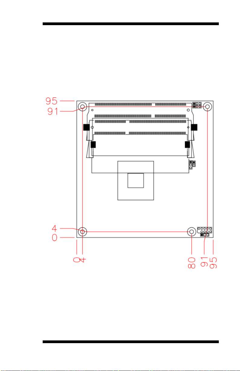
Table of Contents
Introduction .............................................................. 1
Product Description............................................................. 1
Checklist .............................................................................. 2
Specifications ...................................................................... 3
Board Dimensions for [ET860-I45/I27] .............................. 4
................................................................................... 4
Installations .............................................................. 5
Installing the Memory ......................................................... 6
Setting the Jumpers ............................................................. 7
Jumper & Connector Locations on ET860 ......................... 8
ET860 User’s Manual iii
Page 4
.... 8
iv
..... 8
JP1: Clear CMOS Contents ................................ .................. 9
JP2: Clear SRTC Register Contents ..................................... 9
JP3: SPI Flash connector (Factory use only)........................ 9
JP4: Micro SD Power .......................................................... 9
ET860 User’s Manual
Page 5

JP5: DVI or LVDS down to carrier board ........................... 9
DVI or LVDS Selection ................................ ....................... 9
CN1: Micro SD Connector .................................................. 9
BIOS Setup ............................................................. 10
BIOS Introduction ............................................................. 11
BIOS Setup ........................................................................ 11
Main Settings ..................................................................... 12
Advanced Settings ............................................................. 13
Chipset Settings ................................................................. 20
Security Settings ................................................................ 21
Boot Settings...................................................................... 22
Save & Exit Settings .......................................................... 23
Drivers Installation ................................................. 25
Intel Chipset Software Installation Utility ........................ 26
Intel Baytrail Graphics Driver Installation ........................ 27
Realtek High Definition Audio Driver Installation ........... 28
LAN Drivers Installation................................................... 29
Intel Trusted Execution Engine Installation...................... 30
Intel® USB 3.0 Drivers ..................................................... 31
SMSC WinUSB Driver Installation .................................. 32
Appendix ................................................................. 34
A. I/O Port Address Map .................................................. 34
B. Interrupt Request Lines (IRQ) ...................................... 36
C. Watchdog Timer Configuration ................................... 37
ET860 User’s Manual v
Page 6

This page is intentionally left blank.
vi
ET860 User’s Manual
Page 7

INTRODUCTION
Introduction
Product Description
The ET860 COM-Express Module is based on the latest Intel® Atom
E3800 series processors. It supports two DDR3L (1.35V) SODIMM
sockets for a maximum memory capacity of 8GB.
ET860 features the Intel® Gen7 with 4EUs graphics engines and has both
CRT and DisplayPort video display interface, and 24-bit LVDS dual
channel interface with the use of the NXP PTN3460 device.
The ET860 platform is well suited for low-power and high-performance
designs in a broad range of markets including Industrial Control &
Automation, Digital Signage, Thin Client, Electronic Gaming Machines,
and SMB storage appliances.
ET860F FEATURES:
Supports Atom
Two DDR3L SO-DIMM, 1066/1333 MHz, Max. 8GB memory
Intel® PCI-Express Gigabit LAN
Integrated Graphics for VGA/DisplayPort/LVDS displays
2x SATA 2.0, 4x USB 2.0, 1x USB 3.0
Micro SD
TM
E3800 series SoC processors
TM
ET860 User’s Manual 1
Page 8

INTRODUCTION
Checklist
Your ET860 package should include the items listed below.
The ET860 COM-Express Module
This User’s Manual
1 CD containing chipset drivers and flash memory utility
1 heat sink
2
ET860 User’s Manual
Page 9

Product Name
ET860-i45-LV (E3845 onboard w/LVDS)
ET860-i27-LV (E3827 onboard w/LVDS)
Form Factor
COM Express Type 6
SoC Type/Speed
- Intel® Atom
TM
QC E3845 (1.91GHz, 2MB cache, TDP=10W)
- Intel® AtomTM DC E3827 (1.75GHz, 1MB cache, TDP=8W)
FCBGA1170 , 22nm, 25mm x 27mm
BIOS
AMI BIOS
Memory
DDR3L-1333 (1.35V only)
SO-DIMM x2, Max. 8GB (Non-ECC), Dual-channel, horizontal type
VGA
Intel® Gen7 w/4EUs graphics engines(Gfx freq @ 542MHz/792MHz
[Turbo] )
Thru interface on carrier board for VGA, 1 x DDI #1,
DDI# 2 by switch for onboard LVDS or thru connector to carrier board
LVDS
- DP switch [NXP CBTL06DP213BS]
- Thru eDP to LVDS converter (NXP PTN3460) on board
- Jumper (3-pin type @ 2mm) for selecting PTN3460 or down to
carrier board)
LAN
Intel® I210IT GbE x 1
Thru interface on carrier board
USB
Intel® AtomTM SoC built-in USB host controller
USB 3.0 x 1 & USB 2.0 x 4
SMSC HSIC PHY USB4604I for USB 2.0 x 4
Serial ATA
Intel® AtomTM SoC built-in controller,
Supports 2 ports for SATA II (3Gb/sec.)
Audio
Intel® AtomTM SoC Built-in HD Audio controller with external HD
codec on carrier board
LPC I/O
Nuvoton NCT5523D (64-pin LQFP [7 mmx7 mm])
Connector
to Carrier Board
Two 220-pin connectors (A-B & C-D)
[COM Express 2.1 standard]
RTC
Intel® AtomTM SoC built-in RTC, battery on carrier board
Watch-DogTimer
Yes (256 segments, 0, 1, 2…255. sec/min) on carrier board
Power
+12V, +5VSB
Others
Heat spreader or Heatsink
Micro SD
OS Support
Windows 7, Windows 8, Linux
RoHS
Yes
Board Size
95mm x 95mm
Specifications
BIOS SETUP
ET860 User’s Manual 3
Page 10
BIOS SETUP
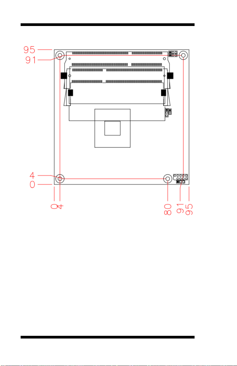
Board Dimensions for [ET860-I45/I27]
4
ET860 User’s Manual
Page 11

INSTALLATIONS
Installations
This section provides information on how to use the jumpers and
connectors on the ET860 in order to set up a workable system. The topics
covered are:
Installing the Memory ............................................................................ 6
Setting the Jumpers ................................................................................ 7
Connectors on ET860 ............................................................................ 8
ET860 User’s Manual 5
Page 12
INSTALLATIONS
DDR3 Module
Lock
Lock
Lock
Lock
Installing the Memory
The ET860 board supports two DDR3 memory socket for a maximum
total memory of 8GB in DDR3 SO-DIMM memory type.
Installing and Removing Memory Modules
To install the DDR3 modules, locate the memory slot on the board and
perform the following steps:
1. Hold the DDR3 module so that the key of the DDR3 module aligned
with that on the memory slot.
2. Gently push the DDR3 module in an upright position until the clips of
the slot close to hold the DDR3 module in place when the DDR3
module touches the bottom of the slot.
3. To remove the DDR3 module, press the clips with both hands.
6
ET860 User’s Manual
Page 13

INSTALLATIONS
Setting the Jumpers
Jumpers are used on ET860 to select various settings and features
according to your needs and applications. Contact your supplier if you
have doubts about the best configuration for your needs. The following
lists the connectors on ET860 and their respective functions.
Jumper & Connector Locations on ET860 ............................................ 8
JP1: Clear CMOS Contents ................................................................... 9
JP2: Clear SRTC Register Contents ...................................................... 9
JP3: SPI Flash connector (Factory use only) ......................................... 9
JP4: Micro SD Power ............................................................................ 9
JP5: DVI or LVDS down to carrier board ............................................. 9
ET860 User’s Manual 7
Page 14

INSTALLATIONS
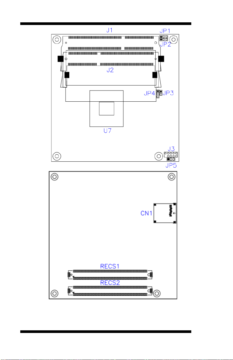
Jumper & Connector Locations on ET860
8
ET860 User’s Manual
Page 15
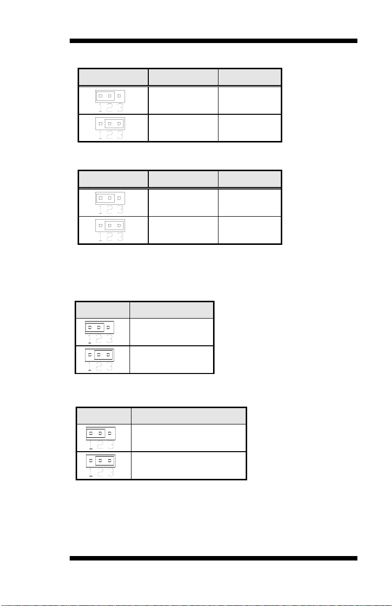
JP1
Setting
Function
Pin 1-2
Short/Closed
Normal
Pin 2-3
Short/Closed
Clear CMOS
JP2
Setting
Function
Pin 1-2
Short/Closed
Normal
Pin 2-3
Short/Closed
Clear
JP4
Micro SD Power
+3.3V (default)
+1.8V
JP5
DVI or LVDS Selection
DVI (default)
LVDS
JP1: Clear CMOS Contents
JP2: Clear SRTC Register Contents
[
JP3: SPI Flash connector (Factory use only)
JP4: Micro SD Power
JP5: DVI or LVDS down to carrier board
INSTALLATIONS
Note: JP5 supports ET860-I27 (w/o LVDS) module only.
CN1: Micro SD Connector
ET860 User’s Manual 9
Page 16

BIOS SETUP
BIOS Setup
This chapter describes the different settings available in the AMI BIOS
that comes with the board. The topics covered in this chapter are as
follows:
BIOS Introduction ................................................................................ 11
BIOS Setup .......................................................................................... 11
Main Settings ....................................................................................... 12
Advanced Settings ................................................................................ 13
Chipset Settings.................................................................................... 20
Security Settings .................................................................................. 21
Boot Settings ........................................................................................ 22
Save & Exit Settings ............................................................................ 23
10
ET860 User’s Manual
Page 17

BIOS SETUP
Warning:
It is strongly recommended that you avoid making any
changes to the chipset defaults. These defaults have been
carefully chosen by both AMI and your system manufacturer
to provide the absolute maximum performance and
reliability. Changing the defaults could cause the system to
become unstable and crash in some cases.
BIOS Introduction
The BIOS (Basic Input/Output System) installed in your computer
system’s ROM supports Intel processors. The BIOS provides critical
low-level support for a standard device such as disk drives, serial ports
and parallel ports. It also password protection as well as special support
for detailed fine-tuning of the chipset controlling the entire system.
BIOS Setup
The BIOS provides a Setup utility program for specifying the system
configurations and settings. The BIOS ROM of the system stores the
Setup utility. When you turn on the computer, the BIOS is immediately
activated. Pressing the <Del> key immediately allows you to enter the
Setup utility. If you are a little bit late pressing the <Del> key, POST
(Power On Self Test) will continue with its test routines, thus preventing
you from invoking the Setup. If you still wish to enter Setup, restart the
system by pressing the ”Reset” button or simultaneously pressing the
<Ctrl>, <Alt> and <Delete> keys. You can also restart by turning the
system Off and back On again. The following message will appear on the
screen:
Press <DEL> to Enter Setup
In general, you press the arrow keys to highlight items, <Enter> to select,
the <PgUp> and <PgDn> keys to change entries, <F1> for help and
<Esc> to quit.
When you enter the Setup utility, the Main Menu screen will appear on
the screen. The Main Menu allows you to select from various setup
functions and exit choices.
ET860 User’s Manual 11
Page 18

BIOS SETUP
Main Advanced Chipset Boot Security Save & Exit
BIOS Information
Choose the system default
language
→ ← Select Screen
↑↓ Select Item
Enter: Select
+- Change Field
F1: General Help
F2: Previous Values
F3: Optimized Default
F4: Save ESC: Exit
System Date
System Time
[Fri 11/14/2014]
[11:52:06]
Main Settings
Aptio Setup Utility – Copyright © 2013 American Megatrends, Inc.
System Date
Set the Date. Use Tab to switch between Data elements.
System Time
Set the Time. Use Tab to switch between Data elements.
12
ET860 User’s Manual
Page 19

BIOS SETUP
Main Advanced Chipset Boot Security Save & Exit
OnBoard LAN PXE ROM [Disabled]
► ACPI Settings
► LVDS (eDP/DP) Configuration
→ ← Select Screen
↑↓ Select Item
Enter: Select
+- Change Field
F1: General Help
F2: Previous Values
F3: Optimized Default
F4: Save ESC: Exit
► 1st Super IO Configuration
► 2nd Super IO Configuration
► 2nd Hardware Monitor
► S5 RTC Wake Settings
► CPU Configuration
► PPM Configuration
► IDE Configuration
► SDIO Configuration
► USB Configuration
Main Advanced Chipset Boot Security Save & Exit
ACPI Settings
→ ← Select Screen
↑↓ Select Item
Enter: Select
+- Change Field
F1: General Help
F2: Previous Values
F3: Optimized Default
F4: Save ESC: Exit
Enable ACPI Auto Configuration
Disabled
Enable Hibernation
Enabled
ACPI Sleep State
S3 (Suspend to RAM)
Advanced Settings
This section allows you to configure and improve your system and allows
you to set up some system features according to your preference.
Onboard LAN PXE ROM
Controls the execution of UEFI and Legacy PXE OpROM.
ACPI Settings
Aptio Setup Utility – Copyright © 2013 American Megatrends, Inc.
Aptio Setup Utility – Copyright © 2013 American Megatrends, Inc.
Enabled ACPI Auto Configuration
Enables or Disables BIOS ACPI Auto Configuration.
Enable Hibernation
Enables or Disables System ability to Hibernate (OS/S4 Sleep State).
This option may be not effective with some OS.
ACPI Sleep State
Select the highest ACPI sleep state the system will enter when the
SUSPEND button is pressed.
ET860 User’s Manual 13
Page 20

BIOS SETUP
Main Advanced Chipset Boot Security Save & Exit
LVDS (eDP/DP) Configuration
→ ← Select Screen
↑↓ Select Item
Enter: Select
+- Change Field
F1: General Help
F2: Previous Values
F3: Optimized Default
F4: Save ESC: Exit
LVDS (eDP/DP) Support
Panel Color Depth
Enabled
24 BIT
LVDS Channel Type
Panel Type
Single
1024 x 768
Main Advanced Chipset Boot Security Save & Exit
1st Super IO Configuration
→ ← Select Screen
↑↓ Select Item
Enter: Select
+- Change Field
F1: General Help
F2: Previous Values
F3: Optimized Default
F4: Save ESC: Exit
Super IO Chip
F81846
► Serial Port 1 Configuration
► Serial Port 2 Configuration
► Parallel Port Configuration
Main Advanced Chipset Boot Security Save & Exit
2nd Super IO Configuration
→ ← Select Screen
↑↓ Select Item
Enter: Select
+- Change Field
F1: General Help
F2: Previous Values
F3: Optimized Default
F4: Save ESC: Exit
Super IO Chip
NCT5523D
► Serial Port 3 Configuration
► Serial Port 4 Configuration
PWM Frequency
LVDS Brightness
11.6KHz
Level-7 (Max)
LVDS Configuration (For ET860-LV only)
Aptio Setup Utility – Copyright © 2013 American Megatrends, Inc.
1st Super IO Configuration
Aptio Setup Utility – Copyright © 2013 American Megatrends, Inc.
2nd Super IO Configuration
Aptio Setup Utility – Copyright © 2013 American Megatrends, Inc.
14
ET860 User’s Manual
Page 21

BIOS SETUP
Main Advanced Chipset Boot Security Save & Exit
PC Health Status
→ ← Select Screen
↑↓ Select Item
Enter: Select
+- Change Field
F1: General Help
F2: Previous Values
F3: Optimized Default
F4: Save ESC: Exit
System temperature
+29 C
CPU temperature
+31 C
VCORE
+0.840 V
1.35V
+1.360 V
Main Advanced Chipset Boot Security Save & Exit
Wake system from S5 Disabled
→ ← Select Screen
↑↓ Select Item
Enter: Select
+- Change Field
F1: General Help
F2: Previous Values
F3: Optimized Default
F4: Save ESC: Exit
2nd Hardware Monitor
Aptio Setup Utility – Copyright © 2013 American Megatrends, Inc.
Temperatures/Voltages
These fields are the parameters of the hardware monitoring function
feature of the motherboard. The values are read-only values as monitored
by the system and show the PC health status
S5 RTC Wake Settings
Aptio Setup Utility – Copyright © 2013 American Megatrends, Inc.
Wake system from S5
Enable or disable System wake on alarm event. Select FixedTime, system
will wake on the::min::sec specified. Select DynamicTime, System will
wake on the current time + Increase minute (s).
ET860 User’s Manual 15
Page 22

BIOS SETUP
Main Advanced Chipset Boot Security Save & Exit
CPU Configuration
►Socket 0 CPU Information
→ ← Select Screen
↑↓ Select Item
Enter: Select
+- Change Field
F1: General Help
F2: Previous Values
F3: Optimized Default
F4: Save ESC: Exit
CPU Speed
1751 MHz
64-bit
Supported
Main Advanced Chipset Boot Security Save & Exit
CPU PPM Configuration
→ ← Select Screen
↑↓ Select Item
Enter: Select
+- Change Field
F1: General Help
F2: Previous Values
F3: Optimized Default
F4: Save ESC: Exit
EIST
Enabled
CPU Configuration
Aptio Setup Utility – Copyright © 2013 American Megatrends, Inc.
Socket 0 CPU Information
Socket specific CPU Information.
PPM Configuration
Aptio Setup Utility – Copyright © 2013 American Megatrends, Inc.
EIST
Enable/Disable Intel SpeedStep.
16
ET860 User’s Manual
Page 23

Main Advanced Chipset Boot Security Save & Exit
IDE Configuration
→ ← Select Screen
↑↓ Select Item
Enter: Select
+- Change Field
F1: General Help
F2: Previous Values
F3: Optimized Default
F4: Save ESC: Exit
Serial-ATA (SATA)
SATA Speed Support
SATA ODD Port
Enabled
Gen2
No ODD
SATA Mode
AHCI Mode
Serial-ATA Port 0
Enabled
SATA Port0 HotPlug
Disabled
Serial-ATA Port 1
Enabled
SATA Port1 HotPlug
Disabled
SATA Port0
Not Present
SATA Port1
Not Present
IDE Configuration
Aptio Setup Utility – Copyright © 2013 American Megatrends, Inc.
Serial-ATA(SATA)
Enabled / Disabled Serial ATA
SATA Mode
Select IDE / AHCI Mode
Serail –ATA Port 0
Enabled / Disabled Serial ATA Port 0
SATA Port0 HotPlug
Enabled / Disabled SATA Port 0 HotPlug
Serail –ATA Port 1
Enabled / Disabled Serial ATA Port 1
SATA Port1 HotPlug
Enabled / Disabled SATA Port 1 HotPlug
ET860 User’s Manual 17
BIOS SETUP
Page 24

BIOS SETUP
Main Advanced Chipset Boot Security Save & Exit
SDIO Configuration
→ ← Select Screen
↑↓ Select Item
Enter: Select
+- Change Field
F1: General Help
F2: Previous Values
F3: Optimized Default
F4: Save ESC: Exit
SDIO Access Mode
Auto
Main Advanced Chipset Boot Security Save & Exit
USB Configuration
→ ← Select Screen
↑↓ Select Item
Enter: Select
+- Change Field
F1: General Help
F2: Previous Values
F3: Optimized Default
F4: Save ESC: Exit
USB Module Version
8.11.03
USB Devices:
1 Hub
Legacy USB Support
Enabled
XHCI Hand-off
Enabled
EHCI Hand-off
Enabled
USB Mass Storage Driver Support
Enabled
USB hardware delays and time-outs:
USB Transfer time-out
20 sec
Device reset time-out
20 sec
Device power-up delay
Auto
SDIO Configuration
Aptio Setup Utility – Copyright © 2013 American Megatrends, Inc.
SDIO Access Mode
Auto Option: Access SD device in DMA mode if controller supports it,
otherwise in PIO mode.
DMA Option: Access SD device in DMA mode.
PIO Option: Access PIO device in PIO mode.
USB Configuration
Aptio Setup Utility – Copyright © 2013 American Megatrends, Inc.
Legacy USB Support
Enables Legacy USB support.
AUTO option disables legacy support if no USB devices are connected.
DISABLE option will keep USB devices available only for EFI
applications.
18
ET860 User’s Manual
Page 25

BIOS SETUP
XHCI Hand-off
This is a workaround for OSes without XHCI hand-off support. The
XHCI ownership change should be claimed by XHCI driver.
EHCI Hand-off
This is a workaround for OSes without EHCI hand-off support. The
EHCI ownership change should be claimed by EHCI driver.
USB Mass Storage Driver Support
Enable/Disable USB Mass Storage Driver Support.
USB Transfer time-out
The time-out value for Control, Bulk, and Interrupt transfers.
Device reset time-out
USB mass storage device start Unit command time-out.
Device power-up delay
Maximum time the device will take before it properly reports itself to the
Host Controller. ‘Auto’ uses default value: for a Root port it is 100ms, for
a Hub port the delay is taken from Hub descriptor.
ET860 User’s Manual 19
Page 26

BIOS SETUP
Main Advanced Chipset Boot Security Save & Exit
→ ← Select Screen
↑↓ Select Item
Enter: Select
+- Change Field
F1: General Help
F2: Previous Values
F3: Optimized Default
F4: Save ESC: Exit
► North Bridge
► South Bridge
Main Advanced Chipset Boot Security Save & Exit
→ ← Select Screen
↑↓ Select Item
Enter: Select
+- Change Field
F1: General Help
F2: Previous Values
F3: Optimized Default
F4: Save ESC: Exit
Memory Information
Total Memory
4096 MB (LPDDR3)
Memory Slot0
4096 MB (LPDDR3)
Memory Slot2
Not Present
Main Advanced Chipset Boot Security Save & Exit
→ ← Select Screen
↑↓ Select Item
Enter: Select
+- Change Field
F1: General Help
F2: Previous Values
F3: Optimized Default
F4: Save ESC: Exit
XHCI mode
Auto
Restore AC Power Loss
Power Off
Chipset Settings
This section allows you to configure and improve your system and allows
you to set up some system features according to your preference.
North Bridge
Aptio Setup Utility – Copyright © 2013 American Megatrends, Inc.
Aptio Setup Utility – Copyright © 2013 American Megatrends, Inc.
South Bridge
Aptio Setup Utility – Copyright © 2013 American Megatrends, Inc.
XHCI mode
Mode of operation of XHCI controller.
Restore AC Power Loss
Select AC power state when power is re-applied after a power failure.
20
ET860 User’s Manual
Page 27

BIOS SETUP
Main Advanced Chipset Boot Security Save & Exit
Password Description
→ ← Select Screen
↑↓ Select Item
Enter: Select
+- Change Field
F1: General Help
F2: Previous Values
F3: Optimized Default
F4: Save ESC: Exit
If ONLY the Administrator’s password is set, then
this only limit access to Setup and is only asked
for when entering Setup.
If ONLY the User’s password is set, then this is a
power on password and must be entered to boot
or enter Setup. In Setup the User will have
Administrator rights
The password length must be
in the following range:
Minimum length
3
Maximum length
20
Administrator Password
Security Settings
This section allows you to configure and improve your system and allows
you to set up some system features according to your preference.
Administrator Password
Set Administrator Password.
Aptio Setup Utility – Copyright © 2013 American Megatrends, Inc.
ET860 User’s Manual 21
Page 28

BIOS SETUP
Main Advanced Chipset Boot Security Save & Exit
Boot Configuration
→ ← Select Screen
↑↓ Select Item
Enter: Select
+- Change Field
F1: General Help
F2: Previous Values
F3: Optimized Default
F4: Save ESC: Exit
Setup Prompt Timeout
1
Bootup NumLock State
On
Quiet Boot
Disabled
Fast Boot
Disabled
Boot mode select
LEGACY
FIXED BOOT ORDER Priorities
Boot Option # 1
Hard Disk
Boot Option # 2
CD/DVD
Boot Option # 3
USB Hard Disk
Boot Option # 4
USB CD/DVD
Boot Option # 5
USB Key
Boot Option # 6
USB Floppy
Boot Option # 7
USB Lan
Boot Option # 8
Network
Boot Settings
This section allows you to configure the boot settings.
Setup Prompt Timeout
Number of seconds to wait for setup activation key.
65535(0xFFFF) means indefinite waiting.
Bootup NumLock State
Select the keyboard NumLock state.
Quiet Boot
Enables or disables Quiet Boot option.
Fast Boot
Enables or disables boot with initialization of a minimal set of devices
required to launch active boot option. Has no effect for BBS boot
options.
Boot mode select
Select boot mode LEGACY/UEFI.
22
Aptio Setup Utility – Copyright © 2013 American Megatrends, Inc.
ET860 User’s Manual
Page 29

Main Advanced Chipset Boot Security Save & Exit
Save Changes and Exit
→ ← Select Screen
↑↓ Select Item
Enter: Select
+- Change Field
F1: General Help
F2: Previous Values
F3: Optimized Default
F4: Save ESC: Exit
Discard Changes and Exit
Save Changes and Reset
Discard Changes and Reset
Save Options
Save Changes
Discard Changes
Restore Defaults
Save as User Defaults
Restore User Defaults
Boot Override
Save & Exit Settings
Aptio Setup Utility – Copyright © 2013 American Megatrends, Inc.
Save Changes and Exit
Exit system setup after saving the changes.
Discard Changes and Exit
Exit system setup without saving any changes.
Save Changes and Reset
Reset the system after saving the changes.
Discard Changes and Reset
Reset system setup without saving any changes.
Save Changes
Save Changes done so far to any of the setup options.
Discard Changes
Discard Changes done so far to any of the setup options.
Restore Defaults
Restore/Load Defaults values for all the setup options.
Save as User Defaults
Save the changes done so far as User Defaults.
Restore User Defaults
Restore the User Defaults to all the setup options.
ET860 User’s Manual 23
BIOS SETUP
Page 30

BIOS SETUP
This page is intentionally left blank.
24
ET860 User’s Manual
Page 31

DRIVERS INSTALLATION
Drivers Installation
This section describes the installation procedures for software and
drivers. The software and drivers are included with the motherboard. If
you find the items missing, please contact the vendor where you made the
purchase. The contents of this section include the following:
Intel Chipset Software Installation Utility ........................................... 26
Intel Baytrail Graphics Driver Installation ........................................... 27
Realtek High Definition Audio Driver Installation .............................. 28
LAN Drivers Installation ..................................................................... 29
Intel TXE Drivers Installation ............................................................. 30
Intel USB 3.0 Drivers ................................................................ 31
SMSC WinUSB Driver Installation ........................................... 32
IMPORTANT NOTE:
After installing your Windows operating system, you must install first the
Intel Chipset Software Installation Utility before proceeding with the
drivers installation.
ET860 User’s Manual 25
Page 32

DRIVER INSTALLATION
Intel Chipset Software Installation Utility
The Intel Chipset Drivers should be installed first before the software
drivers to enable Plug & Play INF support for Intel chipset components.
Follow the instructions below to complete the installation.
1. Insert the DVD that comes with the board. Click Intel and then
Intel(R) Baytrail Chipset Drivers. Click Intel(R) Chipset Software
Installation Utility.
2. When the Welcome screen to the Intel Chipset Device Software
appears, click Next to continue.
3. Click Yes to accept the software license agreement and proceed with
the installation process. Click Next to continue.
4. The Setup process is now complete. Click Finish to restart the
computer and for changes to take effect.
26
ET860 User’s Manual
Page 33

DRIVERS INSTALLATION
Intel Baytrail Graphics Driver Installation
1. Insert the DVD that comes with the board. Click Intel and then
Intel(R) Baytrail Chipset Drivers. Click Intel(R) Baytrail Graphics
Driver.
2. When the Welcome screen appears, click Next to continue.
3. Click Yes to accept the license agreement and continue the installation.
Click Next to continue.
4. Setup complete. Click Finish to restart the computer and for changes
to take effect.
ET860 User’s Manual 27
Page 34

DRIVER INSTALLATION
Realtek High Definition Audio Driver
Installation
1. Insert the DVD that comes with the board. Click Intel and then
Intel(R) Baytrail Chipset. Click Realtek High Definition Audio Driver.
2. On the Welcome screen, click Next to proceed with the installation.
3. InstallShield Wizard is complete. Click Finish to restart the computer
and for changes to take effect.
28
ET860 User’s Manual
Page 35

DRIVERS INSTALLATION
LAN Drivers Installation
1. Insert the DVD that comes with the board. Click LAN Card and then
click Intel LAN Controller Drivers. Click Intel(R) I21x Gigabit
Network Drivers.
2. When the Welcome screen appears, click Next to continue.
3. Click Next to to agree with the license agreement.
4. When the Setup Options screen appears, click Next to continue.
5. The wizard is ready to begin installation. Click Install to begin the
installation.
6. When InstallShield Wizard is complete, click Finish.
ET860 User’s Manual 29
Page 36

DRIVER INSTALLATION
Intel Trusted Execution Engine Installation
Note :Windows 7 OS only
1. Insert the DVD that comes with the board. Click Intel and then
Intel(R) Baytrail Chipset. Click Intel(R) TXE Drivers.
2. On the Setup Welcome screen, click Next to proceed with the
installation process.
3. Click Next accept the license agreement and continue the installation,
click Next to continue.
4. Installation of the Intel Trusted Execution Engine is now complete.
Click Finish to restart the computer and for changes to take effect.
30
ET860 User’s Manual
Page 37

DRIVERS INSTALLATION
Intel® USB 3.0 Drivers
1. Insert the DVD that comes with the board. Click Intel and then
Intel(R) Baytrail Chipset. Click Intel(R) USB 3.0 Drivers.
2. When the Welcome screen to the InstallShield Wizard for Intel® USB
3.0 eXtensible Host Controller Driver, click Next.
3. Click Yes to to agree with the license agreement and continue the
installation.
4. On the Readme File Information screen, click Next to continue the
installation of the Intel® USB 3.0 eXtensible Host Controller Driver.
5. When the Setup Progress screen appears, click Next. Setup complete.
Click Finish to restart the computer and for changes to take effect.
ET860 User’s Manual 31
Page 38

DRIVER INSTALLATION
SMSC WinUSB Driver Installation
1. In the Windows operating system, go to the Device Manager.
2. As shown below, click the Bridge Device under Other devices.
3. In the following window, click the Update Driver and click OK to
continue.
32
ET860 User’s Manual
Page 39

DRIVERS INSTALLATION
4. When the Update Driver Software – Bridge device screen appears,
click Browse my computer for driver software.
5. Click Browse to find the driver’s path in the DVD provided –
Intel\Baytrail\HSIC. Then click Next to start the drivers installtion.
Click Install to continue.
6. Then click Finish for changes to take effect.
ET860 User’s Manual 33
Page 40

APPENDIX
Address
Device Description
0000h - 006Fh
PCI bus
0020h - 0021h
Programmable interrupt controller
0024h - 0025h
Programmable interrupt controller
0028h - 0029h
Programmable interrupt controller
002Ch - 002Dh
Programmable interrupt controller
0030h - 0031h
Programmable interrupt controller
0034h - 0035h
Programmable interrupt controller
0038h - 0039h
Programmable interrupt controller
003Ch - 003Dh
Programmable interrupt controller
0040h - 0043h
System timer
0050h - 0053h
System timer
0060h - 0060h
Standard PS/2 Keyboard
0064h - 0064h
Standard PS/2 Keyboard
0070h - 0070h
System CMOS/real time clock
0078h - 0CF7h
PCI bus
00A0h - 00A1h
Programmable interrupt controller
00A4h - 00A5h
Programmable interrupt controller
00A8h - 00A9h
Programmable interrupt controller
00ACh - 00ADh
Programmable interrupt controller
00B0h - 00B1h
Programmable interrupt controller
00B4h - 00B5h
Programmable interrupt controller
00B8h - 00B9h
Programmable interrupt controller
00BCh - 00BDh
Programmable interrupt controller
0240h - 0247h
Communications Port (COM3)
0250h - 0257h
Communications Port (COM4)
02F8h - 02FFh
Communications Port (COM2)
0378h - 037Fh
Printer Port (LPT1)
Appendix
A. I/O Port Address Map
Each peripheral device in the system is assigned a set of I/O port
addresses which also becomes the identity of the device. The following
table lists the I/O port addresses used.
34
ET860 User’s Manual
Page 41

APPENDIX
Address
Device Description
03B0h - 03BBh
Intel(R) Atom(TM) Processor E3800
Series/Intel(R) Celeron(R) Processor
N2920/J1900
03C0h - 03DFh
Intel(R) Atom(TM) Processor E3800
Series/Intel(R) Celeron(R) Processor
N2920/J1900
03F8h - 03FFh
Communications Port (COM1)
04D0h - 04D1h
Programmable interrupt controller
0D00h - FFFFh
PCI bus
C000h - CFFFh
Intel(R) Pentium(R) processor N- and J-series /
Intel(R) Celeron(R) processor N- and J-series PCI
Express - Root Port 2 - 0F4A
D000h - DFFFh
Intel(R) Pentium(R) processor N- and J-series /
Intel(R) Celeron(R) processor N- and J-series PCI
Express - Root Port 1 - 0F48
E000h - E01Fh
Intel(R) Pentium(R) processor N- and J-series /
Intel(R) Celeron(R) processor N- and J-series
Platform Control Unit - SMBus Port - 0F12
E020h - E03Fh
Intel(R) Pentium(R) processor N- and J-series /
Intel(R) Celeron(R) processor N- and J-series
AHCI - 0F23
E040h - E043h
Intel(R) Pentium(R) processor N- and J-series /
Intel(R) Celeron(R) processor N- and J-series
AHCI - 0F23
E050h - E057h
Intel(R) Pentium(R) processor N- and J-series /
Intel(R) Celeron(R) processor N- and J-series
AHCI - 0F23
E060h - E063h
Intel(R) Pentium(R) processor N- and J-series /
Intel(R) Celeron(R) processor N- and J-series
AHCI - 0F23
E070h - E077h
Intel(R) Pentium(R) processor N- and J-series /
Intel(R) Celeron(R) processor N- and J-series
AHCI - 0F23
E080h - E087h
Intel(R) Atom(TM) Processor E3800
Series/Intel(R) Celeron(R) Processor
N2920/J1900
ET860 User’s Manual 35
Page 42

APPENDIX
Level
Function
IRQ 0
System timer
IRQ 1
Standard PS/2 Keyboard
IRQ 3
Communications Port (COM2)
IRQ 4
Communications Port (COM1)
IRQ 5
Intel(R) Pentium(R) processor N- and J-series /
Intel(R) Celeron(R) processor N- and J-series
Platform Control Unit - SMBus Port - 0F12
IRQ 8
High precision event timer
IRQ 11
Communications Port (COM3)
IRQ 11
Communications Port (COM4)
IRQ 16
Intel(R) Pentium(R) processor N- and J-series /
Intel(R) Celeron(R) processor N- and J-series PCI
Express - Root Port 1 - 0F48
IRQ 17
Intel(R) Pentium(R) processor N- and J-series /
Intel(R) Celeron(R) processor N- and J-series PCI
Express - Root Port 2 - 0F4A
IRQ 18
SDA Standard Compliant SD Host Controller
IRQ 18
Intel(R) Pentium(R) processor N- and J-series /
Intel(R) Celeron(R) processor N- and J-series PCI
Express - Root Port 3 - 0F4C
IRQ 19
Intel(R) Pentium(R) processor N- and J-series /
Intel(R) Celeron(R) processor N- and J-series PCI
Express - Root Port 4 - 0F4E
IRQ 19
Intel(R) Pentium(R) processor N- and J-series /
Intel(R) Celeron(R) processor N- and J-series AHCI
- 0F23
IRQ 22
High Definition Audio Controller
B. Interrupt Request Lines (IRQ)
Peripheral devices use interrupt request lines to notify CPU for the
service required. The following table shows the IRQ used by the devices
on board.
36
ET860 User’s Manual
Page 43

APPENDIX
C. Watchdog Timer Configuration
The WDT is used to generate a variety of output signals after a user
programmable count. The WDT is suitable for use in the prevention of
system lock-up, such as when software becomes trapped in a deadlock.
Under these sorts of circumstances, the timer will count to zero and the
selected outputs will be driven. Under normal circumstance, the user will
restart the WDT at regular intervals before the timer counts to zero.
SAMPLE CODE:
File of the NCT5523D.H
//--------------------------------------------------------------------------//
// THIS CODE AND INFORMATION IS PROVIDED "AS IS" WITHOUT WARRANTY OF ANY
// KIND, EITHER EXPRESSED OR IMPLIED, INCLUDING BUT NOT LIMITED TO THE
// IMPLIED WARRANTIES OF MERCHANTABILITY AND/OR FITNESS FOR A PARTICULAR
// PURPOSE.
//
//--------------------------------------------------------------------------#ifndef __NCT5523D_H
#define __NCT5523D_H 1
//--------------------------------------------------------------------------#define NCT5523D_INDEX_PORT (NCT5523D_BASE)
#define NCT5523D_DATA_PORT (NCT5523D_BASE+1)
//--------------------------------------------------------------------------#define NCT5523D_REG_LD 0x07
//--------------------------------------------------------------------------#define NCT5523D_UNLOCK 0x87
#define NCT5523D_LOCK 0xAA
//--------------------------------------------------------------------------unsigned int Init_NCT5523D(void);
void Set_NCT5523D_LD( unsigned char);
void Set_NCT5523D_Reg( unsigned char, unsigned char);
unsigned char Get_NCT5523D_Reg( unsigned char);
//--------------------------------------------------------------------------#endif //__NCT5523D_H
ET860 User’s Manual 37
Page 44

APPENDIX
File of the MAIN.CPP.
//--------------------------------------------------------------------------//
// THIS CODE AND INFORMATION IS PROVIDED "AS IS" WITHOUT WARRANTY OF ANY
// KIND, EITHER EXPRESSED OR IMPLIED, INCLUDING BUT NOT LIMITED TO THE
// IMPLIED WARRANTIES OF MERCHANTABILITY AND/OR FITNESS FOR A PARTICULAR
// PURPOSE.
//
//--------------------------------------------------------------------------#include <dos.h>
#include <conio.h>
#include <stdio.h>
#include <stdlib.h>
#include "NCT5523D.H"
//--------------------------------------------------------------------------int main (void);
void WDTInitial(void);
void WDTEnable(unsigned char);
void WDTDisable(void);
//--------------------------------------------------------------------------int main (void)
{
char SIO;
SIO = Init_NCT5523D();
if (SIO == 0)
{
printf("Can not detect Nuvoton NCT5523D, program abort.\n");
return(1);
}
WDTInitial();
WDTEnable(10);
WDTDisable();
return 0;
}
//--------------------------------------------------------------------------void WDTInitial(void)
{
unsigned char bBuf;
Set_NCT5523D_LD(0x08); //switch to logic device 8
bBuf = Get_NCT5523D_Reg(0x30);
bBuf &= (~0x01);
Set_NCT5523D_Reg(0x30, bBuf); //Enable WDTO
}
//---------------------------------------------------------------------------
38
ET860 User’s Manual
Page 45

APPENDIX
void WDTEnable(unsigned char NewInterval)
{
unsigned char bBuf;
Set_NCT5523D_LD(0x08); //switch to logic device 8
Set_NCT5523D_Reg(0x30, 0x01); //enable timer
bBuf = Get_NCT5523D_Reg(0xF0);
bBuf &= (~0x08);
Set_NCT5523D_Reg(0xF0, bBuf); //count mode is second
Set_NCT5523D_Reg(0xF1, NewInterval); //set timer
}
//--------------------------------------------------------------------------void WDTDisable(void)
{
Set_NCT5523D_LD(0x08); //switch to logic device 8
Set_NCT5523D_Reg(0xF1, 0x00); //clear watchdog timer
Set_NCT5523D_Reg(0x30, 0x00); //watchdog disabled
}
//---------------------------------------------------------------------------
ET860 User’s Manual 39
Page 46

APPENDIX
File of the NCT5523D.CPP
//--------------------------------------------------------------------------//
// THIS CODE AND INFORMATION IS PROVIDED "AS IS" WITHOUT WARRANTY OF ANY
// KIND, EITHER EXPRESSED OR IMPLIED, INCLUDING BUT NOT LIMITED TO THE
// IMPLIED WARRANTIES OF MERCHANTABILITY AND/OR FITNESS FOR A PARTICULAR
// PURPOSE.
//
//--------------------------------------------------------------------------#include "NCT5523D.H"
#include <dos.h>
//--------------------------------------------------------------------------unsigned int NCT5523D_BASE;
void Unlock_NCT5523D (void);
void Lock_NCT5523D (void);
//--------------------------------------------------------------------------unsigned int Init_NCT5523D(void)
{
unsigned int result;
unsigned char ucDid;
NCT5523D_BASE = 0x4E;
result = NCT5523D_BASE;
ucDid = Get_NCT5523D_Reg(0x20);
if (ucDid == 0xC4) //NCT5523D??
{ goto Init_Finish; }
NCT5523D_BASE = 0x2E;
result = NCT5523D_BASE;
ucDid = Get_NCT5523D_Reg(0x20);
if (ucDid == 0xC4) //NCT5523D??
{ goto Init_Finish; }
NCT5523D_BASE = 0x00;
result = NCT5523D_BASE;
Init_Finish:
return (result);
}
//--------------------------------------------------------------------------void Unlock_NCT5523D (void)
{
outportb(NCT5523D_INDEX_PORT, NCT5523D_UNLOCK);
outportb(NCT5523D_INDEX_PORT, NCT5523D_UNLOCK);
}
//--------------------------------------------------------------------------void Lock_NCT5523D (void)
{
outportb(NCT5523D_INDEX_PORT, NCT5523D_LOCK);
}
//---------------------------------------------------------------------------
40
ET860 User’s Manual
Page 47

void Set_NCT5523D_LD( unsigned char LD)
{
Unlock_NCT5523D();
outportb(NCT5523D_INDEX_PORT, NCT5523D_REG_LD);
outportb(NCT5523D_DATA_PORT, LD);
Lock_NCT5523D();
}
//--------------------------------------------------------------------------void Set_NCT5523D_Reg( unsigned char REG, unsigned char DATA)
{
Unlock_NCT5523D();
outportb(NCT5523D_INDEX_PORT, REG);
outportb(NCT5523D_DATA_PORT, DATA);
Lock_NCT5523D();
}
//--------------------------------------------------------------------------unsigned char Get_NCT5523D_Reg(unsigned char REG)
{
unsigned char Result;
Unlock_NCT5523D();
outportb(NCT5523D_INDEX_PORT, REG);
Result = inportb(NCT5523D_DATA_PORT);
Lock_NCT5523D();
return Result;
}
//-----------------------------------------------------------------------
APPENDIX
ET860 User’s Manual 41
 Loading...