

Page 1
CSB200-888
User Manual
2009 October V1.0
Page 2

Copyright © 2008 IBASE Technology INC. All Rights Reserved.
No part of this manual, including the products and software described in it, may be
reproduced, transmitted, transcribed, stored in a retrieval system, or translated into
any language in any form or by any means, except documentation kept by the
purchaser for backup purposes, without the express written permission of IBASE
Technology INC. (“IBASE”).
Products and corporate names mentioned in this manual may or may not be
registered trademarks or copyrights of their respective companies, and are used for
identification purposes only. All trademarks are the property of their respective
owners.
Every effort has been made to ensure that the contents of this manual are c orrect and
up to date. However, the manufacturer makes no guarantee regarding the accuracy of
its contents, and reserves the right to make changes without prior notice.
2
Page 3

Table of Contents
Accessories ........................................................................................................... 6
Components .......................................................................................................... 7
Front V iew ................................................................................................................... 7
Rear View .................................................................................................................... 8
Specification ........................................................................................................ 10
Mounting CSB200-888 to VESA mounting bracket ................................................. 11
Mounting procedure: ................................................................................................. 11
Exploded view of the CSB200-888 assembly .......................................................... 12
Parts description ........................................................................................................ 12
Driver Installation ................................................................................................ 13
BIOS Setup ........................................................................................................... 13
3
Page 4

Safety Information
Your CSB200-888 is designed and tested to meet the latest standards of safety for
information technology equipment. However, to ensure your safety, it is important that
you read the following safety instructions.
Setting up your system
• Read and follow all instructions in the documentation before you operate your
system.
• Do not use this product near water.
• Set up the system on a stable surface or secure on wall with the provided rail. Do
not secure the system on any unstable plane or wi thout the rail.
• Do not place this product on an unstable cart, stand, or table. The product may
fall, causing serious damage to the product.
• Slots and openings on the chassis are for ventilation. Do not block or cover these
openings. Make sure you leave plenty of space ar ound the system for ventilation.
Never insert objects of any kind into the ventilation openings.
• This system should be operated from the type of power indicated on the marking
label. If you are not sure of the type of power available, consult your dealer or
local power company.
• Use this product in environments with ambient temperatures between 0˚C and
45˚C.
• If you use an extension cord, make sure that the total ampere rating of the
devices plugged into the extension cord does not exceed its ampere rating.
Care during use
• Do not walk on the power cord or allow anything to rest on it.
• Do not spill water or any other liquids on your system.
• When the system is turned off, a small amount of electrical current still flows.
Always unplug all power, and network cables from the power outlets before
cleaning the system.
• If you encounter the following technical problems with the product, unplug the
power cord and contact a qualified service technician or your retailer.
The power cord or plug is damaged.
Liquid has been spilled into the system.
The system does not function properly even if you follow the operating
instructions.
4
Page 5

The system was dropped or the cabinet is damaged.
Lithium-Ion Battery Warning
CAUTION: Danger of explosion if batter y is incorrectly replaced. Replace only with
the same or equivalent type recommended by the manufacturer. Dispose of used
batteries according to the manufacturer’s instructions.
NO DISASSEMBLY
The warranty does not apply to the products that have been disassembled by users
5
Page 6

Accessories
a. Power Cord x 1 b. M/B Manual x 1
c. Driver CD x 1 d. Power Brick x 1
e. Mounting Rail Screw x 4 f. Mounting Bracket x 1
6
Page 7

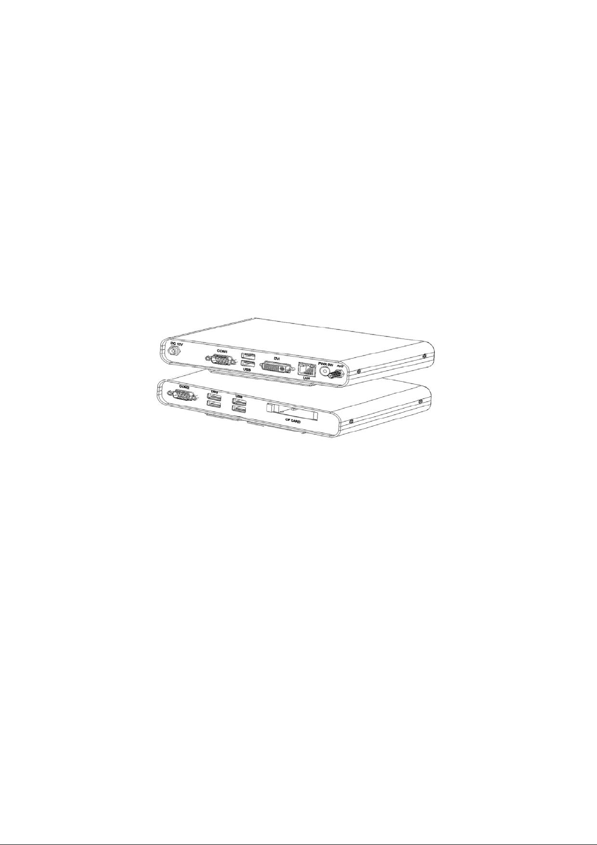
Components
Front View
Refer to the diagram below to identify the components on this side of the system.
COM2
Communication or serial port one is compatible with RS-232 interface.
USB
The USB (Universal Serial Bus) port is compatible with USB devices such as
keyboards, mouse devices, cameras, and hard disk drives. USB allows many
devices to run simultaneously on a single computer, with some peripheral acting
as additional plug-in sites or hubs.
CF CARD
Compact-Flash card slot supports up to Type-II specification.
7
Page 8

Rear View
Refer to the diagram below to identify the components on this side of the system.
DC 12V
The supplied power adapter converts AC power to DC power for use with this
jack. Power supplied through this jack supplies power to the system. To prevent
damage to the system, always use the supplied power adapter.
COM1
Communication or serial port one is compatible with RS-232 interface.
VGA
Video Graphic Array (VGA) port supports a VGA-compatible device such as a
monitor or projector. The system default display output port.
USB
The USB (Universal Serial Bus) port is compatible with USB devices such as
keyboards, mouse devices, cameras, and hard disk drives. USB allows many
devices to run simultaneously on a single computer, with some peripheral acting as
additional plug-in sites or hubs.
DVI
The Digital Visual Interface (DVI) port supports a high quality VGA-compatible
device such as a monitor or projector to allow viewing on a larger external
display.
LAN
The eight-pin RJ-45 LAN port supports a standard Ethernet cable for connection
to a local network.
8
Page 9

PWR SW
The power switch allows powering ON and OFF the system. T he backlight of the
power switch illuminated when system been power on.
ANT
The jack is reserve for connect the wireless antenna to enhance wireless signal
reception.
9
Page 10

Specification
System Mainboard IB888
Construction Steel
Chassis Color Black
Storage One CF type II socket
Mounting Desktop or wall mount
Dimensions 190mm(W) x 132mm(D) x 30mm(H)
(7.48” x 5.19” x 1.18”)
Power Supply 60W DC adapter
Operating
Temperature
Storage
Temperature
Relative Humidity 5~95% @45°C (non-condensing)
Vibration 0.25 grms/5~500Hz random operating
RoHS Available
0°C ~ 45°C (32°F ~ 113°F)
-20°C ~ 80°C
1 grms/5~500Hz random n o n -operating
‧This specification is subject to change without prior notice.
10
Page 11

Mounting CSB200-888 to VESA mounting bracket
Using attached mounting bracket, you can install CSB200 on standard 75x75mm
VESA mounting devices. Ensure the installer uses at least four M4 length 6mm
maximum screws to secure the system on VESA mounting device.
Fasteners are not included with the unit, and must be supplied by the installer. The
types of fasteners required are dependent on the type of device construction. To
assure proper fastener selection and installation, follow the fastener manufacturer’s
recommendations.
Mounting procedure:
- Using four embedded M3 flat head screws to secure the mounting
bracket on bottom of CSB200-888.
- Place CSB200-888 with mounting bracket on VESA75 device noting the
alignment, and then secure the system with four M4 screws.
11
Page 12

Exploded view of the CSB200-888 assembly
2
4
5
3
1
6
9
7
8
10
Parts description
Part NO. Description Part NO. Description
1 Base Chassis 2 Top Cover
3 Rear IO Panel 4 Front IO Panel
5 Mounting Bracket 6 Power But t on Bracket
7 IB888 8 CF Bracket
9 ID112 x 2 10 COM Port Extension
12
Page 13

Driver Installation
Please refer correspond mainboard user manual to install the driver properly.
BIOS Setup
Please refer correspond mainboard user manual to configure BIOS setting.
13
 Loading...