

Page 1
AMS100-807 Series
Version 1.0
Fanless System
Users Manual
Page 2

1
Table of Contents
Chapter 1 Specifications .................................................................................................................. 3
Chapter 2 AMS100-807 Series Features.......................................................................................... 4
Chapter 3 System Dimensions ......................................................................................................... 5
Chapter 4 Opening the Chassis ....................................................................................................... 6
Chapter 5 Installing the Memory Module .......................................................................................... 6
Chapter 6 Installing the 2.5” HDD..................................................................................................... 7
Chapter 7 Installing the Mini PCI-e Module ...................................................................................... 8
Chapter 8 Terminal Block (TB) DC Input .......................................................................................... 8
Chapter 9 Rear USB Cable .............................................................................................................. 9
Chapter 10 Rear COM 5 & COM6 Cable (Optional) ........................................................................... 9
Chapter 11 Installing the Add-on Card ............................................................................................. 10
Chapter 12 Assembling Mounting Brackets ...................................................................................... 11
AMS100-807 Series User’s Manual
Page 3

2
Safety Information
AMS100-807 is designed and tested to meet the latest standards of safety for information technology equipment.
However, to ensure your safety, it is important that you read the following safety instructions.
Setting up your system
•
Read and follow all instructions in the documentation before you operate your system.
•
Do not use this product near water.
•
Set up the system on a stable surface or secure on wall with the provided rail. Do not secure the system on
any unstable plane or without the rail.
•
Do not place this product on an unstable cart, stand, or table. The product may fall, causing serious
damage to the product.
•
Slots and openings on the chassis are for ventilation. Do not block or cover these openings. Make sure you
leave plenty of space around the system for ventilation. Never insert objects of any kind into the ventilation
openings.
•
This system should be operated from the type of power indicated on the marking label. If you are not sure of
the type of power available, consult your dealer or local power company.
•
Use this product in environments with ambient temperatures between 0˚C and 45˚C.
•
If you use an extension cord, make sure that the total ampere rating of the devices plugged into the
extension cord does not exceed its ampere rating.
Care during use
•
Do not walk on the power cable or allow anything to rest on it.
•
Do not spill water or any other liquids on your system.
•
When the system is turned off, a small amount of electrical current still flows.
Always unplug all power, and network cables from the power outlets before cleaning the system.
•
If you encounter the following technical problems with the product, unplug the power cord and contact a
qualified service technician or your retailer.
The power cable or plug is damaged.
Liquid has been spilled into the system.
The system does not function properly even if you follow the operating instructions.
The system was dropped or the cabinet is damaged.
Lithium-Ion Battery Warning
CAUTION: Danger of explosion if battery is incorrectly replaced. Replace only with the same or equivalent
type recommended by the manufacturer. Dispose of used batteries according to the manufacturer’s
instructions.
NO DISASSEMBLY
The warranty does not apply to the products that have been disassembled by users
AMS100-807 Series User’s Manual
Page 4

3
Chapter 1 Specifications
Form Factor
Fanless system
CPU Type
Operating Frequency
Intel “Cedar view” Processor, 32nm Bulk
Atom D2550 = 1.86 GHz [TDP= 10W]
Cores = Dual Core
Chipset
Intel “Tiger Point” PCH, CG82NM10 [TDP = 2.1W, 130 nm]
BIOS
AMI BIOS w/ACPI
Memory
CPU on-die memory controller supporting up to 4GB
(Single Channel; 64-bit)
One DDR3-1333 SO-DIMM socket, Non-ECC, unbuffered, 1.5V
Watchdog Timer
Yes (256 segments, 0, 1, 2…255 sec/min)
Storage
Onboard CFast Socket x1
2.5” SSD or HDD x1
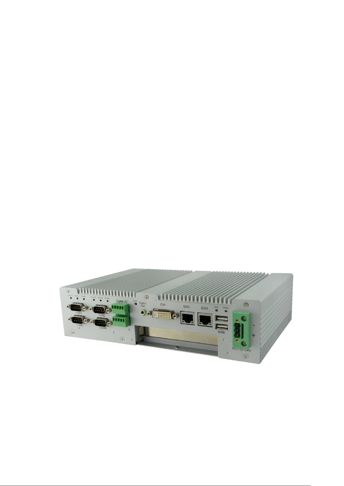
Front Panel
Reset Button x1
USB 2.0 x2
Audio (AC97 audio output)
RJ45 with LED x2 for GLAN
DVI-I connector x1
2x5 Terminal Block connector x1
DB-9 Male connector x2 for RS-232, RS-422 or RS-485 (BIOS Control)
DB-9 Male connector x2 for RS-232
Terminal Block (TB) 3-pin Connector DC +12 ~ +24V
Amber LED indicator x 6 for RS232/422/485 status display
Green LED indicator x 2 for Power & HDD active status
Rear Panel
Optional Antenna Opening for Wireless LAN x2
USB 2.0 x2
Optional power jack for DC +12 ~ +24V input
Optional DB-9 opening x4
Internal I/O Connectors
PCI-E x16 slot (PCI + PCI-e 1x Signals)
SATA connector x1
4-pin +5V power connector x1
System fan 4-pin connector x1
2-pin DC +12 ~ +24V connector x2
CFast Card Socket x1
Mini PCI-E Socket x1
DDR3 SO-DIMM Socket x1
4 ports USB 2.0 pin header
LVDS connector x1
Expansion Slot
Standard Full Height Slot opening on Front panel supports add-on card
length up to 122 mm
Dimensions
252 (W) x 162 (D) x 64 (H) mm
Operation Temperature
0 ~ 45℃
Storage Temperature
-20 ~ 70℃
Operation Humidity
5% ~ 90% @ 45℃, non-condensing
AMS100-807 Series User’s Manual
Page 5

4
Anti-vibration
Non-operating: 1.0 grms / 5~500 Hz random operation
Operating: 0.25 grms / 5~500 Hz random operation
Certifications
CE, FCC, UL, CCC
Features
Support IBASE iSMART for auto-scheduler and power resume
EuP/ErP compliant
Switch RS-232 / 422 / 485 mode in BIOS (COM1 & COM2)
Chapter 2 AMS100-807 Series Features
Supports two Gigabit LAN ports
Supports Intel
®
AtomTM D2550 at 1.86GHz processor
DDR3 SO-DIMM x1, up to 4GB
RS-232 / RS-422 / RS-485 function preset with BIOS
RS-485 auto flow control
4 in & 4 out Digital IO
3-pin terminal block or DC Jack +12V ~ +24V DC power input selection
Mini PCI-E slot x1
CFast Card slot x1
Supports PCI (IP807) or PCI-E (IP808) Riser Card
Supports iSMART feature
EuP / ErP compliant
Fanless design
AMS100-807 Series User’s Manual
Page 6

5
Chapter 3 System Dimensions
Unit: mm
AMS100-807 Series User’s Manual
Page 7

6
Fig. 4-1 Loosen three #6-32 screws on front panel.
Fig. 4-2 Loosen Four M3 screws on rear & top
panel. Top screw is shorter.
Fig. 4-3 The system
Fig. 5-1 Insert DDR3 SO-DIMM memory module.
Chapter 4 Opening the Chassis
Chapter 5 Installing the Memory Module
AMS100-807 Series User’s Manual
Page 8

7
Fig. 6-1 Loosen four screws to remove HDD
bracket.
Fig. 6-2 Insert the SATA cable
Fig. 6-3 Put HDD on the bracket Fig. 6-4 Assemble cable and HDD
shoulder screw
Fig. 6-5 Fasten HDD on bracket with four shoulder screws.
Chapter 6 Installing the 2.5” HDD
AMS100-807 Series User’s Manual
Page 9

8
Fig. 6-6 Fasten HDD bracket with four screws.
Fig. 7-1 Insert Mini PCI-E module and fixed with two M2 screws.
Fig. 8-1 Screw tight the DC cables.
Fig. 8-2 Plug TB onto AMS100-807.
Cathode
Anode
Ground
Chapter 7 Installing the Mini PCI-e Module
Chapter 8 Terminal Block (TB) DC Input
AMS100-807 Series User’s Manual
Page 10

9
Chapter 9 Rear USB Cable
COM 5 & 6 cable
Fig. 10-1 Knock off two DB-9 opening and screw
RS-232 connectors on chassis.
Fig. 10-2 Plug COM 5 & COM 6 cable onto the
motherboard.
Fig. 9-1 Plug USB cable onto the motherboard.
Chapter 10 Rear COM 5 & COM6 Cable (Optional)
AMS100-807 Series User’s Manual
Page 11

10
Chapter 11 Installing the Add-on Card
IP807 --- PCI Riser Card
IP808 --- PCI-E Riser Card
Fig. 11-1 Make sure the add-on card interface.
Fig. 11-2 Loosen slot screw.
Fig. 11-3 Remove HDD kit.
Fig. 11-4 Insert add-on card and fasten the screw.
Fig. 11-5 Assemble HDD and make sure the guide
rail fits the add-on card.
AMS100-807 Series User’s Manual
Page 12

11
Chapter 12 Assembling Mounting Brackets
Fig. 12-1 Put mounting brackets on bottom and fasten
with four screws.
Chapter 13 Optional COM7 & COM8 Assembly
Fig. 13-1 IBD-182V, IBASE RS-232 Mini PCI-E card Fig. 13-2 Insert IBD-182V and fixed with two M2 screws.
Fig. 13-3 Plug COM port cables onto IBD-182V Fig. 13-4 COM7 & COM 8
AMS100-807 Series User’s Manual
 Loading...