

Page 1

Page 2

Page 3

Table of Contents
Instruction Manual
日本語 安全にお使いいただくために ........................................................ 2
メンテナンスマニュアル ............................................................... 4
調整マニュアル ............................................................................. 9
ENGLISH Maintenance Manual ................................................................... 35
Adjustment Manual ...................................................................... 40
DEUTSCH Wartungs- und Pfl egehinweise .................................................... 64
Einstellungsanleitung .................................................................. 69
FRANÇAIS Manuel dʼentretien ....................................................................... 93
Réglage manuel .......................................................................... 98
ESPAÑOL Manual de mantenimiento ......................................................... 122
Manual de ajustes ..................................................................... 127
ITALIANO Manuale di manutenzione ......................................................... 151
Manuale di regolazione ............................................................. 156
ᒦᆪ
Guitar Electronics .............................................................................................. 209
Guitar Controls .................................................................................................. 210
Thank you for purchasing an Ibanez guitar. In order to keep your guitar in the
best possible condition, please read this manual for information on care and
adjustment.
ᆒઐۣዸ၄ݿ
ࢯᑳ၄ݿ
.................................................................................... 185
............................................................................. 180
Page 4
はじめにお読みください
日本語 安全にお使いいただくために
安全にお使いいただくために
本製品をお買い上げいただきまして、まことにありがとうござい
ます。この冊子では、安全にお使いいただく上でお気をつけてい
ただきたい点と、お手入れの際の注意点がまとめてあります。
表示記号について
本書では、本機を安全に正しくご使用いただき、あなたや他の
人々への危害や財産への損害を未然に防ぐために事項を下記の記
号で表示しています。
この表示を無視して、誤った取り扱いをす
警告
注意
お願い
●外部要因によって生じた本機の故障、不具合などの損害に
つきましては、当社は一切の責任を負いかねますので、あ
らかじめご了承ください。
ると、人が死亡または重傷を負う可能性が
想定される内容を示しています。
この表示を無視して、誤った取り扱いをす
ると、人が傷害を負う可能性が想定される
内容および物的損害のみの発生が想定され
る内容を示しています。
この表示を無視して、誤った取り扱いをす
ると、本商品の本来の性能を発揮できな
かったり、機能停止をまねく内容を示して
います。
注意
楽器を振り回さないでください。
プロのステージアクションをまね
て、演奏中にギターを振り回した
り体のまわりでギターを回したり
すると、ギターがストラップから
外れたりし、まわりの人に当たっ
てけがをさせるなどの事故の原因
になりますのでおやめください。
演奏中に顔を楽器に近づけないでください。
ギターの低音弦やベース等の太い弦が切
れた場合、手や顔に当たってけがをする
恐れがあります。弦が切れる前にこまめ
に新しいものと交換してください。特に
目に弦が当たった場合などは失明の危険
がありますので演奏中に弦に顔を近づけ
ることはおやめください。
ギター、ベース用弦は消耗品です。弦が
古くなっていると、通常の弾きかたをし
ているにもかかわらず(特別に強く弾い
たりしなくても)、演奏中に弦が切れて
しまう場合があります。
警告
湿気の多い場所では演奏しないでください。
感電の恐れがありますので、直接雨がかかる野外や風呂場などの
湿気の多い場所では演奏しないでください。
極端な大音量で鳴らさないでください。
ギターアンプ、ヘッドフォンを使用する場合に、長時間大音量で
使用していると回復できない難聴になる恐れがあります。またア
ンプの故障の原因にもなりますので、極端な大音量での使用は避
けてください。
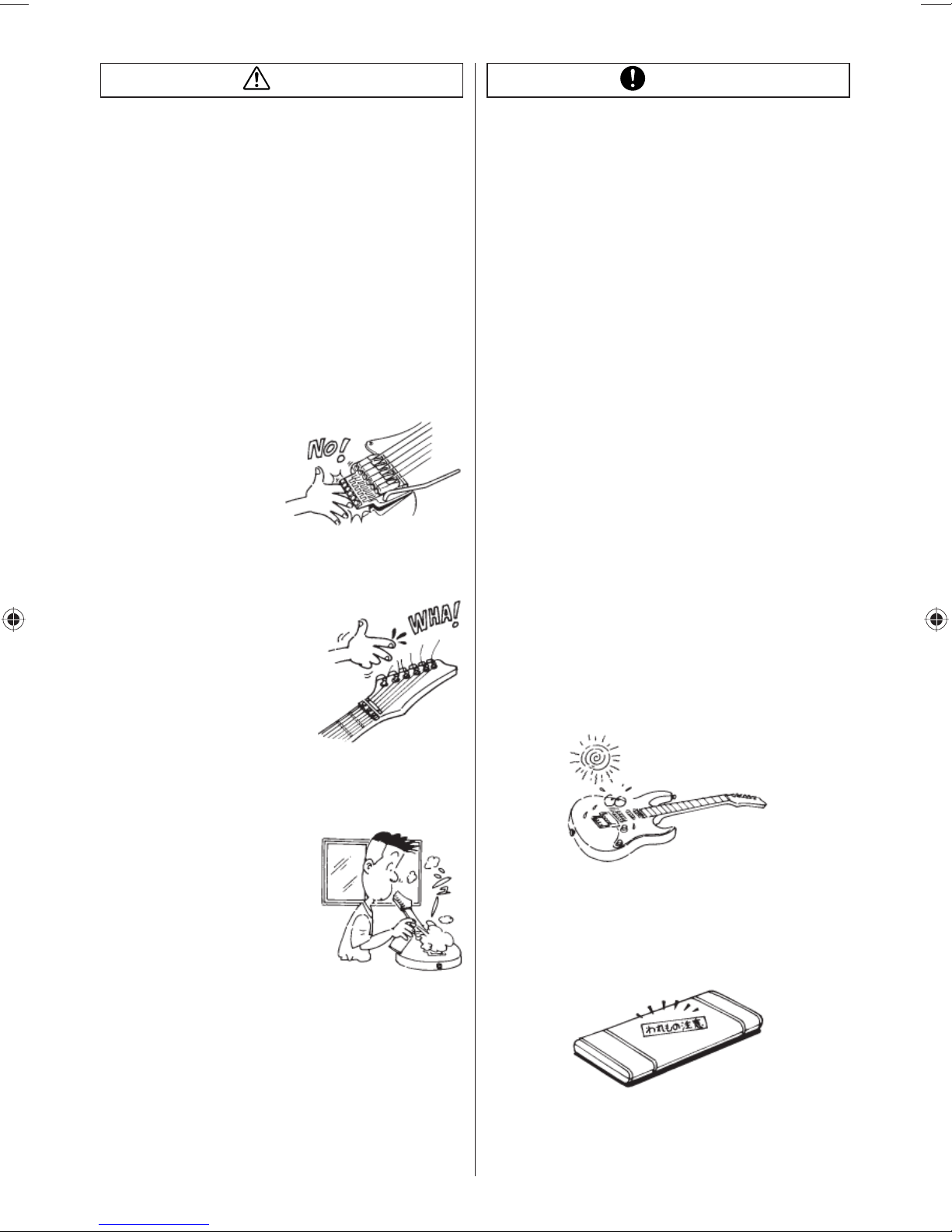
さびた弦を使わないでください。
弦(特にギターの1、2、3弦)が
さびてくると、弦で指を切ってけが
をする恐れがあります。こまめに弦
を新しいものと交換してください。
ストラップがゆるんだまま演奏しないでください。
ストラップを使って立って演奏する場合は、ストラップが確実に
ストラップビンにかかっていることを確認してください。ギター
が足の上などに落下してけがをする恐れがあります。
ピックガードの尖ったところに注意してください。
エレクトリックギターの一部のモデルでは、デザイン上ピックカー
ドの先端部分が非常に鋭くなっています。ピッキングの際やクロス
で清掃するときなどにけがをしないようにご注意ください。
2
Page 5
注意
お願い
フレットのエッジ部分でのけがに注意してください。
ギターのネックは木製品ですので、モデルによってはまれにネック
の乾燥によってフレットがネックからはみ出してくることがありま
す。このような状態で演奏すると、フレットの端で手を傷つける恐
れがあります。万一このようになった場合は、直ちに演奏を中止し
てお買い求めになった販売店に修理を依頼してください。
無理に弦を張らないでください。
弦を張る場合は、本来の音程以上に強く巻かないよう、チューニン
グをしながら丁寧に巻いてください。必要以上に強く弦を巻いてし
まうと、新品の弦であっても切れてけがをする恐れがあります。
また、切れた弦が目に当たった場合などは失明の危険がありますの
で、弦を交換する際は、弦に顔を近づけることはおやめください。
トレモロに指をはさまないよう注意してください。
トレモロシステムには弦の張力
を支えるために非常に強いばね
を使用しています。弦を交換す
る場合など、トレモロ部分で指
をはさんでけがをしないように
ご注意ください。
弦で手を傷つかないよう注意してください。
弦の切断部分(特にギターの1、2、
3弦)は非常に鋭くなっており、直接
触れると手を傷つける恐れがありま
す。特にギターのヘッドをクロスな
どで清掃する場合に、糸巻きの部分
に手が当たってけがをしないように
ご注意ください。弦を交換したら、
弦の余った部分が指に当たらない程
度まで短く切っておきましょう。
古くなった電池を楽器に入れたままにしないで
ください。
乾電池を使用した製品では、乾電池の液漏れ等にご注意くださ
い。また、乾電池は使用しない場合でも自然に放電してしまう特
性がありますので、定期的に交換することをおすすめします。乾
電池を捨てる場合は、自治体、電気店等の専用の回収箱をご利用
ください。また、使用済みの乾電池を火の中に入れると爆発する
恐れがあり非常に危険です。
ギターの表面を樹脂製品などに接触させたまま
保管しないでください。
樹脂製品や家具などの塗装されたものに、ギターの表面を直接長
時間接触させた場合、色移りしたり溶着したりしてお互い損なう
恐れがあります。ギターケース、バッグに入れておくか、布製の
袋に入れるなどして直接それらに接触しないように保管してくだ
さい。
ベンジン、シンナーでは拭かないでください。
ギターの表面をクリーニングする場合にベンジン、シンナー等の
薬品を使用すると、変質したり変色したりする恐れがあります。
ギター用として販売されているクリーナーをご使用ください。
保管、運送などでは以下のような点にお気をつけ
てください。
●ギターは木製品です。投げたり落としたりすると容易に破損し
てしまいます。丁寧にお取り扱いください。
●高温・多湿の場所、砂やほこりの多い場所を避け、換気の良い
場所に保管してください。
●
直射日光が当たると、塗装等の色があせてくる恐れがあります。
●雨の中で演奏するなどしてギターに直接水分がかかったり、
炎天下での演奏など高温の場所に長時間さらされると、ボ
ディー、ネック等の木部に狂いを生じる恐れがあります。
換気の悪い場所ではスプレー式クリーナーを使
わないでください。
スプレー式のギタークリーナーなど
を使用する場合は、換気に注意して
ください。風通しの悪い場所で使用
すると中毒症状を起こす恐れがあり
ます。また可燃性のものは火気に十
分注意して作業してください。
ケースのふたやバッグのファスナーを開けたま
ま持ち運ばないでください。
ギターケース、バッグに入れて持ち運ぶ場合は、ケースの留め金
やファスナーがしっかりとかかっていることを確認してくださ
い。ふたが開いてギターが落下する場合があります。
●宅急便などを利用して輸送する場合は専用のハードギターケー
スを使用するか、丈夫なカートンを使用して緩衝材を十分つ
めて梱包し、ワレモノ扱いにしてください。楽器店で購入し
たときのカートンは運送用には適していない場合があり、そ
のまま出荷すると破損する恐れがあります。
3
Page 6

メンテナンス
メンテナンスマニュアル
付属品
マルチツール トレモロアーム
PREMIUMシリーズ
Edgeトレモロ・ブリッジ
PREMIUMシリーズ
Edge-ZeroIIw/ZPS
PREMIUMシリーズ
Z R トレモロ・ブリッジw/ZPS2
PREMIUMシリーズ
Tight-EndRブリッジ
EdgeⅢトレモロ・ブリッジ ○ ○○○○
Edge-ZeroIIw/ZPS ○ ○ ○ ○
Edge-ZeroIIw/oZPS ○ ○ ○ ○
FAT6トレモロ・ブリッジ ○ ○ ○ ○
FAT10トレモロ・ブリッジ ○ ○ ○ ○
FXEdgeⅢブリッジ ○○○
FXEdgeⅢ-8 ブリッジ ○○○
GibraltarStandardブリッジ ○ ○ ○
GibraltarStandard 7ブリッジ ○ ○ ○
SAT10トレモロ・ブリッジ ○ ○ ○○
SAT-ProⅡトレモロ・ブリッジ ○ ○ ○○
STDトレモロ・ブリッジ ○
STD-DLトレモロ・ブリッジ ○
Tight-Endブリッジ ○ ○
Tight-Tuneブリッジ ○ ○○
Z R トレモロ・ブリッジw/ZPS2 ○ ○ ○○
○○
○○
○○
○
1.5mm 2mm 2.5mm 3mm 4mm
六角レンチ
DiMarzio社製ピックアップ搭載モデルには、ポールピース高調整用六角レンチが付属します。※
7弦用Edge-Zero2トレモロ・ブリッジw/ZPS3Fe搭載モデルには、強化スプリングが付属します。※
4
Page 7
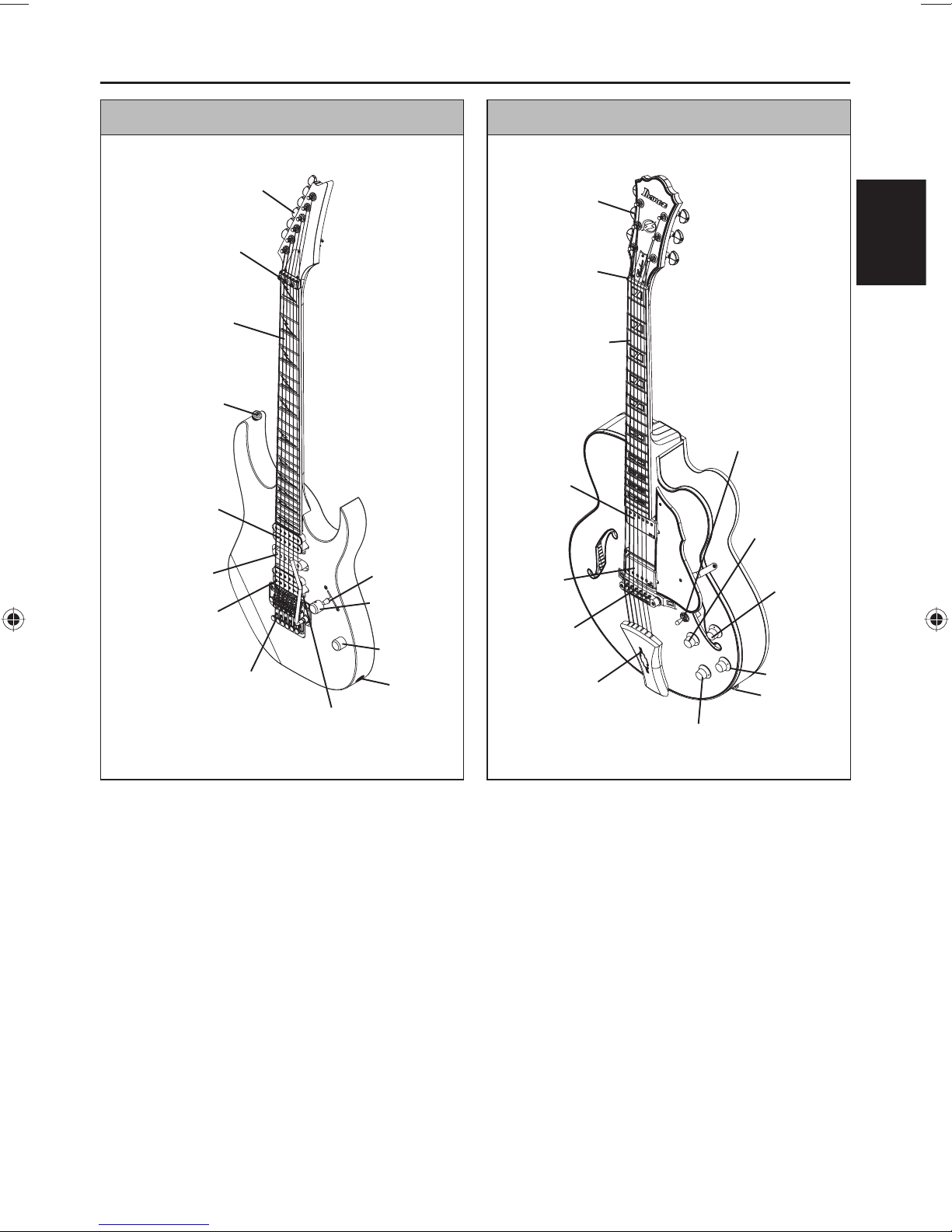
本体各部の名称
エレクトリックギター セミ、フルアコースティックギター
糸巻き(ペグ)
ロッキング ナット
指板
(フィンガーボード)
ストラップピ ン
ネックピックアップ
ミド ル
ピックアップ
ブリッジ
ピックアップ
トレモロ
出力ジャック
トレモロアーム
ピックアップ
セレクター
ボリューム
トーン
糸巻き(ペグ)
ナット
指板
(フィンガーボード)
ネック
ピックアップ
ブリッジ
ピックアップ
ブリッジ
テールピース
日本語
ピックアップ
セレクター
ネック
ピックアップ
ボリューム
ブリッジ
ピックアップ
ボリューム
ブリッジ
ピック
アップ
トーン
出力ジャック
ネックピックアップトーン
イラストはIbanezの代表的なモデルです。お買い求めのギターが必ずしもイラストと一致しない場合があります。※
トレモロ/ブリッジの調整については、搭載されているトレモロ/ブリッジにより異なります。※
詳しくは該当のトレモロ/ブリッジ項をご確認ください。
各モデルのコントロールについては、「CONTROLS」項(P210)をご確認ください。※
5
Page 8
チューニング
Ibanezのギターは、出荷時に下記のチューニングで各部の調整を行っています。
1st 2nd 3rd 4th 5th 6th 7th
6-strings E4 B3 G3 D3 A2 E2 7-strings E4 B3 G3 D3 A2 E2 B1
例外として、下記のモデルがあります。
RGD、APEX2
1st 2nd 3rd 4th 5th 6th 7th
6-strings D4 A3 F3 C3 G2 D2 7-strings D4 A3 F3 C3 G2 D2 A1
RG8、RGA8、S8、S8QM、RGIR28FE
1st 2nd 3rd 4th 5th 6th 7th 8th
D#4 A#3 F#3 C#3 G#2 D#2 A#1 F1
MTM100
1st 2nd 3rd 4th 5th 6th 7th 8th
C# G# E B F# B - -
演奏、調整の際はチューニングメーターや音叉等を使用し、各弦の開放音を上記の音程にチューニングしてくださ
い。音程が高い場合は一度弦を緩めて音程を少し下げた後、巻き上げながら音程を合わせるようにするとチュー
ニングが安定しやすくなります。表の音程以外でチューニングをする場合、または標準と異なるゲージの弦を使用
する場合には、ネックの調整やイントネーションの調整が必要になる場合があります。
ネックの調整、イントネーションの調整についてはそれぞれ「ネック調整」項(P7)、「弦長(イントネーション)」項
(P7)をご確認ください。
ご注意
極端なチューニングやエレキギター弦以外の弦の使用は、部品の破損や思わぬ怪我に繋がることがありますの•
でご注意ください。
弦の交換
弦は使用しているうちに劣化し性能が低下するため、ビレや音程の狂いが生じることがあります。
弦に錆や変色が見られる場合や、音質の低下、音のビリつきが酷くなったと感じた場合には弦を交換してください。
全ての弦を同時期に交換されることをお勧めします。
折れ、ねじれ、傷等がある弦は本来の性能を発揮できませんので、ご使用にならないでください。
弦は糸巻き(ペグ)のポストから下へ2〜3回、長さにして5〜7cmを目
安に、弦が交差しないように巻きます。
交換作業は全ての弦を一度に外してしまわずに1本ずつ交換を行うこ
とで、ネックにかかる急激な力の変化やトレモロのバランスを崩してし
まうリスクを軽減できます。
※トレモロ/ブリッジに取り付けられた弦の着脱方法は、搭載されているトレモロ/ブリッジにより異なります。
詳しくは該当のトレモロ/ブリッジ項をご確認ください。
6
Page 9
弦高
弦高とはフレットと弦との距離のことです。
弦高の測定は、正確にチューニングを行った後、14フレットに定規をあて、フレットの
先端から弦の下端までの距離を測定します。
弦高の目安は、1弦で1.5〜1.7mm、6弦で2.0mm〜2.2mmです。
7弦ギターの場合は7弦で2.2mm〜2.4mm、8弦ギターは8弦で2.4mm〜2.6mmに
なります。
上記の弦以外の弦高は、1弦から最低音弦へ向かって徐々に隙間が大きくなるように設定してください。
弦高が高すぎると演奏性が悪化し、低すぎると弦ビレや音詰まり、サスティーンの劣化等を招きます。
弦高を適正な値にしても弦ビレや音詰まりが発生する場合には、ネックの反りを調整する必要がある可能性があ
ります。
詳しくは「ネック調整」項(P7)をご確認ください。
弦高調整の方法は、搭載されているトレモロ/ブリッジの種類によって異なります。詳しくは 該 当トレ モロ/ブリッジ 項を※
ご確認ください。
弦長(イントネーション)
弦のゲージを変更したり、変則チューニングでギターを
使用する場合には、全てのフレットで正しい音程が得ら
れるように、弦の長さ(イントネーション)を調整する必
要があります。
正確にチューニングを行った後、演奏時の状態にギタ
ーを持ち、各弦の12フレットを押さえたときの音と、12
フレット上でのハーモニクス音とを比較します。
12フレット上でのハーモニクス音よりも12フレットを押
さえたときの音の方が音程が低い場合は、トレモロ/ブ
リッジのサドルを前方に動かして弦長を短くします。12フレットを押さえたときの音の方が高い場合は、サドルを
後方に動かして弦長を長くします。
12F
日本語
正確なイントネーション調整を行うため、チューニングメーターを使用してください。※
サドル位置の調整方法は、搭載されているトレモロ/ブリッジにより異なります。詳しくは該当のトレモロ/ブリッジ項をご※
確認ください。
ネック調整
ネックには常に弦の張力がかかっており、チューニングの状態や弦のゲージを変更したときだけでなく、温度や湿
度の変化によっても反り具合が微妙に変化します。
適正な弦高調整とチューニングを行ってもビレや音詰まりが発生する場合は、ネックの反り具合を確 認し、調整す
る必要があります。
1ネックの状態を確認します。
正確にチューニングを行った後、演奏時の状態にギターを
持ち、1弦の1フレットと、ネックとボディの接合部分に最も
近いフレットの両方を押さえた状態で、8フレットでの弦と
フレットとの 隙間を測ります。
同様に最低音弦でも測定し、それぞれの隙間が
0.3mm〜0.5mmになるように調整します。
2 隙間が0.3mmよりも小さい場合は、ネックのヘッド側に取
り付けられ たアジャストナットを六角レンチやソケットレ
ンチを使用してA方向へ回して、ネックを順反り方向へ動
かします。
8th fret
7
Page 10
3隙間が0.5mmよりも大きい場合は、アジャストナットをB
方向に 回して、ネックを逆反り方向に動かします。
アジャストナットは1/4回転を目安に、チューニングを確認※
しな がら少しずつ行ってください 。
ご注意
ネックの調整には十分な注意が必要です。•
無理な調整は故障の原因となりますので、正しく調整ができない場合はお買い求めの楽器店または弊社へご相
談ください。
お手入れ
演奏後は錆の発生を防ぐため、弦の裏側やフレット、
ブリッジサドルやナット等の金属部品に付着した汗や油
を拭き取ってください。金属部品に付着した埃や汚れ等
は部品の機能に障害を及ぼすことがありますのでご注
意下さい。
通常の拭きあげでは除去できない汚れは、少量の油を
染み込ませた柔らかい布を使用して除去します。
トレモロアームを回したときに異音が発生する場合は、
トレモロアーム先端の窪み部分にグリスを塗布してくださ
い。
塗装面のお手入れは、揮発性の薬品や研磨剤の使用は避け、楽器専用のポリッシュを染み込ませた柔らかい布で
丁寧に拭きあげてください。
オイルフィニッシュ仕上げのボディーやネックの汚れを除去する場合は、消しゴムや#1000以上の細目のサンドペ
ーパー、#0000のスチールウール等を使用してください
年に1〜2回、家具用等の無色の仕上げオイルやガンオイルを少量使用して拭きあげると、乾燥を防止することが
できます。
塗装が施されていない指板面には、指板用のオイルや良質のレモンオイル等を少量含ませた布で、フレットの際
まで丁寧に拭いてください。
バッテリー
プリアンプやイコライザー等を搭載したギターには、バッテリーが使用されています。
音量が小さくなる、音が歪む等機能の低下が見られる場合は、バッテリーを 交換してください。
006P(9V)のバッテリーを搭載するモデルと、単三(1.5V)2本を搭載するモデルがあります。
お買い上げのギターに搭載されているバッテリーの種類をご確認の上、同じタイプのバッテリーをご使用ください。
バッテリーはボディー裏側のバッテリーボックスに収納されています。
バッテリー搭載モデルは出力ジャックが電源スイッチを兼ねており、ジャックにプラグを挿入することで電源がオ
ンになります。
ご注意
バッテリーの消耗を防ぐため、長時間ご使用にならない場合はジャックからプラグを抜いて保管してください•
8
Page 11
ギターブリッジ
調整マニュアル
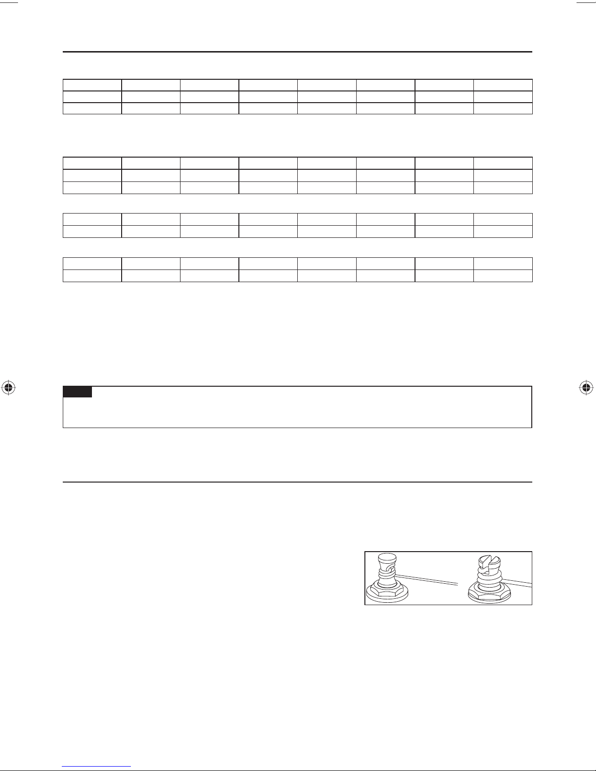
ジブラルタルIII(ギター、ベース)、CB3&フルチューンIII、ARTブリッジ
弦高はブリッジ両側にある弦高調整スク
リュー(A)をマイナスドライバーで回して
調整します。イントネーション調整は、ブ
リッジ後部の調整スクリュー(B)をプラス
あるいはマイナスドライバー、または付属
の六角レンチで回し、サドルを移動させて
調整します。
GIBRALTARIII,CB3
CB3ブリッジの弦交換は、ブリッジ前部から弦穴を通過させて行います。
ジブラルタルⅢブリッジの弦高調整の際は、スクリューを無理に回してネジ穴が傷 ※
つかないよう、十分に弦をゆるめてから行ってください。
フィックスドブリッジ
弦はギターボディー裏側から、弦止めフェラルを通して取り付けます。
弦高は各サドルの高さを付属の六角レンチ(1.5mm)で回して調整しま
す。イントネーションはブリッジ後方から各サドルのイントネーション
調整ボルトをプラスドライバーで回して調整します。
(A)
(B)
(B)
FULLTUNEII,
ART1,ART2
日本語
(A)
7弦用も調整方法は同じです。 ※
ジブラルタルスタンダードブリッジ(7弦用/8弦用)
弦はギターボディー裏側から、弦止めフェラルを通して取り付ける方式と
ブリッジ後方部よりボールエンドを引っ掛けて止める方式(A)の2通りが
可能です。
弦高は各サドルの高さを付属の六角レンチ(1.5mm)で回して調整します
(B)。
イントネーションはブリッジ後方から各サドルのイントネーション調整ボ
ルトを付属の六角レンチ(2.5mm)で回して調整します(C)。
7弦用/8弦用も調整方法は同じです。 ※
(A)
(B)
(C)
9
Page 12
アジャスタブルアーチトップブリッジ
弦高調整は、ブリッジ左右のアジャスト・スピナー(A)を指で回して、ブ
リッジ全体の高さを調整します(各弦の調整は行えません)。
イントネーション調整は、弦を緩めてブリッジ全体を前後させて調整し、
チューニングを行ってからイントネーションを確認します。正しいイント
ネーションが得られるまで同じ調整を繰り返してください。また、ブリッジ
が倒れないよう注意して行ってください。
弦交換を行うときは、ブリッジの位置がずれないよう、弦を1本ずつ交換することをお勧めします。
ビンテージビブラート
弦交換は1本ずつ行います。ボールエンドをバー(B)のポストに取り付
け、バーの上を渡し、糸巻きに弦を巻きます。リテイナーバー(A)のあ
るモデル(VBX60、VBS80)は、バーの上を渡した後リテイナーバーの下
を通過させ、糸巻きに弦を巻きます。交換作業の間は、絶えず弦を糸巻
き側に軽く引寄せて、ボールエンドがポストから外れないよう注意して
ください。
弦がブリッジサドルに正しく位置していることを確認しながらチューニ
ングを行います。チューニングまでの作業が完了した後、次の弦の交換
に移ってください。全ての弦の交換が完了した後、再度全体のチューニ
ングを行います。
ご注意
全ての弦を一度に取り外すと、ギターにかかるテンションの急激な変
化により、ギター各部の状態に大きな影響を与える恐れがあります。弦
交換は1本ずつ行ってください。
テールピース
クイックチェンジIII テールピース
テールピース本体左右のスタッド・ボルトをマイナスドライバーやコイ
ンで回して、テールピースの高さを調整します。
(B)
(A)
VBX60
VBS80
(B)
VBF70
(C)
弦交換を行う時は、テールピースの溝に通し、ボールエンドをテール
ピース後方に引っ掛けます。
10
QUIKCHANGEIII
Page 13
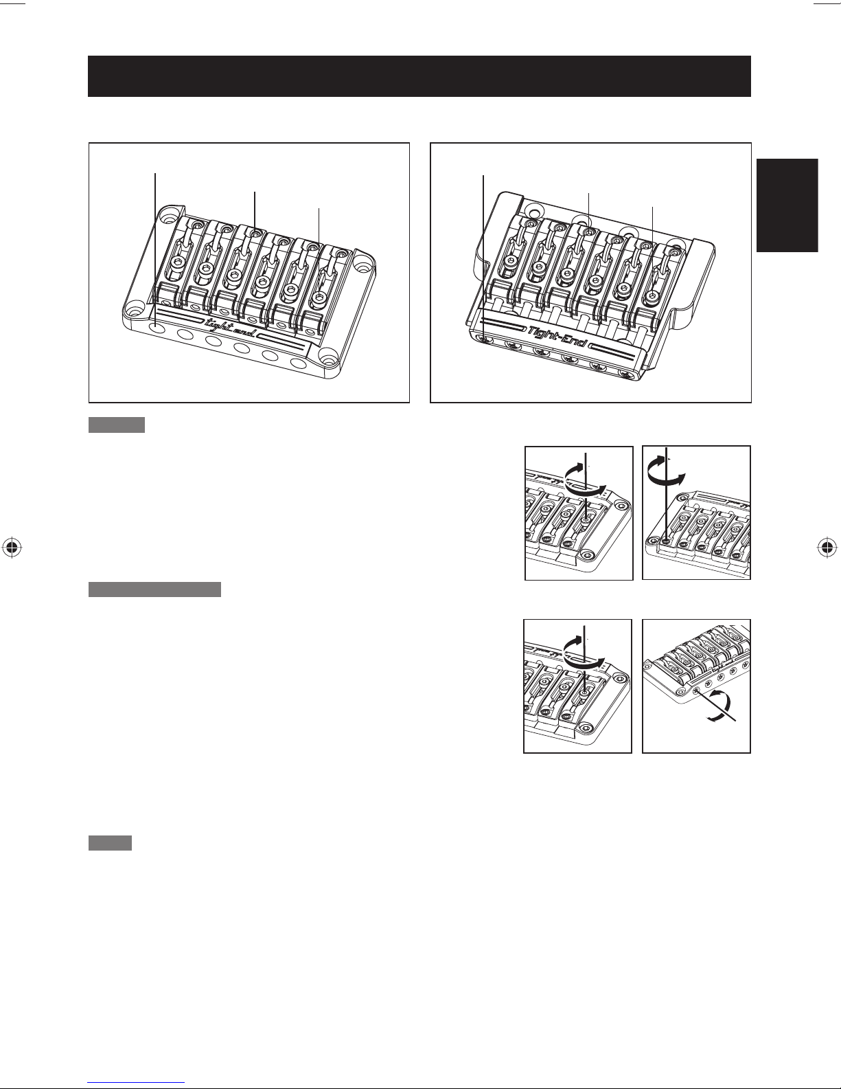
Tight-Endブリッジ/Tight-EndRブリッジ(6弦用/7弦用)
Tight-Endブリッジ■ Tight-EndRブリッジ■
イントネーション調整ボルト
高さ調整スクリュー
サドル・ロック・ボ ルト
弦高調整
1サドル・ロック・ボ ル ト を 六 角 レ ン チ(2mm)で緩めます。
2サドルの高さ調整スクリューを六角レンチ(2mm)で回して、サドルの高さ
を調整します。
調整が終わりましたら、サドル・ロック・ボルト締めてください。※
イントネーション調整ボルト
高さ調整スクリュー
サドル・ロック・ボ ルト
日本語
イントネーション調整
1
サドル・ロック・ボ ル ト を 六角レンチ(2mm)で緩めます。
2イントネーション調整ボルトをプラスドライバーで回して、サドル位置
を調整します。
3サドル・ロック・ボ ル ト を 六角レンチ(2mm)で締め、イントネーション
調整スクリューをプラスドライバーで時計方向に軽く(サドルの位置
に影響が出ない程度)に締めます。
イントネーションの確認は、正しいチューニングで 行ってください。※
弦交換
弦をギターのボディ裏側から、弦止めフェラル を通して取り付 けます。
11
Page 14
Tight-Tuneブリッジ
Tight-Tuneブリッジは、ブリッジの各可動部分をロックすることにより、無駄な振動を抑え、効率の良いサステイ
ンを得られるブリッジです。ブリッジにはより強固にブリッジとボディを固定するためのスタッド・ロック機能を
備えています。また、テールピースにはボールエンドが外れないように保持するボールエンド・ロック機能を装備
しました。
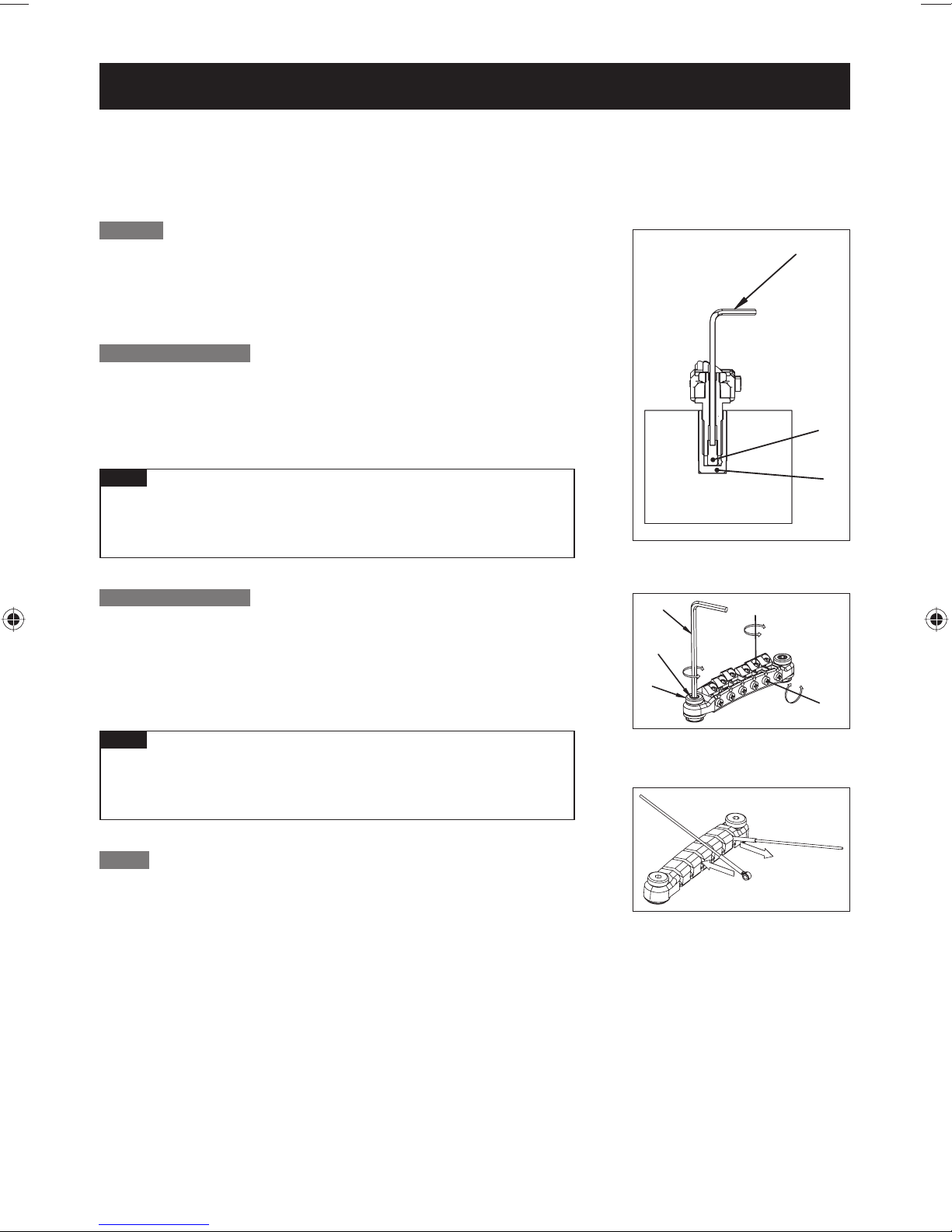
弦高調整
ブリッジ本体左右のロック・ナット(D)を緩め、六角レンチ(3mm)で
スタッド・ボルト(E)を回して、ブリッジ全体の高さを調整します(各弦
の調整は行えません)。調整が完了した後、ロック・ナットを締めてくだ
さい。
スタッド・ロック機能
弦高調整を終えた後、六角レンチ(2mm)でスタッドボルト内部にあるス
タッド・ロック・ボルト(B)を時計回りに回します。スタッド・ロック・
ボルトがアンカーナット(C)に接触し、それ以上回らなくなるまで締め込
んでください。
A
B
ご注意
弦高の調整を行うときは、必ずスタッド・ロック・ボルト(B)を六角レン
チ(2mm)で反時計回りに十分に緩めてから行ってください。破損の
原因になります。
イントネーション調整
調整するサドルのサドル・ロック・ボ ル ト(G)をプラスドライバーで緩め、イント
ネーション調整スクリュー(H)をプラスドライバーで回してサドル位置を調整
し、チューニングを行ってからイントネーションを確認します。正しいイントネー
ションが得られるまで同じ調整を繰り返した後、サドル・ロック・ボ ルトを 締 め て
くだ さ い 。
ご注意
イントネーション調整ボルト(H)が緩い場合、共振を起こすことがあり
ます。その場合はサドルが動かない程度にイントネーション調整ボル
トを軽く締めてください。
弦交換
弦のボールエンドをテールピースの溝に、
(J)
の向きで取り付けます。ボー
ルエンド・ロック機能により、ボールエンドが保持されます。弦を外す場合
(K)
の方向に弦を引っ張ると簡単に取り外すことができます。
は、
C
F
E
D
G
H
K
J
12
Page 15
ロッキングブリッジ
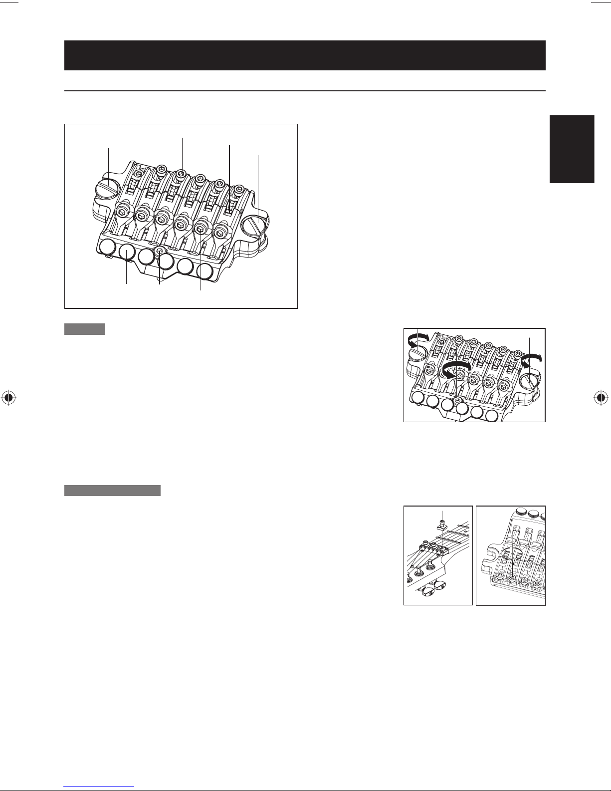
FXEDGEIII/FXEDGEIII-8ブリッジ
FXEdgeIII■
1
2
3
1
1メインスタッド
2サドル・ロック・ボ ルト
3ストリング・ホ ル ダ ー・ブロック
4ストリング・ストッパー・ボ ルト
5リアスタッド
6ファイン・チューニング・ボ ル ト
日本語
6
弦高調整
1ブリッジ本体左右のメイン・スタッドをマイナスドライバーで回して、トレ モロ全
体の高さを動かして弦高を調整します(各弦ごとの調整は行えません)。
2リア・スタッドを六角レンチ(3mm)で回して、ブリッジがギターのボディー表面
とおおよそ平行に
なるように調整します。
5
4
リア・スタッドの調整でも弦高が変化しますので、最終的な弦高の確認はリア・スタッドを調整した後行ってくだ※
さい。またメイン・スタッドの調整の際は、無理に回してネジ穴が傷つかないよう、十分に弦を緩めてから行って
くだ さ い 。
イントネーション調整
1ロッキング・ナットのプレッシャー・パ ッド・ボ ル ト を 六 角 レ ン チ(3mm)で緩め、
十分に弦を緩めます。
2サドル・ロック・ボ ル ト を 六 角 レ ン チ(2mm)で緩め、サドル位置を調整します。
イントネーションの確認は、サドル・ロック・ボルトがしっかりと締まった状態で、※
正しい チューニングで 行ってください。調整が終わりましたら、サドル・ロック・ボ
ルトとロッキング・ナットのプレッシャー・パ ッド・ボ ル ト を 締 め てくだ さ い 。
13
Page 16
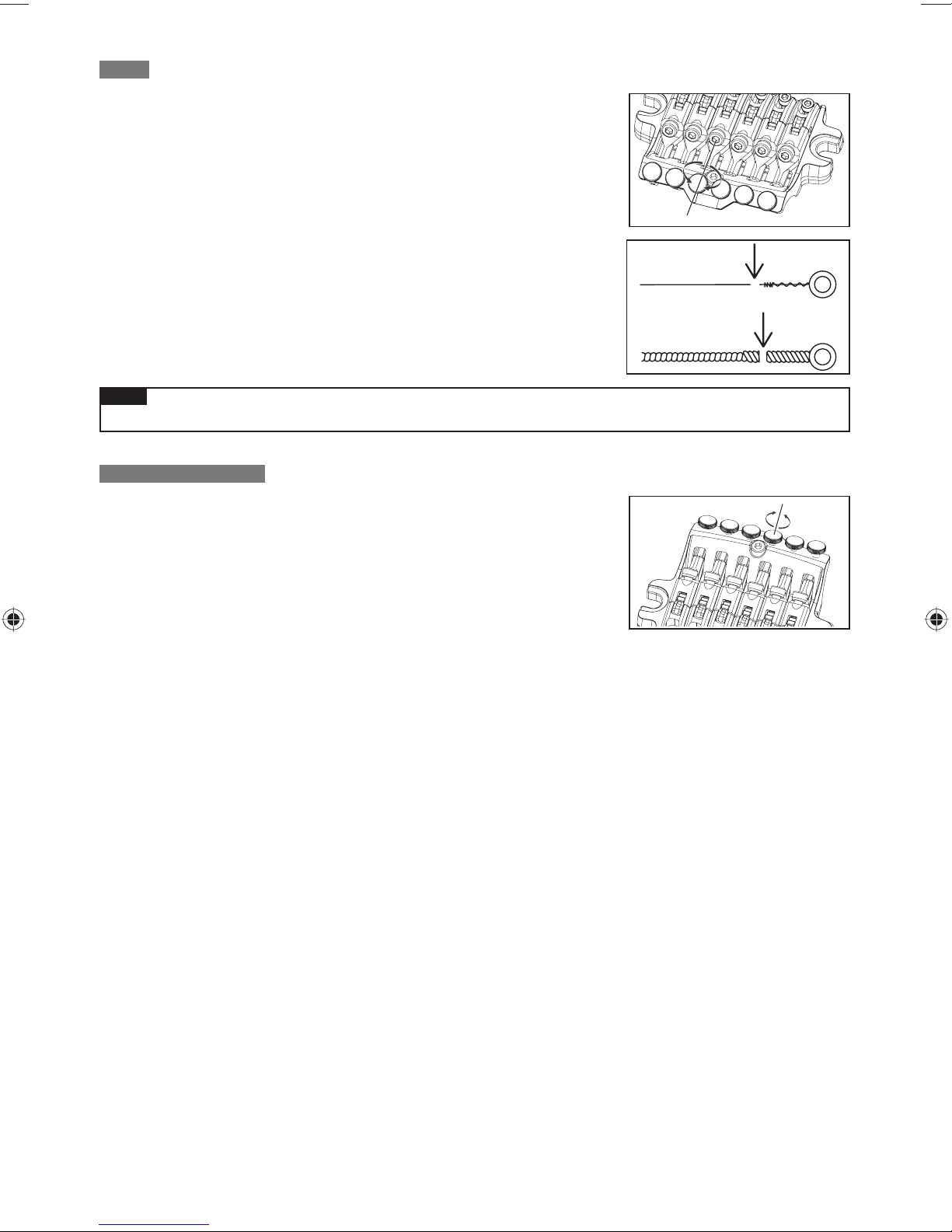
弦交換
1ロッキング・ナットのプレッシャー・パ ッド・ボ ル ト を 六 角 レ ン チ(3mm)で緩め、
糸巻きから弦 を取り外します。
2ブリッジ本体のストリング・ストッパー・ボ ル ト を 六 角 レ ン チ(3mm)で緩め、サド
ルから弦を引き抜いて取り外します。
3新しい弦は先端のボールエンド部分をニッパー等で切り落とします。
4ボールエンドを切り落とした側の弦の先端をサドルとストリング・ホ ル ダ ー・ブロ
ックとの間に挿入し、ストリング・ストッパー・ボルトを締めて弦を固定します。
5糸巻きで弦を巻き上げ、チューニングを行います。
6チューニング完了後、ロッキング・ナットのプレッシャー・パ ッド・ボ ルト を 締 め
ます。
ご注意
チューニングを行う前に、ストリング・ストッパ ー・ボルトがしっかりと締め付けられていることを確認してください。•
ファイン・チューニング
ロッキング・ナットで弦をロックした 後でも、ファイン・チューナーによって各弦の
チューニングの微調整が行えます。
チューニングの前に、あらかじめ全てのファイン・チューニング・ボルトを可動範囲
の中央付近に調整しておくと、弦をロックした後の調整幅を広く持たせることがで
きます。
14
Page 17
ロッキングトレモロ
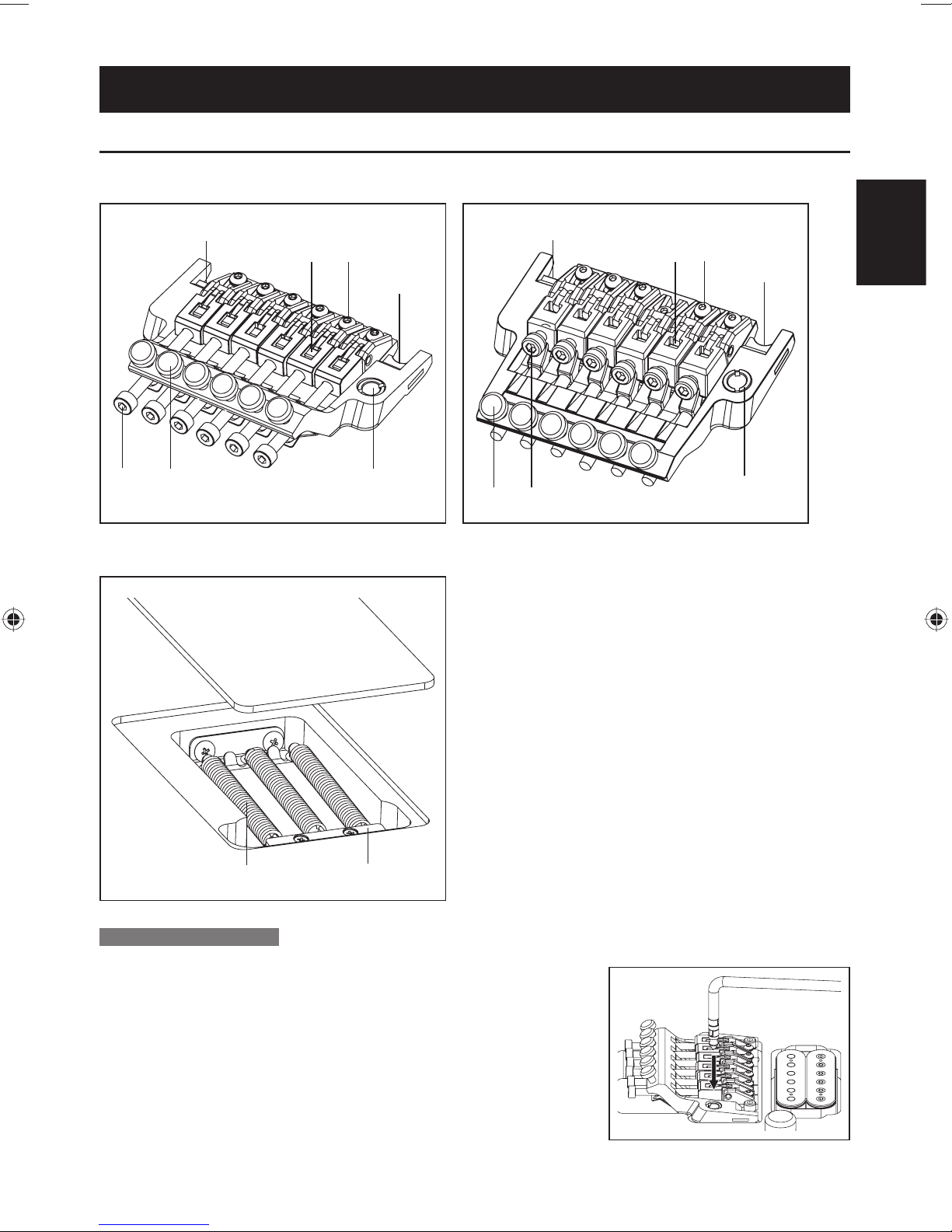
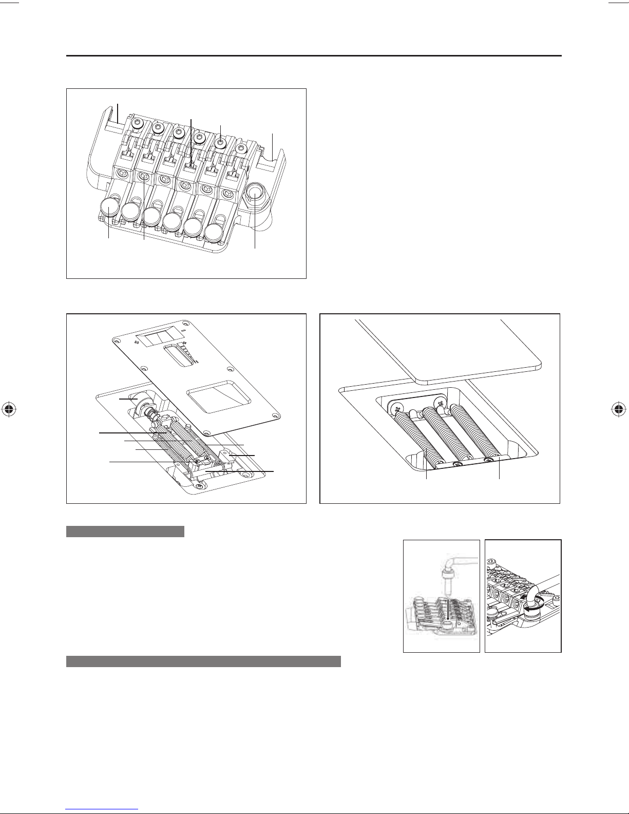
EDGEトレモロブリッジ
Edge■ Lo-ProEdge■
1
3
2
1
5
6
4
背面■
1
3
56
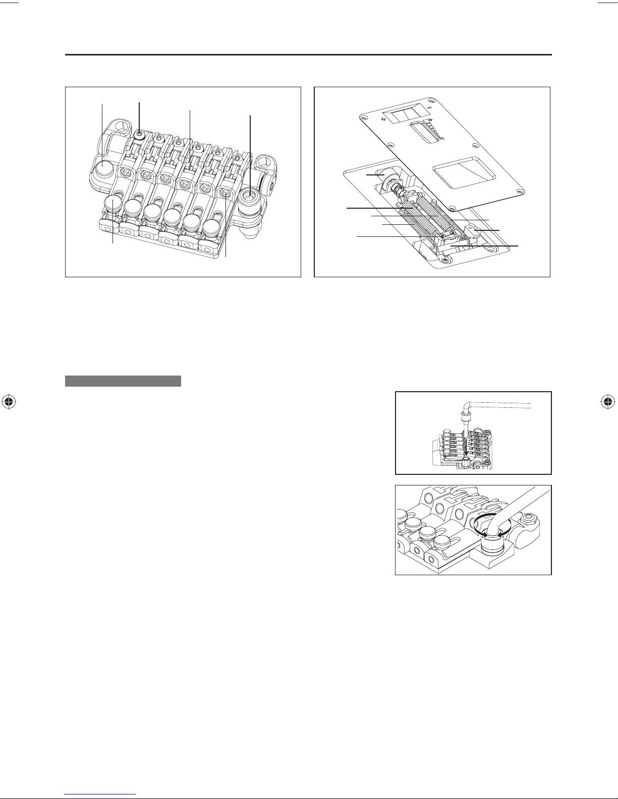
1ナイフエッジ
2サドル・ロック・ボ ル ト
3ストリング・ホ ル ダ ー・ブロック
4アームソケット
5ストリング・ストッパ ー・ボ ル ト
6ファイン・チューニング・ボ ルト
7トレモロ・スプリング
8スプリング・ロック
日本語
2
1
4
7
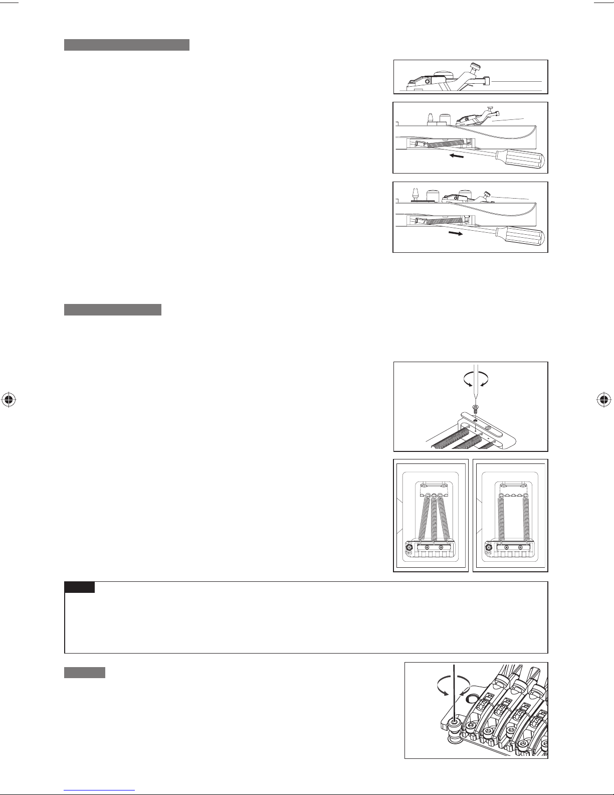
トレモロアームの取り付け
トレモロアームは挿し込み式です。ベースプレートのアームソケットに、トレ
1
モロアームのコーナー部分を持って、テフロンワッシャが完全に隠れるまで
確実に挿し込
みます。
8
15
Page 18
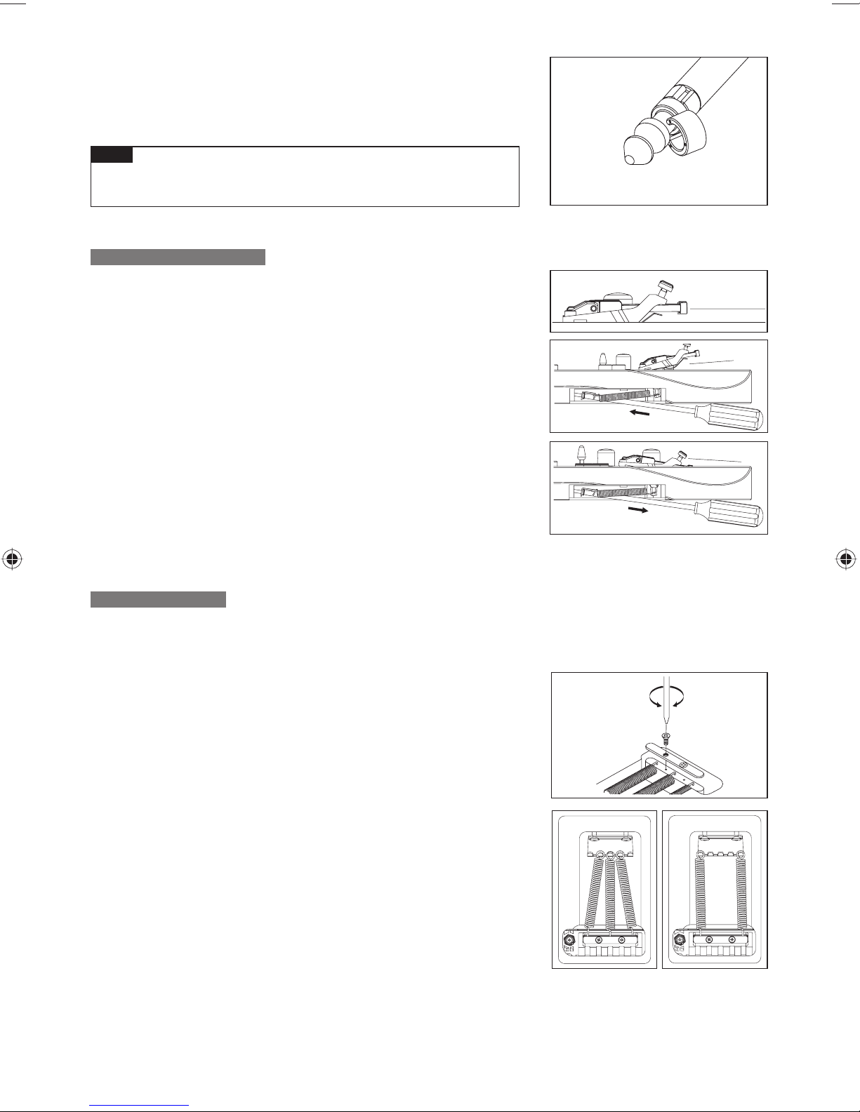
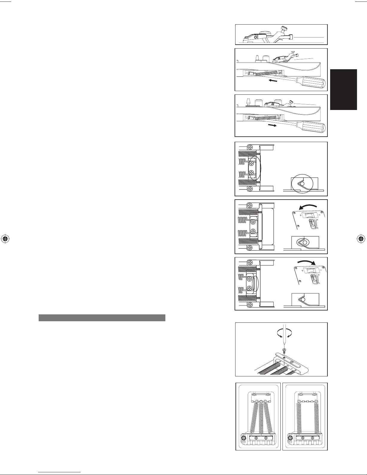
2トレモロアームの締め付けは、テフロンワッシャの着脱で調整します。
数が増えるほど締め付けが増し、全て外すとフリーになります。テフロン
ワッシャはスリット部分から斜めに着脱します。
ご注意
テフロンワッシャを装着していても十分な締め付けが得られなくな•
った場合は、新しいワッシャと交 換してください。
トレモロの取り付け角度調整
トレモロの取り付け角度は、弦の張力とギターのボディー裏側に装着されたトレ
モロ・スプリングの張力とのバランスで調整します。トレモロがギターのボディー
表面とおおよそ平行になるように調整することで、最も優れた性能を発揮しま
す。
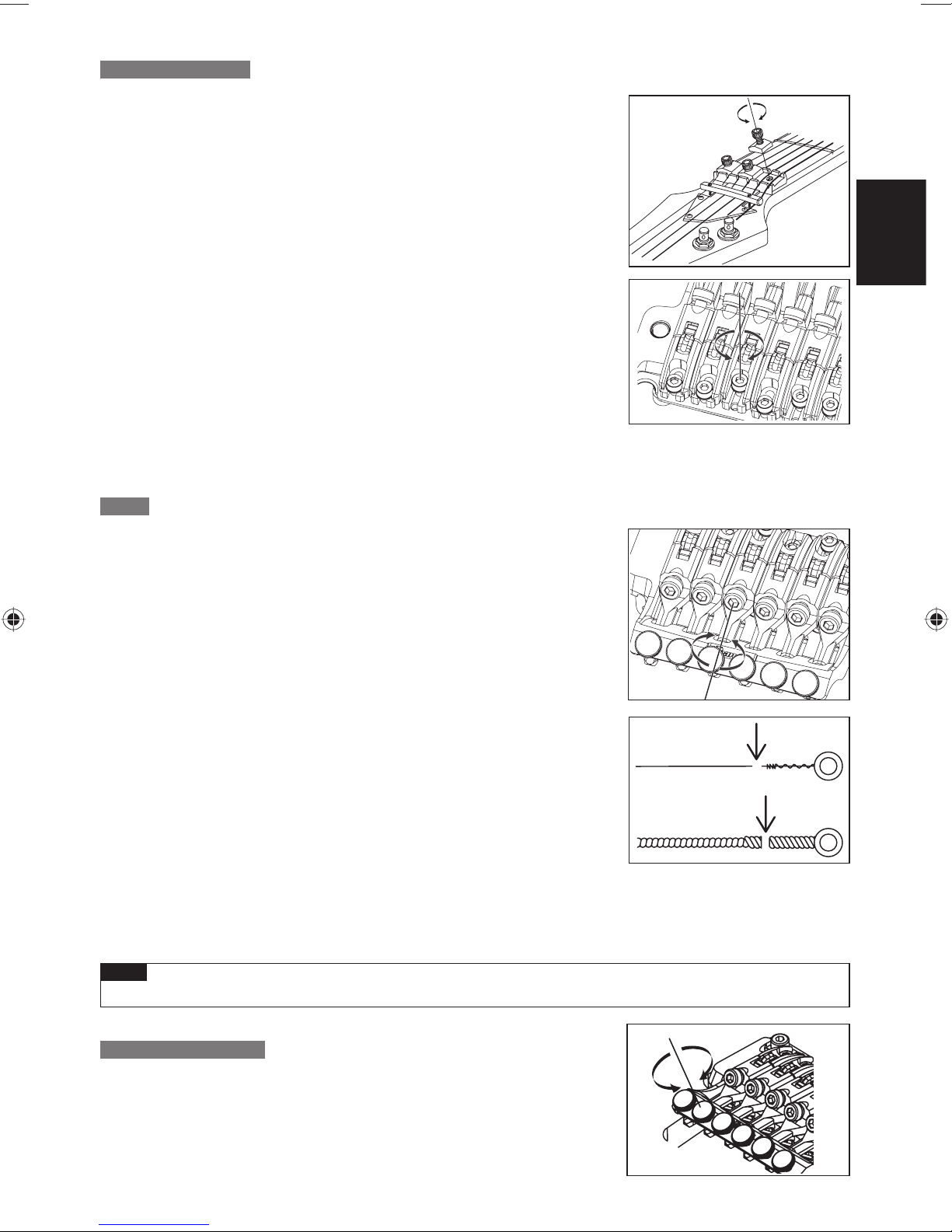
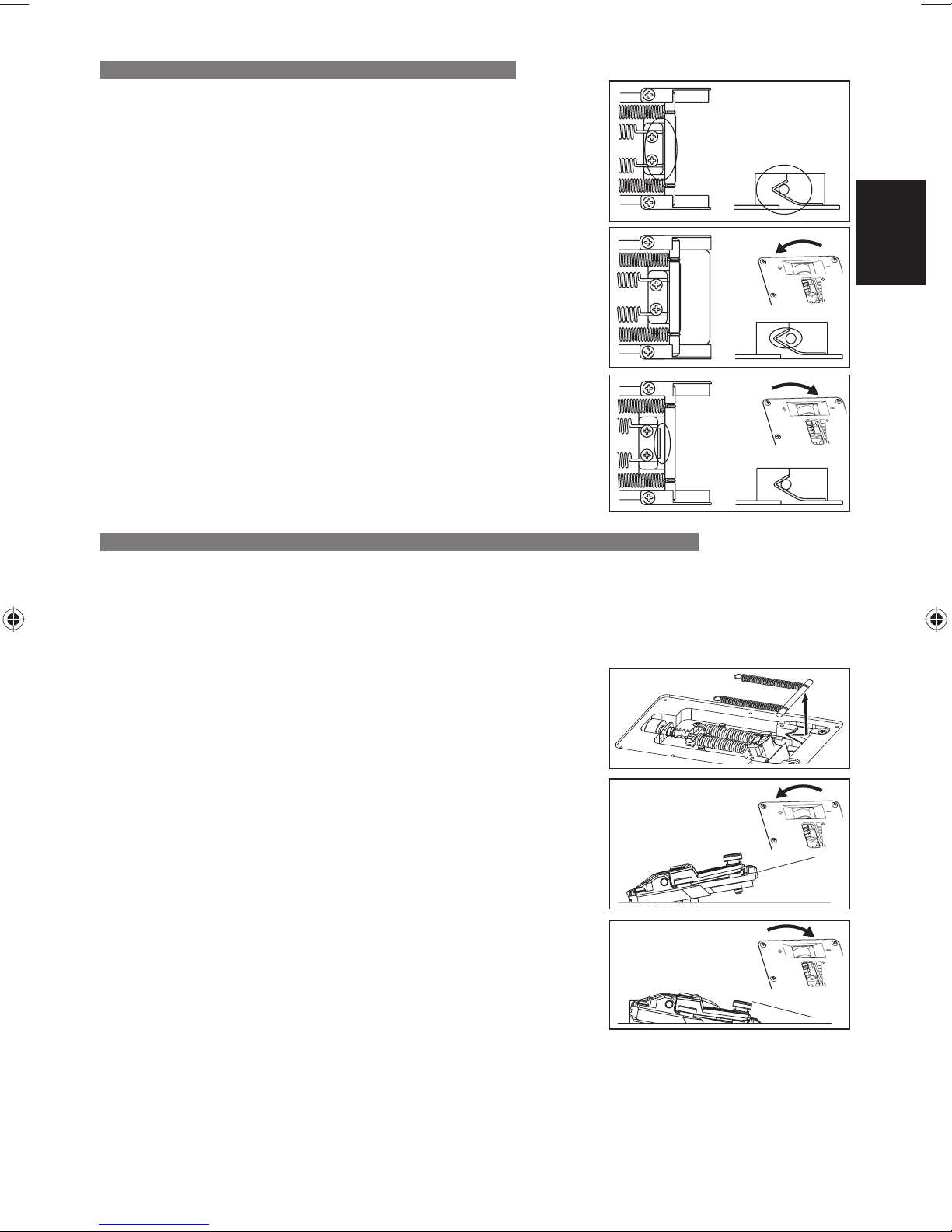
1
正しくチューニングした 状態で、トレモロの傾きを確認します。
2トレモロが前方へ傾いている場合は、ボディー裏側 のトレ モロ・スプリン
グ・カバーのスリットからプラスドライバーを挿し込み、スクリューを締
め 込んでトレ モ ロ・スプリングの張力を強くします。
3トレモロが後方へ傾いている場合は、スクリューを緩め、トレ モ ロ・スプ
リングの張力を弱めます。
トレモロの角度調整は、トレ モロ・スプリングの張力を調整するたびに弦とスプリングとの張力バランスが変化するた※
め、チューニングに影響を及ぼします。チュー ニング を繰り返しな がら調整してください。
トレモロ・スプリング
工場出荷時は、3 本 のトレ モロ・スプリングが並行に取り付けられた状態でセットアップされています。弦のゲージを変更し
たり、ダウンチューニングで使用するなど弦とトレモロ・スプリングとの張力バランスが大きく変化する場合には、トレ モ ロ・
スプリングの数や取り付け方の変更が必要になる場合があります。
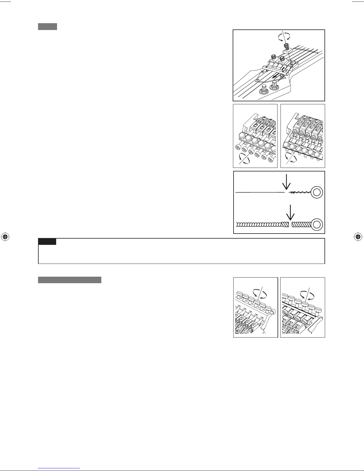
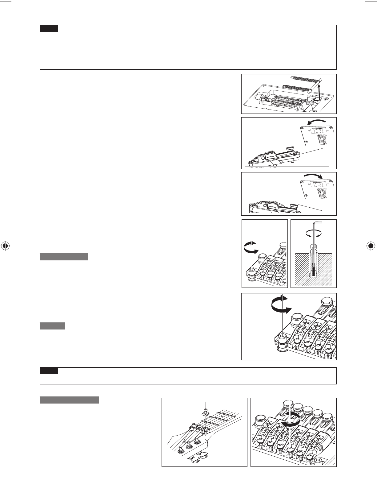
スプリングロックをプラスドライバーで取り外します。
1
2張力を強めたい場合は、外側の2本のトレモロ・スプリングを斜めに取
り付けます。
3張力を弱めたい場合は、中 央 のトレ モ ロ・スプリング を取り外します。
4 本以上のトレモロ・スプリングを装着する場合は、スプリングロックを取り付け
ているスクリュー穴を利用して取り付けます(スプリングロックは装着できなくな
ります)。
16
Page 19

ご注意
トレモロ・スプリングの着脱は弦を十分に緩めてから行ってください。また、全てのスプリングを外すとトレモ•
ロがギターから外れますのでご注意下さい。
再度トレモロを取り付ける際は、トレモロのナイフエッジをスタッドボルトの溝に確実に挿し込んだ状態でト•
レモロ・スプリングを取り付けてください。
スタッド・ロック
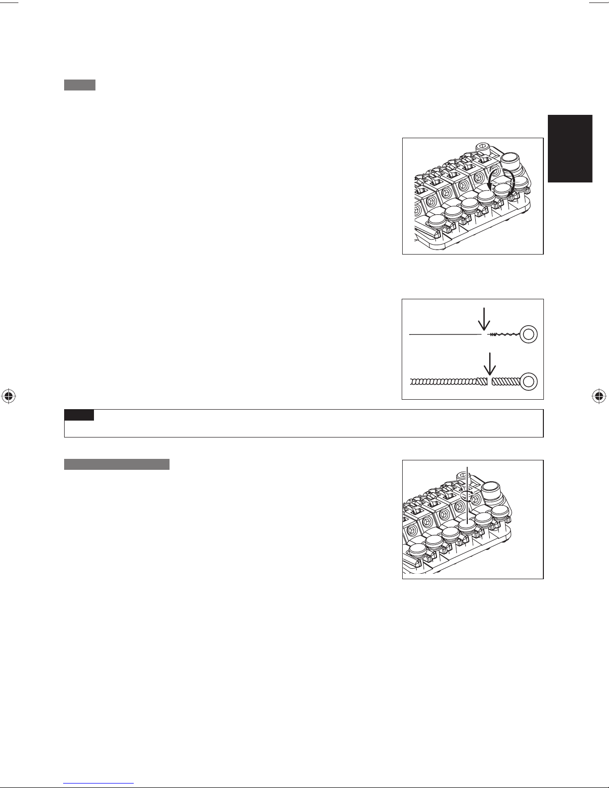
Edge/Lo-ProEdgeトレモロ・ブリッジは、スタッド・ロック機能を備えています。
1
六角レンチ(1.5mm)をスタッドボルト上部の穴から挿入します。
2スタッド・ロック・ボルトを時計方向に回し、スタッド・ロック・ボ ルト が ア
ンカーナットに接触して回らなくなるまで締め込みます。
スタッド・ロックは、スタッド・ロック・ボルトを緩めると解除されます。※
弦高調整
トレモロ本体左右のスタッドボルトを六角レンチ(4mm)で回して、トレ モ ロ 全 体
の高さを動かして弦高を調整します(各弦ごとの調整は行えません)。
日本語
ご注意
弦高調整は、スタッド・ロックが解除されていることを確認してから行ってください。•
イントネーション調整
1
ロッキング・ナットのプレッシャー・パ ッド・ボ ル ト を 六 角 レ ン チ(3mm)
で緩め、十分に弦を緩めます。
2サドル・ロック・ボ ル ト を 六 角 レ ン チ(2mm)で緩め、サドル位置を調整
します。
イントネーションの確認は、サドル・ロック・ボルトがしっかりと締まった状態※
で、正しい チューニングで 行ってください。調整が終わりましたら、サド ル・ロ
ック・ボルトとロッキング・ナットのプレッシャー・パ ッド・ボ ル ト を 締 め てくだ
さい。
17
Page 20
弦交換
1
ロッキング・ナットのプレッシャー・パ ッド・ボ ル ト を 六 角 レ ン チ(3mm)
で緩め、糸巻きから弦を 取り外します。
2トレモロ本体のストリング・ストッパー・ボ ルトを 六 角 レ ン チ(3mm)で緩
め、サドルから弦を引き抜いて取り外します。
3新しい弦は先端のボールエンド部分をニッパー等で切り落とします。
4ボールエンドを切り落とした側の弦の先端をサドルとストリング・ホ ル
ダー・ブロックとの間に挿入し、ストリング・ストッパー・ボ ルト を 締 め て
弦を固定します。
5糸巻きで弦を巻き上げ、チューニングを行います。
6チューニング完了後、ロッキング・ナットのプレッシャー・パ ッド・ボ ルト
を締めます。
全ての弦を一度に取り外すとトレモロの取り付け角度が大きく変化するた※
め、弦交換は1本ずつ行うことをお勧めします。全ての弦を一度に取り外す場
合にはトレモロの取り付け角度が大きく変化しないよう、トレモロ下部にクロ
ス等を挟んで固定するとチューニングが比較的容易に行えます。
ご注意
チューニングを行う前に、ストリング・ストッパ ー・ボルトがしっかりと締め付けられていることを確認してくだ•
さい。
EDGE
Lo-Pro EDGE
ファイン・チューニング
ロッキング・ナットで弦をロックした後でも、ファイン・チューナーによって
各弦のチューニングの微調整が行えます。
チューニングの前に、あらかじめ全てのファイン・チューニング・ボルトを可
動範囲の中央付近に調整しておくと、弦をロックした後の調整幅を広く持たせ
ることができます。
EDGE
Lo-Pro EDGE
18
Page 21
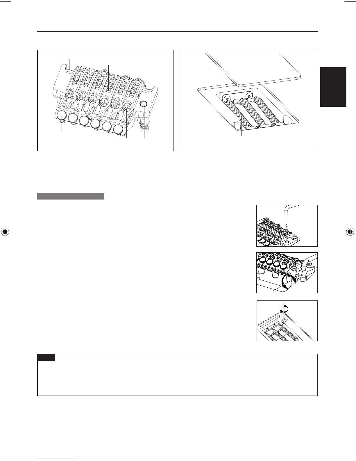
EDGEIIIトレモロ・ブリッジ
正面■ 背面■
1
3
2
1
日本語
6
1
ナイフエッジ
2
サドル・ロック・ボ ル ト
3
ストリング・ホ ル ダ ー・ブロック
4
アームソケット
トレモロアームの取り付け
1トレモロアームは挿し込み式です。ベースプレートのアームソケットに、
トレモロアームのコーナー部分を持って確実に挿し込みます。
54
5
ストリング・ストッパ ー・ボ ル ト
6
ファイン・チューニング・ボ ル ト
7
トレ モロ・スプリング
8
スプリング・ロック
7
※EGEN8に搭載されているEDGEIIIHermanLiVer.のトレモロアームはねじ込み式
です。トレモロアームをアームソケットに挿入後、回転させて締め込みます。
2トレモロアームの締め付けは、トレ モロ・ブロック側面の調整穴から、トルク調整スクリュ
ーを六角レンチ(2mm)で回して調整します。
トルク調整スクリューを時計回りに締めこむとトレモロアームの締め付けが増し、
緩めると締め付けも緩くなります。
8
3トレモロアームの高さは、ギター裏側のトレモロ・スプリング・カバーを取り外し、トレ モ
ロ・ブロック底面にある高さ調整スクリューを六角レンチ(3mm)で回して調整します。時
計回りに締め込むほど取り付け高さは高くなります。
ご注意
トレモロアームのトルク調整スクリューは、上記以外にトレモロ・ブロック下部にも設けられています。•
トレ モロ・ブロック下 部のトルク調 整スクリューは出荷時に調整されていますが、調整が必要になった場合は
トレモロ本体をギターから取り外した状態で行ってください。
トレモロアームを取り付ける前に、トルク調整スクリューに緩 みや脱 落がない事を確認してください。•
19
Page 22
トレモロの取り付け角度調整
トレモロの取り付け角度は、弦の張力とギターのボディー裏側に装着され
たトレモロ・スプリングの張力とのバランスで調整します。トレ モ ロ が ギタ
ーのボディー表面とおおよそ平行になるように調整することで、最も優れ
た性能を発揮します。
1正しくチューニングした 状態で、トレモロの傾きを確認します。
2トレモロが前方へ傾いている場合は、ボディー裏側のトレモロ・スプリング・
カバーのスリットからプラスドライバーを挿し込み、スクリューを締め込んで
トレモロ・スプリングの張力を強くします。
3トレモロが後方へ傾いている場合はスクリューを緩め、トレモロ・スプリング
の張力を弱めます。
トレモロの角度調整は、トレ モロ・スプリングの張力を調整するたびに弦とスプリングとの張力バランスが変化するた※
め、チューニングに影響を及ぼします。チュー ニング を繰り返しな がら調整してください。
トレモロ・スプリング
工場出荷時は、3 本 のトレ モロ・スプリングが並行に取り付けられた状態でセットアップされています。
弦のゲージを変更したり、ダウンチューニングで使用するなど弦とトレモロ・スプリングとの張力バランスが大きく
変化する場合には、トレ モロ・スプリングの数や取り付け方の変更が必要になる場合があります。
1スプリングロックをプラスドライバーで取り外します。
2張力を強めたい場合は、外側の2本のトレモロ・スプリングを斜めに取り付
けます。
3張力を弱めたい場合は、中央のトレモロ・スプリングを取り外します。
4 本以上のトレモロ・スプリングを装着する場合は、スプリングロックを取り
付けているスクリュー穴を利用して取り付けます(スプリングロックは装着
できなくなります)。
ご注意
トレ モロ・スプリングの着脱は弦を十分に緩めてから行ってください。また、全てのスプリングを外すとトレモロ•
がギターから外れますのでご注意下さい。
再度トレモロを取り付ける際は、トレモロのナイフエッジをスタッドボルトの溝に確実に挿し込んだ状態でトレ•
モロ・スプリングを取り付けてください。
弦高調整
トレモロ本体左右のスタッドボルトを六角レンチ(3mm)で回して、トレモロ
全体の高さを動かして弦高を調整します(各弦ごとの調整は行えません)。
20
Page 23
イントネーション調整
1ロッキング・ナットのプレッシャー・パ ッド・ボ ル ト を 六 角 レ ン チ(3mm)で緩め、
十分に弦を緩めます。
2サドル・ロック・ボ ル ト を 六 角 レ ン チ(2mm)で緩め、サドル位置を調整します。
イントネーションの確認は、サドル・ロック・ボルトがしっかりと締まった状態で、正しいチューニングで行ってください。※
調整が終わりましたら、サドル・ロック・ボルトとロッキング・ナットのプレッシャー・パ ッド・ボ ル ト を 締 め てくだ さ い 。
弦交換
日本語
1ロッキング・ナットのプレッシャー・パ ッド・ボ ル ト を 六 角 レ ン チ(3mm)で緩め、
糸巻きから弦 を取り外します。
2トレモロ本体のストリング・ストッパー・ボ ルト を 六 角 レ ン チ(3mm)で緩め、サド
ルから弦を引き抜いて取り外します。
3新しい弦は先端のボールエンド部分をニッパー等で切り落とします。
4ボールエンドを切り落とした側の弦の先端をサドルとストリング・ホ ル ダ ー・ブロ
ックとの間に挿入し、ストリング・ストッパー・ボルトを締めて弦を固定します。
5糸巻きで弦を巻き上げ、チューニングを行います。
6チューニング完了後、ロッキング・ナットのプレッシャー・パ ッド・ボ ルト を 締 め
ます。
全ての弦を一度に取り外すとトレモロの取り付け角度が大きく変化するため、弦交換は1本ずつ行うことをお勧めしま※
す。全ての弦を一度に取り外す場合にはトレモロの取り付け角度が大きく変化しないよう、トレモロ下部にクロス等を挟
んで固定するとチューニングが比較的容易に行えます。
ご注意
チューニングを行う前に、ストリング・ストッパ ー・ボルトがしっかりと締め付けられていることを確認してください。•
ファイン・チューニング
ロッキング・ナットで 弦をロックした後でも、ファイン・チューナーによって各
弦のチューニングの微調整が行えます。
チューニングの前に、あらかじめ全てのファイン・チューニング・ボ ル ト を 可 動
範囲の中央付近に調整しておくと、弦をロックした後の調整幅を広く持たせる
ことができます。
21
Page 24
EDGE-ZERO2トレモロ・ブリッジ
正面■
1
3
2
1
1 ナイフエッジ
2 サドル・ロック・ボルト
3 ストリング・ホルダー・ブロック
4 アームソケット
5 ストリング・ストッパー・ボルト
6 ファイン・チューニング・ボルト
7 メイン・スプリング
8 サブ・スプリング
9 ストッパー
: ストップ・ロッド
A トレモロ・ブロック
B スプリング調整ノブ
C トレモロ・スプリング
6
5
4
D スプリング・ロック
背面■ 1 背面■ 2
B
7
7
8
A
8
9
:
C
D
トレモロアームの取り付け
1トレモロアームはトルク調整キャップ一体型の挿し込み式です。ベースプレ
ートのア ームソ ケットに
トレモロアームを差し込みます。
2トルク調整キャップを締め、トレモロアームを固定します。トルク調整キャップ
を締め込むほど、トレモロアームの締め付けが増します。
トレモロの取り付け角度調整/ゼロ・ポイント・システムの調整
・ゼロ・ポイント・システム非搭載モデル
トレモロの取り付け角度は、弦の張力とギターのボディー裏側に装着されたトレモロ・スプリングの張力とのバラ
ンスで調整します。
トレモロがギターのボディー表面とおおよそ平行になるように調整する事で、最も優れた性能を発揮します。
22
Page 25
1正しくチューニングした 状態で、トレモロの傾きを確認します。
2トレモロが前方へ傾いている場合は、ボディー裏側のトレモロ・スプリング・カバ
ーのスリットからプラスドライバーを挿し込み、スクリューを締め込んでトレモ
ロ・スプリングの張力を強くします。
3トレモロが後方へ傾いている場合はスクリューを緩め、トレモロ・スプリングの
張力を弱めます。
トレモロの角度調整は、トレ モロ・スプリングの張力を調整するたびに弦とス※
プリングとの張力バランスが変化するため、チューニングに影響を及ぼしま
す。チューニングを繰り返しながら調整してください。
・ゼロ・ポイント・システム搭載モデル
トレモロの取り付け角度は、弦の張力とギターのボディー裏側に装着され
たゼロ・ポ イ ント・システムとのバランスで調整します。Edge-Zero2トレモ
ロ・ブリッジは、ゼロ・ポ イ ント・システムを正しく調整するとトレモロがギタ
ーのボディー表面とおおよそ平行になるように設計されており、その状態
で最も優れた性能を発揮します。
ゼロ・ポ イ ント・システムが正しく調整された状態とは、ストップ・ロッドが
トレモロ・ブ ロックと密 着し、且つストップ・ロッドがストッパーに接した状
態を指します。
日本語
1正しくチューニングした 状態で、ゼロ・ポ イ ン ト・システムを確認します。
2ストップ・ロッドがストッパーに接していない(トレ モロ・ブロックがストップ・
ロッドを押し上げている)場合は、ボディー裏側のスプリング調整ノブをプラ
ス方向 に回してメイン・スプリングの張力を強くします。
3トレ モロ・ブロックがストップ・ロッドと密着していない(トレモロが後方に傾
いている)場合は、スプリング調整ノブをマイナス方向に回してメイン・スプリ
ングの張力を弱めます。
トレモロ・スプリング/ゼロ・ポイント・システム
・ゼロ・ポイント・システム非搭載モデル
工場出荷時は、3 本 のトレ モロ・スプリングが並行に取り付けられた状態で
セットアップされています。
弦のゲージを変更したり、ダウンチューニングで使用するなど弦とトレモ
ロ・スプリングとの張力バランスが大きく変化する場合には、トレ モロ・スプ
リングの数や取り付け方の変更が必要になる場合があります。
1スプリングロックをプラスドライバーで取り外します。
2張力を強めたい場合は、外側の2本のトレモロ・スプリングを斜めに取り付
けます。
3張力を弱めたい場合は、中央のトレモロ・スプリングを取り外します。
4 本以上のトレモロ・スプリングを装着する場合は、スプリングロックを取り
付けているスクリュー穴を利用して取り付けます(スプリングロックは装着
できなくなります)。
23
Page 26
ご注意
トレ モロ・スプリングの着脱は弦を十分に緩めてから行ってください。•
また、全てのスプリングを外すとトレモロがギターから外れますのでご注意下さい。
再度トレモロを取り付ける際は、トレモロのナイフエッジをスタッドボルトの溝に確実に挿し込んだ状態でトレ•
モロ・スプリングを取り付けてください。
・ゼロ・ポイント・システム搭載モデル
ゼロ・ポ イ ント・システムを解除することで通常のフローティング・ブリッジ
としても使用できます。
ゼロ・ポ イ ント・システムを 解除したトレモロの 取り付け角度は、弦の張力
とトレ モ ロ・ブロックに装着されたメイン・スプリングの張力とのバランス
で調整します。
トレモロがギターのボディー表面とおおよそ平行になるように調整する事
で、最も優れた性能を発揮します。
1アーム・アップした状態(トレ モ ロ・ブロックがストップ・ロッドから離れた状態)
で、ストップ・ロッドとサブ・スプリングを取り外します。
2正しくチューニングした 状態で、トレモロの傾きを確認します。
3トレモロが前方へ傾いている場合は、スプリング調整ノブをプラス方向に回し
てメイン・スプリングの張力を強くします。
4トレモロが後方へ傾いている場合はスプリング調整ノブをマイナス方向に回
してメイン・スプリングの張力を弱めます。
ゼロ・ポイント・システムを解除したトレモロの角度調整は、トレモロ・スプリン※
グの張力を調整するたびに弦とスプリングとの張力バランスが変化するため、
チューニングに影響を及ぼします。チューニングを繰り返しながら調整してく
ださい。
スタッド・ロック
Edge-Zero2トレモロ・ブリッジは、スタッド・ロック機能を備えています。
1六角レンチ(2mm)をスタッドボルト上部の穴から挿入します。
2スタッド・ロック・ボルトを時計方向に回し、スタッド・ロック・ボ ル ト が ア ン
カーナットに接触して回らなくなるまで締め込みます。
スタッド・ロックは、スタッド・ロック・ボルトを緩めると解除されます。※
弦高調整
トレモロ本体左右のスタッドボルトを六角レンチ(3mm)で回して、トレモ
ロ全体の高さを動かして弦高を調整します(各弦ごとの調整は行えませ
ん)。
ご注意
弦高調整は、スタッド・ロックが解除されていることを確認してから行ってください。•
イントネーション調整
1ロッキング・ナットのプレッシャー・パ ッド・ボ
ルトを 六 角レン チ(3mm)で緩め、十分に弦
を緩めます。
2サドル・ロック・ボ ル ト を 六 角 レ ン チ(2mm)
で緩め、サドル位置を調整します。
24
Page 27
イントネーションの確認は、サドル・ロック・ボルトがしっかりと締まった状態で、正しいチューニングで行ってください。※
調整が終わりましたら、サドル・ロック・ボルトとロッキング・ナットのプレッシャー・パ ッド・ボ ル ト を 締 め てくだ さ い 。
弦交換
1ロッキング・ナットのプレッシャー・パ ッド・ボ ル ト を 六 角 レ ン チ(3mm)で緩め、糸 巻きから弦を取り外します。
2トレモロ本体のストリング・ストッパー・ボ ルト を 六 角 レ ン チ(3mm)で緩め、サド
ルから弦を引き抜いて取り外します。
3新しい弦は先端のボールエンド部分をニッパー等で切り落とします。
4ボールエンドを切り落とした側の弦の先端をサドルとストリング・ホ ル ダ ー・ブロ
ックとの間に挿入し、ストリング・ストッパー・ボルトを締めて弦を固定します。
5糸巻きで弦を巻き上げ、チューニングを行います。
6チューニング完了後、ロッキング・ナットのプレッシャー・パ ッド・ボルトを締めます。
ゼロ・ポ イ ント・システム非搭載のトレモロ・ブリッジは、全ての弦を一度に取り※
外すとトレモロの取り付け角度が大きく変化するため、弦交換は1本ずつ行うこ
とをお勧めします。全ての弦を一度に取り外す場合にはトレモロの取り付け角
度が大きく変化しないよう、トレモロ下部にクロス等を挟んで固定するとチュー
ニングが比較的容易に行えます。
日本語
ご注意
チューニングを行う前に、ストリング・ストッパ ー・ボルトがしっかりと締め付けられていることを確認してください。•
ファイン・チューニング
ロッキング・ナットで 弦をロックした後でも、ファイン・チューナーによって各弦
のチューニングの微調整が行えます。
チューニングの前に、あらかじめ全てのファイン・チューニング・ボ ル ト を 可 動
範囲の中央付近に調整しておくと、弦をロックした後の調整幅を広く持たせる
ことができます。
25
Page 28
ZRトレモロ・ブリッジ
正面■ 背面■
6
1
5
2
1 サドル・ロック・ボルト
2 ストリング・ホルダー・ブロック
3 アームソケット
4 ストリング・ストッパー・ボルト
5 ファイン・チューニング・ボルト
6イントネーション調整ボルト
トレモロアームの取り付け
3
B
7
7
8
A
4
8
9
:
7 メイン・スプリング
8 サブ・スプリング
9 ストッパー
: ストップ・ロッド
A トレモロ・ブロック
B スプリング調整ノブ
1トレモロアームはトルク調整キャップ一体型の挿し込み式です。ベースプレー
トのアームソケットにトレモロアームを差し込みます。
2トルク調整キャップを締め、トレモロアームを固定します。トルク調整キャップ
を締め込むほど、トレモロアームの締め付けが増します。
26
Page 29
トレモロの取り付け角度調整/ゼロ・ポイント・システムの調整
トレモロの取り付け角度は、弦の張力とギターのボディー裏側に装着され
たゼロ・ポ イ ント・システムとのバランスで調整します。
Z Rトレモロ・ブリッジは、ゼロ・ポ イ ント・システムを正しく調整するとトレモ
ロがギターのボディー表面とおおよそ平行になるように設計されており、
その状態で最も優れた性能を発揮します。ゼロ・ポ イ ン ト・システムが正し
く調整された状態とは、ストップ・ロッド がトレ モ ロ・ブロックと 密 着し、且つ
ストップ・ロッドがストッパーに接した状態を指します。
1正しくチューニングした状態で、ゼロ・ポイント・システムを確認しま
す。
2ストップ・ロッドがストッパーに接していない(トレモロ・ブロックが
ストップ・ロッドを押し上げている)場合は、ボディー裏側のスプリン
グ調整ノブをプラス方向に回してメイン・スプリングの張力を強くしま
す。
3トレモロ・ブロックがストップ・ロッドと密着していない(トレモロが
後方に傾いている)場合は、スプリング調整ノブをマイナス方向に回して
メイン・スプリングの張力を弱めます。
日本語
ゼロ・ポイント・システムの解除(通常のフローティング・トレモロとして使用する場合)
ゼロ・ポ イ ント・システムを解除することで通常のフローティング・ブリッジとしても使用できます。
ゼロ・ポ イ ント・システムを 解除したトレモロの 取り付け角度は、弦の張力とトレモロ・ブロックに装着されたメイ
ン・スプリングの張力とのバランスで調整します。
トレモロがギターのボディー表面とおおよそ平行になるように調整する事で、最も優れた性能を発揮します。
1アーム・アップした状態(トレ モ ロ・ブロックがストップ・ロッドから離れた状
態)で、ストップ・ロッドとサブ・スプリングを取り外しま す。
2正しくチューニングした状態で、トレモロの傾きを確認します。
3トレモロが前方へ傾いている場合は、スプリング調整ノブをプラス方向
に回してメイン・スプリングの張力を強くします。
4トレモロが後方へ傾いている場合は、スプリング調整ノブをマイナス方
向に回してメイン・スプリングの張力を弱めます。
ゼロ・ポ イ ント・システムを解除したトレモロの角度調整は、トレ モ ロ・スプリングの張力を調整するたびに弦とスプリン※
グとの張力バランスが変化するため、チューニングに影響を及ぼします。チュー ニングを繰り返しな がら調整してくださ
い。
27
Page 30
弦高調整
トレモロ本体左右のスタッドボルトを六角レンチ(3mm)で回して、トレモ
ロ全体の高さを動かして弦高を調整します(各弦ごとの調整は行えませ
ん)。
イントネーション調整
1トレモロ本体に収納されているイントネーション調整ボルトを取り外し、
サドル後部の調整穴にボルトの先端がトレモロ本体の壁に接触するまで締
め込みます。
2サドル・ロック・ボ ル ト を 六 角 レ ン チ(2mm)で緩め、イントネーション調整ボ
ルトを回してサドル位置を調整します。
イントネーションの確認は、サドル・ロック・ボルトがしっかりと締まった状態※
で、正しい チューニングで 行ってください。チュー ニングは、ロッキング・ナット
のプレッシャー・パ ッド・ボ ル ト を 六 角 レ ン チ(3mm)で緩めてから行ってくだ
さい。調整が終わりましたら、サドル・ロック・ボルトとロッキング・ナットのプ
レッシャー・パ ッド・ボ ル ト を 締 め 、イントネーション調整ボルトをトレモロ本
体に収めてください。
弦交換
1ロッキング・ナットのプレッシャー・パ ッド・ボ ル ト を 六 角 レ ン チ(3mm)で緩
め、糸 巻きから弦を取り外します。
2トレモロ本体のストリング・ストッパー・ボ ルト を 六 角 レ ン チ(3mm)で緩め、
サドルから弦を引き抜いて取り外します。
3新しい弦は先端のボールエンド部分をニッパー等で切り落とします。
ボールエンドを切り落とした側の弦の先端をサドルとストリング・ホ ル ダ ー・
4
ブロックとの間に挿入し、ストリング・ストッパ ー・ボルトを締めて弦を固定しま
す。
5糸巻きで弦を巻き上げ、チューニングを行います。
6チューニング完了後、ロッキング・ナットのプレッシャー・パ ッド・ボ ルト を 締
めます。
ご注意
チューニングを行う前に、ストリング・ストッパ ー・ボルトがしっかりと•
締め付けられていることを確認してください。
ファイン・チューニング
ロッキング・ナットで 弦をロックした後でも、ファイン・チューナーによって
各弦のチューニングの微調整が行えます。
チューニングの前に、あらかじめ全てのファイン・チューニング・ボ ル ト を 可
動範囲の中央付近に調整しておくと、弦をロックした後の調整幅を広く持
たせることができます。
28
Page 31

STD-DLトレモロ・ブリッジ
正面■ 背面■
56
4
日本語
1
1 ナイフエッジ
2 サドル・ロック・ボルト
3 ストリング・ホルダー・ブロック
4 アームソケット
トレモロアームの取り付け
1トレモロアームはトルク調整キャップ一体型の挿し込み式です。
ベースプレートのアームソケットにトレモロアームを差し込みます。
2トルク調整キャップを締め、トレモロアームを固定します。
トルク調整キャップを締め込むほど、トレモロアームの締め付けが増します。
トレモロの取り付け角度調整
123
5 ストリング・ストッパー・ボルト
6 ファイン・チューニング・ボルト
7 トレモロ・スプリング
8 スプリング・ロック
トレモロの取り付け角度は、弦の張力とギターのボディー裏側に装着され
たトレモロ・スプリングの張力とのバランスで調整します。
トレモロがギターのボディー表面とおおよそ平行になるように調整するこ
とで、最も優れた性能を発揮します。
7
8
1正しくチューニングした状態で、トレモロの傾きを確認します。
2トレモロが前方へ傾いている場合は、ボディー裏側のトレモロ・スプリン
グ・カバーのスリットからプラスドライバーを挿し込み、スクリューを
締め込んでトレモロ・スプリングの張力を強くします。
3トレモロが後方へ傾いている場合は、スクリューを緩め、トレモロ・ス
プリングの張力を弱めます。
トレモロの角度調整は、トレ モロ・スプリングの張力を調整するたびに弦とスプリングとの張力バランスが変化するた※
め、チューニングに影響を及ぼします。
チューニングを繰り返しながら調 整してください。
29
Page 32

トレモロ・スプリング
工場出荷時は、3 本 のトレ モロ・スプリングが並行に取り付けられた状態で
セットアップされています。
弦のゲージを変更したり、ダウンチューニングで使用するなど弦とトレモロ・
スプリングとの張力バランスが大きく変化する場合には、トレモロ・スプリン
グの数や取り付け方の変更が必要になる場合があります。
1張力を強めたい場合は、外側の2本のトレモロ・スプリングを斜めに取り
付けます。
2張力を弱めたい場合は、中央のトレモロ・スプリングを取り外します。
ご注意
トレ モロ・スプリングの着脱は弦を十分に緩めてから行ってください。•
また、全てのスプリングを外すとトレモロがギターから外れますのでご注意下さい。
再度トレモロを取り付ける際は、トレモロのナイフエッジをスタッドボルトの溝に確実に挿し込んだ状態でトレ•
モロ・スプリングを取り付けてください。
弦高調整
トレモロ本体左右のスタッドボルトを六角レンチ(3mm)で回して、トレモロ全体の高さを動か
して弦高を調整します(各弦ごとの調整は行えません)。
イントネーション調整
1ロッキング・ナットのプレッシャー・パッド・ボルトを六角レンチ
(3mm)で緩め、十分に弦を緩めます。
2サドル・ロック・ボルトを六角レンチ(2mm)で緩め、サドル位置を調
整します。
イントネーションの確認は、サドル・ロック・ボルトがしっかりと締ま※
った状態で、正しいチューニングで行ってください。調整が終わりまし
たら、サドル・ロック・ボルトとロッキング・ナットのプレッシャー・
パッド・ボルトを締めてください。
弦交換
1ロッキング・ナットのプレッシャー・パッド・ボルトを六角レンチ(3mm)
で緩め、糸巻きから弦を取り外します。
2トレモロ本体のストリング・ストッパー・ボルトを六角レンチ(3mm)
で緩め、サドルから弦を引き抜いて取り外します。
3新しい弦は先端のボールエンド部分をニッパー等で切り落とします。
4ボールエンドを切り落とした側の弦の先端をサドルとストリング・
ホルダー・ブロックとの間に挿入し、ストリング・ストッパー・ボルト
を締めて弦を固定します。
5糸巻きで弦を巻き上げ、チューニングを行います。
6チューニング完了後、ロッキング・ナットのプレッシャー・パッド・ボ
ルトを締めます。
全ての弦を一度に取り外すとトレモロの取り付け角度が大きく変化するた※
め、弦交換は1本ずつ行うことをお勧めします。全ての弦を一度に取り外
す場合にはトレモロの取り付け角度が大きく変化しないよう、トレモロ下
部にクロス等を挟んで固定するとチューニングが比較的容易に行えます。
30
Page 33

ご注意
チューニングを行う前に、ストリング・ストッパ ー・ボルトがしっかりと締め付けられていることを確認してください。•
ファイン・チューニング
ロッキング・ナットで 弦をロックした後でも、ファイン・チューナーによって各
弦のチューニングの微調整が行えます。チューニングの前に、あらかじめ全てのファイン・チュ
ーニング・ボルトを可動範囲の中央付近に調整しておくと、弦をロックした後の調整幅を広く持
たせることができます。
日本語
31
Page 34

SAT/FATトレモロ
ノンロッキングトレモロ
SAT/FAT/STDトレモロ
トレモロアームの取り付け
トレモロアームはトレモロプレートのアーム取り付け穴に挿し込むだけで取り付けられます。
FAT6トレモロのみトレモロアームはスクリュータイプのアームを採用しています。FAT6,STDのトレモロアームは時
計方向に回しながら装着を行います。また、反時計方向に回すことにより取り外しができます。
トレモロアームのトルク調整
1
トレモロアーム取り付け部後方のトレモロブロック上にアームのトルク調整スク
リューがあります。トレモロをダウンさせた状態で付属の1.5mm六角レンチで調整
し、アームの取り付け固さが変えられます。
弦高調整
2
トレモロ全体の高さは付属の3mm六角レンチで左右のトレモロスタッドを回し、ト
レモロプレートの高さを変えて調整します。スムースなトレモロアクションの
ために左右の高さはできるだけ均等にあるように調整してください。
3
サドルごとに弦高調整が可能なタイプのブリッジは、付属の1.5mm六角レンチでサド
ルごとに調整スクリューを回して弦高の微調整を行います。
イントネーション調整(SATPRO2,SAT10,FAT6,FAT10,STD)
5
イントネーション調整はプラスドライバーまたは六角レンチを使用して調整スク
リューを回しサドルを前後させます。
弦交換
新しい弦はギターの裏側からトレモロブロックを通して取り付けてください。
トレモロの取り付け角度調整
SAT/FATトレモロは通常、アームダウン、アップの両方向が行えるフローティ
ングと呼ばれる状態で使用します。
トレモロの取り付け角度は弦の張力と、ギターボディーの裏側に装着されたトレ
モロスプリングの張力バランスで調整します。正しくチューニングした状態で、
ギターボディー裏のトレモロスプリングカバー内のトレモロスプリングフックの
スクリューをプラスドライバーで回します。トレモロが前方へ傾きすぎている場
合は、トレモロスプリングの力が弱いため、スクリューを締め込んでスプリングを長くし
ます。逆にトレモロが後方へ傾きすぎている場合は、スプリングの力が強すぎますので、
スクリューをゆるめ、スプリングを短くします。
トレモロをギターボディーに密着させる場合、トレモロスプリングの張力を余分に強めて
おくことで、チョーキング時にも他の弦の音程変化のない、より安定した状態が得られま
す。(アームダウンは堅くなります。)
1
2
3
2
5
約3mm
トレモロ取り付け角度の調整は、トレモロスプリングの長さを変えるたびにチューニングがくるってしまいます※
ので、何度もチューニングを繰り返しながら、根気よく調整してください。
・トレモロスプリング
フローティング状態は、通常3本のスプリングを用いることが一般的です。3本のスプリングでも力が足りない場
合は、両側の2本を斜めにフックにかけることで、更に力を強めることができます。逆に3本では力が強すぎる場
合は、中央の1本を外し、両側の2本だけを使用します。また、トレモロをボディーに密着させる場合は、スプリ
ングを4本以上に増やして、完全にトレモロを固定する場合もあります。
トレモロスプリングの取り付け、取り外しは、かならず完全に弦をゆるめた状態で注意深く行ってください。
32
Page 35

日本語
33
Page 36

34
Page 37

Maintenance
ENGLISH MAINTENANCE MANUAL
ATTACHMENTS
Multi-tool Tremolo arm
PREMIUM series
Edge tremolo bridge
PREMIUM series
Edge-ZeroⅡ w/ZPS
PREMIUM series
ZR tremolo bridge w/ZPS2
PREMIUM series
Tight-End R bridge
EdgeⅢ tremolo bridge ○ ○○○○
Edge-ZeroⅡ w/ ZPS ○ ○ ○○
Edge-ZeroⅡ w/o ZPS ○ ○ ○○
FAT6 tremolo bridge ○ ○ ○○
FAT10 tremolo bridge ○ ○ ○○
FX EdgeⅢ bridge ○○○
FX EdgeⅢ-8 bridge ○○○
Gibraltar Standard bridge ○ ○ ○
Gibraltar Standard 7 bridge ○ ○ ○
SAT10 tremolo bridge ○ ○ ○○
SAT-ProⅡ tremolo bridge ○ ○ ○○
STD tremolo bridge ○
STD-DL tremolo bridge ○
Tight-End bridge ○○
Tight-Tune bridge ○ ○○
ZR tremolo bridge w/ZPS2 ○ ○ ○○
○○
○○
○○
○
1.5mm 2mm 2.5mm 3mm 4mm
Allen wrench
ENGLISH
Models equipped with DiMarzio pickups are shipped with an Allen wrench for adjusting the height of the pole pieces. ※
Seven-string guitars equipped with an Edge-Zero ※ Ⅱ tremolo bridge w/ZPS3Fe are supplied with heavy-duty
springs.
35
Page 38

GUITAR PART IDENTIFICATION
Electric Guitar Semi or Full Acoustic Guitar
TUNING MACHINE (PEG)
LOCKING NUT
FINGER BOARD
STRAP PIN
NECK PICKUP
MIDDLE
PICKUP
BRIDGE
PICKUP
TREMOLO
TREMOLO ARM
PICKUP
SELECTER
VOLUME
TONE
OUTPUT JACK
TUNING MACHINE
(PEG)
NUT
FINGER
BOARD
NECK
PICKUP
BRIDGE
PICKUP
BRIDGE
TAILPIECE
PICKUP
SELECTER
NECK
PICKUP
VOLUME
BRIDGE
PICKUP
VOLUME
BRIDGE
PICKUP
TONE
OUTPUT JACK
NECK PICKUP TONE
These illustrations show typical Ibanez models. The guitar you purchased might not match the illustration. ※
Tremolo/bridge adjustments will differ depending on the type of tremolo/bridge that is installed. ※
For details, refer to the applicable tremolo/bridge section.
For details on the controls of each model, refer to the “Controls” section (p.210). ※
36
Page 39

TUNING
When shipped from the factory, Ibanez guitars are set up using the following tunings.
1st 2nd 3rd 4th 5th 6th 7th
6-strings E4 B3 G3 D3 A2 E2 7-strings E4 B3 G3 D3 A2 E2 B1
Note that following models are set up differently.
RGD、APEX2
1st 2nd 3rd 4th 5th 6th 7th
6-strings D4 A3 F3 C3 G2 D2 7-strings D4 A3 F3 C3 G2 D2 A1
RG8、RGA8、S8、S8QM、RGIR28FE
1st 2nd 3rd 4th 5th 6th 7th 8th
D#4 A#3 F#3 C#3 G#2 D#2 A#1 F1
MTM100
1st 2nd 3rd 4th 5th 6th 7th 8th
C# G# E B F# B - -
Use a tuner or tuning fork to tune up the sound of each open string to the above frequencies. If the pitch
is higher than the above frequency, loosen the string to lower the pitch, and wind the string in small
increments to tune it up. This is an easy way to stabilize your tuning. You may need to adjust the neck or the
intonation if you tune your guitar to pitches other than those shown in these tables, or if you use strings of
other than standard gauge.
For details on adjusting the neck or the intonation, refer to the sections “NECK ADJUSTMENT” (p. 38) or
“INTONATION” (p. 38).
ENGLISH
Memo
Please note that extreme tuning or use of strings not intended for electric guitar may cause parts to break, •
and may cause unexpected injury.
STRING REPLACEMENT
Strings will deteriorate over time, causing buzzing or inaccurate pitch. Replace the strings whenever your
strings begin to rust or become discolored. We recommend that you replace all of the strings as a set at the
same time. Bent, twisted, or damaged strings will not produce the appropriate quality sound and therefore
should not be used.
Wind the string around the tuning machine post two or three times
from above, using about 5--7 cm of length and taking care that the
string does not cross itself. The strings should be replaced one
by one instead of removing all the strings at once. This is done to
avoid stress on the neck and to reduce the risk of affecting tremolo
balance.
The method for removing and installing strings attached to a tremolo/bridge will differ depending on the type of
※
tremolo/bridge.
For details, refer to the section for the tremolo/bridge installed on your guitar.
37
Page 40

STRING HEIGHT
Action refers to the distance between the frets and the string.
To measure the action, tune the guitar accurately; then place a ruler at the 14th
fret and measure the distance from the top of the fret to the bottom of the string.
In general, this distance should be 1.5--1.7 mm for the fi rst string, and 2.0 mm--
2.2 mm for the sixth string.
For a seven-string guitar, the seventh string should be at 2.2 mm--2.4 mm. For an
eight-string guitar, the eighth string should be at 2.4 mm--2.6 mm.
For strings other than those listed above, adjust the action so that the distance gradually increases from the
fi rst string toward the lowest string.
If the action is too high, the instrument will be diffi cult to play. If the action is too low, you may experience
string buzz, muted notes, or poor sustain.
If you experience string buzz or muted notes even when the action is adjusted correctly, you might need to
adjust the neck bow.
For details, refer to “Neck” (p. 38).
The method of adjusting the action will depend on the type of tremolo/bridge with which your guitar is equipped. ※
For details, refer to the appropriate tremolo/bridge section.
INTONATION
If youʼve changed string gauges or are using your
guitar with an alternative tuning, youʼll need to adjust
the string length (intonation) to ensure that the
correct pitch is sounded at all frets.
After tuning your guitar accurately, hold the guitar in
playing position and compare the pitch of each string
pressed down at the 12th fret with the pitch of the
harmonic played at the 12th fret.
If the pitch of the fretted note at the 12th fret is
lower than the harmonic at that fret, move the saddle of the tremolo/bridge forward to shorten the string.
Conversely, if the pitch of the fretted note is higher than the pitch of the harmonic, move the saddle backward
to lengthen the string.
12F
Use a tuning meter to ensure accurate intonation adjustments. ※
The method of adjusting the saddle position will differ depending on the installed model of tremolo/bridge. For ※
details, refer to the section for the tremolo/bridge thatʼs installed on your guitar.
NECK ADJUSTMENT
The neck is constantly bearing the tension of the strings, and its curvature will be subtly affected not only by
the state of tuning and the string gauge, but also by changes in temperature and humidity.
If you experience problems such as string buzz or muted notes even after the action and tuning are adjusted
correctly, you should check and adjust the curvature of the neck.
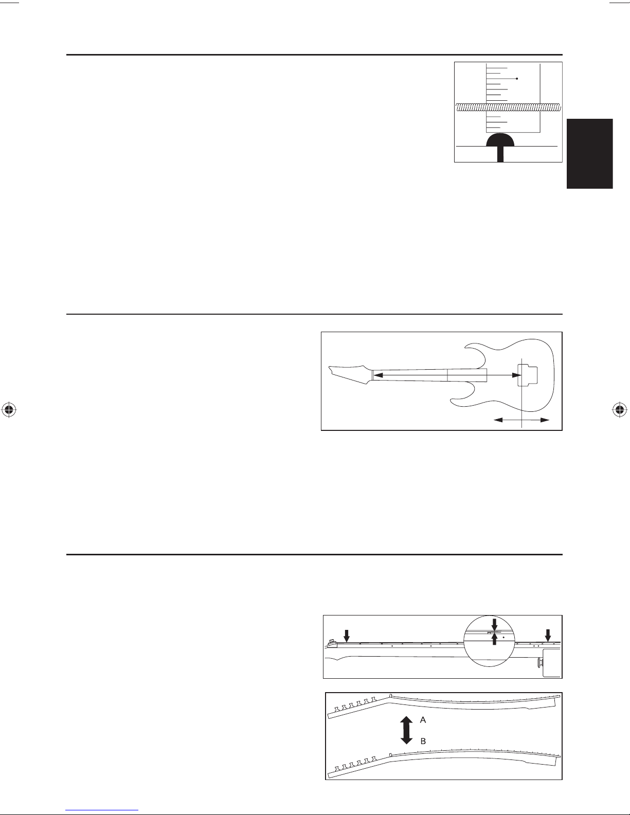
1 Check the curvature of the neck.
After tuning accurately, hold the guitar in playing
position. Then press the fi rst string at the fi rst fret and
also at the fret that is nearest to the point where the
neck joins the body, and measure the gap between the
string and fret at the eighth fret.
In the same way, measure this gap for the lowest
string, and make adjustments so that the gaps are in
the range of 0.3 mm--0.5 mm.
2 If the gap is less than 0.3 mm, use the Allen wrench
or socket wrench included with the guitar to turn the
truss rod nut located at the headstock end of the neck
in direction ʻAʼ, causing the neck curvature to be more
convex.
8th fret
38
Page 41

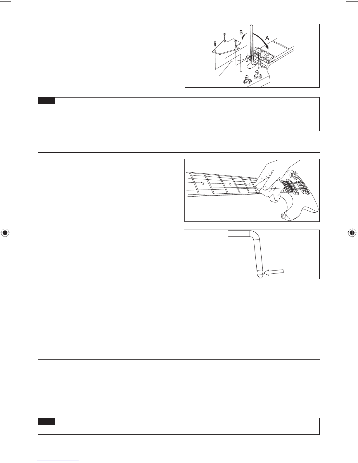
3 If the gap is greater than 0.5 mm, turn the Allen wrench
or socket wrench in direction ʻBʼ, causing the neck
curvature to be more concave.
Adjust the truss rod nut in small increments of a quarter ※
turn, checking the tuning while you do so.
Memo
You must take care when adjusting the neck.•
Forced adjustments can damage your guitar. If you are unable to adjust the neck correctly, please contact
your Ibanez authorized dealer.
CLEANING
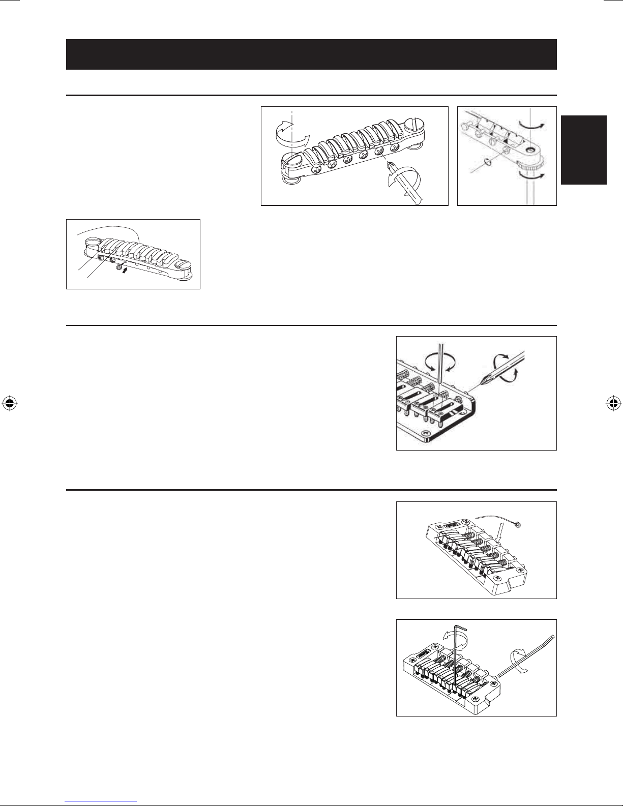
After playing, wipe sweat and oil off metal parts such
as the underside of the strings, the frets, bridge
saddles and nut. This will help to prevent rust.
Dirt or dust that adheres to metal parts may adversely
affect their function. Wipe off stubborn dirt with a soft
cloth moistened with a small amount of oil.
If the tremolo arm should squeak when turning, apply
some grease to the notch on the shorter side of the
tremolo arm.
To clean the fi nished surface, do not use volatile or
abrasive cleaning compounds; instead gently wipe
using a soft cloth with polish formulated specifi cally
for musical instruments.
ENGLISH
To clean off dirt that has adhered to an oil fi nished body or neck, use a pencil eraser, fi ne sandpaper of #1000
or fi ner grade, or #0000 steel wool. You can prevent drying by polishing once or twice a year with a colorless
furniture fi nish oil or gun oil applied to #0000 steel wool or a cloth. Unfi nished fi ngerboards should be
carefully wiped with a cloth moistened with a small amount of fi ngerboard oil or high-quality lemon oil, wiping
carefully to the edge of the frets.
BATTERY
If your guitar has a built-in pre-amplifi er or equalizer, it will be powered by a battery. Replace the battery when
you notice that the volume level has decreased or the sound has become distorted.
Some models use a 006P (9V) battery, and other models use two AA (1.5V) batteries.
Check the type of batteries used by your guitar, and replace them with the same type of batteries.
The batteries are found in the battery box located on the back of the body.
On models equipped with a battery, the output jack also functions as a power switch; inserting a plug into the
jack will turn on the power.
Memo
To prevent the battery from running down, remove the plug from the output jack if you will not be using •
it for an extended period.
39
Page 42

Guitar Bridges
ADJUSTMENT MANUAL
GIBRALTAR III (GUITAR & BASS), CB3, & FULL TUNE III, ART1, ART2
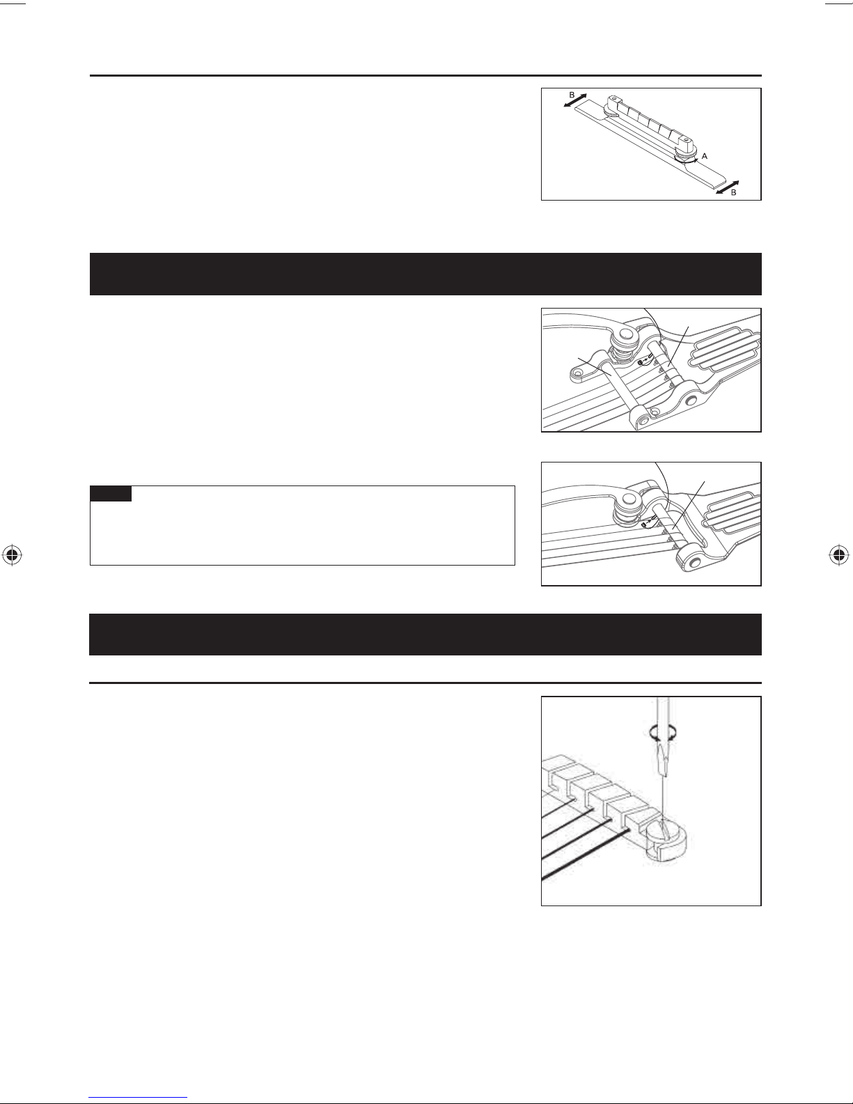
The action can be adjusted by using a slot
head (-) screwdriver to turn the adjustment
bolt at either end (A).
Intonation can be adjusted by moving the
saddle forward or backward by turning the
intonation adjustment screw (B) at the rear
of the bridge. You can use either a Phillips (+),
a fl at head (-) screwdriver, or the optional
hex wrench.
REPLACING THE STRINGS : CB3
Install strings by inserting them from the front of the bridge.
Before adjusting the action on the Gibraltar III bridge, loosen the strings suf- ※
fi ciently so that you will not need to turn the screws with excessive force, which
could damage the screw holes.
GIBRALTAR III, CB3
HARDTAIL BRIDGE
To change strings, thread the new strings through the string grommets
located on the back of the guitar and bring them up and over the
saddle. The intonation can be adjusted by adjusting the saddle forward
or backward using a Phillips (+) head screwdriver on the intonation
adjustment screw at the rear of the bridge. String height is controlled by
raising or lowering the small Allen screws using a wrench on either side of
the saddle.
(A)
(B)
(B)
FULL TUNE II,
ART1, ART2
(A)
GIBRALTER STANDARD BRIDGE (7-STRING / 8-STRING MODELS)
There are two methods to attach the strings: One method is to thread the
strings through the string grommets located on the back of the guitar, and
the other is to hook and stop the ball-end on the back of the bridge (A).
To adjust the height of the strings, use a 1.5mm hexagonal wrench to turn
and adjust the height of each saddle (B).
To adjust the intonation, use a 2.5mm hexagonal wrench to turn the
intonation adjustment screws of each saddle on the back of the bridge (C).
The adjustment method is the same for 7-string and 8-string models. ※
(A)
(B)
(C)
40
Page 43

ADJUSTABLE ARCH TOP BRIDGE
To adjust the string height, adjust the height of the entire bridge by using your
fi ngers to turn the thumb wheel screws (A) located at either side of the bridge.
(It is not possible to individually adjust the height of each string.)
To adjust the intonation, loosen the strings and move the entire bridge
forward or backward; then tune the guitar and check the intonation. Repeat
this adjustment until the intonation is correct. Take care that the bridge does
not fall over.
When replacing the strings, it is recommended that they be replaced one by
one so that the bridge does not become displaced.
Vintage Vibrato
Replace the strings one by one. Fix the ball end onto the post of the bar (B), extend the string over the bar, and then
wrap it around the peg. For a model with a retainer bar (A), VBX60/VBX80,
pass the string over the bar and then beneath the retainer bar before
wrapping it around the peg. While replacing strings, always pull the string
lightly toward the headstock and exercise care not to allow the ball-end
to go off the post. Check that the string is correctly placed on the saddle
while tuning. After completing tuning, proceed to replacement of the next
string. After fi nishing replacing all strings, carry out tuning again for the
entire unit.
Memo
Removing all strings at the same time may have a serious impact
on the state of each section of the guitar due to sudden changes
of tension imposed on the guitar. Be sure to replace the strings
one by one.
(A)
(B)
VBX60
VBS80
(B)
VBF70
Tailpieces
QUIK CHANGE TAILPIECES
ENGLISH
To adjust the height of the tailpiece, turn the stud bolt on the right and left
ends of the tailpiece with a slot head screwdriver or a coin.
To install a new string, pass it through the slot of the tailpiece and hook
the ball end into the back of the tailpiece.
(C)
QUIK CHANGE III
41
Page 44

Tight-End bridge / Tight-End R bridge (for 6-string and 7-string)
Tight-End ■ Tight-End ■
Intonation adjustment bolt
String height adjustment screw
Saddle lock bolt
ADJUSTING THE A CTION
1 Use an Allen wrench (2 mm) to loosen the saddle lock bolts.
2 To adjust the saddle height, use the Allen wrench (2 mm) to turn the
saddle height adjustment screws.
When youʼve fi nished making adjustments, tighten the saddle lock bolts. ※
Intonation adjustment bolt
String height adjustment screw
Saddle lock bolt
ADJUSTING THE INT ONATION
1 Use an Allen wrench (2 mm) to loosen the saddle lock bolts.
2 Use a Phillips screwdriver to adjust the saddle position by turning the
intonation adjustment bolt.
3 Use an Allen wrench (2 mm) to tighten the saddle lock bolts, and use
a Phillips screwdriver to lightly tighten the intonation adjustment screw
in the clockwise direction. (Tighten lightly, so as not to affect the saddle
position.)
Makesurethattheguitaristunedcorrectlybeforeyouchecktheintonation.※
STRING REPLACEMENT
To install a new string, pass it through the string stopper ferrule from the back of the guitar body.
42
Page 45

TIGHT-TUNE BRIDGE
The Tight-Tune bridge achieves the optimum level of stability and sound transference while suppressing unnecessary
vibrations by allowing each movable part of the bridge to be locked. The bridge has a stud lock function for fi xing the
bridge more securely onto the body. Furthermore, the tailpiece is equipped with a ball-end lock function to retain the
ball end so that it will not come off.
ADJUSTING THE A CTION
Loosen the locking nuts (D) on the right and left sides of the bridge unit,
and adjust the height of the bridge unit by turning the stud lock screws (E)
with a 3 mm Allen wrench. Note that it is not possible to adjust the height of
individual strings. After completing the adjustment, tighten the locking nuts.
STUD LOCK FUNCTION
After adjusting the action, turn the stud lock bolt (B) clockwise inside the
stud bolt with a 2 mm Allen wrench. Keep tightening until the stud lock bolt
contacts the anchor bolt (C) and the bolt cannot be turned any further.
Memo
When adjusting the action, be sure to fully loosen the stud lock bolt
(B) beforehand by turning it counterclockwise with a 2 mm Allen
wrench. Otherwise, damage may occur.
A
B
C
ENGLISH
ADJUSTING THE INT ONATION
Loosen the saddle lock screws (G) with a Phillips screwdriver, and turn the
intonation adjustment screw (H) with a Phillips screwdriver to adjust the
saddle position. Tune the guitar and check the intonation. Repeat these
adjustments until the required intonation is reached, and then tighten the
saddle lock screws.
Memo
A loose intonation adjustment screw (H) may cause resonance. If
this occurs, gently tighten the intonation adjustment screw , e xercising care not to allow the saddle to move.
REPLACING THE STRINGS
Insert the ball-end of the string into the slot of the tailpiece in the
direction shown by arrow (J). The ball-end lock function retains the ballend. To remove the string, pull it toward direction (K).
F
E
D
G
H
K
J
43
Page 46

Locking Bridge
FX EDGE III/FX EDGE III-8 BRIDGE
FX Edge III■
1
6
ADJUSTING THE A CTION
1 To adjust the string height, use a slotted screwdriver to turn the main
studs at the left and right of the bridge unit to adjust the height of the entire
tremolo unit. (It is not possible to adjust the height of individual strings.)
2 Use an Allen wrench (3 mm) to turn the rear studs, adjusting them so
that the bridge is approximately parallel with the surface of the guitar body.
2
5
3
1
4
1 Main stud
2 Saddle lock bolt
3 String holder block
4 String stopper bolt
5 Rear stud
6 Fine tuning bolt
As the action will change when you adjust the rear studs, it is recommended ※
that you check the fi nal action after youʼve adjusted the rear studs.
To prevent the screw holes from being damaged, loosen the strings suffi ciently before you adjust the main studs so
that you will not have to use excessive force when turning the studs.
ADJUSTING THE INT ONATION
1 Use an Allen wrench (3 mm) to loosen the pressure pad bolts of the locking
nut, and loosen the strings suffi ciently.
2 Use an Allen wrench (2 mm) to loosen the saddle lock bolt, and adjust the
saddle position.
Before checking the intonation, fi rmly tighten the saddle lock bolts and tune ※
the guitar correctly. When youʼve fi nished making adjustments, tighten the
saddle lock bolts and the pressure pad bolts of the locking nut.
44
Page 47
REPLACING THE STRINGS
1 Use an Allen wrench (3 mm) to loosen the pressure pad bolts of the
locking nut, and remove the string from the tuning peg.
2 Use an Allen wrench (3 mm) to loosen the string stopper bolt of the bridge
unit, then pull the string out of the saddle and remove it.
3 Use wire cutters to cut off the ball end of the new string.
4 Insert the tip of the string from which you cut off the ball end between the
saddle and the string holder block, and tighten the string stopper bolt to
fasten the string.
5 Wind the string onto the tuning peg, and tune it.
ENGLISH
When youʼve fi nished tuning, tighten the pressure pad bolts of the locking nut
6
Memo
.
Before you tune, make sure that the string stopper bolts are fi rmly tightened.•
FINE TUNING
Even after youʼve used the locking nuts to lock the strings, you can use the fi ne
tuners to fi ne-tune each string.
The range of adjustment after the strings are locked will be widest if you leave
all fi ne-tuning bolts near the center of their adjustable range before you tune.
45
Page 48

Locking T remolos
EDGE TREMOLO BRIDGE
Edge■ Lo-Pro Edge■
1
2
3
1
5
6
4
1
2
3
1
56
4
Rear■
1 Knife edge
2 Saddle lock bolt
3 String holder block
4 Tremolo arm socket
5 String stopper bolt
6 Fine tuning bolt
7 Tremolo spring
8 Spring lock
7
A TT ACHING THE TREMOLO ARM
1
The tremolo arm employs a snap-in/snap-out design. Hold the corner of the
tremolo arm, and press it fi rmly into the arm socket of the base plate.
46
8
Page 49

2
The tightness of the tremolo arm attachment can be adjusted by adding or
removing Tefl on washers. Using a larger number of washers will make the
attachment tighter, and removing all the washers will leave the arm free. The
Tefl on washers can be added or removed diagonally via the slit.
Memo
If the arm is no longer held fi rmly in place even after youʼve added •
Tefl on washers, replace the old Tefl on washers with new ones.
ADJUSTING THE TREMOLO A TT ACHMENT ANGLE
The tremolo attachment angle is adjusted by changing the balance between
the string tension and the tension of the tremolo springs installed on the back
of the guitar body. Youʼll obtain the optimal performance by adjusting this so
that the tremolo is approximately horizontal to the surface of the guitar body.
With the guitar tuned correctly, check the angle of the tremolo.
1
2
If the tremolo is tilted toward the front, insert a Philips screwdriver through the
slit in the tremolo spring cover on the back of the body, and tighten the screw
to increase the tension of the tremolo springs.
3
If the tremolo is tilted toward the rear, loosen the screw to decrease the tension of the tremolo springs.
The tremolo angle adjustment will affect the tuning, because the balance ※
of tension between the strings and the springs will change each time you
adjust the tension of the tremolo springs. Youʼll need to tune repeatedly
while making this adjustment.
TREMOLO SPRINGS
When the guitar is shipped from the factory, it is set up with three tremolo springs installed in parallel. If the balance of
tension between the strings and the tremolo springs has changed signifi cantly, such as when youʼve switched string
gauges or are using a dropped tuning, you may need to change the number of tremolo springs or change the way in
which they are installed.
Use a Philips screwdriver to remove the spring lock.
1
ENGLISH
2
If you want to increase the tension, install the outer two tremolo springs
diagonally.
3
If you want to decrease the tension, remove the center tremolo spring.
If you want to install four or more tremolo springs, attach them using the
screw holes that were being used to attach the spring lock. (It will no longer
be possible to attach the spring lock.)
47
Page 50

Memo
Loosen the strings suffi ciently before you install or remove tremolo springs. Be aware that if you remove •
all of the springs, the tremolo unit will detach from the guitar.
To reattach the tremolo, insert the knife edge of the tremolo securely into the groove of the stud bolts, •
and then install the tremolo springs.
STUD LOCK
The Edge/Lo-Pro Edge tremolo bridge uses a stud lock mechanism.
1
Insert an Allen wrench (1.5 mm) through the hole in the top of the stud bolt.
2
Turn the stud lock bolt clockwise, tightening it until it contacts the anchor nut
and can no longer rotate.
The stud lock will be released when you loosen the stud lock bolt. ※
ADJUSTING THE A CTION
To adjust the height of the entire tremolo unit, use an Allen wrench (4mm)
to turn the stud bolts located at the left and right of the tremolo unit. (It is not
possible to make adjustments for each string individually.)
Memo
Make sure that the stud lock is released before you adjust the action.•
ADJUSTING THE INT ONATION
Use an Allen wrench (3 mm) to loosen the pressure pad bolts of the locking
1
nut, and loosen the strings suffi ciently.
2
Use an Allen wrench (2 mm) to loosen the saddle lock bolts, and adjust the
saddle position.
Before checking the intonation, fi rmly tighten the saddle lock bolts and ※
tune the guitar correctly. When youʼve fi nished making adjustments,
tighten the saddle lock bolts and the pressure pad bolts of the locking nut.
48
Page 51

REPLACING THE STRINGS
Use an Allen wrench (3 mm) to loosen the pressure pad bolts of the locking
1
nut, and remove the string from the tuning peg.
2
Use an Allen wrench (3 mm) to loosen the string stopper bolt of the tremolo
unit; then pull the string out of the saddle and remove it.
3
Use wire cutters to cut off the ball end of the new string.
4
Insert the tip of the string from which you cut off the ball end between the
saddle and the string holder block, and tighten the string stopper bolt to fasten
the string.
5
Wind the string onto the tuning peg, and tune it.
6
When youʼve fi nished tuning, tighten the pressure pad bolts of the locking nut.
Removing all strings at the same time will cause the tremolo attachment ※
angle to change signifi cantly, so we recommend that you replace the
strings one at a time. If you remove all strings at the same time, tuning will
be easier if you wedge a piece of cloth below the tremolo to secure it so
that the tremolo attachment angle wonʼt change signifi cantly.
Memo
Before you tune, make sure that the string stopper bolts are fi rmly tightened.•
FINE TUNING
Even after youʼve used the locking nuts to lock the strings, you can use the
fi ne tuners to fi ne-tune each string.
The range of adjustment after the strings are locked will be widest if you
leave all fi ne-tuning bolts near the center of their adjustable range before you
tune.
EDGE
EDGE
Lo-Pro EDGE
ENGLISH
Lo-Pro EDGE
49
Page 52

EDGE III TREMOLO BRIDGE
Overview■ Rear■
1
3
2
1
6
1
knife edge
2
saddle lock bolt
3
string holder block
4
tremolo arm socket
A TT ACHING THE TREMOLO ARM
1 The tremolo arm employs a snap-in/snap-out design. Hold the corner of
the tremolo arm, and press it fi rmly into the arm socket of the base plate.
54
5
string stopper bolt
6
fi ne tuning bolt
7
tremolo spring
8
spring lock
7
※ The tremolo arm of the EDGE III Herman Li Ver. installed on the EGEN8 is a
screw-in type.
After inserting the tremolo arm into the arm socket, rotate it to fasten it in
place.
2 To adjust the tightness of the tremolo arm, use an Allen wrench (2 mm) to adjust the
torque adjustment screw via the adjustment hole on the side of the tremolo block.
Tightening the torque adjustment screw clockwise will make the tremolo arm
tighter; loosing the screw will make the arm looser.
3 To adjust the height of the tremolo arm, remove the tremolo spring cover on the back
of the guitar and use an Allen wrench (3 mm) to turn the height adjustment screws
located on the bottom of the tremolo block. Tightening the screws clockwise will
increase the height.
8
Memo
In addition to the one described above, the tremolo arm also has a torque adjustment screw located at •
the bottom of the tremolo block.
The torque adjustment screw at the bottom of the tremolo block is already adjusted when the guitar is
shipped from the factory; if it should require adjustment, remove the tremolo unit from the guitar and
then adjust the screw.
Before attaching the tremolo arm, make sure that the torque adjustment screw has not come loose or f allen out.•
50
Page 53

ADJUSTING THE TREMOLO A TT ACHMENT ANGLE
The tremolo attachment angle is adjusted by changing the balance
between the string tension and the tension of the tremolo springs
installed on the back of the guitar body. Youʼll obtain the optimal
performance by adjusting this so that the tremolo is approximately
horizontal to the surface of the guitar body.
1 With the guitar tuned correctly, check the angle of the tremolo.
If the tremolo is tilted toward the front, insert a Philips screwdriver through
2
the slit in the tremolo spring cover on the back of the body, and tighten the
screw to increase the tension of the tremolo springs.
3
If the tremolo is tilted toward the rear, loosen the screw to decrease the tension of the tremolo springs.
The tremolo angle adjustment will affect the tuning, because the balance of tension between the strings and the ※
springs will change each time you adjust the tension of the tremolo springs. Youʼll need to tune repeatedly while
making this adjustment.
TREMOLO SPRINGS
When the guitar is shipped from the factory, it is set up with three tremolo springs installed in parallel.
If the balance of tension between the strings and the tremolo springs has changed signifi cantly, such as when
youʼve switched string gauges or are using a dropped tuning, you may need to change the number of tremolo
springs or change the way in which they are installed.
ENGLISH
1 Use a Philips screwdriver to remove the spring lock.
2 If you want to increase the tension, install the outer two tremolo springs
diagonally.
3 If you want to decrease the tension, remove the center tremolo spring.
If you want to install four or more tremolo springs, attach them using the
screw holes that were being used to attach the spring lock. (It will no
longer be possible to attach the spring lock.)
Memo
Loosen the strings suffi ciently before you install or remove tremolo springs.•
Be aware that if you remove all of the springs, the tremolo unit will detach from the guitar.
To reattach the tremolo, insert the knife edge of the tremolo securely into the groove of the stud bolts, •
and then install the tremolo springs.
ADJUSTING THE A CTION
To adjust the height of the entire tremolo unit, use an Allen wrench (3 mm)
to turn the stud bolts located at the left and right of the tremolo unit. (It is
not possible to make adjustments for each string individually.)
51
Page 54

ADJUSTING THE INT ONATION
1 Use an Allen wrench (3 mm) to loosen the pressure pad bolts of the locking
nut, and loosen the strings suffi ciently.
2 Use an Allen wrench (2 mm) to loosen the saddle lock bolts, and adjust the
saddle position.
Before checking the intonation, fi rmly tighten the saddle lock bolts and tune the guitar correctly. When youʼve ※
fi nished making adjustments, tighten the saddle lock bolts and the pressure pad bolts of the locking nut.
REPLACING THE STRINGS
1 Use an Allen wrench (3 mm) to loosen the pressure pad bolts of the locking
nut, and remove the string from the tuning peg.
2 Use an Allen wrench (3 mm) to loosen the string stopper bolt of the tremolo
unit; then pull the string out of the saddle and remove it.
3 Use wire cutters to cut off the ball end of the new string.
4 Insert the tip of the string from which you cut off the ball end between the
saddle and the string holder block, and tighten the string stopper bolt to
fasten the string.
5 Wind the string onto the tuning peg, and tune it.
When youʼve fi nished tuning, tighten the pressure pad bolts of the locking nut.
6
Removing all strings at the same time will cause the tremolo attachment angle to change signifi cantly, so we rec- ※
ommend that you replace the strings one at a time. If you remove all strings at the same time, tuning will be easier
if you wedge a piece of cloth below the tremolo to secure it so that the tremolo attachment angle wonʼt change
signifi cantly .
Memo
Before you tune, make sure that the string stopper bolts are fi rmly tightened.•
FINE TUNING
Even after you've used the locking nuts to lock the strings, you can use
the fi ne tuners to fi ne-tune each string.
The range of adjustment after the strings are locked will be widest if you
leave all fi ne-tuning bolts near the center of their adjustable range before
you tune.
52
Page 55

EDGE-ZERO2 TREMOLO BRIDGE
Overview■
1
3
2
1
1 knife edge
2 saddle lock bolt
3 string holder block
4 tremolo arm socket
5 string stopper bolt
6 fi ne tuning bolt
7 main spring
8 sub spring
9 stopper
: stop rod
A tremolo block
B spring adjustment knob
C tremolo spring
6
5
4
D spring lock
Rear■ 1 Rear■ 2
ENGLISH
B
7
7
8
A
8
9
:
C
D
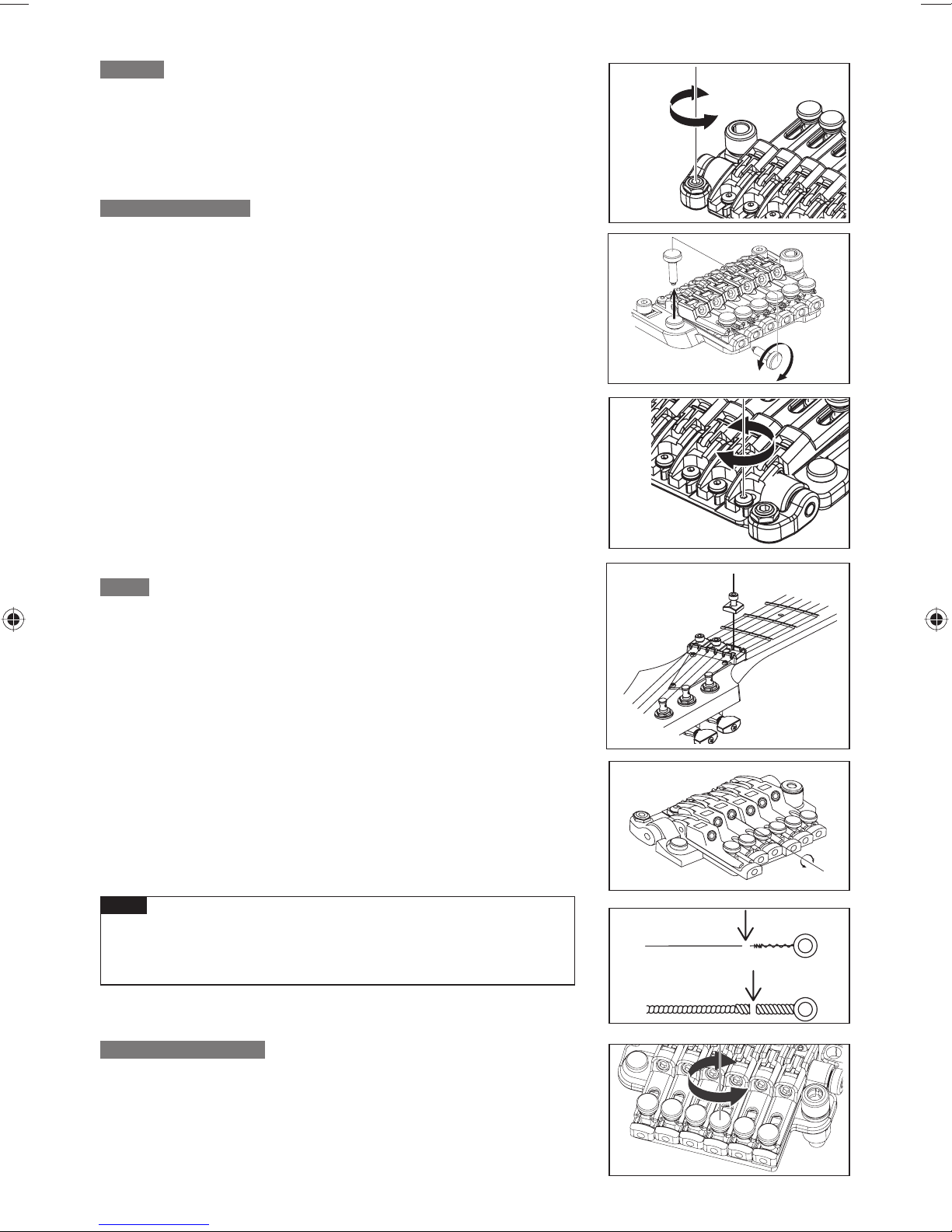
A TT ACHING THE TREMOLO ARM
1 The tremolo arm employs a one-piece snap-in design with an adjustable-
torque cap. Insert the tremolo arm into the arm socket of the base plate.
2 Tighten the torque adjustment cap to secure the tremolo arm. The tremolo
arm will become tighter as you tighten the torque adjustment cap.
TREMOLO ANGLE ADJUSTMENT / ZERO POINT SYSTEM TREMOLO
ANGLE ADJUSTMENT / ZERO POINT SYSTEM ADJUSTMENT
・ Models not equipped with the zero point system
The tremolo attachment angle is adjusted by changing the balance between the string tension and the
tension of the tremolo springs installed on the back of the guitar body. Youʼll obtain the best performance by
adjusting the tremolo arm so that it is approximately parallel with the surface of the guitar body.
53
Page 56

1 With the guitar tuned correctly, check the angle of the tremolo.
2 If the tremolo is tilted forward, insert a Philips screwdriver through the
slit in the tremolo spring cover on the back of the body, and tighten the
screws to increase the tension of the tremolo springs.
3 If the tremolo is tilted toward the rear, loosen the screws to weaken the
tension of the tremolo springs.
Because the balance of tension between the strings and the springs will ※
change each time you adjust the tension of the tremolo springs, adjusting the tremolo angle will affect the tuning. Youʼll need to tune the guitar
repeatedly while performing this adjustment.
・Models equipped with the zero point system
The angle at which the tremolo is attached is adjusted by the balance
between the tension of the strings and the zero point system installed
on the back of the guitar body. The Edge-Zero 2 tremolo bridge is
designed so that when the zero point system is correctly adjusted,
the tremolo will be approximately parallel with the surface of the guitar
body, and will perform optimally when in that state.
When the zero point system is correctly adjusted, the stop rod will be
in fi rm contact with the tremolo block and the stop rod will be touching
the stopper.
1 With the guitar tuned correctly, check the zero point system.
2 If the stop rod is not touching the stopper (i.e., if the tremolo block is
pushing up the stop rod), turn the spring adjustment knob located on the
back of the body toward the “plus” direction to tighten the main spring.
3 If the tremolo block is not in fi rm contact with the stop rod (i.e., if the
tremolo is tilted toward the rear), turn the spring adjustment knob toward
the “minus” direction to loosen the main spring.
TREMOLO SPRING / ZERO POINT SYSTEM
・Models not equipped with the zero point system
When shipped from the factory, the guitar is set up with three tremolo
springs installed in parallel.
If the balance of tension between the strings and the tremolo springs
has changed signifi cantly, such as when you switch to a different gauge
of strings or use a dropped tuning, you may need to change the number
of tremolo springs or change the way in which they are installed.
1 Use a Philips screwdriver to remove the spring lock.
2 If you want to increase the tension, install the outer two tremolo springs
diagonally.
3 If you want to decrease the tension, remove the center tremolo spring.
If you want to install four or more tremolo springs, attach them using the
screw holes that were being used to attach the spring lock. (It will no
longer be possible to attach the spring lock.)
54
Page 57

Memo
Loosen the strings suffi ciently before you install or remove tremolo springs.•
Be aware that if you remove all of the springs, the tremolo unit will detach from the guitar.
To reattach the tremolo, insert the knife edge of the tremolo securely into the groove of the stud bolts, and •
then install the tremolo springs.
・Models equipped with the zero point system
By disabling the zero point system you can use the unit as a
conventional fl oating bridge.
When the zero point system is disabled, the angle at which the tremolo
is attached will be adjusted by the balance between the tension of the
strings and the tension of the main springs attached to the tremolo
block.
For optimal performance, adjust the tremolo so that it is approximately
parallel with the surface of the guitar body.
1 While holding the arm in the upward position (i.e., with the tremolo block
away from the stop rod), remove the stop rod and the sub-spring.
2 With the guitar tuned correctly, check the angle of the tremolo.
3 If the tremolo is tilted toward the front, turn the spring adjustment knob
toward the “plus” direction to tighten the main spring.
4 If the tremolo is tilted toward the rear, turn the spring adjustment knob
toward the “minus” direction to loosen the main spring.
The tuning will be affected when you adjust the tremolo angle with the zero ※
point system disabled, because the balance between the tension of the
strings and the springs will change each time you adjust the tension of the
tremolo springs. Youʼll need to tune repeatedly while making this adjustment.
ENGLISH
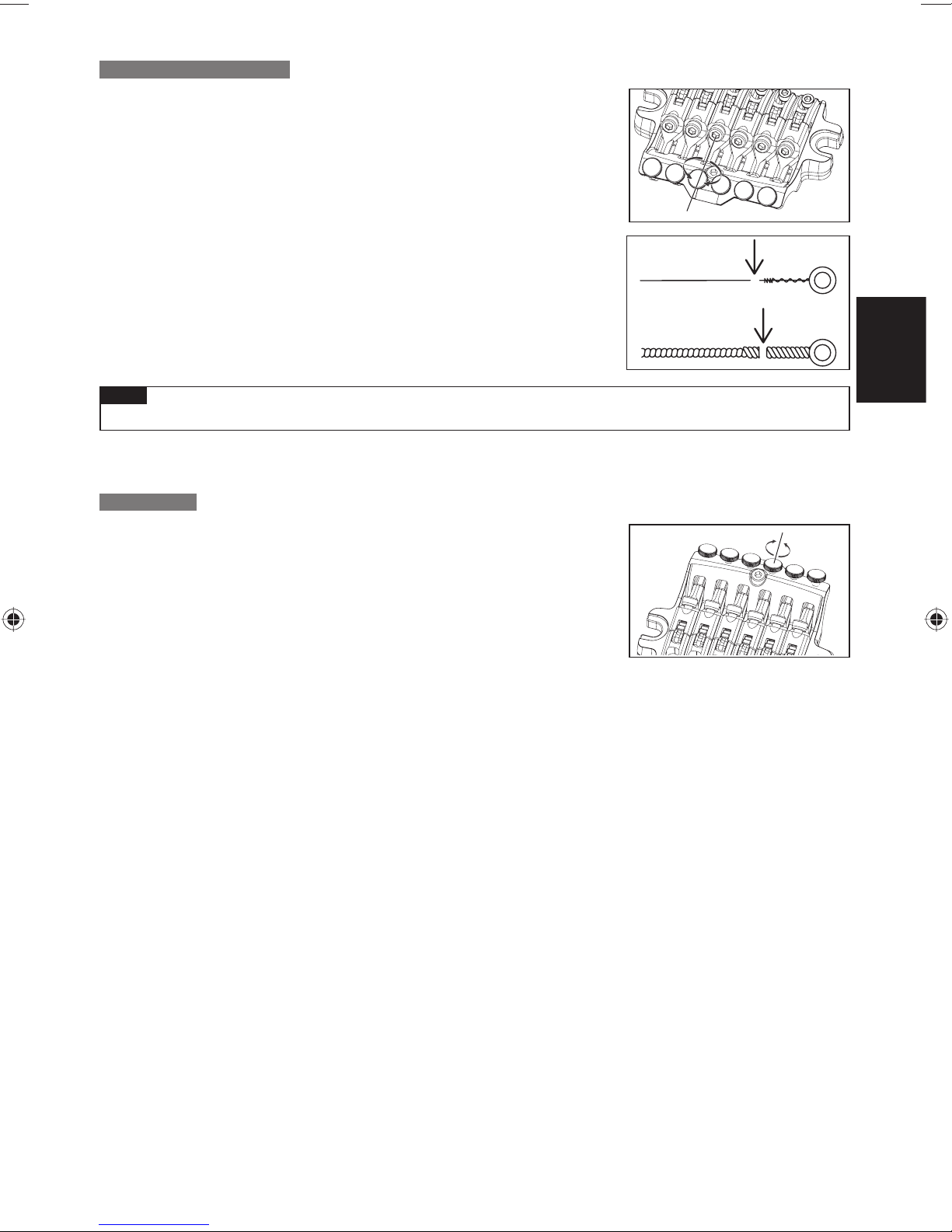
STUD LOCK
The Edge-Zero2 tremolo bridge uses a stud lock mechanism.
1
Insert an Allen wrench (2 mm) through the hole in the top of the stud bolt.
2 Turn the stud lock bolt clockwise, tightening it until it contacts the anchor
nut and can no longer rotate.
The stud lock will be released when you loosen the stud lock bolt. ※
ADJUSTING THE A CTION
To adjust the height of the entire tremolo unit, use an Allen wrench
(3 mm) to turn the stud bolts located at the left and right of the tremolo
unit. (It is not possible to make adjustments for each string individually.)
Memo
Before you tune, make sure that the string stopper bolts are fi rmly tightened.•
ADJUSTING THE INT ONATION
1 Use an Allen wrench (3 mm) to loosen the
pressure pad bolts of the locking nut, and
loosen the strings suffi ciently.
2 Use an Allen wrench (2 mm) to loosen the
saddle lock bolts, and adjust the saddle
position.
55
Page 58

Before checking the intonation, fi rmly tighten the saddle lock bolts and tune the guitar correctly. When youʼve ※
fi nished making adjustments, tighten the saddle lock bolts and the pressure pad bolts of the locking nut.
REPLACING THE STRINGS
1 Use an Allen wrench (3 mm) to loosen the pressure pad bolts of the locking nut, and remove the string from the
tuning peg.
2 Use an Allen wrench (3 mm) to loosen the string stopper bolt of the tremolo unit; then pull the string out of the
saddle and remove it.
3 Use wire cutters to cut off the ball end of the new string.
4 Insert the tip of the string from which you cut off the ball end between the
saddle and the string holder block, and tighten the string stopper bolt to
fasten the string.
5 Wind the string onto the tuning peg, and tune it.
When youʼve fi nished tuning, tighten the pressure pad bolts of the locking nut.
6
On tremolo bridges not equipped with the zero cross system, removing all ※
strings at the same time will cause the tremolo attachment angle to change
signifi cantly, so we recommend that you replace the strings one at a time. If
you remove all strings at the same time, tuning will be easier if you wedge a
piece of cloth below the tremolo to secure it so that the tremolo attachment
angle wonʼt change signifi cantly.
Memo
Before you tune, make sure that the string stopper bolts are fi rmly tightened.•
FINE TUNING
Even after youʼve used the locking nuts to lock the strings, you can use the
fi ne tuners to fi ne-tune each string.
The range of adjustment after the strings are locked will be widest if you
leave all fi ne-tuning bolts near the center of their adjustable range before
you tune.
56
Page 59

ZR TREMOLO BRIDGE
Overview■ Rear■
6
1
5
2
1 saddle lock bolt
2 string holder block
3 tremolo arm socket
4 string stopper bolt
5 fi ne tuning bolt
6 intonation adjustment bolt
A TT ACHING THE TREMOLO ARM
3
B
ENGLISH
7
7
8
A
4
7 main spring
8 sub spring
9 stopper
: stop rod
A tremolo block
B spring adjustment knob
8
9
:
1 The tremolo arm employs a one-piece snap-in design with an adjustable-
torque cap. Insert the tremolo arm into the arm socket of the base plate.
2 Tighten the torque adjustment cap to secure the tremolo arm. The tremolo
arm will become tighter as you tighten the torque adjustment cap.
57
Page 60

ANGLE ADJUSTMENT / ZERO POINT SYSTEM ADJUSTMENT
The tremolo attachment angle is adjusted by changing the balance between
the string tension and the tension of the zero point system installed on
the back of the guitar body. The ZR tremolo bridge is designed so that the
tremolo will be approximately parallel with the surface of the guitar body
when the zero point system is adjusted correctly, and will perform optimally
in this state. When the zero point system is correctly adjusted, the stop rod
will be in fi rm contact with the tremolo block and the stop rod will be touching
the stopper.
1 With the guitar tuned correctly, check the zero point system.
2 If the stop rod is not touching the stopper (i.e., if the tremolo block is
pushing up the stop rod), turn the spring adjustment knob located on the
back of the body toward the “plus” direction to tighten the main spring.
3 If the tremolo block is not in fi rm contact with the stop rod (i.e., if the
tremolo is tilted toward the rear), turn the spring adjustment knob toward
the “minus” direction to loosen the main spring.
DISABLING THE ZERO POINT SYSTEM (USING THE UNIT AS A
DISABLING THE ZERO POINT SYSTEM (USING THE UNIT AS A CONVENTIONAL FLOATING
By disabling the zero point system you can also use the unit as a conventional fl oating bridge.
When the zero point system is disabled, the angle at which the tremolo is attached will be adjusted by the balance
between the tension of the strings and the tension of the main springs attached to the tremolo block.
For optimal performance, adjust the tremolo so that it is approximately parallel with the surface of the guitar body.
1 While holding the arm in the upward position (i.e., with the tremolo block
away from the stop rod), remove the stop rod and the sub-spring.
2 With the guitar tuned correctly, check the angle of the tremolo.
3 If the tremolo is tilted toward the front, turn the spring adjustment knob
toward the “plus” direction to tighten the main spring.
4 If the tremolo is tilted toward the rear, turn the spring adjustment knob
toward the “minus” direction to loosen the main spring.
※ The tuning will be affected when you adjust the tremolo angle with the zero point system disabled, because the
balance between the tension of the strings and the springs will change each time you adjust the tension of the
tremolo springs. Youʼll need to tune repeatedly while making this adjustment.
58
Page 61

ADJUSTING THE A CTION
To adjust the height of the entire tremolo unit, use an Allen wrench
(3 mm) to turn the stud bolts located at the left and right of the tremolo
unit. (It is not possible to make adjustments for each string individually.)
ADJUSTING THE INT ONATION
1 Remove the intonation adjustment bolts stored inside the tremolo unit, and
screw them into the adjustment holes at the back of the saddle until the
tip of each bolt contacts the wall of the tremolo unit.
2 Use an Allen wrench (2 mm) to loosen the saddle lock bolt, and turn the
intonation adjustment bolt to adjust the saddle position.
Before checking the intonation, fi rmly tighten the saddle lock bolts and ※
tune the guitar correctly. Before tuning, use an Allen wrench (3 mm) to
loosen the pressure pad bolts of the locking nut. When youʼve fi nished
making adjustments, tighten the saddle lock bolts and the pressure pad
bolts of the locking nut, and store the intonation adjustment bolts inside
the tremolo unit.
ENGLISH
REPLACING THE STRINGS
1 Use an Allen wrench (3 mm) to loosen the pressure pad bolts of the lock-
ing nut, and remove the string from the tuning peg.
2 Use an Allen wrench (3 mm) to loosen the string stopper bolt of the tremo-
lo unit; then pull the string out of the saddle and remove it.
3 Use wire cutters to cut off the ball end of the new string.
4 Insert the tip of the string from which you cut off the ball end between the
saddle and the string holder block, and tighten the string stopper bolt to
fasten the string.
5 Wind the string onto the tuning peg, and tune it.
6
When youʼve fi nished tuning, tighten the pressure pad bolts of the locking nut.
Memo
Before you tune, make sure that the string stopper bolts are fi rmly •
tightened.
FINE TUNING
Even after youʼve used the locking nuts to lock the strings, you can use
the fi ne tuners to fi ne-tune each string.
The range of adjustment after the strings are locked will be widest if
you leave all fi ne-tuning bolts near the center of their adjustable range
before you tune.
59
Page 62

STD-DL TREMOLO BRIDGE
Overview■ Rear■
56
4
7
1
1 knife edge
2 saddle lock bolt
3 string holder block
4 tremolo arm socket
A TT ACHING THE TREMOLO ARM
1 The tremolo arm employs a one-piece snap-in design with an adjustable-torque cap.
Insert the tremolo arm into the arm socket of the base plate.
2 Tighten the torque adjustment cap to secure the tremolo arm.
The tremolo arm will become tighter as you tighten the torque adjustment cap.
ADJUSTING THE TREMOLO A TT ACHMENT ANGLE
123
5 string stopper bolt
6 fi ne tuning bolt
7 tremolo spring
8 spring lock
The tremolo attachment angle is adjusted by changing the balance
between the string tension and the tension of the tremolo springs
installed on the back of the guitar body.
Youʼll obtain the optimal performance by adjusting this so that the
tremolo is approximately horizontal to the surface of the guitar body.
8
1 With the guitar tuned correctly, check the angle of the tremolo.
2 If the tremolo is tilted toward the front, insert a Philips screwdriver through
the slit in the tremolo spring cover on the back of the body, and tighten the
screw to increase the tension of the tremolo springs.
If the tremolo is tilted toward the rear, loosen the screw to decrease the ten-
3
sion of the tremolo springs.
The tremolo angle adjustment will affect the tuning, because the balance of tension between the strings and the ※
springs will change each time you adjust the tension of the tremolo springs. Youʼll need to tune repeatedly while
making this adjustment.
60
Page 63

TREMOLO SPRINGS
When the guitar is shipped from the factory, it is set up with three tremolo
springs installed in parallel.
If the balance of tension between the strings and the tremolo springs has
changed signifi cantly, such as when youʼve switched string gauges or are
using a dropped tuning, you may need to change the number of tremolo
springs or change the way in which they are installed.
1 If you want to increase the tension, install the outer two tremolo springs
diagonally.
2 If you want to decrease the tension, remove the center tremolo spring.
Memo
Loosen the strings suffi ciently before you install or remove tremolo springs.•
Be aware that if you remove all of the springs, the tremolo unit will detach from the guitar.
To reattach the tremolo, insert the knife edge of the tremolo securely into the groove of the stud bolts, •
and then install the tremolo springs.
ADJUSTING THE A CTION
To adjust the height of the entire tremolo unit, use an Allen wrench (3mm) to turn the stud
bolts located at the left and right of the tremolo unit. (It is not possible to make adjustments
for each string individually.)
ADJUSTING THE INT ONATION
1 Use an Allen wrench (3 mm) to loosen the pressure pad bolts of the locking
nut, and loosen the strings suffi ciently.
2 Use an Allen wrench (2 mm) to loosen the saddle lock bolts, and adjust
the saddle position.
ENGLISH
Before checking the intonation, fi rmly tighten the saddle lock bolts and ※
tune the guitar correctly. When youʼve fi nished making adjustments,
tighten the saddle lock bolts and the pressure pad bolts of the locking nut.
REPLACING THE STRINGS
1 Use an Allen wrench (3 mm) to loosen the pressure pad bolts of the locking
nut, and remove the string from the tuning peg.
2 Use an Allen wrench (3 mm) to loosen the string stopper bolt of the
tremolo unit; then pull the string out of the saddle and remove it.
3 Use wire cutters to cut off the ball end of the new string.
4 Insert the tip of the string from which you cut off the ball end between the
saddle and the string holder block, and tighten the string stopper bolt to
fasten the string.
5 Wind the string onto the tuning peg, and tune it.
When youʼve fi nished tuning, tighten the pressure pad bolts of the locking nut
6
Removing all strings at the same time will cause the tremolo attachment ※
angle to change signifi cantly, so we recommend that you replace the
strings one at a time. If you remove all strings at the same time, tuning will
be easier if you wedge a piece of cloth below the tremolo to secure it so
that the tremolo attachment angle wonʼt change signifi cantly.
Memo
.
Before you tune, make sure that the string stopper bolts are fi rmly tightened.•
FINE TUNING
Even after youʼve used the locking nuts to lock the strings, y ou can use
the fi ne tuners to fi ne-tune each string.
The range of adjustment after the strings are locked will be widest if you lea ve all fi ne-tuning
bolts near the center of their adjustable range before you tune.
61
Page 64

Non Locking Tremolo
F A T/SA T/STD TREMOLO
TREMOLO ARM INSTALLATION
The tremolo arm can be inserted and removed very easily. Insert the arm
into the armhole on the tremolo base plate. Pull up on the arm to remove it.
TREMOLO ARM ADJUSTMENT (SAT PRO2)
To adjust the height of the arm, remove the tremolo spring cover from
the back of the guitar, and use a 3 mm Allen wrench to turn the height
adjustment screw attached to the bottom of the tremolo block. Tightening this
in the clockwise direction will raise the height.
ARM ROTATION TORQUE
The rotation torque of the arm can be adjusted by raising the tremolo and
inserting a 1.5mm Allen wrench in the screw (A) on the tremolo block,
Turning this screw clockwise will tighten the arm torque and turning the
screw counter clockwise will loosen the arm torque.
ADJUSTING THE STRING HEIGHT (SAT PRO2)
To adjust the action of each string, use a 1.5 mm Allen wrench to turn the screw on the
saddle (C). The overall height can be adjusted on either side of the SAT PRO2 tremolo
unit. To adjust the height, use a 3 mm Allen wrench to turn the stud (D) located on
either side of the unit. Use caution when adjusting the height of the entire tremolo unit;
adjust both sides to the same height to ensure optimum tremolo operation.
ADJUSTING THE STRING HEIGHT (FAT10/SAT10)
The height adjustment of the tremolo can be
raised or lowered by adjusting the pivot studs
(C)
(C) that the tremolo mounts on. These are
located at either side of the front of the bridge.
Clockwise lowers the tremolo and counter
clockwise raises the tremolo.
FAT10
INTONATION ADJUSTMENT (SAT PRO2)
To adjust the intonation, use a 1.5 mm Allen wrench to turn the screw
located at the rear of the saddle (E). Turn the screw clockwise to move the
saddle toward the rear, or counter-clockwise to move the saddle forward.
(A)
(C)
(D)
(E)
(C)
SAT10
(C)
(D)
(E)
SAT PRO2
62
Page 65

INTONATION ADJUSTMENT (FAT10/SAT10)
The intonation can be adjusted
by adjusting the saddle forward
or backward using a Phillips (+)
head screwdriver on the intonation
adjustment screw at the rear of the
bridge.
FAT10 SAT10
ADJUSTING THE INTONATION & THE STRING HEIGHT (FAT 6/STD)
The intonation can be adjusted by adjusting the saddle forward or
backward using a philips(+) head adjustment screw at the rear of the
bridge. String height is controlled by raising or lowering the small allen
screws using a wrench on either side of the saddle.
REPLACING THE STRINGS
To replace strings, thread the new strings through the string holes
located on the back of the guitar. The strings are then threaded through
the tremolo block and up and over the saddle.
ENGLISH
FAT/SAT (EXPECT FAT6) ADJUSTING THE TREMOLO SPRING
A standard tremolo can be adjusted so that the pitch can be raised
when the tremolo arm is pulled up to loosen the tremolo springs located
under the tremolo cavity on the back of the guitar. One disadvantage of
this procedure is that it can cause the pitch to go sharp if string breaks.
To remedy this, adjust the tremolo plate so it sits fl ush on the body by
tightening the tremolo springs. Choose the number and placement of
the tremolo springs according to the string gauge and the
tremolo adjustment .
Floating PARALLEL
63
Page 66

Wartung
DEUTSCH WARTUNGS- UND PFLEGEHINWEISE
ANBAUTEN
Multitool Tremolohebel
PREMIUM-Serie Edge-Tremolosteg
PREMIUM-Serie Edge-Zero II
mit ZPS
PREMIUM-Serie ZR-Tremolosteg mit ZPS2
PREMIUM-Serie Tight-EndR-Steg
Edge-III-Tremolosteg ○ ○○○○
Edge-Zero II mit ZPS ○ ○ ○○
Edge-Zero II ohne ZPS ○ ○ ○○
FAT6-Tremolosteg ○ ○ ○○
FAT10-Tremolosteg ○ ○ ○○
FX-Edge-III-Steg ○○○
FX-Edge-III-8-Steg ○○○
Gibraltar Standardsteg ○ ○ ○
Gibraltar Standard 7-Steg ○ ○ ○
SAT10-Tremolosteg ○ ○ ○○
SAT-Pro-II-Tremolosteg ○ ○ ○○
STD-Tremolosteg ○
STD-DL-Tremolosteg ○
Tight-End-Steg ○○
Tight-Tune-Steg ○ ○○
ZR-Tremolosteg mit ZPS2 ○ ○ ○○
○○
○○
○○
○
1.5mm 2mm 2.5mm 3mm 4mm
Inbusschlussel
Modelle, die mit DiMarzio-Tonabnehmern ausgestattet sind, werden mit einem Inbusschlüssel zur Höheneinstellung ※
der Polkerne geliefert.
Siebensaitige Gitarren, die mit einem Edge-Zero-II-Tremolosteg mit ZPS3Fe ausgestattet sind, werden mit hoch- ※
belastbaren Federn ausgeliefert.
64
Page 67

IDENTIFIKATION DER GITARRENTEILE
E-Gitarre Halb- oder Vollakustische Gitarre
MECHANIK (WIRBEL)
KONTERMUTTER
GRIFFBRETT
TRAGRIEMEN-STIFT
NECK PICKUP
HALS-PICKUP
MITTEL-PICKUP
TREMOLO
TREMOLOHEBEL
PICKUP-WÄHLER
VOLUME
(Lautstärke)
KLANG
AUSGANGSBUCHSE
MECHANIK (WIRBEL)
MUTTER
GRIFFBRETT
HALS-PICKUP
BRIDGE
PICKUP
BRIDGE
SAITENHALTER
HALS-PICKUP KLANG
DEUTSCH
PICKUPWÄHLER
HALS-PICKUP
LAUTSTÄRKE
BRIDGEPICKUP
LAUTSTÄRKE
BRIDGEPICKUP KLANG
AUSGANGSBUCHSE
Diese Abbildungen zeigen typische Modelle von Ibanez. Es ist evtl. nicht genau die von Ihnen erworbene Gitarre ※
abgebildet.
Die Einstellungen von Tremolo und Steg hängen von der Art des montierten Tremolos/Stegs ab. ※
Näheres fi nden Sie im entsprechenden Abschnitt zu Tremolo/Steg.
Näheres zu den Einstellmöglichkeiten der einzelnen Modelle fi nden Sie im Abschnitt ※
„CONTROLS (Einstellelemente)“ (S. 210).
65
Page 68

STIMMEN
Bei Auslieferung ab Werk wurden die Ibanez-Gitarren mit den folgenden Stimmungen versehen.
1. 2. 3. 4. 5. 6. 7.
6-Saitige E4 B3 G3 D3 A2 E2 7-Saitige E4 B3 G3 D3 A2 E2 B1
Note that following models are set up differently.
RGD, APEX2
6-Saitige D4 A3 F3 C3 G2 D2 7-Saitige D4 A3 F3 C3 G2 D2 A1
RG8, RGA8, S8, S8QM, RGIR28FE
1. 2. 3. 4. 5. 6. 7.
D#4 A#3 F#3 C#3 G#2 D#2 A#1 F1
MTM100
1. 2. 3. 4. 5. 6. 7.
C# G# E B F# B - -
Verwenden Sie ein Stimmgerät oder eine Stimmgabel, um die Tonhöhe jeder offenen Saite auf die oben
angegebenen Frequenzen einzustellen. Wenn die Tonhöhe über der angegebenen Frequenz liegt, lösen
Sie die Saite, um die Tonhöhe ein gutes Stück zu senken, und spannen Sie die Saite in kleinen Schritten,
um sie wieder heraufzustimmen. Auf diese Weise erhalten Sie eine möglichst stabile Stimmung. Sie
müssen evtl. den Hals oder die Intonation verändern, wenn Sie die Gitarre auf andere als die in diesen
Tabellen angegebenen Tonhöhen stimmen möchten oder wenn Sie Saiten mit anderen Stärken als den
Standardstärken verwenden.
Näheres zum Einstellen des Halses oder der Intonation erfahren Sie in den Abschnitten „EINSTELLEN
DES HALSES“ (S. 67) und „INTONATION“ (S. 67).
1. 2. 3. 4. 5. 6. 7.
8.
8.
Hinweis
Beachten Sie, dass durch extreme Stimmungen oder Verwendung von Saiten, die nicht für die E-Gitarre •
geeignet sind, Teile brechen und unerwartete Verletzungen verursacht werden können.
ERSETZEN VON SAITEN
Saiten altern mit der Zeit und verursachen Schnarrtöne oder lassen sich nicht mehr richtig stimmen.
Ersetzen Sie die Saiten, sobald sie beginnen zu rosten oder sich zu verfärben. Wir empfehlen Ihnen, den
kompletten Satz Saiten gleichzeitig zu wechseln. Verbogene, verdrehte oder beschädigte Saiten erzielen
keinen hochwertigen Sound und sollten daher nicht verwendet werden.
Wickeln Sie die Saite zwei- bis dreimal von oben um den
Wirbelkörper, indem Sie 5–7 cm der Saitenlänge verwenden, und
achten Sie darauf, dass die Windungen sich nicht überkreuzen. Sie
sollten jeweils nur eine Saite austauschen, anstatt alle Saiten auf
einmal zu lösen. Dies vermeidet eine Überlastung des Halses und
eine Beeinträchtigung der Tremolobalance.
Die Vorgehensweise beim Aus- und Einfädeln der Saiten an einem Tremolo/Steg hängt von der Art des Tremolos
※
bzw. Stegs ab. Näheres erfahren Sie im Abschnitt über das an Ihrer Gitarre installierte Tremolo bzw. deren Steg.
66
Page 69

SAITENHOEHE
Die Saitenlage („Action“) bezeichnet den Abstand zwischen den Bünden und der Saite.
Um die Saitenlage zu messen, stimmen Sie die Gitarre genau; platzieren Sie ein
Lineal am 14. Bund und messen Sie den Abstand von der Oberkante des Bundes
bis zur Unterkante der Saite. Generell sollte der Abstand bei der ersten Saite
1,5–1,7 mm und bei der sechsten Saite 2,0–2,2 mm betragen. Bei einer 7-saitigen
Gitarre sollte die siebte Saite einen Abstand von 2,2–2,4 mm aufweisen. Bei einer
8-saitigen Gitarre sollte die achte Saite einen Abstand von 2,4–2,6 mm haben.
Bei Anderen als den aufgeführten Saiten stellen Sie die Saitenlage so ein,
dass der Abstand schrittweise von der ersten Saite bis zur tiefsten ansteigt. Ist die Saitenlage zu hoch, ist
das Instrument schwer zu spielen. Ist die Saitenlage zu niedrig, schnarren die Saiten, werden abgedämpft
oder klingen schneller aus. Wenn Saiten schnarren oder abgedämpft werden, obwohl die Saitenlage richtig
eingestellt ist, müssen Sie eventuell die Halskrümmung einstellen.
Näheres lesen Sie unter „EINSTELLEN DES HALSES“ (S. 67).
Die Einstellmethode für die Saitenlage hängt von der Art des Tremolos/Stegs Ihrer Gitarre ab. Näheres fi nden Sie ※
im entsprechenden Abschnitt zu Tremolo/Steg.
INTONATION
Wenn Sie die Saitenstärke verändert haben oder Ihre
Gitarre auf eine abweichende Stimmung gestimmt
haben, müssen Sie die Saitenlänge einstellen
(intonieren), um sicherzustellen, dass auf allen
Bünden die jeweils richtige Tonhöhe gespielt wird.
Nachdem Sie Ihre Gitarre genau gestimmt haben,
halten Sie sie in Spielposition und vergleichen Sie die
Tonhöhe jeder Saite, gespielt auf dem 12. Bund, mit
der Tonhöhe des Obertons in Höhe des 12. Bundes.
Wenn die Tonhöhe der auf dem 12. Bund gespielten Note niedriger ist als der Oberton in Nähe dieses
Bundes, schieben Sie den Sattel am Tremolo/Steg nach vorne, sodass die Saite verkürzt wird. Wenn
hingegen die Tonhöhe der auf dem 12. Bund gespielten Note höher ist als der Oberton in Nähe dieses
Bundes, schieben Sie den Sattel am Tremolo/Steg nach hinten, sodass die Saite verlängert wird.
12F
DEUTSCH
Verwenden Sie ein Stimmgerät, um eine genaue Intonation einstellen zu können. ※
Die Einstellmethode für die Sattelposition hängt von der Art des montierten Tremolos/Stegs ab. Näheres erfahren ※
Sie im Abschnitt über das an Ihrer Gitarre installierte Tremolo bzw. deren Steg.
EINSTELLEN DES HALSES
Der Hals steht andauernd unter der Spannung der aufgezogenen Saiten, und dessen Krümmung ändert sich
fortwährend nicht nur durch die Stimmung und die Saitenstärke, sondern auch durch Schwankungen von
Temperatur und Feuchtigkeit.
Wenn Sie Probleme mit schnarrenden oder abgedämpften Saiten haben, obwohl Saitenlage und Stimmung
richtig eingestellt wurden, prüfen Sie die Halskrümmung und stellen Sie sie ggf. ein.
1 Prüfen Sie die Halskrümmung.
Nachdem Sie die Gitarre genau gestimmt haben,
halten Sie sie in Spielposition. Drücken Sie dann die
erste Saite am ersten Bund sowie den Bund, der dem
Punkt am nächsten ist, an dem der Hals in den Korpus
läuft, und messen Sie den Abstand zwischen der Saite
und dem achten Bund.
Messen Sie diesen Abstand ebenso bei der tiefsten
Saite , und stellen Sie den Hals so ein, dass die
Abstände im Bereich zwischen 0,3–0,5 mm liegen.
2 Wenn der Abstand weniger als 0,3 mm beträgt, ver-
wenden Sie den mit der Gitarre gelieferten Inbus- oder
Steckschlüssel, um die Halsstabmutter am Kopfende
des Halses in Richtung ‚Aʻ zu drehen, sodass die Halskrümmung sich mehr Richtung konvex ändert.
8. Bund
67
Page 70

3
Wenn der Abstand mehr als 0,5 mm beträgt, drehen
Sie den Inbus- oder Steckschlüssel in Richtung ‚Bʻ, sodass
die Halskrümmung sich mehr Richtung konkav ändert.
Stellen Sie die Halsstabmutter in kleinen Schritten von ※
einer Vierteldrehung ein, und prüfen Sie währenddessen die Stimmung.
Hinweis
Beim Einstellen des Halses sollten Sie vorsichtig sein.•
Wenn Sie den Hals nicht richtig einstellen können, wenden Sie sich bitte an Ihren authorisierten IbanezHändler.
REINIGEN
Wischen Sie nach dem Gitarrespiel Schweiß und Fett
von Metallteilen wie der Unterseite der Saiten, den
Bünden, den Satteln, dem Steg und der
Einstellschraube ab. Dadurch verhindern Sie
Korrosion. Schmutz oder Staub an Metallteilen können
deren Funktion beeinträchtigen.
Wischen Sie hartnäckigen Schmutz mit einem mit ein
wenig Öl getränkten Tuch ab.
Falls der Tremolohebel bei Betätigung quietschen
sollte, geben Sie etwas Fett in die Kerbe an der
kürzeren Seite des Tremolohebels.
Zum Reinigen der lackierten Oberfl ächen sollten
Sie keine löse- oder scheuermittelhaltigen
Reinigungsmittel verwenden; wischen Sie diese
Flächen stattdessen mit einem weichen Tuch und
einer speziellen Politur für Musikinstrumente sauber.
Um Schmutz zu entfernen, der einem ölbehandelten Korpus oder Hals anhaftet, verwenden Sie ein
Radiergummi, feines Sandpapier der Körnung 1000 oder feiner oder Stahlwolle mit dem Feinheitsgrad Nr.
0000. Einem Austrocknen des Holzes können Sie vorbeugen, indem Sie ein- bis zweimal im Jahr die Gitarre
mit farbloser Möbelpolitur oder Waffenöl mithilfe von Stahlwolle Nr. 0000 oder eines Tuches einreiben.
Unbehandelte Griffbretter sollten sorgfältig bis heran an die Bünde mit einem Tuch mit einer kleinen Menge
Griffbrettöl oder Zitronenöl guter Qualität abgerieben werden.
BATTERIE
Wenn Ihre Gitarre einen eingebauten Vorverstärker oder Equalizer besitzt, werden diese durch eine Ersetzen
Sie die Batterie, sobald Sie bemerken, dass die Lautstärke abgenommen hat oder der Ton verzerrt ist.
Einige Modelle verwenden eine Batterie des Typs 006P (9 V), andere verwenden zwei AA-Batterien (1,5 V).
Prüfen Sie, welche Batterien Ihre Gitarre benötigt, und ersetzen Sie sie durch den gleichen Typ.
Die Batterien befi nden sich im Batteriefach an der Rückseite des Korpus.
Bei Modellen, die mit einer Batterie ausgestattet sind, fungiert die Ausgangsbuchse gleichzeitig als Ein-/
Ausschalter; sobald Sie einen Stecker hineinstecken, schaltet sich die Elektronik ein.
Hinweis
Um zu vermeiden, • dass die Batterie leer wird, ziehen Sie immer den Stecker aus der Ausgangsbu-•
chse, wenn Sie die Gitarre längere Zeit nicht verwenden.
68
Page 71

Gitarrenstege
EINSTELLUNGSANLEITUNG
GIBRALTAR III (GITARREN UND BÄSSE), CB3, & FULL TUNE III, ART1, ART2
Die Saitenlage kann mit einem
Schlitzschraubenzieher (-) eingestellt
werden, mit dem die Einstellschraube an
jedem Ende (A) gedreht wird.
Die Intonation lässt sich einstellen, indem der Sattel
vor oder zurück verschoben wird. Dies erfolgt durch
Drehen der Intonationseinstellschraube (B) an der
Rückseite der Brücke. Sie können einen Kreuzschlitz(+) oder Schlitzschraubendreher verwenden (-), oder
den optionalen Sechskantschlüssel.
ERSETZEN DER SAITEN: CB3
Ziehen Sie die Saiten durch Einführen von der Vorderseite des Stegs auf.
GIBRALTAR III, CB3
(A)
(B)
(A)
(B)
FULL TUNE II,
ART1, ART2
Entspannen Sie die Saiten, bevor Sie die Saitenlage am Gibraltar-III-Steg ein- ※
stellen, so weit, dass Sie die Schrauben nicht mit übermäßigem Kraftaufwand
drehen müssen, da dies die Schraubenlöcher beschädigen könnte.
HARDTAIL BRIDGE
Zum Wechseln von Saiten fädeln Sie die neuen Saiten durch die
Saitenhülsen an der Rückseite der Gitarre und führen sie zurück
über den Sattel. Die Intonation kann Einstellen des Sattels nach
vorne oder hinten mit einem Kreuzschlitzschraubenzieher (+) an der
Intonationseinstellschraube hinten am Steg eingestellt werden. Die
Saitenhöhe wird Heben oder Senken der kleinen Inbusschrauben mit
einem Schraubenschlüssel an einer Seite des Sattels geregelt.
GIBRALTAR STANDARDSTEG (7-SAITIGE / 8-SAITIGE MODELLE)
Es gibt zwei Methoden, die Saiten zu befestigen: Eine Methode besteht
darin, die Saiten durch die Kauschen auf der Rückseite der Gitarre
zu führen; die andere, das Kugelende der Saite hinten an der Bridge
einzufädeln und zu fi xieren (A).
Zum Einstellen der Saitenlage jeder Saite benutzen Sie einen 1,5-mmInnensechskantschlüssel zum Drehen und Einstellen der Höhe jedes
Sattels (B).
Zum Einstellen der Intonation jeder Saite benutzen Sie einen 2,5-mmInnensechskantschlüssel zum Drehen der Einstellschraube jedes Sattels
hinten an der Bridge (C).
Die Einstellmethode ist für 7-saitige und 8-saitige Modelle die gleiche. ※
(B)
DEUTSCH
(A)
(C)
69
Page 72

EINSTELLBARER ARCH-TOP-STEG
Zur Einstellung der Saitenhöhe verstellen Sie die Höhe des gesamten Stegs,
indem Sie mit den Fingern die Rändelschrauben (A) an beiden Seiten des
Stegs drehen. (Es ist nicht möglich, die Höhe einzelner Saiten zu verstellen.)
Zur Einstellung der Intonation entspannen Sie die Saiten und verschieben
Sie den gesamten Steg vor oder zurück; stimmen Sie dann die Gitarre und
prüfen Sie die Intonation. Wiederholen Sie diese Einstellung so lange, bis die
Intonation korrekt ist. Achten Sie darauf, dass der Steg nicht umkippt.
Beim Wechseln der Saiten wird empfohlen, die Saiten einzeln nacheinander
zu wechseln, damit sich der Steg nicht verschiebt.
Vintage Vibrato
Wechseln Sie die Saiten eine nach der anderen. Befestigen Sie das Kugelende am Halter (B), führen Sie die Saite
über den Halter und wickeln Sie sie dann um den Wirbel.
Bei Modellen mit Saitenniederhalter (A), VBX60/VBX80, führen Sie die
Saite über die Stange und dann unter den Niederhalter, bevor Sie sie um
den Wirbel wickeln.
Ziehen Sie beim Wechseln von Saiten die Saite stets leicht in Richtung
Stimmstock und achten Sie darauf, das Kugelende nicht aus dem Halter
rutschen zu lassen. Vergewissern Sie sich beim Stimmen, dass die Saite
korrekt auf dem Sattel platziert ist. Wechseln Sie nach dem Stimmen die
nächste Saite. Nachdem Sie alle Saiten gewechselt haben, stimmen Sie
die gesamte Einheit erneut.
(A)
(B)
VBX60
VBS80
(B)
Hinweis
Das gleichzeitige Entfernen aller Seiten kann aufgrund plötzlicher
Änderungen der auf die Gitarre ausgeübten Spannung den Zustand
der einzelnen Abschnitte des Instruments stark beeinträchtigen.
Achten Sie darauf, die Saiten eine nach der anderen zu wechseln.
Tailpieces
QUIK CHANGE TAILPIECES
Um die Höhe des Saitenhalters einzustellen, drehen Sie mit einem
Schlitzschraubendreher oder einer Münze den Schraubenbolzen am
rechten und linken Ende des Saitenhalters.
Um eine neue Saite aufzuziehen, führen Sie sie durch den Schlitz im
Saitenhalter und hängen Sie das Kugelende hinten in den Saitenhalter
ein.
VBF70
(C)
QUIK CHANGE III
70
Page 73

Fester Steg / Fester R-Steg (für 6-Saitige und 7-Saitige)
Tight-End ■ Tight-End R ■
Mensureinstellschraube
Saitenhöhenverstellschraube
Sattelklemmschraube
EINSTELLEN DER SAITENLAGE
1 Verwenden Sie einen Inbusschlüssel (2 mm) zum Lösen der Sattelsich-
erungsschrauben.
2 Zum Einstellen der Sattelhöhe verwenden Sie einen Inbusschlüssel (2
mm) zum Drehen der Einstellschrauben für die Sattelhöhe.
Nachdem Sie die Einstellung vorgenommen haben, ziehen Sie die Sat- ※
telsicherungsschrauben wieder fest.
Mensureinstellschraube
Saitenhöhenverstellschraube
Sattelklemmschraube
DEUTSCH
EINSTELLEN DER INTONATION
1 Verwenden Sie einen Inbusschlüssel (2 mm) zum Lösen der Sattelsich-
erungsschrauben.
2 Verwenden Sie einen Kreuzschlitzschraubendreher zum Einstellen der
Sattelposition, indem Sie die Intonationseinstellschraube drehen.
3 Verwenden Sie einen Inbusschlüssel (2 mm) zum Festziehen der Sat-
telsicherungsschraube, und drehen Sie die Intonationseinstellschraube
mit einem Kreuzschlitzschraubendreher im Uhrzeigersinn leicht fest.
(Ziehen Sie diese nur leicht an, sodass die Sattelposition sich nicht
verschiebt.)
AchtenSiedarauf,dassdieGitarregenaugestimmtist,bevorSiedieIntonationeinstellen.※
WECHSELN DER SAITEN
Um eine neue Saite aufzuziehen, führen Sie sie von der Korpusrückseite aus durch die Saitenstopperhülse.
71
Page 74

TIGHT-TUNE-BRIDGE
Die Tight-Tune-Brücke erreicht eine optimale Stabilität und Schallübertragung bei gleichzeitiger Unterdrückung
unerwünschter Vibrationen, indem jeder Teil der Brücke verriegelt werden kann. Die Brücke besitzt eine
Schraubenbolzenverriegelung, um sie sicherer am Korpus zu befestigen. Außerdem ist der Saitenhalter mit einer
Kugelenden-Verriegelungsfunktion ausgestattet, um das Kugelende zu sichern, so dass es sich nicht lösen kann.
EINSTELLEN DER SAITENLAGE
Lösen Sie die Saitenstopperschrauben (D) links und rechts an der
Brückeneinheit und stellen Sie die Höhe der Brückeneinheit ein, indem Sie
mit einem 3-mm-Inbusschlüssel die Sicherungsbolzen (E) drehen. Beachten
Sie, dass es nicht möglich ist, die Höhe einzelner Saiten zu verstellen.
Ziehen Sie nach erfolgter Einstellung die Saitenstopperschrauben an.
SCHRAUBENBOLZENVERRIEGELUNG
Drehen Sie nach dem Einstellen der Saitenlage mit einem 2-mmInbusschlüssel den Sicherungsbolzen (B) im Schraubpfosten im
Uhrzeigersinn. Ziehen Sie den Sicherungsbolzen fest, bis er den
Ankerbolzen berührt (C) und nicht weiter gedreht werden kann.
Hinweis
Achten Sie beim Einstellen der Saitenlage darauf, zuvor den
Sicherungsbolzen (B) vollständig zu lösen, indem Sie ihn mit
einem 2-mm-Inbusschlüssel gegen den Uhrzeigersinn drehen.
Anderenfalls können Schäden auftreten.
A
B
C
EINSTELLEN DER INTONATION
Lösen Sie mit einem Kreuzschlitzschraubendreher die
Sattelsicherungsschrauben (G) und drehen Sie mit einem
Kreuzschlitzschraubendreher die Intonations-Einstellschraube (H), um
die Sattelposition einzustellen. Stimmen Sie die Gitarre und prüfen Sie
die Intonation. Wiederholen Sie diese Justierungen, bis die erforderliche
Intonation erreicht ist, und ziehen Sie dann die Sattelsicherungsschrauben an.
Hinweis
Eine lockere Intonations-Einstellschraube (H) kann Resonanzen erzeugen. Ziehen Sie in diesem F all die Intonations-Einstellschraube v orsichtig
an. Achten Sie dabei darauf, dass sich der Sattel nicht bewegen darf.
WECHSELN DER SAITEN
Stecken Sie das Kugelende der Saite in der durch den Pfeil
angezeigten Richtung in den Schlitz am Saitenhalter (J). Die
Kugelenden-Verriegelungsfunktion hält das Kugelende fest. Um die
Saite zu entfernen, ziehen Sie sie in die durch den Pfeil (K) angezeigte
Richtung.
F
E
D
G
H
K
J
72
Page 75

Locking Bridge
FX-EDGE-III-/FX-EDGE-III-8-STEG
FX Edge III■
1
6
EINSTELLEN DER SAITENLAGE
1 Zum Einstellen der Höhe verwenden Sie einen Schlitzschraubendreher, um
die Hauptstehbolzen links und rechts der Stegeinheit zu drehen und so die
Höhe der gesamten Tremoloeinheit zu verstellen. (Es ist nicht möglich, die
Höhe einzelner Saiten zu verstellen.)
2
5
3
1
4
1 Hauptbolzen
2 Sattelklemmschraube
3 Saitenklemmblock
4 Saitenklemmschraube
5 Rückbolzen
6 Feinstimmschraube
DEUTSCH
2 Verwenden Sie einen Inbusschlüssel (3 mm) zum Drehen der Stehbolzen,
sodass der Steg in etwa parallel zur Korpusdecke liegt.
Da sich die Saitenlage durch Einstellen der hinteren Stehbolzen ändert, wird empfohlen, die endgültige Saiten- ※
lage nach Einstellen der Stehbolzen zu prüfen. Um eine Beschädigung der Gewinde zu vermeiden, lösen Sie vor
dem Einstellen der Stehbolzen die Saiten ausreichend, so dass Sie beim Drehen der Bolzen nicht zu viel Kraft
aufwenden müssen.
EINSTELLEN DER INTONATION
1 Verwenden Sie einen Inbusschlüssel (3 mm) zum Lösen der Schrauben der
Druckplättchen, und entspannen Sie die Saiten ausreichend.
2 Verwenden Sie einen Inbusschlüssel (2 mm) zum Lösen der Sattelsich-
erungsschraube, und stellen Sie die Sattelposition ein.
Bevor Sie die Intonation prüfen, ziehen Sie die Sattelsicherungsschrau- ※
ben fest und stimmen Sie die Gitarre genau. Wenn Sie die Einstellungen
abgeschlossen haben, ziehen Sie die Sattelsicherungsschrauben und die
Schrauben der Klemmplättchen fest.
73
Page 76

WECHSELN DER SAITEN
1 Verwenden Sie einen Inbusschlüssel (3 mm) zum Lösen der Schrauben der
Druckplättchen, und ziehen Sie die Saite aus dem Stimmwirbel heraus.
2 Verwenden Sie einen Inbusschlüssel (3 mm) zum Lösen der Saitenstopper-
schrauben der Stegeinheit, ziehen Sie die Saite aus dem Sattel heraus und
entfernen Sie sie.
Schneiden Sie mit einem Seitenschneider das Kugelende der neuen Saite ab.
3
4 Führen Sie das Ende der Saite, von dem Sie die Kugel abgeschnitten haben,
zwischen Sattel und dem Block des Saitenhalters ein, und drehen Sie die
Saitenstopperschraube fest, um die Saite zu befestigen.
5 Wickeln Sie die Saite um den Stimmwirbel, und stimmen Sie sie.
6
Wenn Sie fertig gestimmt haben, ziehen Sie die Schrauben der Druckplättchen fest.
Hinweis
Stellen Sie vor dem Stimmen sicher , dass die Saitenstopperschr auben richtig f estgez ogen wurden.•
FEINSTIMMUNG
Auch wenn Sie die Schrauben der Klemmplättchen festgezogen haben, können
Sie die einzelnen Saiten mit den Feinstimmschrauben stimmen.
Der Einstellbereich dieser Schrauben nach dem Festziehen der
Klemmplättchenschrauben ist am größten, wenn Sie vor dem Stimmen darauf
achten, dass die Feinstimmschrauben etwa in der Mitte des Einstellwegs sind.
74
Page 77

Locking Bridge
EDGE-TREMOLOSTEG
Edge■ Lo-Pro Edge■
1
2
3
1
1
2
3
1
DEUTSCH
5
Rückseite■
6
4
56
4
1 Messerkante
2 Sattelklemmschraube
3 Saitenklemmblock
4 Tremoloarm Buchse
5 Saitenklemmschraube
6 Feinstimmschraube
7 Tremolofeder
8 Federbefestigunsschraube
7
MONTAGE DES TREMOLOHEBELS
1
Der Tremolohebel besitzt eine Ein-/Ausrastfunktion. Halten Sie den Tremolohebel in der Beuge fest, und drücken Sie ihn fest in die entsprechende
Aufnahme in der Grundplatte.
8
75
Page 78

2
Die Festigkeit des Tremolohebels lässt sich durch Hinzufügen oder Entfernen
von Tefl onunterlegscheiben einstellen. Wenn Sie mehrere Unterlegscheiben
verwenden, wird die Festigkeit höher, wenn Sie alle Scheiben entfernen,
bewegt sich der Hebel frei. Die Tefl on-Unterlegscheiben können mithilfe des
Schlitzes diagonal hinzugefügt oder entfernt werden.
Hinweis
Wenn der Hebel auch nach dem Hinzufügen von Tefl onunter-•
legscheiben nicht mehr richtig fest sitzt, ersetzen Sie die alten
Unterlegscheiben durch neue.
EINSTELLEN DES WINKELS DER TREMOLOEINHEIT
Der Winkel der Tremoloeinheit wird eingestellt, indem das Verhältnis
zwischen der Saitenspannung und der Spannung der Tremolofedern an der
Korpusrückseite verändert wird.
Sie erhalten die optimale Spielfähigkeit, indem Sie dieses Verhältnis so
einstellen, dass das Tremolo in etwa parallel zur Korpusoberfl äche liegt.
Prüfen Sie den Winkel des Tremolos bei genau gestimmter Gitarre.
1
2
Wenn das Tremolo nach vorne geneigt ist, führen Sie einen Kreuzschlitzschraubendreher durch den Spalt in der Abdeckung der Tremolofedern an der
Korpusrückseite ein, und ziehen Sie die Schraube an, um die Spannung der
Tremolofedern zu erhöhen.
3
Ist das Tremolo nach hinten geneigt, lösen Sie die Schraube, um die Spannung der Tremolofedern zu verringern.
Der Winkel der Tremoloeinheit beeinfl usst auch die Stimmung, da sich ※
das Verhältnis zwischen Saiten- und Federspannung bei jeder Einstellung
der Tremolofedern ändert. Während dieser Einstellung müssen Sie die
Gitarre fortwährend nachstimmen.
TREMOLOFEDERN
Bei Auslieferung der Gitarre wurde sie mit drei parallel installierten Tremolofedern eingestellt. Wenn das
Spannungsverhältnis zwischen Saiten und Tremolofedern sich deutlich verändert hat, z. B. weil Sie Saiten anderer
Stärke verwenden oder die Gitarre tiefer gestimmt haben, können Sie die Anzahl der Tremolofedern oder die Stellung
der Federn verändern.
1
Verwenden Sie einen Kreuzschlitzschraubendreher, um die Sicherungsleiste
zu lösen.
2
Wenn Sie die Spannung erhöhen möchten, installieren Sie die äußeren beiden
Tremolofedern diagonal.
3
Wenn Sie die Spannung verringern möchten, entfernen Sie die mittlere
Tremolofeder.
Wenn Sie vier oder mehr Tremolofedern einsetzen möchten, befestigen Sie
diese mittels der Schraubenlöcher, die zur Befestigung der Sicherungsleiste
dienten. (Es ist dann nicht mehr möglich, die Sicherungsleiste zu montieren.)
76
Page 79
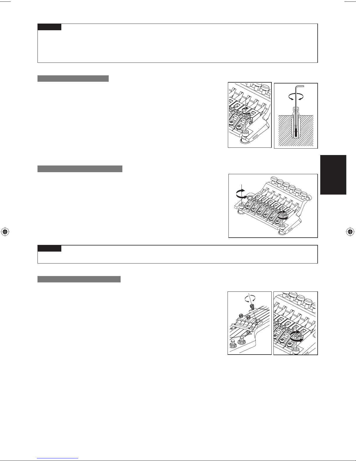
Hinweis
Lösen Sie die Saiten ausreichend, bevor Sie Tremolofedern einsetzen oder herausnehmen. Bedenken •
Sie, dass durch Entfernen aller Federn die Tremoloeinheit nicht mehr mit der Gitarre verbunden ist.
Um das Tremolo wieder zu montieren, platzieren Sie die Messerkante des Tremolos sicher in der Kerbe •
der Stehbolzen und setzen Sie dann die Tremolofedern ein.
STEHBOLZENSICHERUNG
Der Edge/Lo-Pro-Edge-Tremolosteg verwendet einen Sicherungsmechanismus
für die Stehbolzen.
1 Führen Sie einen Inbusschlüssel (1,5 mm) durch die obere Öffnung des
Stehbolzens.
2 Drehen Sie die Stehbolzen-Sicherungsschraube im Uhrzeigersinn, bis sie
fest an der Ankermutter sitzt und sich nicht weiter drehen lässt.
Die Stehbolzensicherung löst sich, wenn Sie die Stehbolzen-Sicherungss- ※
chraube lösen.
EINSTELLEN DER SAITENLAGE
Verwenden Sie zum Einstellen der Höhe der gesamten Tremoloeinheit einen
Inbusschlüssel (4mm), um die Stehbolzen links und rechts der Tremoloeinheit
zu verstellen. (Es ist nicht möglich, die Höhe einzelner Saiten einzustellen.)
DEUTSCH
Hinweis
Achten Sie darauf, dass die Stehbolzensicherung gelöst ist, bevor Sie die Saitenlage einstellen.•
EINSTELLEN DER INTONATION
Verwenden Sie einen Inbusschlüssel (3 mm) zum Lösen der Schrauben der
1
Druckplättchen, und entspannen Sie die Saiten ausreichend.
2
Verwenden Sie einen Inbusschlüssel (2 mm) zum Lösen der Sattelsicherungsschrauben, und stellen Sie die Sattelposition ein.
Bevor Sie die Intonation prüfen, ziehen Sie die Sattelsicherungsschrau- ※
ben fest und stimmen Sie die Gitarre genau. Wenn Sie die Einstellungen
abgeschlossen haben, ziehen Sie die Sattelsicherungsschrauben und die
Schrauben der Klemmplättchen fest.
77
Page 80

WECHSELN DER SAITEN
Verwenden Sie einen Inbusschlüssel (3 mm) zum Lösen der Schrauben der
1
Druckplättchen, und ziehen Sie die Saite aus dem Stimmwirbel heraus.
2
Verwenden Sie einen Inbusschlüssel (3 mm) zum Lösen der Saitenstopperschrauben der Tremoloeinheit, ziehen Sie die Saite aus dem Sattel heraus und
entfernen Sie sie.
3
Schneiden Sie mit einem Seitenschneider das Kugelende der neuen Saite ab.
4
Führen Sie das Ende der Saite, von dem Sie die Kugel abgeschnitten haben,
zwischen Sattel und dem Block des Saitenhalters ein, und drehen Sie die
Saitenstopperschraube fest, um die Saite zu befestigen.
5
Wickeln Sie die Saite um den Stimmwirbel, und stimmen Sie sie.
6 Wenn Sie fertig gestimmt haben, ziehen Sie die Schrauben der
Druckplättchen fest
.
EDGE
Lo-Pro EDGE
Wenn Sie alle Saiten zugleich entfernen, ändert sich der Winkel der Trem- ※
oloeinheit beträchtlich, weshalb wir empfehlen, die Saiten einzeln und
nacheinander zu wechseln. Wenn Sie trotzdem alle Saiten gleichzeitig
entfernen möchten, wird das Stimmen einfacher, wenn Sie ein Stoffstück
unter die Tremoloeinheit schieben, sodass sich der Winkel der Tremoloeinheit nicht stark ändert.
Hinweis
Stellen Sie vor dem Stimmen sicher, dass die Saitenstopperschrauben richtig festgezogen wurden.•
FEINSTIMMUNG
Auch wenn Sie die Schrauben der Klemmplättchen festgezogen haben,
können Sie die einzelnen Saiten mit den Feinstimmschrauben stimmen.
Der Einstellbereich dieser Schrauben nach dem Festziehen der
Klemmplättchenschrauben ist am größten, wenn Sie vor dem Stimmen
darauf achten, dass die Feinstimmschrauben etwa in der Mitte des
Einstellwegs sind.
EDGE
Lo-Pro EDGE
78
Page 81

EDGE-III-TREMOLOSTEG
Überblick■ Rückseite■
1
3
2
1
6
1
Messerkante
2
Sattelklemmschraube
3
Saitenklemmblock
4
Tremoloarm Buchse
MONTAGE DES TREMOLOHEBELS
1 Der Tremolohebel besitzt eine Ein-/Ausrastfunktion. Halten Sie den Tremolohebel in
der Beuge fest, und drücken Sie ihn fest in die entsprechende Aufnahme in der
Grundplatte.
54
5
Saitenklemmschraube
6
Feinstimmschraube
7
Tremolofeder
8
Federbefestigunsschraube
7
※ Der Tremolohebel des EDGE III Herman Li Ver., montiert an einer EGEN8,
ist eine schraubbare Ausführung. Drehen Sie nach dem Einsetzen in die
Aufnahme am Tremolohebel, um ihn zu befestigen.
2 Verwenden Sie zum Einstellen der Festigkeit des Tremolohebels einen Inbusschlüs-
sel (2 mm) zur Justierung der Biegemoment-Einstellschraube in der Einstellöffnung
seitlich am Tremoloblock. Durch Anziehen der Biegemoment-Einstellschraube wird der
Tremolohebel fester; durch Lösen der Schraube wird der Arm lockerer.
3 Zum Einstellen der Höhe des Tremolohebels entfernen Sie die Abdeckung der Trem-
olofeder hinten an der Gitarre und verwenden Sie einen Inbusschlüssel (3 mm) zum
Drehen der Höhen-Einstellschrauben an der Unterseite des Tremoloblocks. Eindrehen
der Schrauben im Uhrzeigersinn vergrößert die Höhe.
8
DEUTSCH
Hinweis
Zusätzlich zur beschriebenen Biegemoment-Einstellschraube besitzt der Tremolohebel eine weitere an •
der Unterseite des Tremoloblocks.
Die Biegemoment-Einstellschraube an der Unterseite des Tremoloblocks wurde bereits ab Werk einges-
tellt; falls sie eingestellt werden muss, demontieren Sie die Tremoloeinheit von der Gitarre und stellen
Sie dann die Schraube ein.
Bevor Sie den T remolohebel montieren, stellen Sie sicher, dass die Biegemoment-Einstellschraube sich nicht •
gelöst hat oder herausgefallen ist.
79
Page 82

EINSTELLEN DES WINKELS DER TREMOLOEINHEIT
Der Winkel der Tremoloeinheit wird eingestellt, indem das Verhältnis
zwischen der Saitenspannung und der Spannung der Tremolofedern an
der Korpusrückseite verändert wird.
Sie erhalten die optimale Spielfähigkeit, indem Sie dieses Verhältnis so
einstellen, dass das Tremolo in etwa parallel zur Korpusoberfl äche liegt.
1 Prüfen Sie den Winkel des Tremolos bei genau gestimmter Gitarre.
Wenn das Tremolo nach vorne geneigt ist, führen Sie einen Kreuzschlitz-
2
schraubendreher durch den Spalt in der Abdeckung der Tremolofedern an
der Korpusrückseite ein, und ziehen Sie die Schraube an, um die Spannung
der Tremolofedern zu erhöhen.
3
Ist das Tremolo nach hinten geneigt, lösen Sie die Schraube, um die Spannung der Tremolofedern zu verringern.
Der Winkel der Tremoloeinheit beeinfl usst auch die Stimmung, da sich das Verhältnis zwischen Saiten- und Fed- ※
erspannung bei jeder Einstellung der Tremolofedern ändert. Während dieser Einstellung müssen Sie die Gitarre
fortwährend nachstimmen.
TREMOLOFEDERN
Bei Auslieferung der Gitarre wurde sie mit drei parallel installierten Tremolofedern eingestellt.
Wenn das Spannungsverhältnis zwischen Saiten und Tremolofedern sich deutlich verändert hat, z.
B. weil Sie Saiten anderer Stärke verwenden oder die Gitarre tiefer gestimmt haben, können Sie die Anzahl
der Tremolofedern oder die Stellung der Federn verändern.
1 Verwenden Sie einen Kreuzschlitzschraubendreher, um die
Sicherungsleiste zu lösen.
2 Wenn Sie die Spannung erhöhen möchten, installieren Sie die äußeren
beiden T remolof edern diagonal.
3 Wenn Sie die Spannung verringern möchten, entfernen Sie die mittlere
Tremolofeder.
Wenn Sie vier oder mehr Tremolofedern einsetzen möchten,
befestigen Sie diese mittels der Schraubenlöcher, die zur Befestigung
der Sicherungsleiste dienten. (Es ist dann nicht mehr möglich, die
Sicherungsleiste zu montieren.)
Hinweis
Lösen Sie die Saiten ausreichend, bevor Sie Tremolofedern einsetzen oder herausnehmen. Bedenken •
Sie, dass durch Entfernen aller Federn die Tremoloeinheit nicht mehr mit der Gitarre verbunden ist.
Um das Tremolo wieder zu montieren, platzieren Sie die Messerkante des Tremolos sicher in der Kerbe •
der Stehbolzen und setzen Sie dann die Tremolofedern ein.
EINSTELLEN DER SAITENLAGE
Verwenden Sie zum Einstellen der Höhe der gesamten Tremoloeinheit
einen Inbusschlüssel (3 mm), um die Stehbolzen links und rechts der
Tremoloeinheit zu verstellen. (Es ist nicht möglich, die Höhe einzelner
Saiten einzustellen.)
80
Page 83

EINSTELLEN DER INTONATION
1 Verwenden Sie einen Inbusschlüssel (3 mm) zum Lösen der Schrauben der
Druckplättchen, und entspannen Sie die Saiten ausreichend.
2 Verwenden Sie einen Inbusschlüssel (2 mm) zum Lösen der Sattelsich-
erungsschrauben, und stellen Sie die Sattelposition ein.
Bevor Sie die Intonation prüfen, ziehen Sie die Sattelsicherungsschrauben fest und stimmen Sie die Gitarre genau. ※
Wenn Sie die Einstellungen abgeschlossen haben, ziehen Sie die Sattelsicherungsschrauben und die Schrauben
der Klemmplättchen fest.
WECHSELN DER SAITEN
DEUTSCH
1 Verwenden Sie einen Inbusschlüssel (3 mm) zum Lösen der Schrauben
der Druckplättchen, und ziehen Sie die Saite aus dem Stimmwirbel heraus.
2 Verwenden Sie einen Inbusschlüssel (3 mm) zum Lösen der Saitenstopper-
schrauben der Tremoloeinheit, ziehen Sie die Saite aus dem Sattel heraus
und entfernen Sie sie.
Schneiden Sie mit einem Seitenschneider das Kugelende der neuen Saite ab.
3
4 Führen Sie das Ende der Saite, von dem Sie die Kugel abgeschnitten haben,
zwischen Sattel und dem Block des Saitenhalters ein, und drehen Sie die
Saitenstopperschraube fest, um die Saite zu befestigen.
5 Wickeln Sie die Saite um den Stimmwirbel, und stimmen Sie sie.
6
Wenn Sie fertig gestimmt haben, ziehen Sie die Schrauben der Druckplättchen fest.
Wenn Sie alle Saiten zugleich entfernen, ändert sich der Winkel der Tremoloeinheit beträchtlich, weshalb wir emp- ※
fehlen, die Saiten einzeln und nacheinander zu wechseln. Wenn Sie trotzdem alle Saiten gleichzeitig entfernen
möchten, wird das Stimmen einfacher, wenn Sie ein Stoffstück unter die Tremoloeinheit schieben, sodass sich der
Winkel der Tremoloeinheit nicht stark ändert.
Hinweis
Stellen Sie vor dem Stimmen sicher , dass die Saitenstopperschr auben richtig f estgez ogen wurden.•
FEINSTIMMUNG
Auch wenn Sie die Schrauben der Klemmplättchen festgezogen haben,
können Sie die einzelnen Saiten mit den Feinstimmschrauben stimmen.
Der Einstellbereich dieser Schrauben nach dem Festziehen der
Klemmplättchenschrauben ist am größten, wenn Sie vor dem Stimmen darauf
achten, dass die Feinstimmschrauben etwa in der Mitte des Einstellwegs sind.
81
Page 84

EDGE-ZERO2-TREMOLOSTEG
Überblick■
1
3
2
1
1 Messerkante
2 Sattelklemmschraube
3 Saitenklemmblock
4 T remoloarm Buchse
5 Saitenklemmschraube
6 Feinstimmschraube
7 T remolzugf eder
8 Null-Punkt-Federn
9 Stopper
: Null-Punkt-Stange
A T remolob lock
B Federeinstellknopf
C T remolof eder
6
5
4
D Federbefestigunsschraube
Rückseite■ 1 Rückseite■ 2
B
7
7
8
A
8
9
:
C
D
MONTAGE DES TREMOLOHEBELS
1 Der Tremolohebel besitzt eine einteilige Ein-/Ausrastfunktion mit einer
Kappe zum Einstellen des Biegemoments. Stecken Sie den Tremolohebel
in die entsprechende Buchse an der Grundplatte.
2 Drehen Sie an der Biegemoment-Einstellkappe, um den Tremolohebel
zu befestigen. Der Tremolohebel wird umso fester, je stärker Sie die
Biegemoment-Einstellkappe anziehen.
EINSTELLEN DES WINKELS DER TREMOLOEINHEIT / EINSTELLEN DES ZERO-POINT-SYSTEMS
・ Modelle ohne Zero-Point-System
Der Winkel der Tremoloeinheit wird eingestellt, indem das Verhältnis zwischen der Saitenspannung und der
Spannung der Tremolofedern an der Korpusrückseite verändert wird.
Sie erhalten die optimale Spielfähigkeit, indem Sie den Tremolohebel so einstellen, dass das Tremolo in etwa
parallel zur Korpusoberfl äche liegt.
82
Page 85

1 Prüfen Sie den Winkel des Tremolos bei genau gestimmter Gitarre.
2 Wenn das Tremolo nach vorne geneigt ist, führen Sie einen Kreuzschlitz-
schraubendreher durch den Spalt in der Abdeckung der Tremolofedern
an der Korpusrückseite ein, und ziehen Sie die Schrauben an, um die
Spannung der Tremolofedern zu erhöhen.
3 Ist das Tremolo nach hinten geneigt, lösen Sie die Schrauben, um die
Spannung der Tremolofedern zu verringern.
Da sich das Verhältnis zwischen Saiten- und Federspannung bei jeder ※
Einstellung der Spannung der Tremolofedern ändert, beeinfl usst der Winkel der Tremoloeinheit auch die Stimmung. Während dieser Einstellung
müssen Sie die Gitarre fortwährend nachstimmen.
・Modelle mit Zero-Point-System
Der Winkel der Tremoloeinheit wird eingestellt, indem das
Verhältnis zwischen der Saitenspannung und der Spannung des
Nullpunktsystems an der Korpusrückseite verändert wird. Der EdgeZero-2-Tremolosteg ist so beschaffen, dass das Tremolo in etwa parallel
mit der Oberfl äche der Korpusdecke liegt, wenn das Nullpunktsystem
richtig eingestellt ist, und es erbringt in diesem Zustand optimale
Leistung. Wenn das Nullpunktsystem richtig eingestellt ist, hat die
Stoppstange festen Kontakt mit dem Tremoloblock und die Stoppstange
berührt den Stopper.
DEUTSCH
1 Prüfen Sie das Nullpunktsystem bei genau gestimmter Gitarre.
Wenn die Stoppstange den Stopper nicht berührt (d. h. wenn der Tremolo-
2
block die Stoppstange anhebt), drehen Sie an der Federeinstellschraube
an der Korpusrückseite in Richtung „Plus“, um die Hauptfeder zu spannen
3 Wenn der Tremoloblock keinen Kontakt mit der Stoppstange hat (d. h.
wenn das Tremolo nach hinten geneigt ist), drehen Sie an der Federeinstellschraube an der Korpusrückseite in Richtung „Minus“, um die
Hauptfeder zu entspannen.
TREMOLOFEDER / NULLPUNKTSYSTEM
・Modelle ohne Zero-Point-System
.
Bei Auslieferung wurde die Gitarre mit drei parallel installierten
Tremolofedern ausgestattet.
Wenn das Spannungsverhältnis zwischen Saiten und Tremolofedern
sich deutlich verändert hat, z. B. weil Sie Saiten anderer Stärke
verwenden oder die Gitarre tiefer gestimmt haben, können Sie die
Anzahl der Tremolofedern oder die Stellung der Federn verändern.
1 Verwenden Sie einen Kreuzschlitzschraubendreher, um die
Sicherungsleiste zu lösen.
2 Wenn Sie die Spannung erhöhen möchten, installieren Sie die äußeren
beiden T remolof edern diagonal.
3 Wenn Sie die Spannung verringern möchten, entfernen Sie die mittlere
Tremolofeder.
Wenn Sie vier oder mehr Tremolofedern einsetzen möchten, befestigen Sie
diese mittels der Schraubenlöcher, die zur Befestigung der Sicherungsleiste
dienten. (Es ist dann nicht mehr möglich, die Sicherungsleiste zu montieren.)
83
Page 86

Hinweis
Lösen Sie die Saiten ausreichend, bevor Sie Tremolofedern einsetzen oder herausnehmen.•
Bedenken Sie, dass durch Entfernen aller Federn die Tremoloeinheit nicht mehr mit der Gitarre verbunden ist.
Um das Tremolo wieder zu montieren, platzieren Sie die Messerkante des Tremolos sicher in der Kerbe der •
Stehbolzen und setzen Sie dann die Tremolofedern ein.
・Modelle mit Zero-Point-System
Wenn Sie das Nullpunktsystem deaktivieren, können Sie es als
herkömmliches schwebendes Tremolo verwenden.
Wenn das Nullpunktsystem deaktiviert ist, wird der Winkel, in dem das
Tremolo befestigt ist, durch die Balance zwischen der Saitenspannung
und der Spannung der Hauptfedern des Tremoloblocks bestimmt.
Für optimale Spielfähigkeit stellen Sie das Tremolo so ein, dass es in etwa
parallel zur Korpusdecke liegt.
1 Entfernen Sie die Stoppstange und die Nebenfeder, während Sie den Hebel
in Aufwärtsstellung halten (d. h. so, dass der Tremoloblock von der Stoppstange entfernt ist).
2 Prüfen Sie den Winkel des Tremolos bei genau gestimmter Gitarre.
3 Ist das Tremolo nach vorne geneigt, drehen Sie die Federeinstellschraube in
Richtung „Plus“, um die Spannung der Hauptfeder zu erhöhen.
4 Ist das Tremolo nach hinten geneigt, drehen Sie die Federein-
stellschraube in Richtung „Minus“, um die Spannung der Hauptfeder zu
verringern.
Bei deaktiviertem Nullpunktsystem beeinfl usst der Winkel der Tremoloeinheit ※
auch die Stimmung, da sich das Verhältnis zwischen Saiten- und Federspannung bei jeder Einstellung der Spannung der Tremolofedern ändert.
Während dieser Einstellung müssen Sie die Gitarre fortwährend nachstimmen
.
STEHBOLZENSICHERUNG
Der Edge/Zero2-Tremolosteg verwendet einen Sicherungsmechanismus
für die Stehbolzen.
1
Führen Sie einen Inbusschlüssel (2 mm) durch die obere Öffnung des
Stehbolzens.
2 Drehen Sie die Stehbolzen-Sicherungsschraube im Uhrzeigersinn,
bis sie fest an der Ankermutter sitzt und sich nicht weiter drehen lässt.
The stud lock will be released when you loosen the stud lock bolt. ※
EINSTELLEN DER SAITENLAGE
Verwenden Sie zum Einstellen der Höhe der gesamten Tremoloeinheit
einen Inbusschlüssel (3 mm), um die Stehbolzen links und rechts der
Tremoloeinheit zu verstellen. (Es ist nicht möglich, die Höhe einz elner
Saiten einzustellen.)
Hinweis
Stellen Sie vor dem Stimmen sicher, dass die Saitenstopperschrauben richtig festgezogen wurden.•
EINSTELLEN DER INTONATION
1 Verwenden Sie einen Inbusschlüssel (3 mm)
zum Lösen der Schraubender Druckplättchen, und entspannen Sie die Saiten
ausreichend.
2
Verwenden Sie einen Inbusschlüssel (2 mm)
zum Lösen der Sattelsicherungsschrauben,
und stellen Sie die Sattelposition ein.
84
Page 87

Bevor Sie die Intonation prüfen, ziehen Sie die Sattelsicherungsschrauben fest und stimmen Sie die Gitarre genau. ※
Wenn Sie die Einstellungen abgeschlossen haben, ziehen Sie die Sattelsicherungsschrauben und die Schrauben
der Klemmplättchen fest.
WECHSELN DER SAITEN
1 Verwenden Sie einen Inbusschlüssel (3 mm) zum Lösen der Schrauben der Druckplättchen, und ziehen Sie die
Saite aus dem Stimmwirbel heraus.
2 Verwenden Sie einen Inbusschlüssel (3 mm) zum Lösen der Saitenstopperschrauben der Tremoloeinheit, ziehen
Sie die Saite aus dem Sattel heraus und entfernen Sie sie.
3 Schneiden Sie mit einem Seitenschneider das Kugelende der neuen Saite ab.
4 Führen Sie das Ende der Saite, von dem Sie die Kugel abgeschnitten haben,
zwischen Sattel und dem Block des Saitenhalters ein, und drehen Sie die
Saitenstopperschraube fest, um die Saite zu befestigen.
5 Wickeln Sie die Saite um den Stimmwirbel, und stimmen Sie sie.
Wenn Sie fertig gestimmt haben, ziehen Sie die Schrauben der Druckplättchen fest.
6
DEUTSCH
Wenn Sie bei Tremolostegen, die nicht mit dem Nullpunktsystem aus- ※
gestattet sind, alle Saiten zugleich entfernen, ändert sich der Winkel der
Tremoloeinheit beträchtlich, weshalb wir empfehlen, die Saiten einzeln und
nacheinander zu wechseln. Wenn Sie trotzdem alle Saiten gleichzeitig entfernen möchten, wird das Stimmen einfacher, wenn Sie ein Stoffstück unter
die Tremoloeinheit schieben, sodass sich der Winkel der Tremoloeinheit nicht
stark ändert.
Hinweis
Stellen Sie vor dem Stimmen sicher , dass die Saitenstopperschr auben richtig f estgez ogen wurden.•
FEINSTIMMUNG
Auch wenn Sie die Schrauben der Klemmplättchen festgezogen haben,
können Sie die einzelnen Saiten mit den Feinstimmschrauben stimmen.
Der Einstellbereich dieser Schrauben nach dem Festziehen der
Klemmplättchenschrauben ist am größten, wenn Sie vor dem Stimmen
darauf achten, dass die Feinstimmschrauben etwa in der Mitte des
Einstellwegs sind.
85
Page 88

ZR-TREMOLOSTEG
Überblick■ Rückseite■
6
1
5
2
1 Sattelklemmschraube
2 Saitenklemmblock
3 T remoloarm Buchse
4 Saitenklemmschraube
5 Feinstimmschraube
6 Mensureinstellschraube
MONTAGE DES TREMOLOHEBELS
3
B
7
7
8
A
4
8
9
:
7 T remolzugf eder
8 Null-Punkt-Federn
9 Stopper
: Null-Punkt-Stange
A T remolob lock
B Federeinstellknopf
1 Der Tremolohebel besitzt eine einteilige Ein-/Ausrastfunktion mit einer
Kappe zum Einstellen des Biegemoments. Stecken Sie den Tremolohebel
in die entsprechende Buchse an der Grundplatte.
2 Drehen Sie an der Biegemoment-Einstellkappe, um den Tremolohebel
zu befestigen. Der Tremolohebel wird umso fester, je stärker Sie die
Biegemoment-Einstellkappe anziehen.
86
Page 89

EINSTELLEN DES WINKELS DER TREMOLOEINHEIT / EINSTELLEN DES ZERO-POINT-SYSTEMS
Der Winkel der Tremoloeinheit wird eingestellt, indem das Verhältnis
zwischen der Saitenspannung und der Spannung des Nullpunktsystems
(Zero Point) an der Korpusrückseite verändert wird. Der ZR-Tremolosteg ist
so beschaffen, dass das Tremolo in etwa parallel mit der Oberfl äche der
Korpusdecke liegt, wenn das Nullpunktsystem richtig eingestellt ist, und es
erbringt in diesem Zustand optimale Leistung. Wenn das Nullpunktsystem
richtig eingestellt ist, hat die Stoppstange festen Kontakt mit dem
Tremoloblock und die Stoppstange berührt den Stopper.
1 Prüfen Sie das Nullpunktsystem bei genau gestimmter Gitarre.
Wenn die Stoppstange den Stopper nicht berührt (d. h. wenn der Tremolo-
2
block die Stoppstange anhebt), drehen Sie an der Federeinstellschraube
an der Korpusrückseite in Richtung „Plus“, um die Hauptfeder zu spannen
.
3 Wenn der Tremoloblock keinen Kontakt mit der Stoppstange hat (d. h.
wenn das Tremolo nach hinten geneigt ist), drehen Sie an der Federeinstellschraube an der Korpusrückseite in Richtung „Minus“, um die
Hauptfeder zu entspannen.
DEAKTIVIEREN DES NULLPUNKTSYSTEMS (VERWENDUNG ALS HERKÖMMLICHES SCHWEBENDES TREMOLO)
Wenn Sie das Nullpunktsystem deaktivieren, können Sie es auch als herkömmliches schwebendes Tremolo
verwenden.
Wenn das Nullpunktsystem deaktiviert ist, wird der Winkel, in dem das Tremolo befestigt ist, durch die Balance
zwischen der Saitenspannung und der Spannung der Hauptfedern des Tremoloblocks bestimmt.
Für optimale Spielfähigkeit stellen Sie das Tremolo so ein, dass es in etwa parallel zur Korpusdecke liegt.
1 Entfernen Sie die Stoppstange und die Nebenfeder, während Sie den
Hebel in Aufwärtsstellung halten (d. h. so, dass der Tremoloblock von der
Stoppstange entfernt ist).
2 Prüfen Sie den Winkel des Tremolos bei genau gestimmter Gitarre.
DEUTSCH
3 Ist das Tremolo nach vorne geneigt, drehen Sie die Federeinstellschraube
in Richtung „Plus“, um die Spannung der Hauptfeder zu erhöhen.
4 Ist das Tremolo nach hinten geneigt, drehen Sie die Federeinstellschraube
in Richtung „Minus“, um die Spannung der Hauptfeder zu verringern.
※ Bei deaktiviertem Nullpunktsystem beeinfl usst der Winkel der Tremoloeinheit auch die Stimmung, da sich
das Verhältnis zwischen Saiten- und Federspannung bei jeder Einstellung der Spannung der Tremolofedern ändert. Während dieser Einstellung müssen Sie die Gitarre fortwährend nachstimmen.
87
Page 90

EINSTELLEN DER SAITENLAGE
Verwenden Sie zum Einstellen der Höhe der gesamten Tremoloeinheit
einen Inbusschlüssel (3 mm), um die Stehbolzen links und rechts der
Tremoloeinheit zu verstellen. (Es ist nicht möglich, die Höhe einzelner
Saiten einzustellen.)
EINSTELLEN DER INTONATION
1 Entfernen Sie die Intonationseinstellschrauben aus der Tremoloeinheit,
und drehen Sie diese in die Gewinde an der Tremolorückseite ein, bis die
Spitze der einzelnen Schrauben die Kante der Tremoloeinheit berühren.
2 Verwenden Sie einen Inbusschlüssel (2 mm) zum Lösen der Sattelsich-
erungsschraube, und stellen Sie die Sattelstellung mit der Intonationseinstellschraube ein.
Bevor Sie die Intonation prüfen, ziehen Sie die Sattelsicherungsschrauben ※
fest und stimmen Sie die Gitarre genau. Verwenden Sie einen Inbusschlüssel (3 mm) zum Lösen der Schrauben der Druckplättchen. Wenn Sie die
Einstellungen abgeschlossen haben, ziehen Sie die Sattelsicherungsschrauben und die Schrauben der Klemmplättchen fest, und drehen Sie die
Intonationseinstellschrauben wieder in die Tremoloeinheit ein.
WECHSELN DER SAITEN
1
Verwenden Sie einen Inbusschlüssel (3 mm) zum Lösen der Schrauben
der Druckplättchen, und ziehen Sie die Saite aus dem Stimmwirbel heraus.
2 Verwenden Sie einen Inbusschlüssel (3 mm) zum Lösen der Saitenstop-
perschrauben der Tremoloeinheit, ziehen Sie die Saite aus dem Sattel
heraus und entfernen Sie sie.
3
Schneiden Sie mit einem Seitenschneider das Kugelende der neuen Saite ab.
4 Führen Sie das Ende der Saite, von dem Sie die Kugel abgeschnitten
haben, zwischen Sattel und dem Block des Saitenhalters ein, und drehen
Sie die Saitenstopperschraube fest, um die Saite zu befestigen.
5 Wickeln Sie die Saite um den Stimmwirbel, und stimmen Sie sie.
Wenn Sie fertig gestimmt haben, ziehen Sie die Schrauben der Druckplät-
6
tchen fest.
Hinweis
Stellen Sie vor dem Stimmen sicher , dass die Saitenstopper-•
schrauben richtig festgezogen wurden.
FEINSTIMMUNG
Auch wenn Sie die Schrauben der Klemmplättchen festgezogen haben,
können Sie die einzelnen Saiten mit den Feinstimmschrauben stimmen.
Der Einstellbereich dieser Schrauben nach dem Festziehen der
Klemmplättchenschrauben ist am größten, wenn Sie vor dem Stimmen
darauf achten, dass die Feinstimmschrauben etwa in der Mitte des
Einstellwegs sind.
88
Page 91

STD-DL-TREMOLOSTEG
Gesamtansicht■ Ansicht von hinten■
56
4
7
1
1 Messerkante
2 Sattelklemmschraube
3 Saitenklemmblock
4 Tremoloarm Buchse
MONTAGE DES TREMOLOHEBELS
1 Der Tremolohebel besitzt eine einteilige Ein-/Ausrastfunktion mit einer Kappe zum Einstellen des Biegemoments.
Stecken Sie den Tremolohebel in die entsprechende Buchse an der Grundplatte.
2 Drehen Sie an der Biegemoment-Einstellkappe, um den Tremolohebel zu befestigen.
Der Tremolohebel wird umso fester, je stärker Sie die Biegemoment-Einstellkappe anziehen.
EINSTELLEN DES WINKELS DER TREMOLOEINHEIT
123
5 Saitenklemmschraube
6 Feinstimmschraube
7 Tremolofeder
8 Federbefestigunsschr aube
8
Der Winkel der Tremoloeinheit wird eingestellt, indem das Verhältnis
zwischen der Saitenspannung und der Spannung der Tremolofedern an
der Korpusrückseite verändert wird.
Sie erhalten die optimale Spielfähigkeit, indem Sie dieses Verhältnis so
einstellen, dass das Tremolo in etwa parallel zur Korpusoberfl äche liegt.
DEUTSCH
1 Prüfen Sie den Winkel des Tremolos bei genau gestimmter Gitarre.
2 Wenn das Tremolo nach vorne geneigt ist, führen Sie einen Kreuzschlitz-
schraubendreher durch den Spalt in der Abdeckung der Tremolofedern an
der Korpusrückseite ein, und ziehen Sie die Schraube an, um die Spannung der Tremolofedern zu erhöhen.
Ist das Tremolo nach hinten geneigt, lösen Sie die Schraube, um die Span-
3
nung der Tremolofedern zu verringern.
Der Winkel der Tremoloeinheit beeinfl usst auch die Stimmung, da sich das Verhältnis zwischen Saiten- und Fed- ※
erspannung bei jeder Einstellung der Tremolofedern ändert. Während dieser Einstellung müssen Sie die Gitarre
fortwährend nachstimmen.
89
Page 92

TREMOLOFEDERN
Bei Auslieferung der Gitarre wurde sie mit drei parallel installierten
Tremolofedern eingestellt.
Wenn das Spannungsverhältnis zwischen Saiten und Tremolofedern sich
deutlich verändert hat, z. B. weil Sie Saiten anderer Stärke verwenden
oder die Gitarre tiefer gestimmt haben, können Sie die Anzahl der
Tremolofedern oder die Stellung der Federn verändern.
1 Wenn Sie die Spannung erhöhen möchten, installieren Sie die äußeren
beiden T remolof edern diagonal.
2 Wenn Sie die Spannung verringern möchten, entfernen Sie die mittlere
Tremolofeder.
Hinweis
Lösen Sie die Saiten ausreichend, bevor Sie Tremolofedern einsetzen oder herausnehmen.•
Bedenken Sie, dass durch Entfernen aller Federn die Tremoloeinheit nicht mehr mit der Gitarre verbunden ist.
Um das Tremolo wieder zu montieren, platzieren Sie die Messerkante des Tremolos sicher in der Kerbe der •
Stehbolzen und setzen Sie dann die Tremolofedern ein.
EINSTELLEN DER SAITENLAGE
Verwenden Sie zum Einstellen der Höhe der gesamten Tremoloeinheit einen Inbusschlüssel
(3mm), um die Stehbolzen links und rechts der Tremoloeinheit zu verstellen. (Es ist nicht
möglich, die Höhe einzelner Saiten einzustellen.)
EINSTELLEN DER INTONATION
1 Verwenden Sie einen Inbusschlüssel (3 mm) zum Lösen der Schrauben der
Druckplättchen, und entspannen Sie die Saiten ausreichend.
2 Verwenden Sie einen Inbusschlüssel (2 mm) zum Lösen der Sattelsich-
erungsschrauben, und stellen Sie die Sattelposition ein.
Bevor Sie die Intonation prüfen, ziehen Sie die Sattelsicherungsschrau- ※
ben fest und stimmen Sie die Gitarre genau. Wenn Sie die Einstellungen
abgeschlossen haben, ziehen Sie die Sattelsicherungsschrauben und die
Schrauben der Klemmplättchen fest.
WECHSELN DER SAITEN
Verwenden Sie einen Inbusschlüssel (3 mm) zum Lösen der Schrauben
1
der Druckplättchen, und ziehen Sie die Saite aus dem Stimmwirbel heraus
2 Verwenden Sie einen Inbusschlüssel (3 mm) zum Lösen der Saitenstop-
perschrauben der Tremoloeinheit, ziehen Sie die Saite aus dem Sattel
heraus und entfernen Sie sie.
3
Schneiden Sie mit einem Seitenschneider das Kugelende der neuen Saite ab.
4 Führen Sie das Ende der Saite, von dem Sie die Kugel abgeschnitten
haben, zwischen dem Sattel und dem Block des Saitenhalters ein, und
drehen Sie die Saitenstopperschraube fest, um die Saite zu befestigen.
5 Wickeln Sie die Saite um den Stimmwirbel, und stimmen Sie sie.
6
Wenn Sie fertig gestimmt haben, ziehen Sie die Schrauben der Druckplättchen fest.
Wenn Sie alle Saiten zugleich entfernen, ändert sich der Winkel der Tremoloe- ※
inheit beträchtlich, weshalb wir empfehlen, die Saiten einzeln und nacheinander
zu wechseln. Wenn Sie trotzdem alle Saiten gleichzeitig entfernen möchten,
wird das Stimmen einfacher, wenn Sie ein Stoffstück unter die Tremoloeinheit
schieben, sodass sich der Winkel der Tremoloeinheit nicht stark ändert.
Hinweis
.
Stellen Sie vor dem Stimmen sicher , dass die Saitenstopperschr auben richtig f estgez ogen wurden.•
FEINSTIMMUNG
Auch wenn Sie die Schrauben der Klemmplättchen festgezogen haben, können Sie die
einzelnen Saiten mit den Feinstimmschrauben stimmen. Der Einstellbereich dieser
Schrauben nach dem Festziehen der Klemmplättchenschrauben ist am größten, w enn Sie
vor dem Stimmen darauf achten, dass die Feinstimmschr auben etwa in der Mitte des
Einstellwegs sind.
90
Page 93
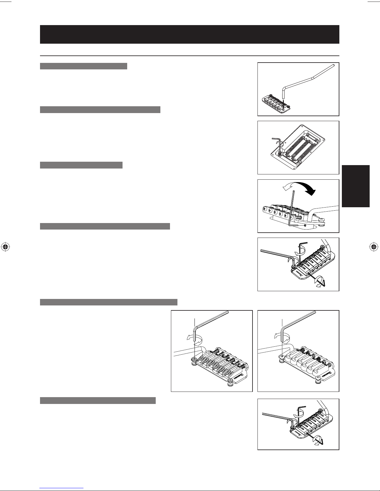
Non Locking Tremolo
F A T/SA T/STD TREMOLO
TREMOLOARM-INSTALLATION
Der Tremoloarm kann leicht eingesetzt und entfernt werden. Setzen Sie den
Arm in die Armöffnung an der Tremolo-Basisplatte. Ziehen Sie den Arm zum
Entfernen hoch.
TREMOLOARM-EINSTELLUNG (SAT PRO2)
Zum Einstellen der Höhe des Arms entfernen Sie die TremoloFederabdeckung von der Rückseite der Gitarre und verwenden einen 3
mm großen Inbusschlüssel zum drehen der Höheneinstellschraube an der
Unterseite des Tremoloblocks. Durch dieses Festziehen im Uhrzeigersinn
wird die Höhe angehoben.
ARMDREHUNG-DREHKRAFT
Die Drehkraft des Arms kann eingestellt werden, indem der Tremolo
angehoben wird und ein 1,5 mm großer Inbusschlüssel in die Schraube (A)
am Tremoloblock eingesetzt wird.
Durch Drehen dieser Schraube im Uhrzeigersinn wird die Arm-Drehkraft
gesteigert, und durch Drehen der Schraube gegen den Uhrzeigersinn wird
die Arm-Drehkraft verringert.
EINSTELLUNG DER SAITENHÖHE (SAT PRO2)
Zum Einstellen der Saitenlage jeder Saite verwenden Sie einen 1,5 mm großen
Inbusschlüssel zum Drehen der Schraube auf dem Sattel (C). Die Gesamthöhe kann
auf jeder Seite der SAT PRO2 Tremoloeinheit eingestellt werden. Zum Einstellen der
Höhe verwenden Sie einen 3 mm großen Inbusschlüssel zum Drehen des Stutzens
(D) an einer Seite des Geräts. Seien Sie beim Einstellen der Höhe der gesamten
Tremoloeinheit vorsichtig; stellen Sie beide Seiten auf die gleiche Höhe ein, um
optimale Tremolofunktion zu erzielen.
EINSTELLUNG DER SAITENHÖHE (FAT10/SAT10)
Die Höheneinstellung des Tremolo kann erhöht
oder gesenkt werden, indem die Drehzapfen
(C) eingestellt werden, auf denen das Tremolo
befestigt ist. Diese liegen an beiden Seiten
vorne am Steg. Durch Drehen im Uhrzeigersinn
wird das Tremolo gesenkt; durch Drehen
gegen den Uhrzeigersinn wird das Tremolo
angehoben.
(C)
DEUTSCH
(A)
(C)
(D)
(E)
(C)
INTONATIONSEINSTELLUNG (SAT PRO2)
Zum Einstellen der Intonation verwenden Sie einen 1,5 mm großen
Inbusschlüssel zum Drehen der Schraube an der Rückseite des Sattels (E).
Drehen Sie die Schraube im Uhrzeigersinn, um den Sattel nach hinten zu
bewegen, oder gegen den Uhrzeigersinn, um den Sattel nach vorne zu
bewegen.
FAT10
SAT10
(C)
(D)
(E)
SAT PRO2
91
Page 94

INTONATIONSEINSTELLUNG (FAT10/SAT10)
Die Intonation kann durch Einstellen
des Sattels nach vorne oder hinten mit
einem Kreuzschlitzschraubenzieher
(+) an der Intonationseinstellschraube
hinten am Steg reguliert werden.
FAT10 SAT10
EINSTELLUNG DER INTONATION U. DER SAITENHÖHE (FAT 6/STD)
Die Intonation kann durch Einstellen des Sattels nach vorne oder
hinten mit einer Kreuzschlitzschraube (+) hinten am Steg eingestellt
werden. Die Saitenhöhe wird durch Heben oder Senken der kleinen
Inbusschrauben mit einem Schraubenschlüssel an einer Seite des
Sattels geregelt.
ERSETZEN DER SAITEN
Zum Austauschen von Saiten fädeln Sie die neuen Saiten durch die
Saitenhülsen an der Rückseite der Gitarre. Die Saiten werden dann
durch den Tremoloblock gefädelt und über den Sattel geführt.
FAT/SAT (AUSGENOMMEN FAT6) EINSTELLEN DER TREMOLOFEDER
Ein Standard-Tremolo kann so eingestellt werden, dass die Tonlage
angehoben werden kann, wenn der Tremoloarm zurückgezogen wird,
um die Tremolo-Federn unter der Tremolo-Vertiefung an der Rückseite
der Gitarre zu lösen. Ein Nachteil dieses Verfahrens ist, dass sich
die Tonlage des Instruments erhöht, falls eine Saite reißt. Zur Abhilfe
justieren Sie die Tremoloplatte so, dass sie bündig auf dem Körper sitzt,
indem Sie die Tremolo-Federn festziehen. Wählen Sie die
Anzahl und Platzierung der Tremolo-Federn entsprechend
der Saitenstärke und der Tremolo-Einstellung.
SCHWEBEND PARALLEL
92
Page 95

Entretien
FRANÇAIS MANUEL DʼENTRETIEN
FIXATIONS
Multioutils Tige de vibrato
Gamme PREMIUM - Chevalet
vibrato Edge
Gamme PREMIUM - Edge-Zero
II avec ZPS
Gamme PREMIUM - Chevalet
vibrato ZR avec ZPS2
Gamme PREMIUM - Chevalet
Tight-End R
Chevalet vibrato Edge III ○ ○○○○
Edge-Zero II avec ZPS ○ ○ ○○
Edge-Zero II sans ZPS ○ ○ ○○
Chevalet vibrato FAT6 ○ ○ ○○
Chevalet vibrato FAT10 ○ ○ ○○
Chevalet FX Edge III ○○○
Chevalet FX Edge III-8 ○○○
Chevalet Gibraltar standard ○ ○ ○
Chevalet Gibraltar standard 7 ○ ○ ○
Chevalet vibrato SAT10 ○ ○ ○○
Chevalet vibrato SAT-Pro II ○ ○ ○○
Chevalet vibrato STD ○
Chevalet vibrato STD-DL ○
Chevalet Tight-End ○○
Chevalet Tight-Tune ○ ○○
Chevalet vibrato ZR avec ZPS2 ○ ○ ○○
○○
○○
○○
○
1.5mm 2mm 2.5mm 3mm 4mm
Clé Allen
FRANÇAIS
Les modèles équipés de micros DiMarzio sont livrés avec une clé Allen permettant de régler la hauteur des pièces ※
polaires.
Les guitares à sept cordes équipées dʼun Chevalet vibrato Edge-Zero II avec ZPS3Fe sont dotées de ressorts ※
robustes.
93
Page 96

IDENTIFICATION DES ÉLÉMENTS DE LA GUITARE
Guitare électrique Guitare acoustique ou semi-acoustique
MECANIQUES
DʼACCORDAGE
VIS DE VERROUILLAGE
TOUCHE
SUPPORT DE SANGLE
MICRO DE
MANCHE
MICRO
CENTRAL
MICRO DE
CHEVALET
VIBRATO
JACK DE SORTIE
TIGE DE VIBRATO
SELECTEUR
MICRO
VOLUME
TONALITE
MECANIQUES
DʼACCORDAGE
SILLET DE
MANCHE
TOUCHE
MICRO DE
MANCHE
MICRO DE
CHEVALET
CHEVALET
CORDIER
SELECTEUR
MICRO
VOLUME DE
MICRO DE
MANCHE
VOLUME DE
MICRO DE
CHEVALET
TONALITE DE
MICRO DE
CHEVALET
JACK DE SORTIE
TONALITE DE MICRO DE MANCHE
Ces illustrations représentent des modèles Ibanez courants. La guitare que vous avez achetée peut ne pas ※
correspondre à ces illustrations.
Les réglages de chevalet/vibrato diffèrent selon le type de chevalet/vibrato installé.※
Pour plus dʼinformations, reportez-vous à la section chevalet/vibrato correspondante.
Pour plus dʼinformations sur les commandes de chaque modèle, reportez-vous à la section « CONTROLS ※
(Commandes) » (p. 210).
94
Page 97

ACCORDAGE
À la sortie d’usine, les guitares Ibanez sont accordées de la façon suivante :
1ère 2e 3e 4e 5e 6e 7e
6 cordes E4 B3 G3 D3 A2 E2 7 cordes E4 B3 G3 D3 A2 E2 B1
Notez que les modèles suivants sont accordés différemment.
RGD, APEX2
1ère 2e 3e 4e 5e 6e 7e
6 cordes D4 A3 F3 C3 G2 D2 7 cordes D4 A3 F3 C3 G2 D2 A1
RG8, RGA8, S8, S8QM, RGIR28FE
1ère 2e 3e 4e 5e 6e 7e 8e
D#4 A#3 F#3 C#3 G#2 D#2 A#1 F1
MTM100
1ère 2e 3e 4e 5e 6e 7e 8e
C# G# E B F# B - -
Utilisez un accordeur ou un diapason pour accorder chaque corde ouverte aux fréquences susmentionnées.
Si le son produit est plus haut que la fréquence ci-dessus, détendez la corde pour en réduire la hauteur,
et enroulez la corde par petits incréments pour l’accorder. Cette méthode simple permet de stabiliser votre
accordage. Vous risquez de devoir régler le manche ou l’intonation si vous accordez votre guitare d’une
manière différente de celle indiquée dans ces tableaux, ou si vous utilisez des cordes différentes du calibre
standard.
Pour plus d’informations sur le réglage du manche ou de l’intonation, reportez-vous aux sections
« RÉGLAGE DU MANCHE » (p. 96) ou « INTONATION » (p. 96).
FRANÇAIS
Mémo
Notez quʼun accordage extrême ou lʼutilisation de cordes non conçues pour les guitares électriques peut •
casser des éléments ou vous blesser.
REMPLACEMENT DES CORDES
Au fur et à mesure de leur utilisation, les cordes se détériorent, provoquant ainsi des bourdonnements et des
distorsions du son. Remplacez les cordes dès quʼelles commencent à rouiller ou à se décolorer. Nous vous
conseillons de remplacer simultanément lʼensemble des cordes. Toute corde endommagée, entortillée ou
tordue risque de ne pas produire la qualité sonore appropriée et ne doit par conséquent pas être utilisée.
Enroulez la corde autour de la mécanique dʼaccordage, effectuez 2
ou 3 tours en partant du haut à lʼaide dʼenviron 5 à 7 cm de corde
et en évitant les croisements. Il est préférable de remplacer les
cordes une par une, plutôt que de les enlever toutes en une fois
afi n dʼéviter dʼexercer une tension trop forte au niveau du manche
et dʼaffecter lʼéquilibre du vibrato.
La méthode à appliquer pour enlever et mettre en place des cordes fi xées à un chevalet/vibrato diffère selon le ※
type de chevalet/vibrato.
installé sur votre guitare.
Pour plus dʼinformations, reportez-vous à la section relative au chevalet/vibrato
95
Page 98

HAUTEUR DES CORDES
La hauteur correspond à la distance séparant les frettes et la corde.
Pour mesurer la hauteur, accordez la guitare correctement ; placez ensuite une
règle au niveau de la 14e frette et mesurez la distance entre le haut de la frette
et le bas de la corde.
En général, cette distance doit être comprise entre 1,5 et 1,7 mm pour la
première corde et entre 2 et 2,2 mm pour la sixième.
Sur une guitare à sept cordes, la septième corde doit se situer entre
2,2 et 2,4 mm. Sur une guitare à huit cordes, la huitième corde doit se situer
entre 2,4 et 2,6 mm.
Pour des cordes autres que celles susmentionnées, réglez la hauteur de manière à ce que la distance
augmente progressivement à partir de la première corde.
Si la hauteur est trop importante, il sera diffi cile de jouer de l’instrument. Si elle est trop faible, les cordes
risquent de produire un bourdonnement, des notes muettes ou une tenue de note limitée.
Si un bourdonnement ou des notes muettes sont produites même si la hauteur est réglée correctement, vous
devez ajuster l’incurvation du manche.
Pour plus d’informations, reportez-vous à la section « RÉGLAGE DU MANCHE » (p. 96).
Laméthodederéglagedelahauteurdépenddutypedechevalet/vibratoinstallésurvotreguitare.Pourplus※
dʼinformations,reportez-vousàlasectionrelativeauchevalet/vibratoapproprié.
INTONATION
Si vous avez modifi é le calibre des cordes ou si votre
guitare est accordée de manière personnalisée, vous
devez régler la longueur des cordes (intonation) pour
assurer la justesse des notes à chaque frette.
Une fois votre guitare correctement accordée,
maintenez-la en position de jeu et comparez la
hauteur du son de la corde appuyée au niveau de la
12e frette avec lʼharmonique jouée à la 12e frette.
Si la hauteur de la note jouée à la 12e frette est
inférieure à lʼharmonique de cette frette, déplacez le sillet du chevalet/vibrato vers lʼavant pour raccourcir la
corde. Inversement, si la hauteur de la note jouée est supérieure à celle de lʼharmonique, déplacez le sillet
vers lʼarrière pour allonger la corde.
Utilisez un accordeur pour garantir un réglage correct de lʼintonation. ※
La méthode de réglage de la position du sillet diffère selon le modèle de chevalet/vibrato installé. Pour plus ※
dʼinformations, reportez-vous à la section relative au chevalet/vibrato installé sur votre guitare.
12F
REGLAGE DU MANCHE
Le manche supporte constamment la tension des cordes. Sa courbe est sensible non seulement à
lʼaccordage et au calibre des cordes, mais aussi aux variations de température et dʼhumidité.
Si des problèmes tels que des bourdonnements et des notes muettes surviennent même après avoir réglé la
hauteur et lʼaccordage de la guitare, vérifi ez et ajustez la courbe du manche.
1 Vérifi ez la courbe du manche.
Une fois votre guitare correctement accordée,
maintenez-la en position de jeu. Appuyez ensuite sur
la première corde au niveau de la première frette et à
lʼendroit où le manche rejoint la caisse. Mesurez lʼécart
qui sépare la corde et la huitième frette.
De la même manière, mesurez cet écart pour la corde
la plus basse, et effectuez les réglages de manière à
ce que les écarts se situent entre 0,3 et 0,5 mm.
2 Si lʼécart est inférieur à 0,3 mm, utilisez la clé Allen ou
la clé à douille fournie avec la guitare pour faire tourner
lʼécrou de la tige de réglage situé au bout du manche
dans la direction « A » afi n de rendre la courbe du
manche plus convexe.
96
8e frette
Page 99

3 Si lʼécart est supérieur à 0,5 mm, tournez la clé Allen ou
la clé à douille dans la direction « B » afi n de rendre la
courbe du manche plus concave.
Réglez lʼécrou de la tige de réglage par petits incré- ※
ments dʼun quart de tour, tout en vérifi ant lʼaccordage.
Mémo
Il convient dʼêtre vigilant lors du réglage du manche.•
Si vous ne parvenez pas à régler le manche correctement, contactez votre revendeur agréé Ibanez.
NETTOYAGE
Après avoir joué, essuyez toute trace de transpiration
ou de graisse des parties métalliques telles que le
dessous des cordes, les frettes, les sillets de chevalet
et les écrous. Vous préviendrez ainsi la formation de
rouille. La poussière ou la rouille sʼaccumulant sur les
parties métalliques risque de nuire au fonctionnement
de lʼinstrument.
Nettoyez les traces tenaces à lʼaide dʼun chiffon doux
imbibé dʼun peu dʼhuile.
Si la tige de vibrato grince lorsque vous la tournez,
graissez le cran situé sur le côté le plus court de la tige.
Pour nettoyer la surface vernie, nʼutilisez pas de produits
abrasifs ou volatils mais essuyez plutôt délicatement
lʼinstrument à lʼaide dʼun chiffon doux et dʼun produit
spécialement conçu pour les instruments de musique.
FRANÇAIS
Pour nettoyer la poussière collée sur une caisse ou un manche dont la fi nition est huilée, utilisez un
pinceau gomme, du papier de verre # 1000 ou plus fi n ou de la laine dʼacier # 0000. Afi n de prévenir le
dessèchement, lustrez-les une ou deux fois par an à lʼaide dʼhuile dʼarme ou de cire dʼameublement incolore
appliquée avec un chiffon doux ou de la laine dʼacier # 0000.
Les touches sans produit de fi nition doivent être essuyées délicatement à lʼaide dʼun chiffon imbibé dʼune
petite quantité dʼhuile spéciale pour touche ou dʼhuile essentielle de citron de haute qualité, en veillant tout
particulièrement au bord des frettes.
PILE
Si votre guitare dispose dʼun préamplifi cateur ou dʼun égaliseur intégré, ces éléments sont alimentés par une pile
Remplacez la pile dès que vous remarquez une baisse du volume ou une déformation du son.
Certains modèles utilisent une pile 006P (9 V), dʼautres deux piles AA (1,5 V).
Vérifi ez le type de piles utilisées dans votre guitare et remplacez-les par des piles du même type.
Les piles se trouvent dans un logement situé à lʼarrière de la caisse.
Sur les modèles équipés dʼune pile, le jack de sortie fait également offi ce dʼinterrupteur dʼalimentation;
lʼinstrument se trouve sous tension dès que vous insérez une fi che dans le jack.
Mémo
Pour éviter que la pile ne sʼuse, retirez la fi che du jack de sortie si vous nʼutilisez pas votre instrument-•
pendant une période prolongée.
.
97
Page 100

Chevalets de guitare
RÉGLAGE MANUEL
GIBRALTAR III (GUITARE ET BASSE), CB3 ET FULL TUNE III, ART1, ART2
La hauteur se règle en tournant les vis
d'ajustement (A) situées de chaque côté du
chevalet à l'aide d'un tournevis plat (-)
Vous pouvez régler la justesse en déplaçant
le sillet vers lʼavant ou lʼarrière en tournant lʼ
écrou de réglage de lʼintonation (B) situé à lʼ
arrière du chevalet. Vous pouvez utiliser un
tournevis Phillips (+), un tournevis à lame
plate (-) ou la clé Allen en option.
.
GIBRALTAR III, CB3
REMPLACEMENT DES CORDES : CB3
Installez les cordes en les insérant par lʼavant du chevalet.
Avant de régler la hauteur du chevalet Gibraltar III, desserrez suffi samment les ※
cordes de façon à ne pas devoir tourner les vis de manière excessive, ce qui
pourrait endommager les trous de vis.
CHEVALET HARDTAIL
Pour remplacer les cordes, faites passer les nouvelles cordes à travers
les passe-cordes qui se trouvent au dos de la guitare et faites-les ressortir
par-dessus les pontets.
Lʼintonation peut être réglée en déplaçant le pontet vers lʼavant ou vers
lʼarrière, en utilisant un tournevis cruciforme (+) pour ajuster la vis de
réglage de lʼintonation, située à lʼarrière du chevalet. La hauteur des
cordes peut être ajustée en levant ou en abaissant à lʼaide dʼune clé les
petites vis Allen situées de part et dʼautre de chaque pontet.
(A)
(B)
(A)
(B)
FULL TUNE II,
ART1, ART2
CHEVALET GIBRALTAR STANDARD (MODÈLES À 7 CORDES / 8 CORDES)
Il existe deux méthodes de fi xation des cordes : la première consiste à
faire passer les cordes à travers les passe-cordes situés à lʼarrière de la
guitare et la seconde à attacher et à immobiliser la boule de blocage au
dos du chevalet (A).
Pour ajuster la hauteur des cordes, utilisez une clé hexagonale de 1,5 mm
pour tourner les vis et régler la hauteur de chaque pontet (B).
Pour ajuster lʼintonation, utilisez une clé hexagonale de 2,5 mm pour
tourner les vis de réglage de lʼintonation de chaque pontet au dos du
chevalet (C).
La technique de réglage est identique pour les modèles à 7 et 8 cordes. ※
98
(A)
(B)
(C)
 Loading...