


iArmor IA‐S970 User Manual
iArmor
iArmor® by APS
®
PART#:IA‐S970
BEFORE INSTALLATION
REMOVE CONTENTS FROM BOX. VERIFY ALL PARTS ARE
PRESENT. READ INSTRUCTIONS CAREFULLY BEFORE
STARTING INSTALLATION. ASSISTANCE IS RECOMMENDED. THANK YOU FOR CHOOSING OUR PRODUCT!
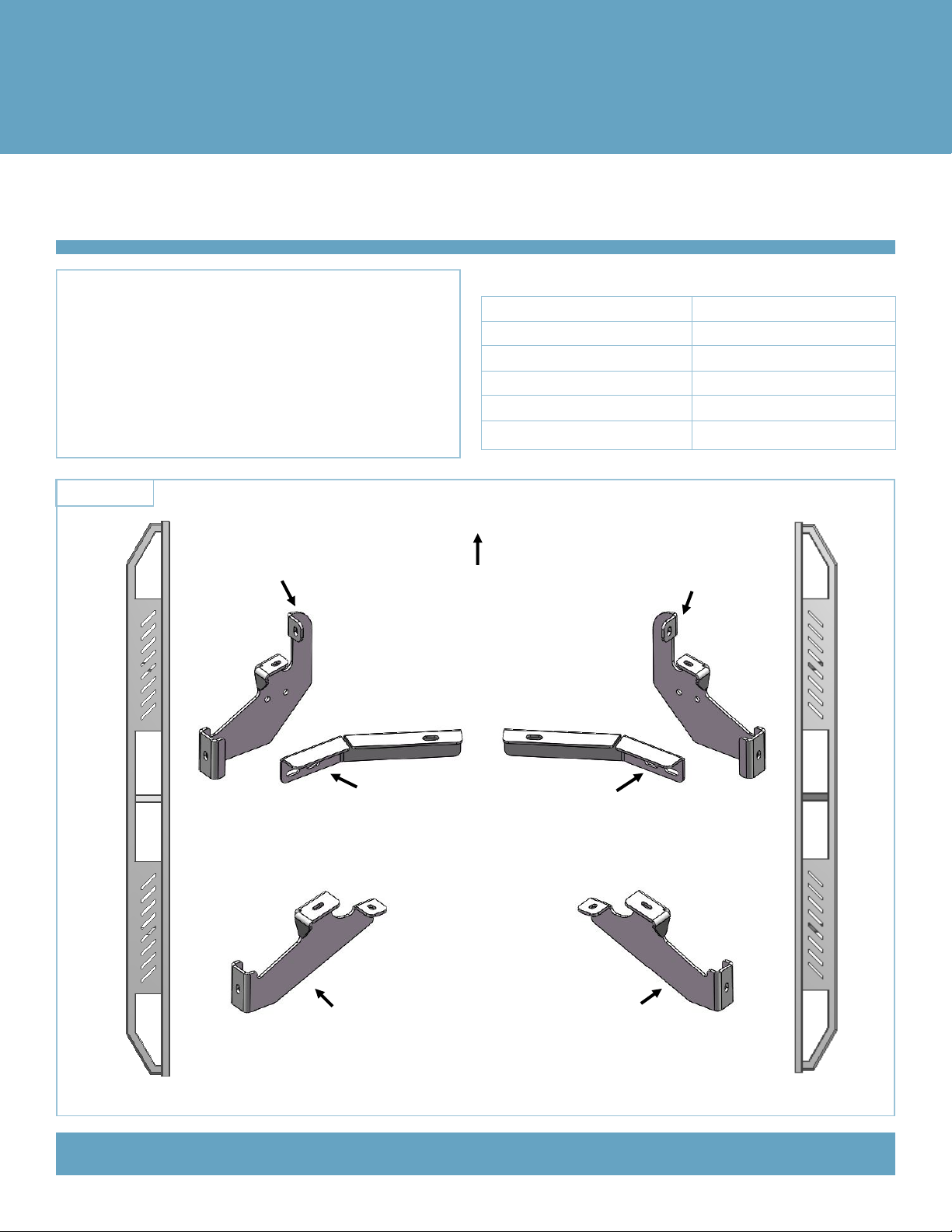
PART LIST
Driver Front Mounting
Bracket (DFM)
X1
X1
Fastener Size Tightening Torque (ft-lbs)
6mm 6-7
8mm 16-18
10mm 31-32
12mm 56-58
14mm 92-94
Front
Passenger Front Mounting Bracket (PFM)
X1
X1
Driver Side Step Bar
Driver Front Support
Bracket (DFS)
Driver Rear Mounting Bracket (DRM)
Customer Support: info@iarmorauto.com
X1
Passenger Front Support Bracket (PFS)
X1
Passenger Rear Mounting Bracket (PRM)
Passenger Side Step Bar
1
Rev. 20201201

®
iArmor
X2
X16
X1
M10X40 Bolt Plate
X4
M8X1.25-35mm Hex
Bolt
X8
M8X1.25 Hex Nut
X4
M8 Rivet Insert
Installation Tool
U Bracket
The instruction here is for your reference only. We strongly
recommend the professional installer for best result. We are not
responsible for any damage caused by the installation.
M10X1.5 Hex Nut
M8 Lock Washer
STEP 1
X2
X20
X2
M10 Large Flat Washer
M8X1.25-25mm Hex
Bolt
X2
M10 Lock Washer
X8
M8 Large Flat Washer
X4
X2
M8X1.25 Rivet Insert
M8X1.25-55mm Carriage Bolt
STEP 2
Select the Driver Front Mounting Bracket (DFM). Attach the
Bracket to the two threaded holes using the provided (2)
M8X1.25 -25mm Hex Bolts, (2) M8 Lock Washers and (2) M8
Large Flat Washers. Snug but do not tighten hardware at this
time, (Fig 2).
X8
Spacer
Starting on the driver side front, locate the two factory 8mm
threaded holes, one located in the bottom of the floor panel and
the second in the side of the inner body panel (Fig 1).
IMPORTANT: All factory threaded holes may be covered
with rubber plugs or undercoating. Scrape off any excess
undercoating from mounting surfaces.
Locate (2) Factory 8mm
Threaded Holes
(Fig 1) Driver Side Front Mounting Location
Customer Support: info@iarmorauto.com
Front
(2) M8X1.25 -25mm Hex Bolts
(2) M8 Lock Washers
(2) M8 Large Flat Washers
(Fig 2) Driver Front Mounting Bracket (DFM) Installed
STEP 3
Select (1) M10x40 Bolt Plate. Insert the Bolt Plate into the factory hole in the bottom of the frame channel, (Fig 3). Rotate the
2
Rev. 20201201