

Page 1

ROBO Cylinder
Linear Servo Type
Rod Type
Instruction Manual
Third Edition
RCL-RA1L, RA2L, RA3L
IAI America, Inc.
Page 2

Page 3

Please Read Before Use
Thank you for purchasing our product.
This Instruction Manual explains the handling methods, structure and maintenance of this product,
among others, providing the information you need to know to use the product safely.
Before using the product, be sure to read this manual and fully understand the contents explained
herein to ensure safe use of the product.
The CD or DVD that comes with the product contains instruction manuals for IAI products.
When using the product, refer to the necessary portions of the applicable instruction manual by
printing them out or displaying them on a PC.
After reading the Instruction Manual, keep it in a convenient place so that whoever is handling this
product can reference it quickly when necessary.
[Important]
x This Instruction Manual is original.
x This product is not to be used for any other purpose from what is noted in this Instruction Manual.
IAI shall not be liable whatsoever for any loss or damage arising from the result of using the
product for any other purpose from what is noted in the manual.
x The information contained in this Instruction Manual is subject to change without notice for the
purpose of production improvement.
x If you have any question or finding regarding the information contained in this Instruction Manual,
contact our customer center or our sales office near you.
x Using or copying all or a part of this Instruction Manual without permission is prohibited.
x The company names, names of products and trademarks of each company shown in the
sentences are registered trademarks.
Page 4

Page 5

Table of Contents
Safety Guide············································································································ 1
Caution in Handling ·································································································8
International Standards Compliances ······································································9
Names of the Parts································································································ 10
1. Specifications Check······················································································· 11
1.1 Checking the Product························································································ 11
1.1.1 Components ······························································································· 11
1.1.2 Operating Manuals for the Controllers Related to this Product ·················· 11
1.1.3 How to Read the Model Nameplate ··························································· 12
1.1.4 How to Read the Model Number ································································12
1.2 Specification······································································································13
1.2.1 Speed ········································································································· 13
1.2.2 Relationship between Transportable Weight and Acceleration Speed ·······13
1.2.3 Rated Thrust and Transient Maximum Thrust ············································14
1.2.4 Encoder Resolution ····················································································14
1.2.5 No. of Encoder Pulses················································································14
1.2.6 Positioning Repeatability ············································································14
1.2.7 Relationship between Current Limiting Value and Pressing Force ············14
1.3 Option················································································································ 15
1.3.1 Brake (with brake box) (Model No. : B) ······················································15
1.3.2 Brake (with no brake box) (Model No. : BN)···············································15
1.4 Motor • Encoder Cables ····················································································16
1.4.1 Motor • Encoder Integrated Cables
(For AMEC, ASEP) CB-APSEP-MPAƑƑƑ ······································16
1.4.2 Motor • Encoder Integrated Cables (with brake cable)
(For AMEC, ASEP) CB-ACS-MPBAƑƑƑ ········································ 17
1.4.3 Motor • Encoder Integrated Cables
(For ACON, ASEL) CB-ACS-MPAƑƑƑ ···········································18
1.4.4 Motor • Encoder Integrated Cables (with brake cable)
(For ACON, ASEL) CB-ACS-MPBAƑƑƑ········································· 19
2. Installation······································································································· 20
2.1 Transportation ··································································································· 21
2.2 Installation and Storage • Preservation Environment ········································22
2.3 How to Install····································································································· 23
2.3.1 General Rules on Installation ·····································································23
2.3.2 Installing the Main Body ·············································································24
2.3.3 Attachment of Transported Objects····························································28
3. Connecting with the Controller········································································ 29
3.1 Brake Box Installation for Brake-Equipped Type···············································31
3.1.1 Brake Box RCB-110-RCLB-0 ··································································31
3.1.2 Procedures to Connect and Start Brake Box·············································· 32
Page 6

4. Operational Conditions ··················································································· 36
4.1 Acceleration of the Setting ················································································36
4.2 Reference for Cycle Time··················································································37
4.3 Setting of Current Limit Value at Pressing Operation········································38
4.4 Vibration • Resonance Noise Control································································40
5. Maintenance Inspection··················································································41
5.1 Inspection Items and Schedule ·········································································41
5.2 External Visual Inspection·················································································41
5.3 Cleaning ············································································································ 41
6. External Dimensions·······················································································42
6.1 RCL-RA1L without brake type ········································································42
6.2 RCL-RA1L equipped with brake (option) ························································42
6.3 RCL-RA2L without brake type ········································································43
6.4 RCL-RA2L equipped with brake (option) ························································43
6.5 RCL-RA3L without brake type ········································································44
6.6 RCL-RA3L equipped with brake (option) ························································44
7. Life·················································································································· 45
8. Warranty ········································································································· 46
8.1 Warranty Period ································································································ 46
8.2 Scope of the Warranty·······················································································46
8.3 Honoring the Warranty ······················································································46
8.4 Limited Liability·································································································· 46
8.5 Conditions of Conformance with Applicable Standards/Regulations,
Etc., and Applications ······· 47
8.6 Other Items Excluded from Warranty ································································47
Change History······································································································ 48
Page 7

1
Safety Guide
“Safety Guide” has been written to use the machine safely and so prevent personal injury or
property damage beforehand. Make sure to read it before the operation of this product.
Safety Precautions for Our Products
The common safety precautions for the use of any of our robots in each operation.
No.
Operation
Description
Description
1 Model
Selection
Ɣ This product has not been planned and designed for the application
where high level of safety is required, so the guarantee of the protection
of human life is impossible. Accordingly, do not use it in any of the
following applications.
1) Medical equipment used to maintain, control or otherwise affect
human life or physical health.
2) Mechanisms and machinery designed for the purpose of moving or
transporting people (For vehicle, railway facility or air navigation
facility)
3) Important safety parts of machinery (Safety device, etc.)
Ɣ Do not use the product outside the specifications. Failure to do so may
considerably shorten the life of the product.
Ɣ Do not use it in any of the following environments.
1) Location where there is any inflammable gas, inflammable object or
explosive
2) Place with potential exposure to radiation
3) Location with the ambient temperature or relative humidity exceeding
the specification range
4) Location where radiant heat is added from direct sunlight or other
large heat source
5) Location where condensation occurs due to abrupt temperature
changes
6) Location where there is any corrosive gas (sulfuric acid or
hydrochloric acid)
7) Location exposed to significant amount of dust, salt or iron powder
8) Location subject to direct vibration or impact
Ɣ For an actuator used in vertical orientation, select a model which is
equipped with a brake. If selecting a model with no brake, the moving
part may drop when the power is turned OFF and may cause an
accident such as an injury or damage on the work piece.
Page 8

2
No.
Operation
Description
Description
2 Transportation Ɣ When carrying a heavy object, do the work with two or more persons or
utilize equipment such as crane.
Ɣ When the work is carried out with 2 or more persons, make it clear who
is to be the leader and who to be the follower(s) and communicate well
with each other to ensure the safety of the workers.
Ɣ When in transportation, consider well about the positions to hold, weight
and weight balance and pay special attention to the carried object so it
would not get hit or dropped.
Ɣ Transport it using an appropriate transportation measure.
The actuators available for transportation with a crane have eyebolts
attached or there are tapped holes to attach bolts. Follow the
instructions in the instruction manual for each model.
Ɣ Do not step or sit on the package.
Ɣ Do not put any heavy thing that can deform the package, on it.
Ɣ When using a crane capable of 1t or more of weight, have an operator
who has qualifications for crane operation and sling work.
Ɣ When using a crane or equivalent equipments, make sure not to hang a
load that weighs more than the equipment’s capability limit.
Ɣ Use a hook that is suitable for the load. Consider the safety factor of the
hook in such factors as shear strength.
Ɣ Do not get on the load that is hung on a crane.
Ɣ Do not leave a load hung up with a crane.
Ɣ Do not stand under the load that is hung up with a crane.
3 Storage and
Preservation
Ɣ The storage and preservation environment conforms to the installation
environment. However, especially give consideration to the prevention
of condensation.
Ɣ Store the products with a consideration not to fall them over or drop due
to an act of God such as earthquake.
4 Installation
and Start
(1) Installation of Robot Main Body and Controller, etc.
Ɣ Make sure to securely hold and fix the product (including the work part).
A fall, drop or abnormal motion of the product may cause a damage or
injury.
Also, be equipped for a fall-over or drop due to an act of God such as
earthquake.
Ɣ Do not get on or put anything on the product. Failure to do so may cause
an accidental fall, injury or damage to the product due to a drop of
anything, malfunction of the product, performance degradation, or
shortening of its life.
Ɣ When using the product in any of the places specified below, provide a
sufficient shield.
1) Location where electric noise is generated
2) Location where high electrical or magnetic field is present
3) Location with the mains or power lines passing nearby
4) Location where the product may come in contact with water, oil or
chemical droplets
Page 9

3
No.
Operation
Description
Description
(2) Cable Wiring
Ɣ Use our company’s genuine cables for connecting between the actuator
and controller, and for the teaching tool.
Ɣ Do not scratch on the cable. Do not bend it forcibly. Do not pull it. Do not
coil it around. Do not insert it. Do not put any heavy thing on it. Failure to
do so may cause a fire, electric shock or malfunction due to leakage or
continuity error.
Ɣ Perform the wiring for the product, after turning OFF the power to the
unit, so that there is no wiring error.
Ɣ When the direct current power (+24V) is connected, take the great care
of the directions of positive and negative poles. If the connection
direction is not correct, it might cause a fire, product breakdown or
malfunction.
Ɣ Connect the cable connector securely so that there is no disconnection
or looseness. Failure to do so may cause a fire, electric shock or
malfunction of the product.
Ɣ Never cut and/or reconnect the cables supplied with the product for the
purpose of extending or shortening the cable length. Failure to do so
may cause the product to malfunction or cause fire.
4 Installation
and Start
(3) Grounding
Ɣ The grounding operation should be performed to prevent an electric
shock or electrostatic charge, enhance the noise-resistance ability and
control the unnecessary electromagnetic radiation.
Ɣ For the ground terminal on the AC power cable of the controller and the
grounding plate in the control panel, make sure to use a twisted pair
cable with wire thickness 0.5mm
2
(AWG20 or equivalent) or more for
grounding work. For security grounding, it is necessary to select an
appropriate wire thickness suitable for the load. Perform wiring that
satisfies the specifications (electrical equipment technical standards).
Ɣ Perform Class D Grounding (former Class 3 Grounding with ground
resistance 100: or below).
Page 10

4
No.
Operation
Description
Description
4 Installation
and Start
(4) Safety Measures
Ɣ When the work is carried out with 2 or more persons, make it clear who
is to be the leader and who to be the follower(s) and communicate well
with each other to ensure the safety of the workers.
Ɣ When the product is under operation or in the ready mode, take the
safety measures (such as the installation of safety and protection fence)
so that nobody can enter the area within the robot’s movable range.
When the robot under operation is touched, it may result in death or
serious injury.
Ɣ Make sure to install the emergency stop circuit so that the unit can be
stopped immediately in an emergency during the unit operation.
Ɣ Take the safety measure not to start up the unit only with the power
turning ON. Failure to do so may start up the machine suddenly and
cause an injury or damage to the product.
Ɣ Take the safety measure not to start up the machine only with the
emergency stop cancellation or recovery after the power failure. Failure
to do so may result in an electric shock or injury due to unexpected
power input.
Ɣ When the installation or adjustment operation is to be performed, give
clear warnings such as “Under Operation; Do not turn ON the power!”
etc. Sudden power input may cause an electric shock or injury.
Ɣ Take the measure so that the work part is not dropped in power failure or
emergency stop.
Ɣ Wear protection gloves, goggle or safety shoes, as necessary, to secure
safety.
Ɣ Do not insert a finger or object in the openings in the product. Failure to
do so may cause an injury, electric shock, damage to the product or fire.
Ɣ When releasing the brake on a vertically oriented actuator, exercise
precaution not to pinch your hand or damage the work parts with the
actuator dropped by gravity.
5 Teaching Ɣ When the work is carried out with 2 or more persons, make it clear who
is to be the leader and who to be the follower(s) and communicate well
with each other to ensure the safety of the workers.
Ɣ Perform the teaching operation from outside the safety protection fence,
if possible. In the case that the operation is to be performed unavoidably
inside the safety protection fence, prepare the “Stipulations for the
Operation” and make sure that all the workers acknowledge and
understand them well.
Ɣ When the operation is to be performed inside the safety protection
fence, the worker should have an emergency stop switch at hand with
him so that the unit can be stopped any time in an emergency.
Ɣ When the operation is to be performed inside the safety protection
fence, in addition to the workers, arrange a watchman so that the
machine can be stopped any time in an emergency. Also, keep watch on
the operation so that any third person can not operate the switches
carelessly.
Ɣ Place a sign “Under Operation” at the position easy to see.
Ɣ When releasing the brake on a vertically oriented actuator, exercise
precaution not to pinch your hand or damage the work parts with the
actuator dropped by gravity.
* Safety protection Fence : In the case that there is no safety protection
fence, the movable range should be indicated.
Page 11

5
No.
Operation
Description
Description
6 Trial
Operation
Ɣ When the work is carried out with 2 or more persons, make it clear who
is to be the leader and who to be the follower(s) and communicate well
with each other to ensure the safety of the workers.
Ɣ After the teaching or programming operation, perform the check
operation one step by one step and then shift to the automatic
operation.
Ɣ When the check operation is to be performed inside the safety
protection fence, perform the check operation using the previously
specified work procedure like the teaching operation.
Ɣ Make sure to perform the programmed operation check at the safety
speed. Failure to do so may result in an accident due to unexpected
motion caused by a program error, etc.
Ɣ Do not touch the terminal block or any of the various setting switches in
the power ON mode. Failure to do so may result in an electric shock or
malfunction.
7 Automatic
Operation
Ɣ Check before starting the automatic operation or rebooting after
operation stop that there is nobody in the safety protection fence.
Ɣ Before starting automatic operation, make sure that all peripheral
equipment is in an automatic-operation-ready state and there is no
alarm indication.
Ɣ Make sure to operate automatic operation start from outside of the
safety protection fence.
Ɣ In the case that there is any abnormal heating, smoke, offensive smell,
or abnormal noise in the product, immediately stop the machine and
turn OFF the power switch. Failure to do so may result in a fire or
damage to the product.
Ɣ When a power failure occurs, turn OFF the power switch. Failure to do
so may cause an injury or damage to the product, due to a sudden
motion of the product in the recovery operation from the power failure.
Page 12

6
No.
Operation
Description
Description
8 Maintenance
and
Inspection
Ɣ When the work is carried out with 2 or more persons, make it clear who
is to be the leader and who to be the follower(s) and communicate well
with each other to ensure the safety of the workers.
Ɣ Perform the work out of the safety protection fence, if possible. In the
case that the operation is to be performed unavoidably inside the safety
protection fence, prepare the “Stipulations for the Operation” and make
sure that all the workers acknowledge and understand them well.
Ɣ When the work is to be performed inside the safety protection fence,
basically turn OFF the power switch.
Ɣ When the operation is to be performed inside the safety protection
fence, the worker should have an emergency stop switch at hand with
him so that the unit can be stopped any time in an emergency.
Ɣ When the operation is to be performed inside the safety protection
fence, in addition to the workers, arrange a watchman so that the
machine can be stopped any time in an emergency. Also, keep watch on
the operation so that any third person can not operate the switches
carelessly.
Ɣ Place a sign “Under Operation” at the position easy to see.
Ɣ For the grease for the guide or ball screw, use appropriate grease
according to the Instruction Manual for each model.
Ɣ Do not perform the dielectric strength test. Failure to do so may result in
a damage to the product.
Ɣ When releasing the brake on a vertically oriented actuator, exercise
precaution not to pinch your hand or damage the work parts with the
actuator dropped by gravity.
Ɣ The slider or rod may get misaligned OFF the stop position if the servo
is turned OFF. Be careful not to get injured or damaged due to an
unnecessary operation.
Ɣ Pay attention not to lose the cover or untightened screws, and make
sure to put the product back to the original condition after maintenance
and inspection works.
Use in incomplete condition may cause damage to the product or an
injury.
* Safety protection Fence : In the case that there is no safety protection
fence, the movable range should be indicated.
9 Modification
and Dismantle
Ɣ Do not modify, disassemble, assemble or use of maintenance parts not
specified based at your own discretion.
10 Disposal Ɣ When the product becomes no longer usable or necessary, dispose of it
properly as an industrial waste.
Ɣ When removing the actuator for disposal, pay attention to drop of
components when detaching screws.
Ɣ Do not put the product in a fire when disposing of it.
The product may burst or generate toxic gases.
11 Other Ɣ Do not come close to the product or the harnesses if you are a person
who requires a support of medical devices such as a pacemaker. Doing
so may affect the performance of your medical device.
Ɣ See Overseas Specifications Compliance Manual to check whether
complies if necessary.
Ɣ For the handling of actuators and controllers, follow the dedicated
instruction manual of each unit to ensure the safety.
Page 13
7
Alert Indication
The safety precautions are divided into “Danger”, “Warning”, “Caution” and “Notice” according to the
warning level, as follows, and described in the Instruction Manual for each model.
Level Degree of Danger and Damage Symbol
Danger
This indicates an imminently hazardous situation which, if the
product is not handled correctly, will result in death or serious
injury.
Danger
Warning
This indicates a potentially hazardous situation which, if the
product is not handled correctly, could result in death or serious
injury.
Warning
Caution
This indicates a potentially hazardous situation which, if the
product is not handled correctly, may result in minor injury or
property damage.
Caution
Notice
This indicates lower possibility for the injury, but should be kept to
use this product properly.
Notice
Page 14
8
Caution in Handling
1. Ensure use of the product in the specified conditions, environments and ranges.
Operation out of the specified conditions could cause a drop in performance or malfunction
of the product.
䎃
2. Do not conduct any treatment or operation that is not stated in this instruction
manual.䎃
䎃
3. For the wiring of the controller and actuator, use the IAI product.䎃
䎃
4. Do not attempt to establish the settings for the speed and
acceleration/deceleration above the allowable range.䎃
If the robot is operated at a speed or acceleration/deceleration exceeding the allowable value,
abnormal noise or vibration, failure, or shorter life may result.
䎃
䎃
5. About load applied to actuator䎃
Avoid rotation torque from being applied to the rod.䎃
Install a guide so the load vertical to the rod moving directions (sideway load) would not be
applied.
䎃
䎃
䎃
䎃
䎃
6. Make sure to attach the actuator properly by following this operation manual.䎃
Using the product with the actuator not being certainly retained or affixed may cause abnormal
noise, vibration, malfunction or shorten the product life.
䎃
䎃
7. Pay attention to temperature rise.䎃
In case movement of rod is continuously conducted or pressing operation is continued for long
time, the temperature on the unit body and the rod will rise. Please be careful.
䎃
䎃
8. Make sure to keep the rod in stop condition for a short while (approx. 3sec)
straight after the power is turned on or software reset.䎃
There is a magnetic pole detection process of the motor when the power is turned on or at
software reset. It may get detected as an error if the rod moves during this magnetic pole
detection.
䎃
䎃
9. This actuator requires a home-return operation after startup.䎃
The home position is one point at the side of rod being pulled in. (Can not be changed.)
Make sure to construct the system with no interference around the home position.䎃
䎃
Page 15

9
International Standards Compliances
This actuator complies with the following overseas standard.
Refer to Overseas Standard Compliance Manual (ME0287) for more detailed information.
RoHS Directive CE Marking UL
c ¯ ¯
Page 16
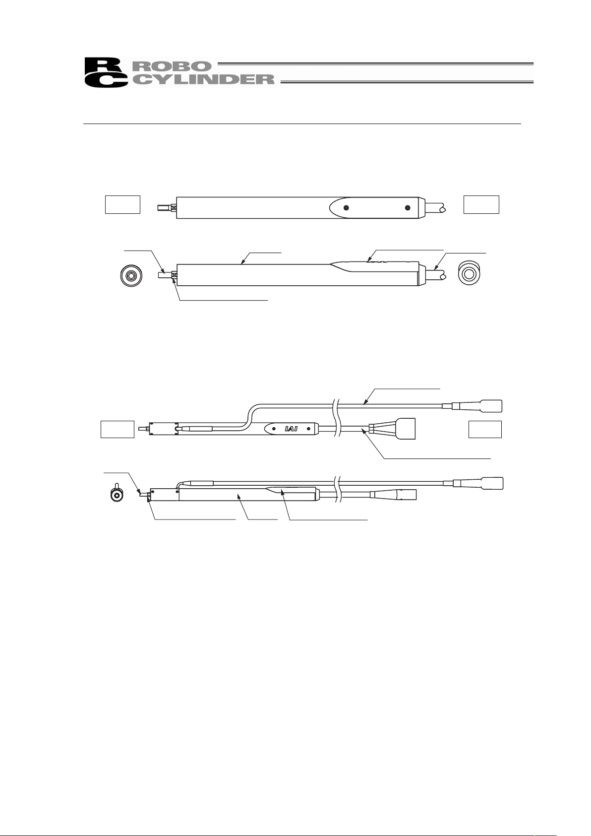
10
Names of the Parts
In this manual, the right and left sides of the actuator are expressed in the way it is placed
horizontally as shown in the figure below, and is looked at from the motor side.
Ɣ Without brake type
Rod
Width across flats
Pipe
Cable
Encoder cover
Front Rear
Ɣ With brake type
Rear
Front
Rod
Brake cable
Motor, Encoder cable
Width across flats Pipe
Encoder cover
Page 17

11
1. Specifications Check
1.1 Checking the Product
The standard configuration of this product is comprised of the following parts.
See the component list for the details of the enclosed components. If you find any broken or
missing parts, contact your local IAI distributor.
1.1.1 Components
No. Name Model number Quantity Remarks
1 Main Unit
Refer to “How to Read the
Model Nameplate” and “How
to Read the Model Number.”
1
Accessories
2
Motor • encoder cables
(Note 1)
1 set
3 In-house made seals 1
4 First Step Guide
1
5 Instruction Manual (DVD)
1
6 Safety Guide
1
Note1 The motor • encoder cables differ between the standard model and robot cable.
[Refer to 1.4 “Motor • Encoder Cables.”]
1.1.2 Operating Manuals for the Controllers Related to this Product
No. Name Control No.
1 Instruction Manual for ACON-C/CG Controller ME0176
2 Instruction Manual for ACON-CY Controller ME0167
3 Instruction Manual for ACON-SE Controller ME0171
4 Instruction Manual for ACON-PL/PO Controller ME0166
5 Instruction Manual for ASEL Controller MJ0165
6 Instruction Manual for MEC Controller ME0245
7 Instruction Manual for PSEP/ASEP/DSEP Controller MJ0216
8 Instruction Manual for MSEP Controller ME0299
9
Instruction Manual for PC Software IA-101-X-MW/IA-101-X-USBMW
ME0154
10 Instruction Manual for PC Software RCM-101-MW/ RCM-101-USB ME0155
11 Instruction Manual for MEC Software ME0248
12 Instruction Manual for Teaching Pendant CON-T/TG ME0178
13
Instruction Manual for Teaching Pendant SEL-T/TD
ME0183
14 Instruction Manual for Touch Panel Teaching CON-PTA/PDA/PGA ME0295
15 Instruction Manual for Teaching Pendant CON-PT/PD/PG ME0227
16 Instruction Manual for Teaching Pendant SEP-PT ME0217
17 Instruction Manual for Simple Teaching Pendant RCM-E ME0174
18 Instruction Manual for Data Setter RCM-P ME0175
19 Instruction Manual for Touch Panel Display RCM-PM-01 ME0182
1. Specications Check
Page 18

1. Specications Check
12
1.1.3 How to Read the Model Nameplate
1.1.4 How to Read the Model Number
RCL – RA1L – I – 2 – N – 25 – A1 – P – B – **
Note 1 Identification for IAI use only : It may be displayed for IAI use. It is not a code to show
the model type.
Series
<Type>
Thin and small slim type
RA1L
RA2L
RA3L
<Encoder Type>
I : Incremental
<Motor Type>
2(2W) : RA1L
5(5W) : RA2L
10(10W) : RA3L
<Lead>
N : With no feeding screw
Identification for IAI use only
(Note1)
<Options>
B : With Brake
(with brake box)
BN : With Brake
(with no brake box)
<Cable length>
N : None
P : 1m
S : 3m
M : 5m
XƑƑ : Length Specification
(Example : X07=7m)
<Controller>
A1 : ACON
: RACON
: ASEL
A3 : AMEC
ASEP
MSEP
<Stroke>
[Refer to 6 “External Dimensions”]
Model
Serial Numbe
r
MODEL RCL-RA1L-I-2-N-25-A1-P
SERIAL No.800061910
MADE IN JAPAN
Page 19

13
1.2 Specification
1.2.1 Speed
Type Maximum speed [mm/s]
RA1L 300
RA2L 340
RA3L 450
1.2.2 Relationship between Transportable Weight and Acceleration Speed
The acceleration is determined by the transported weight and the duty.
From the table below, determine the acceleration from Continuous Operation (Duty 100%) when
the duty is over 70% and up to 100%, and Duty 70% or less when it is 70% or below.
Transportable Weight [kg]
Continuous Operation
(Duty 100%)
Duty 70% or less
Type
Max.
Acceleration
Speed
[G]
Horizontal Vertical Horizontal Vertical
0.1
0.3
0.5
0.5 0.42
0.5
1.0 0.2
0.1
0.25
0.1
1.5 0.11 – 0.15 –
RA1L
2.0 0.07 – 0.1 –
0.1
0.3
1.0
0.5 0.85
1.0
1.0 0.4
0.2
0.5
0.2
1.5 0.24 – 0.3 –
RA2L
2.0 0.15 – 0.2 –
0.1
0.3
2.0
0.5 1.6
2.0
1.0 0.78
0.4
1.0
0.4
1.5 0.46 – 0.6 –
RA3L
2.0 0.3 – 0.4 –
Operating time
Duty =
Operating time + Stop time
× 100
Caution: Do not have the settings of acceleration/deceleration exceeding the rated values. It
may cause vibration, malfunction or shortened life.
1. Specications Check
Page 20

1. Specications Check
14
1.2.3 Rated Thrust and Transient Maximum Thrust
Type Rated Thrust [N] Transient Maximum Thrust [N]
RA1L 2.5 10
RA2L 5 18
RA3L 10 30
1.2.4 Encoder Resolution
0.042mm
1.2.5 No. of Encoder Pulses
RA1L 715
RA2L 855
RA3L 1145
1.2.6 Positioning Repeatability
±0.1mm
* It does not include the consideration of time-dependent change as it is used.
1.2.7 Relationship between Current Limiting Value and Pressing Force
[Refer to 4.3 Setting of Current Limit Value at Pressing Operation]
Page 21

15
1.3 Option
1.3.1 Brake (with brake box) (Model No. : B)
This is a function to hold the rod so it would not drop when the power or the servo is turned
OFF in the condition that the actuator is installed in the vertical orientation. It is to be used to
avoid damaging the attached objects by the rod being dropped.
1.3.2 Brake (with no brake box) (Model No. : BN)
This is a function to hold the rod so it would not drop when the power or the servo is turned
OFF in the condition that the actuator is installed in the vertical orientation. It is to be used to
avoid damaging the attached objects by the rod being dropped.
It is the model code that you may indicate when purchasing only the unit body equipped with
a brake in such cases as repair.
Specifications Related to Brake-Equipped Type
Type
Retaining Load
(Note 1)
(Vertical
(Note 2)
)
Retaining
Precision
(Note 1)
Times of Brake for
Life End
RA1L 0.1 [kg]
RA2L 0.2 [kg]
RA3L 0.4 [kg]
1mm or less 100,000 times
Note 1 This may change due to many causes such as the condition of rod surface. Especially in
an environment that the product can involve oil or foreign objects, the values would not
be guaranteed.
Note 2 Guarantee may not be performed in an installing orientation other than vertical.
1. Specications Check
Page 22

1. Specications Check
16
1.4 Motor • Encoder Cables
1.4.1 Motor • Encoder Integrated Cables (For AMEC, ASEP)
CB-APSEP-MPAƑƑƑ
Mechanical side
Controller side
Electric
wire color
Signal
name
Pin No. Pin No.
Signal
name
Electric
wire color
Black U A1 1 U Black
White V B1 2 V White
Brown W A2 5 W Brown
Green – B2 3 – Green
Yellow – A3 4 – Yellow
Red – B3 6 – Red
Orange BK+ A4 7 BK+ Orange
Gray BK- B4 8 BK- Gray
White A+ A6 11 A+ White
Yellow A- B6 12 A- Yellow
Red B+ A7 13 B+ Red
Green B- B7 14 B- Green
Black Z+ A8 15 Z+ Black
Brown Z- B8 16 Z- Brown
Black LS+ A5 9 LS+ Black
Brown LS- B5 10 LS- Brown
Green GNDLS A9 20 GNDLS Green
Red VPS B9 18 VPS Red
White VCC A10 17 VCC White
Yellow GND B10 19 GND Yellow
– A11 21 –
shield FG B11 24 FG shield
22 –
23 –
Page 23

17
1.4.2 Motor • Encoder Integrated Cables (with brake cable) (For AMEC, ASEP)
CB-APSEP-MPBAƑƑƑ
500±20
Connected to the Brake Box
Electric
wire
color
Signal
name
Pin No. Pin No.
Signal
name
Electric
wire
color
Black
U A1 1 U
Black
White
V B1 2 V
White
Brown
W A2 5 W
Brown
Green –
B2 3
– Green
Yellow –
A3 4
– Yellow
Red –
B3 6
– Red
Orange
BK+ A4 7 BK+
Orange
Gray
BK- B4 8 BK-
Gray
White
A+ A6 11 A+
White
Yellow
A- B6 12 A-
Yellow
Red
B+ A7 13 B+
Red
Green
B- B7 14 B-
Green
Black
Z+ A8 15 Z+
Black
Brown
Z- B8 16 Z-
Brown
Black
LS+ A5 9 LS+
Black
Brown
LS- B5 10 LS-
Brown
Green
GNDLS A9 20 GND
LS
Green
Red
VPS B9 18 VPS
Red
White
VCC A10 17 VCC
White
Yellow
GND B10 19 GND
Yellow
–
A11 21
–
shield
FG B11 24 FG
shield
22
–
23
–
Brown
BK+ 1 7 BK+
Brown
Blue
BK- 2 8 BK-
Blue
1. Specications Check
Page 24

1. Specications Check
18
1.4.3 Motor • Encoder Integrated Cables (For ACON, ASEL)
CB-ACS-MPAƑƑƑ
(Front View) (Front View)
Mechanical side
Controller side
Electric wire
color
Signal
name
Pin No. Pin No.
Signal
name
Electric wire
color
Red U A1 1 U Red
Yellow V B1 2 V Yellow
Black W A2 3 W Black
–
B2
– A3
Pin No.
Signal
name
Electric wire
color
– B3 4 – Yellow
3 –
2 –
Yellow (Redx) BK+ A4 16 BK+ Yellow (Redx)
Yellow (Bluex) BK- B4 15 BK- Yellow (Bluex)
Pink(Redx) LS+ A5 18 LS+ Pink(Redx)
Pink(Bluex) LS- B5 17 LS- Pink(Bluex)
White(Redx) A+ A6 14 A+ White(Redx)
White(Bluex) A- B6 13 A- White(Bluex)
Orange(Redx) B+ A7 12 B+ Orange(Redx)
Orange(Bluex) B- B7 11 B- Orange(Bluex)
Gray(Redx) Z+ A8 10 Z+ Gray(Redx)
Gray(Bluex) Z- B8 9 Z- Gray(Bluex)
Orange (Red㨯continuous)
– A9 8 –
Orange (Red㨯continuous)
Orange (Bluexcontinuous)
/PS B9 7 /PS
Orange (Bluexcontinuous)
Gray (Redxcontinuous)
VCC A10 6 VCC
Gray (Redxcontinuous)
Gray (Bluexcontinuous)
GND B10 5 GND
Gray (Bluexcontinuous)
– A11 –
shield FG B11 1 FG shield
Page 25

19
1.4.4 Motor • Encoder Integrated Cables (with brake cable) (For ACON, ASEL)
CB-ACS-MPBAƑƑƑ
500±20
Connected to the Brake Box
Electric wire
color
Signal
name
Pin No. Pin No.
Signal
name
Electric wire
color
Red U A1 1 U Red
Yellow V B1 2 V Yellow
Black W A2 3 W Black
–
B2
– A3
Pin No.
Signal
name
Electric wire
color
– B3 4 – Yellow
3 –
2 –
Yellow (Redx) BK+ A4 16 BK+ Yellow (Redx)
Yellow (Bluex) BK- B4 15 BK- Yellow (Bluex)
Pink(Redx) LS+ A5 18 LS+ Pink(Redx)
Pink(Bluex) LS- B5 17 LS- Pink(Bluex)
White(Redx) A+ A6 14 A+ White(Redx)
White(Bluex) A- B6 13 A- White(Bluex)
Orange(Redx) B+ A7 12 B+ Orange(Redx)
Orange(Bluex) B- B7 11 B- Orange(Bluex)
Gray(Redx) Z+ A8 10 Z+ Gray(Redx)
Gray(Bluex) Z- B8 9 Z- Gray(Bluex)
Orange (Red㨯continuous)
– A9 8 –
Orange (Red㨯continuous)
Orange (Bluexcontinuous)
/PS B9 7 /PS
Orange (Bluexcontinuous)
Gray (Redxcontinuous)
VCC A10 6 VCC
Gray (Redxcontinuous)
Gray (Bluexcontinuous)
GND B10 5 GND
Gray (Bluexcontinuous)
– A11 –
shield FG B11 1 FG shield
Brown
BK+ 1 16 BK+
Brown
Brown
BK- 2
15 BK-
Brown
1. Specications Check
Page 26

2. Installation
20
2. Installation
2.1 Transportation
[1] Handling of the Robot
Unless otherwise specified, the actuators are packaged individually.
(1) Handling the Packed Unit
y Do not damage or drop. The package is not applied with any special treatment that enables it
to resist an impact caused by a drop or crash.
y An operator should never attempt to carry a heavy package on their own. Also, use an
appropriate way for transportation.
y Keep the unit in a horizontal orientation when placing it on the ground or transporting. Follow
the instruction if there is any for the packaging condition.
y Do not step or sit on the package.
y Do not put any load that may cause a deformation or breakage of the package.
(2) Handling the Actuator After Unpacking
y Do not attempt to carry the actuator by holding a cable or move it by pulling a cable.
y Hold the base part and the bracket when transporting the actuator main body.
y Do not hit or drop the actuator during transportation.
y Do not give any excessive force to any of the sections in the actuator.
Page 27

21
[2] Handling in the Assembled Condition
This is the case when the product is delivered from our factory under a condition that it is
assembled with other actuators. The combined axes are delivered in a package that the frame
is nailed on the lumber base. The rods are fixed so they would not accidently move. The
actuators are also fixed so the tip of it would not shake due to the external vibration.
(1) How to Handle the Package
y Do not hit or drop the package. No special treatment is conducted on this package to endure
a drop or impact on it.
y Do not attempt to carry a heavy package with only one worker. Also, have an appropriate
method for transportation.
y When hanging up with ropes, support on the reinforcement frame on the bottom of the lumber
base. When bringing up the package with a forklift, also support on the bottom of the lumber
base.
y Handle with care when putting the package down to avoid impact or bounce.
y Do not step on the package.
y Do not put anything on the package that could deform or damage it.
(2) How to Handle after Unpackaged
y Fix the rod(s) so they would not accidently move during transportation.
y If the tip of an actuator is overhanging, have an appropriate way to fix it to avoid shaking due
to the external vibration. In the transportation without the tip being fixed, do not apply any
impact with 0.3G or more.
y When hanging up with ropes, have appropriate cushioning to avoid any deformation of the
actuator body. Also keep it in stable horizontal orientation. Make a fixture utilizing the
attachment holes and the tapped holes on the actuator body if necessary.
y Do not attempt to apply load on the actuators or the connector box. Also pay attention not to
pinch cables and bend or deform them forcefully.
[3] Handling in Condition of being assembled in Machinery Equipment (System)
These are some caution notes for when transporting the actuator being assembled in the
machinery equipment (system):
y Fix the rod(s) so that it would not move during transportation.
y If the tip of an actuator is overhanging, have an appropriate way to fix it to avoid shaking due
to the external vibration. In the transportation without the tip being fixed, do not apply any
impact with 0.3G or more.
y When hanging up the machinery equipment (system) with ropes, do not attempt to apply load
on the actuators or the connector box. Also pay attention not to pinch cables and bend or
deform them forcefully.
2. Installation
Page 28

2. Installation
22
2.2 Installation and Storage • Preservation Environment
[1] Installation Environment
The actuator should be installed in a location other than those specified below.
In general, the installation environment should be one in which an operator can work without
protective gear.
Also provide sufficient work space required for maintenance inspection.
y Where the actuator receives radiant heat from strong heat sources such as heat treatment
furnaces
y Where the ambient temperature exceeds the range of 0 to 40qC
y Where the temperature changes rapidly and condensation occurs
y Where the relative humidity exceeds 85% RH
y This actuator possesses the water durability of IP67 protection structure.
y Where the actuator receives direct sunlight
y Where the actuator is exposed to corrosive or combustible gases
y Where the ambient air contains a large amount of powder dust, salt or iron (at level
exceeding what is normally expected in an assembly plant)
y Where the actuator is subject to splashed oil (including oil mist or cutting fluid) or chemical
solutions
y Where the actuator receives impact or vibration
If the actuator is used in any of the following locations, provide sufficient shielding measures:
y Where noise generates due to static electricity, etc.
y Where the actuator is subject to a strong electric or magnetic field
y Where the actuator is subject to ultraviolet ray or radiation
[2] Storage • Preservation Environment
y The storage and preservation environment should comply with the same standards as those
for the installation environment. In particular, when the machine is to be stored for a long time,
pay close attention to environmental conditions so that no dew condensation forms.
y Unless specially specified, moisture absorbency protection is not included in the package
when the machine is delivered. In the case that the machine is to be stored and preserved in
an environment where dew condensation is anticipated, take the condensation preventive
measures from outside of the entire package, or directly after opening the package.
y For storage and preservation temperature, the machine withstands temperatures up to 60qC
for a short time, but in the case of the storage and preservation period of 1 month or more,
control the temperature to 50qC or less.
y Storage and preservation should be performed in the horizontal condition. In the case it is
stored in the packaged condition, follow the posture instruction if any displayed on the
package.
Page 29

23
2.3 How to Install
This chapter explains how to install the actuator on your mechanical system.
2.3.1 General Rules on Installation
{ : Possible u : Not possible
Horizontal
installation
Vertical
installation
Sideway
installation
Ceiling mount
installation
{ { { {
Installation Orientation
Horizontal Vertical Sideway Ceiling Mount
2. Installation
Page 30

2. Installation
24
2.3.2 Installing the Main Body
[1] Mounting Method
Fixation to a mating component with a profile of hole since the body is in a cylindrical profile.
φ
d
B
A
Caution label
Dimensions for Body Attachment
Type
O.D. of Pipe
Id (tolerance)
Pipe fixable range
A
Available range for
screw fixing type B
RA1L 16 (0/-0.1) 90 30
RA2L 20 (0/-0.1) 115 40
RA3L 25 (0/-0.1) 164 55
Recommended Fixing Method
Clamping (split clamp)
Clamp with a profile of hole that suits the pipe.
Do not attempt to clamp with a flat plate, nor a profile of the hole, because it may deform the pipe.
Page 31

25
About Force to Tighten Pipe
Keep on tightening up the clamp bolts, and hold it at the tightening torque that is the minimum to
retain the pipe.
The table below shows the reference of clamping force to retain the pipe. Do no attempt to clamp
the pipe with force more than what is stated.
Note that the force applied to the pipe differs due to the profile or stiffness of the used bracket, size
of clamping bolts or tightening torque.
Pipe Clamping Force (Reference value)
Type Clamping force (Reference value)
RA1L 1,00 [N] (100kg) or less
RA2L 1,500 [N] (150kg) or less
RA3L 2,000 [N] (200kg) or less
Caution: With excessive force to tighten the pipe, the pipe may get deformed, which may result
in an operation error or malfunction.
Other Methods to Attach
When Using Fixing Screws (set screws);
When using the fixing screws, deformation is big in spots where the screws are touching the
actuator compared to clamping. Make sure to conduct attachment following Available range for
screw fixing type B in “Dimensions for Body Attachment” mentioned in “2.3.2 [1] Mounting Method”.
Also select fixing screws with small dimension and affix at several points.
In case of tightening with fixing screws with big dimension, big axial force may get applied to the
pipe, resulting in a big deformation.
Tightening torque of the cap screw (Reference value)
Cap screw size Tightening torque [N•m]
M2.5 0.18 or less
M3 0.32 or less
Caution: Tightening screws with excessive force may cause a deformation on the pipe, which
may cause an operation error or malfunction.
2. Installation
Page 32

2. Installation
26
[2] Mounting Bracket
As an attachment bracket, the following general-purposed products can be used.
Please contact directly to the supplier for each bracket.
(1) Shaft Bracket
Manufacturer : IWATA MFG.CO.,LTD.
zRA1L zRA2L
Model Number : B16CP4 Model Number : B20CP4
zRA3L
Model Number : B25CP4
(2) Maru-Pijon
Manufacturer : MIYOSHI PIJON CO.,LTD.
zRA1L zRA2L
Model Number : PN600 Model Number : PQ600
zRA3L
Model Number : PH600
φ 44
28
14.2
12
M4 bolt
φ 48
33
12
14.2
M4 bolt
φ 53
12
14.2
38
M4 bolt
40
20
42
14
52
M5 bolt
36
18
38
14
48
M5 bolt
50
64
17
43
20
M6 bolt
Page 33

27
45
25
15
30
22
51
25
24
40
32
24
40
32
58
30
M5 bolt
M6 bolt
M6 bolt
(3) Shaft Holder
Manufacturer : MISUMI Corporation
zRA1L zRA2L
Model Number : SHKSBT16 Model Number : SHKSBT20
zRA3L
Model Number : SHKSBT25
Caution: Make sure to follow the specified tightening torque when clamping the body. Not
doing so may damage the actuator.
2. Installation
Page 34

2. Installation
28
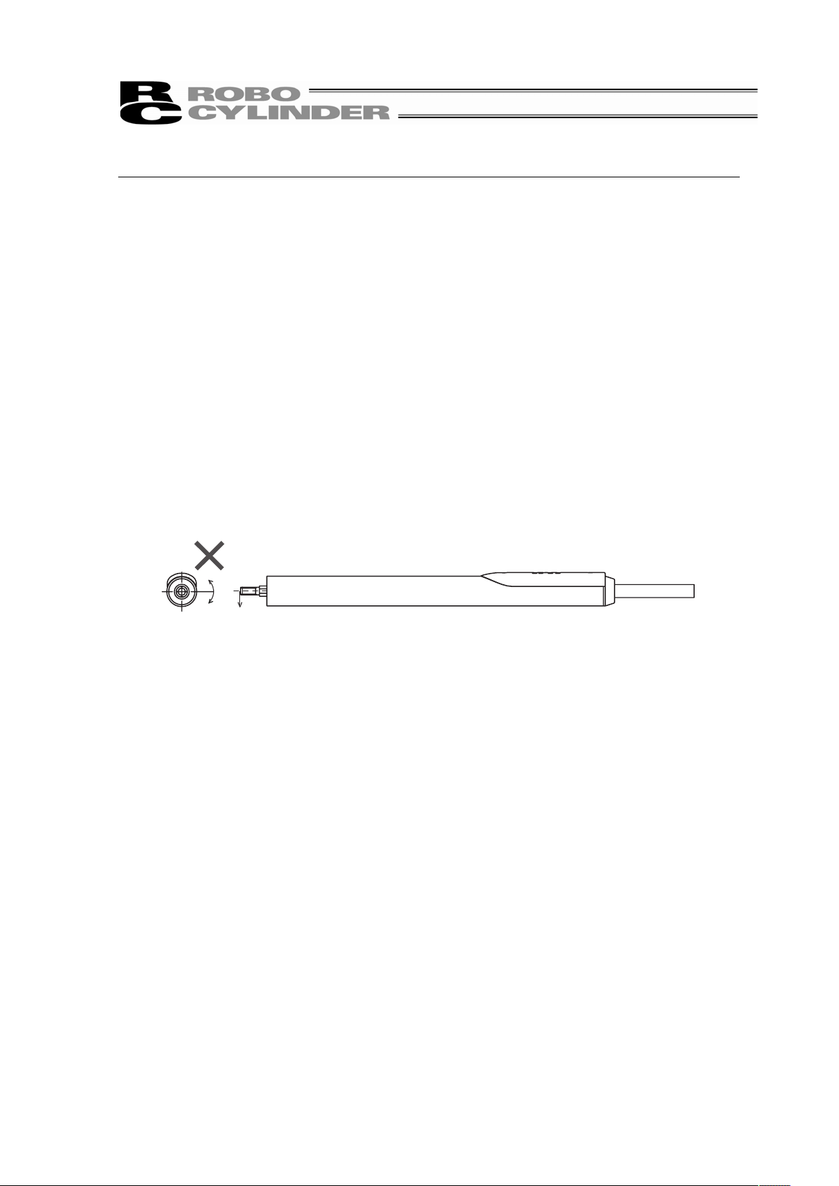
2.3.3 Attachment of Transported Objects
y Attach a transported item on the threaded area on the tip of the rod. Keep in mind of the
incomplete thread.
y When tightening, hold two faces with an open-end wrench so torque would not be applied on
the rod. Applying excessive torque to the rod may damage the components inside.
y The material of the rod is aluminum. Tighten the Enclosed nut with the Recommended
tightening torque described below. Excessive tightening torque may damage the threaded area.
W
A
B
M
φ
D
Width across flats
Dimensions for Attachment of Transported Objects
Type MScrew nominal
diameter
A
B
Effective thread
depth
ID
Rod diameter
W
Width across flats
RA1L M4 10 8 6 5.5
RA2L M5 12 10 8 7
RA3L M6 14 12 10 8
Enclosed Nut Recommended Tightening Torque
Type Enclosed nut Recommended tightening torque
RA1L M4 nut (class 1)
0.75N㨯m
RA2L M5 nut (class 1)
1.5N㨯m
RA3L M6 nut (class 1)
2.6N㨯m
Page 35

29
3. Connecting with the Controller
As the connection cable for the controller and the actuator, use the IAI dedicated controller and
dedicated connection cable.
This section, explains how to layout wires for a single axis.
x If the dedicated connection cable cannot be secured, reduce the load on the cable by allowing it
to deflect only by the weight of the cable or wire it in a self–standing cable hose, etc., having a
large radius.
x Do not cut and reconnect the dedicated connection cable for extension or shorten the cable.
x Do not pull on the dedicated connection cable or bend it forcibly.
x The actuator cable coming out of the motor unit is not meant to be bent. Fix the cable so it would
not be bent repeatedly.
Please consult with IAI if you require a different kind of cable than the one supplied.
[Connecting with the AMEC, ASEP and MSEP Controller]
Dedicated cables
x Motor • Encoder Integrated Cables CB-APSEP-MPAƑƑƑ
x Motor • Encoder Integrated Cables (
with brake cable) CB-APSEP-MPBAƑƑƑ
ƑƑƑ shows the cable length.
The max. length should be 10m.
Example) 080 = 8m
(Note) The simple absolute type is not applicable.
Dedicated Connection Cable
(connects controller and RCL)
Dedicated Controller
AMEC
ASEP
MSEP
r=68mm or more (Movable Use)
r=34mm or more (Fixed Use)
3. Connecting with the Controller
Page 36

3. Connecting with the Controller
30
[Connecting with the ACON and ASEL Controller]
Dedicated cables
xMotor • Encoder Integrated Cables CB-ACS-MPAƑƑƑ
xMotor • Encoder Integrated Cables (
with brake cable) CB-ACS-MPBAƑƑƑ
ƑƑƑ shows the cable length.
The max. length should be 10m.
Example) 080 = 8m
Dedicated Connection Cable
(connects controller and RCL)
Dedicated Controller
ACON
ASEL
r=84mm or more (Movable Use)
r=42mm or more (Fixed Use)
Page 37

31
3.1 Brake Box Installation for Brake-Equipped Type
Attach the brake box RCB-110-RCLB-0 for brake-equipped type.
3.1.1 Brake Box RCB-110-RCLB-0
Items Specifications
Power Voltage 24V DC±10%
Power Current MAX2.5A (Approx. 110ms at brake release)
Weight Approx. 35g
[Power / RDY Output Connector]
Applicable Cable : AWG24 to 16
Pin No. Signal name Contents
1 RDY+
2 RDY-
Ready contact
Open at brake overloaded alarm
3 +24V
4 0V
DC+24V Power Input
65
48
3
25
(1.8)
(1.8)
8.5
2.75
2-φ3.5
45
50.5
56
Brake Signal Output Connector
Connected to the controller
Power /
RDY Output Connector
LEDs display
•Green: RDY No alarm after power is on
•Red : ALM Brake overloaded alarm being generated
LEDs display
•Green:BK RLS
In brake release
•Yellow:RLS SIG
Output of the brake release signal
Brake Signal Output Connector
Connected to the Micro-cylinder
3. Connecting with the Controller
Page 38

3. Connecting with the Controller
32
3.1.2 Procedures to Connect and Start Brake Box
1) Shown below are examples for how to connect to the ACON Controller and the ASEP Controller.
(The procedures to connect it are the same as the ACON Controller for the AMEC, MSEP
Controllers, ASEP Controller and the ASEL Controller.)
Perform the connection following the examples below.
2) Connect +24V power supply and input to the brake box.
The current of 2.5A at maximum can flow for approximately 110ms at the brake release.
ACON
ASEP
Motor, Encoder cable
Brake cable
(CB-ACS-MPBA□□□)
Brake box
Micro-cylinder
(equipped with brake)
Micro-cylinder
(equipped with brake)
(RCB-110-RCLB-0)
Brake box
(RCB-110-RCLB-0)
Motor, Encoder cable
(CB-APSEP-MPBA□□□)
(CB-ACS-MPBA□□□)
Brake cable
(CB-ACS-MPBA□□□)
24V DC
power supply
24V DC
power supply
Examples for Connection
Page 39

33
Warning: For wiring, please follow the warnings stated below. When constructing a system as the
machinery equipment, pay attention to the wiring and connection of each cable so they are
conducted properly. Not following them may cause not only a malfunction such as cable
breakage or connection failure, or an operation error, but also electric shock or electric
leakage, or may even cause a fire.
• Use dedicated cables of IAI indicated in this Instruction manual. Contact us if you wish to have a
change to the specifications of the dedicated cables.
• Make sure to turn the power off in the process of power line or cable connection or disconnection.
• Do not attempt to cut a dedicated cable with connectors on both ends to extend, shorten or re-joint it.
• Hold the dedicated cable to avoid mechanical force being applied to the terminals and connectors.
• Use a cable pipe or duct to have an appropriate protection when there is a possibility of mechanical
damage on a dedicated cable.
• In case a dedicated cable is to be used at a moving part, make sure to lay out the cable without
applying any force to pull the connector or extreme bend on the cable. Do not attempt to use the
cable with a bending radius below the allowable value.
• Make certain that the connectors are plugged properly. Insufficient connection may cause an
operation error, thus it is extremely risky.
• Do not lay out the cables to where the machine runs over them.
• Pay attention to the cable layout so it would not hit peripherals during an operation. In case it does,
have an appropriate protection such as a cable track.
• When a cable is used hanging on the ceiling, prevent an environment that the cable swings with
acceleration or wind velocity.
• Make sure there is not too much friction inside the cable storage equipment.
• Do not apply radiated heat to power line or cables.
• Have a sufficient radius for bending, and avoid a bend concentrating on one point.
Steel Strap
(Piano Wire)
Tie them up softly.
• Do not let the cable bend, kink or twist.
3. Connecting with the Controller
Page 40

3. Connecting with the Controller
34
• Do not pull the cable with a strong force.
• Pay attention not to concentrate the twisting force to one point on a cable.
• Do not pinch, drop a heavy object onto or cut the cable.
• When a cable is fastened to affix, make sure to have an appropriate force and do not tighten too
much.
Do not use spiral tube in any
position where cables are bent
frequently.
Page 41

35
• PIO line, communication line, power and driving lines are to be put separately from each other and
do not tie them together. Arrange so that such lines are independently routed in the duct.
Follow the instructions below when using a cable track.
• If there is an indication to the cable for the space factor in a cable track, refer to the wiring instruction
given by the supplier when storing the cable in the cable track.
• Avoid the cables to get twined or twisted in the cable track, and also to have the cables move freely
and do not tie them up. (Avoid tension being applied when the cables are bent.)
Do not pile up cables. It may cause faster abrasion of the sheaths or cable breakage.
Power line
I/O lines (flat cable)
Duct
3. Connecting with the Controller
Page 42

4. Operational Conditions
36
4. Operational Conditions
4.1 Acceleration of the Setting
The acceleration is determined by the transported weight and the duty.
The graphs below show the upper limit for the acceleration against the transported weight
and the duty.
Set the acceleration to a value of Continuous Operation Available (100%) when the duty is
over 70% and up to 100%, and set it to a value of 70% when it is 70% or below.
Transportable Weight (horizontal) and Acceleration
Type RA1L RA2L RA3L
A
cceleration
[G]
Continuous
operation
available
When
controlling
at duty 70%
Continuous
operation
available
When
controlling
at duty 70%
Continuous
operation
available
When
controlling
at duty 70%
0.1
0.3
0.5 1 2
0.5 0.42
0.5
0.85
1
1.6
2
1.0 0.2 0.25 0.4 0.5 0.78 1
1.5 0.11 0.15 0.24 0.3 0.46 0.6
2.0 0.07 0.1 0.15 0.2 0.3 0.4
Operating time
Duty =
Operating time + Stop time
× 100
(Note) Have an external guide to receive any load so the rod would not get sideway load or
rotational load to be applied.
0.6
0.5
0.4
0.3
0.2
0.1
0
0
0.5
1 1.5 2
Weight [kg]
RA1L Transportable Weight (horizontal) and Acceleration
RA3L Transportable Weight (horizontal) and Acceleration
RA2L Transportable Weight (horizontal) and Acceleration
Duty 70%
Continuous
Operation
Available
Duty 70%
Continuous
Operation
Available
Duty 70%
Continuous
Operation
Available
Acceleration [G]
Weight [kg]
Acceleration [G]
Weight [kg]
Acceleration [G]
1.2
1
0.8
0.6
0.4
0.2
0
0 0.5 1 1.5 2
2.5
2
1.5
1
0.5
0
0 0.5
1
1.5 2
Page 43

37
4.2 Reference for Cycle Time
The graph below shows the cycle time in each acceleration pattern in maximum velocity.
Take this as a reference for the operation time.
Time [s]Time [s]Time [s]
Movement distance [mm]
Movement distance [mm]
Movement distance [mm]
RA1L Cycle Time
RA2L Cycle Time
RA3L Cycle Time
0 5 10 15 20 25
0.50
0.45
0.40
0.35
0.30
0.25
0.20
0.15
0.10
Setting speed : 300mm/sec
Installation posture : Horizontal
Setting speed : 340mm/sec
Installation posture : Horizontal
Setting speed : 450mm/sec
Installation posture : Horizontal
0.1G
0.3G
0.5G
1G
1.5G
2G
0.5kg
0.5kg
0.5kg
0.25kg
0.15kg
0.1kg
0 5 10 15
20
25
0.55
0.50
0.45
0.40
0.35
0.30
0.25
0.20
0.15
0.10
0.1G
0.3G
0.5G
1G
1.5G
2G
1kg
1kg
1kg
0.5kg
0.3kg
0.2kg
30
0
5 10
15 20 25
0.60
0.55
0.50
0.45
0.40
0.35
0.30
0.25
0.20
0.15
0.10
0.1G
0.3G
0.5G
1G
1.5G
2G
2kg
2kg
2kg
1kg
0.6kg
0.4kg
30 35 40
(Note) Have an external guide to receive any load so the rod would not get sideway load or
rotational load to be applied.
4. Operational Conditions
Page 44

4. Operational Conditions
38
4.3 Setting of Current Limiting Value at Pressing Operation
When having a pressing operation, set up the current limiting value which determines the pressing
force.
The graph below shows the current against the pressing force.
Take this as a reference for when making an adjustment to the pressing force.
There is no limit to the pressing duration. Continuous pressing can be performed.
Pressing Current Setting
30% 40%
50%
60% 70% 80%
Current Limiting Value [%]
10
9
8
7
6
5
4
3
2
1
0
Pressing force [N]
RA3L
RA2L
RA1L
* Under condition of horizontal orientation with no load or attached on the rod
Reference for Pressing Force unit : [N]
Current Limiting Value
Type
30% 40% 50% 60% 70% 80%
RA1L 0.75 1 1.25 1.5 1.75 2
RA2L 1.5 2 2.5 3 3.5 4
RA3L 3 4 5 6 7 8
Caution: • The pressing force is adjusted with the current limiting value, and the fluctuation of
pressing force gets big when the current limiting value is low. It is recommended to
use the product in the range from 60% to 80% if possible.
• There may be a difference in the pressing force due to the variation of each unit or a
difference in the pressing position.
• Setting from 71% to 80% for the current limiting value may not be performed for
some versions of the PC software and teaching pendant.
Velocity at Pressing
20mm/sec
Page 45

39
It is necessary to consider the influence of the weight of movable part as shown in the figures below
when installing in vertical orientation.
Horizontal VerticalDownward pressing VerticalUpward pressing
Weight of movable part m
Weight of movable part m
Weight of Movable Part unit : [N]
Type Weight of Movable Part
RA1L 0.5
RA2L 1
RA3L 1.8
Pressing force =
Thrust + Weight of Movable Part
F = f + m
Pressing force = Thrust
F = f
Pressing force =
Thrust – Weight of Movable Part
F =
f
–
m
4. Operational Conditions
Page 46

40
4.4 Vibration • Resonance Noise Control
There may be a case that vibration or resonance noise is generated as an impact of load weight,
operational condition, condition of installation or mechanical stiffness. In such a case, the vibration
or resonance noise can be controlled by increasing the torque filter time constant (parameter)
shown below.
Note that increasing this value to much may sacrifice the stableness of controllability.
For how to set or change the parameter, refer to the instruction manual of the PC software or
teaching pendant that is applied to the controller.
Caution: Do not attempt to change the parameters except for the torque filter time constant
since they are already in the optimum setting for the actuator specifications.
ACON • RACON Controller
Parameter No. Name Default value Setting
33 Torque filter time constant 0 25 or 50
ASEL Controller
Parameter No. Name Default value Setting
45 Torque filter time constant 0 25 or 50
4. Operational Conditions
Page 47

41
5. Maintenance Inspection
5.1 Inspection Items and Schedule
Follow the maintenance inspection schedule below.
It is assumed that the equipment is operating 8 hours per day.
If the equipment is running continuously night and day or otherwise running at a high operating rate,
inspect more often as needed.
External visual inspection
Start of operation
{
After 1 month of operation
{
After 3 months of operation
{
Every 3 months thereafter
{
After 3 years of operation, or upon reaching 5,000
km in traveled distance
{
Every year thereafter
{
5.2 External Visual Inspection
An external visual inspection should check the following things.
Main unit
Loose actuator mounting bolts, other loose items
Visual inspection on rod sliding area (should be no foreign
object to be put on)
Smooth movement of rod when moving it manually by hand
Cables Scratches, proper connections
Overall Irregular noise, vibration
5.3 Cleaning
Ɣ Clean exterior surfaces as necessary.
Ɣ Use a soft cloth to wipe away dirt and buildup.
Ɣ Do not blow too hard with compressed air as it may cause dust to get in through the gaps.
Ɣ Do not use oil–based solvents as they can harm lacquered and painted surfaces.
Ɣ To remove severe buildup, wipe gently with a soft cloth soaked in a neutral detergent or alcohol.
5. Maintenance Inspection
Page 48

6. External Dimensions
42
6. External Dimensions
6.1 RCL-RA1L without brake type
10 4
5.5
(Width across flats)
Stroke
25
M4 × 0.7
(
Effective Thread Depth 8)
SE
14
186
Home
1 1
ME
ME
(
114.5)
φ
16
-0.1
0
φ 6
(Rod diameter)
200
8.1
3.2
7
ME
SE : Stroke End
: Mechanical end
Enclosed nut
M4×0.7 (Class 1)
(
18
)
(
φ7
)
6.2 RCL-RA1L equipped with brake (option)
M4
5.5
(27.6)
(16)
8.1
3.2
7
φ
1
6
-0.1
0
φ
6
ME
ME
SE
1
1
Stroke
25
14 38 186
238
(114.5)
(
300)
(
630)
34
10
4
(Width across flats)
(
Effective Thread Depth 8
)
Enclosed nut
M4 (Class 1)
Home
(Rod diameter)
(
18
)
(
13.3
)
(
16
)
(
φ7
)
(
φ5.1
)
ME
SE : Stroke End
: Mechanical end
Weight : 0.2 [kg]
Weight : 0.25 [kg]
Page 49

43
6.3 RCL-RA2L without brake type
φ
8
φ
0
-0.1
1 1
ME
SE
ME
17
Stroke
30
236
219
M5 × 0.8
7
12 5
20
9.2 4
8
(Width across flats)
(
Effective Thread Depth 8
)
(
140
)
Enclosed nut
M5×0.8 (Class 1)
Home
(Rod diameter)
(
22
)
(
φ7
)
ME
SE : Stroke End
: Mechanical end
6.4 RCL-RA2L equipped with brake (option)
M5
7
(27.6)
(22)
(300)
(630)
(16)
9.2
4
8
12
5
0
-0.1
1 1
ME
SE
Stroke
30
ME
17 43 219
279
39
φ
8
φ
20
(Width across flats)
(
Effective Thread Depth 8
)
Enclosed nut
M5 (Class 1)
Home
(Rod diameter)
140
(
φ7
)
(
φ5.1
)
(
φ13.3
)
(
16
)
ME
SE : Stroke End
: Mechanical end
Weight : 0.33 [kg]
Weight : 0.4 [kg]
6. External Dimensions
Page 50

44
6.5 RCL-RA3L without brake type
0
-0.1
1 1
ME
SE
Storke
40
20
280
300
M6
8
14 6
ME
Home
11.5
5
10
φ
10
φ
25
(Width across flats)
(
Effective Thread Depth 8
)
Enclosed nut
M6 (Class 1)
(Rod diameter)
(
φ7
)
(
27
)
(
188
)
ME
SE : Stroke End
: Mechanical end
6.6 RCL-RA3L equipped with brake (option)
M6
8
(27.6)
(16)
11.5
5
10
14
6
φ
10
φ
25
0
-0.1
Home
ME
SE
ME
1 1
Stroke
40
20 54
50
280
354
(Width across flats)
(
Effective Thread Depth 8
)
Enclosed nut
M6 (Class 1)
(Rod diameter)
(
φ7
)
(
φ5.1
)
(
27
)
(
16
)
(
13.3
)
(
188
)
(
630
)
(
300
)
ME
SE : Stroke End
: Mechanical end
Weight : 0.6 [kg]
Weight : 0.77 [kg]
6. External Dimensions
Page 51

45
7. Life
The product life is assumed to be 10,000km (reference) under the condition that it runs with
maximum load capacity and maximum acceleration/deceleration.
7. Life
Page 52

8. Warranty
46
8 Warranty
8.1 Warranty Period
One of the following periods, whichever is shorter:
• 18 months after shipment from our factory
• 12 months after delivery to a specified location
• 2,500 operational hours
8.2 Scope of the Warranty
Our products are covered by warranty when all of the following conditions are met. Faulty
products covered by warranty will be replaced or repaired free of charge:
(1) The breakdown or problem in question pertains to our product as delivered by us or our
authorized dealer.
(2) The breakdown or problem in question occurred during the warranty period.
(3) The breakdown or problem in question occurred while the product was in use for an
appropriate purpose under the conditions and environment of use specified in the operation
manual and catalog.
(4) The breakdown or problem in question was caused by a specification defect or problem, or
by the poor quality of our product.
Note that breakdowns due to any of the following reasons are excluded from the scope of
warranty:
[1] Anything other than our product
[2] Modification or repair performed by a party other than us (unless we have approved
such modification or repair)
[3] Anything that could not be easily predicted with the level of science and technology
available at the time of shipment from our company
[4] A natural disaster, man-made disaster, incident or accident for which we are not liable
[5] Natural fading of paint or other symptoms of aging
[6] Wear, depletion or other expected result of use
[7] Operation noise, vibration or other subjective sensation not affecting function or
maintenance
Note that the warranty only covers our product as delivered and that any secondary loss arising
from a breakdown of our product is excluded from the scope of warranty.
8.3 Honoring the Warranty
As a rule, the product must be brought to us for repair under warranty.
8.4 Limited Liability
(1) We shall assume no liability for any special damage, consequential loss or passive loss
such as a loss of expected profit arising from or in connection with our product.
(2) We shall not be liable for any program or control method created by the customer to operate
our product or for the result of such program or control method.
Page 53

47
8.5 Conditions of Conformance with Applicable Standards/Regulations, Etc., and Applications
(1) If our product is combined with another product or any system, device, etc., used by the
customer, the customer must first check the applicable standards, regulations and/or rules.
The customer is also responsible for confirming that such combination with our product
conforms to the applicable standards, etc. In such a case we will not be liable for the
conformance of our product with the applicable standards, etc.
(2) Our product is for general industrial use. It is not intended or designed for the applications
specified below, which require a high level of safety. Accordingly, as a rule our product
cannot be used in these applications. Contact us if you must use our product for any of
these applications:
[1] Medical equipment pertaining to maintenance or management of human life or health
[2] A mechanism or mechanical equipment intended to move or transport people (such
as a vehicle, railway facility or aviation facility)
[3] Important safety parts of mechanical equipment (such as safety devices)
[4] Equipment used to handle cultural assets, art or other irreplaceable items
(3) Contact us at the earliest opportunity if our product is to be used in any condition or
environment that differs from what is specified in the catalog or operation manual.
8.6 Other Items Excluded from Warranty
The price of the product delivered to you does not include expenses associated with
programming, the dispatch of engineers, etc. Accordingly, a separate fee will be charged in the
following cases even during the warranty period:
[1] Guidance for installation/adjustment and witnessing of test operation
[2] Maintenance and inspection
[3] Technical guidance and education on operating/wiring methods, etc.
[4] Technical guidance and education on programming and other items related to programs
8. Warranty
Page 54

48
Change History
Revision Date Revision Description
October 2009
March 2013
First edition
Second edition
• RCL-RA1L Brake-equipped Type, RCL-RA2L Brake-equipped Type
and RCL-RA3L Brake-equipped Type are added
Third edition
• Revised overall
Change History
Page 55

Page 56

Manual No.: ME0192-3A (March 2013)
The information contained in this document is subject to change without notice for purposes of
product improvement.
Copyright © 2013. Mar. IAI Corporation. All rights reserved.
13.03.000
Head Office: 577-1 Obane Shimizu-KU Shizuoka City Shizuoka 424-0103, Japan
TEL +81-54-364-5105 FAX +81-54-364-2589
website: www.iai-robot.co.jp/
Ober der Röth 4, D-65824 Schwalbach am Taunus, Germany
TEL 06196-88950 FAX 06196-889524
SHANGHAI JIAHUA BUSINESS CENTER A8-303, 808, Hongqiao Rd. Shanghai 200030, China
TEL 021-6448-4753 FAX 021-6448-3992
website: www.iai-robot.com
Technical Support available in USA, Europe and China
Head Office: 2690 W. 237th Street, Torrance, CA 90505
TEL (310) 891-6015 FAX (310) 891-0815
Chicago Office: 1261 Hamilton Parkway, Itasca, IL 60143
TEL (630) 467-9900 FAX (630) 467-9912
TEL (678) 354-9470 FAX (678) 354-9471
website: www.intelligentactuator.com
Atlanta Office: 1220 Kennestone Circle, Suite 108, Marietta, GA 30066
 Loading...