

Page 1

ROBO Cylinder
Rod Type
RCA Actuators
RCAW Actuators, Dustproof/Splash-proof Type
Operating Manual
Eighth Edition
䎰䏒䏗䏒䏕䎃䎶䏗䏕䏄䏌䏊䏋䏗䎃䎷䏜䏓䏈䎃䎋䎦䏒䏘䏓䏏䏌䏑䏊䎃䎷䏜䏓䏈䎌䎃
䎵䎤䎖䎦䎏䎵䎪䎶䎖䎦䎏䎵䎪䎧䎖䎦䎏䎵䎤䎗䎦䎏䎵䎪䎶䎗䎦䎏䎵䎪䎧䎗䎦䎃
䎰䏒䏗䏒䏕䎃䎶䏗䏕䏄䏌䏊䏋䏗䎃䎷䏜䏓䏈䎃䎋䎥䏘䏌䏏䏗䎐䏌䏑䎃䎷䏜䏓䏈䎌䎃
䎵䎤䎖䎧䎏䎵䎪䎶䎖䎧䎏䎵䎪䎧䎖䎧䎏䎵䎤䎗䎧䎏䎵䎪䎶䎗䎧䎏䎵䎪䎧䎗䎧䎃
䎰䏒䏗䏒䏕䎃䎵䏈䏙䏈䏕䏖䏌䏑䏊䎃䎷䏜䏓䏈䎃
䎵䎤䎖䎵䎏䎵䎪䎧䎖䎵䎏䎵䎤䎗䎵䎏䎵䎪䎧䎗䎵䎃
䎃
䎰䏒䏗䏒䏕䎃䎶䏗䏕䏄䏌䏊䏋䏗䎃䎷䏜䏓䏈䎃䎋䎦䏒䏘䏓䏏䏌䏑䏊䎃䎷䏜䏓䏈䎌䎃
䎵䎤䎖䎦䎏䎵䎤䎗䎦䎃
䎰䏒䏗䏒䏕䎃䎶䏗䏕䏄䏌䏊䏋䏗䎃䎷䏜䏓䏈䎃䎋䎥䏘䏌䏏䏗䎐䏌䏑䎃䎷䏜䏓䏈䎌䎃
䎵䎤䎖䎧䎏䎵䎤䎗䎧䎃
䎰䏒䏗䏒䏕䎃䎵䏈䏙䏈䏕䏖䏌䏑䏊䎃䎷䏜䏓䏈䎃
䎵䎤䎖䎵䎏䎵䎤䎗䎵䎃
IAI America, Inc.
Page 2

Page 3

Please Read Before Use
Thank you for purchasing our product.
This Operation Manual explains the handling methods, structure and maintenance of this product,
among others, providing the information you need to know to use the product safely.
Before using the product, be sure to read this manual and fully understand the contents explained herein
to ensure safe use of the product.
The CD or DVD that comes with the product contains Operation Manuals for IAI products.
When using the product, refer to the necessary portions of the applicable Operation manual by printing
them out or displaying them on a PC.
After reading the Operation Manual, keep it in a convenient place so that whoever is handling this
product can reference it quickly when necessary.
[Important]
x This Operation Manual is original.
x The product cannot be operated in any way unless expressly specified in this Operation Manual. IAI
shall assume no responsibility for the outcome of any operation not specified herein.
x Information contained in this Operation Manual is subject to change without notice for the purpose
of product improvement.
x If you have any question or comment regarding the content of this manual, please contact the IAI
sales office near you.
x Using or copying all or part of this Operation Manual without permission is prohibited.
x The company names, names of products and trademarks of each company shown in the sentences
are registered trademarks.
Page 4

Page 5

Table of Contents
Safety Guide ························································································································1
Precautions·························································································································· 8
International Standards Compliances ·················································································· 9
Names of the Parts ············································································································10
1. Specifications Check··································································································· 13
1.1 Checking the Product ·····································································································13
1.1.1 Parts ··································································································································13
1.1.2 Instruction Manuals related to this product, which are contained in the CD/DVD.···········14
1.1.3 How to Read the Model Nameplate··················································································14
1.1.4 How to Read the Model Number·······················································································15
1.2 Specification····················································································································16
1.2.1 Speed································································································································16
1.2.2 Maximum Acceleration and Transportable Weight ···························································17
1.2.3 Driving System • Position Detector ···················································································19
1.2.4 Positioning Precision·········································································································20
1.2.5 Rod Non-Rotation Accuracy······························································································20
1.2.6 Allowable Running Torque ································································································22
1.2.7 Relation of Allowable Tip Load and Running Life ·····························································22
1.2.8 Radial load and Tip Flexure ······························································································23
1.2.9 Duty Ratio in Continuous Operation ·················································································24
1.2.10 Protection class·················································································································25
1.3 Options ···························································································································26
1.3.1 Brake Type························································································································26
1.3.2 High Acceleration/Deceleration Type················································································26
1.3.3 Home-Position Check Sensor···························································································26
1.3.4 Power Saving Type ···········································································································26
1.3.5 Motor Left Reversed, Motor Right Reversed (Model No. : ML, MR)·································26
1.3.6 Guide Attachment Directions (Only for Single guide type) ···············································26
1.3.7 Front Flange (Model No. : FL)···························································································27
1.3.8 Rear Flange (Model No. : FLR)·························································································28
1.3.9 Foot (Model No. : FT)········································································································30
1.3.10 Foot (Attached on the Right Side/Left Side) ·····································································32
1.3.11 Knuckle Joint (Model No. : NJ) ·························································································33
1.3.12 Clevis (Model No. : QR)····································································································34
1.3.13 Rear Attachment Plate (Model No. : RP) ··········································································35
1.3.14 Front Trunnion (Model No. : TRF)·····················································································36
1.3.15 Rear Trunnion (Model No. : TRR)·····················································································37
1.4 Motor • Encoder Cables··································································································38
1.4.1 Motor cable ·······················································································································38
1.4.2 Encoder cable/robot encoder cable
CB-ACS-PAƑƑƑ/CB-ACS-PA-ƑƑƑ-RB··············································································38
1.4.3 Motor/Encoder Integrated Cable for AMEC/ASEP····························································39
2. Installation···················································································································40
2.1 Transportation·················································································································40
2.2 Installation and Storage • Preservation Environment······················································42
2.3 How to Installation···········································································································43
2.3.1 General Rules on Installation····························································································43
2.3.2 Installation ·························································································································44
2.3.3 Connecting the Air Tube of the RCAW Dustproof/Splash-proof Type·······························54
Page 6

3. Connecting with Controller ··························································································55
4. Maintenance ··············································································································· 59
4.1 Maintenance Schedule ···································································································59
4.2 Visual Inspection of the Machine ····················································································59
4.3 Cleaning··························································································································59
4.4 Applying Grease to the Sliding Surface of the Rod ························································60
4.5 Reduction Belt [Motor Reversing Type] ··········································································61
4.5.1 Inspecting the Belt ············································································································61
4.5.2 Applicable Belt ··················································································································61
4.5.3 Adjusting the Belt Tension·································································································62
4.5.4 Replacing the Belt of the Motor Reversing Type: RA3R/RA4R Types ·····························63
4.6 Replacing the Motor········································································································68
4.6.1 Replacing the Motor of the Motor Straight Type (Coupling Type):
RA3C/RA4C Types ···········································································································68
4.6.2 Replacing the Motor of the Motor Reversing Type: RA3R/RA4R Types ··························75
4.7 Replacing the Bellows of the RCAW Dustproof/Splash-proof Type ································81
5. Appendix ·····················································································································84
5.1 RCA-RA3C ·····················································································································84
5.2 RCA-RA4C ·····················································································································85
5.3 RCA-RA3D ·····················································································································86
5.4 RCA-RA4D ·····················································································································87
5.5 RCA-RA3R ·····················································································································88
5.6 RCA-RA4R ·····················································································································89
5.7 RCA-RGS3C···················································································································90
5.8 RCA-RGS4C···················································································································91
5.9 RCA-RGS3D···················································································································92
5.10 RCA-RGS4D ·················································································································93
5.11 RCA-RGD3C··················································································································94
5.12 RCA-RGD4C ·················································································································95
5.13 RCA-RGD3D ·················································································································96
5.14 RCA-RGD4D ·················································································································97
5.15 RCA-RGD3R ·················································································································98
5.16 RCA-RGD4R ·················································································································99
5.17 RCAW-RA3C/RA3D/RA3R··························································································100
5.18 RCAW-RA4C/RA4D/RA4R··························································································101
6. Life ····························································································································102
7. Warranty ··················································································································· 103
7.1 Warranty Period············································································································103
7.2 Scope of the Warranty ··································································································103
7.3 Honoring the Warranty··································································································103
7.4 Limited Liability ·············································································································104
7.5 Conditions of Conformance with Applicable Standards/Regulations, Etc.,
and Applications············································································································104
7.6 Other Items Excluded from Warranty············································································104
Change History ················································································································105
Page 7

1
Safety Guide
“Safety Guide” has been written to use the machine safely and so prevent personal injury or property damage
beforehand. Make sure to read it before the operation of this product.
Safety Precautions for Our Products
The common safety precautions for the use of any of our robots in each operation.
No.
Operation
Description
Description
1 Model Selection Ɣ This product has not been planned and designed for the application where high
level of safety is required, so the guarantee of the protection of human life is
impossible. Accordingly, do not use it in any of the following applications.
1) Medical equipment used to maintain, control or otherwise affect human life
or physical health.
2) Mechanisms and machinery designed for the purpose of moving or
transporting people (For vehicle, railway facility or air navigation facility)
3) Important safety parts of machinery (Safety device, etc.)
Ɣ Do not use the product outside the specifications. Failure to do so may
considerably shorten the life of the product.
Ɣ Do not use it in any of the following environments.
1) Location where there is any inflammable gas, inflammable object or
explosive
2) Place with potential exposure to radiation
3) Location with the ambient temperature or relative humidity exceeding the
specification range
4) Location where radiant heat is added from direct sunlight or other large heat
source
5) Location where condensation occurs due to abrupt temperature changes
6) Location where there is any corrosive gas (sulfuric acid or hydrochloric acid)
7) Location exposed to significant amount of dust, salt or iron powder
8) Location subject to direct vibration or impact
Ɣ For an actuator used in vertical orientation, select a model which is equipped
with a brake. If selecting a model with no brake, the moving part may drop
when the power is turned OFF and may cause an accident such as an injury or
damage on the work piece.
Page 8

2
No.
Operation
Description
Description
2 Transportation Ɣ When carrying a heavy object, do the work with two or more persons or utilize
equipment such as crane.
Ɣ When the work is carried out with 2 or more persons, make it clear who is to be
the leader and who to be the follower(s) and communicate well with each other
to ensure the safety of the workers.
Ɣ When in transportation, consider well about the positions to hold, weight and
weight balance and pay special attention to the carried object so it would not
get hit or dropped.
Ɣ Transport it using an appropriate transportation measure.
The actuators available for transportation with a crane have eyebolts attached
or there are tapped holes to attach bolts. Follow the instructions in the
Operating manual for each model.
Ɣ Do not step or sit on the package.
Ɣ Do not put any heavy thing that can deform the package, on it.
Ɣ When using a crane capable of 1t or more of weight, have an operator who has
qualifications for crane operation and sling work.
Ɣ When using a crane or equivalent equipments, make sure not to hang a load
that weighs more than the equipment’s capability limit.
Ɣ Use a hook that is suitable for the load. Consider the safety factor of the hook
in such factors as shear strength.
Ɣ Do not get on the load that is hung on a crane.
Ɣ Do not leave a load hung up with a crane.
Ɣ Do not stand under the load that is hung up with a crane.
3 Storage and
Preservation
Ɣ The storage and preservation environment conforms to the installation
environment. However, especially give consideration to the prevention of
condensation.
Ɣ Store the products with a consideration not to fall them over or drop due to an
act of God such as earthquake.
4 Installation and
Start
(1) Installation of Robot Main Body and Controller, etc.
Ɣ Make sure to securely hold and fix the product (including the work part). A fall,
drop or abnormal motion of the product may cause a damage or injury.
Also, be equipped for a fall-over or drop due to an act of God such as
earthquake.
Ɣ Do not get on or put anything on the product. Failure to do so may cause an
accidental fall, injury or damage to the product due to a drop of anything,
malfunction of the product, performance degradation, or shortening of its life.
Ɣ When using the product in any of the places specified below, provide a
sufficient shield.
1) Location where electric noise is generated
2) Location where high electrical or magnetic field is present
3) Location with the mains or power lines passing nearby
4) Location where the product may come in contact with water, oil or chemical
droplets
Page 9

3
No.
Operation
Description
Description
(2) Cable Wiring
Ɣ Use our company’s genuine cables for connecting between the actuator and
controller, and for the teaching tool.
Ɣ Do not scratch on the cable. Do not bend it forcibly. Do not pull it. Do not coil it
around. Do not insert it. Do not put any heavy thing on it. Failure to do so may
cause a fire, electric shock or malfunction due to leakage or continuity error.
Ɣ Perform the wiring for the product, after turning OFF the power to the unit, so
that there is no wiring error.
Ɣ When the direct current power (+24V) is connected, take the great care of the
directions of positive and negative poles. If the connection direction is not
correct, it might cause a fire, product breakdown or malfunction.
Ɣ Connect the cable connector securely so that there is no disconnection or
looseness. Failure to do so may cause a fire, electric shock or malfunction of
the product.
Ɣ Never cut and/or reconnect the cables supplied with the product for the
purpose of extending or shortening the cable length. Failure to do so may
cause the product to malfunction or cause fire.
4 Installation and
Start
(3) Grounding
Ɣ The grounding operation should be performed to prevent an electric shock or
electrostatic charge, enhance the noise-resistance ability and control the
unnecessary electromagnetic radiation.
Ɣ For the ground terminal on the AC power cable of the controller and the
grounding plate in the control panel, make sure to use a twisted pair cable with
wire thickness 0.5mm
2
(AWG20 or equivalent) or more for grounding work. For
security grounding, it is necessary to select an appropriate wire thickness
suitable for the load. Perform wiring that satisfies the specifications (electrical
equipment technical standards).
Ɣ Perform Class D Grounding (former Class 3 Grounding with ground resistance
100: or below).
Page 10

4
No.
Operation
Description
Description
4 Installation and
Start
(4) Safety Measures
Ɣ When the work is carried out with 2 or more persons, make it clear who is to be
the leader and who to be the follower(s) and communicate well with each other
to ensure the safety of the workers.
Ɣ When the product is under operation or in the ready mode, take the safety
measures (such as the installation of safety and protection fence) so that
nobody can enter the area within the robot’s movable range. When the robot
under operation is touched, it may result in death or serious injury.
Ɣ Make sure to install the emergency stop circuit so that the unit can be stopped
immediately in an emergency during the unit operation.
Ɣ Take the safety measure not to start up the unit only with the power turning ON.
Failure to do so may start up the machine suddenly and cause an injury or
damage to the product.
Ɣ Take the safety measure not to start up the machine only with the emergency
stop cancellation or recovery after the power failure. Failure to do so may result
in an electric shock or injury due to unexpected power input.
Ɣ When the installation or adjustment operation is to be performed, give clear
warnings such as “Under Operation; Do not turn ON the power!” etc. Sudden
power input may cause an electric shock or injury.
Ɣ Take the measure so that the work part is not dropped in power failure or
emergency stop.
Ɣ Wear protection gloves, goggle or safety shoes, as necessary, to secure safety.
Ɣ Do not insert a finger or object in the openings in the product. Failure to do so
may cause an injury, electric shock, damage to the product or fire.
Ɣ When releasing the brake on a vertically oriented actuator, exercise precaution
not to pinch your hand or damage the work parts with the actuator dropped by
gravity.
5 Teaching Ɣ When the work is carried out with 2 or more persons, make it clear who is to be
the leader and who to be the follower(s) and communicate well with each other
to ensure the safety of the workers.
Ɣ Perform the teaching operation from outside the safety protection fence, if
possible. In the case that the operation is to be performed unavoidably inside
the safety protection fence, prepare the “Stipulations for the Operation” and
make sure that all the workers acknowledge and understand them well.
Ɣ When the operation is to be performed inside the safety protection fence, the
worker should have an emergency stop switch at hand with him so that the unit
can be stopped any time in an emergency.
Ɣ When the operation is to be performed inside the safety protection fence, in
addition to the workers, arrange a watchman so that the machine can be
stopped any time in an emergency. Also, keep watch on the operation so that
any third person can not operate the switches carelessly.
Ɣ Place a sign “Under Operation” at the position easy to see.
Ɣ When releasing the brake on a vertically oriented actuator, exercise precaution
not to pinch your hand or damage the work parts with the actuator dropped by
gravity.
* Safety protection Fence : In the case that there is no safety protection fence,
the movable range should be indicated.
Page 11

5
No.
Operation
Description
Description
6 Trial Operation Ɣ When the work is carried out with 2 or more persons, make it clear who is to be
the leader and who to be the follower(s) and communicate well with each other
to ensure the safety of the workers.
Ɣ After the teaching or programming operation, perform the check operation one
step by one step and then shift to the automatic operation.
Ɣ When the check operation is to be performed inside the safety protection
fence, perform the check operation using the previously specified work
procedure like the teaching operation.
Ɣ Make sure to perform the programmed operation check at the safety speed.
Failure to do so may result in an accident due to unexpected motion caused by
a program error, etc.
Ɣ Do not touch the terminal block or any of the various setting switches in the
power ON mode. Failure to do so may result in an electric shock or
malfunction.
7 Automatic
Operation
Ɣ Check before starting the automatic operation or rebooting after operation stop
that there is nobody in the safety protection fence.
Ɣ Before starting automatic operation, make sure that all peripheral equipment is
in an automatic-operation-ready state and there is no alarm indication.
Ɣ Make sure to operate automatic operation start from outside of the safety
protection fence.
Ɣ In the case that there is any abnormal heating, smoke, offensive smell, or
abnormal noise in the product, immediately stop the machine and turn OFF the
power switch. Failure to do so may result in a fire or damage to the product.
Ɣ When a power failure occurs, turn OFF the power switch. Failure to do so may
cause an injury or damage to the product, due to a sudden motion of the
product in the recovery operation from the power failure.
Page 12

6
No.
Operation
Description
Description
8 Maintenance
and Inspection
Ɣ When the work is carried out with 2 or more persons, make it clear who is to be
the leader and who to be the follower(s) and communicate well with each other
to ensure the safety of the workers.
Ɣ Perform the work out of the safety protection fence, if possible. In the case that
the operation is to be performed unavoidably inside the safety protection fence,
prepare the “Stipulations for the Operation” and make sure that all the workers
acknowledge and understand them well.
Ɣ When the work is to be performed inside the safety protection fence, basically
turn OFF the power switch.
Ɣ When the operation is to be performed inside the safety protection fence, the
worker should have an emergency stop switch at hand with him so that the unit
can be stopped any time in an emergency.
Ɣ When the operation is to be performed inside the safety protection fence, in
addition to the workers, arrange a watchman so that the machine can be
stopped any time in an emergency. Also, keep watch on the operation so that
any third person can not operate the switches carelessly.
Ɣ Place a sign “Under Operation” at the position easy to see.
Ɣ For the grease for the guide or ball screw, use appropriate grease according to
the Operating manual for each model.
Ɣ Do not perform the dielectric strength test. Failure to do so may result in a
damage to the product.
Ɣ When releasing the brake on a vertically oriented actuator, exercise precaution
not to pinch your hand or damage the work parts with the actuator dropped by
gravity.
Ɣ The slider or rod may get misaligned OFF the stop position if the servo is
turned OFF. Be careful not to get injured or damaged due to an unnecessary
operation.
Ɣ Pay attention not to lose the cover or untightened screws, and make sure to
put the product back to the original condition after maintenance and inspection
works.
Use in incomplete condition may cause damage to the product or an injury.
* Safety protection Fence : In the case that there is no safety protection fence,
the movable range should be indicated.
9 Modification and
Dismantle
Ɣ Do not modify, disassemble, assemble or use of maintenance parts not
specified based at your own discretion.
10 Disposal Ɣ When the product becomes no longer usable or necessary, dispose of it
properly as an industrial waste.
Ɣ When removing the actuator for disposal, pay attention to drop of components
when detaching screws.
Ɣ Do not put the product in a fire when disposing of it.
The product may burst or generate toxic gases.
11 Other Ɣ Do not come close to the product or the harnesses if you are a person who
requires a support of medical devices such as a pacemaker. Doing so may
affect the performance of your medical device.
Ɣ See Overseas Specifications Compliance Manual to check whether complies if
necessary.
Ɣ For the handling of actuators and controllers, follow the dedicated Operating
manual of each unit to ensure the safety.
Page 13

7
Alert Indication
The safety precautions are divided into “Danger”, “Warning”, “Caution” and “Notice” according to the warning
level, as follows, and described in the Operating manual for each model.
Level Degree of Danger and Damage Symbol
Danger
This indicates an imminently hazardous situation which, if the product is
not handled correctly, will result in death or serious injury.
Danger
Warning
This indicates a potentially hazardous situation which, if the product is
not handled correctly, could result in death or serious injury.
Warning
Caution
This indicates a potentially hazardous situation which, if the product is
not handled correctly, may result in minor injury or property damage.
Caution
Notice
This indicates lower possibility for the injury, but should be kept to use
this product properly.
Notice
Page 14

8
Precautions
1. Ensure use of the product in the specified conditions, environments and ranges.
Operation out of the specified conditions could cause a drop in performance or malfunction of the product.
2. Set the allowable load of the move on rod tip within the allowable range.
An operation with the load beyond the allowable load of the move on rod tip may cause an abnormal noise,
vibration, malfunction or shortened life. If it is extreme, flaking may occur on the guide.
3. If back and forth operations are performed repeatedly in short distance, it may wear out
the film of grease.
Continuous back and forth operation within a distance less than 30mm may cause wear of grease.
As a reference, have approximately 5 cycles of back and forth operation in a distance more than 50mm in
every 5,000 to 10,000 cycles to regenerate the oil film. Keep using the actuator with the grease worn out
may cause malfunction. If it is extreme, flaking may occur on the guide.
4. Do not apply any rotation torque on the rod.
Doing so may damage the internal component such as the rod stopper, and may result in an operation
failure.
Page 15

9
International Standards Compliances
This actuator complies with the following overseas standard.
Refer to Overseas Standard Compliance Manual (ME0287) for more detailed information.
RoHS CE Marking
{ {
Page 16

10
Names of the Parts
In this Operation Manual, the left and right sides are indicated by looking at the actuator from the motor end,
with the actuator placed horizontally, as shown in the figure below.
[RA3C, RA4C]
[RA3D, RA4D]
[RA3R, RA4R]
Rod Cover
Motor Unit
Head Cover
Cylinder Tube
Right
Left
Motor SideRod Side
Rod
Rod-Tip Adapter
Cable
Brake Unit
Head Cover
Cylinder Tube
Right
Left
Motor Side
Rod Side
Rod Cover
Motor Unit
Cable
Rod-Tip Adapter
Rod
Right
Left
Motor SideRod Side
Brake Unit
Cable
Pulley Case
Head Cover
Cylinder Tube
Rod Cover
Rod
Rod-Tip Adapter
Brake Unit
Page 17

11
[RGS3C, RGS3D, RGS4C, RGS4D]
RGS3D and RGS4C are non-brake-equipped types.
[RGD3C, RGD3D, RGD4C, RGD4D]
RGD3D and RGD4C are non-brake-equipped types.
[RGD3R, RGD4R]
Right
Left
Motor SideRod Side
Guide Bearing
Guide Rod
Head Cover
Motor Unit
Cable
Cylinder Tube
Rod Cover
Rod
Guide Bracket
Brake Unit
Right
Left
Guide Bracket
Guide Bearing
Guide Rod
Head Cover
Motor Unit
Motor Side
Rod Side
Rod
Rod Cover
Cylinder Tube
Cable
Brake Unit
Right
Left
Guide Bearing
Guide Bracket
Guide Rod
Head Cover
Motor Unit
Rod Cover
Rod
Cable
Motor Side
Rod Side
Brake Unit
Page 18

12
Dust and Splash-Proof Type
[RA3C, RA3D, RA4C, RA4D]
RA3D and RA4D are non-brake-equipped types.
[RA3R, RA4R]
Bellows
Right
Left
Motor SideRod Side
Suction/Exhaust Port
Cylinder Tube
Head Cover
Motor Unit
Cable
Rod Cover
Rod
Rod-Tip Adapter
Brake Unit
Bellows
Right
Left
Suction/Exhaust Port
Cable
Motor Unit
Rod
Rod-Tip Adapter
Cylinder Tube
Rod Cover
Pulley Case
Head Cover
Motor Side
Rod Side
Brake Unit
Page 19

13
1. Specifications Check
1.1 Checking the Product
The standard configuration of this product is comprised of the following parts.
Caution: Check for the enclosed components referring to the component list. If you find any fault or
missing part, contact your local IAI distributor or our company.
1.1.1 Parts
No. Part Name Model Quantity Remarks
1 Actuator Main Body
Refer to “1.1.3 How to Read the
Model Nameplate”, “1.1.4 How to
Read the Model Number”
1
Accessories
2
Motor • Encoder Cable
Note1
1
3 Nut Refer to list below
4 First Step Guide 1
5 Instruction Manual (CD/DVD) 1
6 Safety Guide 1
Model No.
Nut A
M26•1.5
Nut B
M35•1.5
Nut C
M8•1.5
Nut A
M30•1.5
Nut B
M40•1.5
Nut C
M10•1.5
RCA-RA3C 1 1 1
RCA-RA4C 1 1 1
RCA-RA3D 1 1 1
RCA-RA4D 1 1 1
RCA-RA3R 2 1
RCA-RA4R 2 1
RCA-RGS3C 1 1
RCA-RGS4C 1 1
RCA-RGS3D 1 1
RCA-RGS4D 1 1
RCA-RGD3C 1 1
RCA-RGD4C 1 1
RCA-RGD3D 1 1
RCA-RGD4D 1 1
RCA-RGD3R 2
RCA-RGD4R 2
Note1 The motor • encoder cables supplied vary depending on the controller used.
[Refer to 1.4, “Motor • Encoder Cables.”]
1. Specications Check
Page 20

1. Specications Check
14
1.1.2 Instruction Manuals related to this product, which are contained in the
CD/DVD.
Shown below is a list of the instruction manuals for the controllers related to this product which is
recorded in Instruction Manual (CD/DVD).
No. Name Control No.
1 ASEL Controller Operation Manual ME0165
2 ACON-C/CG Controller Operation Manual ME0176
3 ACON-CY Controller Operation Manual ME0167
4 ACON-SE Controller Operation Manual ME0171
5 ACON-PL/OP Controller Operation Manual ME0166
6 AMEC Controller Operation Manual ME0245
7 ASEP/PSEP Controller Operation Manual ME0216
8 MSEP Controller Operation Manual ME0299
9 PC software IA-101-X-MX/ IA-101-X-USBMW Operation Manual ME0154
10 PC software RCM-101MW/RCM-101-USB Operation Manual ME0155
11 MEC PC Software Operation Manual ME0248
12 Teaching pendant SEL-T/TD Operation Manual ME0183
13 Teaching pendant CON-T/TD Operation Manual ME0178
14 Touch Panel Teaching CON-PT/PD/PG Operation Manual ME0227
15 Touch Panel Teaching CON-PTA/PDA/PGA Operation Manual ME0295
16 Touch Panel Teaching SEP-PT Operation Manual ME0217
17 Simplified Teaching pendant RCM-E Operation Manual ME0174
18 Data setter RCM-P Operation Manual ME0175
19 Data setter RCM-PM-01 Operation Manual ME0182
1.1.3 How to Read the Model Nameplate
Model
Serial numbe
r
MODEL RCA-RA3C-I-20-10-50-A1-P-B-**
SERIAL No.600090266 MADE IN JAPAN
Page 21

15
1.1.4 How to Read the Model Number
Note 1 Identification for IAI use only : It may be displayed for IAI use. It is not a code to show the model
type.
<Series Name>
Standard Type
RCA
Dust and Splash-Proof Type
RCAW
<Type>
Standard Type
Coupling Type
RA3C, RA4C
Built-in Type
RA3D, RA4D
Motor-Reversing Type
RA3R, RA4R
Single-Guide Type
Coupling Type
RGS3C, RGS4C
Built-in Type
RGS3D, RGS4D
Double-Guide Type
Coupling Type
RGD3C, RGD4C
Built-in Type
RGD3D, RGD4D
Motor-Reversing Type
RGD3R, RGD4R
Short Length Type
SRA4R
Short Length Type
With Single Guide
SRGS4R
Short Length Type
With Double Guide
SRGD4R
R C A - R A 3 C - I - 2 0 - 1 0 - 5 0 - A 1 - P - B - * *
Identification for IAI use onl
y
*1
<Option>
B : Brake
FT : Foot Bracket
FT2 : Foot Bracket (right attached)
FT4 : Foot Bracket (left attached)
GS2 : Single Guide, right attached
FL : Flange Bracket (front)
FLR : Flange Bracket (rear)
HA : High Accel/Decel Type
HS : Home-Check Sensor
LA : Power Saving Type
NJ : Knuckle Joint
NM : Reversed-Home Type
TRF : Trunnion Bracket (front)
TRR : Trunnion Bracket (rear)
QR : Clevis Bracket
RP : Rear Attachment Plate
<Cable Length>
N : None
P : 1m
S : 3m
M : 5m
XƑƑ : Specified Length
RƑƑ : Robot Cable
<Controller>
A1: ASEL
ACON-C/CG
ACON-CY
ACON-SE
ACON-PL/PO
A3: AMEC
ASEP
<Encoder Type>
I : Incremental
A : Absolute
<Motor Type>
20 :20W
30 :30W
<Lead>
2.5 :2.5mm
3 : 3mm
5 : 5mm
6 : 6mm
10 :10mm
12 :12mm
<Stroke>
1. Specications Check
Page 22

1. Specications Check
16
1.2 Specification
1.2.1 Speed
Speed limits (Unit: mm/s)
Stroke [mm]
Size
Motor
Type
Lead
[mm]
50 100 150 200 250 300
2.5 125
5 250
RA3C
RA3D
RA3R
RGD3C
RGD3D
RGD3R
RGS3C
RGS3D
20W
10 500
3 150
6 300
RA4C
RA4D
RA4R
RGD4C
RGD4D
RGD4R
RGS4C
RGS4D
20W
12 600
3 150
6 300
RA4C
RA4D
RA4R
RGD4C
RGD4D
RGD4R
RGS4C
RGS4D
30W
12 600
(Note) The speed may not reach the maximum in some ways of the acceleration/deceleration settings.
Page 23

17
1.2.2 Maximum Acceleration and Transportable Weight
If the transportable weight is smaller than as specified, the acceleration/deceleration can be raised
beyond the applicable level.
Type Motor Type Lead [mm] Rated Acceleration [G]
Transportable
Weight [kg]
Rated Thrust [N]
Horizontal 0.2 18
2.5
Vertical 0.2 6.5
144.8
Horizontal 1 9
5
Vertical 1 3
72.4
Horizontal 1 4
RA3C 20W
10
Vertical 1 1.5
36.2
Horizontal 0.2 18
2.5
Vertical 0.2 6.5
144.8
Horizontal 0.3 9
5
Vertical 0.3 3
72.4
Horizontal 0.3 4
RA3D
RA3R
20W
10
Vertical 0.3 1.5
36.2
Horizontal 0.2 18
2.5
Vertical 0.2 6.2
144.8
Horizontal 1 9
5
Vertical 1 2.7
72.4
Horizontal 1 4
RGD3C
RGS3C
20W
10
Vertical 1 1.2
36.2
Horizontal 0.2 18
2.5
Vertical 0.2 6.2
144.8
Horizontal 0.3 9
5
Vertical 0.3 2.7
72.4
Horizontal 0.3 4
RGD3D
RGD3R
RGS3D
20W
10
Vertical 0.3 1.2
36.2
Horizontal 0.2 12
3
Vertical 0.2 4
75.4
Horizontal 0.3 6
6
Vertical 0.3 2
37.7
Horizontal 0.3 3
RA4C
RA4D
RA4R
20W
12
Vertical 0.3 1
18.9
Horizontal 0.2 12
3
Vertical 0.2 3.5
75.4
Horizontal 0.3 6
6
Vertical 0.3 1.5
37.7
Horizontal 0.3 3
RGD4C
RGD4D
RGD4R
RGS4C
RGS4D
20W
12
Vertical 0.3 0.5
18.9
1. Specications Check
Page 24

1. Specications Check
18
Type Motor Type Lead [mm] Rated Acceleration [G]
Transportable
Weight [kg]
Rated Thrust䈀N䈁
Horizontal 0.2 18
3
Vertical 0.2 6.5
113.1
Horizontal 1 9
6
Vertical 1 3
56.6
Horizontal 1 4
RA4C 30W
12
Vertical 1 1.5
28.3
Horizontal 0.2 18
3
Vertical 0.2 6.5
113.1
Horizontal 0.3 9
6
Vertical 0.3 3
56.6
Horizontal 0.3 4
RA4D
RA4R
30W
12
Vertical 0.3 1.5
28.3
Horizontal 0.2 18
3
Vertical 0.2 6
113.1
Horizontal 1 9
6
Vertical 1 2.5
56.6
Horizontal 1 4
RGD4C
RGS4C
30W
12
Vertical 1 1
28.3
Horizontal 0.2 18
3
Vertical 0.2 6
113.1
Horizontal 0.3 9
6
Vertical 0.3 2.5
56.6
Horizontal 0.3 4
RGD4D
RGD4R
RGS4D
30W
12
Vertical 0.3 1
28.3
Caution: Do not set accelerations/decelerations equal to or greater than the respective ratings. Doing
so may result in vibration, failure or shorter life.
Page 25

19
1.2.3 Driving System • Position Detector
Type Motor Type Lead [mm]
No. of Encoder
Pulses [P/R]
Drive System
2.5 200
5 200
RA3C
RA3D
RA3R
RGD3C
RGD3D
RGD3R
RGS3C
RGS3D
20W
10 200
Ball Screw
I8
Rolled C10
3 200
6 200
20W
12 200
3 200
6 200
RA4C
RA4D
RA4R
RGD4C
RGD4D
RGD4R
RGS4C
RGS4D
30W
12 200
Ball Screw
I10
Rolled C10
1. Specications Check
Page 26

1. Specications Check
20
1.2.4 Positioning Precision
Item Tolerance
Positioning repeatability ±0.02mm
Backlash 0.1mm or less
Base Material : Aluminum Anodizing treatment
This is an option already attached when it is shipped out from the factory.
It does not include the consideration of time-dependent change as it is used.
1.2.5 Rod Non-Rotation Accuracy
z Standard
Model Name Motor Type Lead [mm] Rod Diameter
Rod Non-Rotation
Accuracy
2.5
5
RA3C 20W
10
I8mm ±1.0°
2.5
5
RA3D 20W
10
I8mm ±1.0°
3
6
RA4C
RA4D
20W
12
I10mm ±1.0°
3
6
RA4C 30W
12
I10mm ±1.0°
3
6
RA4D 30W
12
I10mm ±1.0°
z Motor Reversing
Model Name Motor Type Lead [mm] Rod Diameter
Rod Non-Rotation
Accuracy
2.5
5
RA3R 20W
10
I8mm ±1.0°
3
6
RA4R 20W
12
I10mm ±1.0°
3
6
RA4R 30W
12
I10mm ±1.0°
Page 27

21
z With single guide
Model Name Motor Type Lead [mm] Rod Diameter
Rod Non-Rotation
Accuracy
2.5
5
RGS3C 20W
10
I8mm ±0.05°
2.5
5
RGS3D 20W
10
I8mm ±0.05°
3
6
RGS4C
RGS4D
20W
12
I10mm ±0.05°
3
6
RGS4C 30W
12
I10mm ±0.05°
3
6
RGS4D 30W
12
I10mm ±0.05°
z With double guide
Model Name Motor Type Lead [mm] Rod Diameter
Rod Non-Rotation
Accuracy
2.5
5
RGD3C 20W
10
I8mm ±0.05°
2.5
5
RGD3D
RGD3R
20W
10
I8mm ±0.05°
3
6
RGD4C
RGD4D
RGD4R
20W
12
I10mm ±0.05°
3
6
RGD4C 30W
12
I10mm ±0.05°
3
6
RGD4D
RGD4R
30W
12
I10mm ±0.05°
1. Specications Check
Page 28

1. Specications Check
22
1.2.6 Allowable Running Torque
The allowable torque for each model is as shown below.
Make sure to use the product within the range specified below when applying running torque to the
product.
Also, please note that the single guide type is not capable to receive any running torque.
(1) Double guide
1.2.7 Relation of Allowable Tip Load and Running Life
The bigger the load on the tip of the guide gets, the shorter the life becomes.
(1) Single guide
* Single guide type is not capable
for any load except for those
from the top and bottom.
(2) Double guide
Allowable Rotary Torque (N䍃m)
Stroke (mm)
<Vertical>
<Horizontal>
Radial Load (N)
Operating Life (km)
Radial Load (N)
Operating Life (km)
Page 29

23
1.2.8 Radial load and Tip Flexure
Shown below is the correlation graph of the load applied to the guide tip and the flexure at that time.
(1) Single guide
* Single guide type is not capable
for any load except for those
from the top and bottom.
(2) Double guide
Double guide <Vertical> type Double guide <Horizontal> type
<Horizontal>
Flexure (mm)
Load (N)
Flexure (mm)
Load (N)
Flexure (mm)
Load (N)
<Vertical>
1. Specications Check
Page 30

1. Specications Check
24
1.2.9 Duty Ratio in Continuous Operation
Perform an operation with the duty ratio below the allowable range.
Duty ratio is the rate of operation expressed in % that presents the time of the actuator being operated in
1 cycle of operation.
Caution: If the overload error occurs, try either to reduce the duty by extending the stop time or to
reduce the acceleration/deceleration speed.
[How to Calculation Duty]
Figure out the load ratio and acceleration/deceleration time ratio, and read the duty ratio from the graph.
If the load ratio if less than 50%, operation with 100% of the duty ratio (continuous operation) is
available.
1) Duty ratio LF
The maximum transportable weight at the rated acceleration and the rated acceleration/deceleration
speed are described in 1.2 Specifications.
Duty ratio:LF䋽 [%]
Max. Transportable Weight at Rated Acceleration : Mr [kg]
Rated Acceleration/Deceleration Speed : Dr [G]
Transported Weight during Operation : M [kg]
Acceleration/Deceleration Speed during Operation : D [G]
2) Acceleration/Deceleration Time Ratio t
od
Acceleration/Deceleration Time Ratio t
od
=
Acceleration Time during Operation + Deceleration Time during
Operation
Deceleration time
[%]
Acceleration time =
Speed during Operation[mm/s]
Acceleration during Operation[mm/s
2
]
䌛Sec䌝
Deceleration time =
Speed during Operation [mm/s]
Deceleration during Operation [mm/s
2
]
䌛Sec䌝
Acceleration [mm/s
2
] = Acceleration [G] u 9,800mm/s
2
Deceleration [mm/s
2
] = Deceleration [G] u 9,800mm/s
2
M×D
Mr×D
Page 31

25
3) From the load ratio LF and the acceleration/deceleration time ratio tod that were used to figure out the
duty ratio, read the duty ratio.
e.g.) When the load ratio LF = 80% and the acceleration/deceleration time ratio t
od
= 80%, the
reference for the duty is approximately 75%.
1.2.10 Protection class
RCAW-RA3C/RA3D/RA3R/RA4C/RA4D/RA4R 㧩 IP54
Reference for Operation Duty
Acceleration/Deceleration Time Ratio t
od
About
72 %
Less than 50 %
High Accel/Decel Type
High Accel/Decel Type
High Accel/Decel Type
High Accel/Decel Type
1. Specications Check
Page 32

1. Specications Check
26
1.3 Options
1.3.1 Brake Type (Model No.: B)
The brake is a mechanism designed to prevent the rod from dropping on a vertically installed actuator
when the power or servo is turned OFF.
Use the brake to prevent the installed load, etc., from being damaged due to the falling rod.
The model code should be expressed with B.
1.3.2 High Acceleration/Deceleration Type (Model No.: HA)
This is an option to upgrade the rated acceleration (0.3G) of the standard type to 1G.
This enables the operation with the transported weight same as at 0.3G even with 1G of the
acceleration.
Since the setting of the controller is different from that for the standard type, it is necessary also to have
the controller made applicable for the high acceleration/deceleration type when operating with high
acceleration/deceleration.
The model code should be expressed with HA.
1.3.3 Home-Position Check Sensor (Model No.: HS)
This is a sensor to monitor the rod to see if it is certainly moved to the home position when a
home-return is executed.
* This cannot be used for the home reversed type.
The model code should be expressed with HS.
1.3.4 Power Saving Type (Model No.: LA)
This is an option to reduce the power domain in the controller.
For standard type / high acceleration/deceleration type, if the power saving type is selected, the power
consumption can be dropped down to 3.4A at maximum, which the maximum is 5.1A in normal use.
(The maximum value may differ depending on the model. Refer to the power capacity of ACON/ASEL
Controller for the detail.)
The model code should be expressed with LA.
1.3.5 Motor Left Reversed, Motor Right Reversed (Model No.: NM)
From the view of the motor side, the type with the motor reversed to the left is ML, and the motor
reversed to the right is MR.
The model code should be expressed with NM.
1.3.6 Guide Attachment Directions (Only for Single guide type)
(Model No. : Attached on the right (GS2), attached on the bottom (GS3) and
attached on the left (GS4).)
The rod attachment position for the Single Guide type, can be selected from “Attachment on the Right”,
“Attachment on the Bottom” and “Attachment on the Left”.
Page 33
27
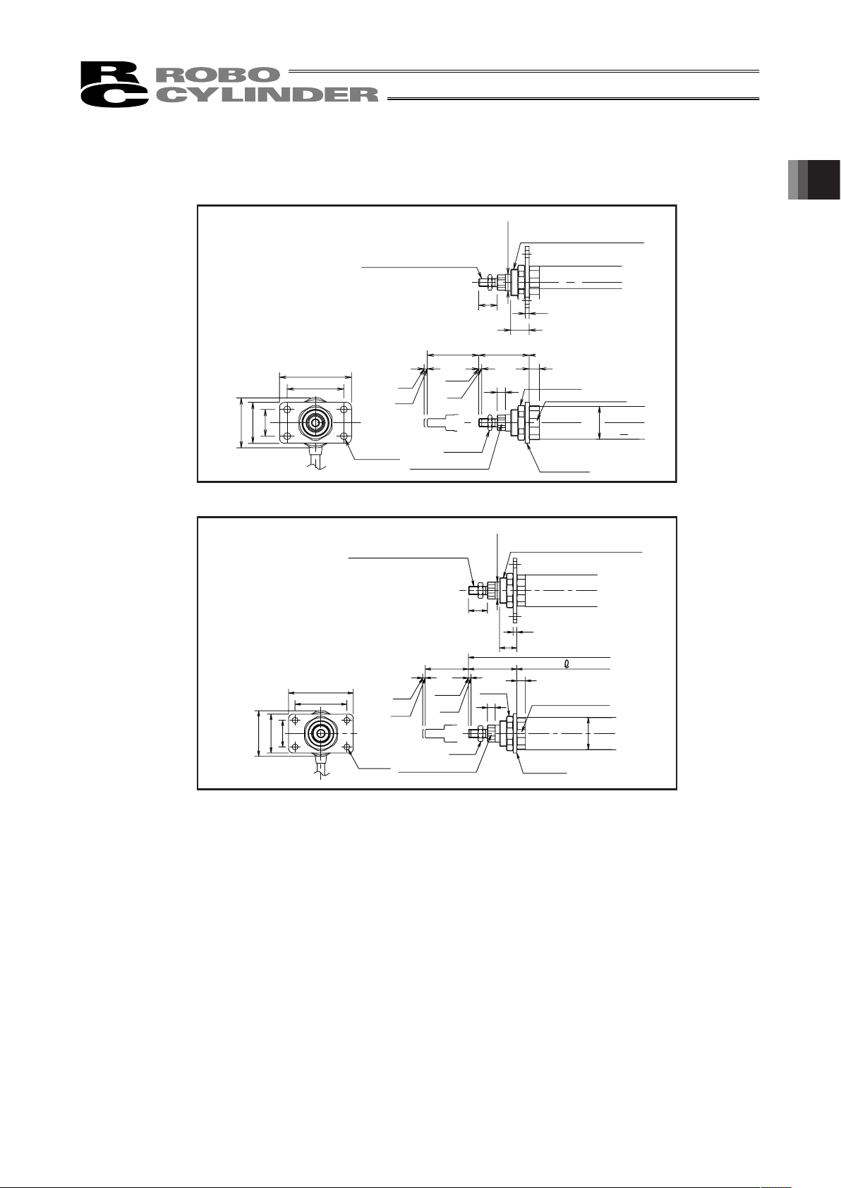
1.3.7 Front Flange (Model No. : FL)
This metal part is used for fixing the actuator from the actuator body side using the bolts.
33
SE
18
4
49st
8
55
70
26
40
48.6
10
18
RCA / RCAW-RA3 □
RCA -FL-RA 3
Model code of single product
(Effective screw range = 16)
(Effective screw range = 15.5)
φ
32
(ROD O/D)
4 - φ6.8
Nut A
φ
16
Nut C
Home
Flange
14 (Width across Flats)
32 (Width across Flats)
M8×1.25
M26×1.5
ME
ME
20
4
L
56
10
9
22
3
st
SE
75
52.8
45
31
60
RCA /
RA 4 □
RCAW /
RA 4 □
RCA -FL-RA 4
Model code of single product
(Effective screw range = 20)
(Effective screw range = 17.5)
(ROD O/D)
4 - φ6.8
Nut
φ
20
Nut
Home
Flange
19 (Width across Flats)
36(Width across Flats)
M10×1.25
M30×1.5
ME
ME
φ
37
3
1. Specications Check
Page 34

1. Specications Check
28
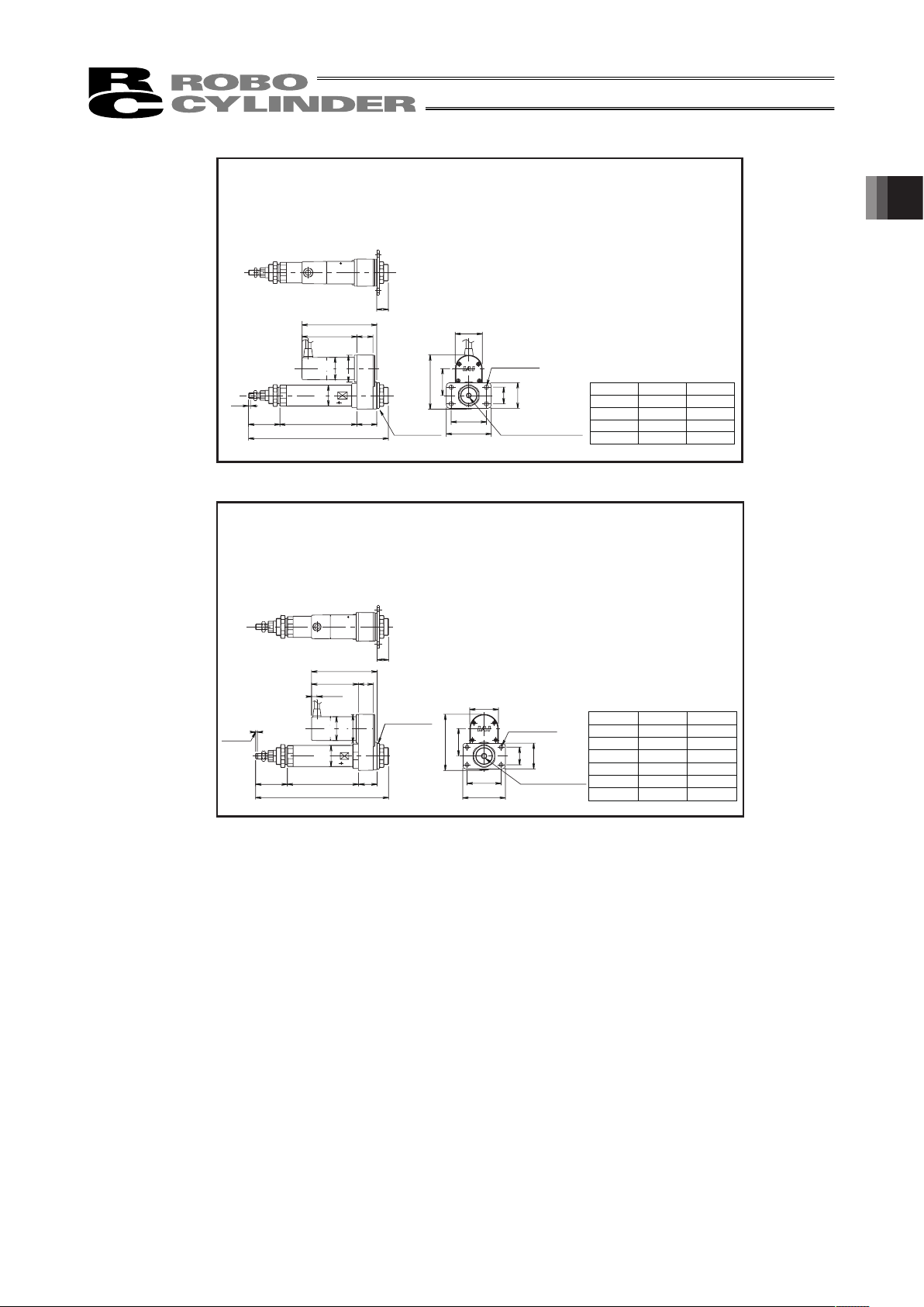
1.3.8 Rear Flange (Model No. : FLR)
This metal fitting is used for fixing the actuator from the actuator rear side.
0.25
44.5
34
5.25
75
60
10
RCA-SRA 4 R
-FL-S RA4
4-φ6.6, through
Model code of single product RCA
85
70
85.5
17
14
L149
36
50
st L1
RCA -FL R-RA3
Model code of single product
Home
Flange
40(Width
across Flats)
φ
35
φ
42
φ
32
4 - φ6.8
50
100
150
200
132
182
232
282
RCA / RCAW-RA3C, RA3D
st
50
100
150
200
250
300
L1
137
187
237
287
337
487
m
RCA
20w
67.5
80.5
80.5
30w
82.5
95.5
95.5
RCS2
55
41
90
75
16
9
m56 19L1
φ
37
φ
42
φ
50
RCA -FL R-RA4
Model code of single product
φ
37
φ
42
φ
50
Flange
Home
Nut B
4 - φ6.8
m Dimensions
Incremental
Absolute
Incremental•
Absolute
47(Width
across Flats)
RCA / RCAW-RA4C, RA4D
Page 35
29
st L1 L2
120 218
170 268
220 318
270 368
42
40
70
26
55
18
84.4
42.4
31L1
L2
49
3
116.5
25
85.5
φ
35
φ 42
φ 32
RCA -FL-RA 3
50
100
150
200
Model code of single product
*The front flange and the rear
flange can be used in common
for the motor reversing type.
φ
35
φ
42
φ
32
Flange
4 - φ6.8
M8, Depth 15
RCA / RCAW-RA3R
st L1 L2
50 125 234
100 175 284
150 225 334
200 275 384
250 325 434
300 375 484
48
82.5
115.5
45
31
75
60
50.5
98.5
L2
33L156
26
9.5
20
φ 42
φ 50
φ 37
RCA -FL-RA 4
Model code of single product
*The front flange and the rear
flange can be used in common
for the motor reversing type.
φ
37
φ
42
φ
50
Flange
Home
4 - φ6.8
M10, Depth 18
RCA / RCAW-RA4R
1. Specications Check
Page 36
1. Specications Check
30
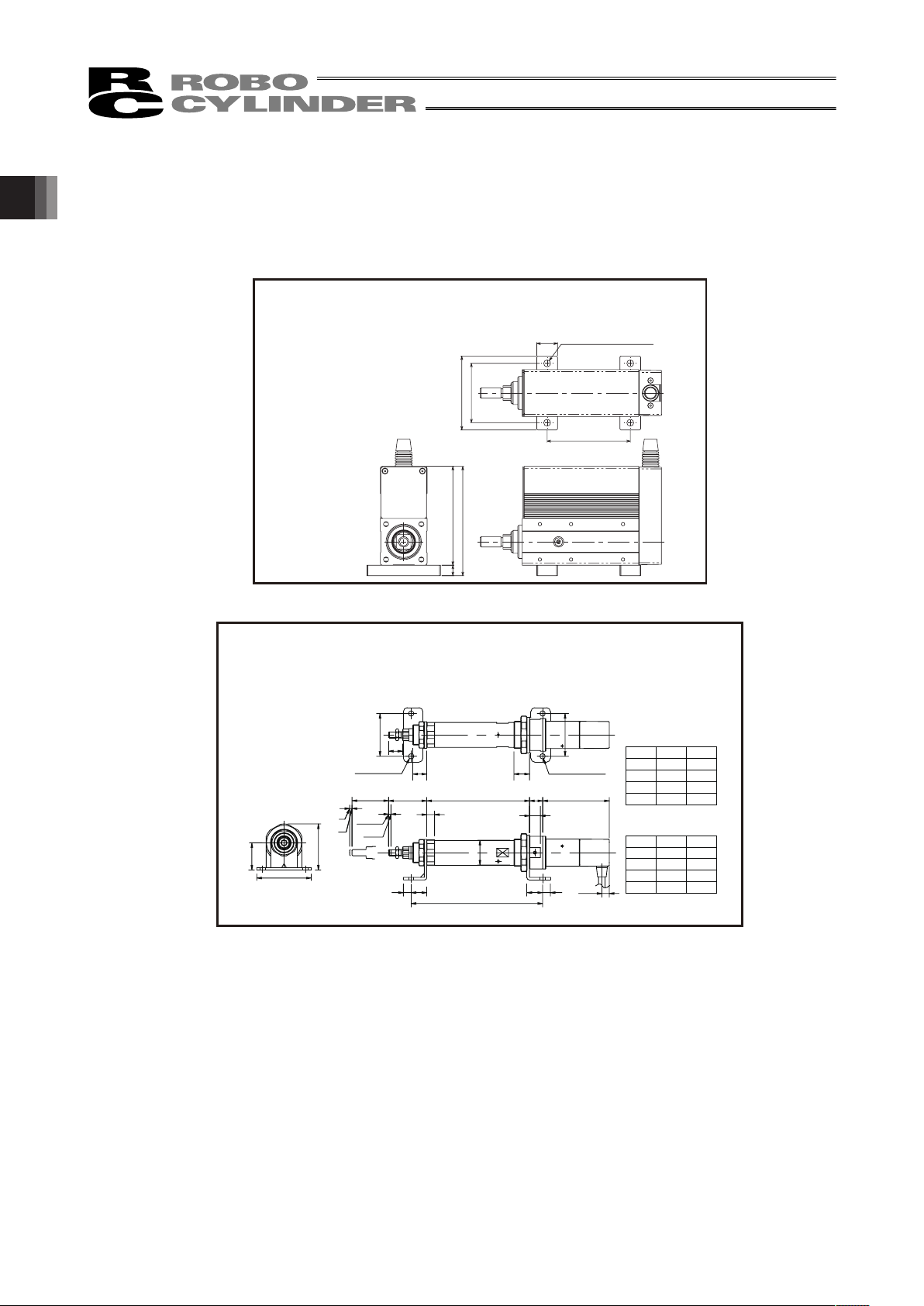
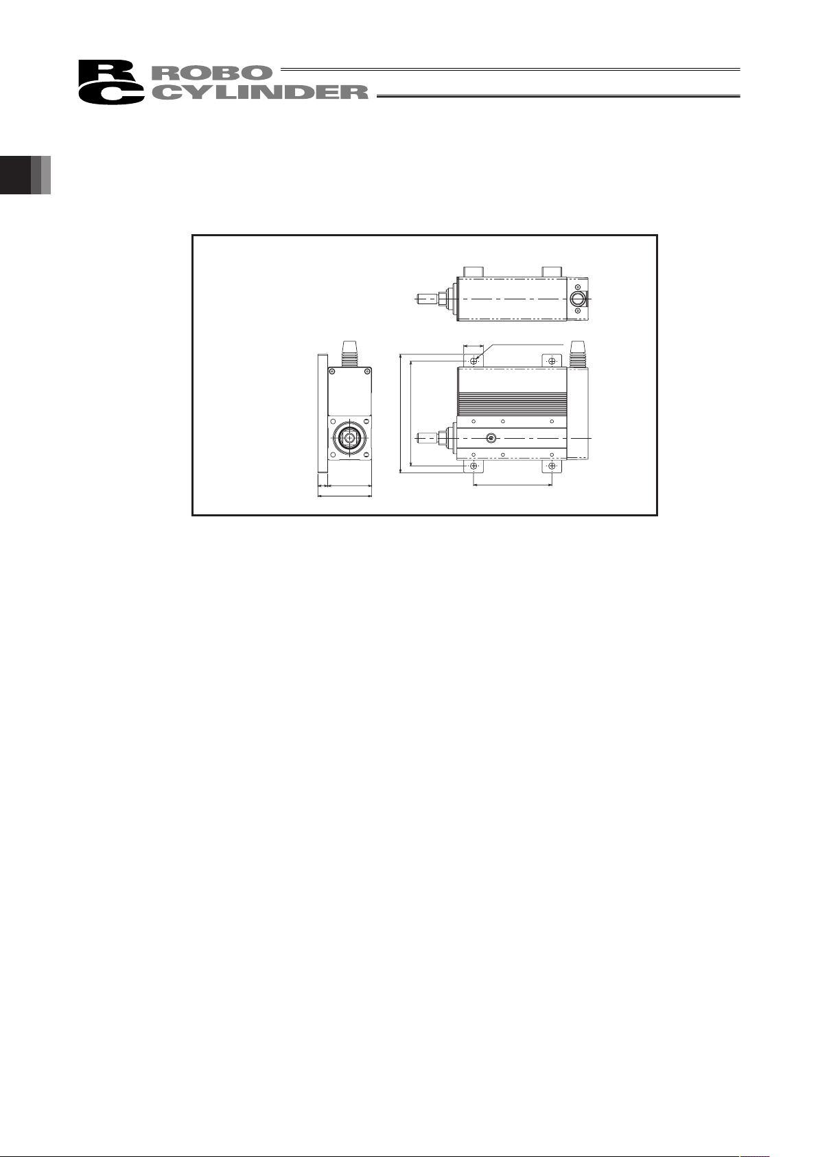
1.3.9 Foot (Model No. : FT)
This metal part is used for fixing the actuator from the top side using the bolts.
* Refer to the attachment pitch size in the drawing for each actuator, for the attachment pitch between
the foot metal parts.
st+10
71
57
20
105
95
10
RCA -SRA 4 R
Model code of single product RCA-FT-SRA4
4-φ6.6, through
50
100
150
200
140
190
240
290
176.8
226.8
276.8
326.8
L1st L2
9.5
70
59.3
35
3
3
SE
ME
18
18
20
L1
17
85.5
st
14
49
10
L2
10 20
02 01
55
55
50
100
150
200
132
182
232
282
168.8
218.8
268.8
318.8
ts 1L L2
<RGS3C/RGD3C>
<RA3C>
RCA -RA3 C / RG S 3 C / RGD 3 C
Model code of single product RCA-FT-RA3
2 - φ6.8 2 - φ6.8
ME
Home
φ
32
Page 37

31
SE
ME
20
22
22
L1
19
56
3
st
3
9.5
m
75
40
66.4
60
60
10
16
L2
10 20
02 01
<RGS4C/RGD4C>
<RA4C>
m
RCA
20w
67.5
80.5
80.5
30w
82.5
95.5
95.5
RCS2
50
100
150
200
250
300
145
195
245
295
345
495
181.8
231.8
281.8
331.8
381.8
431.8
ts 1L L2
50
100
150
200
250
300
137
187
237
287
337
487
173.8
223.8
273.8
323.8
373.8
423.8
ts 1L L2
RCA -RA 4 C / RGS 4 C / RG D4 C
Model code of single product RCA-FT-RA4
ME
Home
2 - φ6.8
2 - φ6.8
φ
37
m Dimensions
Incremental
Absolute
Incremental•
Absolute
128
178
228
278
L1
50
100
150
200
st
199
249
299
349
L2
SE
ME
9.5
85.5
25
116.5
L1
20
31
18
18
18
49st
3 3
8
10
L2 1010
34
70
35
98.2
55
55
42.4
20
<RGS3R/RGD3R>
120
170
220
270
L1
50
100
150
200
st
191
241
291
341
L2
<RA3R>
RCA / RA 3 R / RGS 3 R / RG D 3 R
Model code of single product RCA-FT-RA3R
ME
Home
2 - φ6.8
2 - φ6.8
φ
32
Model code of single product RCA-FT-RA4R
ME
Home
2 - φ6.8
50
100
150
200
250
300
133
183
233
283
333
383
206
256
306
356
406
456
L1st L2
ME
SE
st
22
9.5
26
L1
3
3
82.5
115.5
20
20
33
φ
37
56
10
9
L2
10
10
39
75
40
113.2
60
50.5
20 20
<RGS4R/RGD4R>
50
100
150
200
250
300
125
175
225
275
325
375
198
248
298
348
398
448
ts 1L L2
<RA4R>
RCA -RA 4 R / RGS 4 R / RG D4 R
Nut A
2 - φ6.8
1. Specications Check
Page 38
1. Specications Check
32
1.3.10 Foot (Attached on the Right Side/Left Side)
(Model No.: FT2 (Attached on the Right Side), FT4 (Attached on the Left Side)
This metal part is used for fixing the actuator from the top side using the bolts. For RCA-SRA4R, the
actuator can be attached also to the side.
st+10
121
107
20
55
45
10
RCA-S RA 4 R
4 - φ6.6, through
Model code of single product
RCA-FTS-SRA4
Page 39

33
1.3.11 Knuckle Joint (Model No. : NJ)
This metal part is used to give some degree of freedom (rotation) in the movement at the rod end of the
actuator when Clevis or trunnion part is used.
16
25 25 10
16
Joint Pin
Joint S
Joint W
Nut
M8×1.25 Depth 11
For RCA-RA3□
Model code of single product RCA-NJ-RA3
20
30 30 11
20
Joint Pin
Joint S
Joint W
Nut
M10×1.25 Depth 13
For RCA-RA4□
Model code of single product
RCA-NJ-RA4
1. Specications Check
Page 40
1. Specications Check
34
1.3.12 Clevis (Model No. : QR)
This bracket is used to make the cylinder follow up when the movement of an object attached on the tip
of the rod is different from the direction of rod movement. Attach on the rod.
φ
32
3 3
8
49
10
9.5
85.5
L
18 18
116.5
25
15
27
31
ME
ME
15
M4
42.4
22.4
55
40
42
103.2
75
st
SE
50
100
150
200
120
170
220
270
227
277
327
377
st
L
RCA-RA3 R
Model code of single product
RCA-QR-RA3
2 - φ6.8
Nut A
Nut B
Home
32 (Width across Flats)
14 (Width across Flats)
φ
42
φ
35
Clevis
22
20
L
15
55
75
115.5
9.5
3
3
9 10
56
82.5
33
26
28
16
M4
50.5
26.4
48
98.5
ME
ME
st
SE
40
50
100
150
200
250
300
125
175
225
275
325
375
242
292
342
392
442
492
st
L
RCA -R A 4 R
Model code of single product
RCA-QR-RA4
2 - φ9
Nut A
Nut B
Home
φ
37
32 (Width
across Flats)
14 (Width across Flats)
φ42φ
50
Clevis
φ
20
(ROD O/D)
Caution: Attach the external guide so that any load is not given to the rod other than in the forward
direction, when the Clevis bracket is attached and rod is moved.
Page 41

35
1.3.13 Rear Attachment Plate (Model No. : RP)
This plate is used to fix the rear side of the motor reversing rod type (RA3R/RA4R) onto the system.
φ
32
φ
42
φ
35
3 3
49
8 10
9.5
85.5 25
116.5
L
31 2.5
42.4
4-M4
st
0
42
84.4
SE
ME
ME
φ
34
Model code of single product
RCA-RP-RA3
Home
φ
26h9 (-0.052)
φ
16(ROD O/D)
14(Width across Flats)
32(Width across Flats)
Nut A
Nut B
For RCA-RA3R
9.5
82.5
115.5
26
3
9
10
56
st
0
SE
ME
ME
33 2.5 50.5
L
4-M4
48
98.5
Model code of single product
RCA-RP-RA4
Home
φ
37
φ
50
φ
42
φ
39
φ
30h9 (-0.052)
φ
20(ROD O/D)
14(Width across Flats)
32(Width
across Flats)
Nut A
Nut B
For RCA-RA4R
1. Specications Check
Page 42

1. Specications Check
36
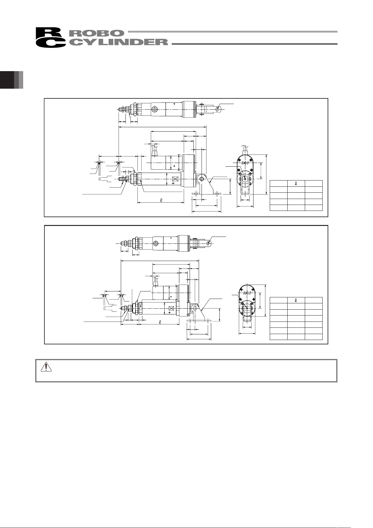
1.3.14 Front Trunnion (Model No. : TRF)
This bracket is used to make the cylinder follow up when the movement of an object attached on the tip
of the rod is different from the direction of rod movement. Attach on the rod.
φ
32
φ
42
φ
35
Model code of single product
RCA-TRF-RA3
14(Width
across Flats)
32(Width across Flats)
Nut A
For RCA-RA3□
9.5
33
SE
ME
18
20
49
10
st
90
64.3
40
40
70
8
60
5
10
55
M8×1.25 (Effective screw range = 16)
M35×1.5
(Effective screw range = 17.5)
φ
16 (ROD O/D)
2-φ6.8
40(Width across Flats)
Home
Nut C
Bracket A
Ring
Bracket B
ME
φ
20 (ROD O/D)
22
3
9
55610
55
3
10
st
ME
ME
SE
94
64
40
22
74
9.5
66.4
40
M10×1.25 (Effective screw range = 20)
M40×1.25
(Effective screw range = 19.5)
φ
37
19(Width
across Flats)
36(Width across Flats)
47(Width across Flats)
Home
Nut C
Bracket A
Ring
Bracket B
Model code of single product
RCA-TRF-RA4
For RCA-RA4□
Caution: Use the guide equipped type or attach the external guide so that any load is given to the rod
other than in the forward direction, when the trunnion is attached and the rod is moved.
Page 43

37
1.3.15 Rear Trunnion (Model No. : TRR)
This bracket is used to make the cylinder follow up when the movement of an object attached on the tip
of the rod is different from the direction of rod movement. Attach on the rod.
9.5
33
SE
49st
8
40
83
10
73
103
40
64.3
10
55
18
φ
32
φ
42
φ
35
Model code of single product
RCA-TRR-RA3
For RCA-RA3□
Bracket A
Bracket B
2-φ6.8
M26×1.5
(Effective screw range = 15.5)
M8×1.25 (Effective screw range = 16)
φ
16 (ROD O/D)
14(Width
across Flats)
32(Width across Flats)
Nut A
40(Width across Flats)
Home
Nut C
ME
ME
3
ME
ME
9
56
st
SE
9.5
107
77
40
20
22
10
10
40
87
66.5
φ
37
Model code of single product
RCA-TRR-RA4
For RCA-RA4□
φ
20 (ROD O/D)
M10×1.25 (Effective screw range = 20)
M40×1.25
(Effective screw range = 17.5)
36(Width across Flats)
47(Width across Flats)
Nut A
19(Width across Flats)
Home
Nut C
Caution: Use the guide equipped type or attach the external guide so that any load is given to the rod
other than in the forward direction, when the trunnion is attached and the rod is moved.
1. Specications Check
Page 44

1. Specications Check
38
1.4 Motor • Encoder Cables
1.4.1 Motor cable
CB-ACS-MA ƑƑƑ
1.4.2 Encoder cable/robot encoder cable
CB-ACS-PA ƑƑƑ/CB-ACS-PA ƑƑƑ-RB
Controller end
Actuator end
Width
Cable
Color
Signal
Name
Pin
No.
Red U 1 1 U Red
White V 2 2 V White
AWG22
(crimped)
Black W 3 3 W Black
AWG22
(crimped)
1
3
Width
Cable
Color
Signal
Name
Pin
No.
Controller end
Actuator end
AWG26
(
crimped
)
White/purple
White
/
purple
White/gray
White/gray
Yellow
Yellow
Blue
Blue
White/blue
White/blue
White/yellow
White/yellow
White/red
White/red
White/black
White/black
Orange
Orange
Green
Green
Purple
Purple
Gray
Red
Black
Drain
Black
Gray
Red
-
-
-
-
-
-
LS +
LS -
BK +
BK -
A +
A -
B +
B -
SD/Z +
SD/Z -
BAT +
BAT -
VCC
GND
-
-
-
FG
1
2
3
4
5
6
7
8
9
10
11
12
13
14
15
16
17
18
18
17
16
15
14
13
12
11
10
9
8
7
6
5
4
3
2
1
A +
A -
B +
B -
-
-
-
-
-
-
-
-
LS + LS +
-
-
FG FG
Z +
Z -
-
/PS
BAT +
BAT -
SD +
SD -
VCC
GND
VCC
GND
LS -
BK +
BK -
LS -
BK +
BK -
AWG26
(crimped)
18 17
2 1
9 18
1 10
Width
Cable
Color
Signal
Name
Pin
No.
Pin
No.
Width
Cable
Color
Signal Name
For ABZ For Serial
Drain
Page 45

39
1.4.3 Motor/Encoder Integrated Cable for AMEC/ASEP
CB-ASEP-MPA ƑƑƑ
Controller end
Actuator end
Width
Cable Color
Signal
Name
Pin
No.
1
2
3
18
17
7
16
1
2
3
4
10
11
14
13
15
6
5
8
12
9
Identification Tape
U
V
NC
NC
W
NC
BK+
BK-
LS+
LS-
A+
A-
B+
B-
Z+
Z-
VCC
VPS
GND
Spare
NC
NC
NC
FG
AWG22
(crimped)
AWG26
(crimped)
Red
Yellow
Black
Orange
Gray
Black
Brown
White
Yellow
Red
Green
Black
Brown
White
Yellow
Red
Green
Width
Cable Color
Signal
Name
Pin
No.
1
2
3
4
5
6
7
8
9
10
11
12
13
14
15
16
17
18
19
20
21
22
23
24
U
V
NC
NC
W
NC
BK+
BK-
LS+
LS-
A+
A-
B+
B-
Z+
Z-
VCC
VPS
GND
Spare
NC
NC
NC
FG
AWG22
(crimped)
AWG26
(crimped)
Red
Yellow
Black
Orange
Gray
Black
Brown
White
Yellow
Red
Green
Black
Brown
White
Yellow
Red
Green
Identification Tape
1. Specications Check
Page 46

2. Installation
40
2. Installation
2.1 Transportation
[1] Handling of Robot
Unless otherwise specified, the actuators are packaged individually.
(1) Handling the Packed Unit
y Do not damage or drop. The package is not applied with any special treatment that enables it to resist
an impact caused by a drop or crash.
y Transport a heavy package with at least more than two operators. Consider an appropriate method for
transportation.
y Keep the unit in horizontal orientation when placing it on the ground or transporting. Follow the
instruction if there is any for the packaging condition.
y Do not step or sit on the package.
y Do not put any load that may cause a deformation or breakage of the package.
(2) Handling the Actuator After Unpacking
y Do not attempt to carry the actuator with holding a cable or move it by pulling a cable.
y Hold either the base part or the bracket part when transporting the actuator main body.
y Do not hit or drop the actuator during transportation.
y Do not carry an actuator by motor unit and a cable or attempt to move it by pulling the cable.
Page 47

41
[2] Handling in Assembled Condition
This is the case when the product is delivered from our factory under a condition that it is assembled
with other actuators. The combined axes are delivered in a package that the frame is nailed on the
lumber base. The rods are fixed so they would not accidently move. The actuators are also fixed so the
tip of it would not shake due to the external vibration.
(1) How to Handle in Package
y Do not hit or drop the package. No special treatment is conducted on this package to endure a drop or
impact on it.
y Do not attempt to carry a heavy package with only one worker. Also, have an appropriate method for
transportation.
y When hanging up with ropes, support on the reinforcement frame on the bottom of the lumber base.
When bringing up the package with a forklift, also support on the bottom of the lumber base.
y Handle with care when putting the package down to avoid impact or bounce.
y Do not step on the package.
y Do not put anything on the package that could deform or damage it.
(2) How to Handle after Unpackaged
y Fix the rod so they would not accidently move during transportation.
y If the tip of an actuator is overhanging, have an appropriate way to fix it to avoid shake due to the
external vibration. In the transportation without the tip being fixed, do not apply any impact with 0.3G or
more.
y When hanging up with ropes, have appropriate cushioning to avoid any deformation of the actuator
body. Also keep it in stable horizontal orientation. Make a fixture utilizing the attachment holes and the
tapped holes on the actuator body if necessary.
y Do not attempt to apply load on the actuators or the connector box. Also pay attention not to pinch
cables and bend or deform them forcefully.
[3] Handling in Condition of being assembled in Machinery Equipment (System)
This is some caution notes for when transporting the actuator being assembled in the machinery
equipment (system).
y Fix the cables so they would not move during transportation.
y If the tip of an actuator is overhanging, have an appropriate way to fix it to avoid shake due to the
external vibration. In the transportation without the tip being fixed, do not apply any impact with 0.3G or
more.
y When hanging up the machinery equipment (system) with ropes, do not attempt to apply load on the
actuators or the connector box. Also pay attention not to pinch cables and bend or deform them
forcefully.
2. Installation
Page 48

2. Installation
42
2.2 Installation and Storage • Preservation Environment
[1] Installation Environment
The actuator should be installed in a location other than those specified below.
In general, the installation environment should be one in which an operator can work without protective
gear.
Also provide sufficient work space required for maintenance inspection.
y Where the actuator receives radiant heat from strong heat sources such as heat treatment furnaces
y Where the ambient temperature exceeds the range of 0 to 40qC
y Where the temperature changes rapidly and condensation occurs
y Where the relative humidity exceeds 85% RH
y The product will possess water-proof performance of the protection structure of IP65 if air purge is
conducted.
y Where the actuator receives direct sunlight
y Where the actuator is exposed to corrosive or combustible gases
y Where the ambient air contains a large amount of powder dust, salt or iron (at level exceeding what
is normally expected in an assembly plant)
y Where the actuator is subject to splashed water, oil (including oil mist or cutting fluid) or chemical
solutions
y Where the actuator receives impact or vibration
If the actuator is used in any of the following locations, provide sufficient shielding measures:
y Where noise generates due to static electricity, etc.
y Where the actuator is subject to a strong electric or magnetic field
y Where the actuator is subject to ultraviolet ray or radiation
[2] Storage • Preservation Environment
y The storage and preservation environment should comply with the same standards as those for the
installation environment. In particular, when the machine is to be stored for a long time, pay close
attention to environmental conditions so that no dew condensation forms.
y Unless specially specified, moisture absorbency protection is not included in the package when the
machine is delivered. In the case that the machine is to be stored and preserved in an environment
where dew condensation is anticipated, take the condensation preventive measures from outside of
the entire package, or directly after opening the package.
y For storage and preservation temperature, the machine withstands temperatures up to 60qC for a
short time, but in the case of the storage and preservation period of 1 month or more, control the
temperature to 50qC or less.
y Storage and preservation should be performed in the horizontal condition. In the case it is stored in
the packaged condition, follow the posture instruction if any displayed on the package.
Page 49

43
2.3 How to Installation
This chapter explains how to install the actuator on your mechanical system.
2.3.1 General Rules on Installation
Follow the information below when installing the actuator, as a rule.
Do pay attention to these items (except with custom-order models).
{: Available u : Not available
Horizontally Oriented Mount Vertical Mount
ż ż
Caution: When the unit is installed vertically oriented, attempt to put the motor up unless there
is a special reason. Putting the motor on the lower side would not cause a problem in
an ordinary operation. However, it may rarely cause a problem, when it is not
operated for a long period, depending on the surrounding environment (especially
high temperature), caused by the grease being separated and the base oil flowing into
the motor unit.
2. Installation
Page 50

2. Installation
44
2.3.2 Installation
(1) Using screws on the rod or head side
Install the actuator using screws set on the rod or head side of the actuator.
z Applicable models: All models
Type MA MB
RA3 type
M26u1.5 M35u1.5
RA4 type
M30u1.5 M40u1.5
Straight type
Rod cove
r
Cylinder tube
Head cove
r
Motor unit
Reversing type
MA
MB
Pulley case
Rod
Rod cove
r
MA
Cylinder tube Head cove
r
MA
Page 51
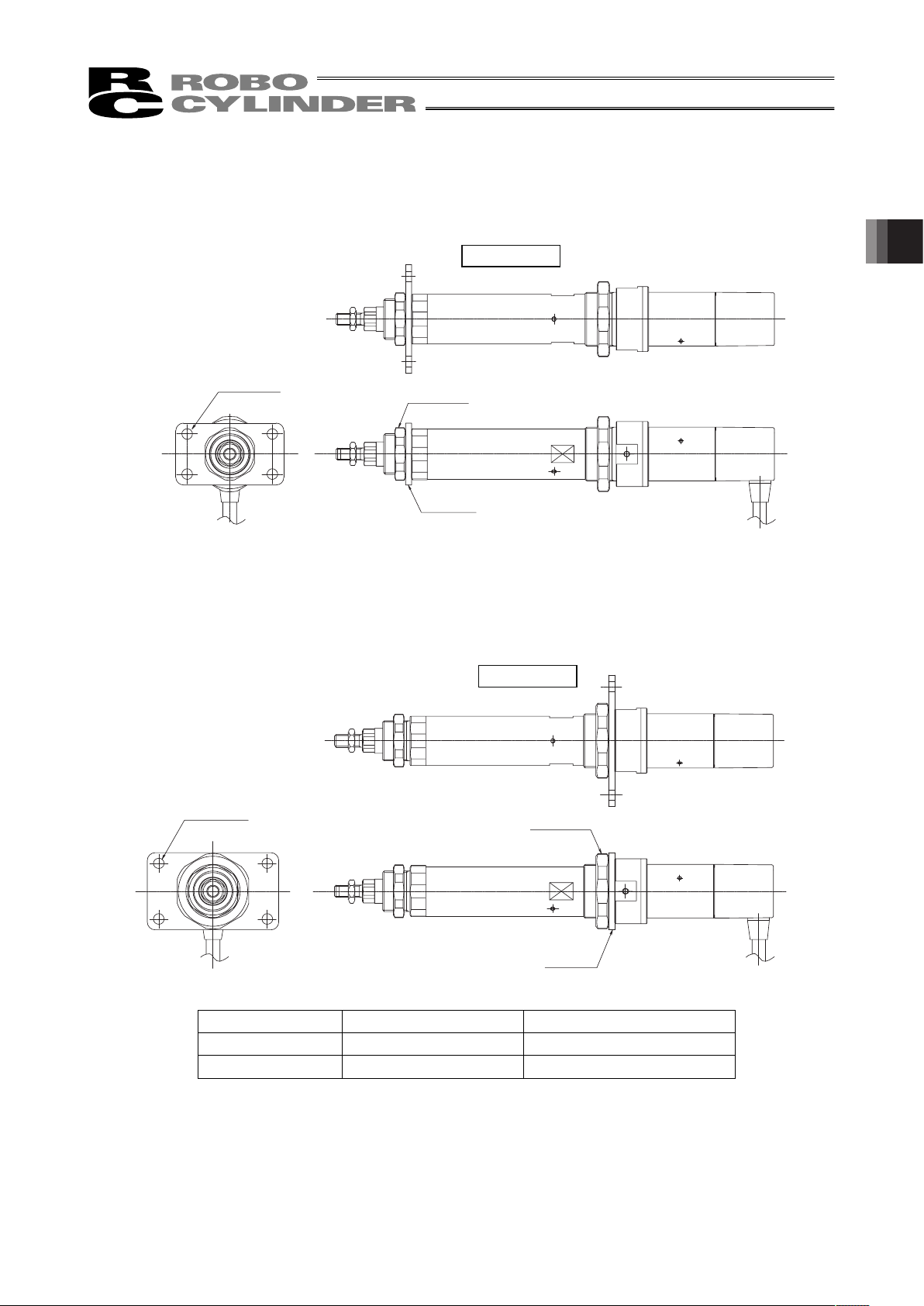
45
(2) Using screws on a flange (optional)
An optional flange is available for installing the actuator. Use this flange, if necessary.
z Applicable models: All models
Mating material is steel Mating material is aluminum
Screw size M6 M6
Tightening torque 12.3 N•m 5.4 N•m
Straight type
Mounting hole
Affixing nut
Flange
Straight type
Mounting hole
Affixing nut
Flange
2. Installation
Page 52
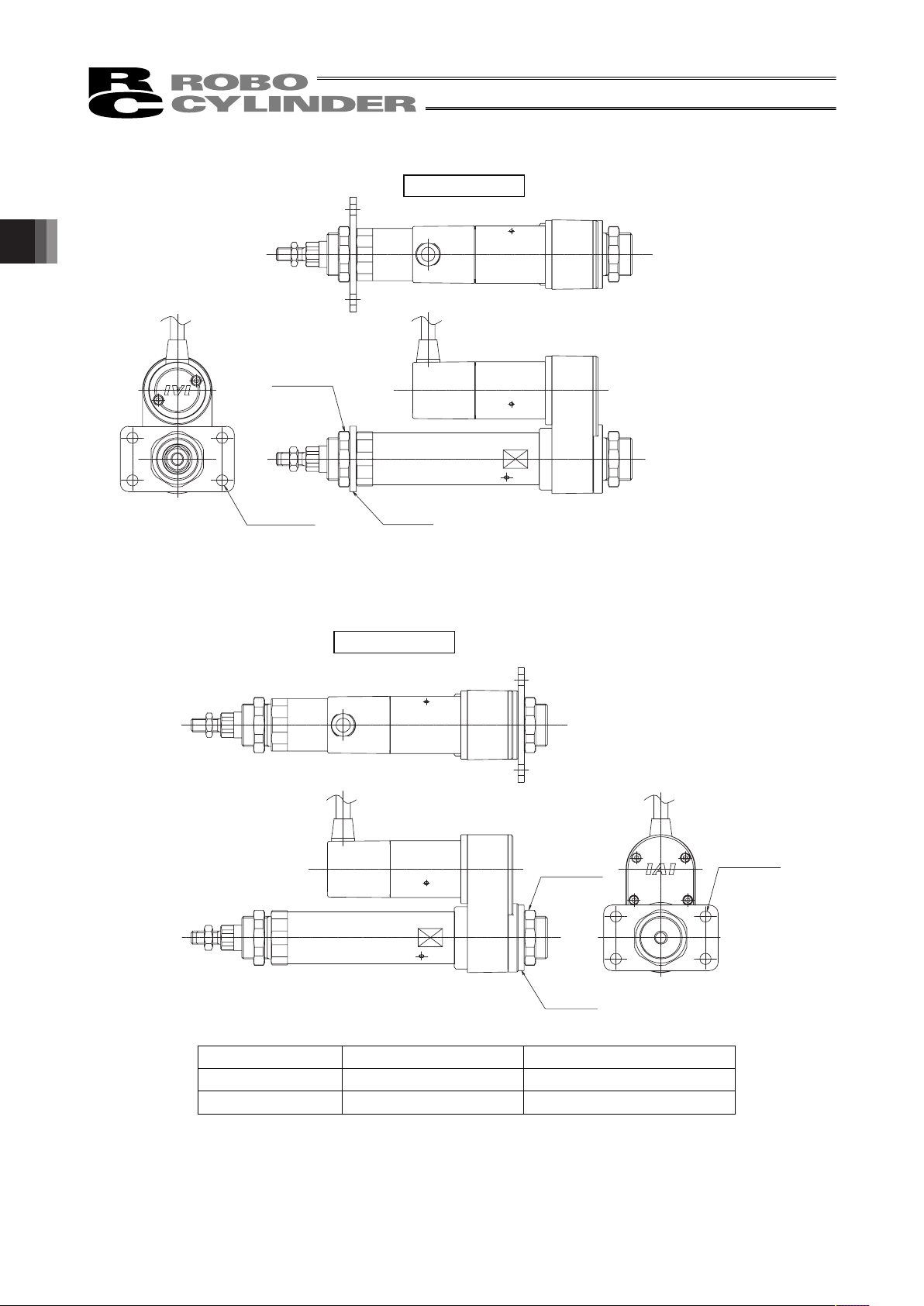
2. Installation
46
Mating material is steel Mating material is aluminum
Screw size M6 M6
Tightening torque 12.3 N•m 5.4 N•m
Reversing type
Mounting hole
Affixing nut
Flange
Mounting hole
Affixing nut
Flange
Reversing type
Page 53

47
(3) Using screws on feet (optional)
Optional feet are available for installing the actuator. Use these feet, if necessary.
z Applicable models: All models
Mating material is steel Mating material is aluminum
Screw size M6 M6
Tightening torque 12.3 N•m 5.4 N•m
Caution: Affix the actuator using two feet (optional), one in the front and the other in the back.
If affixed using only one foot in the front or back, the actuator may be negatively
affected due to insufficient rigidity.
Straight type
Mounting hole
Affixing nut
Foot A
Affixing nut
Affixing nut
Mounting hole
Foot B
Reversing type
Mounting hole
Mounting hole
Affixing nut
Foot
Foot
2. Installation
Page 54

2. Installation
48
(4) Using screws on a trunnion (optional)
An optional trunnion is available for installing the actuator. Use this trunnion, if necessary.
z Applicable models: RA3C, RA3D, RA4C, RA4D
Mating material is steel Mating material is aluminum
Screw size M6 M6
Tightening torque 12.3 N•m 5.4 N•m
Straight type
Mounting hole
Affixing nut
Trunnion ring
Straight type
Mounting hole
Affixing nut
Bracket B
Bracket A
Trunnion ring
Bracket A
Bracket B
Page 55

49
Mating material is steel Mating material is aluminum
Screw size M6 M6
Tightening torque 12.3 N•m 5.4 N•m
Caution: y When the optional Clevis, Trunnion or commercially available free joint is attached
and the actuator is installed horizontally, take the greatest care because the weight
of the actuator is given to the rod. Otherwise, the bush might be worn out earlier or
inside mechanism might be damaged.
Add the guide mechanism, etc., so that the weight of the actuator is not given to the
rod.
y For the load given to the optional Clevis or Trunnion fulcrum shaft, only the radial
load is allowed. In the case of the conditions that the backlash is not allowed or thrust
load is given, the user should design the bearing structure.
y The optional Clevis or Trunnion has the structure that the bearing selects the fulcrum
shaft. Apply grease onto the fulcrum shaft.
Mounting hole
Affixing nut
Trunnion ring
Bracket A
Bracket B
Reversing type
2. Installation
Page 56
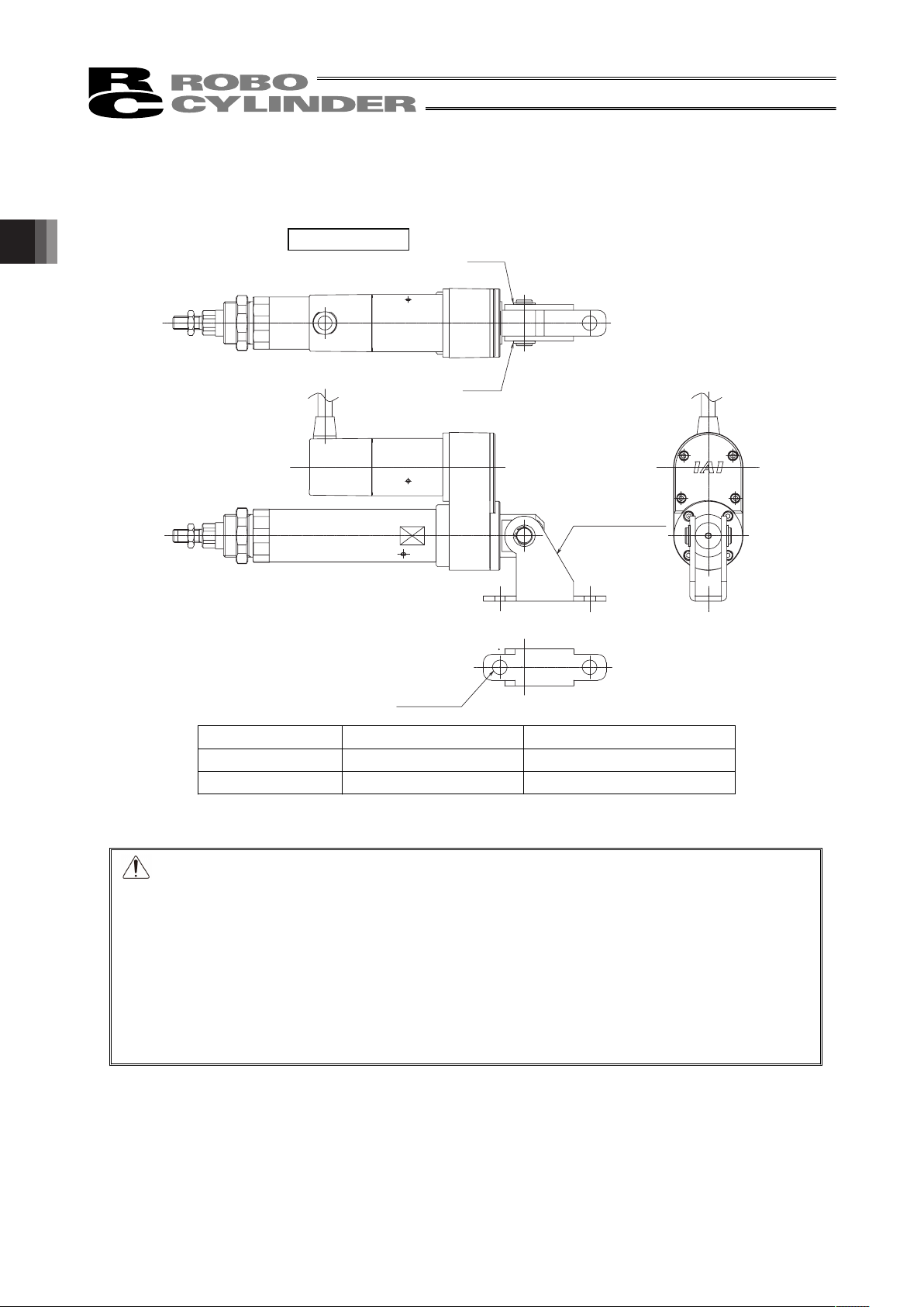
2. Installation
50
(5) Using screws on a clevis (optional)
An optional clevis is available for installing the actuator. Use this clevis, if necessary.
z Applicable models: Motor reversing type RCA-RA3R, RCA-RA4R
Mating material is steel Mating material is aluminum
Screw size M8 M8
Tightening torque 30 N•m 12 N•m
Caution: y When the optional Clevis, Trunnion or commercially available free joint is attached
and the actuator is installed horizontally, take the greatest care because the weight
of the actuator is given to the rod. Otherwise, the bush might be worn out earlier or
inside mechanism might be damaged.
Add the guide mechanism, etc., so that the weight of the actuator is not given to the
rod.
y For the load given to the optional Clevis or Trunnion fulcrum shaft, only the radial
load is allowed. In the case of the conditions that the backlash is not allowed or thrust
load is given, the user should design the bearing structure.
y The optional Clevis or Trunnion has the structure that the bearing selects the fulcrum
shaft. Apply grease onto the fulcrum shaft.
Mounting hole
Reversing type
Stopper ring
Stopper ring
Clevis bracket
Page 57
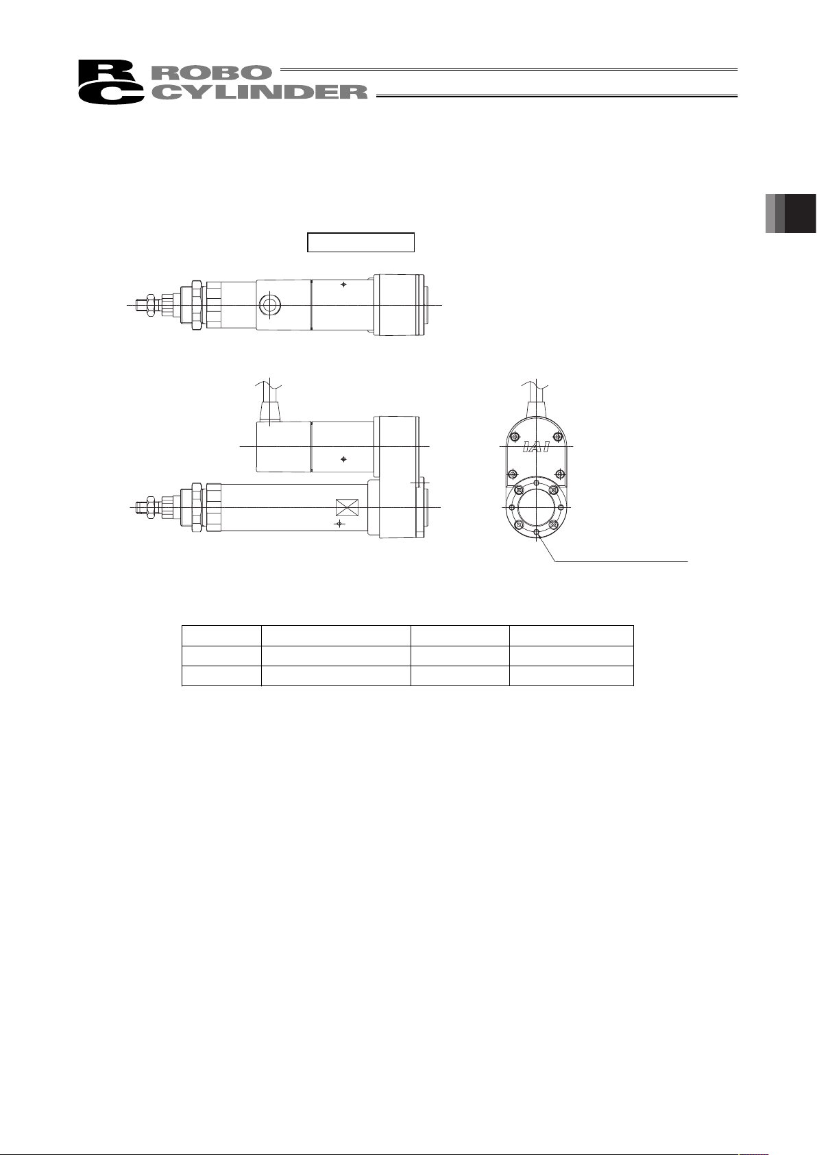
51
(6) Using screws on a rear mounting bracket (optional)
An optional rear mounting bracket is available for installing the actuator. Use this rear mounting bracket,
if necessary.
z Applicable models: Motor reversing type RCA-RA3R, RCA-RA4R
Type Tapped hole diameter Tapped depth Tightening torque
RA3 type M4 6 mm 1.8 N•m
RA4 type M4 7 mm 1.8 N•m
Reversing type
Tapped mounting hole
2. Installation
Page 58

2. Installation
52
(7) Double-guide type
Use the tapped holes in the bracket for installing an actuator of the double-guide type.
z Applicable models: Double-guide type RGD3, RGD4
Type Tapped hole diameter Tapped depth Tightening torque
RA3 type M5 8 mm 3.4 N•m
RA4 type M5 8 mm 3.4 N•m
Tapped mounting hole
Bracket A
Bracket B
Page 59

53
(8) Single-guide type
Use the tapped holes in the bracket for installing an actuator of the single-guide type.
z Applicable models: Double-guide type RGD3, RGD4
Type Tapped hole diameter Tapped depth Tightening torque
RA3 type M5 8 mm 3.4 N•m
RA4 type M5 8 mm 3.4 N•m
Tapped mounting hole
Bracket A
Bracket B
2. Installation
Page 60

54
2.3.3 Connecting the Air Tube of the RCAW Dustproof/Splash-proof Type
Intake/exhaust port
Install the air tube (outer diameter: 10 mm, inner diameter: 6.5 mm) on the intake/exhaust port and guide the
air tube to a location where the external environment assures the tube will not come in contact with water.
(Applicable tube)
Shown below is a representative model of air tube that can be installed on the RCAW:
• TU1065: Polyurethane tube (Manufacturer: SMC)
Caution: The air tube should not be more than 3 m long.
2. Installation
Page 61

55
3. Connecting with Controller
For the controller, only the dedicated controller manufactured by our company can be used.
Usage of an undedicated controller may cause accidents such as burnout, ignition or heat generation.
For the connection between the actuator and controller, use the attached dedicated connection cable.
[Connection to the ACON, ASEL controller]
Dedicated Connection Cable
y Motor Cable (Robot Cable) CB-RCP2-MA***
y Encoder Cable CB-RCP2-PB***/Encoder Cable Robot Cable CB-RCP2-PB***-RB
*** shows the cable length. The max. length should be 20m.
Example) 080=8m
[Connection to the AMEC, ASEP controller]
Dedicated Connection Cable
y Motor Encoder Cable CB-ASEP-MPA***
*** shows the cable length. The max. length should be 20m.
Example) 080=8m
RCA, RCACR, RCAW
r
r
Dedicated Controller
ACON
ASEL
Dedicated Connection Cable
(Connect RCA, RCACR or RCAW with the dedicated controller.)
Robot Cable
r = 54mm or more (Movable Use)
Standard Cable
r = 75mm or more (Fixed Use)
Use robot cables if the cables tend to move.
r
Dedicated Controller
AMEC, ASEP
RCA, RCACR, RCAW
r = 68mm or more (Movable Use)
r = 34mm or more (Fixed Use)
Dedicated Connection Cable
(Connect RCA, RCACR or RCAW with the dedicated controller.)
3. Connecting with Controller
Page 62

3. Connecting with Controller
56
Warning: For wiring, please follow the warnings stated below. When constructing a system
as the machinery equipment, pay attention to the wiring and connection of each
cable so they are conducted properly. Not following them may cause not only a
malfunction such as cable breakage or connection failure, or an operation error,
but also electric shock or electric leakage, or may even cause a fire.
• Use dedicated cables of IAI indicated in this instruction manual. Contact us if you wish to
have a change to the specifications of the dedicated cables.
• Make sure to turn the power off in the process of power line or cable connection or
disconnection.
• Do not attempt to cut a dedicated cable with connectors on both ends to extend, shorten
or re-joint it.
• Hold the dedicated cable to avoid mechanical force being applied to the terminals and
connectors.
• Use a cable pipe or duct to have an appropriate protection when there is a possibility of
mechanical damage on a dedicated cable.
• In case a dedicated cable is to be used at a moving part, make sure to lay out the cable
without applying any force to pull the connector or extreme bend on the cable. Do not
attempt to use the cable with a bending radius below the allowable value.
• Make certain that the connectors are plugged properly. Insufficient connection may cause
an operation error, thus it is extremely risky.
• Do not lay out the cables to where the machine runs over them.
• Pay attention to the cable layout so it would not hit peripherals during an operation. In
case it does, have an appropriate protection such as a cable track.
• When a cable is used hanging on the ceiling, prevent an environment that the cable
swings with acceleration or wind velocity.
• Make sure there is not too much friction inside the cable storage equipment.
• Do not apply radiated heat to power line or cables.
• Have a sufficient radius for bending, and avoid a bend concentrating on one point.
Steel Strap
(Piano Wire)
Tie them up softly.
• Do not let the cable bend, kink or twist.
Page 63

57
• Do not pull the cable with a strong force.
• Pay attention not to concentrate the twisting force to one point on a cable.
• Do not pinch, drop a heavy object onto or cut the cable.
• When a cable is fastened to affix, make sure to have an appropriate force and do not
tighten too much.
Do not use spiral tube in any
position where cables are bent
frequently.
• PIO line, communication line, power and driving lines are to be put separately from each
other and do not tie them together. Arrange so that such lines are independently routed in
the duct.
Power Line
Duct
I/O Line
(Flat Cable, etc.)
3. Connecting with Controller
Page 64

58
• If using a cable track, arrange the wiring so that there is no entanglement or kink of the
cables in the cable carrier or flexible tube, and do not bind the cables so that the cables
are relatively free. (Arrange the wiring so the cables are not to be pulled when bent.)
• The occupied volume rate for the cables, etc., inside the cable track should be 60% or
less.
Cable
Cable Track
3. Connecting with Controller
Page 65

59
4. Maintenance
4.1 Maintenance Schedule
Perform maintenance work according to the schedule below.
The schedule is set assuming eight hours of operation a day. When the operation time is long such as
24-hour operation, shorten the maintenance intervals as needed.
Visual inspection Grease supply
*1
Start of operation
{
After 1 month of operation
{
After 3 months of operation
{
Every 3 months thereafter
{
{ (Sliding surface of the rod)
*1
After 3 years of operation, or upon
reaching 5,000 km in traveled distance
{
{ (Sliding surface of the rod)
*1
Every year thereafter
{
*1 Apply grease to the sliding surface of the rod at the startup check if grease has been consumed, or
every three months.
For the RCAW dustproof/splash-proof type, apply grease when the bellows is changed.
4.2 Visual Inspection of the Machine
Exterior Check the following items visually.
Body Loose mounting bolts?
Cables Damage to cables or connection to connector box?
General Unusual noise or vibrations?
4.3 Cleaning
y Clean the exterior as needed.
y Wipe off dirt with a soft cloth.
y Do not use strong compressed air on the actuator as this may force dust into the crevices.
y Do not use petroleum-based solvent on plastic parts or painted surfaces.
y If the unit is badly soiled, apply a neutral detergent or alcohol to a soft cloth, and wipe gently.
4. Maintenance
Page 66

4. Maintenance
60
4.4 Applying Grease to the Sliding Surface of the Rod
(1) Applicablegrease
KyodoYushi MultempLRL3
Warning: Never use any fluorine-based grease.
It will cause a chemical reaction when mixed with a lithium-based grease and may cause
damage to the actuator.
(2) How to apply grease
Apply grease over the entire surface of the rod.
Caution: In case the grease got into your eye, immediately go to see the doctor to get an
appropriate care.
After finishing the grease supply work, wash your hands carefully with water and soap
to rinse the grease off.
Page 67

61
4.5 Reduction Belt [Motor Reversing Type]
4.5.1 Inspecting the Belt
Remove the pulley cover and visually inspect the belt.
Durability of the reduction belt is affected significantly by the operating condition, and there is no
standard guideline as to when the belt should be replaced.
Generally, the belt is designed to withstand several millions of flexing loads.
As a practical guideline, replace the reduction belt when any of the conditions listed below is observed:
y The teeth and end faces of the belt have worn significantly.
y The belt has swollen due to deposits of oil, etc.
y Cracks and other damages are found on the teeth or back of the belt.
y The belt has broken.
4.5.2 Applicable Belt
y RA3R ········60S2M124R Rubber, cleanroom type (Bando Chemical Industries) 6 mm wide
y RA4R ········60S2M154R Rubber, cleanroom type (Bando Chemical Industries) 6 mm wide
4. Maintenance
Page 68

4. Maintenance
62
4.5.3 Adjusting the Belt Tension
Remove the pulley case cover and loosen the four motor-unit affixing bolts.
Pass a looped string (or long tie-band) around the motor unit, and pull the string to the specified tension
using a tension gauge. In this condition, uniformly tighten the motor-unit affixing bolts.
[Recommended tightening torque of adjustment bolts]
162 N•cm (16.5 kgf•cm)
Tension: 2.5 kgf
Motor-unit affixing bolts
(Use an Allen wrench of 2.5 mm across flats.)
Motor-unit affixing bolts
(Use an Allen wrench of 2.5 mm across flats.)
Page 69

63
4.5.4 Replacing the Belt of the Motor Reversing Type: RA3R/RA4R Types
[Items Required for Replacement]
y Replacement belt
RA3R······60S2M124R Rubber, cleanroom type (Bando Chemical Industries) 6 mm wide
RA4R······60S2M152R Rubber, cleanroom type (Bando Chemical Industries) 6 mm wide
y Allen wrenches
y Tension gauge (capable of tensioning to 7 kgf or greater)
y Strong string, looped (or long tie-band)
y Scale
y Oil-based marker pen
y PC or teaching pendant
[Overview of Replacement]
1) Move the rod to a position where Z phase turns on (home position) (2 mm from the mechanical end).
In this position, loosen the motor-unit affixing bolts and replace the belt.
2) Restore the home position.
Affix the rod at a position 2 mm from the mechanical end on the home side, pass the belt, and adjust
the belt to the specified tension.
3) Perform homing using a PC or teaching pendant and check for deviation from the initial home
position.
If there is a deviation, adjust the home offset
if you are using an ACON controller. If you are using an
ASEL controller, adjust the home preset
.
Home position
Z phase ON
position
Mechanical end
Approx. 2 mm
The countermark on the motor
aligns with this position.
Set by the home offset parameter (ACON) or home
preset parameter (ASEL). (The above value indicates
the factory setting.)
1 mm
4. Maintenance
Page 70

4. Maintenance
64
[Procedure]
1) Remove the pulley case cover using two Allen wrenches, one of 2 mm across flats and the other of 3
mm across flats.
2) Move the rod to a position where Z phase turns on (home position).
This corresponds to a position where the rod projects 2 mm from the mechanical end.
Apply countermarks in this position.
Warning: If the actuator is installed vertically, move it after turning on the controller power and
forcibly releasing the brake. At this time, beware of danger as the actuator may drop
suddenly.
Always provide a support to brace the actuator hand to prevent sudden drop, so as not to
pinch fingers or damage the load.
M3 hexagon socket
head screws
M4 hexagon socket
head screws
Cause the rod to project 2 mm from the mechanical end.
Apply countermarks once the rod has projected
2 mm from the mechanical end.
Page 71

65
3) Loosen the motor-unit affixing bolts using an Allen wrench of 2.5 mm across flats. Slide the motor,
and loosen and remove the belt.
4) Check the following points before restoring the home position:
y The motor side should be aligned with the initial countermark. If the position is offset, adjust it to
achieve proper alignment.
y The ball-screw side should be at a position where the rod projects 2 mm from the mechanical end.
After the check, attach a new belt while holding the pulleys on both sides in position.
Motor-unit affixing bolts
(Use an Allen wrench of 2.5 mm across flats.)
Motor-unit affixing bolts
(Use an Allen wrench of 2.5 mm across flats.)
Motor side
Ball-screw side
Initial countermark position
Corresponding to a position
where the rod projects 2 mm
from the mechanical end
4. Maintenance
Page 72

4. Maintenance
66
5) Adjust the belt tension.
Pass a looped strong string (or long tie-band) around the motor cover and pull it with a tension gauge
to the specified tension. In this condition, uniformly tighten the motor-unit affixing bolts.
[Recommended tightening torque for adjustment bolts]
162 N•cm (16.5 kgf•cm)
Tension: 2.5 kgf
Motor-unit affixing bolts
(Use an Allen wrench of 2.5 mm across flats.)
Motor-unit affixing bolts
(Use an Allen wrench of 2.5 mm across flats.)
Page 73
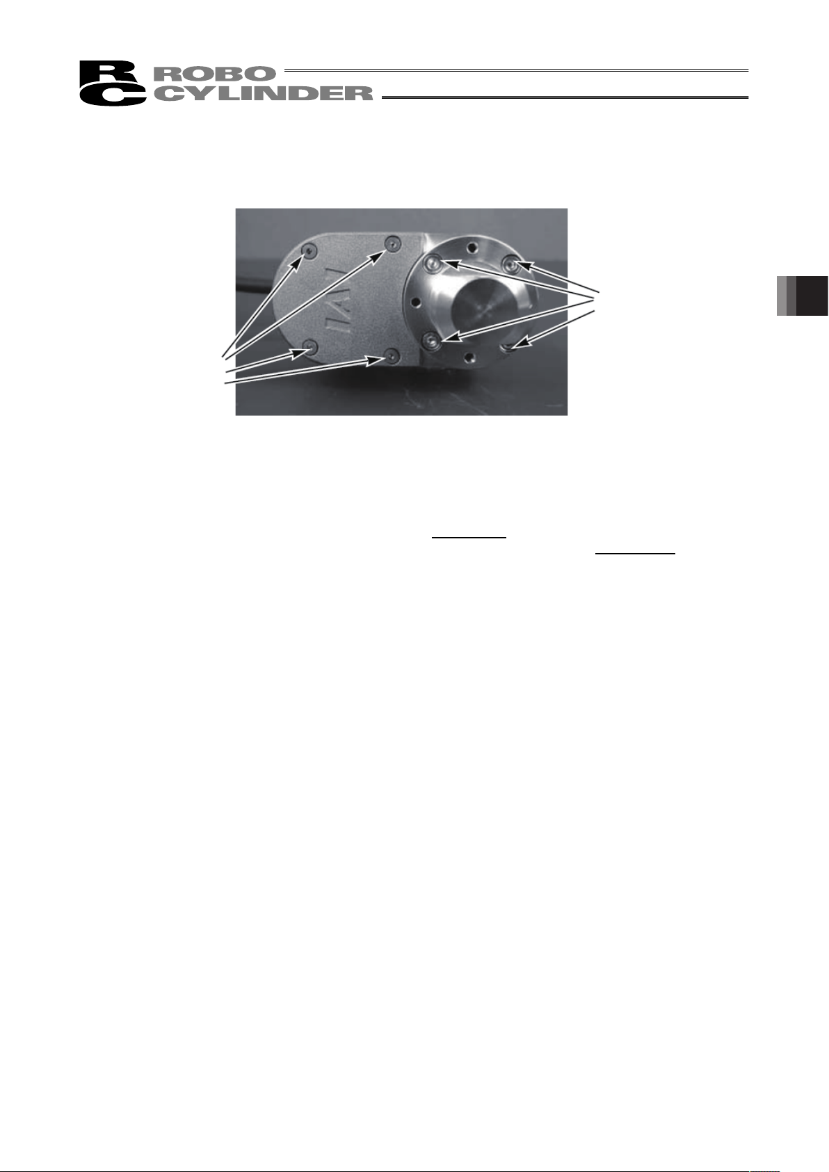
67
6) Install the pulley case cover using two Allen wrenches, one of 2 mm across flats and the other of 3
mm across flats.
7) Connect a PC or teaching pendant to the controller to perform homing. (If the actuator is of absolute
encoder specification, an absolute reset must be performed.) Check for deviation from the initial
home position.
If there is a deviation, adjust parameter No. 22, “Home offset
” if you are using an ACON controller.
If you are using an ASEL controller, adjust axis-specific parameter No. 12, “Home preset
.” If your
controller is of absolute encoder specification, perform homing after changing the parameter, and
then perform an absolute reset.
M3 hexagon socket
head screws
M4 hexagon socket
head screws
4. Maintenance
Page 74

4. Maintenance
68
4.6 Replacing the Motor
4.6.1 Replacing the Motor of the Motor Straight Type (Coupling Type):
RA3C/RA4C Types
[Items Required for Replacement]
y Replacement motor unit y Coupling (with screws)
y Allen wrenches
y Scale y Oil-based marker pen
y Grease
Idemitsu Kosan Daphne Eponex Grease No.2
y PC or teaching pendant
[Overview of Replacement]
1) Move the rod to a position where Z phase turns on (home position) (2 mm from the mechanical end).
In this position, replace the motor.
2) Perform homing using a PC or teaching pendant and check for deviation from the initial home
position.
If there is a deviation, adjust the home offset
if you are using an ACON controller. If you are using an
ASEL controller, adjust the home preset.
Replacement motor unit
Coupling (with screws)
Home position
Z phase ON
position
Mechanical end
Approx. 2 mm
The countermark on the motor
aligns with this position.
Set by the home offset parameter (ACON) or home
preset parameter (ASEL). (The above value indicates
the factory setting.)
1 mm
Page 75

69
[Procedure]
1) Move the rod to a position where Z phase turns on (home position).
This corresponds to a position where the rod projects 2 mm from the mechanical end.
Apply countermarks in this position.
Warning: If the actuator is installed vertically, move it after turning on the controller power and
forcibly releasing the brake. At this time, beware of danger as the actuator may drop
suddenly.
Always provide a support to brace the actuator hand to prevent sudden drop, so as not to
pinch fingers or damage the load.
2) Using an Allen wench of 2 mm across flats, remove the two motor-unit affixing bolts on the right and
left.
Cause the rod to project 2 mm from the mechanical end.
Apply countermarks once the rod has
projected 2 mm from the mechanical end.
2 affixing bolts on the motor-end
cap (right and left) (hexagon
socket head setscrews)
4. Maintenance
Page 76

4. Maintenance
70
3) Pull out the motor unit.
Before pulling out the motor unit, apply a countermark on the cylinder tube at a position
corresponding to the tab on the motor unit, so that the motor unit and cylinder can be aligned in the
correct position later on.
4) Apply grease on the actuator coupling.
Tab on the motor unit
Apply a countermark at a
position corresponding to
the tab on the motor unit.
Apply grease on the
inside of the coupling.
Page 77

71
5) Align the tab on the replacement motor unit with the countermark on the cylinder.
With the motor unit and cylinder aligned properly, insert the coupling into the replacement motor unit
by aligning the orientation of this coupling with that of the actuator coupling (adjusted to a position
corresponding to a rod projection of 2 mm from the mechanical end). Apply countermarks to identify
the current motor position (phase Z position) and coupling.
Align the tab on the
replacement motor unit
with the countermark on
the cylinder.
Position the couplings.
Coupling
Replacement
motor unit
After the coupling has been
inserted, apply countermarks
on the replacement motor
unit and coupling.
4. Maintenance
Page 78

4. Maintenance
72
6) Turn the coupling and motor shaft simultaneously until a setscrew on the coupling is seen through
the hole.
Thereafter, tighten the hexagon socket head setscrew using an Allen wrench of 2 mm across flats.
Similarly, turn the coupling and motor shaft simultaneously until the other screw is seen through the
hole, and tighten the setscrew.
Coupling
setscrew hole
Turn the coupling and motor shaft
simultaneously until a setscrew on the
coupling is seen through the hole.
Thereafter, tighten the hexagon socket
head setscrew using an Allen wrench of
2 mm across flats.
Page 79

73
7) Return the coupling in the replacement motor unit to the initial motor position (Z phase position).
Align the tab on the replacement motor unit with the countermark on the cylinder. With the motor unit
and cylinder positioned this way, confirm that the orientation of the actuator coupling (adjusted to a
position corresponding to a rod projection of 2 mm from the mechanical end) corresponds to the
position of the coupling in the replacement motor unit.
Apply countermarks on
the replacement motor
unit and coupling.
Coupling
Replacement
motor unit
Align the tab on the
replacement motor unit
with the countermark on
the cylinder.
Confirm that the coupling
positions correspond.
4. Maintenance
Page 80
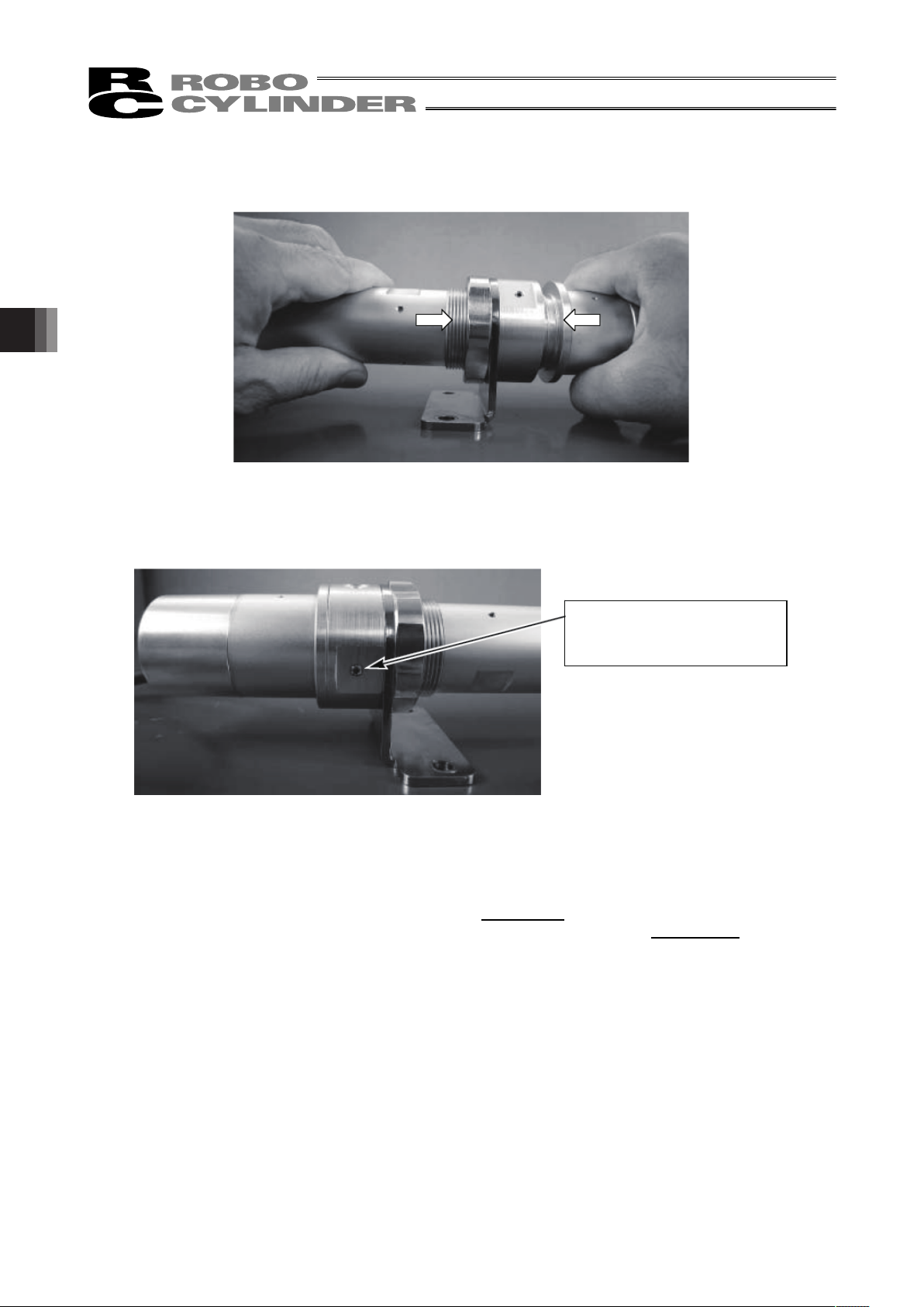
4. Maintenance
74
8) Carefully insert the replacement motor unit into the cylinder by ensuring that the couplings do not
lose their alignment.
9) Using an Allen wench of 2 mm across flats, tighten the two motor-unit affixing bolts on the right and
left.
10) Connect a PC or teaching pendant to the controller to perform homing. (If the actuator is of absolute
encoder specification, an absolute reset must be performed). Check for deviation from the initial
home position.
If there is a deviation, adjust parameter No. 22, “Home offset
” if you are using an ACON controller. If
you are using an ASEL controller, adjust axis-specific parameter No. 12, “Home preset
.” If your
controller is of absolute encoder specification, perform homing after changing the parameter, and
then perform an absolute reset.
2 affixing bolts on the motor-end
cap (right and left) (hexagon
socket head setscrews)
Page 81

75
4.6.2 Replacing the Motor of the Motor Reversing Type: RA3R/RA4R Types
[Items Required for Replacement]
y Replacement motor unit y Allen wrenches
y Tension gauge (capable of tensioning to 7 kgf or greater)
y Strong string, looped (or long tie-band)
y Scale y Oil-based marker pen
y PC or teaching pendant
[Overview of Replacement]
1) Loosen the motor-unit affixing bolts to remove the belt, and replace the motor.
2) Restore the home position.
Affix the rod at a position 2 mm from the mechanical end on the home side, pass the belt, and adjust
the belt to the specified tension.
3) Perform homing using a PC or teaching pendant and check for deviation from the initial home
position.
If there is a deviation, adjust the home offset
if you are using an ACON controller. If you are using an
ASEL controller, adjust the home preset
.
Replacement motor unit
Z phase ON
position
Mechanical end
Home position
Approx. 2 mm
The countermark on the motor
aligns with this position.
Set by the home offset parameter (ACON) or home preset
parameter (ASEL). (The above value indicates the factory setting.)
1 mm
4. Maintenance
Page 82
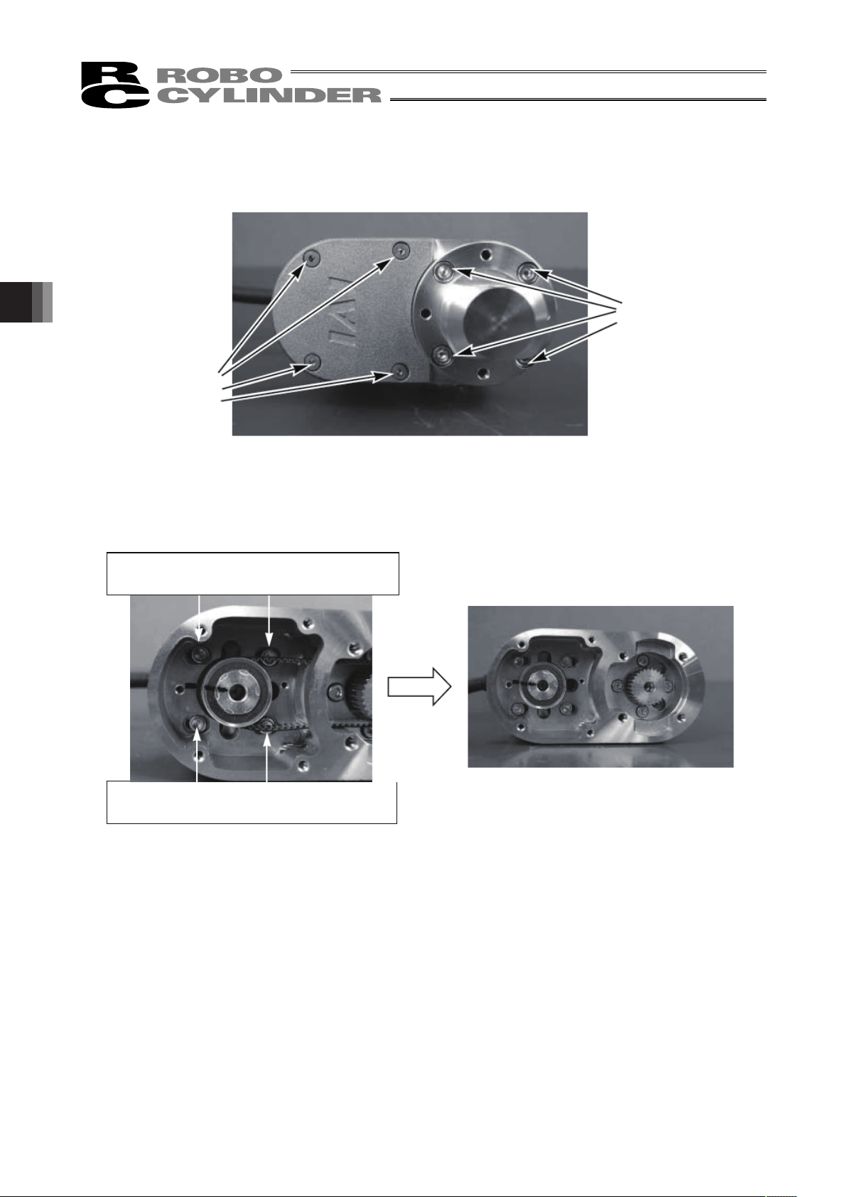
4. Maintenance
76
[Procedure]
1) Remove the pulley case cover using two Allen wrenches, one of 2 mm across flats and the other of 3
mm across flats.
2) Loosen the motor-unit affixing bolts using an Allen wrench of 2.5 mm across flats. Slide the motor,
and loosen and remove the belt. After the belt has been removed, remove the motor-unit affixing
bolts.
M3 hexagon socket
head screws
M4 hexagon socket
head screws
Motor-unit affixing bolts
(Use an Allen wrench of 2.5 mm across flats.)
Motor-unit affixing bolts
(Use an Allen wrench of 2.5 mm across flats.)
Page 83

77
3) Take out the motor.
4) Install the replacement motor. Loosely tighten the motor-unit affixing bolts.
Replacement motor
4. Maintenance
Page 84
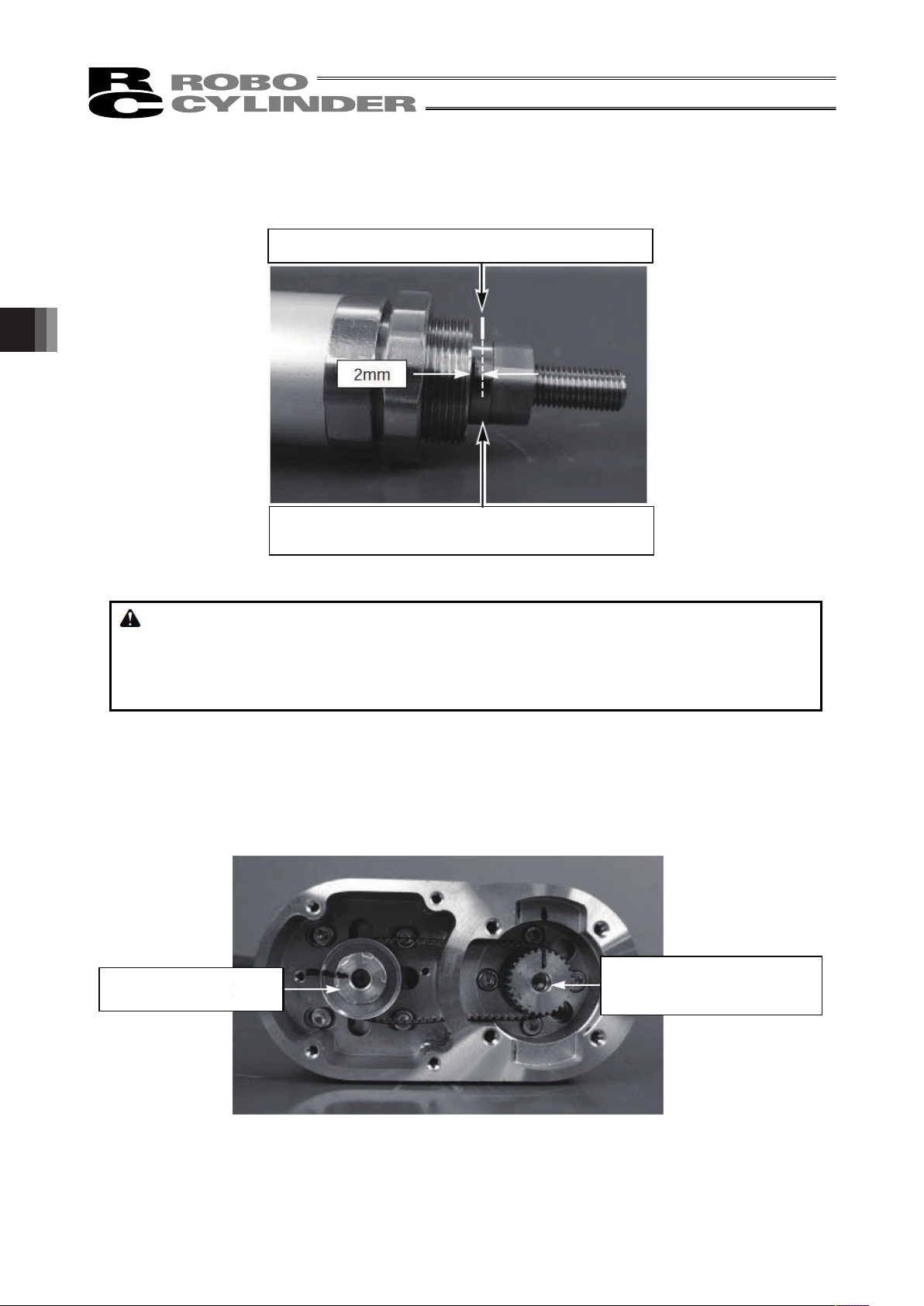
4. Maintenance
78
5) Move the rod to a position where Z phase turns on (home position).
This corresponds to a position where the rod projects 2 mm from the mechanical end.
Apply countermarks in this position.
Warning: If the actuator is installed vertically, move it after turning on the controller power and
forcibly releasing the brake. At this time, beware of danger as the actuator may drop
suddenly.
Always provide a support to brace the actuator hand to prevent sudden drop, so as not to
pinch fingers or damage the load.
6) Check the following points before restoring the home position:
y The motor side should be aligned with the initial countermark. If the position is offset, adjust it to
achieve proper alignment.
y The ball-screw side should be at a position where the rod projects 2 mm from the mechanical
end.
After the check, attach a new belt while holding the pulleys on both sides in position.
Cause the rod to project 2 mm from the mechanical end.
Apply countermarks once the rod has
projected 2 mm from the mechanical end.
Initial countermark position
Corresponding to a position where
the rod projects 2 mm from the
mechanical end
Motor side Ball-screw side
Page 85
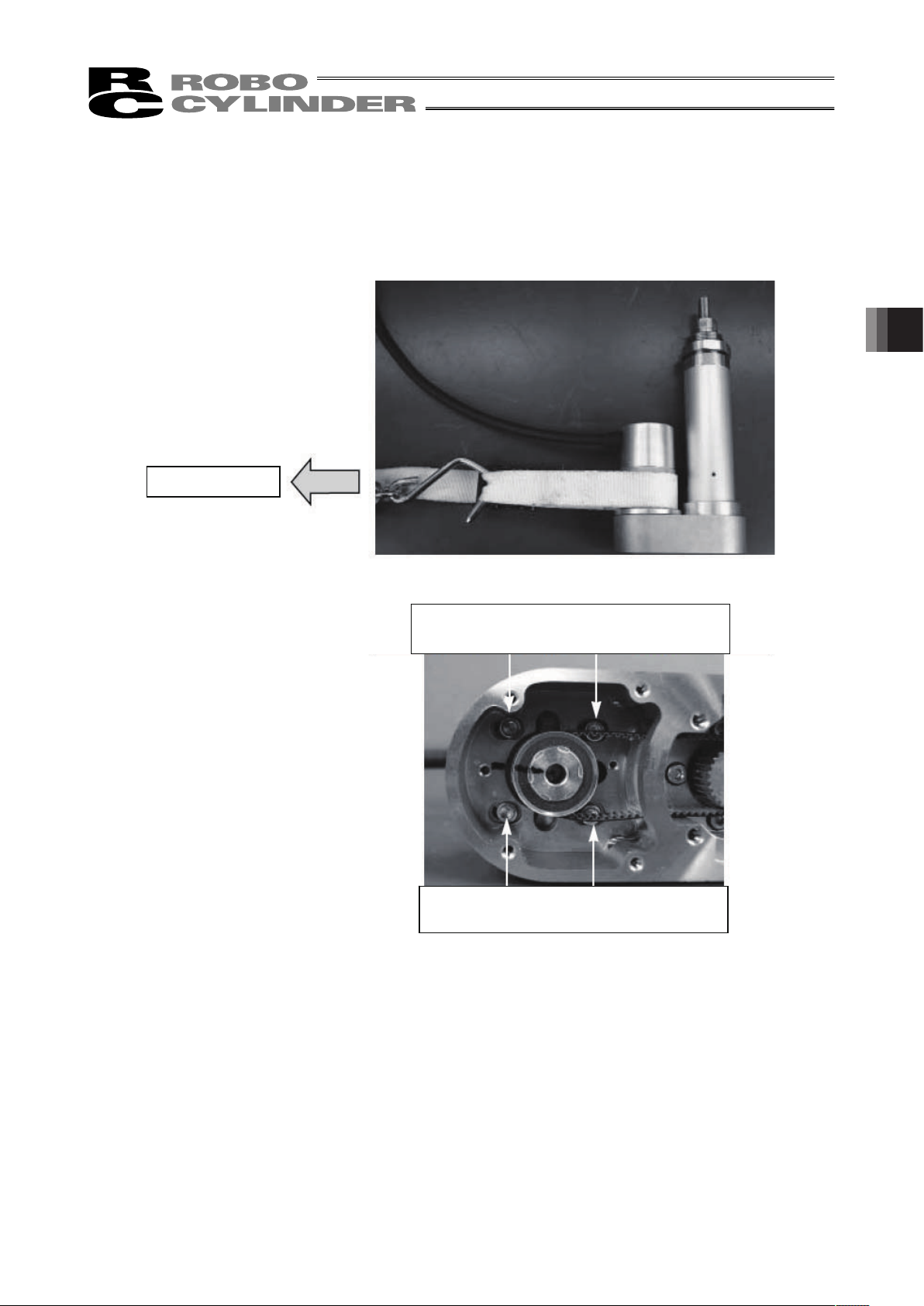
79
7) Adjust the belt tension.
Pass a looped strong string (or long tie-band) around the motor cover and pull it with a tension gauge
to the specified tension. In this condition, uniformly tighten the motor-unit affixing bolts.
[Recommended tightening torque for adjustment bolts]
162 N•cm (16.5 kgf•cm)
Tension: 2.5 kgf
Motor-unit affixing bolts
(Use an Allen wrench of 2.5 mm across flats.)
Motor-unit affixing bolts
(Use an Allen wrench of 2.5 mm across flats.)
4. Maintenance
Page 86

4. Maintenance
80
8) Remove the pulley case cover using two Allen wrenches, one of 2 mm across flats and the other of 3
mm across flats.
9) Connect a PC or teaching pendant to the controller to perform homing. (If the actuator is of absolute
encoder specification, an absolute reset must be performed.) Check for deviation from the initial
home position.
If there is a deviation, adjust parameter No. 22, “Home offset
” if you are using an ACON controller. If
you are using an ASEL controller, adjust axis-specific parameter No. 12, “Home preset
.” If your
controller is of absolute encoder specification, perform homing after changing the parameter, and
then perform an absolute reset.
M3 hexagon socket
head screws
M4 hexagon socket
head screws
Page 87
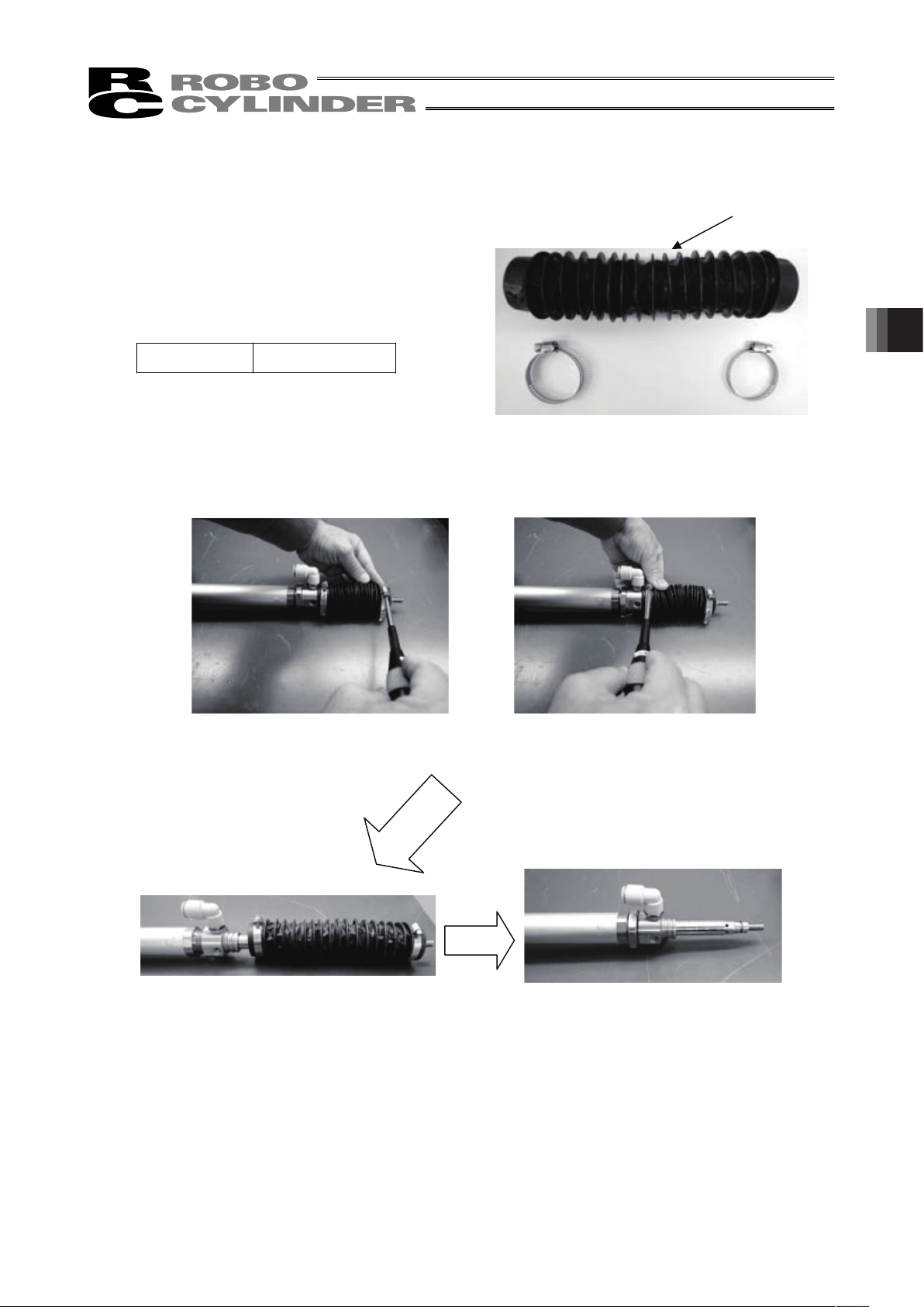
81
4.7 Replacing the Bellows of the RCAW Dustproof/Splash-proof Type
[Items Required for Replacement]
y Replacement bellows unit
: RA3 ······ JB-RA3- (stroke)
: RA4 ······ JB-RA4- (stroke)
y Phillips screwdriver
y Torque driver
y Grease
Kyodo Yushi Multemp LRL3
[Procedure]
1) Loosen the front and rear metal fittings affixing the bellows and remove the bellows.
Bellows
Loosening of front metal fitting Loosening of rear metal fitting
Removal of bellows Bellows has been removed
4. Maintenance
Page 88
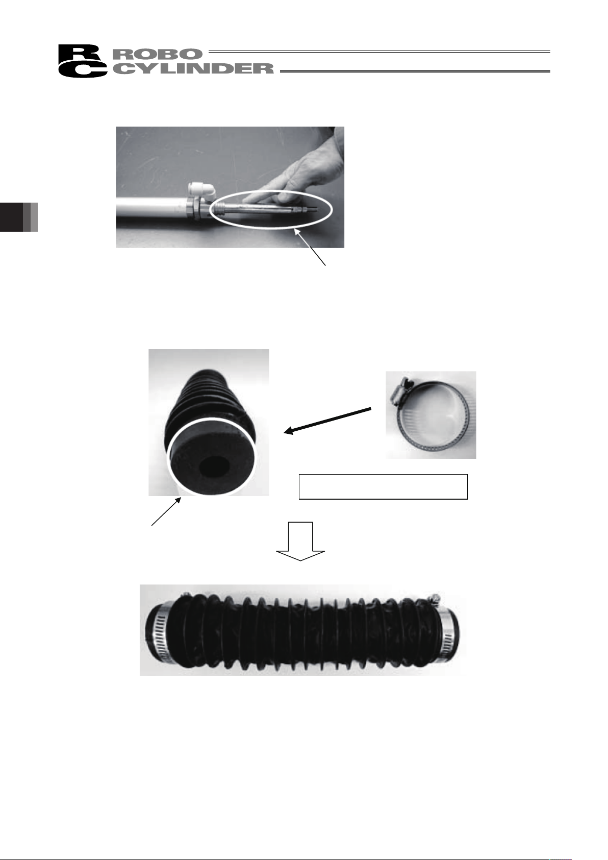
4. Maintenance
82
2) Apply grease evenly over the entire cylinder surface.
3) Install a metal fitting on the bellows.
Apply grease evenly over the entire
surface.
Bellows
Install a metal fitting on the bellows.
Page 89

83
4) Install the replacement (new) bellows and tighten the screws of the front and rear metal fittings
affixing the bellows. Tighten the screws to the specified torque using a torque driver.
Tightening torque: 2 N-m
Tightening torque: 2 N-m
Installation of bellows
Tightening of rear metal fitting Tightening of front metal fitting
4. Maintenance
Page 90

5. Appendix
84
5. Appendix
5.1 RCA-RA3C
ME: Mechanical End SE: Stroke End
5
48.6
34
M26 × 1.5
M35 × 1.5
M8 × 1.25
(15.01)
13
468
7 32
48.6
48.6
20
18
18
M8 × 1.25
(Effective screw range 16)
M26 × 1.5
(Effective screw range 15.5)
16 (Rod diameters)
14 (Width across Flats)
8 10 14
40 (Width across Flats)
32 (Width across Flats)
L
35
42
Secure at least 100
32
85.517
Nut B
Nut A
Nut C
ME
Home
SE
ME
3 3
st
49
8 10 14
40 (Width across Flats)
L
32
17
Nut B
SE
ME
3 3
st
49
43
( 35)
( 42)
124.5
[With Brake Type]
[Without Brake Type]
Cable Joint
Connector
50 100 150 200
L
322.5
132
0.9
372.5
182
1.0
422.5
232
1.1
472.5
282
1.2
RCA-RA3C (With brake)
50 100 150 200
L
283.5
132
0.7
333.5
182
0.8
383.5
232
0.9
433.5
282
1.0
RCA-RA3C (Without brake)
16 (Rod diameters)
14 (Width across Flats)
32 (Width across Flats)
Nut A
Nut C
ME
Home
Nut A Dimensions Nut B Dimensions Nut C Dimensions
Stroke
Stroke
Weight [kg]
Weight [kg]
M35 × 1.5
(Effective screw range 17.5)
from the directions other than the rod
operating directions.
The force in the vertical or rotational direction
of the rod may damage the stopper.
Caution
Page 91

85
5.2 RCA-RA4C
ME: Mechanical End SE: Stroke End
[With Brake Type]
[Without Brake Type]
6
(19.6)
17
52.8
40.2
50
38
M10 × 1.25
8
M40 × 1.5
M30 × 1.5
10
52.8
22
22
20
52.8
L
m
50
Incremental Type 42
Absolute Type 48
37
47 (Width across Flats)
3
st
3
16109
56 19
Nut B
ME
Home
ME
SE
L
m
47
37
3
st
3
16
109
56 19
Nut B
ME
SE
Nut A Nut B
Nut C
Secure at least 100
Cable Joint
Connector
50 100 150 200 250 300
L
20W
30W
279.5
292.5
294.5
307.5
137
1.1
379.5
392.5
394.5
407.5
237
1.4
479.5
492.5
494.5
507.5
337
1.7
329.5
342.5
344.5
357.5
187
1.2
429.5
442.5
444.5
457.5
287
1.5
529.5
542.5
544.5
557.5
387
1.8
67.5
80.5
82.5
95.5
m
20W
30W
RCA-RA4C (Without brake)
50 100 150 200 250 300
L
20W
30W
322.5
335.5
337.5
350.5
137
1.3
422.5
435.5
437.5
450.5
237
1.6
522.5
535.5
537.5
550.5
337
1.9
372.5
385.5
387.5
400.5
187
1.4
472.5
485.5
487.5
500.5
287
1.7
572.5
585.5
587.5
600.5
387
2.0
110.5
123.5
125.5
138.5
m
20W
30W
RCA-RA4C (With brake)
M10 × 1.25
(Effective screw range 20)
M30 × 1.5
(Effective screw range 17.5)
M40 × 1.5
(Effective screw range 19.5)
20 (Rod diameters)
36 (Width across Flats)
Nut A
19 (Width across Flats)
Nut C
( 50)
Incremental Type 42
Absolute Type 48
47 (Width across Flats)
ME
Home
20 (Rod diameters)
36 (Width across Flats)
Nut A
19 (Width
across Flats)
Nut C
Stroke
Weight [kg]
Incremental
Absolute
Incremental
Absolute
Incremental
Absolute
Incremental
Absolute
Stroke
Weight [kg]
Incremental
Absolute
Incremental
Absolute
Incremental
Absolute
Incremental
Absolute
from the directions other than the rod
operating directions.
The force in the vertical or rotational direction
of the rod may damage the stopper.
Caution
5. Appendix
Page 92

5. Appendix
86
5.3 RCA-RA3D
ME: Mechanical End SE: Stroke End
RCA-RA3D type is no
breake-equipped type.
L
66.5
48.6
48.6
8 10
14
40 (Width
across Flats
35
42
32
17
20
18
Nut B
Nut A
5
(15.01)
13
468
7 32
18
Nut C
SE
ME
3 3
st
49
Secure at least 100
Cable Joint
Connector
50 100 150 200
L
264.5
132
0.7
314.5
182
0.8
364.5
232
0.9
414.5
282
1.0
RCA-RA3D (Without brake)
M8 × 1.25
M26 × 1.5
M35 × 1.5
14 (Width across Flats)
32 (Width across Flats)
ME
34
M26 × 1.5
48.6
M35 × 1.5
M8 × 1.25
Stroke
Caution
Page 93

87
5.4 RCA-RA4D
ME: Mechanical End SE: Stroke End
RCA-RA4D type is no
breake-equipped type.
50
20 (Rod diameters)
L
m
6
37
52.8
52.8
47 (Width across Flats)
36 (Width across Flats)
19 (Width across Flats)
3
st
3
16109
56 19
22
22
20
(19.6)
17
50
388
M40 × 1.5
M30 × 1.5
10
Nut A
Nut C
Nut B
ME
Home
ME
SE
Nut A Nut B
Nut C
Secure at least 100
Cable Joint
Connector
50 100 150 200 250 300
L
257.5
270.5
272.5
285.5
137
1.0
357.5
370.5
372.5
385.5
237
1.3
457.5
470.5
472.5
485.5
337
1.6
307.5
320.5
322.5
335.5
187
1.2
407.5
420.5
422.5
435.5
287
1.5
507.5
520.5
522.5
535.5
387
1.8
45.5
58.5
60.5
73.5
m
RCA-RA4D
M10 × 1.25
M30 × 1.5
M40 × 1.5
42
48
52.8
40.2
M10 × 1.25
Incremental
Absolute
Incremental
Absolute
Incremental
Absolute
Incremental
Absolute
Caution
5. Appendix
Page 94

5. Appendix
88
5.5 RCA-RA3R
ME: Mechanical End SE: Stroke End
42
14 (Width across Flats)
3 3
181818
84.4
42.4
84.4
42.4
31
L
st 49
8 10
P
2585.5
32
35
(15.01)
135
7
32
Nut A
Nut B
ME
Home
ME
SE
3 3
31st
L
49
8 10
P
25124.5
43
Nut A
ME
SE
Cable Joint
Connector
50 10 0 150 200
L
P
218
120
1.0
268
170
1.1
155.5
318
220
1.2
368
270
1.3
RCA-RA3R (With brake)
50 10 0 150 200
L
P
218
120
0.8
268
170
0.9
116.5
318
220
1.0
368
270
1.1
RCA-RA3R (Without brake)
[Without Brake Type]
[With Brake Type]
M8 × 1.25
(Effective screw range 16)
M26 × 1.5
(Effective screw range 15. 5)
M26 × 1.5
(Effective screw range 15. 5)
16 (Rod diameters)
32 (Width across Flats)
Nut A
Secure at least 100
M8, depth 15
14 (Width across Flats)
Nut B
32 (Width across Flats)
Nut A
16 (Rod diameters)
ME
Home
42
35
32
Nut A Dimensions Nut B Dimensions
M26 × 1.5
M8 × 1.25
34
Stroke
Stroke
Weight [kg]
Weight [kg]
Do not apply any external force to the rod
from the directions other than the rod
operating directions.
The force in the vertical or rotational direction
of the rod may damage the stopper.
Caution
Page 95

89
5.6 RCA-RA4R
ME: Mechanical End SE: Stroke End
37
48
50
P
m
50.5
98.5
50.5
98.5
3 3
L
3356
9 10
26
20
20
22
(19.6)
17
388
6
Nut A
st
SE
ME
Nut B
Nut A
37
50
P
m
3 3
L
3356
9 10
26
47
Nut A
st
SE
ME
Nut A
Cable Joint
Connector
50 100 150 200 250 300
L
234
234
234
234
125
1.2
334
334
334
334
225
1.5
434
434
434
434
325
1.8
284
284
284
284
175
1.4
384
384
384
384
275
1.7
484
484
484
484
375
2.0
67.5
80.5
82.5
95.5
100.5
113.5
115.5
128.5
m
P
RCA-RA4R
50 100 150 200 250 300
L
234
234
234
234
125
1.4
334
334
334
334
225
1.7
434
434
434
434
325
2.0
284
284
284
284
175
1.6
384
384
384
384
275
1.9
484
484
484
484
375
2.2
110.5
123.5
125.5
138.5
143.5
156.5
158.5
171.5
m
P
RCA-RA4R
M10 × 1.25
M30 × 1.5
Nut A
Nut B
40.2
M10 × 1.25
M30 × 1.5
M10 × 1.25
42
48
36 (between
2 flat faces)
Secure at least 100
19 (Width across Flats)
ME
Home
ME
Home
Nut B
19 (Width across Flats)
36 (Width across Flats)
42
48
M10 × 1.25,
Incremental
Absolute
Incremental
Absolute
Incremental
Absolute
Incremental
Absolute
Incremental
Absolute
Incremental
Absolute
Incremental
Absolute
Incremental
Absolute
Incremental
Absolute
Incremental
Absolute
Incremental
Absolute
Incremental
Absolute
Caution
5. Appendix
Page 96
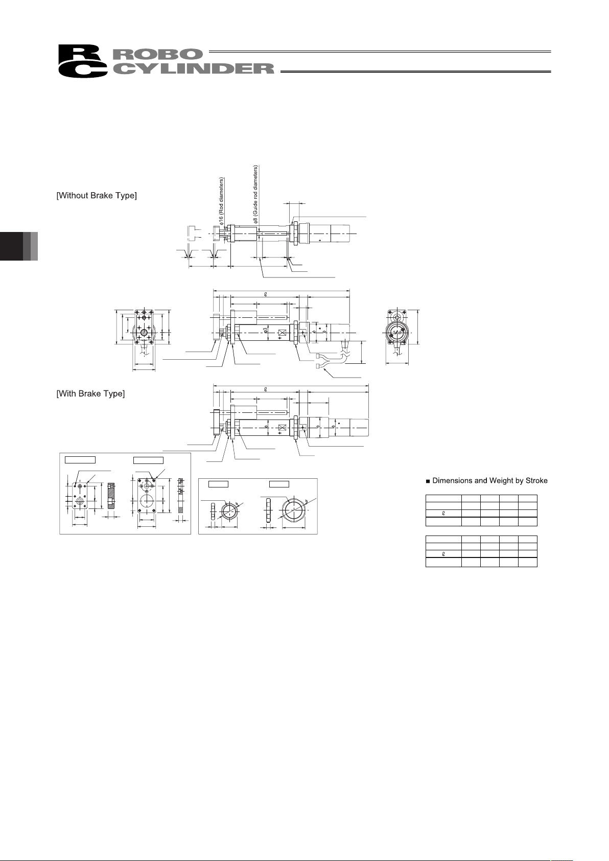
5. Appendix
90
5.7 RCA-RGS3C
ME: Mechanical End SE: Stroke End
4624
15 37.5
70
52.5
30.5
14
4-C2
8 85.517
L
5(st + 12)53
Shaft overhang at SE position
ME
Home
(st + 65)
12 st 3
35st
33
20
4-M5
8
41.5
19.5
70
24
15
30.5
37
29
Bracket B
Bracket A
12
4-C2
10 20.5
10
52.5
30.5
30
20
37
70
46
46
6-M4 through
32 (Width across
Flats)
35
42
2
Nut B
Nut A
ME
Home
ME
SE
8 46
32
48.6
7
14 43
8
124.5
17
L
5(st+12)
53
35
42
32
Secure at
least 100
Bracket B
Bracket A
Cable Joint
Connector
50 100 150 200
L
316.5
140
1.1
366.5
190
1.3
416.5
240
1.4
466.5
290
1.5
RCA-RGS3C (With brake)
Stroke 50 100 150 200
L
Weight [kg]
277.5
140
0.9
327.5
190
1.1
377.5
240
1.2
427.5
290
1.3
RCA-RGS3C (Without brake)
M35 × 1.5
(Effective screw range 17.5)
40 (Width
across Flats)
14 (Width across Flats)
40 (Width across Flats)
Bracket B
Bracket A
32 (Width
across Flats)
Nut B
Nut A
14 (Width across Flats)
34
M35 × 1.5
M26 × 1.5
Nut A
Nut B
Stroke
Weight [kg]
Page 97
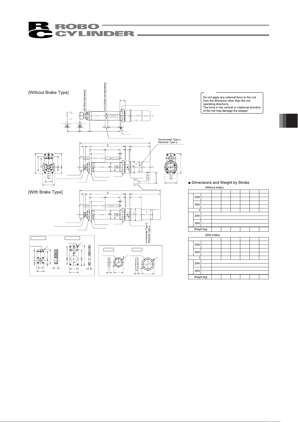
91
5.8 RCA-RGS4C
ME: Mechanical End SE: Stroke End
55
44
26
15
81
59
36.5
50
50
81
Bracket A
Bracket B
16
9
37
L
m19
1
(st + 11)
63
50
30
(st + 74)
Home
Shaft overhang at SE position
ME
3st11
41
ME
Home
ME
SE
33
st
22
52.8
50
388
10
4-M5
4-C2
8
81
36.526
5022
37
29
15
59
15 36.5
4-C2
30
20
10 10 26.5
Secure at
least 100
( 50)
16 47
9
37
L
m19
1
(st + 11)
63
Cable Joint
Connector
50
100 150 200 250 300
L
272.5
285.5
287.5
300.5
145
1.5
372.5
385.5
387.5
400.5
245
1.8
472.5
485.5
487.5
500.5
345
2.2
322.5
335.5
337.5
350.5
195
1.6
422.5
435.5
437.5
450.5
295
2.0
522.5
535.5
537.5
550.5
395
2.4
67.5
80.5
82.5
95.5
m
RCA-RGS4C
50 100 150 200 250 300
L
315.5
328.5
330.5
343.5
145
1.7
415.5
428.5
430.5
443.5
245
2.0
515.5
528.5
530.5
543.5
345
2.4
365.5
378.5
380.5
393.5
195
1.8
465.5
478.5
480.5
493.5
295
2.2
565.5
578.5
580.5
593.5
395
2.6
110.5
123.5
125.5
138.5
m
RCA-RGS4C
Caution
M40 × 1.5
(Effective screw range 19.5)
42
48
Nut A
Nut B
36 (Width
across Flats)
19 (Width across Flats)
47 (Width
across Flats)
42
48
47 (Width
across Flats)
Bracket A
Bracket B
Nut A
Nut B
36 (Width
across Flats)
19 (Width across Flats)
6-M4 through
Bracket B
Bracket A
40.2
M40 × 1.5
M30 × 1.5
Nut A
Nut B
Stroke
Incremental
Absolute
Incremental
Absolute
Incremental
Absolute
Incremental
Absolute
Stroke
Incremental
Absolute
Incremental
Absolute
Incremental
Absolute
Incremental
Absolute
5. Appendix
Page 98

5. Appendix
92
5.9 RCA-RGS3D
ME: Mechanical End SE: Stroke End
RCA-RGS3D type is no
breake-equipped type.
35
42
4624
15 37.5
70
52.5
30.5
14
8 66.517
L
5(st + 12)53
Shaft overhang at SE position
(st + 65)
12 st 3
35st
33
20
37
70
46
46
2
ME
SE
4-C2
4-M5
8
41.519.5
70
24
15
30.5
37
29
12
4-C2
10 20.510
52.5
30.5
30
20
8 46
327
50 100 150 200
L
258.5
140
0.9
308.5
190
1.1
358.5
240
1.2
408.5
290
1.3
RCA-RGS3D (Without brake)
M35 × 1.5
(Effective screw range 17.5)
ME
ME
Bracket B
Bracket A
32 (Width across Flats)
Nut B
Nut A
Secure at
least 100
Cable Joint
Connector
40 (Width
across Flats)
14 (Width across Flats)
6-M4 through
Bracket B
Bracket A
48.6
34
M35 × 1.5
M26 × 1.5
Nut A
Nut B
Stroke
Page 99
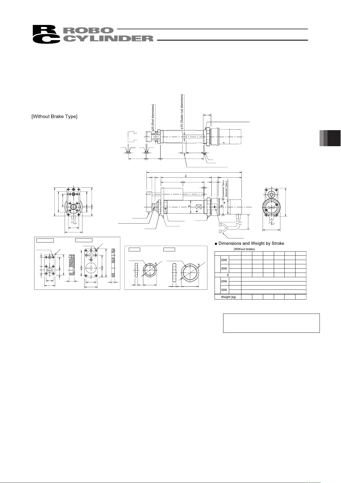
93
5.10 RCA-RGS4D
ME: Mechanical End SE: Stroke End
RCA-RGS4D type is no
breake-equipped type.
(st + 74)
Shaft overhang at SE position
3st11
41
ME
SE
33
st
22
4-M5
4-C2
8
81
36.526
5022
37
29
15
59
15 36.5
4-C2
30
20
10 10 26.5
55
44
26
15
81
59
36.5
50
30
50
388
10
50
81
L
50
Bracket A
16
9
19 (Width across Flats)
Nut A
Nut B
37
19
1
(st + 11)63
m
Cable Joint
Connector
50 100 150 200 250 300
L
250.5
263.5
265.5
278.5
145
1.3
350.5
363.5
365.5
378.5
245
1.7
450.5
463.5
465.5
478.5
345
2.1
300.5
313.5
315.5
328.5
195
1.5
400.5
413.5
415.5
428.5
295
1.9
500.5
513.5
515.5
528.5
395
2.3
45.5
58.5
60.5
73.5
m
RCA-RGS4D
M40 × 1.5
(Effective screw range 19.5)
ME
Home
ME
Home
42
48
Bracket B
36 (Width
across Flats)
Secure at
least 100
47 (Width
across Flats)
6-M5 through
Bracket B
Bracket A
52.8
40.2
M40 × 1.5
M30 × 1.5
Nut A
Nut B
Stroke
Incremental
Absolute
Incremental
Absolute
Incremental
Absolute
Incremental
Absolute
5. Appendix
Page 100

5. Appendix
94
5.11 RCA-RGD3C
ME: Mechanical End SE: Stroke End
4-C2
4-M5
(through)
8
92
83
37
29
12
4-C2
75
30
20
20.5
20.5
20
8
46
32
7
Bracket A Bracket B
Nut A Nut B
928375
61
29
20
48.6
37
30
14
8
92
48.6
32
85.517
L
5
(st + 12)53
(st + 65)
12 st 3
35st
33
20
35
42
Nut B
ME
Home
ME
SE
14
8
32
17
124.5
L
5
(st + 12)
53
43
( 35)
(
42)
50 100 150 200
L
316.5
140
1.3
366.5
190
1.4
416.5
240
1.6
466.5
290
1.7
RCA-RGD3C (With brake)
50 100 150 200
L
277.5
140
1.1
327.5
190
1.2
377.5
240
1.4
427.5
290
1.5
RCA-RGD3C (Without brake)
M35 × 1.5
ME
Home
Secure at
least 100
Bracket B
Bracket A
Nut A
32(Width
across Flats)
Bracket B
Bracket A
Nut A
8-M4
(through)
M35 × 1.5
M26 × 1.5
48.6
34
Stroke
Stroke
(Width across Flats)
(Width across Flats)
32(Width
across Flats)
40(Width
across Flats)
 Loading...