

Page 1

Robo Cylinder Data Input Pendant
RCA-P
Operating Manual
Ver. 4.0
IAI Corporation
Page 2

Page 3

Table of Contents
1. Foreword.................................................................................................................................................... 1
2. Before You Begin....................................................................................................................................... 1
3. Safety Precautions..................................................................................................................................... 2
4. Warranty and Scope of Warranty............................................................................................................... 3
5. Application Environment ............................................................................................................................ 4
6. Functions and Specifications of Data Input Pendant.................................................................................. 5
6-1 Specifications...................................................................................................................................... 5
6-2 External View...................................................................................................................................... 6
6-3 Description of Each Part..................................................................................................................... 7
7. Connection With the Controller .................................................................................................................. 9
7-1 Connection with the Data Input Pendant............................................................................................. 9
7-2 How to Disengage the Data Input Pendant......................................................................................... 9
8. Operation.................................................................................................................................................10
8-1 Initial Screen During Power - UP ...................................................................................................... 12
8-2 Controller Selection (when using multiple units) ............................................................................... 13
8-3 Operation Mode Selection ................................................................................................................ 14
8-4 Edit/Teaching.................................................................................................................................... 15
8-4-1 Edit/Teach Screen..................................................................................................................... 15
8-4-2 Position Data Table ................................................................................................................... 16
8-4-3 Data Input..................................................................................................................................19
8-4-5 Add • Delete............................................................................................................................... 24
8-4-5 Data Modification....................................................................................................................... 29
8-5 Monitor.............................................................................................................................................. 30
8-6 Error List ........................................................................................................................................... 31
8-7 User Parameter................................................................................................................................. 32
8-8 User Adjustment ............................................................................................................................... 34
8-9 End ................................................................................................................................................... 35
9. Message Area.......................................................................................................................................... 36
9-1 Warning Label Error (Code No. 000h – 07Fh) .................................................................................. 36
9-2 Data Input Pendant Message Level Error......................................................................................... 37
9-3 Controller Error ................................................................................................................................. 37
Page 4

Page 5

1. Foreword
Thank you very much for purchasing the Data Input Pendant (RCA-P) for the Robo Cylinder Controller.
Without knowing beforehand how to correctly use or operate the Data Input Pendant, not only will the user be
unable to take full advantage of all the functions built into this product but the user might also inadvertently
cause damage to the Controller or shorten its life. Please read this manual carefully as well as other manuals
pertaining to the product to acquire an understanding of the proper method of handling and operating the
controller. Keep this manual handy so that you can refer to the appropriate sections as the need arises.
For the actuator and controller to be used, be sure to refer to the Instruction Manuals attached to the
products.
Caution: Do not edit position data while the actuator is operating by PLC, etc.
Also, do not edit any position number not actually operated.
2. Before You Begin
(1) Please read this manual carefully to operate the controller properly.
(2) You are not allowed to reproduce this manual or any portion thereof without permission.
(3) For any handling and operating methods other than those described in this Instruction Manual,
interpret them as “
(4) We cannot accept any responsibility for possible damage resulting from the use of this manual.
(5) We reserve the right to change the information contained in this manual without prior notice.
don’t” or “can’t.”
1
Page 6

3. Safety Precautions
(1) Use a genuine product specified by us for wiring between the actuator and controller.
(2) Stand clear of the operating range of the machine when it is in motion or is ready to operate. Surround
the system with safety partitions if there is a possibility that people can enter the area where the machine
is being used.
(3) When assembling, adjusting, or performing maintenance on the machine, always disengage the power
supply to the controller. During work, display a sign stating work in progress where it is readily visible.
Also, keep the power cable close to the operator so that another person cannot inadvertently switch on
the power. Alternatively, lock the power plug or receptacle and direct the operator to hold the key or
prepare a safety plug.
(4) When more than one person is working on the system, agree on signals beforehand to ensure
everyone's safety before beginning work. In particular, when doing work involving axis movement,
always call out for everyone's safety regardless of whether power is ON or OFF, or the axis is to be
mechanically driven or manually moved.
(5) When the user needs to lengthen the cables, check the wiring carefully to make sure it is correct before
turning the power ON since miswiring can lead to misoperation.
2
Page 7

4. Warranty and Scope of Warranty
The Data Input Pendant undergoes stringent testing before it is shipped from our factory.
IAI provides the following warranty.
1. Warranty Period
The warranty period shall be either the following period, whichever is reached first.
- 18 months after our shipment
- 12 months after delivery to the place designated by you
2. Scope of Warranty
If within the period specified above, a breakdown occurs while operating the controller under normal
conditions and is clearly the responsibility of the manufacturer, IAI will repair the unit at no cost. However,
the following items are not covered by this warranty.
- Faded paint or other changes that occur naturally over time.
- Consumable components that wear out (such as a cable).
- Unit seems to be noisy or similar impressions that do not affect machinery performance.
- Damage resulting from improper handling or use.
- Damage resulting from user error or failure to perform proper maintenance.
- Damage resulting from the use of any part other than our genuine parts.
- Any alterations not authorized by IAI or its representatives.
- Damage caused by fire and other natural disasters or accidents.
The warranty pertains to the purchased product itself and does not cover any loss that might arise from a
breakdown of the product. Any repairs will be done at our factory.
3. Service
The purchase price of the product does not include programming or expenses for sending technicians to
the customer's site. Even if the product is still under the warranty period, separate charges will be assessed
for the following services.
- Inspection and maintenance.
- Technical guidance and technical training in operating instructions.
- Technical guidance and technical training on program-related matters such as program creation.
3
Page 8

5. Application Environment
- In order to avoid breakdown, please do not apply any type of machinery impact onto the Data Input
Pendant.
- Always hold onto the entire Data Input Pendant Body so that the Data Inpu t Pendant Cable does not
get pulled by unwanted cables.
Caution: This Data Input Pendant is designed exclusively for the IAI RC
Controller, and should not be used to connect with other devices.
Caution: Regarding controller connection, please turn the controller front side port
switch OFF before connecting to the controller.
4
Page 9

6. Functions and Specifications of Data Input Pendant
Through the communication between the controller, the RC Data Input Pendant is designed to function
as the Display Operation Unit to edit or display the data (common data, move point data, etc.,) that is stored
inside the controller.
It cannot be used for any operation related to axis movement.
LCD: Horizontal 16 characters Vertical 2 lines
6-1 Specifications
Item Specification
Ambient Temperature & Humidity
Operating Environment Free of corrosive gas, especially, no excessive dust
Weight 380g
Cable Length 5m
Temperature: 0°~40°C Humidity: 85% RH or less
* RH relative humidity
5
Page 10
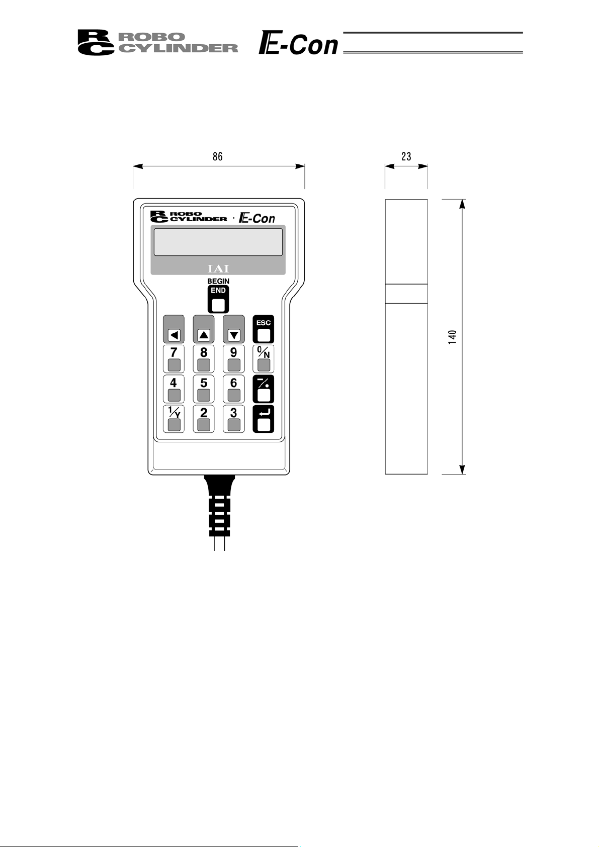
6-2 External View
External Dimensions
6
Page 11
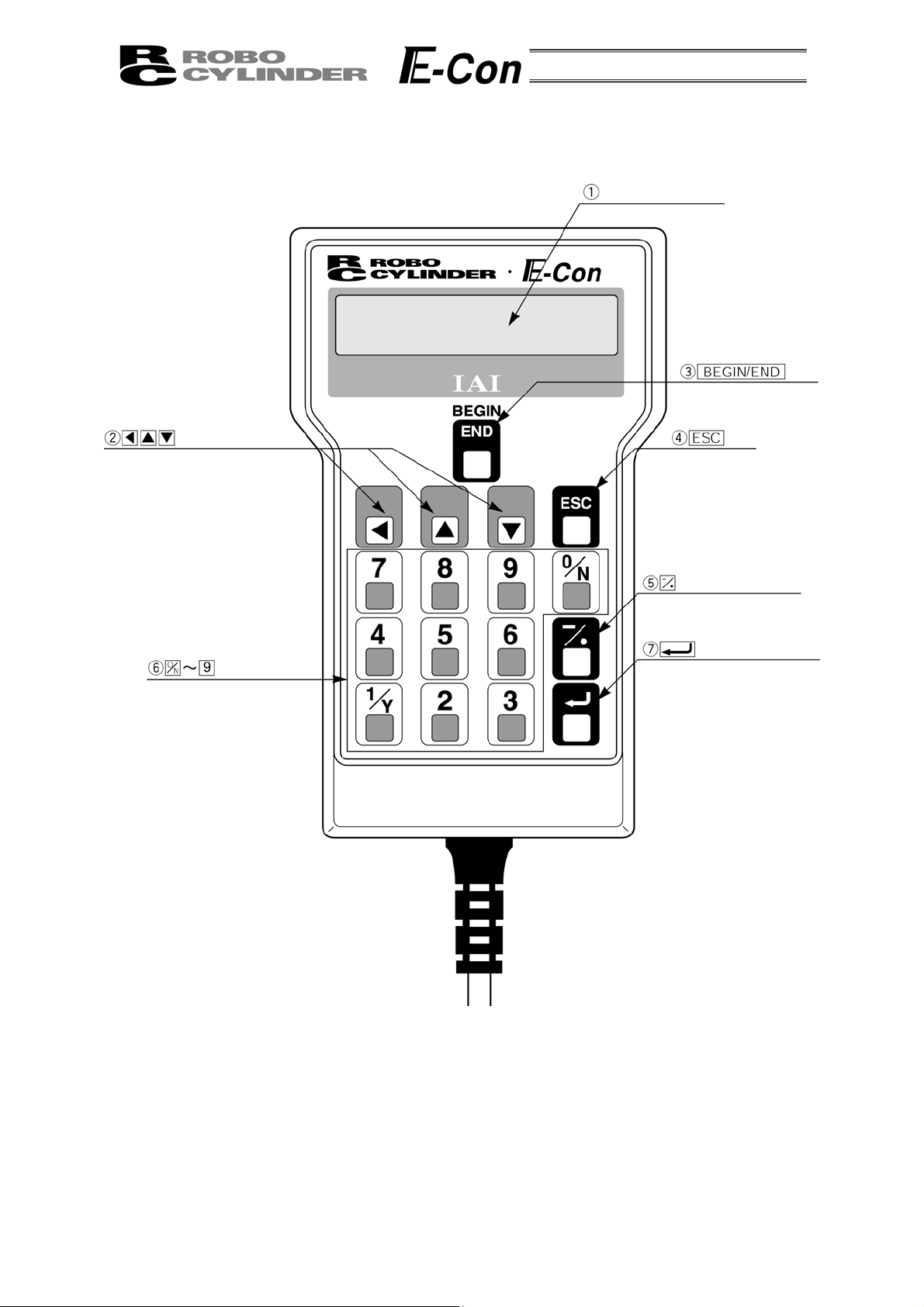
6-3 Description of Each Part
A
LCD Display
Key
rrow Keys
Numeric Key
Key
Minus Key
Return Key
7
Page 12

(1) LCD Display
This is a liquid crystal display with a maximum of horizontal: 16 characters per column, and vertical: 2
columns per row.
This displays edit and teaching contents of various set values.
(2)
Arrow Key
- This is used for selection of the mode, the contents of data and changing position No.
(3)
Key
- Execution of Data Input Pendant configuration or axis reconnection.
By pressing this key for more than 2.5 seconds, the screen will change into the “BEGIN/END” screen
and you will be able to reconnect the axis and execute Data Input Pendant configuration.
- If entering data via key pad, you may cancel midway using this key.
- You may clear error warning.
- When an error occurs, a message for this error will appear at the very bottom of the display screen.
Use this key to clear the error and to clear this message.
(4)
ESC
Key
- Return to the display of a previous screen
The Data Input Pendant operation has a several-layer nested structure. Using this key can return the
user to one layer above (previous screen).
When you don’t understand the operation, undo the operation by pressing the ESC Key.
(5)
(Minus) Key
- Position Table Column: When you push this in an area such as positioning width which allows minus
input, the key functions as the “-” (minus), and the rest as “.” (point). When you input either
in the beginning of the number, within the proper area, the key will automatically recognize it as 0.
(6)
(Numeric) Key
- This key is used for numeric input.
(7)
(Return) Key
- This is used for data input and operation confirm.
or
8
Page 13

7. Connection With the Controller
7-1 Connection with the Data Input Pendant
(1) Connect the Data Input Pendant Cable to the “PORT IN” connector which is located on the front of the
controller. Always turn OFF the controller Port Switch first before connecting.
(In a case of ERC, there is no Port Switch,
PORT switch
PORT IN connector
please power off the unit.)
(2) After connecting, turn the controller PORT Switch ON.
7-2 How to Disengage the Data Input Pendant
Hold down the BEGIN/END Key which is located in the upper of the key pad. Select “Complete” to
finish. Afterwards, turn the controller front SW side to OFF, and remove the Data input pendant
connector.
Operation:
1. Hold down the BEGIN/END Key for more than 2.5 seconds.
2. Use the Arrow Key to select “Complete” Screen, and then press the Return Key.
3. Turn the RC Controller PORT SW OFF.
4. Remove the Data Input Pendant connector.
9
Page 14

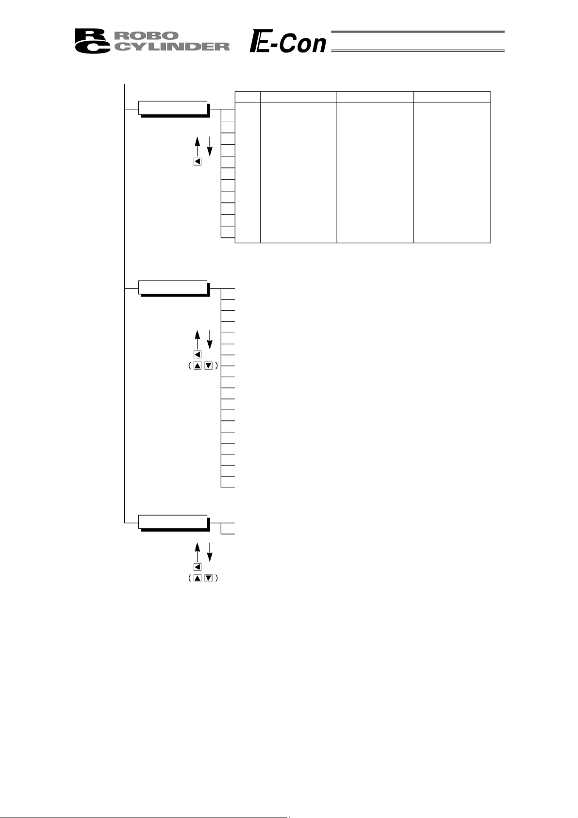
8. Operation
The Data Input Pendant operation has the following overall tree structure.
The menus in this tree structure differ according to the controller type/version or Data Input Pendant
version. For details, refer to the Instruction Manual of each controller. The following indicates the case of
ERC.
Power-ON
Reconnect
Axis Select
Confirming connection
Return Return
Mode Select
Operation
Start/End
End
* You will be able to change to the
“Operation Start/End” screen from
any other screen by using
BEGIN/END key.
Please, press BEGIN/END key for
more than 2.5 seconds.
Edit / Teach
Monitor
Return Return
(2) Add
(3) Delete
(4) Clear
(5) All Clear
(6) Direct Teach
*1: The menu descriptions are as
shown on the following page
according to the PIO pattern.
(1) Position
(2) Speed
(3) ACC • DEC
(4) Push Power
(5) Positioning
(6) Rated speed only MAX
(7) ABS / INC
Incorporate
10
*2
Error List
(1) Error No.
(2) Message
(3) Axis No.
(4) __Minutes ago occurrence
Page 15
*2 *1
Monitor
User Parameter
Return
Return
(1)
(2)
(3)
(4)
(5)
(6)
(7)
(8)
(9)
(10)
(11)
(12)
3 Position Type
Position
Error No.
Servo ON
in ST0
in ST1
in ST2
in_STP
out PE0
out PE1
out PE2
out_ALM
CTL Ver
(PIO:1)
8 Position Type
Position
Error No.
Servo ON
in START
in Position No.
in_STP
in_HOME
out PEND
out HEND
out ZONE
out_ALM
CTL Ver
(1) + Zone
(2) - Zone
(3) + Limit
(4) - Limit
(5) Home
(6) Reset speed
(7) Reset
ACC • DEC
(8) Reset range
MAX
(9) Acceleration
(10) Push stop determined
(11) Servo gain
(12) Current stop
(13) Home current
(14) Temporary stop not effect
(15) Baud rate
(16) PTIM
(17) Offset
(18) PIO pattern
(19) Move instruction type
(PIO:0)
16 Position Type
Position
Error No.
Servo ON
in START
in Position No.
in_STP
in_PEND
out HEND
out ZONE
out_ALM
CTL Ver
(PIO:2)
User Adjustment
(1) Adjustment No.
(2) Distribution No.
Return
11
Page 16

8-1 Initial Screen During Power - UP
When power is connected to the controller and the controller PORT switch is ON, power is supplied
to the Data Input Pendant and operation starts.
Upon power-on, the LCD display screen (hereinafter called the “screen”) displays the Data Input
Pendant software version as follows:
Confirming connection
IAI RC DU V.1.66
Once the controller connection has been completed, the screen automatically moves to the Mode
Select screen in a defined period of time.
12
Page 17

8-2 Controller Selection (when using multiple units)
A
In case of multiple units connected serially via the communication line, the axis selection screen will
be displayed. For a single unit, since there is no need to select the axis, the first screen below will not
appear (refer to Section 8.3 entitled Operational Mode Selection of this manual). The content explained
here will be based on operation of the selected axis (controller). In addition, the controller can connect
up to 16 units.
Axis Select
* Axis No. 00
Using the
(controller), and determine with the Return Key.
Only the connecting axis will be displayed.
Keys, select the data inputting axis
Axis Select
* Axis No. 01
Axis Select
* Axis No. 02
The content explained hereinafter will be based on operation against selected axis (controller).
xis number
•
•
•
Caution: If power is supplied with the PORT switch ON and power is present on
the Data Input Pendant, only powered controllers will be detected.
13
Page 18

8-3 Operation Mode Selection
j
/
Mode Select Edit/Teach
Monitor
Error List
User
Parameter
User
Adjustment
Mode Select A. 00
* Edit
Mode Select A. 00
Teach
* Monitor
Mode Select A. 00
* Error List
Mode Select A. 00
* User Parameter
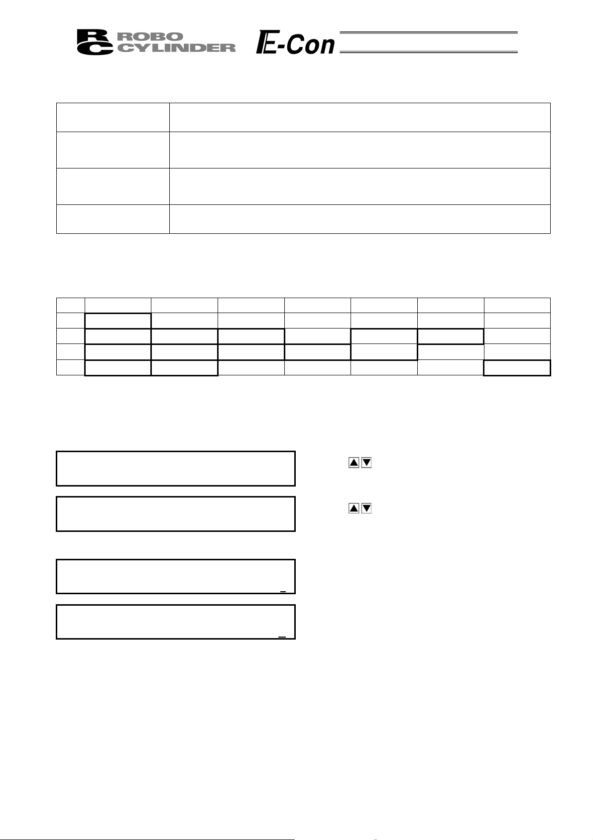
For the modes, select one of the 5 options as it appears on the above screen.
To select, move the cursor to the mode desired and confirm using the Return Key.
Category of Modes
1. * Edit/Teach Edit and numeric input function for position data table
2. * Monitor RC Controller status display
3. * Error list Alarm content detailed display
4. * User Parameter Setting of axis zone signal output range and axis
5. * User Adjustment Setting for enabling or disabling of temporary stop (hold) input and actuator
integrated RC controller.
Mode Select A. 00
* User Ad
ustment
Display screen
14
Page 19

8-4 Edit/Teaching
A
A
A
8-4-1 Edit/Teach Screen
When “*Edit/Teach” is selected on the Mode Select screen, the Edit/Teach screen is displayed.
The Edit/Teach screen has the 6 items as follows:
Mode Select Edit/Teach
Monitor
Error List
User
Parameter
User
Adjustment
Edit/Teach A. 00
* MDI
MDI
dd
Delete
Clear
ll Clear
Direct Teach
Edit/Teach A. 00
*
dd
Edit/Teach A. 00
* Delete
Edit/Teach A. 00
* Clear
Edit/Teach A. 00
* All Clear
Edit/Teach A. 00
* Direct Teach
15
Page 20

You can change the screens by using the arrow keys (
* MDI: Numerically inputs the position data directly from the ten numerical keys
(input example: Page 20 in this manual).
* Add: Adds the position data into the assigned position data number
(input example: Page 25 in this manual).
* Delete: Deletes position data (input example: Page 26 in this manual).
* Clear: Resets the position data (input example: Page 27 in this manual).
* All Clear: Resets all of the 16 position data (input example: Page 28 in this manual).
The position data table will display by selecting and determining MDI
* Direct Teach: Turns off the servo and places the slider at the desired position by moving it by hand and
incorporates the position into the position data (input example: Page 23 in this manual).
) and press the return key.
8-4-2 Position Data Table
When MDI is selected and determined, the contents of the position data table are displayed.
The position data table can be changed among the forms of 3 positions (No. 0 - No. 2), 8
Positions (No.1 - No.7) and 16 positions (No.0 - No.15) according to PIO pattern setting of the user
parameter.
No. Position Speed ACC • DEC Push % Range ACC MAX ABS/INC
0 * *mm/s *G *% *mm * 0
1 * *mm/s *G *% *mm * 0
2 * *mm/s *G *% *mm * 0
3 * *mm/s *G *% *mm * 0
4 * *mm/s *G *% *mm * 0
5 * *mm/s *G *% *mm * 0
6 * *mm/s *G *% *mm * 0
7 * *mm/s *G *% *mm * 0
8 * *mm/s *G *% *mm * 0
9 * *mm/s *G *% *mm * 0
10 * *mm/s *G *% *mm * 0
11 * *mm/s *G *% *mm * 0
12 * *mm/s *G *% *mm * 0
13 * *mm/s *G *% *mm * 0
14 * *mm/s *G *% *mm * 0
15 * *mm/s *G *% *mm * 0
Position Data Table
Use either the Return Key or
position number changes. In the display screen, only the single content of one position number will be
displayed.
MDI No. 00 A. 00
Position A
Key to execute transfer of the content. Use either of
Numbers following “No.” indicate the position number.
The numbers following “A.” indicate the axis number.
*
Indicates the following:
A: ABS (Absolute Positioning)
I: INC (Incremental Positioning)
Keys for
16
Page 21

The following are the descriptions of the setting items:
(1) Position: The desired move location from home in millimeters.
- Absolute Positioning:
Moves the actuator to the desired location in reference to the home location. Inputting
negative values is not possible.
- Relative Positioning:
Moves the actuator to the desired position in reference to the current position. Inputting
negative values is possible. In this case (during negative direction of the display
coordinate), first select Relative Positioning using (7) ABS/INC.
* By pressing the
ABS/INC Input Screen.
Caution: There are cases when the input value may be rounded off to the least
common denominator multiple of the controller.
(2) Speed - The speed when moving the actuator (mm/sec).
The default value will depend on the actuator type.
(3) Acc/Dec - The acceleration/deceleration setting for the move to the corresponding position (in G’s).
The default value will depend on the actuator type.
(4) Push% - Selects the positioning mode or push mode.
The default value is set as 0.
0: Positioning Mode (normal movement)
Besides 0: Push Mode (%)
- In case of push mode, data number is the servo motor current control value during push.
Uses a value that matches the actuator type with a maximum value of 70%.
Key once from the Position Input Screen will move the screen to
17
Page 22

(5) Range - As for the range, depending on the setting in the push as either 0 or other than 0, this
function will vary.
(A) Push = 0 (Positioning Mode)
- The positioning mode uses range value as a location to turn ON the position complete
output prior to reaching the actual position.
- The default value will depend on the actuator type. (see diagram A).
(B) Push ≠ 0 (Push Mode)
- The push mode uses the range value as the distance of the push.
- When the push direction is towards home, enter a negative value in the range column.
Speed
(4) When push = 0
(1) Distance up to the position
Speed
(4) When push ≠ 0
(1) Distance up to the position
Transfer distance Transfer distance
(6) Range Value (6) Range Value
(6) MAX Acceleration
- Selects either the assigned acceleration or the maximum acceleration. Inputs are either 1
or 0. The default value is set as 0.
0: Assigned acceleration
The value placed in (3) will be used as the actual acceleration value and
deceleration value.
1: Maximum acceleration
This will automatically utilize the maximum acceleration matched to the load.
Deceleration remains as the assigned value in (3).
(6) When acceleration only MAX = 0
Speed
(3) The value set in
acceleration/deceleration
(6) When acceleration only MAX = 1
The maximum acceleration
Speed
matches the load
The value set in
acceleration/deceleration
Transfer
distance
Transfer
distance
(7) ABS/INC - Select either the absolute or incremental positioning.
0: Absolute positioning (ABS)
1: Incremental positioning (INC)
The default value is 0, absolute positioning (ABS).
18
Page 23

8-4-3 Data Input
There are two methods of inputting the position data.
(1) MDI numeric input:
Method of numerically inputting the position data directly from the ten numerical keys of the Data Input
Pendant.
(2) Direct Teach:
Method of turning off the servo, placing the slider at the desired position by moving it by hand and
teaching the position (current position) to the position data table.
Caution: When the position data is first input by the method of Direct Teach after
power-on or alarm raising, it is required to have homed the actuator in
advance.
The Data Input Pendant has no function of homing the actuator.
Execute Direct Teach after homing with the PLC in advance.
19
Page 24
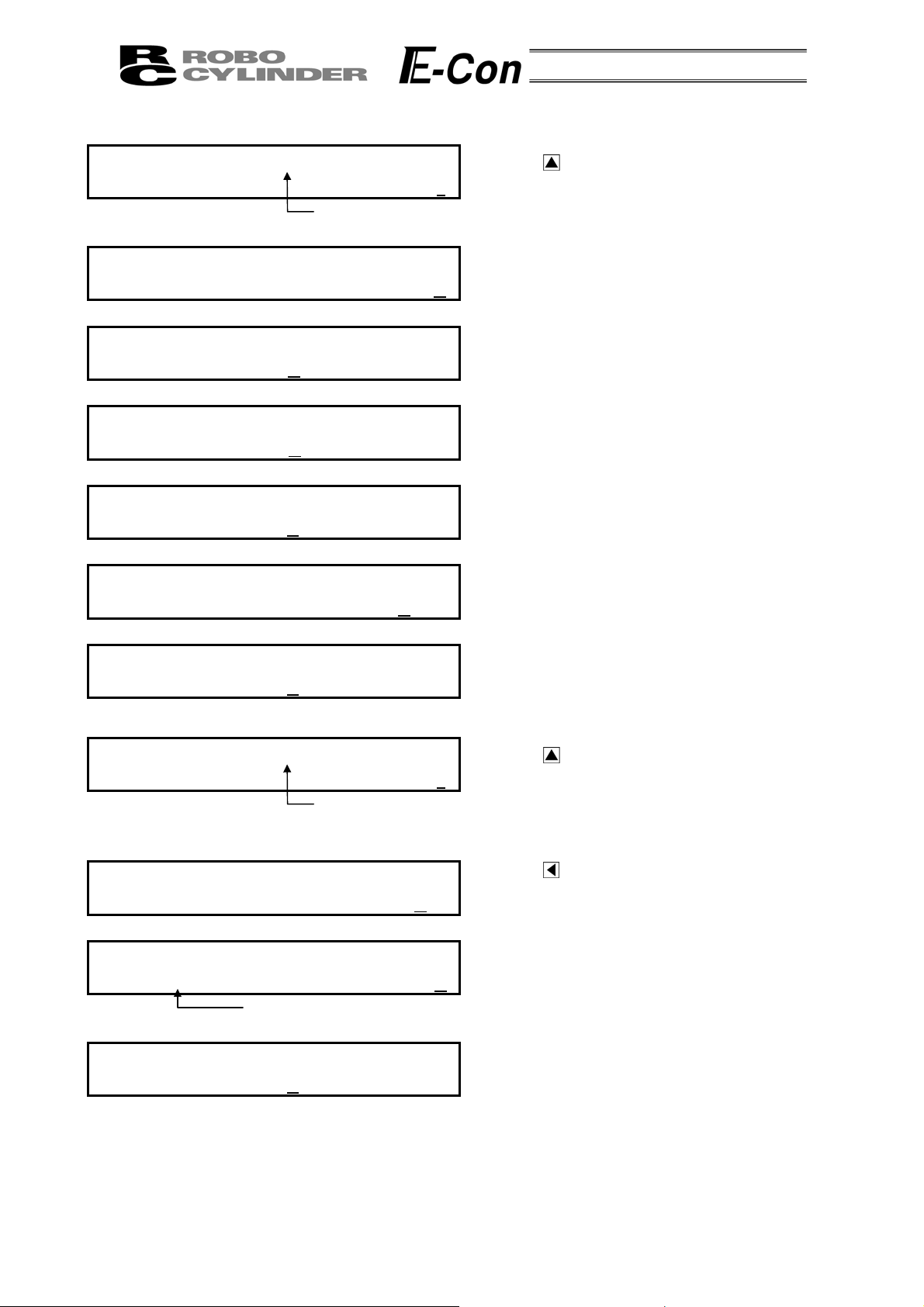
(1) MDI Numeric Input
Position No. 0
Position No. 1
Position No. 2
Position No. 3
Data not assigned utilizes default value. The example here is based on initial status during shipment (when
data is all clear).
You may input data from position data table similar to the table below.
No. Position Speed ACC • DEC Push % Range ACC MAX ABS/INC
0 0.00 125 mm/s 0.20 G 0% 0.10mm 0 0
1 50.00 100 mm/s 0.10 G 0% 0.20mm 1 0
2 80.00 100 mm/s 0.10 G 40% 5.00mm 0 0
3 10.00 20 mm/s 0.20 G 0% 0.10mm 0 1
Absolute positioning mode
Position 0mm
Absolute positioning mode
Position 50mm, Speed 100mm/s, ACC • DEC 0.1G
Range 0.2mm, ACC MAX 1
Absolute push mode
Position 80mm, Speed 100mm/s, ACC • DEC 0.1G
Push 40%, Range 5mm
Incremental positioning mode
Position 10mm, speed 20mm/s
Position Data Table
Input the data inside the thick line (see above table). The default values will be used for the data outside the
thick-lined frame. By inputting the position data, the default value will automatically input.
The default values (Speed, ACC • DEC and Range) will vary according to actuator machine type (in this
example: RSA Low speed type).
Mode Select A. 00
* Edit/Teach
Edit/Teach A. 00
* MDI
Input using position number 0.
MDI No. 00 A. 00
Position A
MDI No. 00 A. 00
Position A 0
Using the Key in the Mode Select Screen,
select Edit/Teach and choose using the Return Key.
Using the
MDI and choose using the Return Key.
The screen will turn into the Input Screen for Position.
Key in the Edit/Teach Screen, select
*
Using the Numeric Key, press 0 and the Return Key.
.
20
Page 25

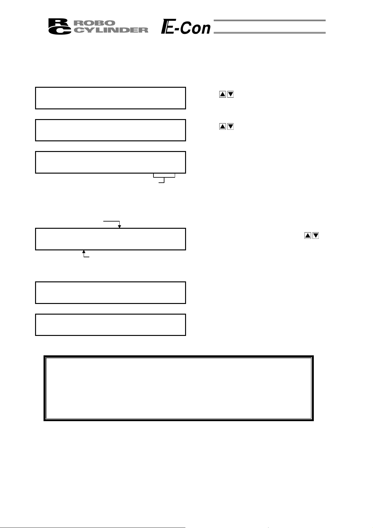
p
p
A
g
A
A
A
MDI No. 00 A. 00
S
eed 125 mm/s
Input using position number 1
MDI No. 01 A. 00
Position A
MDI No. 01 A. 00
Position A 5
MDI No. 01 A. 00
S
eed 100 mm/s
MDI No. 01 A. 00
CC•DEC 0.1 G
MDI No. 01 A. 00
Push %
MDI No. 01 A. 00
Ran
MDI No. 01 A. 00
MDI No. 01 A. 00
e 0.2mm
CC MAX 1
BS Æ 0 INC Æ 1 0
Position number 1
0 %
*
0
The screen will turn into the Input Screen for Speed.
The default value will be utilized as is. Since other
data will use the default value, input for position
number 0 will end here.
Next, position number 1 input will be executed.
Press the
The screen will turn into the Input Screen for Position.
Use the Numeric Keys to input 50 and then, press the
Return Key.
The screen will turn into the Input Screen for Speed.
Use the Numeric Keys to input 100 and then, press
the Return Key.
The screen will turn into the Input Screen for ACC •
DEC. Use the Numeric Keys to input 0.1 and then,
press the Return Key.
The screen will turn into the Input Screen for Push %.
The default value will be utilized as is, so press the
Return Key.
The screen will turn into the Input Screen for Range.
Use the Numeric Keys to input 0.2 and then, press
the Return Key.
The screen will turn into the Input Screen for ACC
MAX. Use the Numeric Key to input 1 and then, press
the Return Key.
The screen will turn into the Input Screen for
BS/INC. The default value will be utilized as is, so
press the Return key.
Input for position number 1 will end here.
Next, position number 2 input will be executed.
Key to advance position number to 1.
21
Page 26
Input using position number 2
p
A
g
A
A
p
MDI No. 02 A. 00
Position A
MDI No. 02 A. 00
Position A 8
MDI No. 02 A. 00
S
eed 100 mm/s
MDI No. 02 A. 00
CC•DEC 0.1 G
MDI No. 02 A. 00
Push % 4
MDI No. 02 A. 00
Ran
MDI No. 02 A. 00
Input using position number 3
MDI No. 03 A. 00
Position A
Input using MDI
MDI No. 03 A. 00
MDI No. 03 A. 00
Position I 10.0
MDI No. 03 A. 00
S
e 5mm
CC MAX 0
BS Æ 0 INC Æ 1 1
INC
(Relative positioning)
eed 20 mm/s
Position number 2
0 %
Position number 3
*
0
*
0
Press the Key to advance position number to 2.
The screen will turn into the Input Screen for Position.
Use the Numeric Keys to input 80 and then, press the
Return Key.
The screen will turn into the Input Screen for Speed.
Use the Numeric Keys to input 100 and then, press
the Return Key.
The screen will turn into the Input Screen for ACC •
DEC. Use the Numeric Keys to input 0.1 and then,
press the Return Key.
The screen will turn into the Input Screen for Push %.
Use the Numeric Keys to input 40 and then, press the
Return Key.
The screen will turn into the Input Screen for Range.
Use the Numeric Key to input 5 and then, press the
Return Key.
Input for position number 2 will end here.
Next, position number 3 input will be executed.
Press the Key to advance position number to 3.
The screen will turn into the Input Screen for Position.
Press the Key to change screen into ABS/INC
Display Screen. Use the Numeric Key to input 1 and
then, press the Return Key.
The screen will turn into the Input Screen for Position.
Use the Numeric Keys to input 10 and then, press the
Return Key.
The screen will turn into the Input Screen for Speed.
Use the Numeric Keys to input 20 and then, press the
Return Key.
Input for MDI will end here.
22
Page 27
(2) Direct Teach
A
By this method, the slider or rod is moved by hand to place it at the desired position and the current
position is incorporated into the position data table.
In this example, data is input for position number 4 by Direct Teach.
Mode Select A. 00
* Edit/Teach
Edit/Teach A. 00
* Direct Teach
Direct Teach A. 00
Servo OFF 51.23F
Position number 4
Incorporate? No. 04 A. 00
Direct Teach A. 00
Servo OFF 51.23F
Mode Select A. 00
* Edit/Teach
Displays the current position.
* Although this is displayed even
when homing is incomplete, it
is not an accurate value.
* Y Æ 1 N Æ 0
Displays the old position data.
It is not the desired position
determined in the previous screen.
Using the Key in the Mode Select Screen,
select Edit/Teach and choose using the Return Key.
Using the
Direct Teach and choose using the Return Key.
The servo is turned OFF and the current position is
displayed. Under this condition, move the slider or
rod by hand to a desired position.
(In the case of the actuator with brake, release the
brake.)
fter determining the desired position, press the
Return key.
Change the position number to 4 using keys.
Press 1 on the numeric key.
(If the slider or rod moves before pressing 1,
determine a desired position again.)
To cancel the data, press 0.
In either case, the screen returns to the previous
screen.
Press the ESC key twice to return the screen to the
Mode Select screen.
Key in the Edit/Teach Screen, select
Caution: Input any data (speed, acceleration/deceleration, etc.) other than position by
MDI.
When the position data is first input by the method of Direct Teach after
power-on or alarm raising, it is required to have homed the actuator in advance.
The Data Input Pendant has no function of homing the actuator.
Execute Direct Teach after homing with the PLC in advance.
23
Page 28

8-4-5 Add • Delete
In this section, we will give specific examples of how to add • delete and clear data in the position
table.
(1) Add: Adds the position data into the assigned position data number location.
(2) Delete: Deletes assigned position data.
(3) Clear: Resets the assigned position data.
(4) All Clear: Resets all of 16 position data.
24
Page 29
A
A
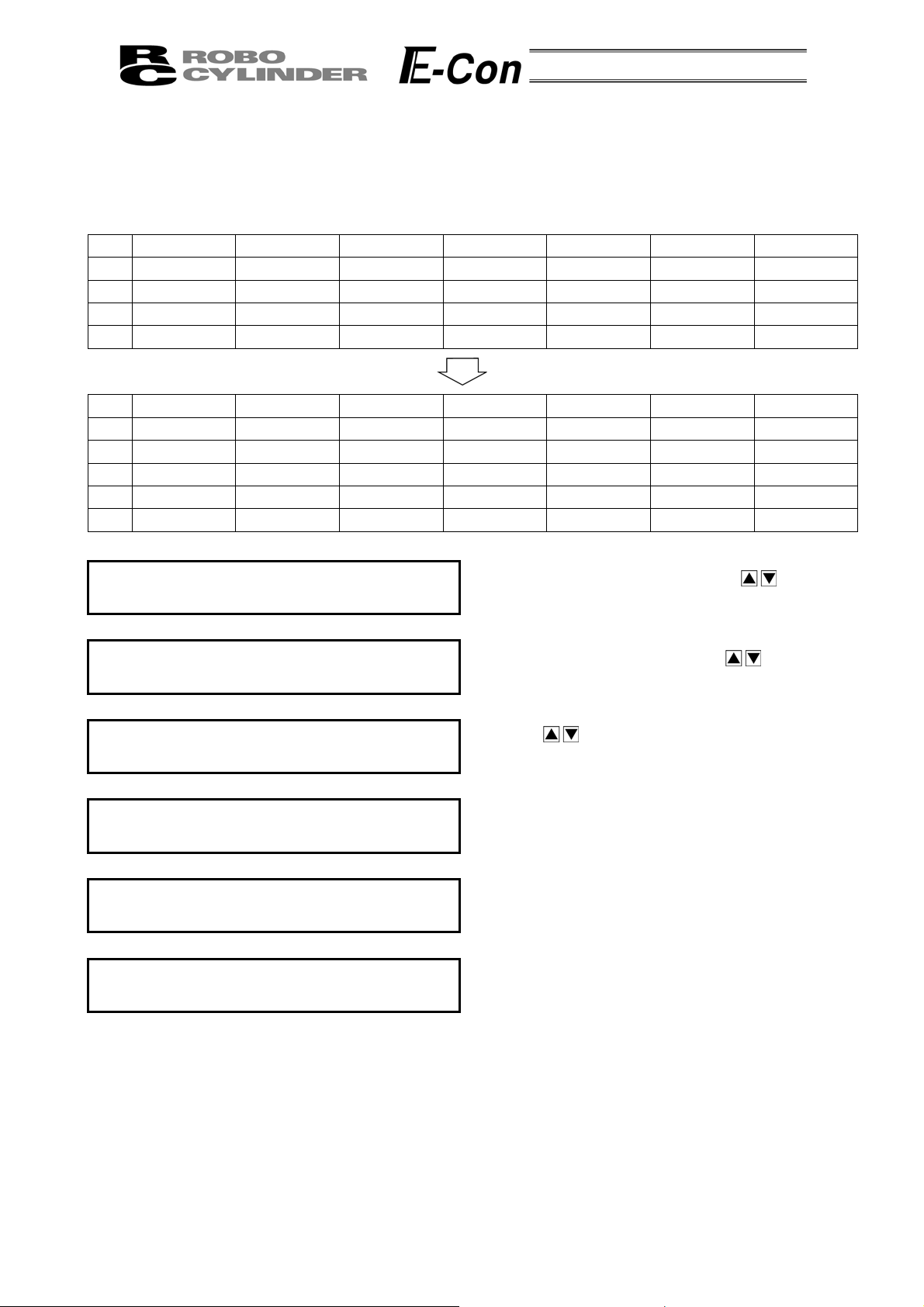
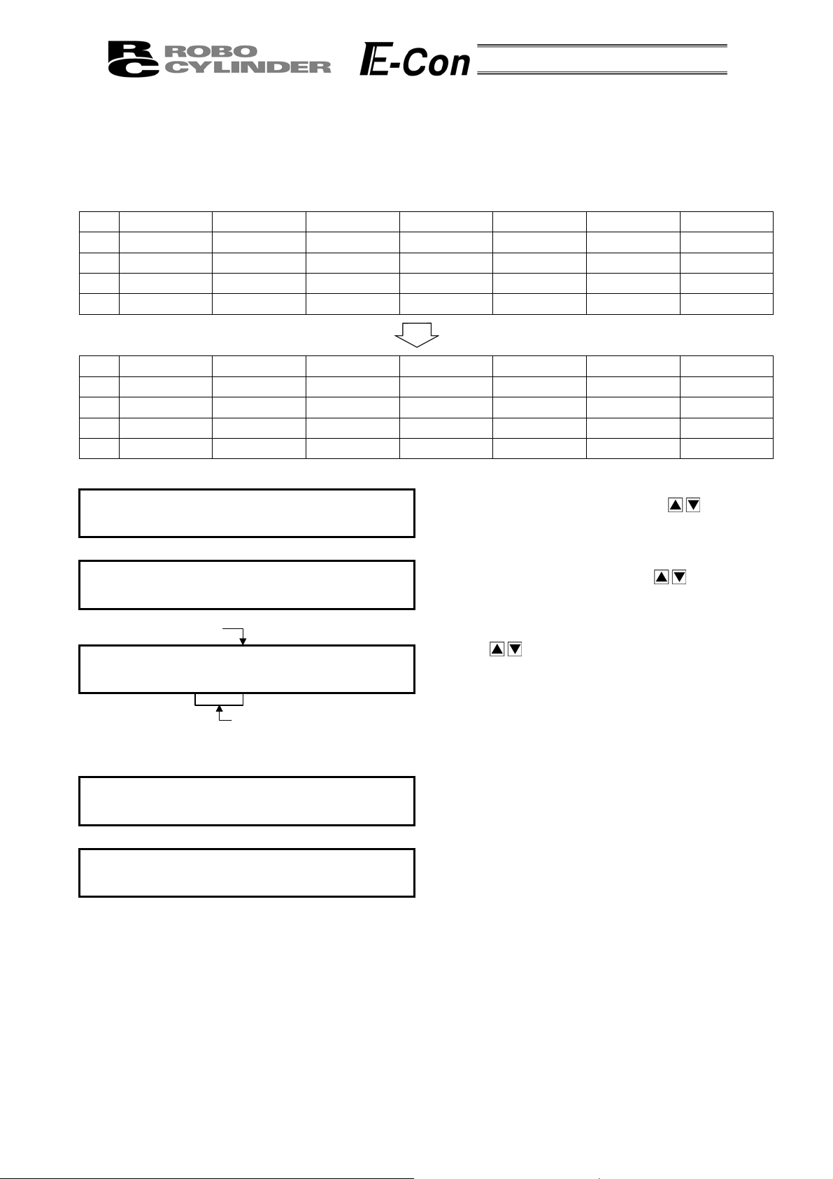
(1) Add:
The Add operation procedure is explained below. A blank row is inserted into any position number.
In this example, a blank row is inserted into position number 2.
The position data table becomes as shown below.
No. Position Speed ACC • DEC Push % Range ACC MAX ABS/INC
0 0.00 125 mm/s 0.20 G 0% 0.10mm 0 0
1 50.00 100 mm/s 0.10 G 0% 0.20mm 1 0
2 80.00 100 mm/s 0.10 G 40% 5.00mm 0 0
3 10.00 20 mm/s 0.20 G 0% 0.10mm 0 1
No. Position Speed ACC • DEC Push % Range ACC MAX ABS/INC
0 0.00 125 mm/s 0.20 G 0% 0.10mm 0 0
1 50.00 100 mm/s 0.10 G 0% 0.20mm 1 0
2 * * mm/s * G * % * mm * 0
3 80.00 100 mm/s 0.10 G 40% 5.00mm 0 0
4 10.00 20 mm/s 0.20 G 0% 0.10mm 0 1
Mode Select A. 00
* Edit/Teach
Edit/Teach A. 00
*
dd
Add? No. 2 A. 00
80.00 Y Æ 1 N Æ 0
Add? No. 2 A. 00
* Y Æ 1 N Æ 0
Edit/Teach A. 00
*
dd
Mode Select A. 00
* Edit/Teach
In the Mode Select Screen, using the
select Edit/Teach and then, press the Return Key.
In the Edit/Teach screen, using the
select Add and then, press the Return Key.
Using the Keys, change the position number
into 2.
Pressing 1 on the Numeric Key will insert a blank
point and then, the screen will return to the
Edit/Teach Screen.
Press the ESC Key once to return the screen back to
Mode Select Screen.
Keys,
Keys,
25
Page 30
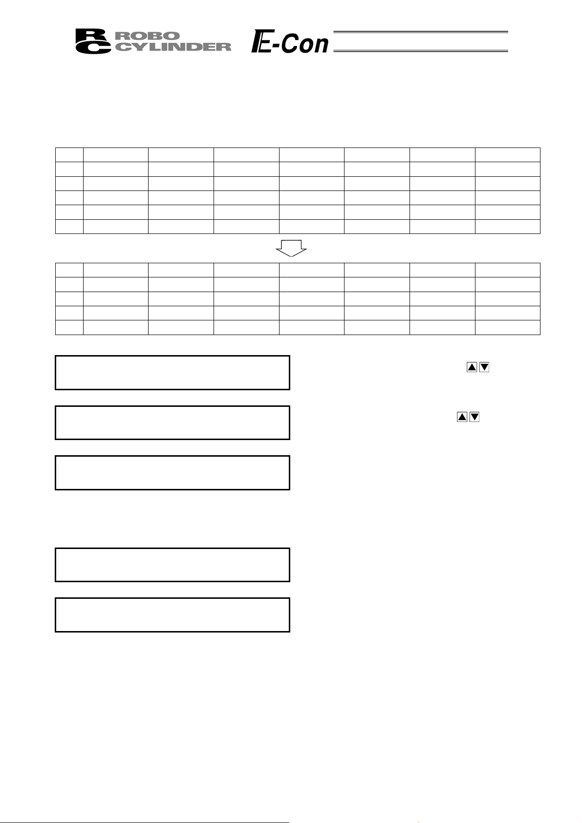
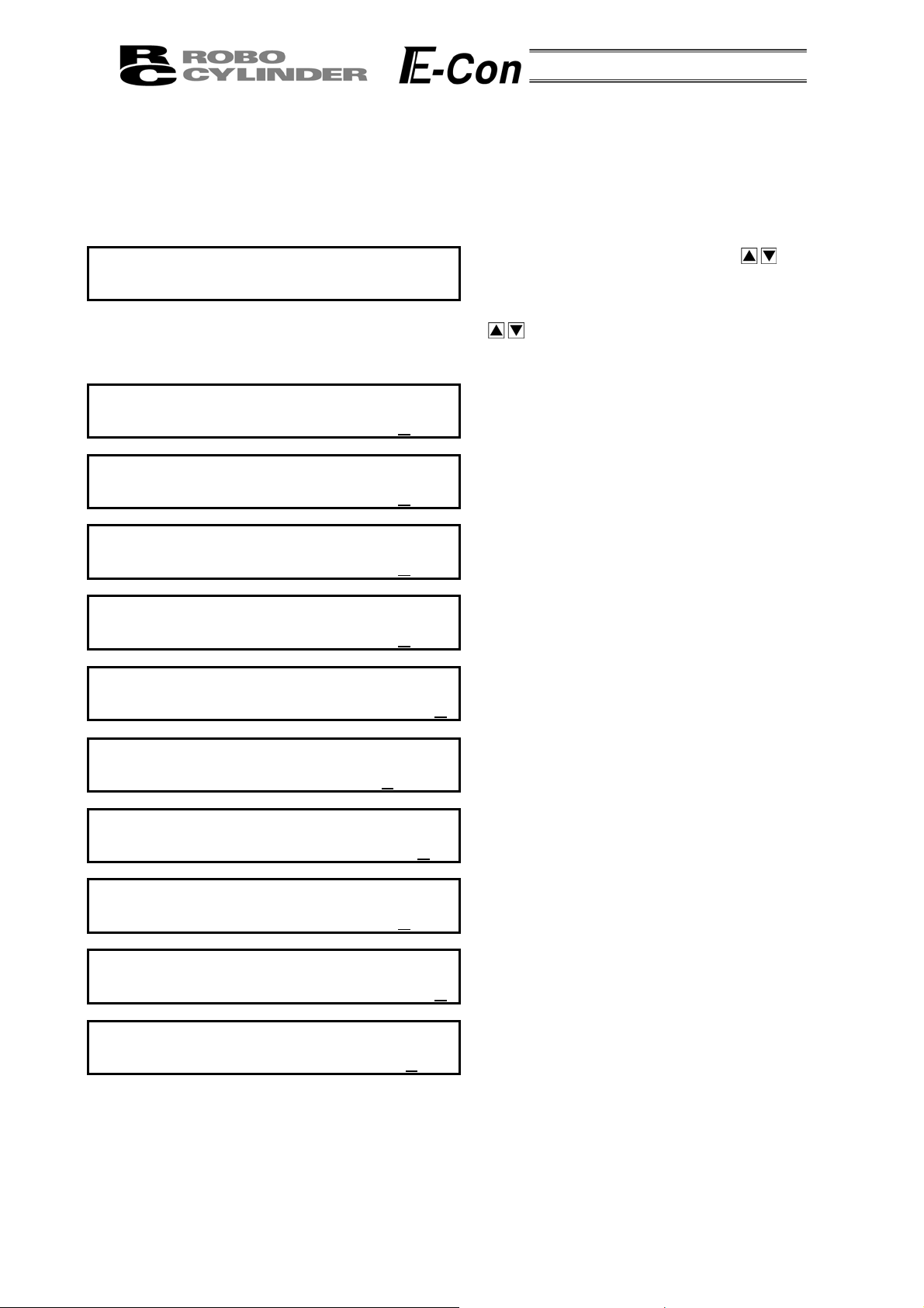
(2) Delete:
The Delete operation procedure is explained below. The data of any position number is deleted.
In this example, the data of position number 2 is deleted.
The position data table becomes as shown below.
No. Position Speed ACC • DEC Push % Range ACC MAX ABS/INC
0 0.00 125 mm/s 0.20 G 0% 0.10mm 0 0
1 50.00 100 mm/s 0.10 G 0% 0.20mm 1 0
2 * * mm/s * G * % * mm * 0
3 80.00 100 mm/s 0.10 G 40% 5.00mm 0 0
4 10.00 20 mm/s 0.20 G 0% 0.10mm 0 1
No. Position Speed ACC • DEC Push % Range ACC MAX ABS/INC
0 0.00 125 mm/s 0.20 G 0% 0.10mm 0 0
1 50.00 100 mm/s 0.10 G 0% 0.20mm 1 0
2 80.00 100 mm/s 0.10 G 40% 5.00mm 0 0
3 10.00 20 mm/s 0.20 G 0% 0.10mm 0 1
Mode Select A. 00
* Edit/Teach
Edit/Teach A. 00
* Delete
Delete? No. 2 A. 00
* Y Æ 1 N Æ 0
Edit/Teach A. 00
* Delete
Mode Select A. 00
* Edit/Teach
In the Mode Select Screen, using the
select Edit/Teach and then, press the Return Key.
In the Edit/Teach screen, using the
select Add and then, press the Return Key.
Using the Keys, change the position number into 2.
Pressing 1 on the Numeric Key will delete position
number 2 and then, the screen will return to the
Edit/Teach Screen. To cancel, press 0.
In either case, the screen will return to the previous
screen.
Press the ESC Key once to return the screen back to
Mode Select Screen.
Keys,
Keys,
26
Page 31
(3) Clear:
The Clear operation procedure is explained below. The data of any position number is cleared.
In this example, the data of position number 1 is cleared.
The position data table becomes as shown below.
No. Position Speed ACC • DEC Push % Range ACC MAX ABS/INC
0 0.00 125 mm/s 0.20 G 0% 0.10mm 0 0
1 50.00 100 mm/s 0.10 G 0% 0.20mm 1 0
2 80.00 100 mm/s 0.10 G 40% 5.00mm 0 0
3 10.00 20 mm/s 0.20 G 0% 0.10mm 0 1
No. Position Speed ACC • DEC Push % Range ACC MAX ABS/INC
0 0.00 125 mm/s 0.20 G 0% 0.10mm 0 0
1 * * mm/s * G * % * mm * 0
2 80.00 100 mm/s 0.10 G 40% 5.00mm 0 0
3 10.00 20 mm/s 0.20 G 0% 0.10mm 0 1
Mode Select A. 00
* Edit/Teach
Edit/Teach A. 00
* Clear
Position number 1
Clear? No. 01 A. 00
50.00 Y Æ 1 N Æ 0
Position data for
position number 1
Edit/Teach A. 00
* Clear
Mode Select A. 00
* Edit/Teach
In the Mode Select Screen, using the
select Edit/Teach and then, press the Return Key.
In the Edit/Teach screen, using the
select Add and then, press the Return Key.
Using the
to 2. Pressing 1 on the Numeric Key will clear
in
position number 1 and then, the screen will return to
the Edit/Teach Screen. To cancel, press 0.
In either case, the screen will return to the previous
screen.
Press the ESC Key once to return the screen back to
Mode Select Screen.
Keys, change the position number
Keys,
Keys,
27
Page 32

(3) All Clear:
A
A
The data of all the position numbers is cleared.
The position data table becomes as shown below.
No. Position Speed ACC • DEC Push % Range ACC MAX ABS/INC
0 0.00 125 mm/s 0.20 G 0% 0.10mm 0 0
1 50.00 100 mm/s 0.10 G 0% 0.20mm 1 0
2 80.00 100 mm/s 0.10 G 40% 5.00mm 0 0
3 10.00 20 mm/s 0.20 G 0% 0.10mm 0 1
No. Position Speed ACC • DEC Push % Range ACC MAX ABS/INC
0 * * mm/s * G * % * mm * 0
1 * * mm/s * G * % * mm * 0
2 * * mm/s * G * % * mm * 0
3 * * mm/s * G * % * mm * 0
Mode Select A. 00
* Edit/Teach
Edit/Teach A. 00
*
ll Clear
All Clear? A. 00
Y Æ 1 N Æ 0
Edit/Teach A. 00
*
ll Clear
Mode Select A. 00
* Edit/Teach
In the Mode Select Screen, using the
select Edit/Teach and then, press the Return Key.
In the Edit/Teach Screen, using the
select All Clear and then, press the Return Key.
Pressing 1 on the Numeric Key will clear all data and
then, the
To cancel, press 0.
In either case, the screen will return to the previous
screen.
Press the ESC Key once to return the screen back to
Mode Select Screen.
screen will return to the Edit/Teach Screen.
Keys,
Keys,
28
Page 33

8-4-5 Data Modification
You may write over all of the position data.
(1) MDI numeric input:
Input the position data directly from the ten numerical keys.
(2) Direct Teach:
Turns the servo OFF, manually move the slider to the desired location, and read that location into the
position table.
During data modification, carry out operation carefully as shown below.
* As for MDI numeric input, only the overwritten items input by the ten numerical keys will be modified.
* As for Direct Teach, the position data will be updated when the current position is read by the Return key.
There is no effect on any other items such as the speed.
* Once the position data has been cleared, the cleared data no longer remains anywhere. Therefore,
when the position data is registered next time, the Positioning Mode and the Absolute Positioning are
selected by default.
When the position data of the Push Mode or the Relative Positioning is cleared and registered again, be
sure to check all the items of the position data and input necessary data.
29
Page 34

8-5 Monitor
_
_
The I/O status or current position is displayed.
The displayed menu differs according to the controller type. In the case of RCP2/ERC, it also differs
according to the PIO pattern.
Mode Select A. 00
* Monitor
Monitor A. 00
Pos 0.00N mm
Monitor A. 00
Error No. 000
Monitor A. 00
Servo ON
Monitor A. 00
in Start OFF
Monitor A. 00
in Pos No. 00
Monitor A. 00
in
RES ON
Monitor A. 00
in SON 00
Monitor A. 00
in
STP ON
Monitor A. 00
out Pos No. 00
Monitor A. 00
out PEND ON
Monitor A. 00
out HEND No. 00
In the Mode Select Screen, using the
select Monitor and then, press the Return Key.
Select the displayed item using the Return key or
key. Use the
Displays the current posit
Displays the error code number.
Displays the ON/OFF status of servo.
Displays the ON/OFF status of start input.
Displays the assigned position number.
Displays the ON/OFF status of reset input.
(RCS, E-Con)
Displays the ON/OFF status of servo ON input.
(RCS, E-Con)
Displays the ON/OFF status of temporary stop (hold)
input.
Displays the complete position number.
Displays the ON/OFF status of positioning complete
output.
Displays ON if homing is completed or OFF if homing
is not completed.
Keys to change the axis number.
ion.
Keys,
30
Page 35

_
A
A
Monitor A. 00
out ZONE ON
Monitor A. 00
out
ALM ON
Mode Select A. 00
* Monitor
8-6 Error List
The screen displays the nature of the error having occurred after the Data Input Pendant
connection.
Mode Select A. 00
* Error List
Error List List No. 0
Error No. 0E8
Displays ON/OFF status o
Displays ON/OFF status o
Press the ESC Key once to return the screen back to
Mode Select Screen.
In the Mode Select Screen, using the
select Edit/Teach and then, press the Return Key.
Select the displayed item using the Return key or
key.
Displays the error code number.
f zone output.
f alarm output.
Keys,
Error List List No. 0
, B Phase Disconnection
Error List List No. 0
xis No. 00
Error List List No. 0
1 Min
Mode Select A. 00
* Error List
Displays the error name.
Displays the ON/OFF status of servo.
Displays how many minutes ago the error occurred.
Press the ESC Key once to return the screen back to
Mode Select Screen.
31
Page 36
(
g
A
p
8-7 User Parameter
The User parameter assigns zone and soft limit ranges, actuator attributes and home direction.
Zone and soft limit are set within ±9999.99 (input unit: mm).
Home and servo parameters are determined by the actuator. Each setting for initial setting value
parameters is the registered default value for position data during teaching.
Mode Select A. 00
* User Parameter
User Para A. 00
+ Zone 150. 3
User Para A. 00
- Zone -0. 3
User Para A. 00
+ Limit 150. 3
User Para A. 00
- Limit -0. 3
User Para A. 00
Home
User Para A. 00
Initi. Vel 12
User Para A. 00
Initi. ACC 0.2
User Para A. 00
Ran
User Para A. 00
CC (1: MAX) 0
User Para A. 00
Push Com
CWO CCW1) 1
5mm/s
e 0. 10mm
255ms
0mm
0mm
0mm
0mm
0G
In the Mode Select Screen, using the
select User Parameter and then, press the Return
Key. Select the displayed item using the Return key
or
Key for input and then, press the Return Key.
Displays the zone limit +side.
Displays the zone limit -side.
Displays the soft limit + side.
Displays the soft limit - side.
Displays the assigned position number.
Displays the initial velocity value.
Displays the initial ACC • DEC value.
Displays initial positioning width value.
Displays the initial ACC MAX value.
Displays the push stop determination time.
key. To change the value, use the Numeric
Keys,
32
Page 37
A
A
A
A
A
User Para A. 00
Servo Gain
User Para A. 00
Hold Cur 2
User Para A. 00
Home Cur 5
User Para A. 00
t ES, DB Efct 1
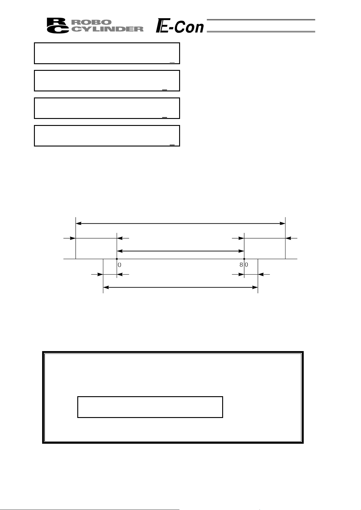
- When soft limit is modified at the customer site, please set a value which extends 0.3mm outside of the
effective area.
Example: When setting the effective area between 0mm~80mm
Soft limit + side: 80.3
Soft limit - side: -0.3
4%
0%
Soft Limit set in controller
Displays the number of the servo gain.
6
Displays the positioning hold current.
Displays the home current limit value.
Displays whether the dynamic brake is effective or
not effective at emergency stop time.
1: Effective, 0: Not effective (RCS, E-Con)
pproximately
0.3mm
Effective area
pproximately
0.1mm
Jog Increment allowable range after homing
- After changing the homing directi on, all saved position data will be cleared. As needed, please re-enter
the data.
- Reversed homing direction may be done on the Rod Type Actuator.
- Homing direction setting is reversed on the Folded Type (SSR • SMR) Actuator (0: Correct, 1: Reversed).
Caution: After changing any parameter, be sure to execute restarting by turning on the
power to the controller again or resetting the software. When resetting the
software, press the ESC key after changing the parameter.
The following is displayed on the screen.
Software Reset A. 00
* Reset? Y Æ 1 N Æ 0
Press 1 with the numeric key and then press the Return key.
Software is reset and the parameter change becomes effective.
pproximately
0.1mm
pproximately
0.3mm
* Regarding parameter, please refer to the RC Cont roller Operating Manual.
33
Page 38

8-8 User Adjustment
j
Adj
Adj
A
Adj
Adj
Adj
Setting is made for enabling or disabling temporary stop (hold) input and servo ON input.
The axis number setting is made for the integrated RC controller.
Mode Select A. 00
* User Ad
Disable hold input:
User Adjustment A. 00
Enable hold input:
User Adjustment A. 00
Integrated RC Controller axis number setting:
User Adjustment A. 00
User Adjustment A. 00
Disable servo ON input (E-Con and RCS series only)
User Adjustment A. 00
Enable servo ON input
User Adjustment A. 00
ustment No. 91
ustment No. 90
lloc. No. 0
ustment
ustment No. 2
ustment No. 93
ustment No. 92
Input 91
Input 90
Input axis number
Input 2
Input 93
Input 92
In the Mode Select Screen, using the
select User Adjustment and then, press the Return
Key.
Input 91 into the adjustment number and then, press
the Return Key. Afterwards, the controller must be
turned OFF.
Input 90 into the adjustment number and then, press
the Return Key. Afterwards, the controller must be
turned OFF.
Input the axis number into the allocation number and
then, press the Return Key.
Input 2 into the adjustment number and then, press
the Return Key. If this procedure is done on a
non-integrated controller, you will get error number
61. Afterwards, the controller must be turned OFF.
Input 93 into the adjustment number and then, press
the Return key. Afterwards, the controller must be
turned OFF.
Input 92 into the adjustment number and then, press
the Return key. Afterwards, the controller must be
turned OFF.
Keys,
Caution: Do not input any numeric values other than 2, 90 and 91 (92 and 93) into the
adjustment number.
34
Page 39

8-9 End
End is executed to save each setting or registration content of the Data Input Pendant.
Before removing the Data Input Pendant from the RC controller, be sure to execute End.
Operation:
Press the BEGIN/END key for more than 2.5 seconds.
In a case that data input ends, and the Data
Input Pendant needs to be removed
In a case that you reconnect and wish to
reopen
Op. Start / End
* End DU = Efct
Op. Start / End
* End DU = Non
Turn the RC Controller PORT Switch to OFF.
Then, remove the connector.
Op. Start / End
* Reconnection
Confirming Connection
IAI RC DU V. 1.66
Select Axis
* Axis No. 00
(in a case of multiple axes connection)
Or
Mode Select A. 00
* Edit/Teach
(in a case of single axis connection)
Caution: When multiple axes are connected with a controller link cable, after recycling
power of a controller that is not directly connected to the Data Input Pendant,
please execute a reconnect.
35
Page 40

9. Message Area
In the message screen, content during error and warning will be displayed.
Code No. Error Label Error Reset Reference
000~07F Controller Warning Yes Controller rejects command
080-0FF Controller Error Yes Error inside the controller
100~1FF DIP* Message Yes Input error, guide message, etc.
200~2FF DIP* Movement Release Yes Movement continuation impossible
300~3FF DIP Cold Start Error No DIP Power install or reconnect are necessary.
* DIP in the table refers to the Data Input Pendant.
9-1 Warning Label Error (Code No. 000h – 07Fh)
Warning message is cleared by recovery procedure as follows:
Release operation:
1. First, confirm the cause of the warning and resolve the problem.
2. Press down BEGIN/END Key.
Warning is probably due to the following possibilities:
- RS485 communication abnormality
- Data Input Pendant operational mistake
a) RS 485 communication related abnormality
Indicates occurrence of any abnormality on the RS485 communication line.
Cause: Influence by foreign noise or connections are not properly installed.
The Data Input Pendant and RC controller execute packet communication (move
instruction, data transfer, etc.) at all times. At this time, when data changes due to
noise, the RC controller will determine that it is incorrect data and will reject the data.
Solution: (1) Confirm the above causes. In the case of frequent warning occurrences, please
separately set the signal cable and power line.
(2) Be sure to use one unit to operate the RC controller.
See to it that the Data Input Pendant will not conflict with the PIO signal.
36
Page 41

9-2 Data Input Pendant Message Level Error
When you try to input an incorrect value by a Data Input Pendant operational mistake, a message
level error occurs.
9-3 Controller Error
Alarms detected from the controller side are displayed.
They are serious errors resulting from an abnormality with the servo control or electric system.
Please carefully read the operating manual of the controller you use and take measures.
For details of the alarm codes and solutions as well, refer to the same operating manual.
37
Page 42

Manual No.: ME0106-4A (December 2011)
Head Office: 577-1 Obane Shimizu-KU Shizuoka City Shizuoka 424-0103, Japan
TEL +81-54-364-5105 FAX +81-54-364-2589
website: www.iai-robot.co.jp/
Technical Support available in USA, Europe and China
Head Office: 2690 W. 237th Street, Torrance, CA 90505
TEL (310) 891-6015 FAX (310) 891-0815
Chicago Office: 1261 Hamilton Parkway, Itasca, IL 60143
TEL (630) 467-9900 FAX (630) 467-9912
Atlanta Office: 1220 Kennestone Circle, Suite 108, Marietta, GA 30066
TEL (678) 354-9470 FAX (678) 354-9471
website: www.intelligentactuator.com
Ober der Röth 4, D-65824 Schwalbach am Taunus, Germany
TEL 06196-88950 FAX 06196-889524
SHANGHAI JIAHUA BUSINESS CENTER A8-303, 808, Hongqiao Rd. Shanghai 200030, China
TEL 021-6448-4753 FAX 021-6448-3992
website: www.iai-robot.com
The information contained in this document is subject to change without notice for purposes of
product improvement.
Copyright © 2011. Dec. IAI Corporation. All rights reserved.
11.12.000
 Loading...