

Page 1
ROBO Cylinder
RCA2 Actuator
Rod Type
Instruction Manual
Tenth Edition
[Slim Small ROBO Cylinders] RC2AC, RA2AR
[Slim Small ROBO Cylinders] SD3NA, SD4NA
[Slim Small ROBO Cylinders] GD3NA, GD4NA
[Slim Small ROBO Cylinders] GS3NA, GS4NA
[Slim Small ROBO Cylinders] RP3NA, RP4NA
[Slim Small ROBO Cylinders] RN3NA, RN4NA
Slim types
Short types
(nut affixing types)
Short types
(tapped-hole mounting types)
Single guide types
Double guide types
Slide unit types
IAI America, Inc.
RN3N, RN4N
RP3N, RP4N
GS3N, GS4N
GD3N, GD4N
SD3N, SD4N
Page 2

Page 3

[Important]
x This Instruction Manual is original.
x The product cannot be operated in any way unless expressly specified in this Instruction Manual.
IAI shall assume no responsibility for the outcome of any operation not specified herein.
x Information contained in this Instruction Manual is subject to change without notice for the
purpose of product improvement.
x If you have any question or comment regarding the content of this manual, please contact the
IAI sales office near you.
x Using or copying all or part of this Instruction Manual without permission is prohibited.
x The company names, names of products and trademarks of each company shown in the
sentences are registered trademarks.
Please Read Before Use
Thank you for purchasing our product.
This Instruction Manual describes all necessary information items to operate this product safely
such as the operation procedure, structure and maintenance procedure.
Before the operation, read this manual carefully and fully understand it to operate this product
safely. The enclosed CD or DVD in this product package includes the Instruction Manual for this
product.
For the operation of this product, print out the necessary sections in the Instruction Manual or
display them using the personal computer.
After reading through this manual, keep this Instruction Manual at hand so that the operator of this
product can read it whenever necessary.
Page 4

CE Marking
If a compliance with the CE Marking is required, please follow Overseas Standards Compliance
Manual (ME0287) that is provided separately.
Page 5

Table of Contents
Safety Guide ······················································································································· 1
Handling Precautions·········································································································· 8
1. Part Names ················································································································· 11
1.1 Slim Types
RA2AC (Motor coupling types), RA2AR (Motor reversing types) ····································11
1.2 Short Types (Nut Affixing Types)
RN3NA, RN3N (Lead screw, Ball screw), RN4NA, RN4N (Lead screw, Ball screw)······ 12
1.3 Short Types (Tapped-hole Mounting Types)
RP3NA, RP3N (Lead screw, Ball screw), RP4NA, RP4N (Lead screw, Ball screw) ······ 12
1.4 Single Guide Types
GS3NA, GS3N (Lead screw, Ball screw), GS4NA, GS4N (Lead screw, Ball screw)······ 13
1.5 Double Guide Types
GD3NA, GD3N (Lead screw, Ball screw), GD4NA, GD4N (Lead screw, Ball screw)····· 13
1.6 Slide Unit Types
SD3NA, SD3N (Lead screw, Ball screw), SD4NA, SD4N (Lead screw, Ball screw) ······ 14
2. External Diagrams······································································································· 15
2.1 Slim Type (Motor coupling type) RA2AC········································································· 15
2.2 Slim Type (Motor reversing type) RA2AR ······································································· 15
2.3 Short Types (Nut rotating types) RN3NA, RN3N (Lead screw, Ball screw) ···················· 16
2.4 Short Types (Nut rotating types) RN4NA, RN4N (Lead screw, Ball screw) ···················· 16
2.5 Short Types (Tapped-hole mounting types) RP3NA, RP3N (Lead screw, Ball screw) ··· 17
2.6 Short Types (Tapped-hole mounting types) RP4NA, RP4N (Lead screw, Ball screw) ··· 17
2.7 Single Guide Types GS3NA, GS3N (Lead screw, Ball screw)········································ 18
2.8 Single Guide Types GS4NA, GS4N (Lead screw, Ball screw)········································ 18
2.9 Double Guide Types GD3NA, GD3N (Lead screw, Ball screw)······································ 19
2.10 Double Guide Types GD4NA, GD4N (Lead screw, Ball screw)······································ 19
2.11 Slide Unit Types SD3NA, SD3N (Lead screw, Ball screw) ············································· 20
2.12 Slide Unit Types SD4NA, SD4N (Lead screw, Ball screw) ············································· 20
3. Cable Drawings··········································································································· 21
3.1 ASEP Controller Cables·································································································· 21
3.2 ACON, ASEL Controller Cables ······················································································ 22
4. Options························································································································ 24
4.1 Connector Cable Exit Direction Changed ······································································· 24
4.2 Low Power Consumption Type ······················································································· 24
5. Checking after Unpacking ··························································································· 25
5.1 Included Items················································································································· 25
5.2 Instruction Manuals Relating to This Product·································································· 25
5.3 How to Read Model Nameplate······················································································ 26
5.4 How to Read Model········································································································· 26
6. Specifications ·············································································································· 27
Page 6

7. Installation and Storage/Preservation Environment ···················································· 36
7.1 Installation Environment·································································································· 36
7.2 Storage/Preservation Environment ················································································· 37
8. Installation ··················································································································· 38
8.1 Slim Types
RA2AC (Motor coupling types), RA2AR (Motor reversing types) ··································· 38
8.1.1 Installation of Actuator ························································································· 38
8.2 Short Types (Nut affixing types)
RN3NA, RN3N (Lead screw, ball screw), RN4NA, RN4N (Lead screw, ball screw) ······ 39
8.2.1 Installation of Actuator ························································································· 39
8.2.2 Installation of Detent···························································································· 40
8.2.3 Installation of Flange ··························································································· 49
8.2.4 Installation from Rear Side ·················································································· 50
8.3 Short Types (Tapped-hole mounting types)
RP3NA, RP3N (Lead screw, ball screw), RP4NA, RP4N (Lead screw, ball screw) ······· 51
8.3.1 Installation of Actuator ························································································· 51
8.3.2 Installation of Detent···························································································· 53
8.3.3 Installation of Flange ··························································································· 62
8.3.4 Installation from Rear Side ·················································································· 63
8.4 Single Guide Types
GS3NA, GS3N (Lead screw, ball screw), GS4NA, GS4N (Lead screw, ball screw) ······ 64
8.5 Double Guide Types
GD3NA, GD3N (Lead screw, ball screw), GD4NA, GD4N (Lead screw, ball screw)······ 66
8.6 Slide Unit Types
SD3NA, SD3N (Lead screw, ball screw), SD4NA, SD4N (Lead screw, ball screw) ······· 68
9. Connecting with Controller ·························································································· 71
10. Notes on Operation ····································································································· 75
10.1 Placing a Load on the Actuator ······················································································· 75
10.2 How to Move Rod by Hand ····························································································· 75
10.3 Home Return ··················································································································· 76
10.3.1 Home Return Operation ······················································································ 76
11. Life ······························································································································ 78
11.1 Life of Actuator Using Ball Screws ·················································································· 78
11.2 Life of Actuator Using Lead Screws ················································································ 78
11.2.1 Relationship of Cycle Time and Product Life······················································· 78
12. Maintenance and Inspection ······················································································· 81
12.1 Inspection Items and Timings·························································································· 81
12.2 Visual Inspection of Exterior···························································································· 81
12.3 Cleaning ·························································································································· 81
12.4 Inspection of Interior········································································································ 82
12.5 Internal Cleaning ············································································································· 83
12.6 Greasing·························································································································· 83
12.6.1 Applicable Grease ······························································································· 83
12.6.2 Greasing Method································································································· 84
12.7 How to Replace Spiral Cover ·························································································· 85
Page 7

13. Warranty······················································································································ 88
13.1 Warranty Period··············································································································· 88
13.2 Scope of Warranty··········································································································· 88
13.3 Honoring the Warranty ···································································································· 88
13.4 Limited Liability················································································································ 88
13.5 Conditions of Conformance with Applicable Standards/Regulations, Etc.,
and Applications ·············································································································· 89
13.6 Other Items Excluded from Warranty·············································································· 89
Change History ················································································································· 90
Page 8

Page 9

1
Safety Guide
“Safety Guide” has been written to use the machine safely and so prevent personal injury or
property damage beforehand. Make sure to read it before the operation of this product.
Safety Precautions for Our Products
The common safety precautions for the use of any of our robots in each operation.
No.
Operation
Description
Description
1 Model
Selection
Ɣ This product has not been planned and designed for the application
where high level of safety is required, so the guarantee of the protection
of human life is impossible. Accordingly, do not use it in any of the
following applications.
1) Medical equipment used to maintain, control or otherwise affect
human life or physical health.
2) Mechanisms and machinery designed for the purpose of moving or
transporting people (For vehicle, railway facility or air navigation
facility)
3) Important safety parts of machinery (Safety device, etc.)
Ɣ Do not use the product outside the specifications. Failure to do so may
considerably shorten the life of the product.
Ɣ Do not use it in any of the following environments.
1) Location where there is any inflammable gas, inflammable object or
explosive
2) Place with potential exposure to radiation
3) Location with the ambient temperature or relative humidity exceeding
the specification range
4) Location where radiant heat is added from direct sunlight or other
large heat source
5) Location where condensation occurs due to abrupt temperature
changes
6) Location where there is any corrosive gas (sulfuric acid or
hydrochloric acid)
7) Location exposed to significant amount of dust, salt or iron powder
8) Location subject to direct vibration or impact
Ɣ For an actuator used in vertical orientation, select a model which is
equipped with a brake. If selecting a model with no brake, the moving
part may drop when the power is turned OFF and may cause an
accident such as an injury or damage on the work piece.
Page 10

2
No.
Operation
Description
Description
2 Transportation Ɣ When carrying a heavy object, do the work with two or more persons or
utilize equipment such as crane.
Ɣ When the work is carried out with 2 or more persons, make it clear who
is to be the leader and who to be the follower(s) and communicate well
with each other to ensure the safety of the workers.
Ɣ When in transportation, consider well about the positions to hold,
weight and weight balance and pay special attention to the carried
object so it would not get hit or dropped.
Ɣ Transport it using an appropriate transportation measure.
The actuators available for transportation with a crane have eyebolts
attached or there are tapped holes to attach bolts. Follow the
instructions in the instruction manual for each model.
Ɣ Do not step or sit on the package.
Ɣ Do not put any heavy thing that can deform the package, on it.
Ɣ When using a crane capable of 1t or more of weight, have an operator
who has qualifications for crane operation and sling work.
Ɣ When using a crane or equivalent equipments, make sure not to hang a
load that weighs more than the equipment’s capability limit.
Ɣ Use a hook that is suitable for the load. Consider the safety factor of the
hook in such factors as shear strength.
Ɣ Do not get on the load that is hung on a crane.
Ɣ Do not leave a load hung up with a crane.
Ɣ Do not stand under the load that is hung up with a crane.
3 Storage and
Preservation
Ɣ The storage and preservation environment conforms to the installation
environment. However, especially give consideration to the prevention
of condensation.
Ɣ Store the products with a consideration not to fall them over or drop due
to an act of God such as earthquake.
4 Installation
and Start
(1) Installation of Robot Main Body and Controller, etc.
Ɣ Make sure to securely hold and fix the product (including the work part).
A fall, drop or abnormal motion of the product may cause a damage or
injury.
Also, be equipped for a fall-over or drop due to an act of God such as
earthquake.
Ɣ Do not get on or put anything on the product. Failure to do so may
cause an accidental fall, injury or damage to the product due to a drop
of anything, malfunction of the product, performance degradation, or
shortening of its life.
Ɣ When using the product in any of the places specified below, provide a
sufficient shield.
1) Location where electric noise is generated
2) Location where high electrical or magnetic field is present
3) Location with the mains or power lines passing nearby
4) Location where the product may come in contact with water, oil or
chemical droplets
Page 11

3
No.
Operation
Description
Description
(2) Cable Wiring
Ɣ Use our company’s genuine cables for connecting between the actuator
and controller, and for the teaching tool.
Ɣ Do not scratch on the cable. Do not bend it forcibly. Do not pull it. Do
not coil it around. Do not insert it. Do not put any heavy thing on it.
Failure to do so may cause a fire, electric shock or malfunction due to
leakage or continuity error.
Ɣ Perform the wiring for the product, after turning OFF the power to the
unit, so that there is no wiring error.
Ɣ When the direct current power (+24V) is connected, take the great care
of the directions of positive and negative poles. If the connection
direction is not correct, it might cause a fire, product breakdown or
malfunction.
Ɣ Connect the cable connector securely so that there is no disconnection
or looseness. Failure to do so may cause a fire, electric shock or
malfunction of the product.
Ɣ Never cut and/or reconnect the cables supplied with the product for the
purpose of extending or shortening the cable length. Failure to do so
may cause the product to malfunction or cause fire.
4 Installation
and Start
(3) Grounding
Ɣ The grounding operation should be performed to prevent an electric
shock or electrostatic charge, enhance the noise-resistance ability and
control the unnecessary electromagnetic radiation.
Ɣ For the ground terminal on the AC power cable of the controller and the
grounding plate in the control panel, make sure to use a twisted pair
cable with wire thickness 0.5mm
2
(AWG20 or equivalent) or more for
grounding work. For security grounding, it is necessary to select an
appropriate wire thickness suitable for the load. Perform wiring that
satisfies the specifications (electrical equipment technical standards).
Ɣ Perform Class D Grounding (former Class 3 Grounding with ground
resistance 100: or below).
Page 12

4
No.
Operation
Description
Description
4 Installation
and Start
(4) Safety Measures
Ɣ When the work is carried out with 2 or more persons, make it clear who
is to be the leader and who to be the follower(s) and communicate well
with each other to ensure the safety of the workers.
Ɣ When the product is under operation or in the ready mode, take the
safety measures (such as the installation of safety and protection
fence) so that nobody can enter the area within the robot’s movable
range. When the robot under operation is touched, it may result in
death or serious injury.
Ɣ Make sure to install the emergency stop circuit so that the unit can be
stopped immediately in an emergency during the unit operation.
Ɣ Take the safety measure not to start up the unit only with the power
turning ON. Failure to do so may start up the machine suddenly and
cause an injury or damage to the product.
Ɣ Take the safety measure not to start up the machine only with the
emergency stop cancellation or recovery after the power failure. Failure
to do so may result in an electric shock or injury due to unexpected
power input.
Ɣ When the installation or adjustment operation is to be performed, give
clear warnings such as “Under Operation; Do not turn ON the power!”
etc. Sudden power input may cause an electric shock or injury.
Ɣ Take the measure so that the work part is not dropped in power failure
or emergency stop.
Ɣ Wear protection gloves, goggle or safety shoes, as necessary, to
secure safety.
Ɣ Do not insert a finger or object in the openings in the product. Failure to
do so may cause an injury, electric shock, damage to the product or
fire.
Ɣ When releasing the brake on a vertically oriented actuator, exercise
precaution not to pinch your hand or damage the work parts with the
actuator dropped by gravity.
5 Teaching Ɣ When the work is carried out with 2 or more persons, make it clear who
is to be the leader and who to be the follower(s) and communicate well
with each other to ensure the safety of the workers.
Ɣ Perform the teaching operation from outside the safety protection
fence, if possible. In the case that the operation is to be performed
unavoidably inside the safety protection fence, prepare the “Stipulations
for the Operation” and make sure that all the workers acknowledge and
understand them well.
Ɣ When the operation is to be performed inside the safety protection
fence, the worker should have an emergency stop switch at hand with
him so that the unit can be stopped any time in an emergency.
Ɣ When the operation is to be performed inside the safety protection
fence, in addition to the workers, arrange a watchman so that the
machine can be stopped any time in an emergency. Also, keep watch
on the operation so that any third person can not operate the switches
carelessly.
Ɣ Place a sign “Under Operation” at the position easy to see.
Ɣ When releasing the brake on a vertically oriented actuator, exercise
precaution not to pinch your hand or damage the work parts with the
actuator dropped by gravity.
* Safety protection Fence : In the case that there is no safety protection
fence, the movable range should be indicated.
Page 13

5
No.
Operation
Description
Description
6 Trial
Operation
Ɣ When the work is carried out with 2 or more persons, make it clear who
is to be the leader and who to be the follower(s) and communicate well
with each other to ensure the safety of the workers.
Ɣ After the teaching or programming operation, perform the check
operation one step by one step and then shift to the automatic
operation.
Ɣ When the check operation is to be performed inside the safety
protection fence, perform the check operation using the previously
specified work procedure like the teaching operation.
Ɣ Make sure to perform the programmed operation check at the safety
speed. Failure to do so may result in an accident due to unexpected
motion caused by a program error, etc.
Ɣ Do not touch the terminal block or any of the various setting switches in
the power ON mode. Failure to do so may result in an electric shock or
malfunction.
7 Automatic
Operation
Ɣ Check before starting the automatic operation or rebooting after
operation stop that there is nobody in the safety protection fence.
Ɣ Before starting automatic operation, make sure that all peripheral
equipment is in an automatic-operation-ready state and there is no
alarm indication.
Ɣ Make sure to operate automatic operation start from outside of the
safety protection fence.
Ɣ In the case that there is any abnormal heating, smoke, offensive smell,
or abnormal noise in the product, immediately stop the machine and
turn OFF the power switch. Failure to do so may result in a fire or
damage to the product.
Ɣ When a power failure occurs, turn OFF the power switch. Failure to do
so may cause an injury or damage to the product, due to a sudden
motion of the product in the recovery operation from the power failure.
Page 14

6
No.
Operation
Description
Description
8 Maintenance
and
Inspection
Ɣ When the work is carried out with 2 or more persons, make it clear who
is to be the leader and who to be the follower(s) and communicate well
with each other to ensure the safety of the workers.
Ɣ Perform the work out of the safety protection fence, if possible. In the
case that the operation is to be performed unavoidably inside the safety
protection fence, prepare the “Stipulations for the Operation” and make
sure that all the workers acknowledge and understand them well.
Ɣ When the work is to be performed inside the safety protection fence,
basically turn OFF the power switch.
Ɣ When the operation is to be performed inside the safety protection
fence, the worker should have an emergency stop switch at hand with
him so that the unit can be stopped any time in an emergency.
Ɣ When the operation is to be performed inside the safety protection
fence, in addition to the workers, arrange a watchman so that the
machine can be stopped any time in an emergency. Also, keep watch
on the operation so that any third person can not operate the switches
carelessly.
Ɣ Place a sign “Under Operation” at the position easy to see.
Ɣ For the grease for the guide or ball screw, use appropriate grease
according to the Instruction Manual for each model.
Ɣ Do not perform the dielectric strength test. Failure to do so may result in
a damage to the product.
Ɣ When releasing the brake on a vertically oriented actuator, exercise
precaution not to pinch your hand or damage the work parts with the
actuator dropped by gravity.
Ɣ The slider or rod may get misaligned OFF the stop position if the servo
is turned OFF. Be careful not to get injured or damaged due to an
unnecessary operation.
Ɣ Pay attention not to lose the cover or untightened screws, and make
sure to put the product back to the original condition after maintenance
and inspection works.
Use in incomplete condition may cause damage to the product or an
injury.
* Safety protection Fence : In the case that there is no safety protection
fence, the movable range should be indicated.
9 Modification
and Dismantle
Ɣ Do not modify, disassemble, assemble or use of maintenance parts not
specified based at your own discretion.
10 Disposal Ɣ When the product becomes no longer usable or necessary, dispose of it
properly as an industrial waste.
Ɣ When removing the actuator for disposal, pay attention to drop of
components when detaching screws.
Ɣ Do not put the product in a fire when disposing of it.
The product may burst or generate toxic gases.
11 Other Ɣ Do not come close to the product or the harnesses if you are a person
who requires a support of medical devices such as a pacemaker. Doing
so may affect the performance of your medical device.
Ɣ See Overseas Specifications Compliance Manual to check whether
complies if necessary.
Ɣ For the handling of actuators and controllers, follow the dedicated
instruction manual of each unit to ensure the safety.
Page 15
7
Alert Indication
The safety precautions are divided into “Danger”, “Warning”, “Caution” and “Notice” according to
the warning level, as follows, and described in the Instruction Manual for each model.
Level Degre
e of Danger and Damage Symbol
Danger
This indicates an imminently hazardous situation which, if the
product is not handled correctly, will result in death or serious
injury.
Danger
Warning
This indicates a potentially hazardous situation which, if the
product is not handled correctly, could result in death or serious
injury.
Warning
Caution
This indicates a potentially hazardous situation which, if the
product is not handled correctly, may result in minor injury or
property damage.
Caution
Notice
This indicates lower possibility for the injury, but should be kept to
use this product properly.
Notice
Page 16
8
Handling Precautions
1. Do not set a speed or acceleration/deceleration exceeding the applicable
rating.
Do not set a speed or acceleration/deceleration exceeding the applicable rating. Doing so may
result in vibration, failure or shorter life. Setting the acceleration/deceleration exceeding the
applicable rating may also cause creep.
2. Grease film may run out after back-and-forth operations over a short distance.
Grease film may run out if the actuator is moved back and forth continuously over a distance of 20
mm or less. For reference, have 5 cycles of back and forth operation in full-stroke range after 5,000
to 10,000 cycles of short-distanced back and forth operation.
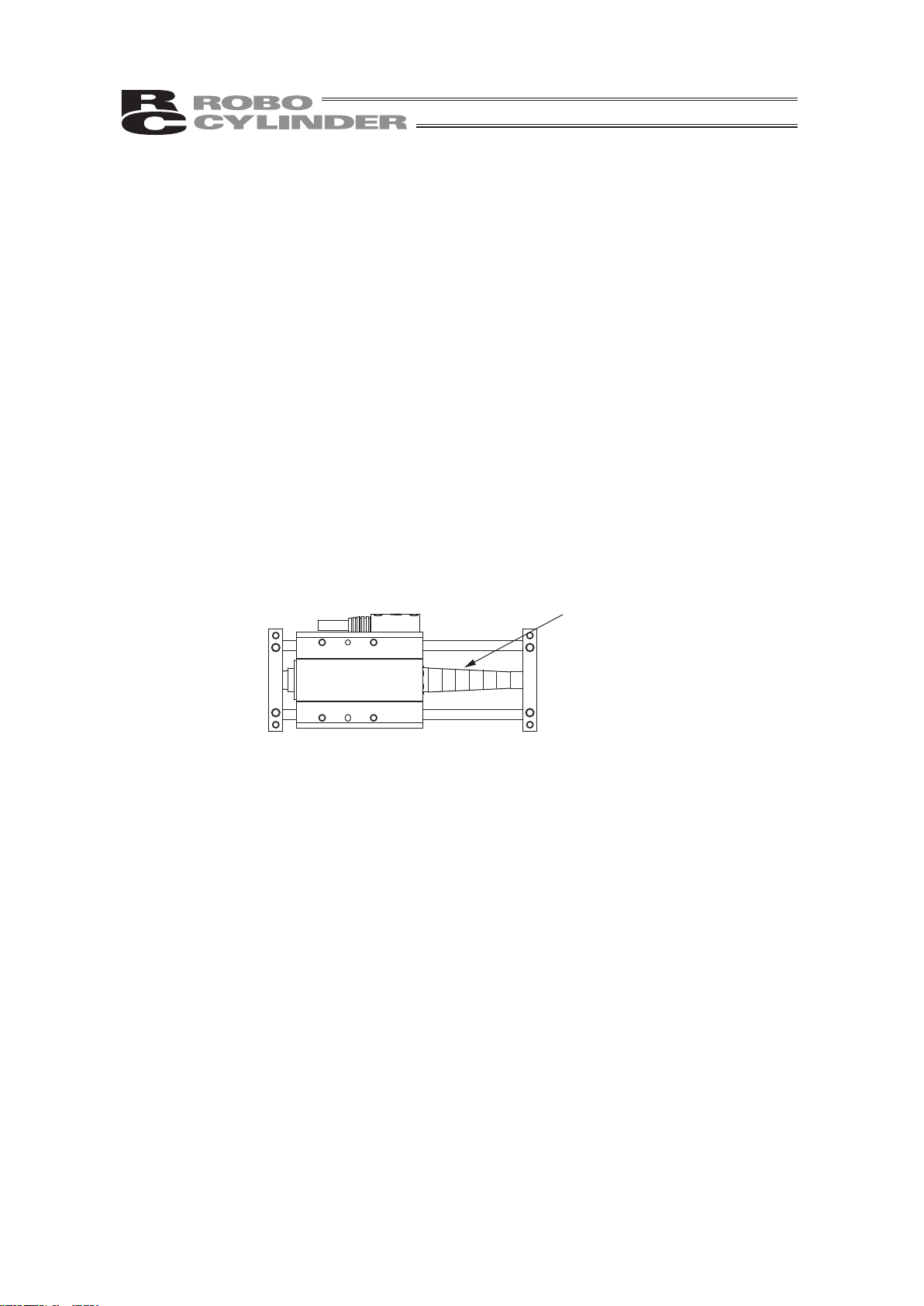
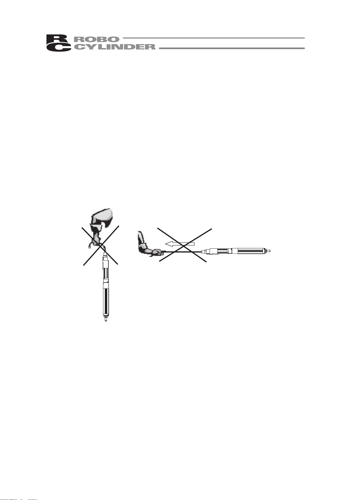
3. Do not apply impact to the spiral cover with tools or push it hard with fingers.
Spiral cover is a thin plate rolled in spiral form. Hitting it with tools or pushing it with fingers may
deform the cover. Do not attempt to do so.
Spiral cover
4. Do not apply any external force to the rod from the directions other than the rod
operating directions.
Please do not apply any external force from other than rod moving direction (radial load) to the rod.
Any perpendicular or radial force to the rod may cause damage to the actuator or operation
problem. Equip an actuator with a guide or an external guide if any external force from other
direction than the rod moving direction is applied.
5. Make sure to attach the actuator properly by following this instruction manual.
Using the product with the actuator not being certainly retained or affixed may cause abnormal
noise, vibration, malfunction or shorten the product life.
Page 17
9
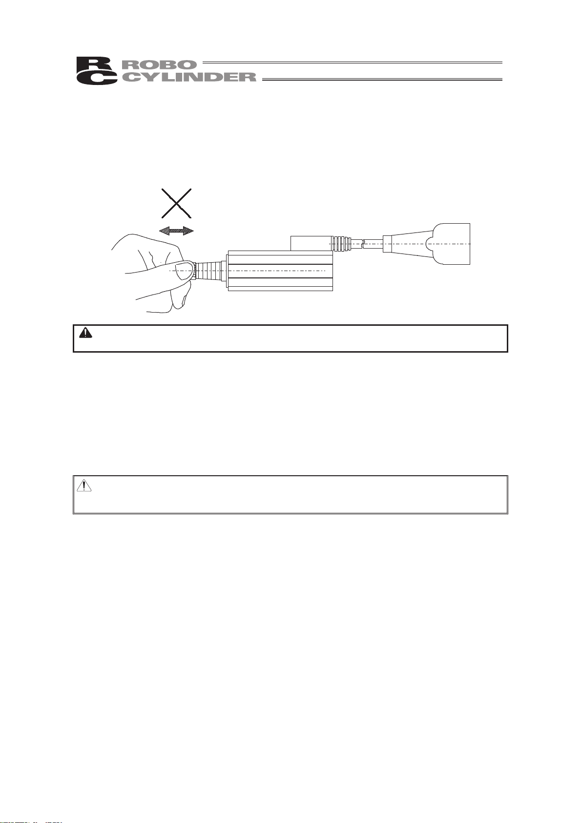
6. For Short Type (RP*N/RN*N), do not attempt to operate the rod back and forth
without the guide.
Operating back and forth from the rod side without the guide would apply unbalanced load to the
feed screw shaft, which may result in a bend of the screw shaft or damage to the internal
mechanism.
Warning : Do not attempt to move the rod back and forth only with the actuator itself.
Unbalanced load onto the feed screw may damage the actuator.
7. Even after attaching the guide, do not move back and forth from the load side
for the low lead types (Lead 1 and 2mm).
The low lead type actuator has a high resistance to the operation from the rod side. Moving it
forcefully would apply too much load to the feed screw and may result in the cause of operational
failure or destruction of the product. Twist the rotation shaft with a screwdriver from the back side to
move the actuator.
Caution : Do not move back and forth from the load side for the low lead types (Lead 1 and 2).
Moving it forcefully would apply too much load to the feed screw and may result in
the cause of operational failure or destruction of the product.
Page 18
10
8. Transportation
8.1 Handling a Single Actuator
Please adhere to the following when handling a single actuator.
8.1.1 Handling the Packed Unit
Unless otherwise specified, the actuator is shipped with each axis packaged separately.
• Do not damage or drop. The package is not applied with any special treatment that enables it to
resist an impact caused by a drop or crash.
• Transport a heavy package with at least more than two operators. Consider an appropriate
method for transportation.
• Keep the unit in horizontal orientation when placing it on the ground or transporting. Follow the
instruction if there is any for the packaging condition.
• Do not step or sit on the package.
• Do not put any load that may cause a deformation or breakage of the package.
8.1.2 Handling the Actuator After Unpacking
• Do not carry an actuator by a cable or attempt to move it by pulling the cable.
• Hold the body base when transporting the actuator.
• Be careful not to bump the actuator into anything when moving it.
• Do not apply an excessive force to each part of the actuator. In particular, prevent the motor unit
and rear bracket from receiving an unnecessary force.
Supplement) For the names of each part of the actuator, refer to 1, "Part Names".
8.2 Handling the Actuator Assembly
• When carrying the actuator, exercise caution not to bump it against nearby objects or structures.
• Secure the sliders to prevent sudden movement during transport.
• If any end of the actuator is overhanging, secure it properly to avoid significant movement due to
external vibration.
• When transporting the assembly without the ends of the actuators fastened, do not subject the
assembly to an impact of 0.3 G or more.
• When suspending the mechanical equipment (system) with ropes, avoid applying force to
actuator, connector box, etc. Also, avoid the cables being pinched or caused an excessive
deformation.
Page 19
11
1. Part Names
The names of the actuator parts are indicated below.
In this manual, the right and left are determined by viewing the actuator from the top and from the
motor side.
1.1 Slim Types
RA2AC (Motor coupling types), RA2AR (Motor reversing types)
Ɣ RA2AC
Opposite side
of the motor
Motor side
Right side
Left side
Motor
Actuator cable
Motor bracket
Rod
Rod tip bracket
Bare housing
Body
Front bracket
* Refer to 2, “External Dimensions” for details.
Ɣ RA2AR
Opposite side
of the motor
Motor side
Right side
Left side
Motor
Actuator cable
Reversing bracket
Rod
Rod tip bracket
Bare housing
Body
Front bracket
Pulley cover
* Refer to 2, “External Dimensions” for details.
1. Part Names
Page 20
1. Part Names
12
1.2 Short Types (Nut Affixing Types)
RN3NA, RN3N (Lead screw, Ball screw), RN4NA, RN4N (Lead screw, Ball
screw)
Opposite side
of the motor
Motor side
Right side
Left side
Connector cover
Cable
Actuator (aluminum frame)
Rod tip bracket
* Refer to 2, “External Dimensions” for details.
1.3 Short Types (Tapped-hole Mounting Types)
RP3NA, RP3N (Lead screw, Ball screw), RP4NA, RP4N (Lead screw, Ball
screw)
Opposite side
of the motor
Motor side
Right side
Left side
Connector cover
Cable
Actuator (aluminum frame)
Rod tip bracket
* Refer to 2, “External Dimensions” for details.
Page 21
13
1.4 Single Guide Types
GS3NA, GS3N (Lead screw, Ball screw), GS4NA, GS4N (Lead screw, Ball
screw)
Opposite side
of the motor
Motor side
Right side
Left side
Connector cover
Cable
Actuator (aluminum frame)
Guide bracket
* Refer to 2, “External Dimensions” for details.
1.5 Double Guide Types
GD3NA, GD3N (Lead screw, Ball screw), GD4NA, GD4N (Lead screw, Ball
screw)
Opposite side
of the motor
Motor side
Right side
Left side
Connector cover
Cable
Actuator (aluminum frame)
Guide bracket
* Refer to 2, “External Dimensions” for details.
1. Part Names
Page 22

14
1.6 Slide Unit Types
SD3NA, SD3N (Lead screw, Ball screw), SD4NA, SD4N (Lead screw, Ball
screw)
Right side
Left side
Connector cover
Cable
Guide bracketGuide bracket
Front side Rear side
* Refer to 2, “External Dimensions” for details.
1. Part Names
Page 23
15
2. External Diagrams
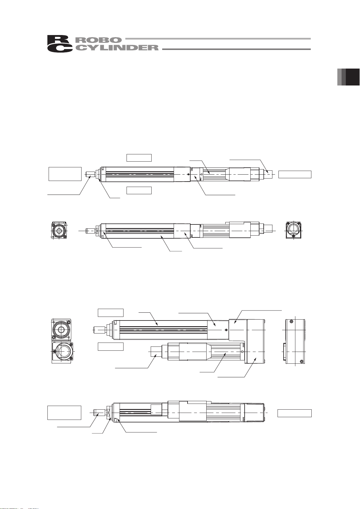
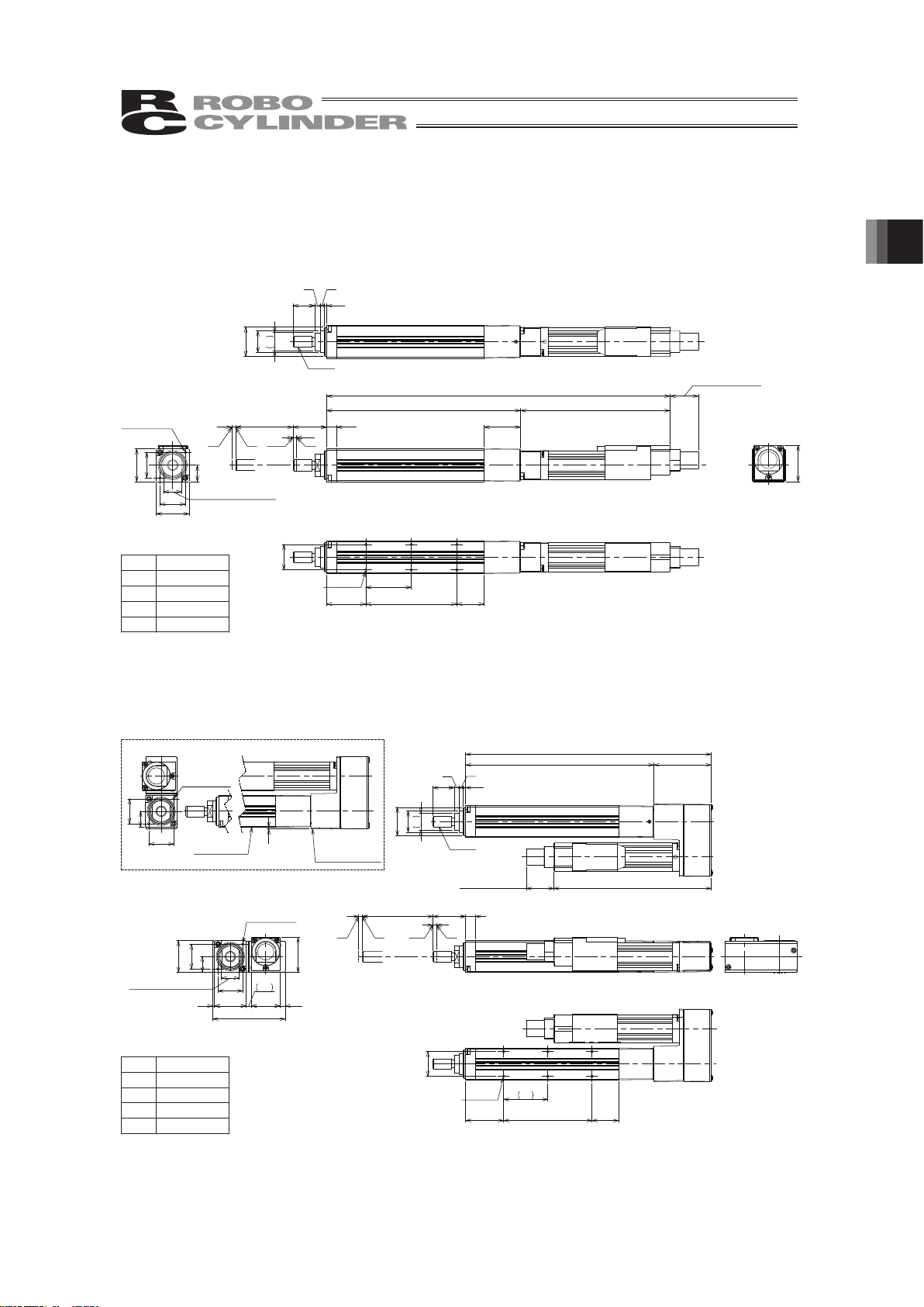
2.1 Slim Type (Motor coupling type) RA2AC
st2
2
L2
5.5 2018.5
82
L1
Secure at least 100
ME
ORG
ME SE
10
φ12φ
16
1.5
2
3
12
M6×1.0
(25)
A×25
14
B-M 2, depth 4
21.5 15
14
14
2-M2, depth 4
10 (between 2 flat faces)
9
18
18
19.8
2.2 Slim Type (Motor reversing type) RA2AR
2
2 st 5.518.5
MEORGSEME
φ16φ
12
10
1.5
2
3
12
Secure at least 100
L1
L2 32.5
89
M6×1.0
18
14
10 (between 2 flat faces)
14
18
9
41
1
2.9
16.2 2.9
19.8
2-M2, depth 4
21.5
25
A×25 15
B-M2, depth 4
14
1
MT type
14
2-M2, depth 4
14
9
Seating surface
Watch for the surface
exceeding from
seating surface
ST Weight [kg]
25 0.17
50 0.19
75 0.2
100 0.22
ST Weight [kg]
25 0.21
50 0.22
75 0.24
100 0.25
2. External Diagrams
Page 24

2. External Diagrams
16
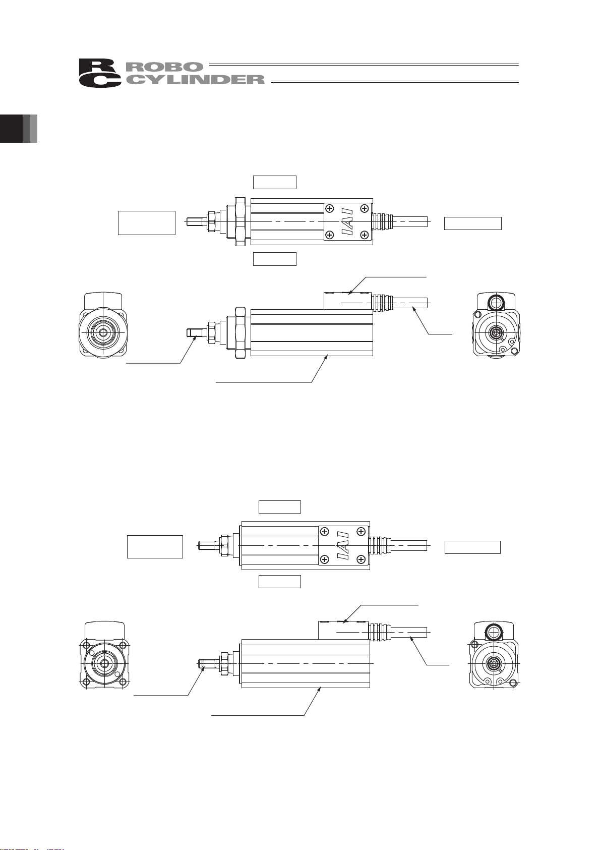
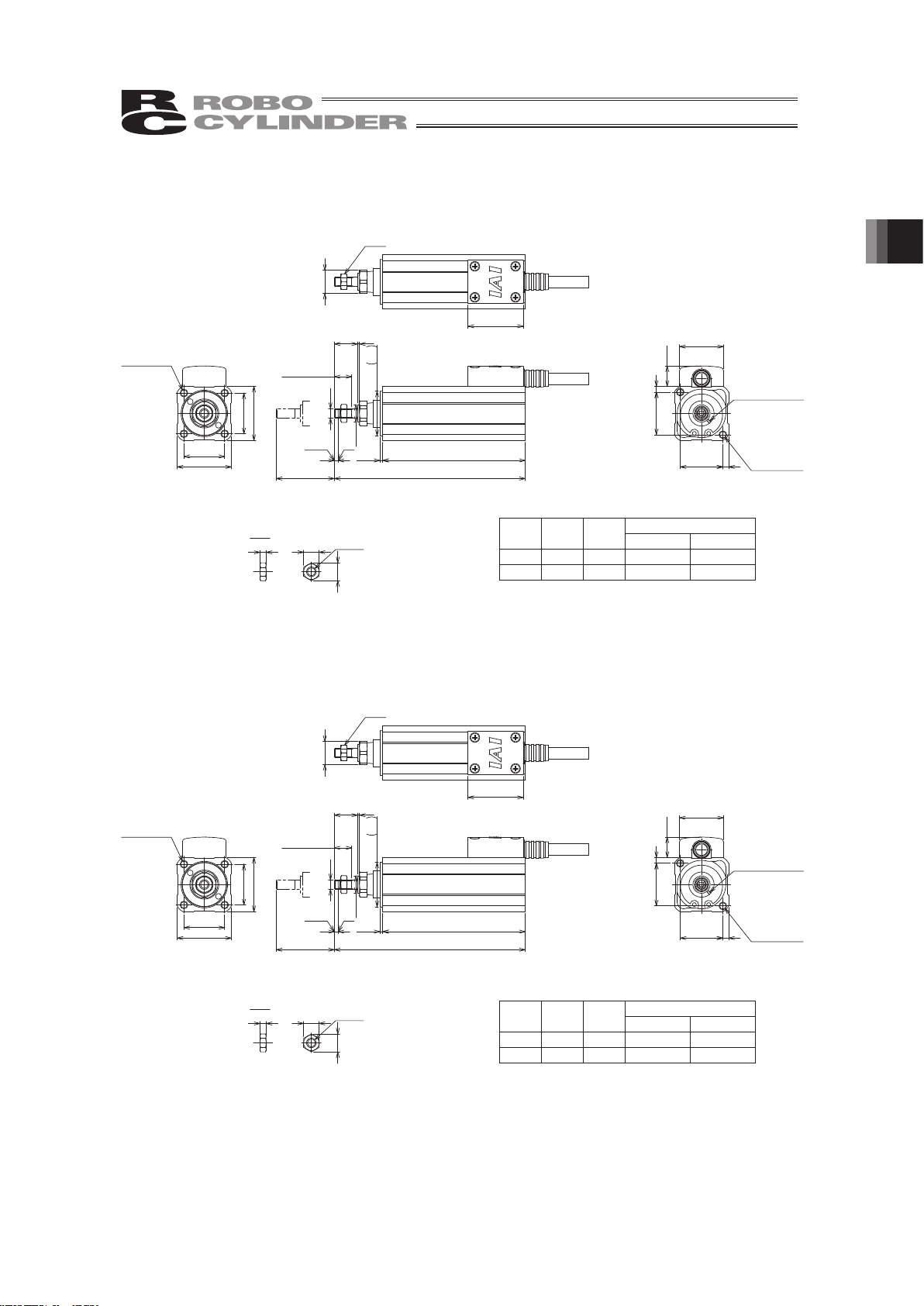
2.3 Short Types (Nut rotating types)
RN3NA, RN3N (Lead screw, Ball screw)
2
ST
L2
L1
M5
12
15
6
9
0
- 0.1
1
ME
10.5
22.6
28
28
22
3
22 3
28.5
M20×1.0
8
(9.2)
M5×0.8
29
φ
30.8
M20×1.0
3.2
6
Nut A
Nut B
Position adjustment
sticker
2-M4, depth 4
Home
29 (Width across flats)
12 (Width
across flats)
9 (Effective
thread length)
Nut A Nut B
2.4 Short Types (Nut rotating types)
RN4NA, RN4N (Lead screw, Ball screw)
2
ST
L217
L1
15 7
M6
Ø 9
0
- 0.1
1
ME
10.5
34
34
22.6
26 4
26 4
28.5
M24×1.0
10
(11.5)
M6×1.0
32
φ
34
M24×1.0
3.6
7
Home
32 (Width across flats)
12 (Width
across flats)
Nut A
Nut B
Position adjustment
sticker
2-M4, depth 8
12 (Effective
thread length)
Nut
A
Nut
B
Weight [kg]
ST L1 L2
Lead screw Ball screw
30 112 73.5 0.25 0.25
50 132 93.5 0.27 0.27
(Note) Only 30mm is available for the stroke of Lead Screw
RN3N Type.
Weight [kg]
ST L1 L2
Lead screw Ball screw
30 123.5 80 0.4 0.4
50 143.5 100 0.44 0.44
(Note) Only 30mm is available for the stroke of Lead Screw
RN4N Type.
Page 25
17
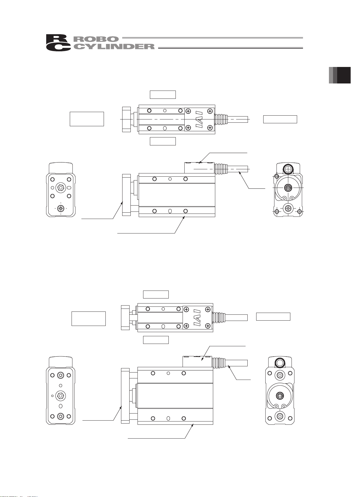
2.5 Short Types (Tapped-hole mounting types)
RP3NA, RP3N (Lead screw, Ball screw)
2
ST
L2
φ
23 h8
0
- 0.033
M5
1.5
L1
12
φ
9
0
- 0.1
1
ME
28.5
28
28
21
21
10.5
22.6
22
22
3
3
8
(9.2)
M5×0.8
3.2
Nut A
Position adjustment
sticker
2-M4, depth 4
Home
9 (Effective
thread length)
4-M4, depth 8
12 (Width across flats)
Nut A
2.6 Short Types (Tapped-hole mounting types)
RP4NA, RP4N (Lead screw, Ball screw)
2
ST
L2
φ
23 h8
0
- 0.033
M5
1.5
L1
12
φ
9
0
- 0.1
1
ME
28.5
28
28
21
21
10.5
22.6
22
22
3
3
8
(9.2)
M5×0.8
3.2
Nut A
Position adjustment
sticker
2-M4, depth 4
Home
9 (Effective
thread length)
4-M4, depth 8
12 (Width across flats)
Nut A
Weight [kg]
ST L1 L2
Lead screw Ball screw
30 98.5 73.5 0.2 0.2
50 118.5 93.5 0.22 0.22
(Note) Only 30mm is available for the stroke of Lead Screw
RP3N Type.
Weight [kg]
ST L1 L2
Lead screw Ball screw
30 108 80 0.32 0.32
50 128 100 0.36 0.36
(Note) Only 30mm is available for the stroke of Lead Screw
RP4N Type.
2. External Diagrams
Page 26
2. External Diagrams
18
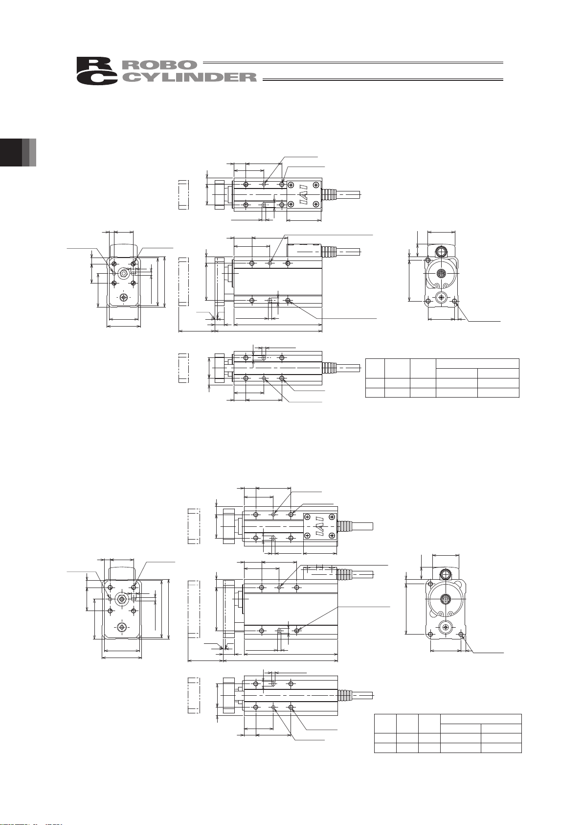
2.7 Single Guide Types
GS3NA, GS3N (Lead screw, Ball screw)
2
4
ST
30
3015
L1
L2
8
2-φ3 depth 3 (same on opposite side)
31 5.5
2-3 depth 3
(same on opposite side)
+0.05
0
ME
10.5
22
34
22.6
3
3
4
40
24
16
16 5
4
28
42
φ
3 depth 3
+0.03
0
3 depth 3
+0.05
0
28
4
30
25
10
17 5.5
28.5
φ
3 depth 3
+0.03
0
3 depth 3
+0.05
0
4
30
25
175.5
10
φ
3 depth 3
+0.03
0
3 depth 3
+0.05
0
4-M4 through
8-M4, depth 4 (*)
(same on opposite side)
3-M4, depth 4
Home
4-M4, depth 4 (*)
+0.03
0
4-M4, depth 6
* Screw-in depths shall not exceed the dimensions shown above.
2.8 Single Guide Types
GS4NA, GS4N (Lead screw, Ball screw)
4
2
ST L1
10 L2
3015
30
2-3 depth 3
(same on opposite side)
+0.05
0
2-φ3 depth 3 (same on opposite side)
+0.03
0
737
ME
10.5
22.6
26
43
4
4
4
30
34
49
51
205
20 6
φ
3 depth 3
+0.03
0
3 depth 3
+0.05
0
34
4
20 7
25
10 30
28.5
φ
3 depth 3
+0.03
0
3 depth 3
+0.05
0
4
3010
25
207
φ
3 depth 3
+0.03
0
3 depth 3
+0.05
0
4-M4, depth 8
4-M4 through
8-M4, depth 5
(same on opposite side)
Home
4-M4, depth 5
3-M4, depth 8
Weight [kg]
ST L1 L2
Lead screw Ball screw
30 89.5 73.5 0.32 0.32
50 109.5 93.5 0.36 0.36
(Note) Only 30mm is available for the stroke of Lead Screw
GS3N Type.
Weight [kg]
ST L1 L2
Lead screw Ball screw
30 98 80 0.55 0.57
50 118 100 0.62 0.63
(Note) Only 30mm is available for the stroke of Lead
Screw GS4N Type.
Page 27
19
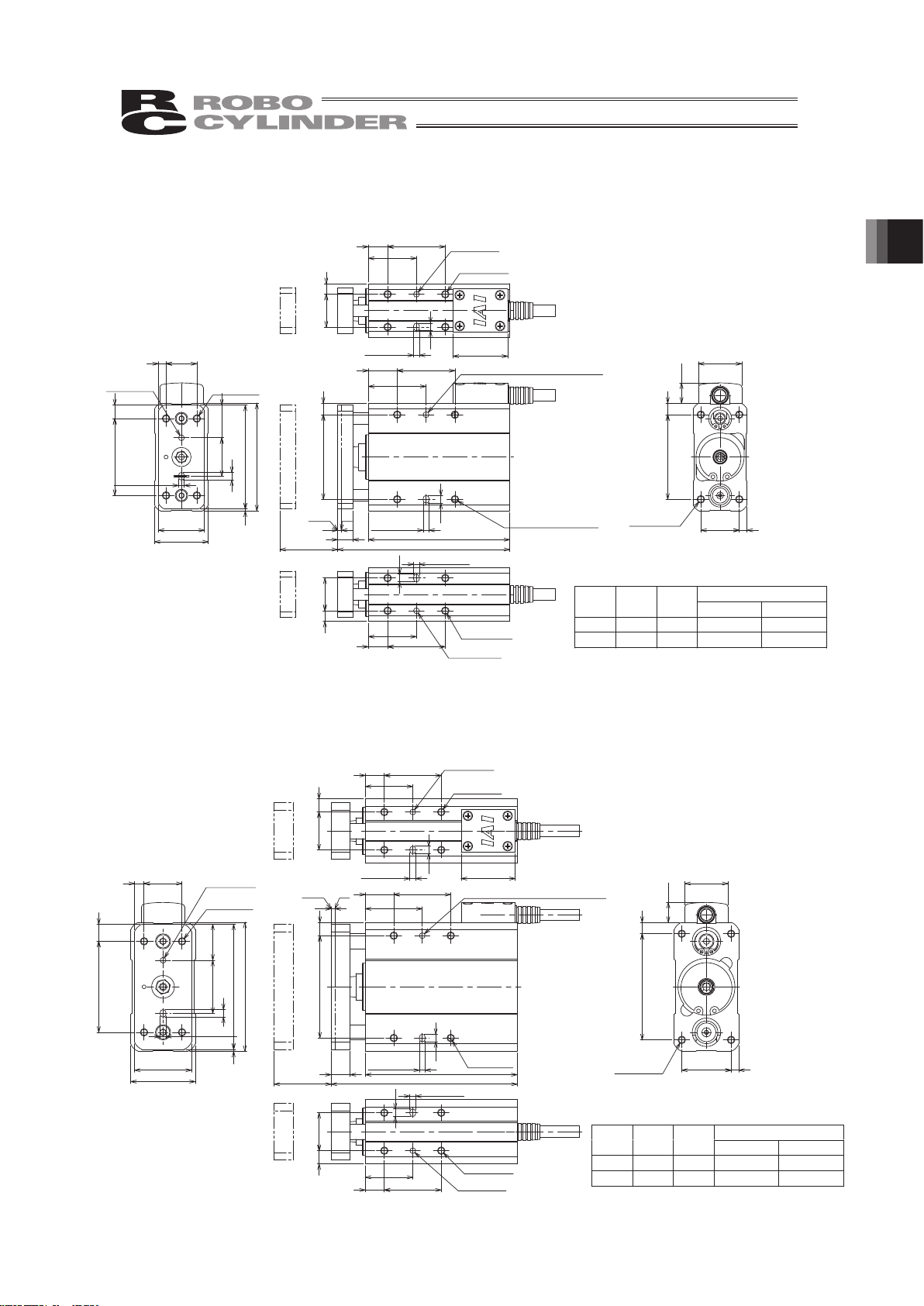
2.9 Double Guide Types
GD3NA, GD3N (Lead screw, Ball screw)
4
2
ST
30
15 30
44 6
L1
8
L2
2-φ3 depth 3 (same on opposite side)
2-3 depth 3
(same on opposite side)
22.6
44 6
20 4
10.5
4
20
1
164
40 7
28
24
56
54
17
3 depth 3
+0.05
0
φ
3 depth 3
+0.03
0
4
25
3010
175.5
3 depth3
φ
3 depth 3
ME
4
3010
25
17 5.5
28.5
φ
3 depth 3
+0.03
0
3 depth 3
+0.05
0
4-M4 through
8-M4, depth6
(same on opposite side)
Home
4-M4, depth 6
4-M4, depth 4
+0.03
0
+0.05
0
+0.05
0
4-M4, depth 6
+0.03
0
2.10 Double Guide Types
GD4NA, GD4N (Lead screw, Ball screw)
Weight [kg]
ST L1 L2
Lead screw Ball screw
30 89.5 73.5 0.41 0.41
50 109.5 93.5 0.48 0.48
(Note) Only 30mm is available for the stroke of Lead Screw
GD3N Type.
4
2
ST
30
54 7
L1
10 L2
30
15
2-3 depth 3
(same on opposite side)
+0.05
0
2-φ3 depth 3 (same on opposite side)
ME
10.5
56 6
22.6
26 4
28
4
1
205
48 9
66
68
30
34
19
φ
3 depth 3
+0.03
0
3 depth 3
4
30
25
207
φ
3 depth 3
+0.03
0
3 depth 3
+0.05
0
10
4
25
3010
20 7
28.5
φ
3 depth 3
+0.03
0
3 depth 3
+0.05
0
4-M4 through
8-M4, depth 8
(same on opposite side)
Home
4-M4, depth 8
4-M4, depth 8
4-M4, depth 8
+0.05
0
+0.03
0
Weight [kg]
ST L1 L2
Lead screw Ball screw
30 98 80 0.64 0.65
50 118 100 0.76 0.76
(Note) Only 30mm is available for the stroke of Lead Screw
GD4N Type.
2. External Diagrams
Page 28
20
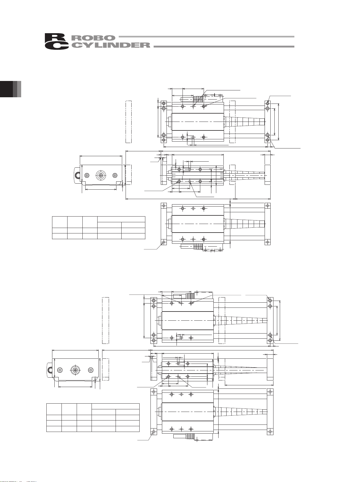
2.11 Slide Unit Types
SD3NA, SD3N (Lead screw, Ball screw)
2.12 Slide Unit Types
SD4NA, SD4N (Lead screw, Ball screw)
-
2
ST
L1 ST
4
L1
8 8 73.5
30
10
25
17
1
3 depth 3
+0.05
0
φ
3 depth 3
+0.03
0
28
8
5.5
ME
4
3015
30
44 6
38
52
L2 4
2-3 depth 3 (same on opposite si de)
+0.05
0
2-φ3 depth 3 (same on opposite si de)
+0.03
0
56
2
2×2-φ3.3
60
29
23.5
1
44
2×2-M4, depth 8
2×4-M4 depth 6
(same on opposite side)
2×2-φ4, H7 depth 5
4-M4, depth 6
Home
D
2
4
ST
ST
20
25
3010
34
10
80810
3 depth 3
+0.05
0
φ
3 depth 3
+0.03
0
7
L1
1
ME
4
L2
5
45
62
54 7
30
3015
2-3 depth 3 (same on opposite side)
+0.05
0
2-φ3 depth 3
(same on opposite side)
+0.03
0
68 2
72
52
29
35
1
2×4-M4, depth 8
(same on opposite side)
4-M4, depth 8
Home
2×2-M5, depth 10
2×2-φ4, H7 depth 5
2×2-φ4.2
Weight [kg]
ST L1 L2
Lead screw Ball screw
25 131 123 0.48 0.48
50 156 146 0.5 0.5
Weight [kg]
ST L1 L2
Lead screw Ball screw
25 141 131 0.71 0.73
50 166 156 0.73 0.75
75 191 181 0.75 0.77
2. External Diagrams
Page 29
21
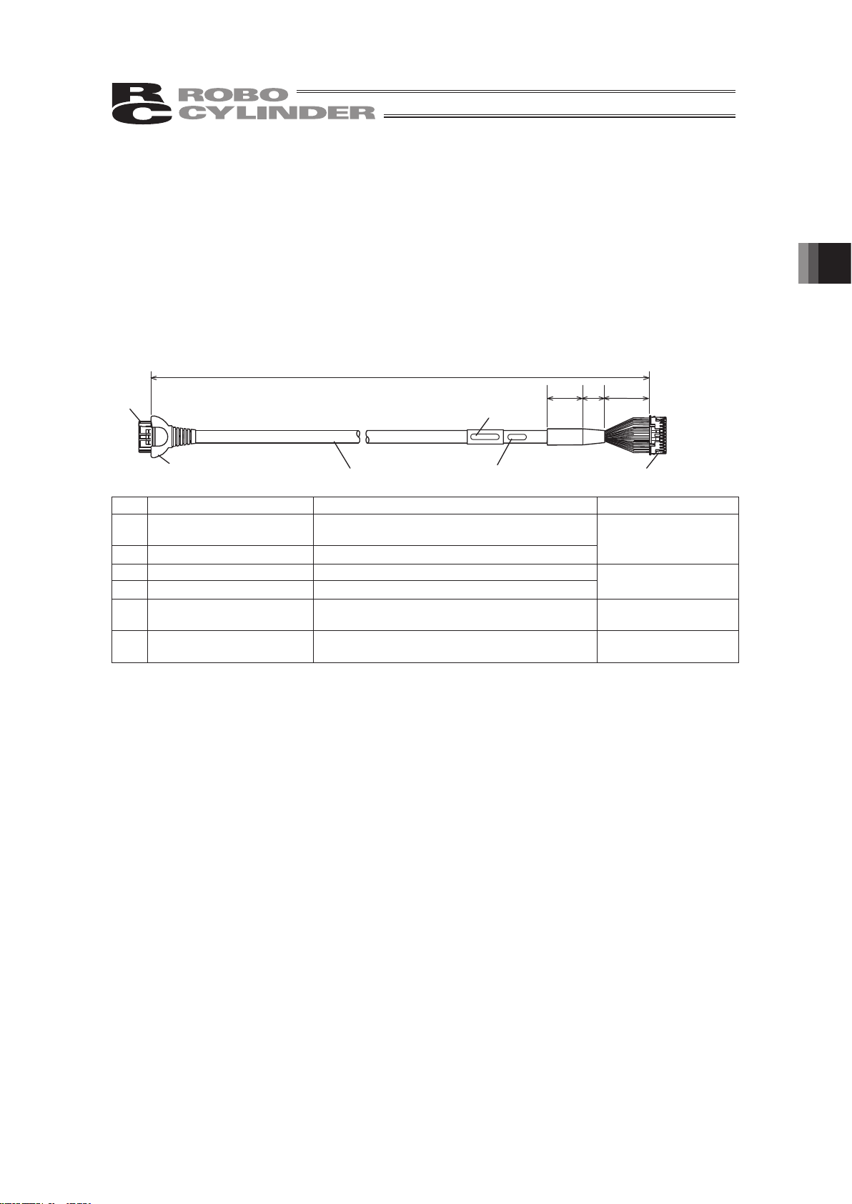
3. Cable Drawings
3.1 ASEP Controller Cables
RCA2 Integrated motor/encoder cable
(CB-APSEP-MPA***)
*** indicates the cable length (L). Up to 10 m can be specified.
Example) 080 = 8 m
Model Nameplate
Lot number
(25)
(15)
(30)
[1][2]
[3][4]
[5] [6]
L
No. Item Model number Manufacturer
1 Housing
D-1100D 1-1827863-1
(black, 2.0-mm pitch, 22 poles)
2 Contact
D-1 1827570-2 (AWG 22 to 18, 1.08 to 1.6 I)
AMP
3 Housing PADP-24V-1-S (white, 2.0-mm pitch, 24 poles)
4 Contact
SPND-001T-C0.5 (AWG 26 to 22, 1.0 to 1.5 I)
JST
5 Coupler cover TMS-4ZB008
TATSUTA ELECTRIC
WIRE & CABLE
6 ZUL2854-OHFRPCVVSW
25AWG x 6P + 25AWG x 2C + 22AWG x 6C,
TS08V0350
TATSUTA ELECTRIC
WIRE & CABLE
3. Cable Drawings
Page 30
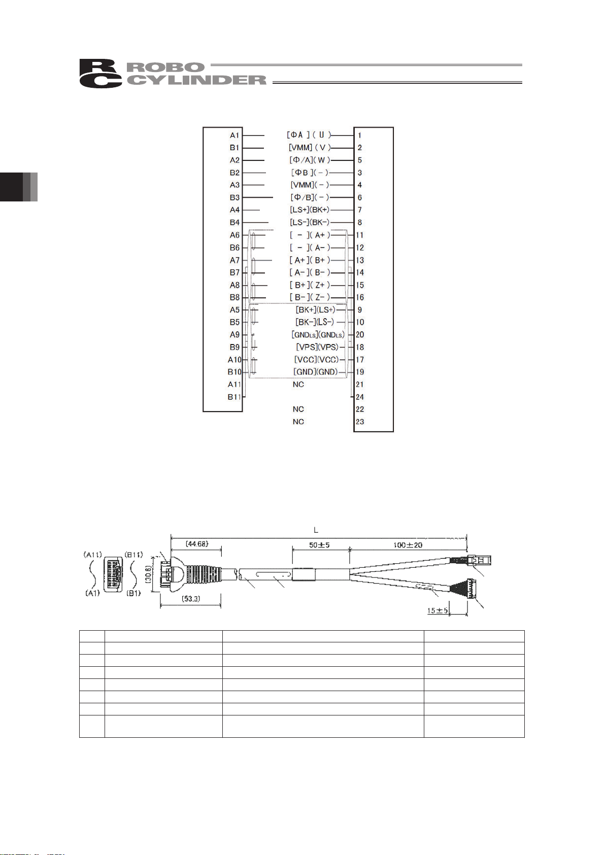
3. Cable Drawings
22
Terminal number
on actuator side
Terminal number
on controller side
Wiring diagram
[PCON] (ACON)
Black
White
Brown
Green
Yellow
Red
Orange
Gray
White
Yellow
Red
Green
Black
Brown
Black
(identification tape)
Shield [FG] (FG)
]3[]1[
Brown
(identification tape)
Green
(identification tape)
Red
(identification tape)
White
(identification tape)
Yellow (ID tape)
3.2 ACON, ASEL Controller Cables
RCA2 Integrated motor/encoder cable
(CB-ACS-MPA***)
*** indicates the cable length (L). Up to 10 m can be specified.
Example) 080 = 8 m
[7]
[1][2]
[7]
[3][4]
[5][6]
Model Nameplate
No. Item Model number Manufacturer
[1] Receptacle housing D-1100D 1-1827863-1 AMP
[2] Receptacle contact D-1 1827570-2 AMP
[3] Socket DF1E-3S-2.5C Hirose
[4] Socket contact DF1E-2022SCF Hirose
[5] Housing PHDR-18VR JST
[6] Contact SPHD-001T-P0.5 JST
[7] UL2854-VVSWKA TS06V1200 (25AWG x 7P + 22AWG x 6C)
TATSUTA ELECTRIC
WIRE & CABLE
Page 31

23
Terminal number
on actuator side
Wiring diagram
[ABZ][Serial]
[3]
[5]
[1]
Black [W] [W]
Red [U] [U]
Pink(Red
)
[
LS+
] [
LS+
]
Orange (Blue/continuous) [/PS] [BAT-]
(Shield) [FG] [FG]
Terminal number
on controller side
Yellow [V] [V]
Pink(Blue
)
[
LS-
] [
LS-
]
White (Red ) [A+] [-]
White (Blue ) [A-] [-]
Orange (Red ) [B+] [-]
Gray (Red ) [Z+] [SD+]
Gray (Blue ) [Z-] [SD-]
Orange (Blue ) [B-] [-]
Orange (Red/continuous) [-] [BAT+]
Gray (Red/continuous) [VCC] [VCC]
Yellow (Red ) [BK+] [BK+]
Yellow (Blue ) [BK-] [BK-]
Gray (Blue/continuous) [GND] [GND]
3. Cable Drawings
Page 32

4. Options
24
4. Options
4.1 Connector Cable Exit Direction Changed
The standard specification is to take out the cable from the opposite side of the rod and guide
bracket. On all models other than the slide unit types SD3N and SD4N, however, you can specify
an option (Model : K2) to reverse the cable take-out direction if you wish to take out the cable from
the rod/guide bracket side due to the layout of the system, etc.
4.2 Low Power Consumption Type
This type of actuator decreases the maximum current consumption of the controller compared with
the standard actuator.
For the details, refer to the power capacity described in the catalog or the instruction manuals of
ACON/ASEL/ASEP/AMEC Controllers. The applicable model number for this option is “LA”.
Model Name
Standard specification /
High acceleration/deceleration
specification
Maximum load current
Energy-saving measure
Maximum load current
RN3NA, RP3NA, GS3NA,
GD3NA, SD3NA, RN3N,
RP3N, GS3N, GD3N, SD3N
4.4A 2.
5A
RN4NA, RP4NA, GS4NA,
GD4NA, SD4NA, RN4N,
RP4N, GS4N, GD4N, SD4N
4.4A 2.
5A
Page 33

25
5. Checking after Unpacking
After unpacking, check the condition of the product and the included items.
5.1 Included Items
No. Item Remarks
1 Actuator
Refer to “How to Read Model Nameplate” and
“How to Read Model”.
Accessories
CB-APSEP-MPAƑƑƑ: ASEP type
2 RCA integrated motor/encoder cable
CB-ACS-MPAƑƑƑ: ACON, ASEL type
3 First Step Guide
4 Instruction Manual (CD/DVD)
5 Safety Guide
5.2 Instruction Manuals Relating to This Product
No. Name Manual No.
1 Instruction Manual for ASEL Controller ME0165
2 Instruction Manual for ACON-C/CG Controller ME0176
3 Instruction Manual for ACON-CY Controller ME0167
4 Instruction Manual for ACON-SE Controller ME0171
5 Instruction Manual for ACON-PL/PO Controller ME0166
6 Instruction Manual for AMEC Controller ME0245
7 Instruction Manual for ASEP/PSEP Controller ME0216
8 Instruction Manual for PC Software IA-101-X-MX/IA-101-X-USBMW ME0154
9 Instruction Manual for PC Software RCM-101MW/RCM-101-USB ME0155
10 Instruction Manual for MEC PC Software ME0248
11 Instruction Manual for Teaching Pendant SEL-T/TD ME0183
12 Instruction Manual for Teaching Pendant CON-T/TG ME0178
13 Instruction Manual for Touch Panel Teaching CON-PT/PD/PG ME0227
14 Instruction Manual for Touch Panel Teaching SEP-PT ME0217
15 Instruction Manual for Simple Teaching Pendant RCM-E ME0174
16 Instruction Manual for Data Setter RCM-P ME0175
17 Instruction Manual for Data Setter RCM-PM-01 ME0182
5. Checking after Unpacking
Page 34

26
5.3 How to Read Model Nameplate
Model
Serial number
5.4 How to Read Model
RCA2
- RN3N – I – 10 – 4 – 30 - A1 – P – FL – **
*1 This may be displayed for the manufacturing reason.
(This is not to indicate the manufacturing model code.)
<Series name>
<Type>
Slim types
RA2AC (Motor coupling types)
RA2AR (Motor reversing types)
Short types
(Nut affixing types)
RN3NA, RN3N
RN4NA, RN4N
Short types
(Tapped-hole mounting types)
RP3NA, RP3N
RP4NA, RP4N
Single guide types
GS3NA, GS3N
GS4NA, GS4N
Double guide types
GD3NA, GD3N
GD4NA, GD4N
Slide unit types
SD3NA, SD3N
SD4NA, SD4N
<Encoder type>
I: Incremental
<Motor type>
5 (5W) : RA2AC, RA2AR
10 (10 W) : RN3NA, RP3NA, GS3NA,
GD3NA, SD3NA,
RN3N, RP3N, GS3N,
GD3N, SD3N
20 (20 W) : RN4NA, RP4NA, GS4NA,
GD4NA, SD4NA,
RN4N, RP4N, GS4N,
GD4N, SD4N
Identification for IAI use only
*1
<Option>
A2 : Connector cable exit direction
changed
LA : Low power consumption type
<Cable length>
N : None
P : 1m
S : 3m
M : 5m
X�
� : Specified length
<Applicable controller>
A1 : ASEL
ACON-C/CG
ACON-CY
ACON-SE
ACON-PL/PO
A3 : AMEC
ASEP
<Stroke>
<Lead>
RA2AC, RA2AR
1/2/4
RN3NA, RP3NA, GS3NA, GD3NA,
SD3NA, RN3N, RP3N, GS3N, GD3N
SD3N (Slide screw)
1S/2S/4S
RN3NA, RP3NA, GS3NA, GD3NA,
SD3NA, RN3N, RP3N, GS3N, GD3N
SD3N (Ball screw)
1/2/4
RN4NA, RP4NA, GS4NA, GD4NA,
SD4NA, RN4N, RP4N, GS4N, GD4N
SD4N (Slide screw)
2S/4S/6S
RN4NA, RP4NA, GS4NA, GD4NA,
SD4NA, RN4N, RP4N, GS4N, GD4N
SD4N (Ball screw)
2/4/6
5. Checking after Unpacking
Page 35

27
6. Specifications
(1) Maximum speed
The maximum speed of this ROBO Cylinder is limited to prevent resonance of the ball screw shaft
and also due to limitation of the motor speed. Observe the maximum speed limits specified in the
table.
Strokes and Maximum Speed Limits [Unit: mm/s]
Stroke [mm]
Model Motor Type Lead [mm]
25 30 50 75 100
1 50 - 50
2 100 - 100
RA2AC 5W
4 180 - 200
1 50 - 50
2 100 - 100
RA2AR 5W
4 180 - 200
1
㧙
50
㧙 㧙 㧙
2
㧙
100
㧙 㧙 㧙
RN3NA
(Lead screw)
10W
4
㧙
200
㧙 㧙 㧙
1
㧙
50 50
㧙 㧙
2
㧙
100 100
㧙 㧙
RN3NA
(Ball screw)
10W
4
㧙
200 200
㧙 㧙
2
㧙
100
㧙 㧙 㧙
4
㧙
200
㧙 㧙 㧙
RN4NA
(Lead screw)
20W
6
㧙
220
㧙 㧙 㧙
2
㧙
100 100
㧙 㧙
4
㧙
200 200
㧙 㧙
RN4NA
(Ball screw)
20W
6
㧙
270<220> 300
㧙 㧙
1
㧙
50
㧙 㧙 㧙
2
㧙
100
㧙 㧙 㧙
RP3NA
(Lead screw)
10W
4
㧙
200
㧙 㧙 㧙
1
㧙
50 50
㧙 㧙
2
㧙
100 100
㧙 㧙
RP3NA
(Ball screw)
10W
4
㧙
200 200
㧙 㧙
2
㧙
100
㧙 㧙 㧙
4
㧙
200
㧙 㧙 㧙
PR4NA
(Lead screw)
20W
6
㧙
220
㧙 㧙 㧙
2
㧙
100 100
㧙 㧙
4
㧙
200 200
㧙 㧙
RP4NA
(Ball screw)
20W
6
㧙
270<220> 300
㧙 㧙
1
㧙
50
㧙 㧙 㧙
2
㧙
100
㧙 㧙 㧙
GS3NA
(Lead screw)
10W
4
㧙
200
㧙 㧙 㧙
1
㧙
50 50
㧙 㧙
2
㧙
100 100
㧙 㧙
GS3NA
(Ball screw)
10W
4
㧙
200 200
㧙 㧙
2
㧙
100
㧙 㧙 㧙
4
㧙
200
㧙 㧙 㧙
GS4NA
(Lead screw)
20W
6
㧙
220
㧙 㧙 㧙
2
㧙
100 100
㧙 㧙
4
㧙
200 200
㧙 㧙
GS4NA
(Ball screw)
20W
6
㧙
270<220> 300
㧙 㧙
1
㧙
50
㧙 㧙 㧙
2
㧙
100
㧙 㧙 㧙
GD3NA
(Lead screw)
10W
4
㧙
200
㧙 㧙 㧙
(Note) The maximum speed may not be reached depending on the acceleration/deceleration setting.
Values in < > are for when mounted vertically.
6. Specications
Page 36

6. Specications
28
Stroke [mm]
Model Motor Type Lead [mm]
25 30 50 75 100
1
㧙
50 50
㧙 㧙
2
㧙
100 100
㧙 㧙
GD3NA
(Ball screw)
10W
4
㧙
200 200
㧙 㧙
2
㧙
100
㧙 㧙 㧙
4
㧙
200
㧙 㧙 㧙
GD4NA
(Lead screw)
20W
6
㧙
220
㧙 㧙 㧙
2
㧙
100 100
㧙 㧙
4 - 200 200 - -
GD4NA
(Ball screw)
20W
6 -
270<220>
300 - 1 - 50 - - 2 - 100 - - -
RN3N
(Lead screw)
10W
4 - 2
00 - - 1 - 50 - - 2 - 100 - - -
RN3N
(Ball screw)
10W
4 - 2
00 - - 2 - 100 - - 4 - 200 - - -
RN4N
(Lead screw)
20W
6 - 220 - - 2 - 100 - - 4 - 200 - - -
RN4N
(Ball screw)
20W
6 -
270<220> - - 1 - 50 - - 2 - 100 - - -
RP3N
(Lead screw)
10W
4 - 2
00 - - 1 - 50 - - 2 - 100 - - -
RP3N
(Ball screw)
10W
4 - 2
00 - - 2 - 100 - - 4 - 200 - - -
RP4N
(Lead screw)
20W
6 - 2
20 - - 2 - 100 - - 4 - 200 - - -
RP4N
(Ball screw)
20W
6 -
270<220> - - 1 - 50 - - 2 - 100 - - -
GS3N
(Lead screw)
10W
4 - 2
00 - - 1 - 50 - - 2 - 100 - - -
GS3N
(Ball screw)
10W
4 - 2
00 - - 2 - 100 - - 4 - 200 - - -
GS4N
(Lead screw)
20W
6 - 2
20 - - 2 - 100 - - 4 - 200 - - -
GS4N
(Ball screw)
20W
6 -
270<220> - - 1 - 50 - - 2 - 100 - - -
GD3N
(Lead screw)
10W
4 - 2
00 - - 1 - 50 - - 2 - 100 - - -
GD3N
(Ball screw)
10W
4 - 200 - - -
(Note) The maximum speed may not be reached depending on the acceleration/deceleration setting.
Values in < > are for when mounted vertically.
Page 37

29
Stroke [mm]
Model Motor Type Lead [mm]
25 30 50 75 100
2 - 100 - - 4 - 200 - - -
GD4N
(Lead screw)
20W
6 - 2
20 - - 2 - 100 - - 4 - 200 - - -
GD4N
(Ball screw)
20W
6 -
270<220> - - 1 50 - 50 - 2 100 - 100 - -
SD3NA
SD3N
(Lead screw)
10W
4 20
0 - 200 - 1 50 - 50 - 2 100 - 100 - -
SD3NA
SD3N
(Ball screw)
10W
4 200 - 200 - 2 100 - 100 100 4 200 - 200 200 -
SD4NA
SD4N
(Lead screw)
20W
6 200 - 300 300 2 100 - 100 100 4 200 - 200 200 -
SD4NA
SD4N
(Ball screw)
20W
6 240<200> - 300 300 -
(Note) The maximum speed may not be reached depending on the acceleration/deceleration setting.
Values in < > are for when mounted vertically.
Caution : Do not set a speed or acceleration/deceleration exceeding the applicable rating.
Doing so may result in vibration, failure or shorter life.
Setting the acceleration/deceleration exceeding the applicable rating may also cause
creep.
6. Specications
Page 38

6. Specications
30
(2) Acceleration and payloads
Model Motor Type Lead [mm]
Rated acceleration
[G]
Payload
[kg]
Horizontal 0.3 2
1
Vertical 0.
3 1
Horizontal 0.3 1
2
Vertical 0.
3 0.5
Horizontal 0.3 0.5
RA2AC 5W
4
Vertical 0.
3 0.25
Horizontal 0.3 2
1
Vertical 0.
3 1
Horizontal 0.3 1
2
Vertical 0.
3 0.5
Horizontal 0.3 0.5
RA2AR 5W
4
Vertical 0.
3 0.25
Horizontal 0.2 1
1
Vertical 0.
2 0.5
Horizontal 0.2 0.5
2
Vertical 0.
2 0.25
Horizontal 0.2 0.25
RN3NA
RN3N
(Lead screw)
10W
4
Vertical 0.
2 0.125
Horizontal 0.2 3
1
Vertical 0.
2 1
Horizontal 0.3 1.5
2
Vertical 0.
2 0.5
Horizontal 0.3 0.75
RN3NA
RN3N
(Ball screw)
10W
4
Vertical 0.
2 0.25
Horizontal 0.2 1
2
Vertical 0.
2 0.5
Horizontal 0.2 0.5
4
Vertical 0.
2 0.25
Horizontal 0.2 0.25
RN4NA
RN4N
(Lead screw)
20W
6
Vertical 0.
2 0.125
Horizontal 0.2 6
2
Vertical 0.
2 1.5
Horizontal 0.3 3
4
Vertical 0.
2 0.75
Horizontal 0.3 2
RN4NA
RN4N
(Ball screw)
20W
6
Vertical 0.
2 0.5
(Note) Maximum speed may not be reached on all strokes.
The maximum speed of each model with a longer stroke will be less than the applicable maximum
speed shown in the table.
[Refer to (1), “Maximum speed”.]
Page 39

31
Model Motor Type Lead [mm]
Rated acceleration
[G]
Payload
[kg]
Horizontal 0.2 1
1
Vertical 0.
2 0.5
Horizontal 0.2 0.5
2
Vertical 0.
2 0.25
Horizontal 0.2 0.25
RP3NA
RP3N
(Lead screw)
10W
4
Vertical 0.
2 0.125
Horizontal 0.2 3
1
Vertical 0.
2 1
Horizontal 0.3 1.5
2
Vertical 0.
2 0.5
Horizontal 0.3 0.75
RP3NA
RP3N
(Ball screw)
10W
4
Vertical 0.
2 0.25
Horizontal 0.2 1
2
Vertical 0.
2 0.5
Horizontal 0.2 0.5
4
Vertical 0.
2 0.25
Horizontal 0.2 0.25
RP4NA
RP4N
(Lead screw)
20W
6
Vertical 0.
2 0.125
Horizontal 0.2 6
2
Vertical 0.
2 1.5
Horizontal 0.3 3
4
Vertical 0.
2 0.75
Horizontal 0.3 2
RP4NA
RP4N
(Ball screw)
20W
6
Vertical 0.
2 0.5
Horizontal 0.2 1
1
Vertical 0.
2 0.5
Horizontal 0.2 0.5
2
Vertical 0.
2 0.25
Horizontal 0.2 0.25
GS3NA
GS3N
(Lead screw)
10W
4
Vertical 0.
2 0.125
Horizontal 0.2 3
1
Vertical 0.
2 1
Horizontal 0.3 1.5
2
Vertical 0.
2 0.5
Horizontal 0.3 0.75
GS3NA
GS3N
(Ball screw)
10W
4
Vertical 0.
2 0.25
Horizontal 0.2 1
2
Vertical 0.
2 0.5
Horizontal 0.2 0.5
4
Vertical 0.
2 0.25
Horizontal 0.2 0.25
GS4NA
GS4N
(Lead screw)
20W
6
Vertical 0.
2 0.125
Horizontal 0.2 6
2
Vertical 0.
2 1.5
Horizontal 0.3 3
4
Vertical 0.
2 0.75
Horizontal 0.3 2
GS4NA
GS4N
(Ball screw)
20W
6
Vertical 0.
2 0.5
(Note) Maximum speed may not be reached on all strokes.
The maximum speed of each model with a longer stroke will be less than the applicable maximum
speed shown in the table.
[Refer to (1), “Maximum speed”.]
6. Specications
Page 40

6. Specications
32
Model Motor Type Lead [mm]
Rated acceleration
[G]
Payload
[kg]
Horizontal 0.2 1
1
Vertical 0.
2 0.5
Horizontal 0.2 0.5
2
Vertical 0.
2 0.25
Horizontal 0.2 0.25
GD3NA
GD3N
(Lead screw)
10W
4
Vertical 0.
2 0.125
Horizontal 0.2 3
1
Vertical 0.
2 1
Horizontal 0.3 1.5
2
Vertical 0.
2 0.5
Horizontal 0.3 0.75
GD3NA
GD3N
(Ball screw)
10W
4
Vertical 0.
2 0.25
Horizontal 0.2 1
2
Vertical 0.
2 0.5
Horizontal 0.2 0.5
4
Vertical 0.
2 0.25
Horizontal 0.2 0.25
GD4NA
GD4N
(Lead screw)
20W
6
Vertical 0.
2 0.125
Horizontal 0.2 6
2
Vertical 0.
2 1.5
Horizontal 0.3 3
4
Vertical 0.
2 0.75
Horizontal 0.3 2
GD4NA
GD4N
(Ball screw)
20W
6
Vertical 0.
2 0.5
Horizontal 0.2 1
1
Vertical 0.
2 0.5
Horizontal 0.2 0.5
2
Vertical 0.
2 0.25
Horizontal 0.2 0.25
SD3NA
SD3N
(Lead screw)
10W
4
Vertical 0.
2 0.125
Horizontal 0.2 3
1
Vertical 0.
2 1
Horizontal 0.3 1.5
2
Vertical 0.
2 0.5
Horizontal 0.3 0.75
SD3NA
SD3N
(Ball screw)
10W
4
Vertical 0.
2 0.25
Horizontal 0.2 1
2
Vertical 0.
2 0.5
Horizontal 0.2 0.5
4
Vertical 0.
2 0.25
Horizontal 0.2 0.25
SD4NA
SD4N
(Lead screw)
20W
6
Vertical 0.
2 0.125
Horizontal 0.2 6
2
Vertical 0.
2 1.5
Horizontal 0.3 3
4
Vertical 0.
2 0.75
Horizontal 0.3 2
SD4NA
SD4N
(Ball screw)
20W
6
Vertical 0.
2 0.5
(Note) Maximum speed may not be reached on all strokes.
The maximum speed of each model with a longer stroke will be less than the applicable maximum
speed shown in the table.
[Refer to (1), “Maximum speed”.]
Page 41

33
(3) Rated thrust
Model Motor Type Lead [mm]
Rated thrust
[N]
Model Motor Type Lead [mm]
Rated thrust
[N]
1 85.5 1 100.5
2 42.3 2 50.3
RA2AC 5W
4 21.4
GS3NA
GS3N
(Lead screw)
10W
4 25.1
1 85.5 1 170.9
2 42.3 2 85.5
RA2AR 5W
4 21.4
GS3NA
GS3N
(Ball screw)
10W
4 42.7
1 100.5 2 59.7
2 50.3 4 29.8
RN3NA
RN3N
(Lead screw)
10W
4 25.1
GS4NA
GS4N
(Lead screw)
20W
6 19.9
1 170.9 2 101.5
2 85.5 4 50.7
RN3NA
RN3N
(Ball screw)
10W
4 42.7
GS4NA
GS4N
(Ball screw)
20W
6 33.8
2 59.7 1 100.5
4 29.8 2 50.3
RN4NA
RN4N
(Lead screw)
20W
6 19.9
GD3NA
GD3N
(Lead screw)
10W
4 25.1
2 101.5 1 170.9
4 50.7 2 85.5
RN4NA
RN4N
(Ball screw)
20W
6 33.8
GD3NA
GD3N
(Ball screw)
10W
4 42.7
1 100.5 2 59.7
2 50.3 4 29.8
RP3NA
RP3N
(Lead screw)
10W
4 25.1
GD4NA
GD4N
(Lead screw)
20W
6 19.9
1 170.9 2 101.5
2 85.5 4 50.7
RP3NA
RP3N
(Ball screw)
10W
4 42.7
GD4NA
GD4N
(Ball screw)
20W
6 33.8
2 59.7 1 100.5
4 29.8 2 50.3
RP4NA
RP4N
(Lead screw)
20W
6 19.9
SD3NA
SD3N
(Lead screw)
10W
4 25.1
2 101.5 1 170.9
4 50.7 2 85.5
RP4NA
RP4N
(Ball screw)
20W
6 33.8
SD3NA
SD3N
(Ball screw)
10W
4 42.7
2 59.7
4 29.8
SD4NA
SD4N
(Lead screw)
20W
6 19.9
2 101.5
4 50.7
SD4NA
SD4N
(Ball screw)
20W
6 33.8
6. Specications
Page 42

6. Specications
34
(4) Drive method
Model Motor Type Lead Encoder pulses*1 Drive method
1
2
RA2AC 5W
4
Ball screw
I4mm
Rolled, C10
1
2
RA2AR 10W
4
800
Ball screw
I6mm
Rolled, C10
1
2
RN3NA
RN3N
(Lead screw)
10W
4
Lead screw
I4mm
Rolled, C10
1
2
RN3NA
RN3N
(Ball screw)
10W
4
Ball screw
I4mm
Rolled, C10
2
4
RN4NA
RN4N
(Lead screw)
20W
6
Lead screw
I6mm
Rolled, C10
2
4
RN4NA
RN4N
(Ball screw)
20W
6
Ball screw
I6mm
Rolled, C10
1
2
RP3NA
RP3N
(Lead screw)
10W
4
Lead screw
I4mm
Rolled, C10
1
2
RP3NA
RP3N
(Ball screw)
10W
4
Ball screw
I4mm
Rolled, C10
2
4
RP4NA
RP4N
(Lead screw)
20W
6
Lead screw
I6mm
Rolled, C10
2
4
RP4NA
RP4N
(Ball screw)
20W
6
Ball screw
I6mm
Rolled, C10
1
2
GS3NA
GS3N
(Lead screw)
10W
4
Lead screw
I4mm
Rolled, C10
1
2
GS3NA
GS3N
(Ball screw)
10W
4
Ball screw
I4mm
Rolled, C10
2
4
GS4NA
GS4N
(Lead screw)
20W
6
Lead screw
I6mm
Rolled, C10
2
4
GS4NA
GS4N
(Ball screw)
20W
6
Ball screw
I6mm
Rolled, C10
1
2
GD3NA
GD3N
(Lead screw)
10W
4
Lead screw
I4mm
Rolled, C10
1
2
GD3NA
GD3N
(Ball screw)
10W
4
Ball screw
I4mm
Rolled, C10
2
4
GD4NA
GD4N
(Lead screw)
20W
6
Lead screw
I6mm
Rolled, C10
2
4
GD4NA
GD4N
(Ball screw)
20W
6
1048
Ball screw
I6mm
Rolled, C10
*1 Number of pulses input to the controller.
Page 43

35
Model Motor Type Lead Encoder pulses*1 Drive method
1
2
SD3NA
SD3N
(Lead screw)
10W
4
Lead screw
I4mm
Rolled, C10
1
2
SD3NA
SD3N
(Ball screw)
10W
4
Ball screw
I4mm
Rolled, C10
2
4
SD4NA
SD4N
(Lead screw)
20W
6
Lead screw
I6mm
Rolled, C10
2
4
SD4NA
SD4N
(Ball screw)
20W
6
1048
Ball screw
I6mm
Rolled, C10
*1 Number of pulses input to the controller.
(5) Common specifications
Specification
Item
Lead screw Ba
ll screw
Positioning repeatability*1 ±0.05mm ±0.02mm
Backlash*1 0.3mm or less 0.1mm or less
Base Material: Aluminum with special alumite treatment
* Default value
6. Specications
Page 44

7. Installation and Storage/Preservation Environment
36
7. Installation and Storage/Preservation Environment
7.1 Installation Environment
Do not use this product in the following environment
It is generally the environment where a worker can work without any protection gear.
Also make sure to keep enough work space necessary for maintenance.
• Location exposed to radiant heat from a huge heat source such as the heat treatment
• Location where the surrounding air temperature exceeds the range of 0 to 40qC
• Location where condensation occurs due to abrupt temperature changes
• Location where relative humidity exceeds 85%RH
• Location exposed to direct sunlight
• Location exposed to corrosive gases or combustible gases
• Location exposed to significant amount of dust, salt or iron powder (Outside of ordinary assembly
plant)
• Location where water, oil (includes oil mist and cutting fluid) or chemical is splashed
• Location where the product main body receives vibration or hit impact
When using the product in any of the locations specified below, provide a sufficient shield.
• Location subject to electrostatic noise
• Location where exposed to the influence of strong electric or magnetic field
• Location where exposed to the influence of ultraviolet or radiant rays
Open space required for maintenance inspection
Ɣ Motor coupling types
250mm or more
Ɣ Motor reversing types
250mm or more
300mm or more
Page 45

37
7.2 Storage/Preservation Environment
The storage and preservation environment should comply with the same standards as those for the
installation environment. In particular, when the machine is to be stored for a long time, pay close
attention to environmental conditions so that no dew condensation forms.
Unless specially specified, moisture absorbency protection is not included in the package when the
machine is delivered. In the case that the machine is to be stored and preserved in an environment
where dew condensation is anticipated, take the condensation preventive measures from outside
of the entire package, or directly after opening the package.
For storage and preservation temperature, the machine withstands temperatures up to 60qC for a
short time, but in the case of the storage and preservation period of 1 month or more, control the
temperature to 50qC or less.
Storage and preservation should be performed in the horizontal condition. In the case it is stored in
the packaged condition, follow the posture instruction if any displayed on the package.
7. Installation and Storage/Preservation Environment
Page 46

8. Installation
38
8. Installation
8.1 Slim Types
RA2AC (Motor coupling types), RA2AR (Motor reversing types)
8.1.1 Installation of Actuator
At the back, there are tapped holes and a reamed hole provided for positioning. The locations of
these holes are as shown in the figure below.
(In common for coupling type and reversed type)
(25)
A×25
14
B-M 2, depth 4
21.5 15
ST L1 L2 A B
25 163.5 81.5 1 4
50 188.5 106.5 2 6
75 213.5 131.5 3 8
100 238.5 156.5 4 10
The recommended tightening torque is as indicated below:
Tightening torque
Mounting bolt
Bolt bearing surface is steel
Bolt bearing surface is
aluminum
M2 0.42N·m (0.043kgf·m) 0.25N·m (0.026kgf·m)
Page 47

39
8.2 Short Types (Nut affixing types)
RN3NA, RN3N (Lead screw, ball screw), RN4NA, RN4N (Lead screw, ball
screw)
8.2.1 Installation of Actuator
Install the actuator by guiding it through a hole of approx. 5 to 10 mm provided in a smooth plate.
• Use the nut on the actuator rod to install the actuator onto the actuator mounting plate.
• The base of the male thread on the actuator side has a tolerance of h8. Use this part as a pilot
section.
Actuator mounting plate
Actuator
Nut
Type M Width across flats
Maximum tightening
torque
RN3NA, RN3N (Lead screw, ball screw) M20 × 1.0 29 49.4N·m
RN4NA, RN4N (Lead screw, ball screw) M24 × 1.0 32 76.8N·m
Caution : Do not tighten excessively beyond the maximum tightening torque.
The actuator may be damaged.
8. Installation
Page 48

8. Installation
40
8.2.2 Installation of Detent
The short types (nut affixing types) have no detent on the rod.
If you are using the RN3NA, RN3N (Lead screw, ball screw), RN4NA, RN4N (Lead screw, ball
screw) without guide, install a detent, if necessary, by referring to the figure below.
Tip-bracket mounting hole
Detent
Actuator mounting hole
Actuator mounting plate
Caution : If you hear any abnormal noise from the actuator or find the grease on the screw
darker within several weeks after the start of operation, the coaxiality or parallelism
between the actuator mounting hole in the actuator mounting plate and tip-bracket
mounting hole in the guide-side bracket may not be appropriate. Make sure the
coaxiality is within 0.05 and parallelism, within 0.02. Wipe off darkened grease and
apply new grease. [Refer to 12.6, “Greasing”.]
Page 49

41
Keep the coaxiality between the actuator mounting hole in the actuator mounting hole and
tip-bracket mounting hole in the guide-side bracket, to within 0.05. Also keep the parallelism to
within 0.02.
L
A
20.0 A
Actuator mounting plate
Guide-side bracket
(Please prepare separately)
Detent guide
(Please prepare separately)
Front side
Rear side
Tip bracket (12mm between 2 flat faces)
Guide-side bracket
Tip bracket
Flat washer
M5 nut
RN3 Guide-side bracket (without counterbore)
Guide-side bracket
Tip bracket
Flat washer
M5 nut
RN3 Guide-side bracket (with counterbore)
Guide-side bracket
Tip bracket
Flat washer
M6 nut
RN4 Guide-side bracket (without counterbore)
Guide-side bracket
Tip bracket
Flat washer
M6 nut
RN4 Guide-side bracket (with counterbore)
Fixing Nut
Type Lead Guide-side bracket L
Without counterbore 25.0 ±0.1
1
With counterbore 24.0 ±0.1
Without counterbore 25.3 ±0.1
RN3NA, RN3N (Lead screw, ball screw)
2, 4
With counterbore 24.3 ±0.1
Without counterbore 27.0 ±0.1
1
With counterbore 26.0 ±0.1
Without counterbore 27.3 ±0.1
RN4NA, RN4N (Lead screw, ball screw)
2, 4, 6
With counterbore 26.3 ±0.1
8. Installation
Page 50

8. Installation
42
Tightening torque for tip clasp
Type Tightening torque
RN3NA, RN3N
(Lead screw, ball screw)
2.8N·m
RN4NA, RN4N
(Lead screw, ball screw)
4.2N·m
Caution : Do not join the actuator detent using a floating joint.
A radial load will be applied due to an eccentricity of the screw shaft, resulting in
actuator malfunction or premature damage.
Page 51

43
[Mounting procedure]
1) Check the accuracy on the actuator side and load side.
Adjust the position so the accuracy can be maintained at the value shown below or less in the
whole range of the load side movement.
L
A
A
0.02
0.05
B
B
Load-side bracket
Actuator-mounted-side bracket
2) Mount the main unit of the actuator.
3) Move the load-side bracket to confirm that there is no problem in the precision of the position to
the shaft of the rod.
Confirm that the shaft of the rod can be inserted without a touch to the inside face of the mating
hole on the bracket.
Confirm a smooth insertion
without interference or touch
Caution : Make sure to have the position accuracy for the actuator and the load side as
indicated.
Failure to do so may cause abnormal noise, vibration, operational failure or shorter
product life.
8. Installation
Page 52

8. Installation
44
4) Turn the shaft clockwise until the overall actuator dimension becomes the shortest and the
mechanical stopper is contacted. When the shaft is turned at the mechanical end, the cutout
groove provided in the shaft on the rear side also turns.
5) Turn the shaft clockwise until the cutout groove provided in the shaft on the rear side aligns with
the marking (positioning) sticker.
Cutout groove in shaft
Marking (orange)
Shaft position at detent installation
Page 53

45
6) While keeping this positioning relationship (= the cutout groove provided in the shaft on the rear
side is aligned with the marking sticker), turn the shaft counterclockwise to adjust L to the
specified dimension.
L
7) Use a spanner, etc., to hold the width across flats of the tip clasp in place and affix it with the
guide-side bracket. (When affixing with the bracket, turn the nut while locking the spanner
applied to the tip clasp. If the tip clasp turns, the home position becomes offset.)
L
Tip clasp
Tightening torque for tip clasp
Type Tightening torque
RN3NA, RN3N
(Lead screw, ball screw)
2.8N·m
RN4NA, RN4N
(Lead screw, ball screw)
4.2N·m
8. Installation
Page 54

8. Installation
46
8) Confirm that the bracket moves smoothly in the whole range of its stroke. Readjust the position
if it is confirmed the bracket gets heavy or stuck at any point in the stroke range. (For the low
lead types (Lead 1 and 2), twist the rotation shaft with a screwdriver to move the bracket.)
Recommended screwdriver size:
Nominal size 5.5 to 6.0 (width at tip)
Caution : Do not attempt to move back and forth from the load side (rod side) for the low lead
types (Lead 1 and 2).
Moving it forcefully would apply too much load to the feed screw and may result in
the cause of operational failure or destruction of the product.
Page 55

47
[How to check and adjust the position of encoder phase Z]
Follow the procedures below to check if encoder phase Z is at an appropriate position. This is
required only for RN3NA, RN3N (slip screw) actuators with a lead of 1 mm
.
[Procedure 1] Checking the position of encoder phase Z
[1] Turn the shaft clockwise
from the rear until the rod contacts the rear end.
Recommended screwdriver size:
Nominal size 5.5 to 6.0 (width at tip)
[2] In rear view, confirm that the cutout
groove in the shaft is located within
r45 degrees of the line extending from
the marking in the 180-degree opposite
direction.
If the cutout groove is within the
allowable angle, the position of
encoder phase Z is appropriate.
If the cutout groove is outside the
allowable angle, the position of
encoder phase Z must be readjusted.
Correct the position as specified on the
next page [procedure 2].
45
45
180
(OK)
(OK)
A (NG)
B (NG)
Marking
(orange)
Cutout groove
in shaft
* The marking position varies
depending on the actuator.
8. Installation
Page 56

8. Installation
48
[Procedure 2] Correcting the position of encoder phase Z
If the cutout groove in the shaft is outside the allowable angle range, make correction by
following the procedure below:
[1] Use a spanner to hold the width across flats on the clasp at the tip to keep it in position, and
loosen the lock nut slightly.
[2] Move the clasp at the tip slightly in the rotating direction to correct the position.
• If the cutout groove in the shaft is deviated in the A (NG) direction:
Move the clasp at the tip clockwise
roughly by the correction angle T1 (as viewed from the
front).
As viewed from the front
Apply a spanner.
Marking
(orange)
Cutout groove
in shaft
• If the cutout groove in the shaft is deviated in the B (NG) direction:
Move the clasp at the tip counterclockwise
roughly by the correction angle T2 (as viewed
from the front).
As viewed from the front
Marking
(orange)
Cutout groove
in shaft
[3] After the correction, tighten the lock nut with the clasp at the tip still held in position.
[Procedure 3] Confirming the phase Z position again
Finally, repeat [Procedure 1] to confirm the position of phase Z again.
If the position is inside the allowable angle, phase Z has been corrected properly.
Page 57

49
8.2.3 Installation of Flange
Provide a flange-shaped sheet and install the actuator onto this sheet from the back.
• Use the nut on the actuator rod to install the actuator onto the flange.
• Secure the flange with the actuator mounting plate using screws.
If positioning is required, insert positioning pins.
(Note) For the actuator mounting hole in the actuator mounting plate, provide a hole larger than
the dimension of the nut so as to provide a clearance for the nut.
Type Nut diameter
RN3NA, RN3N (Lead screw, ball screw)
I34
RN4NA, RN4N (Lead screw, ball screw)
I30.8
Actuator mounting hole
Actuator mounting plate
Positioning pin hole (2 locations)
Positioning pin hole (2 locations)
Flange
Positioning pin (2 pcs)
Installation of actuator and flange
Type M Width across flats
Maximum tightening
torque
RN3NA, RN3N (Lead screw, ball screw) M20 × 1.0 29 49.4N·m
RN4NA, RN4N (Lead screw, ball screw) M24 × 1.0 32 76.8N·m
(Reference drawing of flange)
4-φ4.5 through
(M4)
2-reamed hole
φ
20 or 24HB
8. Installation
Page 58

8. Installation
50
8.2.4 Installation from Rear Side
When installing the actuator from the rear side, provide a rear mounting plate of a slightly-projected
circular column shape as shown below, to facilitate the positioning.
Rear mounting plate
RN3NA, RN3N
(Lead screw, ball screw)
RN4NA, RN4N
(Lead screw, ball screw)
-0.2 -0.2
A
I25
-0.3
I30
-0.3
Page 59

51
8.3 Short Types (Tapped-hole mounting types) RP3NA, RP3N (Lead screw, ball screw), RP4NA, RP4N (Lead screw, ball screw)
8.3.1 Installation of Actuator
Install the actuator by guiding it through a hole of approx. 5 to 10 mm provided in a smooth plate.
• Use the tapped hole on the actuator to install the actuator onto the actuator mounting plate.
• The base of the male thread on the actuator side has a tolerance of h8. Use this part as a pilot
section.
Actuator mounting plate
Actuator
Ɣ RP3N (Lead screw, ball screw)
Tapped
mounting hole
8. Installation
Page 60

8. Installation
52
Ɣ RP4N (Lead screw, ball screw)
Tapped
mounting hole
Tightening torque
Type Tapped hole size
Plate is made of
steel material
Plate is made of
aluminum material
RP3NA, RP3N (Lead screw, ball screw)
RP4NA, RP4N (Lead screw, ball screw)
M4, depth 8 3.6N·m 1.8N·m
Page 61

53
8.3.2 Installation of Detent
The short types (nut affixing types) have no detent on the rod.
If you are using the RP3NA, RP3N (Lead screw, ball screw), RP4NA, RP4N (Lead screw, ball
screw) without guide, install a detent, if necessary, by referring to the figure below.
Tip-bracket mounting hole
Detent
Actuator mounting hole
Actuator mounting plate
Caution : If you hear any abnormal noise from the actuator or find the grease on the screw
darker within several weeks after the start of operation, the coaxiality or parallelism
between the actuator mounting hole in the actuator mounting plate and tip-bracket
mounting hole in the guide-side bracket may not be appropriate. Make sure the
coaxiality is within 0.05 and parallelism, within 0.02. Wipe off darkened grease and
apply new grease. [Refer to 12.6, “Greasing”.]
8. Installation
Page 62

8. Installation
54
Keep the coaxiality between the actuator mounting hole in the actuator mounting hole and
tip-bracket mounting hole in the guide-side bracket, to within 0.05. Also keep the parallelism to
within 0.02.
Flat washer
Tip bracket
Guide-side bracket
M6 nut
Tip bracket
Guide-side bracket
Flat washer
M6 nut
Flat washe
r
Tip bracket
Guide-side bracket
M5 nut
Tip bracket
Guide-side bracket
Flat washer
M5 nut
Guide-side bracket
(Please prepare separately)
Detent guide
(Please prepare separately)
Actuator mounting plate
12 mm
(width across
flats)
RP3 Guide-side bracket (without counterbore)
RP3 Guide-side bracket (with counterbore)
RP4 Guide-side bracket (without counterbore) RP4 Guide-side bracket (with counterbore)
Type Lead Guide-side bracket L
Without counterbore 11.5 ±0.1
RP3NA, RP3N (Lead screw, ball screw)
RP4NA, RP4N (Lead screw, ball screw)
1
With counterbore 10.5 ±0.1
Without counterbore 11.8 ±0.1
RP3NA, RP3N (Lead screw, ball screw)
RP4NA, RP4N (Lead screw, ball screw)
2, 4, 6
With counterbore 10.8 ±0.1
Page 63

55
Tightening torque for tip clasp
Type Tightening torque
RP3NA, RP3N
(Lead screw, ball screw)
2.8N·m
RP4NA, RP4N
(Lead screw, ball screw)
4.2N·m
Caution : Do not join the actuator detent using a floating joint.
A radial load will be applied due to an eccentricity of the screw shaft, resulting in
actuator malfunction or premature damage.
8. Installation
Page 64

8. Installation
56
[Mounting procedure]
1) Check the accuracy on the actuator side and load side.
Adjust the position so the accuracy can be maintained at the value shown below or less in the
whole range of the load side movement.
L
A
A
0.02
0.05
B
B
Load-side bracket
Actuator-mounted-side bracket
2) Mount the main unit of the actuator.
3) Move the load-side bracket to confirm that there is no problem in the precision of the position to
the shaft of the rod.
Confirm that the shaft of the rod can be inserted without a touch to the inside face of the mating
hole on the bracket.
Confirm a smooth insertion
without interference or touch
Caution : Make sure to have the position accuracy for the actuator and the load side as
indicated.
Failure to do so may cause abnormal noise, vibration, operational failure or shorter
product life.
Page 65

57
4) Turn the shaft clockwise until the overall actuator dimension becomes the shortest and the
mechanical stopper is contacted. When the shaft is turned at the mechanical end, the cutout
groove provided in the shaft on the rear side also turns.
5) Turn the shaft clockwise until the cutout groove provided in the shaft on the rear side aligns with
the marking (positioning) sticker.
Cutout groove in shaft
Marking (orange)
Shaft position at detent installation
8. Installation
Page 66

8. Installation
58
6) While keeping this positioning relationship (= the cutout groove provided in the shaft on the rear
side is aligned with the marking sticker), turn the shaft counterclockwise to adjust L to the
specified dimension.
7) Use a spanner, etc., to hold the width across flats of the tip clasp in place and affix it with the
guide-side bracket. (When affixing with the bracket, turn the nut while locking the spanner
applied to the tip clasp. If the tip clasp turns, the home position becomes offset.)
Tip clasp
Tightening torque for tip clasp
Type Tightening torque
RP3NA, RP3N
(Lead screw, ball screw)
2.8N·m
RP4NA, RP4N
(Lead screw, ball screw)
4.2N·m
Page 67

59
8) Confirm that the bracket moves smoothly in the whole range of its stroke. Readjust the position
if it is confirmed the bracket gets heavy or stuck at any point in the stroke range. (For the low
lead types (Lead 1 and 2), twist the rotation shaft with a screwdriver to move the bracket.)
Recommended screwdriver size:
Nominal size 5.5 to 6.0 (width at tip)
Caution : Do not attempt to move back and forth from the load side (rod side) for the low lead
types (Lead 1 and 2).
Moving it forcefully would apply too much load to the feed screw and may result in
the cause of operational failure or destruction of the product.
8. Installation
Page 68

8. Installation
60
[How to check and adjust the position of encoder phase Z]
Follow the procedures below to check if encoder phase Z is at an appropriate position. This is
required only for RP3NA, RP3N (slip screw) actuators with a lead of 1 mm
.
[Procedure 1] Checking the position of encoder phase Z
[1] Turn the shaft clockwise
from the rear until the rod contacts the rear end.
Recommended screwdriver size:
Nominal size 5.5 to 6.0 (width at tip)
[2] In rear view, confirm that the cutout
groove in the shaft is located within
r45 degrees of the line extending from
the marking in the 180-degree opposite
direction.
If the cutout groove is within the
allowable angle, the position of
encoder phase Z is appropriate.
If the cutout groove is outside the
allowable angle, the position of
encoder phase Z must be readjusted.
Correct the position as specified on the
next page [procedure 2].
45
45
180
* The marking position varies
depending on the actuator.
Marking
(orange)
Cutout groove
in shaft
(OK)
(OK)
A (NG)
B (NG)
Page 69

61
[Procedure 2] Correcting the position of encoder phase Z
If the cutout groove in the shaft is outside the allowable angle range, make correction by
following the procedure below:
[1] Use a spanner to hold the width across flats on the clasp at the tip to keep it in position, and
loosen the lock nut slightly.
[2] Move the clasp at the tip slightly in the rotating direction to correct the position.
• If the cutout groove in the shaft is deviated in the A (NG) direction:
Move the clasp at the tip clockwise
roughly by the correction angle T1 (as viewed from the
front).
As viewed from the front
Apply a spanner.
Marking
(orange)
Cutout groove
in shaft
• If the cutout groove in the shaft is deviated in the B (NG) direction:
Move the clasp at the tip counterclockwise
roughly by the correction angle T2 (as viewed
from the front).
As viewed from the front
Marking
(orange)
Cutout groove
in shaft
[3] After the correction, tighten the lock nut with the clasp at the tip still held in position.
[Procedure 3] Confirming the phase Z position again
Finally, repeat [Procedure 1] to confirm the position of phase Z again.
If the position is inside the allowable angle, phase Z has been corrected properly.
8. Installation
Page 70

8. Installation
62
8.3.3 Installation of Flange
Provide a flange-shaped sheet and install the actuator onto this sheet from the back.
• Use the tapped hole on the actuator to install the actuator onto the flange using the M4
countersunk screw.
• Secure the flange with the actuator mounting plate using screws.
If positioning is required, insert positioning pins.
Actuator
mounting hole
Actuator mounting plate
Positioning pin hole (2 locations)
Positioning pin hole (2 locations)
Flange
Positioning pin (2 pcs)
Installation of actuator and flange
Tightening torque
Type Tapped hole size
Plate is made of
steel material
Plate is made of
aluminum material
RP3NA, RP3N (Lead screw, ball screw)
RP4NA, RP4N (Lead screw, ball screw)
M4, depth 8 3.6N·m 1.8N·m
(Reference drawing of flange)
2-reamed hole
4-φ4.5 through
Countersunk, for countersunk screw
4-φ4.5 through
(M4)
φ
23 or 25H8
Page 71

63
8.3.4 Installation from Rear Side
When installing the actuator from the rear side, provide a rear mounting plate of a slightly-projected
circular column shape as shown below, to facilitate the positioning.
φ16
1.5
A
Rear mounting plate
RP3NA, RP3N
(Lead screw, ball screw)
RP4NA, RP4N
(Lead screw, ball screw)
-0.2 -0.2
A
I25
-0.3
I30
-0.3
8. Installation
Page 72

8. Installation
64
8.4 Single Guide Types
GS3NA, GS3N (Lead screw, ball screw), GS4NA, GS4N (Lead screw, ball
screw)
The actuator mounting surface should be machined or otherwise processed to a smooth surface
of equivalent precision.
• The effective depth varies depending on the actuator model and mounting surface. Determine an
appropriate length for the screws to be used by referring to the figure below.
• Circular and long positioning pin holes are provided in each mounting surface. Use these holes if
necessary.
Ɣ GS3NA, GS3N (Lead screw, ball screw)
The actuator is structured in such a way that it can be affixed on any of its four sides. The load
can be installed only one side.
ST L1 L2
30 89.5 73.5
50 109.5 93.5
2
4
ST
30
3015
L1
L2
8
2-φ3 depth 3 (same on opposite side)
31 5.5
2-3 depth 3
(same on opposite side)
+0.05
0
ME
10.5
22
34
22.6
3
3
4
40
24
16
16 5
4
28
42
φ
3 depth 3
+0.03
0
3 depth 3
+0.05
0
28
4
30
25
10
17 5.5
28.5
φ
3 depth 3
+0.03
0
3 depth 3
+0.05
0
4
30
25
175.5
10
φ
3 depth 3
+0.03
0
3 depth 3
+0.05
0
4-M4 through
8-M4, depth 4 (*)
(same on opposite side)
3-M4, depth 4
Home
4-M4, depth 4 (*)
+0.03
0
4-M4, depth 6
Caution : Some tapped mounting holes are through holes. Never use long screws exceeding
the effective thread length. Such long screws may damage the internal mechanism
or electrical parts.
(Note) Only 30mm is available for the stroke
of Slide Screw GS3N Type.
Page 73

65
Ɣ GS4NA, GS4N (Lead screw, ball screw)
The actuator is structured in such a way that it can be affixed on any of its four sides. The load
can be installed only one side.
ST L1 L2
30 98 80
50 118 100
4
2
ST L1
10 L2
3015
30
2-3 depth 3
(same on opposite side)
+0.05
0
2-φ3 depth 3 (same on opposite side)
+0.03
0
737
ME
10.5
22.6
26
43
4
4
4
30
34
49
51
205
20 6
φ
3 depth 3
+0.03
0
3 depth 3
+0.05
0
34
4
20 7
25
10 30
28.5
φ
3 depth 3
+0.03
0
3 depth 3
+0.05
0
4
3010
25
207
φ
3 depth 3
+0.03
0
3 depth 3
+0.05
0
4-M4, depth 8
4-M4 through
8-M4, depth 5
(same on opposite side)
Home
4-M4, depth 5
3-M4, depth 8
Caution : Some tapped mounting holes are through holes. Never use long screws exceeding
the effective thread length. Such long screws may damage the internal mechanism
or electrical parts.
(Note) Only 30mm is available for the stroke
of Slide Screw GS4N Type.
8. Installation
Page 74

8. Installation
66
8.5 Double Guide Types
GD3NA, GD3N (Lead screw, ball screw), GD4NA, GD4N (Lead screw, ball
screw)
The actuator mounting surface should be machined or otherwise processed to a smooth surface
of equivalent precision.
• The effective depth varies depending on the actuator model and mounting surface. Determine an
appropriate length for the screws to be used by referring to the figure below.
• Circular and long positioning pin holes are provided in each mounting surface. Use these holes if
necessary.
Ɣ GD3NA, GD3N (Lead screw, ball screw)
The actuator is structured in such a way that it can be affixed on any of its four sides. The load
can be installed only one side.
ST L1 L2
30 89.5 73.5
50 109.5 93.5
4
2
ST
30
15 30
44 6
L1
8
L2
2-φ3 depth 3 (same on opposite side)
2-3 depth 3
(same on opposite side)
22.6
44 6
20 4
10.5
4
20
1
164
40 7
28
24
56
54
17
3 depth 3
+0.05
0
φ
3 depth 3
+0.03
0
4
25
3010
175.5
3 depth3
φ
3 depth 3
ME
4
3010
25
17 5.5
28.5
φ
3 depth 3
+0.03
0
3 depth 3
+0.05
0
4-M4 through
8-M4, depth6
(same on opposite side)
Home
4-M4, depth 6
4-M4, depth 4
+0.03
0
+0.05
0
+0.05
0
4-M4, depth 6
+0.03
0
Caution : Some tapped mounting holes are through holes. Never use long screws exceeding
the effective thread length. Such long screws may damage the internal mechanism
or electrical parts.
(Note) Only 30mm is available for the stroke
of Slide Screw GD3N Type.
Page 75

67
Ɣ GD4NA, GD4N (Lead screw, ball screw)
The actuator is structured in such a way that it can be affixed on any of its four sides. The load
can be installed only one side.
ST L1 L2
30 98 80
50 118 100
4
2
ST
30
54 7
L1
10 L2
30
15
2-3 depth 3
(same on opposite side)
+0.05
0
2-φ3 depth 3 (same on opposite side)
ME
10.5
56 6
22.6
26 4
28
4
1
205
48 9
66
68
30
34
19
φ
3 depth 3
+0.03
0
3 depth 3
4
30
25
207
φ
3 depth 3
+0.03
0
3 depth 3
+0.05
0
10
4
25
3010
20 7
28.5
φ
3 depth 3
+0.03
0
3 depth 3
+0.05
0
4-M4 through
8-M4, depth 8
(same on opposite side)
Home
4-M4, depth 8
4-M4, depth 8
4-M4, depth 8
+0.05
0
+0.03
0
Caution : Some tapped mounting holes are through holes. Never use long screws exceeding
the effective thread length. Such long screws may damage the internal mechanism
or electrical parts.
(Note) Only 30mm is available for the stroke
of Slide Screw GD4N Type.
8. Installation
Page 76

8. Installation
68
8.6 Slide Unit Types
SD3NA, SD3N (Lead screw, ball screw), SD4NA, SD4N (Lead screw, ball
screw)
The actuator or guide bracket mounting surface should be machined or otherwise processed to a
smooth surface of equivalent precision.
• The effective depth varies depending on the actuator model and mounting surface. Determine an
appropriate length for the screws to be used by referring to the figure below.
• Circular and long positioning pin holes are provided in each mounting surface. Use these holes if
necessary.
The slide unit types can be installed in one of two ways: by affixing the actuator or affixing the
guide brackets.
[Affixing the actuator]
Guide brackets
Guide brackets
Load
Actuator
[Affixing the brackets]
Guide brackets Guide brackets
Load
Actuator
Caution : If the brackets are to be affixed, the actuator cannot be installed vertically.
Page 77

69
Ɣ SD3NA, SD3N (Lead screw, ball screw)
The actuator is structured in such a way that it can be affixed on any of its three sides.
2-φ3 depth 3 (same on opposite side)
+0.03
0
4-M4, depth 6
2-3 depth 3 (same on opposite side)
+0.05
0
2×4-M4, depth 6
(same on opposite side)
2×2-M4, depth 8
2×2-φ4 H7, depth 5
2×2-φ3.3
φ
3 depth 3
+0.03
0
3 depth 3
+0.05
0
Home
ST L M
25 131 123
50 156 148
Caution : Some tapped mounting holes are through holes. Never use long screws exceeding
the effective thread length. Such long screws may damage the internal mechanism
or electrical parts.
8. Installation
Page 78

70
Ɣ SD4NA, SD4N (Lead screw, ball screw),
The actuator is structured in such a way that it can be affixed on any of its three sides.
2-φ3 depth 3 (same on opposite side)
+0.03
0
2×4-M4, depth 8
(same on opposite side)
2×2-M5, depth 10
2-3 depth 3 (same on opposite side)
+0.05
0
2×2-φ4 H7, depth 5
4-M4, depth 8
2×2-φ4.2
φ
3 depth 3
+0.03
0
3 depth 3
+0.05
0
Home
ST L M
25 141 131
50 166 156
75 191 181
Caution : Some tapped mounting holes are through holes. Never use long screws exceeding
the effective thread length. Such long screws may damage the internal mechanism
or electrical parts.
8. Installation
Page 79

71
9. Connecting with Controller
Both for the controller itself and for the connection cable between the controller and RCA2
(actuator), use a dedicated IAI controller and dedicated connection cable.
This section explains the wiring method for a single axis.
• If the dedicated connection cable cannot be secured, reduce the load on the cable by allowing it
to deflect only by the weight of the cable or wire it in a self-standing cable hose, etc., having a
large radius.
• Do not cut and reconnect the dedicated connection cable for extension or shorten the cable.
• Do not pull on the dedicated connection cable or bend it forcibly.
Please consult with IAI if you require a different kind of cable than the one supplied.
IAI’s dedicated connection cable
(Connects the RCA2 and dedicated controller)
r = 68 mm or more (movable)
r = 34 mm or more (fixed)
Dedicated controller
AMEC
ASEP
RCA2-××
Dedicated connection cable
• Servo motor cable : CB-APSEP-MPA***
*) *** indicates the cable length. Up to 10 m can be specified.
Example) 080 = 8 m
(Note) RCA2-SA2AC and SA2AR cannot be run with AMEC controller.
9. Connecting with Controller
Page 80

9. Connecting with Controller
72
IAI’s dedicated connection cable
(Connects the RCA2 and dedicated controller)
r = 84 mm or more (movable)
r = 42 mm or more (fixed)
Dedicated controller
ACON
ASEL
RCA2-××
Dedicated connection cable
• Servo motor cable : CB-ACS-MPA***
*) *** indicates the cable length. Up to 10 m can be specified.
Example) 080 = 8 m
(Note) RCA2-SA2AC and SA2AR cannot be run with ASEL or ACON controller.
Page 81

73
When building an application system using the actuator and controller, incorrect wiring or
connection of each cable may cause broken wire, poor contact or other unexpected problem. The
prohibited items relating to cable wiring are explained below.
• Do not cut and reconnect the cable to extend or shorten the cable.
• If the cable cannot be secured, reduce the load on the cable by allowing it to deflect only by the
weight of the cable or wire it in a self-standing cable hose, etc., having a large radius.
• Prevent the cable from bending at the same point.
Bundle loosely.
Steel band
(piano wire)
• Do not let the cable bend, kink or twist.
• Do not pull the cable with a strong force.
• Do not let the cable receive a turning force at a single point.
• Do not pinch, drop a heavy object onto or cut the cable.
9. Connecting with Controller
Page 82

74
• When fixing the cable, provide a moderate slack and do not tension it too tight.
Do not use a spiral
tube where the cable
flexes frequently.
• Separate the I/O and communication lines from the power and drive lines.
Do not wire them together in the same duct.
Power line
I/O lines
(flat cable)
Duct
• Pay attention to the following points when using a cable track.
• Do not let the cable get tangled or kinked in a cable track or flexible tube. When bundling the
cable, keep a certain degree of flexibility (so that the cable will not become too taut when bent).
• Do not cause the cables to occupy more than 60% of the space in the cable track.
Cable track
Cable
Ɣ Always turn off the controller power before connecting/disconnecting cables. If cables are
connected/disconnected while the power is still supplied, the actuator may malfunction and a
serious injury or equipment damage may occur.
Ɣ Loose connectors may cause the actuator to malfunction and create a dangerous situation. Be
sure to confirm that all connectors are securely connected.
Warning
9. Connecting with Controller
Page 83

75
10. Notes on Operation
10.1 Placing a Load on the Actuator
• Do not exceed the load ratings given in the specification table below.
• Align the shaft center of the rod with the moving direction of the load.
10.2 How to Move Rod by Hand
In the case of the low lead types such as Lead 1 and 2 of RN3NA, RN3N, RN4NA, RN4N, RP3NA,
RP3N, RP4NA, RP4N, GS3NA, GS3N, GS4NA, GS4N, GD3NA, GD3N, GD4NA, GD4N, SD3NA,
SD3N, SD4NA and SD4N, the rod would not move even if trying to move manually because it is
heavy. To move the rod on these models, insert a slotted screwdriver, etc., into the cutout groove
provided in the shaft on the rear side and turn the groove.
Cutout groove in shaft
Marking (orange)
(Note) The slide unit types have no cutout groove in the shaft. On these models, connect a
controller to move the rod.
Caution : Do not attempt to move back and forth from the load side (rod side) for the low lead
types (Lead 1 and 2).
Moving it forcefully would apply too much load to the feed screw and may result in
the cause of operational failure or destruction of the product.
10. Notes on Operation
Page 84

10. Notes on Operation
76
10.3 Home Return
10.3.1 Home Return Operation
(1) RA2AC, RA2AR
[1] The actuator moves to the parameter direction set as the operational direction in the home
return command.
[2] It detects the mechanical end with the software in the home return operation.
[3] After reversed at the end point, determines the point where Z-phase signal is detected as the
datum point.
[4] Furthermore, it moves in the offset amount set in the parameter and this point becomes the
origin point.
The number of motor revolutions after the actuator hits the stopper till Z-phase signal is generated
is already adjusted before the shipment.
The distance where it stops at the origin point after the slider hit the stopper then start reversing is
2mm in standard.
(2) RN3NA, RN3N, RN4NA, RN4N, RP3NA, RP3N, RP4NA, RP4N, GS3NA, GS3N, GS4NA,
GS4N, GD3NA, GD3N, GD4NA, GD4N, SD3NA, SD3N, SD4NA, SD4N
[1] As the motor turns, the rod returns to the negative side (actuator frame side) and contacts the
mechanical stopper.
Phase-Z detection sensor (fixed side)
Phase Z
Mechanical stoppe
r
Encoder disk (rotating side)
[2] The rod reverses and turns by rotating angle a to find encoder phase Z.
Phase-Z detection sensor (fixed side)
Rotating angle
α
The distance from the mechanical stopper to the
position where phase Z is detected is as follows.
Lead 1m
m 2mm, 4mm, 6mm
Distance 0.5mm 0.8mm
Page 85

77
[3] The rod turns by rotating angle b from the position where phase Z was detected, and the
attained offset position (the offset conform to an applicable parameter value) is set as the home
(points zero).
Phase-Z detection sensor (fixed side)
Rotating angle
β
The offset from the position where phase Z is
detected to the home is 1.2 mm.
10. Notes on Operation
Page 86

11. Life
78
11. Life
11.1 Life of Actuator Using Ball Screws
Refer to the following for the product life of the ball screw type actuator assuming it was operated
under the condition of maximum transportable weight, maximum acceleration and deceleration.
Model Product
Life (Reference)
RA2AC, RA2AR 5000km
RN3NA, RP3NA, GS3NA, GD3NA,
SD3NA, RN3N
, RP3N, GS3N,
GD3N, SD3N
Lead 1mm
3000km
RN3NA, RP3NA, GS3NA, GD3NA,
SD3NA, RN3N
, RP3N, GS3N,
GD3N, SD3N
Lead 2mm
, 4mm
5000km
RN4NA, RP4NA, GS4NA, GD4NA,
SD4NA, RN4N
, RP4N, GS4N,
GD4N, SD4N
5000km
11.2 Life of Actuator Using Lead Screws
The lead screw actuators adopt a lead screw and their nut wears over time.
A reference for product life is presented based on the wear amount of the nut.
The positioning precision of this product, such as lost motion, will drop as the wear of the nut
progresses.
(Reference product life of lead screw types)
Horizontal application 10 million back-and-forth operations
Vertical application 5 million back-and-forth operations
11.2.1 Relationship of Cycle Time and Product Life
(1) Horizontal application
The graph below shows the relationship between the cycle time for one back-and-forth operation
and the life of the product in a horizontal application (product life: 10 million back-and-forth
operations).
The lines based on 8 hours of operation and 24 hours operations a day, for 240 days a year, are
shown. Use this graph as a reference when determining the product life.
Page 87

79
Life (years)
8 hours of operation
24 hours of operation
Cycle time (sec)
11. Life
Page 88

80
(2) Vertical application
The graph below shows the relationship between the cycle time for one back-and-forth operation
and the life of the product in a vertical application (product life: 5 million back-and-forth operations).
The lines based on 8 hours of operation and 24 hours operations a day, for 240 days a year, are
shown. Use this graph as a reference when determining the product life.
Life (years)
8 hours of operation
24 hours of operation
Cycle time (sec)
11. Life
Page 89

81
12. Maintenance and Inspection
12.1 Inspection Items and Timings
Perform maintenance and inspection at the timings specified below.
This schedule assumes 8 hours of operation a day.
If the actuator is operated continuously day and night or at a higher utilization rate, shorten the
inspection intervals according to the situation.
(Lead screw types)
Visual inspection of
exterior
Inspection of interior Greasing
Startup inspection ż
1 month after startup ż
3 months after startup ż ż
6 months after startup ż ż ż
Every 6 months thereafter ż ż ż
(Ball screw types)
Visual inspection of
exterior
Inspection of interior Greasing
Startup inspection ż
1 month after startup ż
6 months after startup ż ż
12 months after startup ż ż ż
Every 6 months thereafter ż
Every 12 months ż ż ż
12.2 Visual Inspection of Exterior
In the visual inspection of exterior, check the following items.
Actuator Loose actuator mounting bolts, etc.
Cables Scratches, connection at connectors
Spiral Cover
Scratches, dents, foreign object attached
on cover
Overall Abnormal noise, vibration
• The spiral cover is a consumable part. Its life is 2,000,000 cycles of back and forth operation as a
reference.
Refer to 12.7 How to Replace Spiral Cover when replacing the spiral cover.
(Note) The life of the spiral cover varies due to the environment of use. Foreign object (dust,
high-viscosity oil) attached on the surface could disturb the expansion and contraction
operation, which leads to a shorter life. To obtain a longer life, clean the surface regularly.
12.3 Cleaning
• Clean exterior surfaces as necessary.
• Use a soft cloth to wipe away dirt and buildup.
• To clean the spiral cover, use a soft cloth, etc., to wipe off soiling by working from the large
diameter side toward the small diameter side.
• Do not blow too hard with compressed air as it may cause dust to get in through the gaps.
• Do not use oil-based solvents as they can harm lacquered and painted surfaces.
• To remove severe buildup, wipe gently with a soft cloth soaked in a neutral detergent or alcohol.
12. Maintenance and Inspection
Page 90

12. Maintenance and Inspection
82
12.4 Inspection of Interior
When inspecting the interior, check the items specified below.
Main unit Loose actuator mounting bolts, other loose items
Lead screw Lubrication, buildup
Spiral cover
To check the Lead screw or ball screw, turn off the power, extend the rod, and pull the narrower
end of the spiral cover toward the wider end (in the direction of the arrow) to expose the screw
shaft and inspect the shaft visually.
If the lead is too small and the rod does not move, insert a slotted screwdriver, etc., into the cutout
groove provided in the shaft on the rear side and turn. [Refer to 10.2, “How to Move Rod by Hand.”]
Visually check the lubrication condition of the Lead screw or ball screw.
Even when the grease is brown, the screw is lubricated property as long as the traveling surface
looks wet and shining. If the grease is mixed with dust and dirty or has no shiny appearance, or if
the grease has lost its efficacy due to prolonged use, clean the applicable area and then replenish
grease.
Page 91

83
12.5 Internal Cleaning
• Use a soft cloth to wipe away dirt and buildup.
• Do not blow too hard with compressed air as it may cause dust to get in through the gaps.
• Do not use oil-based solvents, neutral detergent or alcohol.
12.6 Greasing
12.6.1 Applicable Grease
[Lead screw types]
All Lead screw products have been shipped with synthetic poly-ҏD olefin grease applied to the Lead
screw.
IAI uses the following grease in our plant.
Location Manufacturer Model number
Lead screw Sumico Lubricant Co., Ltd. Sumitec 308
Equivalent greases are also available from other manufacturers, but exercise caution when
selecting the grease because the life of the product may be affected.
Warning :
Never use anything other than synthetic poly-D olefin grease. Mixing poly-D grease with other
grease not only reduces the performance of the grease, it may even cause damage to the
actuator.
[Ball screw types]
All ball screw products have been shipped with lithium grease applied to the ball screw.
IAI uses the following grease in our plant.
Location Manufacturer Model number
Ball screw Idemitsu Kosan Co., Ltd. Daphne Eponex Grease No. 2
Warning :
Never use fluorine-based grease. Mixing fluorine-based grease with lithium-based grease not only
reduces the performance of the grease, it may even cause damage to the actuator.
12. Maintenance and Inspection
Page 92

12. Maintenance and Inspection
84
12.6.2 Greasing Method
For the ball screws of RA2AC and RA2AR, apply grease directly. For those equipped with spiral
cover, follow the instruction below to apply grease.
[1] Turn off the power and check the surface of the spiral cover for shavings, powder dust, etc. Use
a waste cloth, etc., to wipe off shavings, powder dust, if any.
[2] Extend the rod and pull the narrower end of the spiral cover toward the wider end (in the
direction of the arrow) to expose the screw shaft. If the lead is too small and the rod does not
move, insert a slotted screwdriver, etc., into the cutout groove provided in the shaft on the rear
side and turn. [Refer to 10.2, “How to Move Rod by Hand”.]
Spiral cover
[3] Wipe off grease attached to the Lead screw or ball screw and then apply the specified grease.
[4] Install the spiral cover in the original condition and move the rod to spread the grease evenly.
Caution : In case the grease got into your eye, immediately go to see the doctor to get an
appropriate care.
After finishing the grease supply work, wash your hands carefully with water and
soap to rinse the grease off.
Page 93

85
12.7 How to Replace Spiral Cover
[Item required for replacement]
• Replacement spiral cover
Stroke Model
25mm, 30mm RCA-SPC-30
50mm RCA-SPC-50
75mm RCA-SPC-75
[Procedure]
[1] Remove the spiral cover.
Pull out the base of the spiral cover toward you and roll the edge of the cover.
Spiral cover
[2] Gradually roll the spiral cover to remove it.
Screw shaft
Wipe off old grease on the screw shaft.
12. Maintenance and Inspection
Page 94

12. Maintenance and Inspection
86
[3] Pull out the thin side of the replacement spiral cover and take out the end hidden inside.
[4] Install the replacement spiral cove.
Hook the end of the replacement spiral cover you have taken out. Once the end is hooked,
orient the cover so that the end faces the inside.
[5] Push the end toward the shaft end while winding the cover a little.
Shaft end
Page 95

87
[6] Continue to wind the replacement spiral cover.
[7] Finally, orient the cover so that the end faces the outside, and push the cover into the actuator
groove.
[8] Grease the screw shaft. [Refer to 12.6.2, “Greasing Method”.]
12. Maintenance and Inspection
Page 96

13. Warranty
88
13. Warranty
13.1 Warranty Period
One of the following periods, whichever is shorter:
• 18 months after shipment from IAI
• 12 months after delivery to the specified location
• 1,500 hours of operation RN3NA, RN3N (Lead screw), RN4NA, RN4N (Lead screw)
RP3NA, RP3N (Lead screw), RP4NA, RP4N (Lead screw)
GS3NA, GS3N (Lead screw), GS4NA, GS4N (Lead screw)
GD3NA, GD3N (Lead screw), GD4NA, GD4N (Lead screw)
SD3NA, SD3N (Lead screw), SD4NA, SD4N (Lead screw)
• 2,500 hours of operation RN3NA, RN3N (Ball screw), RN4NA, RN4N (Ball screw)
RP3NA, RP3N (Ball screw), RP4NA, RP4N (Ball screw)
GS3NA, GS3N (Ball screw), GS4NA, GS4N (Ball screw)
GD3NA, GD3N (Ball screw), GD4NA, GD4N (Ball screw)
SD3NA, SD3N (Ball screw), SD4NA, SD4N (Ball screw)
13.2 Scope of Warranty
Our products are covered by warranty when all of the following conditions are met. Faulty products
covered by warranty will be replaced or repaired free of charge:
(1) The breakdown or problem in question pertains to our product as delivered by us or our
authorized dealer.
(2) The breakdown or problem in question occurred during the warranty period.
(3) The breakdown or problem in question occurred while the product was in use for an appropriate
purpose under the conditions and environment of use specified in the instruction manual and
catalog.
(4) The breakdown or problem in question was caused by a specification defect or problem, or by
the poor quality of our product.
Note that breakdowns due to any of the following reasons are excluded from the scope of warranty:
[1] Anything other than our product
[2] Modification or repair performed by a party other than us (unless we have approved such
modification or repair)
[3] Anything that could not be easily predicted with the level of science and technology
available at the time of shipment from our company
[4] A natural disaster, man-made disaster, incident or accident for which we are not liable
[5] Natural fading of paint or other symptoms of aging
[6] Wear, depletion or other expected result of use
[7] Operation noise, vibration or other subjective sensation not affecting function or
maintenance
Note that the warranty only covers our product as delivered and that any secondary loss arising
from a breakdown of our product is excluded from the scope of warranty.
13.3 Honoring the Warranty
As a rule, the product must be brought to us for repair under warranty.
13.4 Limited Liability
(1) We shall assume no liability for any special damage, consequential loss or passive loss such as
a loss of expected profit arising from or in connection with our product.
(2) We shall not be liable for any program or control method created by the customer to operate
our product or for the result of such program or control method.
Page 97

89
13.5 Conditions of Conformance with Applicable Standards/Regulations, Etc., and Applications
(1) If our product is combined with another product or any system, device, etc., used by the
customer, the customer must first check the applicable standards, regulations and/or rules. The
customer is also responsible for confirming that such combination with our product conforms to
the applicable standards, etc. In such a case we will not be liable for the conformance of our
product with the applicable standards, etc.
(2) Our product is for general industrial use. It is not intended or designed for the applications
specified below, which require a high level of safety. Accordingly, as a rule our product cannot
be used in these applications. Contact us if you must use our product for any of these
applications:
[1] Medical equipment pertaining to maintenance or management of human life or health
[2] A mechanism or mechanical equipment intended to move or transport people (such as a
vehicle, railway facility or aviation facility)
[3] Important safety parts of mechanical equipment (such as safety devices)
[4] Equipment used to handle cultural assets, art or other irreplaceable items
(3) Contact us at the earliest opportunity if our product is to be used in any condition or
environment that differs from what is specified in the catalog or instruction manual.
13.6 Other Items Excluded from Warranty
The price of the product delivered to you does not include expenses associated with programming,
the dispatch of engineers, etc. Accordingly, a separate fee will be charged in the following cases
even during the warranty period:
[1] Guidance for installation/adjustment and witnessing of test operation
[2] Maintenance and inspection
[3] Technical guidance and education on operating/wiring methods, etc.
[4] Technical guidance and education on programming and other items related to programs
13. Warranty
Page 98

90
Change History
Revision Date Description of Revision
May 2009
October 2009
March 2010
March 2010
April 2011
July 2011
August 2011
January 2012
March 2012
March 2012
First edition
Second edition Added 12.7, “How to Replace Spiral Cover”
Third edition Added [How to check and adjust the position of
encoder phase Z] on p. 39 and 40.
Added [How to check and adjust the position of
encoder phase Z] on p. 49 and 50.
Fourth edition Changed the tolerance of dimension L to 0.1 mm on p.
36 and 46.
Fifth edition A page for CE Marking added
Slim Type RA2A added
Sixth edition Contents changed in 7. Transportation in p. 9 to p. 10
Added RN3N (ball screw), RP3N (ball screw), GS3N
(ball screw), and SD3N (ball screw) to Type on p. 31,
Specification on p. 32 to 39, and Warranty on p. 91
p. 84 Spiral Cover added to 12.2 Visual Inspection of
Exterior
Contents changed in 13. Warranty in p. 89 to p. 90
Seventh edition Load capacity changed :
RN3N (Ball screw) in p. 32
RP3N (Ball screw) and GS3N (Ball screw) in p. 33
GD3N (Ball screw) and SD3N (Ball screw) in p. 34
Lead 1 4kg ĺ 3kg
Lead 2 2kg ĺ 1.5kg
Lead 4 1kg ĺ 0.75kg
Eighth edition Contents changed in Safety Guide in p. 1 to p. 5.
Caution notes added for when working with two or
more persons
Weight added to external diagrams in p. 15 to p. 20
Change made to Dimension L for RN4N in p. 41
Ninth edition Model codes RN3NA, RN4NA, RP3NA, RP4NA,
GS3NA, GS4NA, GD3NA, GD4NA, SD3NA, and
SD4NA are added
50mm
st
roke ball screw type added to short type and
single-guided type.
Tenth edition Contents added and changed in Safety Guide on p. 1
to p. 7
Note “Make sure to attach the actuator properly by
following this instruction manual.” added in Handling
Precautions in p. 8
Warning notes added such as in case the grease got
into your eye, immediately go to see the doctor for an
appropriate care in p. 84
Change History
Page 99

Page 100

Manual No.: ME3671-10A (March 2012)
The information contained in this document is subject to change without notice for purposes of
product improvement.
Copyright © 2012. Mar. IAI Corporation. All rights reserved.
12.03.000
Head Office: 577-1 Obane Shimizu-KU Shizuoka City Shizuoka 424-0103, Japan
TEL +81-54-364-5105 FAX +81-54-364-2589
website: www.iai-robot.co.jp/
Ober der Röth 4, D-65824 Schwalbach am Taunus, Germany
TEL 06196-88950 FAX 06196-889524
SHANGHAI JIAHUA BUSINESS CENTER A8-303, 808, Hongqiao Rd. Shanghai 200030, China
TEL 021-6448-4753 FAX 021-6448-3992
website: www.iai-robot.com
Technical Support available in USA, Europe and China
Head Office: 2690 W. 237th Street, Torrance, CA 90505
TEL (310) 891-6015 FAX (310) 891-0815
Chicago Office: 1261 Hamilton Parkway, Itasca, IL 60143
TEL (630) 467-9900 FAX (630) 467-9912
TEL (678) 354-9470 FAX (678) 354-9471
website: www.intelligentactuator.com
Atlanta Office: 1220 Kennestone Circle, Suite 108, Marietta, GA 30066
 Loading...