

Page 1

ROBO Cylinder
RCA2 Actuator
Slider Type
Operating Manual
Eleventh Edition
Motor coupling
types
Motor reversing
types
SA2AC
SA2AR SA5R SA6R
SA3C SA4C SA5C SA6C
SA3R SA4R
IAI America, Inc.
Page 2

Page 3

Please Read Before Use
Thank you for purchasing our product.
This Operation Manual explains the handling methods, structure and maintenance of this product, among
others, providing the information you need to know to use the product safely.
Before using the product, be sure to read this manual and fully understand the contents explained herein
to ensure safe use of the product.
The CD or DVD that comes with the product contains operation manuals for IAI products.
When using the product, refer to the necessary portions of the applicable operation manual by printing
them out or displaying them on a PC.
After reading the Operation Manual, keep it in a convenient place so that whoever is handling this product
can reference it quickly when necessary.
[Important]
This Operation Manual is original.
The product cannot be operated in any way unless expressly specified in this Operation Manual. IAI
shall assume no responsibility for the outcome of any operation not specified herein.
Information contained in this Operation Manual is subject to change without notice for the purpose of
product improvement.
If you have any question or comment regarding the content of this manual, please contact the IAI
sales office near you.
Using or copying all or part of this Operation Manual without permission is prohibited.
The company names, names of products and trademarks of each company shown in the sentences
are registered trademarks.
Page 4

CE Marking
If a compliance with the CE Marking is required, please follow Overseas Standards Compliance Manual
(ME0287) that is provided separately.
Page 5

Table of Contents
Safety Guide.................................................................................................................................. 1
Handling Precautions .................................................................................................................... 8
1. Part Names .......................................................................................................................... 11
2. External Dimensions ............................................................................................................13
2.1 RCA2-SA2AC............................................................................................................................ 13
2.2
RCA2-SA3C............................................................................................................................... 14
2.3 RCA2-SA3C- with Side Cover................................................................................................... 15
2.4 RCA2-SA4C............................................................................................................................... 16
2.5 RCA2-SA4C- with Side Cover................................................................................................... 17
2.6 RCA2-SA5C............................................................................................................................... 18
2.7 RCA2-SA5C- with Side Cover................................................................................................... 19
2.8 RCA2-SA6C............................................................................................................................... 20
2.9 RCA2-SA6C- with Side Cover................................................................................................... 21
2.10 RCA2-SA2AR ............................................................................................................................ 22
RCA2-SA3R, Reversing to Left (Right) ..................................................................................... 23
2.11
2.12 RCA2-SA3R- with Side Cover, Reversing to Left (Right).......................................................... 24
2.13 RCA2-SA4R, Reversing to Left (Right) ..................................................................................... 25
2.14 RCA2-SA4R- with Side Cover, Reversing to Left (Right).......................................................... 26
2.15 RCA2-SA5R, Reversing to Left (Right) ..................................................................................... 27
2.16 RCA2-SA5R- with Side Cover, Reversing to Left (Right).......................................................... 28
2.17 RCA2-SA6R, Reversing to Left (Right) ..................................................................................... 29
2.18 RCA2-SA6R- with Side Cover, Reversing to Left (Right
......................................................... 30
3. Cable Drawings .................................................................................................................... 31
3.1 AMEC, ASEP Controller Cables................................................................................................ 31
3.2 ACON, ASEL Controller Cables ................................................................................................ 32
4. Options ................................................................................................................................. 33
4.1 Brake Type ................................................................................................................................ 33
4.2 Power-saving Measure.............................................................................................................. 33
4.3 No-cover Specification............................................................................................................... 33
4.4 Reversed-home Specification.................................................................................................... 33
4.5 Changing the Cable Exit Direction ............................................................................................ 34
4.6
Motor Reversing to Left, Motor Reversing to Right .................................................................. 34
5. Checking after Unpacking .................................................................................................... 35
5.1 Included Items ........................................................................................................................... 35
5.2 Operation Manuals Relating to This Product............................................................................. 35
5.3 How to Read Model Nameplate ................................................................................................ 36
5.4 How to Read Model Number ..................................................................................................... 36
6. Specifications ....................................................................................................................... 37
7. Notes on Use Regarding Maximum Speed and Loading Mass............................................ 41
Page 6

8. Installation and Storage/Preservation .................................................................................. 43
8.1 Installation Environment ............................................................................................................ 43
8.2 Storage/preservation Environment............................................................................................ 43
9. Installation ............................................................................................................................ 44
9.1 General Rules on Installation .................................................................................................... 44
9.2 Installation of Actuator............................................................................................................... 45
9.2.1 Installation of RCA2-SA2AC and SA2AR ................................................................... 45
9.2.2 Installation of RCA2-SA3C, SA4C, SA5C, SA6C, SA3R, SA4R, SA5R and SA6R.... 46
9.3 Mounting Surface .......................................................................................................................48
9.4 Installation of the Load .............................................................................................................. 49
10. Connecting with Controller ................................................................................................... 50
11. Notes on Operation .............................................................................................................. 54
11.1 Placing a Load on the Actuator .................................................................................................54
11.1.1
11.1.2 External force in axial direction.................................................................................... 57
11.2 Adjusting the Home Position ..................................................................................................... 58
11.3 Changing the Home Position Direction ..................................................................................... 58
11.4 Stainless Sheet Section............................................................................................................. 59
Allowable moment ...................................................................................................... 54
12. Life........................................................................................................................................ 60
13. Maintenance Inspection .......................................................................................................61
13.1 Inspection Items and Schedule ................................................................................................. 61
13.2 External Visual Inspection ......................................................................................................... 61
13.3 Cleaning..................................................................................................................................... 62
13.4 Adjusting the Stainless Sheet.................................................................................................... 62
13.5 Internal Inspections ................................................................................................................... 63
13.6 Internal Cleaning ....................................................................................................................... 64
13.7 Greasing Guides........................................................................................................................ 64
13.7.1 Applicable greases for guide ....................................................................................... 64
13.7.2 Applicable greases for ball screw................................................................................ 64
13.7.3 How to apply grease.................................................................................................... 65
13.8 Belt............................................................................................................................................. 67
13.8.1 Inspection of belt..........................................................................................................67
13.8.2 Applicable belt.............................................................................................................. 67
13.8.3 Adjustment of belt tension ........................................................................................... 67
13.9 Stainless Sheet Replacement (for models with slider cover) .................................................... 68
13.10 Replacement of Motor (AC Servo Motor: RCA2) ...................................................................... 70
13.11 Replacement of Belt and Motor for Reversing Type (AC Servo Motor: RCA2) ........................ 74
Page 7

14. Warranty............................................................................................................................... 78
14.1 Warranty Period......................................................................................................................... 78
14.2 Scope of Warranty...................................................................................................................... 78
14.3 Honoring the Warranty............................................................................................................... 78
14.4 Limited Liability........................................................................................................................... 78
14.5 Conditions of Conformance with Applicable Standards/Regulations, Etc., and Applications .... 79
14.6 Other Items Excluded from Warranty.........................................................................................79
Appendix Using the home position marks ................................................................................. 80
Change History............................................................................................................................ 81
Page 8

Page 9

Safety Guide
“Safety Guide” has been written to use the machine safely and so prevent personal injury or property
damage beforehand. Make sure to read it before the operation of this product.
Safety Precautions for Our Products
The common safety precautions for the use of any of our robots in each operation.
No.
1 Model
Operation
Description
Selection
Description
This product has not been planned and designed for the application where
high level of safety is required, so the guarantee of the protection of
human life is impossible. Accordingly, do not use it in any of the following
applications.
1) Medical equipment used to maintain, control or otherwise affect human
life or physical health.
2) Mechanisms and machinery designed for the purpose of moving or
transporting people (For vehicle, railway facility or air navigation facility)
3) Important safety parts of machinery (Safety device, etc.)
Do not use the product outside the specifications. Failure to do so may
considerably shorten the life of the product.
Do not use it in any of the following environments.
1) Location where there is any inflammable gas, inflammable object or
explosive
2) Place with potential exposure to radiation
3) Location with the ambient temperature or relative humidity exceeding
the specification range
4) Location where radiant heat is added from direct sunlight or other large
heat source
5) Location where condensation occurs due to abrupt temperature
changes
6) Location where there is any corrosive gas (sulfuric acid or hydrochloric
acid)
7) Location exposed to significant amount of dust, salt or iron powder
8) Location subject to direct vibration or impact
For an actuator used in vertical orientation, select a model which is
equipped with a brake. If selecting a model with no brake, the moving part
may drop when the power is turned OFF and may cause an accident such
as an injury or damage on the work piece.
1
Page 10

No.
Operation
Description
Description
2 Transportation When carrying a heavy object, do the work with two or more persons or
utilize equipment such as crane.
When the work is carried out with 2 or more persons, make it clear who is
to be the leader and who to be the follower(s) and communicate well with
each other to ensure the safety of the workers.
When in transportation, consider well about the positions to hold, weight
and weight balance and pay special attention to the carried object so it
would not get hit or dropped.
Transport it using an appropriate transportation measure.
The actuators available for transportation with a crane have eyebolts
attached or there are tapped holes to attach bolts. Follow the instructions
in the operation manual for each model.
Do not step or sit on the package.
Do not put any heavy thing that can deform the package, on it.
When using a crane capable of 1t or more of weight, have an operator
who has qualifications for crane operation and sling work.
When using a crane or equivalent equipments, make sure not to hang a
load that weighs more than the equipment’s capability limit.
Use a hook that is suitable for the load. Consider the safety factor of the
hook in such factors as shear strength.
Do not get on the load that is hung on a crane.
Do not leave a load hung up with a crane.
Do not stand under the load that is hung up with a crane.
3 Storage and
Preservation
The storage and preservation environment conforms to the installation
environment. However, especially give consideration to the prevention of
condensation.
Store the products with a consideration not to fall them over or drop due to
an act of God such as earthquake.
4 Installation
and Start
(1) Installation of Robot Main Body and Controller, etc.
Make sure to securely hold and fix the product (including the work part). A
fall, drop or abnormal motion of the product may cause a damage or injury.
Also, be equipped for a fall-over or drop due to an act of God such as
earthquake.
Do not get on or put anything on the product. Failure to do so may cause
an accidental fall, injury or damage to the product due to a drop of
anything, malfunction of the product, performance degradation, or
shortening of its life.
When using the product in any of the places specified below, provide a
sufficient shield.
1) Location where electric noise is generated
2) Location where high electrical or magnetic field is present
3) Location with the mains or power lines passing nearby
4) Location where the product may come in contact with water, oil or
chemical droplets
2
Page 11

No.
Operation
Description
4 Installation
and Start
Description
(2) Cable Wiring
Use our company’s genuine cables for connecting between the actuator
and controller, and for the teaching tool.
Do not scratch on the cable. Do not bend it forcibly. Do not pull it. Do not
coil it around. Do not insert it. Do not put any heavy thing on it. Failure to
do so may cause a fire, electric shock or malfunction due to leakage or
continuity error.
Perform the wiring for the product, after turning OFF the power to the unit,
so that there is no wiring error.
When the direct current power (+24V) is connected, take the great care of
the directions of positive and negative poles. If the connection direction is
not correct, it might cause a fire, product breakdown or malfunction.
Connect the cable connector securely so that there is no disconnection or
looseness. Failure to do so may cause a fire, electric shock or malfunction
of the product.
Never cut and/or reconnect the cables supplied with the product for the
purpose of extending or shortening the cable length. Failure to do so may
cause the product to malfunction or cause fire.
(3) Grounding
The grounding operation should be performed to prevent an electric shock
or electrostatic charge, enhance the noise-resistance ability and control
the unnecessary electromagnetic radiation.
For the ground terminal on the AC power cable of the controller and the
grounding plate in the control panel, make sure to use a twisted pair cable
with wire thickness 0.5mm
2
(AWG20 or equivalent) or more for grounding
work. For security grounding, it is necessary to select an appropriate wire
thickness suitable for the load. Perform wiring that satisfies the
specifications (electrical equipment technical standards).
Perform Class D Grounding (former Class 3 Grounding with ground
resistance 100: or below).
3
Page 12

No.
4 Installation
Operation
Description
and Start
Description
(4) Safety Measures
When the work is carried out with 2 or more persons, make it clear who is
to be the leader and who to be the follower(s) and communicate well with
each other to ensure the safety of the workers.
When the product is under operation or in the ready mode, take the safety
measures (such as the installation of safety and protection fence) so that
nobody can enter the area within the robot’s movable range. When the
robot under operation is touched, it may result in death or serious injury.
Make sure to install the emergency stop circuit so that the unit can be
stopped immediately in an emergency during the unit operation.
Take the safety measure not to start up the unit only with the power turning
ON. Failure to do so may start up the machine suddenly and cause an
injury or damage to the product.
Take the safety measure not to start up the machine only with the
emergency stop cancellation or recovery after the power failure. Failure to
do so may result in an electric shock or injury due to unexpected power
input.
When the installation or adjustment operation is to be performed, give
clear warnings such as “Under Operation; Do not turn ON the power!” etc.
Sudden power input may cause an electric shock or injury.
Take the measure so that the work part is not dropped in power failure or
emergency stop.
Wear protection gloves, goggle or safety shoes, as necessary, to secure
safety.
Do not insert a finger or object in the openings in the product. Failure to do
so may cause an injury, electric shock, damage to the product or fire.
When releasing the brake on a vertically oriented actuator, exercise
precaution not to pinch your hand or damage the work parts with the
actuator dropped by gravity.
5 Teaching When the work is carried out with 2 or more persons, make it clear who is
to be the leader and who to be the follower(s) and communicate well with
each other to ensure the safety of the workers.
Perform the teaching operation from outside the safety protection fence, if
possible. In the case that the operation is to be performed unavoidably
inside the safety protection fence, prepare the “Stipulations for the
Operation” and make sure that all the workers acknowledge and
understand them well.
When the operation is to be performed inside the safety protection fence,
the worker should have an emergency stop switch at hand with him so that
the unit can be stopped any time in an emergency.
When the operation is to be performed inside the safety protection fence,
in addition to the workers, arrange a watchman so that the machine can
be stopped any time in an emergency. Also, keep watch on the operation
so that any third person can not operate the switches carelessly.
Place a sign “Under Operation” at the position easy to see.
When releasing the brake on a vertically oriented actuator, exercise
precaution not to pinch your hand or damage the work parts with the
actuator dropped by gravity.
* Safety protection Fence : In the case that there is no safety protection
fence, the movable range should be indicated.
4
Page 13

No.
Operation
Description
Description
6 Trial Operation When the work is carried out with 2 or more persons, make it clear who is
to be the leader and who to be the follower(s) and communicate well with
each other to ensure the safety of the workers.
After the teaching or programming operation, perform the check operation
one step by one step and then shift to the automatic operation.
When the check operation is to be performed inside the safety protection
fence, perform the check operation using the previously specified work
procedure like the teaching operation.
Make sure to perform the programmed operation check at the safety
speed. Failure to do so may result in an accident due to unexpected
motion caused by a program error, etc.
Do not touch the terminal block or any of the various setting switches in
the power ON mode. Failure to do so may result in an electric shock or
malfunction.
7 Automatic
Operation
Check before starting the automatic operation or rebooting after operation
stop that there is nobody in the safety protection fence.
Before starting automatic operation, make sure that all peripheral
equipment is in an automatic-operation-ready state and there is no alarm
indication.
Make sure to operate automatic operation start from outside of the safety
protection fence.
In the case that there is any abnormal heating, smoke, offensive smell, or
abnormal noise in the product, immediately stop the machine and turn
OFF the power switch. Failure to do so may result in a fire or damage to
the product.
When a power failure occurs, turn OFF the power switch. Failure to do so
may cause an injury or damage to the product, due to a sudden motion of
the product in the recovery operation from the power failure.
5
Page 14

No.
8 Maintenance
Operation
Description
and Inspection
Description
When the work is carried out with 2 or more persons, make it clear who is
to be the leader and who to be the follower(s) and communicate well with
each other to ensure the safety of the workers.
Perform the work out of the safety protection fence, if possible. In the case
that the operation is to be performed unavoidably inside the safety
protection fence, prepare the “Stipulations for the Operation” and make
sure that all the workers acknowledge and understand them well.
When the work is to be performed inside the safety protection fence,
basically turn OFF the power switch.
When the operation is to be performed inside the safety protection fence,
the worker should have an emergency stop switch at hand with him so that
the unit can be stopped any time in an emergency.
When the operation is to be performed inside the safety protection fence,
in addition to the workers, arrange a watchman so that the machine can
be stopped any time in an emergency. Also, keep watch on the operation
so that any third person can not operate the switches carelessly.
Place a sign “Under Operation” at the position easy to see.
For the grease for the guide or ball screw, use appropriate grease
according to the Operation Manual for each model.
Do not perform the dielectric strength test. Failure to do so may result in a
damage to the product.
When releasing the brake on a vertically oriented actuator, exercise
precaution not to pinch your hand or damage the work parts with the
actuator dropped by gravity.
The slider or rod may get misaligned OFF the stop position if the servo is
turned OFF. Be careful not to get injured or damaged due to an
unnecessary operation.
Pay attention not to lose the cover or untightened screws, and make sure
to put the product back to the original condition after maintenance and
inspection works.
Use in incomplete condition may cause damage to the product or an injury.
* Safety protection Fence : In the case that there is no safety protection
fence, the movable range should be indicated.
9 Modification
and Dismantle
Do not modify, disassemble, assemble or use of maintenance parts not
specified based at your own discretion.
10 Disposal When the product becomes no longer usable or necessary, dispose of it
properly as an industrial waste.
When removing the actuator for disposal, pay attention to drop of
components when detaching screws.
Do not put the product in a fire when disposing of it.
The product may burst or generate toxic gases.
11 Other Do not come close to the product or the harnesses if you are a person
who requires a support of medical devices such as a pacemaker. Doing so
may affect the performance of your medical device.
See Overseas Specifications Compliance Manual to check whether
complies if necessary.
For the handling of actuators and controllers, follow the dedicated
operation manual of each unit to ensure the safety.
6
Page 15

Alert Indication
The safety precautions are divided into “Danger”, “Warning”, “Caution” and “Notice” according to the
warning level, as follows, and described in the Operation Manual for each model.
Level Degree of Danger and Damage Symbol
Danger
Warning
Caution
Notice
This indicates an imminently hazardous situation which, if the
product is not handled correctly, will result in death or serious injury.
This indicates a potentially hazardous situation which, if the product
is not handled correctly, could result in death or serious injury.
This indicates a potentially hazardous situation which, if the product
is not handled correctly, may result in minor injury or property
damage.
This indicates lower possibility for the injury, but should be kept to
use this product properly.
Danger
Warning
Caution
Notice
7
Page 16

Handling Precautions
1. Do not set a speed or acceleration/deceleration exceeding the
applicable rating.
Do not set a speed or acceleration/deceleration exceeding the applicable rating. Doing so may result in
vibration, failure or shorter life. If an acceleration/deceleration exceeding the rating is set, creep may occur
or the coupling may slip.
2. Keep the load moments to within the allowable value.
Keep the load moments to within the allowable value. If a load exceeding the allowable load moment is
applied, the life of the actuator may be reduced. In an extreme case, even flaking may occur.
3. Keep the overhang length to within the allowable value.
Keep the overhang length of the load to within the allowable value. If the overhang length exceeds the
allowable value, vibration or noise may occur.
4. Grease film may run out after back-and-forth operations over a short
distance.
Grease film may run out if the actuator is moved back and forth continuously over a distance of 30 mm or
less. As a guide, perform a back-and-forth operation five times or over a distance of 50 mm or more after
a back-and-forth operation over such short distance has been repeated 5,000 to 10,000 times. This will
restore oil film.
5. Turn on the servo after confirming that the slider or rod is away from the
mechanical end.
If the servo is turned on when the slider or rod is near the mechanical end, pole phase detection may not
be performed correctly and an pole non-confirmation error or excitation detection error may occur.
Move the slider or rod away from the mechanical end before turning on the servo.
6. Make sure to attach the actuator properly by following this operation
manual.
Using the product with the actuator not being certainly retained or affixed may cause abnormal noise,
vibration, malfunction or shorten the product life.
8
Page 17

7. Transportation
7.1 Handling the Unassembled Actuator
When transporting the unassembled actuator alone, pay attention to the items specified below.
7.1.1 Handling the Packed Unit
Unless otherwise specified, single-axis actuators are shipped in individual packaging.
Please handle packages carefully during transport to ensure that product is not damaged by bumping or
dropping.
Never attempt to move heavy packages by yourself.
Always set packages down on a level surface.
Never climb on top of packages.
Never place heavy objects or objects where the load is concentrated in one place on top of packages,
as this may cause deformation.
7.1.2 Handling the Actuator After Unpacking
Do not carry an actuator by a cable or attempt to move it by pulling the cable.
When transporting the unassembled actuator, pay attention to the items specified below.
When unpacking the actuator and handling it thereafter, always hold it by the base.
Never hold an actuator by the stainless sheet.
Be careful not to bump the actuator into anything when moving it, paying particular care to the side
covers.
Do not attempt to force any part of the actuator. Take particular care not to force the stainless sheet.
Warning: Never hold the actuator by the stainless sheet.
Supplement) For the names of each part of the actuator,
refer to 1, "Part Names.”
9
Page 18

7.2 Handling the Actuator Assembly
When transporting the actuator with its axes already assembled, take note of the following items.
7.2.1 Shipping from IAI Already Assembled
After assembly at IAI, your machine undergoes a shipping inspection, is packed in a crate with skids, and
finally shipped.
If any of the combined actuators is a slider, the slider is securely fastened in place to prevent unexpected
movement during shipping. Combined units have the ends of their actuators fastened so as to prevent
them from moving significantly due to external vibration.
The crate is not designed to withstand dropping or collision. Please handle it carefully. It is also not
built to have items stacked on it, so please avoid placing heavy objects on top of the crate.
When lifting the package using belts or the like, be sure to pass the belts around the reinforcement
frames under the skids. The same applies for lifting the package with a forklift; please ensure that the
forks are placed under the skids.
When setting the package down, do not let the package receive an impact upon contacting the floor.
7.2.2 Handling After Unpacking
Please adhere to the following instructions when handling the assembled unit, whether it was shipped preassembled at IAI or assembled on your site.
Secure the slider so that it does not move unexpectedly during transport.
If the end of the actuator is protruding, fasten it down properly so that it does not move significantly due
to external vibration. When transporting the assembly without the ends of the actuators fastened, do
not subject the assembly to an impact of 0.3 G or more.
When using belts or the like to lift an assembly consisting of an actuator and peripheral equipment,
make sure the belts are not passed around the actuator itself or otherwise do not touch the actuator.
Make sure the belts support the actuator load by its base by using appropriate cushioning materials.
Lift the end of the Y-axis with a separate belt, ensuring that the assembly remains level. At this time,
also make sure the load is not placed on the screw cover.
Make sure the load is not placed on the brackets, covers, or connector box.
Also make sure the cables are not pinched or deformed excessively.
7.3 Handling after Assembly with Peripheral Equipment
When the machine assembled at IAI is transported as an assembly, also follow the handling precautions
in 5.2.2, “Handling after Unpacking.”
10
Page 19

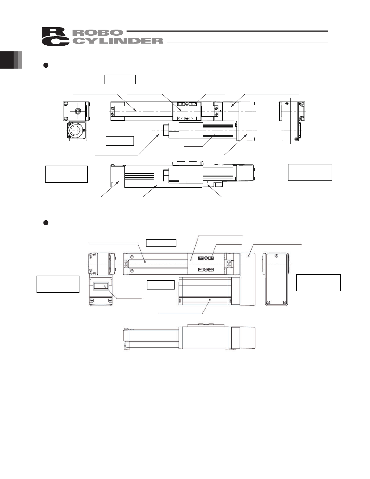
1. Part Names
The names of the actuator parts are indicated below.
In this manual, the right and left are determined by viewing the actuator from the top and from the motor
side.
Also, the front side means the side opposite from the motor.
“Motor coupling types” : RCA2-SA2AC
1. Part Names
Stainless sheet
Opposite Side
of the Motor
Slider cover
Front bracket
* Refer to 2, “External Dimensions” for details.
“Motor coupling types” : RCA2-SA3C/SA4C/SA5C/SA6C
Base
Right Side
Left Side
Side cover
Actuator cable
Motor side
Motor
Motor bracketSlider
Bare housing
Slider cover
Stainless sheet
Right Side
Opposite Side
of the Motor
Left Side
Slider
* Refer to 2, “External Dimensions” for details.
* The connector position shown above assumes that the cable exit direction has not been changed.
Motor unit
Connector
Motor side
11
Page 20
“Motor reversing types” : RCA2-SA2AR
Right Side
1. Part Names
* Refer to 2, “External Dimensions” for details.
Slider coverStainless sheet
Left Side
Actuator cable
Opposite Side
of the Motor
Front bracket
“Motor reversing types” : RCA2-SA3R/SA4R/SA5R/SA6R
Stainless sheet
Base
Right Side
Motor
Pulley cover
Slider
Bare housing
Slider cover
Slider
Reversing bracket
Motor side
Reversing bracket
Opposite Side
of the Motor
Connector
* Refer to 2, “External Dimensions” for details.
12
Left Side
Motor side
Motor unit
Page 21

2. External Dimensions
2.1 RCA2-SA2AC
18.94.4
0.2
0.22
Weight [kg]
468
B
0.23
2. External Dimensions
0.25
10
12
103
0.02)
p
4-M2, Depth 4
3 3
5
7.5
7.5
2H7, Depth 2
F
2-
Secure at least 100
82
ME
L1
22
30st 22.5
L2
SEME ORG
3H7, Depth 2
F
Slot, Depth 2
(25)
15
A×2530
A
L2
L1
ST
123
92
117
174
199
255075
142
224
4
167
249
100
Reamer pitch tolerance
15 (
14.5
22.7
27.2
15.2
20
1
R1.5
16
R1.5
B-M2, Depth 4
Scale 2:1
Detail view of Slot
3H7
13
Page 22

2.2 RCA2-SA3C
]gk[thgieWL
With brake
brake
Without
2. External Dimensions
ABCDM
With brake
2H7, depth 5
2-
4-M3, depth 6
2H7, depth 4 (from bottom face of base)
D-M3, depth 5
Without
ST
brake
50 247.5 292 155. 5 84 0 4 84 0.5 0.7
100 297.5 342 205.5 34 1 6 134 0.6 0.8
150 347.5 392 255.5 84 1 6 184 0.6 0.8
200 397.5 442 305.5 34 2 8 234 0.7 0.9
250 447.5 492 355.5 84 2 8 284 0.7 0.9
300 497.5 542 405.5 34 3 10 334 0.8 1.0
14
Scale 5:1
Detail view of F
(from bottom face of base)
2H7, depth 4
(Side view of the motor when the cable exit direction has been changed (optional)
Brake type
Page 23

2.3 RCA2-SA3C- with Side Cover
]gk[thgieWL
Without
ABCDM
With brake
brake
2. External Dimensions
Without
ST
With brake
brake
50 247.5 292 155 .5 84 0 4 84 0.6 0.8
100 297.5 342 205.5 34 1 6 134 0.6 0.8
150 347.5 392 255.5 84 1 6 184 0.7 0.9
200 397.5 442 305.5 34 2 8 234 0.8 1.0
250 447.5 492 355.5 84 2 8 284 0.8 1.0
300 497.5 542 405.5 34 3 10 334 0.9 1.1
2H7, depth 4 (from bottom face of base)
2H7, depth 5
2-
4-M3, depth 6
D-M3, depth 5
(Side view of the motor when the cable exit direction has been changed (optional)
Scale 5:1
Detail view of F
Brake type
15
Page 24

2.4 RCA2-SA4C
]gk[thgieWL
With brake
brake
Without
2. External Dimensions
ABCDM
With brake
2.5H7, depth 5 (from bottom face of base)
D-M3, depth 5
2.5H7, depth 5
2-
Without
ST
brake
50 274 314.5 165.5 91 0 4 91 0.8 1.1
100 324 364.5 215.5 41 1 6 141 0.9 1.2
150 374 414.5 265.5 91 1 6 191 1 1.3
200 434 464.5 315.5 41 2 8 241 1 1.3
250 474 514.5 365.5 91 2 8 291 1.1 1.4
300 524 564.5 415.5 41 3 10 341 1.2 1.5
350 574 614.5 465.5 91 3 10 391 1.3 1.6
400 624 664.4 515.5 41 4 12 441 1.3 1.6
450 674 714.5 565.5 91 4 12 491 1.4 1.7
500 724 764.5 615.5 41 5 14 541 1.5 1.8
4-M3, depth 6
16
(Side view of the motor when the cable exit direction has been changed (optional)
Scale 5:1
Detail view of F
Brake type
Page 25

2.5 RCA2-SA4C- with Side Cover
]gk[thgieWL
With brake
2. External Dimensions
2.5H7, depth 5 (from bottom face of base)
brake
Without
ABCDM
With brake
brake
Without
D-M3, depth 5
50 274 314.5 165.5 91 0 4 91 0.9 1.2
ST
100 324 364.5 215.5 41 1 6 141 1 1.3
150 374 414.5 265.5 91 1 6 191 1.1 1.4
200 434 464.5 315.5 41 2 8 241 1.1 1.4
250 474 514.5 365.5 91 2 8 291 1.2 1.5
300 524 564.5 415.5 41 3 10 341 1.3 1.6
350 574 614.5 465.5 91 3 10 391 1.4 1.7
400 624 664.4 515.5 41 4 12 441 1.5 1.8
450 674 714.5 565.5 91 4 12 491 1.5 1.8
500 724 764.5 615.5 41 5 14 541 1.6 1.9
2- 2.5H7, depth 5
4-M3, depth 6
Scale 5:1
Detail view of F
(from bottom face of base)
2.5H7, depth 5
(Side view of the motor when the cable exit direction has been changed (optional)
Brake type
Motor cover top: 51
17
Page 26

2.6 RCA2-SA5C
]gk[thgieWL
With brake
brake
Without
2. External Dimensions
ABCDM
2.5H7, depth 5 (from bottom face of base)
D-M4, depth 7
With brake
2- 2.5H7, depth 5
brake
Without
50 272.5 312 175 .5 96 0 4 96 1.1 1.5
ST
100 322.5 362 225.5 46 1 6 146 1.3 1.7
150 372.5 412 275.5 96 1 6 196 1.4 1.8
200 422.5 462 325.5 46 2 8 246 1.5 1.9
250 472.5 512 375.5 96 2 8 296 1.6 2.0
300 522.5 562 425.5 46 3 10 346 1.7 2.1
350 572.5 612 475.5 96 3 10 396 1.8 2.2
400 622.5 662 525.5 46 4 12 446 1.9 2.3
450 672.5 712 575.5 96 4 12 496 2.0 2.4
500 722.5 762 625.5 46 5 14 546 2.1 2.5
550 772.5 812 675.5 96 5 14 596 2.2 2.6
600 822.5 862 725.5 46 6 16 646 2.3 2.7
650 872.5 912 775.5 96 6 16 696 2.4 2.8
700 922.5 962 825.5 46 7 18 746 2.5 2.9
750 972.5 1012 875.5 96 7 18 796 2.6 3.0
800 1022.5 1062 925.5 46 8 20 846 2.7 3.1
4-M4, depth 8
18
Scale 2:1
Detail view of F
(from bottom face of base)
2.5H7, depth 5
Brake type
(Side view of the motor when the cable exit direction has been changed (optional)
Motor cover top: 58
Page 27

2.7 RCA2-SA5C- with Side Cover
2- 2.5H7, depth 5
4-M4, depth 8
2.5H7, depth 5 from bottom face of base
]gk[thgieWL
With brake
2. External Dimensions
brake
Without
ABCDM
D-M4, depth 7
Without
ST
With brake
brake
50 272.5 312 175 .5 96 0 4 96 1.2 1.6
100 322.5 362 225.5 46 1 6 146 1.4 1.8
150 372.5 412 275.5 96 1 6 196 1.5 1.9
200 422.5 462 325.5 46 2 8 246 1.6 2.0
250 472.5 512 375.5 96 2 8 296 1.8 2.2
300 522.5 562 425.5 46 3 10 346 1.9 2.3
350 572.5 612 475.5 96 3 10 396 2.0 2.4
400 622.5 662 525.5 46 4 12 446 2.2 2.6
450 672.5 712 575.5 96 4 12 496 2.3 2.7
500 722.5 762 625.5 46 5 14 546 2.4 2.8
550 772.5 812 675.5 96 5 14 596 2.6 3.0
600 822.5 862 725.5 46 6 16 646 2.7 3.1
650 872.5 912 775.5 96 6 16 696 2.8 3.2
700 922.5 962 825.5 46 7 18 746 3.0 3.4
750 972.5 1012 875.5 96 7 18 796 3.1 3.5
800 1022.5 1062 925.5 46 8 20 846 3.2 3.6
Scale 2:1
Detail view of F
(from bottom face of base)
2.5H7, depth 5
(Side view of the motor when the cable exit direction has been changed (optional)
Brake type
Motor cover top: 58
19
Page 28

2.8 RCA2-SA6C
]gk[thgieWL
With brake
brake
Without
2. External Dimensions
ABCDM
3H7, depth 5 (from bottom face of base)
2-M5, depth 8
2- 3H7, depth 5
Without
ST
With brake
brake
50 292.5 332 180. 5 101 0 4 101 1.5 1.9
100 342.5 382 230.5 51 1 6 151 1.6 2.0
150 392.5 432 280.5 101 1 6 201 1.8 2.2
200 442.5 482 330.5 51 2 8 251 1.9 2.3
250 492.5 532 380.5 101 2 8 301 2.1 2.5
300 542.5 582 430.5 51 3 10 351 2.2 2.6
350 592.5 632 480.5 101 3 10 401 2.3 2.7
400 642.5 682 530.5 51 4 12 451 2.5 2.9
450 692.5 732 580.5 101 4 12 501 2.6 3.0
500 742.5 782 630.5 51 5 14 551 2.8 3.2
550 792.5 832 680.5 101 5 14 601 2.9 3.3
600 842.5 882 730.5 51 6 16 651 3.1 3.5
650 892.5 932 780.5 101 6 16 701 3.2 3.6
700 942.5 982 830.5 51 7 18 751 3.4 3.8
750 992.5 1032 880.5 101 7 18 801 3.5 3.9
800 1042.5 1082 930.5 51 8 20 851 3.7 4.1
4-M5, depth 10
20
Scale 2:1
(Side view of the motor when the cable exit direction has been changed (optional)
Detail view of F
Brake type
Page 29

2.9 RCA2-SA6C- with Side Cover
2- 3H7, depth 5
4-M5, depth 10
3H7, depth 5 (from bottom face of base)
]gk[thgieWL
With brake
brake
Without
ABCDM
2. External Dimensions
D-M5, depth 8
With brake
brake
Without
50 292.5 332 180. 5 101 0 4 101 1.6 2.0
ST
100 342.5 382 230.5 51 1 6 151 1.7 2.1
150 392.5 432 280.5 101 1 6 201 1.9 2.3
200 442.5 482 330.5 51 2 8 251 2.1 2.5
250 492.5 532 380.5 101 2 8 301 2.3 2.7
300 542.5 582 430.5 51 3 10 351 2.4 2.8
350 592.5 632 480.5 101 3 10 401 2.6 3.0
400 642.5 682 530.5 51 4 12 451 2.8 3.2
450 692.5 732 580.5 101 4 12 501 2.9 3.3
500 742.5 782 630.5 51 5 14 551 3.1 3.5
550 792.5 832 680.5 101 5 14 601 3.3 3.7
600 842.5 882 730.5 51 6 16 651 3.5 3.9
650 892.5 932 780.5 101 6 16 701 3.6 4.0
700 942.5 982 830.5 51 7 18 751 3.8 4.2
750 992.5 1032 880.5 101 7 18 801 4.0 4.4
800 1042.5 1082 930.5 51 8 20 851 4.1 4.5
(Side view of the motor when the cable exit direction has been changed (optional)
Scale 2:1
Detail view of F
Brake type
21
Page 30

2.10 RCA2-SA2AR
0.2
0.22
Weight [kg]
468
B
0.23
0.25
10
2. External Dimensions
L1
L2 32.5
12
3
4-M2, Depth 4
103
2H7, Depth 2
F
2-
A
L2
L1
ST
123
92
124.5
255075
117
149.5
142
174.5
4
167
199.5
100
5514.5 st 30
3
89
ME
22
3H7, Depth 2
F
ORGME SE
A×25 15
(25)
0.02)
p
30
Secure at least 100
B-M2, Depth 4
Slot, Depth 2
16
22
Reamer pitch tolerance
15 (
23.9
22.7
27.2
15.2
(1.9)
2.9
20 16.2
41
1
R1.5
R1.5
Scale 2:1
Detail view of Slot
3H7
Page 31

2.11 RCA2-SA3R, Reversing to Left (Right)
With brake
Weight [kg]
brake
Without
2. External Dimensions
(with brake)
Brake type
50 162 143 84 0 4 0.6 0.8
ST L A B C D
100 212 193 34 1 6 0.7 0.9
150 262 243 84 1 6 0.7 0.9
200 312 293 34 2 8 0.8 1.0
250 362 343 84 2 8 0.8 1.0
2H7, depth 4 (from bottom face of base)
4-M3, depth 6
300 412 393 34 3 10 0.9 1.1
(without brake)
D-M3, depth 5
2- 2H7, depth 5
direction has been changed (optional)
(Side view of the motor when the cable exit
Scale 5:1
Detail view of F
23
Page 32

2.12 RCA2-SA3R- with Side Cover, Reversing to Left (Right)
2. External Dimensions
Brake type
With brake
Weight [kg]
brake
Without
(with brake)
2H7, depth 4 from bottom face of base
4-M3, depth 6
50 162 143 84 0 4 0.7 0.9
ST L A B C D
100 212 193 34 1 6 0.7 0.9
150 262 243 84 1 6 0.8 1.0
200 312 293 34 2 8 0.9 1.1
250 362 343 84 2 8 0.9 1.1
300 412 393 34 3 10 1.0 1.2
(without brake)
D-M3, depth 5
2H7, depth 5
2-
Scale 5:1
Detail view of F
24
direction has been changed (optional)
(Side view of the motor when the cable exit
Page 33

2.13 RCA2-SA4R, Reversing to Left (Right)
(with brake)
Brake type
4-M3, depth 6
(without brake)
With brake
Weight [kg]
brake
Without
50 183 156.5 91 0 4 1.0 1.3
ST L A B C D
100 233 206.5 41 1 6 1.1 1.4
150 283 256.5 91 1 6 1.2 1.5
200 333 306.5 41 2 8 1.2 1.5
250 383 356.5 91 2 8 1.3 1.6
300 433 406.5 41 3 10 1.4 1.7
350 483 456.5 91 3 10 1.5 1.8
400 533 506.5 41 4 12 1.5 1.8
450 583 556.5 91 4 12 1.6 1.9
500 633 606.5 41 5 14 1.7 2.0
2. External Dimensions
D-M3, depth 5
2- 2.5H7, depth 5
2.5H7, depth 5 (from bottom face of base)
Scale 5:1
Detail view of F
direction has been changed (optional)
(Side view of the motor when the cable exit
25
Page 34

2.14 RCA2-SA4R- with Side Cover, Reversing to Left (Right)
2. External Dimensions
With brake
Weight [kg]
brake
Without
(with brake)
Brake type
4-M3, depth 6
50 183 156.5 91 0 4 1.1 1.4
ST L A B C D
100 233 206.5 41 1 6 1.2 1.5
150 283 256.5 91 1 6 1.3 1.6
200 333 306.5 41 2 8 1.3 1.6
250 383 356.5 91 2 8 1.4 1.7
300 433 406.5 41 3 10 1.5 1.8
350 483 456.5 91 3 10 1.6 1.9
400 533 506.5 41 4 12 1.7 2.0
450 583 556.5 91 4 12 1.8 2.1
500 633 606.5 41 5 14 1.9 2.2
(without brake)
D-M3, depth 5
2- 2.5H7, depth 5
2.5H7, depth 5 (from bottom face of base)
Scale 5:1
Detail view of F
26
direction has been changed (optional)
(Side view of the motor when the cable exit
Page 35

2.15 RCA2-SA5R, Reversing to Left (Right)
(with brake)
Brake type
4-M4, depth 8
(without brake)
With brake
Weight [kg]
brake
Without
50 189.5 163 96 0 4 1.4 1.8
ST L A B C D
100 239.5 213 46 1 6 1.6 2.0
150 289.5 263 96 1 6 1.7 2.1
200 339.5 313 46 2 8 1.8 2.2
250 389.5 363 96 2 8 1.9 2.3
300 439.5 413 46 3 10 2.0 2.4
350 489.5 463 96 3 10 2.1 2.5
400 539.5 513 46 4 12 2.2 2.6
450 589.5 563 96 4 12 2.3 2.7
500 639.5 613 46 5 14 2.4 2.8
550 689.5 663 96 5 14 2.5 2.9
600 739.5 713 46 6 16 2.6 3.0
650 789.5 763 96 6 16 2.7 3.1
700 839.5 813 46 7 18 2.8 3.2
750 889.5 863 96 7 18 2.9 3.3
800 939.5 913 46 8 20 3.0 3.4
2. External Dimensions
D-M4, depth 7
2- 2.5H7, depth 5
2.5H7, depth 5 (from bottom face of base)
Scale 2:1
Detail view of F
changed (optional)
(Side view of the motor when the cable exit direction has been
27
Page 36

2.16 RCA2-SA5R- with Side Cover, Reversing to Left (Right)
Weight [kg]
(with brake)
With brake
Without
brake
2. External Dimensions
Brake type
50 189.5 163 96 0 4 1.5 1.9
ST L A B C D
100 239.5 213 46 1 6 1.7 2.1
150 289.5 263 96 1 6 1.8 2.2
200 339.5 313 46 2 8 1.9 2.3
250 389.5 363 96 2 8 2.1 2.5
300 439.5 413 46 3 10 2.2 2.6
350 489.5 463 96 3 10 2.3 2.7
400 539.5 513 46 4 12 2.5 2.9
450 589.5 563 96 4 12 2.6 3.0
500 639.5 613 46 5 14 2.7 3.1
550 689.5 663 96 5 14 2.9 3.3
600 739.5 713 46 6 16 3.0 3.4
650 789.5 763 96 6 16 3.1 3.5
700 839.5 813 46 7 18 3.3 3.7
750 889.5 863 96 7 18 3.4 3.8
800 939.5 913 46 8 20 3.5 3.9
4-M4, depth 8
(without brake)
D-M4, depth 7
2- 2.5H7, depth 5
2.5H7, depth 5 (from bottom face of base)
28
been changed (optional)
(Side view of the motor when the cable exit direction has
Scale 2:1
Detail view of F
Page 37

2.17 RCA2-SA6R, Reversing to Left (Right)
(with brake)
Brake type
4-M5, depth 10
(without brake)
With brake
Weight [kg]
brake
Without
50 194.5 168 101 0 4 1.8 2.2
ST L A B C D
100 244.5 218 51 1 6 1.9 2.3
150 294.5 268 101 1 6 2.1 2.5
200 344.5 318 51 2 8 2.2 2.6
250 394.5 368 101 2 8 2.4 2.8
300 444.5 418 51 3 10 2.5 2.9
350 494.5 468 101 3 10 2.6 3.0
400 544.5 518 51 4 12 2.8 3.2
450 591.5 568 101 4 12 2.9 3.3
500 644.5 618 51 5 14 3.1 3.5
550 694.5 668 101 5 14 3.2 3.6
600 744.5 718 51 6 16 3.4 3.8
650 794.5 768 101 6 16 3.5 3.9
700 844.5 818 51 7 18 3.7 4.1
750 894.5 868 101 7 18 3.8 4.2
800 944.5 918 51 8 20 3.9 4.3
2. External Dimensions
2- 3H7, depth 5
D-M5, depth 8
3H7, depth 5 (from bottom face of base)
Scale 2:1
Detail view of F
been changed (optional)
(Side view of the motor when the cable exit direction has
29
Page 38

2.18 RCA2-SA6R- with Side Cover, Reversing to Left (Right
2. External Dimensions
With brake
Weight [kg]
brake
Without
(with brake)
Brake type
50 194.5 168 101 0 4 1.9 2.3
ST L A B C D
100 244.5 218 51 1 6 2.0 2.4
150 294.5 268 101 1 6 2.2 2.6
200 344.5 318 51 2 8 2.4 2.8
250 394.5 368 101 2 8 2.6 3.0
300 444.5 418 51 3 10 2.7 3.1
350 494.5 468 101 3 10 2.9 3.3
400 544.5 518 51 4 12 3.1 3.5
450 591.5 568 101 4 12 3.2 3.6
500 644.5 618 51 5 14 3.4 3.8
550 694.5 668 101 5 14 3.6 4.0
600 744.5 718 51 6 16 3.8 4.2
650 794.5 768 101 6 16 3.9 4.3
700 844.5 818 51 7 18 4.1 4.5
750 894.5 868 101 7 18 4.3 4.7
800 944.5 918 51 8 20 4.5 4.9
4-M5, depth 10
(without brake)
2- 3H7, depth 5
D-M5, depth 8
D-M5, depth 8
3H7, depth 5 (from bottom face of base)
Scale 2:1
Detail view of F
been changed (optional)
(Side view of the motor when the cable exit direction has
30
Page 39

3. Cable Drawings
(
p
(
)
3.1 AMEC, ASEP Controller Cables
Integrated motor/encoder cable
(CB-APSEP-MPA***)
*** indicates the cable length (L). Up to 20m can be specified.
Example) 080 = 8 m
3. Cable Drawings
[1][2]
[5]
[6]
Model Nameplate
Lot number
[3][4]
No. Item Model number Manufacturer
1 Housing
2 Contact
3 Housing PADP-24V-1-S (white, 2.0-mm pitch, 24 poles)
4 Contact
5 Coupler cover TMS-4ZB008
6 ZUL2854-OHFRPCVVSW
D-1100D 1-1827863-1 (black, 2.0-mm pitch, 22
poles)
D-1 1827570-2 (AWG 22 to 18, 1.08 to 1.6 )
SPND-001T-C0.5 (AWG 26 to 22, 1.0 to 1.5 )
25AWG x 6P + 25AWG x 2C + 22AWG x 6C,
TS08V0350
Terminal number
on actuator side
[1] [3]
Wiring diagram
Black
White
Brown
Green
Yellow
Red
Orange
Gray
White
Yellow
Red
Green
Black
Brown
Black
identification ta
Brown
identification tape
Green
(identification tape)
Red
(identification tape)
White
(identification tape)
Yellow
(identification tape)
Terminal number
on controller side
AMP
JST
TATSUTA ELECTRIC
WIRE & CABLE
TATSUTA ELECTRIC
WIRE & CABLE
Shield
31
Page 40

)
(
)
)
3.2 ACON, ASEL Controller Cables
RCA2 Integrated motor/encoder cable
(CB-ACS-MPA***)
[1][2]
*** indicates the cable length (L). Up to 20m can be specified.
Example) 080 = 8 m
3. Cable Drawings
No. Item Model number Manufacturer
[1] Receptacle housing D-1100D 1-1827863-1 AMP
[2] Receptacle contact D-1 1827570-2 AMP
[3] Socket DF1E-3S-2.5C Hirose
[4] Socket contact DF1E-2022SCF Hirose
[5] Housing PHDR-18VR JST
[6] Contact SPHD-001T-P0.5 JST
[7] UL2854-VVSWKA TS06V1200 (25AWG x 7P + 22AWG x 6C)
Terminal number
on actuator side
[7]
Model Nameplate
Wiring diagram
Red
Yellow
Black
[3][4]
[7]
[5][6]
TATSUTA ELECTRIC
WIRE & CABLE
Terminal number
on controller side
[3]
Yellow (Redx)
Yellow (Bluex)
[1]
Pink (Redx)
Pink (Bluex)
White (Redx)
White (Bluex
Orange (Redx)
Orange (Bluex)
Gray (Redx)
Gray(Bluex
Orange (Red/continuous)
Orange (Blue/continuous)
Gray (Red/continuous)
Gray (Blue/continuous)
Shield
[5]
32
Page 41

4. Options
4.1 Brake Type
The brake is a mechanism designed to prevent the slider from dropping on a vertically installed actuator
when the power or servo is turned off.
Use the brake to prevent the installed load, etc., from being damaged due to the falling slider.
The applicable model number for this option is “B.”
4.2 Power-saving Measure
As shown in the table below, the maximum load current of the standard specification and high
acceleration/deceleration specification can be lowered.
The applicable model number for this option is “LA.”
For details, refer to the section on power capacity in the manual for your ACON/ASEL controller.
Standard specification /
Model
SA3, SA5 4.4 A 2.5 A
SA6 4.0 A 2.2 A
SA4 5.1 A 3.4 A
High acceleration/deceleration specification
Maximum load current
Energy-saving measure
Maximum load current
4.3 No-cover Specification
Actuators of the no-cover specification have no side covers.
The applicable model number for this option is “NCO.”
(For the external dimensions of actuators with/without side covers, refer to 2, “External Dimensions.”)
4.4 Reversed-home Specification
The standard home position is on the motor side. However, the motor position will be reversed if it is
desirable in view of the layout of the system, etc.
(Note) The home position is adjusted at the factory before shipment. If you wish to change the home after
the delivery of your actuator, you must return the actuator to IAI for adjustment.
4. Options
33
Page 42

4.5 Changing the Cable Exit Direction
If the cable exit direction is changed, the applicable part of the model number must also be changed.
A desired direction can be selected from among the five options of top (CJT in the model number), right
(CJR), left (CJL), bottom (CJB) and outer (CJO).
4. Options
Left: CJL
Top: CJT
Right: CJR
Top: CJT
Top: CJT
Outer: CJO
Outer: CJO
BJC:mottoBBJC:mottoB
Straight type
Bottom: CJB
Motor-reversing type,
reversed to left (ML)
Motor-reversing type,
reversed to left (MR)
4.6 Motor Reversing to Left, Motor Reversing to Right
This option can be spesified for the motor reversing types SA2AR, SA2BR, SA3R, SA4R, SA5R and SA6R,
“ML” indicates reversing to the left, while “MR” indicates reversing to the right, as viewed from the motor side.
ML
(Left)
MR
(Right)
34
Page 43

5. Checking after Unpacking
After unpacking, check the product condition and the included items.
5.1 Included Items
metI.oN Model number
1 Actuator
Accessories
2 RCA integrated motor/encoder cable
3 First Step Guide
4 Operating Manual (CD/DVD)
5 Safety Guide
5.2 Operation Manuals Relating to This Product
1 Operation Manual for 5610JMrellortnoCLESA
2 Operation Manual for ACON-C/CG/CF Controller MJ0176
3 Operation Manual for ACON-CY Controller MJ0167
4 Operation Manual for ACON-SE Controller MJ0171
5 Operation Manual for ACON-PL/PO Controller MJ0166
6 Operation Manual for MEC Controller MJ0245
7 Operation Manual for PSSEP/ 6120JMrellortnoCPESA
8 Operation Manual for PC Software IA-101-X-X-MW/IA-101-X-USBMW MJ0154
9 Operation Manual for PC Software RCM-101MW/RCM-101-USB MJ0155
10 Operation Manual for MEC PC Software MJ0248
11 Operation Manual for Teaching Pendant SEL-T/TD MJ0183
12 Operation Manual for Teaching Pendant CON-T/TG MJ0178
13 Operation Manual for Touch Panel Teaching Pendant CON-PT/PD/PG MJ0227
14 Operation Manual for Dedicated ASEP/PSEP Touch Panel Teaching SEP-PT MJ0217
15 Operation Manual for Simple Teaching Pendant RCM-E MJ0174
16 Operation Manual for Data Setter RCM-P MJ0175
17 Operation Manual for Touch Panel Display RCM-PM-01 MJ0182
Refer to “How to Read the Model Nameplate”
and “How to Read the Model Number.”
CB-APSEP-MPA : AMEC, ASEP type
CB-ACS-MPA
: ACON, ASEL type
5. Checking after Unpacking
lortnoCemaN.oN No.
35
Page 44

r
p
5.3 How to Read Model Nameplate
Model
Serial numbe
5.4 How to Read Model Number
<Series name>
<Type>
SA2AC
SA3C
SA4C
SA5C
SA6C
Motor reversing
SA2AR
SA2AC
SA4R
5. Checking after Unpacking
SA5R
SA6R
<Encoder type>
I: Incremental
<Motor type>
5 (5 W) : SA2AC, SA2AR
10 (10 W): SA3C, SA3R
20 (20 W): SA4C, SA4R
SA5C, SA5R
30 (30 W): SA6C, SA6R
<Option>
B: With brake
CJT: Different cable exit direction (top)
CJR: Different cable exit direction (right)
CJL: Different cable exit direction (left)
CJB: Different cable exit direction (bottom)
CJO: Different cable exit direction (outer)
ML: Motor left reversing type
MR: Motor right reversing type
LA: Power-saving measure
NCO: No-cover specification
NM: Reversed-home s
<Cable length>
N: None
P: 1 m
S: 3 m
M: 5 m
X
: Specified length
<Applicable controller>
A1: ASEL
ACON-C/CG
ACON-C/CG
ACON-CY
ACON-SE
ACON-PL/PO
A3: AMEC
ASEP
ecification
<Stroke>
<Lead>
SA2AC, SA2AR
1/2/4
SA3C, SA3R
2/4/6
SA4C, SA4R
2.5/5/10
SA5C, SA5R
3/6/12
SA6C, SA6R
3/6/12
SA5C
20
SA6C, SA6R
3/6/12
SA6C
20
36
Page 45

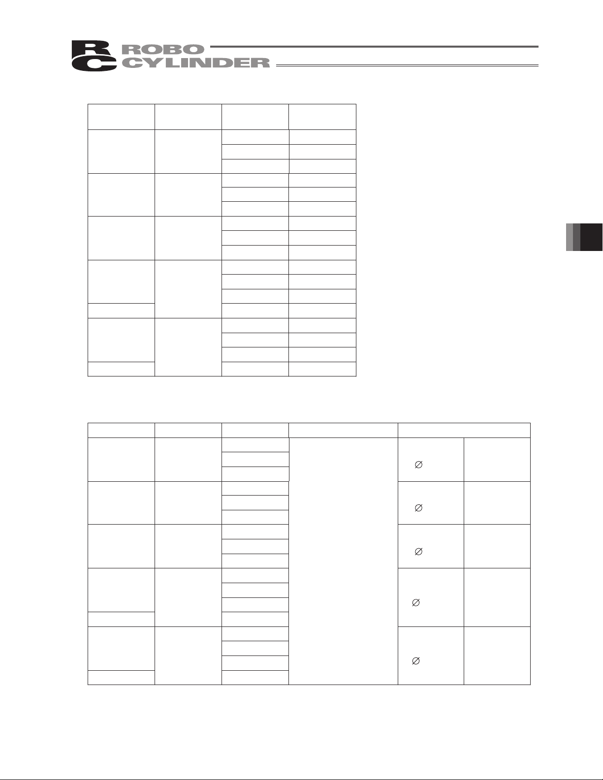
6. Specifications
(1) Maximum speed
The maximum speed of this ROBO Cylinder is limited to prevent resonance of the ball screw shaft and
also due to limitation of the motor speed. Observe the maximum speed limits specified in the table.
Strokes and Maximum Speed Limits (Unit: mm/s)
Mode
SA2A
SA3
SA4
SA5
SA5C
SA6
SA6C
Motor
Type
5W
10W
20W
20W
20W
30W
30W
Lead
(mm)
25 50 75 100 150 200 250 300 350 400 450 500 550 600 650 700 750 800
100
200
300
125
250
380
150
300
380
380
380
150
300
380
380
380
50
100
200
540
540
540
540
540
660
660
660
660
100
200
300
770
770
770
770
860
860
2.5
1
2
4
180
2
4
6
5
10
3
6
12
20
3
6
12
20
Stroke (mm)
125
250
500
150
300
600540
940
800 (stroke 250 to 650, installed vertically)
150
300
600
940
800 (stroke 250 to 650, installed vertically)
1000
1000
140
285
570
140
285
570
120
245
490
910
120
245
490
910
105
210
425
790
790
105
210
425
790
790
185
370
690
690
185
370
690
690
80
90
165
330
610
610
80
90
165
330
610
610
(Note) The maximum speed may not be reached depending on the acceleration/deceleration setting.
Caution: Do not set a speed or acceleration/deceleration exceeding the applicable rating. Doing so
may result in vibration, failure or shorter life.
If an acceleration/deceleration exceeding the rating is set, creep may occur or the
coupling may slip.
6. Specifications
37
Page 46

(2) Acceleration and payloads
6. Specifications
Model Motor type
SA2A 10 W
SA3 10 W
SA4 20 W
SA5 20 W
SA5C 20 W
Lead
(mm)
1
2
4
2
4
6
2.5
5
10
3
6
12
Rated acceleration
(G)
Horizontal
Vertical
Horizontal
Vertical
Horizontal
Vertical
Horizontal
Vertical
Horizontal
Vertical
Horizontal
Vertical
Horizontal
Vertical
Horizontal
Vertical
Horizontal
Vertical
Horizontal
Vertical
Horizontal
Vertical
Horizontal
Vertical
Horizontal
Vertical
3.0
0.3
3.0
0.3
3.0
0.3
0.2
0.2
0.2
0.2
0.2
0.2
0.2
0.2
0.2
0.2
Maximum speed
(mm/s)
50
100
200
100
200
300
125
250
500
150
300
600
1000 2
800 (stroke 250 to 650,
installed vertically)
Payload
2
1
1
0.5
0.5
0.25
32.0
1.5
23.0
1
13.0
0.5
63.0
3
43.0
1.5
23.0
1
93.0
3
63.0
1.5
33.0
1
0.5
38
3
SA6 30 W
6
12
SA6C 30 W 20
Horizontal
Vertical
Horizontal
Vertical
Horizontal
Vertical
Horizontal
Vertical
0.2
0.2
0.2
0.3 1000 2
0.2
800 (stroke 250 to 650,
Note) Maximum speed may not be reached on all strokes.
The maximum speed of each model with a longer stroke will be less than the
applicable maximum speed shown in the table.
[Refer to (1), “Maximum speed.” ]
150
300
600
installed vertically)
013.0
4
73.0
2
43.0
1.5
0.5
Page 47
(3) Rated thrust
Model Motor type
SA2A 5 W
SA3 10 W
SA4 20 W
SA5
20 W
SA5C
SA6
30 W
SA6C
Lead
(mm)
Rated thrust
(N)
1 85.5
2 42.3
4 21.4
285
443
628
2.5 136
568
10 34
368
634
12 17
20 10.1
3 105
653
12 26
20 16
6. Specifications
(4) Drive method
Model Motor type Lead Encoder pulses
SA2A 5 W
SA3 10 W
SA4 20 W
SA5
20 W
SA5C
SA6
30 W
SA6C
*1 Number of pulses input to the controller.
1
2
4
2
4
6
2.5
5
10
3
6
12
20
3
6
12
20
800
*1
Drive method
Ball screw
4mm
Ball screw
6mm
Ball screw
8mm
Ball screw
10 mm
Ball screw
10 mm
Rolled, C10
Rolled, C10
Rolled, C10
Rolled, C10
Rolled, C10
39
Page 48

(5) Common specifications
*1 Default value
6. Specifications
Specification
Item
Positioning repeatability
Backlash
*1
*1
SA5C, SA6C – Lead
other than 20 mm
SA5C, SA6C – Lead 20 mm
r0.02 mm r0.03 mm
0.1 mm or less
Base Material: Aluminum with special alumite treatment
40
Page 49

7. Notes on Use Regarding Maximum Speed and Loading Mass
[1] Maximum speed, loading mass
Determine which models you can choose from by the maximum speed and payload capacity.
x AC servo motor (Graph 1)
How to decide: If your maximum speed and payload capacity are within the usage range in the
graph, you can use the model.
7. Notes on Use Regarding Maximum Speed and Loading Mass
41
Page 50

Graph 1 Servo Motor: RCA2
ࠉ
Horizontal
Correlation of speed and payload (Horizontal)
Lead 2
Vertical
Correlation of speed and payload (Vertical)
Lead 4
SA3
Lead 6
Payload (kg) Payload (kg) Payload (kg) Payload (kg)
Correlation of speed and payload (Horizontal)
Lead 2.5
Lead 5
SA4
Correlation of speed and payload (Horizontal)
10
8
6
SA5
4
2
0
0
100 200 300 400 500 600 700 800 900 1000
(Note) The line of “Lead 20” applies to the SA5C only.
Correlation of speed and payload (Horizontal)
7. Notes on Use Regarding Maximum Speed and Loading Mass
SA6
12
10
8
6
4
2
0
0
100 200 300 400 500 600 700 800 900 1000
(Note) The line of “Lead 20” applies to the SA6C only.
Lead 3
Lead 6
Lead 3
Lead 6
Speed (mm/sec)
Lead 10
Lead 12
Lead 20
Lead 12
Lead 20
Lead 2
Lead 4
Payload (kg) Payload (kg) Payload (kg) Payload (kg)
Speed (mm/sec) Speed (mm/sec)
Lead 6
Correlation of speed and payload (Vertical)
Lead 2.5
Lead 5
Speed (mm/sec) Speed (mm/sec)
Lead 10
Correlation of speed and payload (Vertical)
5
4
3
2
1
0
0
100 200 300 400 500 600 700 800 900 1000
(Note) The line of “Lead 20” applies to the SA5C only.
The maximum speed at a lead of 20 and stroke of
250 to 600 is 800 mm/sec.
Lead 3
Lead 6
Lead 12
Lead 20
Speed (mm/sec) Speed (mm/sec)
Correlation of speed and payload (Vertical)
5
4
3
2
1
0
0
(Note) The line of “Lead 20” applies to the SA5C only.
Lead 3
Lead 6
Lead 12
Lead 20
100 200 300 400 500 600 700 800 900 1000
The maximum speed at a lead of 20 and stroke of
250 to 600 is 800 mm/sec.
Speed (mm/sec)
42
Page 51

8. Installation and Storage/Preservation
8.1 Installation Environment
Do not use this product in the following environment
It is generally the environment where a worker can work without any protection gear.
Also make sure to keep enough work space necessary for maintenance.
• Location exposed to radiant heat from a huge heat source such as the heat treatment
• Location where the surrounding air temperature exceeds the range of 0 to 40oC
• Location where condensation occurs due to abrupt temperature changes
• Location where relative humidity exceeds 85%RH
• Location exposed to direct sunlight
• Location exposed to corrosive gases or combustible gases
• Location exposed to significant amount of dust, salt or iron powder (Outside of ordinary assembly plant)
• Location where water, oil (includes oil mist and cutting fluid) or chemical is splashed
• Location where the product main body receives vibration or hit impact
When using the product in any of the locations specified below, provide a sufficient shield.
• Location subject to electrostatic noise
• Location where exposed to the influence of strong electric or magnetic field
• Location where exposed to the influence of ultraviolet or radiant rays
Open space required for maintenance inspection
8. Installation and Storage/Preservation
250mm
250mm
300mm
8.2 Storage/preservation Environment
The storage and preservation environment should comply with the same standards as those for the
installation environment. In particular, when the machine is to be stored for a long time, pay close
attention to environmental conditions so that no dew condensation forms.
Unless specially specified, moisture absorbency protection is not included in the package when the
machine is delivered. In the case that the machine is to be stored and preserved in an environment
where dew condensation is anticipated, take the condensation preventive measures from outside
of the entire package, or directly after opening the package.
For storage and preservation temperature, the machine withstands temperatures up to 60oC for a
short time, but in the case of the storage and preservation period of 1 month or more, control the
temperature to 50oC or less.
Storage and preservation should be performed in the horizontal condition. In the case it is stored in the
packaged condition, follow the posture instruction if any displayed on the package.
43
Page 52

9. Installation
This chapter explains how to install the actuator on your mechanical system.
9.1 General Rules on Installation
Follow the information below when installing the actuator, as a rule.
Do pay attention to these items (except when custom-order models).
: Possible : Daily inspection is required x: Not possible
Model
SA3
SA4
SA5
SA6
Installation posture
Horizontal installation
Vertical installation Sideway installation
Vertical Sideways Ceiling mountHorizontal
Ceiling mount installation
9. Installation
Caution: 1. When the unit is installed vertically oriented, attempt to put the motor up unless there
is a special reason. Putting the motor on the lower side would not cause a problem
in an ordinary operation. However, it may rarely cause a problem, when it is not
operated for a long period, depending on the surrounding environment (especially
high temperature), caused by the grease being separated and the base oil flowing
into the motor unit.
2. Can be installed sideways or ceiling mount, but the actuators must be checked
daily. If the actuator is installed sideways or ceiling mount, the stainless sheet may
sbe slacked or displaced. If the actuator is used continuously while the stainless
sheet is slacked or displaced, the stainless sheet may break or other problems may
occur. Check the actuator daily and if the stainless sheet is found slacked or
displaced, make installation adjustment of the stainless sheet. [Refer to 13.9
Replacement (for models with slider cover).]
44
Page 53

9.2 Installation of Actuator
9.2.1 Installation of RCA2-SA2AC and SA2AR
This actuator has the screw holes for mounting so it can be fixed from the rear side.
Also, there are a reamed hole and a slotted hole for positioning pins.
3H7, Depth 2
Slot, Depth 2
16
F
B-M2, Depth 4
1
R1.5
3H7
Detail view of Slot
R1.5
(25)
A×2530
15
ST
25
50
75
100
Scale 2:1
Screw diameter
and max. screw
mating depth
M2, depth 4 M2 0.42 N-m (0.043 kgf-m) 0.25 N-m (0.026 kgf-m)
Mounting
Mounting
bolt
screw
Bolt bearing surface is
steel
Tightening torque
Bolt bearing surface is
aluminum
L2
L1
174
199
224
249
92
117
142
167
Reamed hole (mm)
3H7, depth 2
from bottom face of base
9. Installation
B
A
4
1
6
2
8
3
10
4
Slot
Refer to
the diagram
45
Page 54

9.2.2 Installation of RCA2-SA3C, SA4C, SA5C, SA6C, SA3R, SA4R, SA5R and SA6R
The surface to mount the main unit should be a machined surface or a plane that possesses an equivalent
accuracy and the flatness should be within 0.05mm. Also, the platform should have a structure stiff enough
to install the unit so it would not generate vibration or other abnormality.
This actuator has the screw holes for mounting so it can be fixed from the rear side.
(Note that tap hole size depends on model. Please see diagrams below and 2, "External Dimensions.")
The actuator also contains reamed holes for use with positioning pins.
9. Installation
Slider type
Screw diameter
Model
and max. screw
mating depth
SA3 M3, depth 5 M3 1.54 N-m (0.16 kgf-m) 0.83 N-m (0.085 kgf-m) 17
SA4 M3, depth 5 M3 1.54 N-m (0.16 kgf-m) 0.83 N-m (0.085 kgf-m) 21
SA5 M4, depth 7 M4 3.59 N-m (0.37 kgf-m) 1.76 N-m (0.18 kgf-m) 26
SA6 M5, depth 8 M5 7.27 N-m (0.74 kgf-m) 3.42 N-m (0.35 kgf-m) 31
Mounting
Mounting
bolt
screw
Bolt bearing surface is
steel
Tightening torque
Bolt bearing surface is
A (mm) Reamed hole (mm)
aluminum
2H7, depth 4
from bottom face of base
2.5H7, depth 5
from bottom face of base
2.5H7, depth 5
from bottom face of base
3H7, depth 5
from bottom face of base
46
Page 55

Tightening screws
Use hexagonal socket head bolts for the male threads for installing the base.
Use of high-tension bolts meeting at least ISO 10.9 is recommended.
The length of thread engagement should be 1.8 times more than the nominal diameter, and pay
attention not to stick the screw out inside the actuator.
Caution: Be careful when selecting the bolt length. If bolts of inappropriate lengths are used, the
tapped holes may be damaged, actuator mounting strength may become insufficient, or
contact with driving parts may occur, resulting in lower precision or unexpected accidents.
9. Installation
47
Page 56

9.3 Mounting Surface
The platform to install the actuator should possess a structure that ensures enough stiffness,
and should be free from vibration.
RCA2-SA3C, SA4C, SA5C, SA6C, SA3R, SA4R, SA5R, SA6R
The side and bottom faces of the base provide reference surfaces for slider travel. When it is
necessary that the slider moves in a highly precise fashion, ensure that the device is installed at
the direction that is based on the position of these surfaces.
9. Installation
Follow the diagram below when installing the device using the reference surface.
Reference
surface
Slider type
Caution: Because the side and bottom faces of the base provide reference surfaces for slider travel
as shown in the above diagram, conduct installation based on the position of this side
when precision is required.
R0.3 or less
Reference
surface
Model Length of A (mm)
Slider type 2 to 4 or less
48
Page 57

9.4 Installation of the Load
A
Please attach the load to the device using the tap holes in the slider.
The process for attaching these to the main unit is similar to the installation process of the main
unit. Use of high-tension bolts meeting at least ISO-10.9 standard is recommended for mounting.
The table below shows the recommended tightening torque.
There are two reamed holes on the slider, so if you need to be able to secure and detach the load
multiple times, please use these holes. Also, if you require precision in your attachment, such as a
right angle, use one of the reamed holes to make fine adjustments.
* When using reamed holes, we recommend using an H7 pin. Also, do not force the pin into
the hole. Instead, press it gently in until it fits.
For exact thread depth and reamed hole depth, please see the table below.
Do not tighten the mounting screws to a torque beyond the applicable torque specified in the table
below. Doing so may damage the tapped holes.
RCA2-SA2AC/SA2AR
Reamer pitch tolerance p0.02)
15 (
103
12
2-F2H7, Depth 2
7.557.5
3 3
4-M2, Depth 4
RCA2-SA3C/SA4C/SA5C/SA6C/SA3R/SA4R/SA5R/SA6R
Model A B C D E
9. Installation
reamed pitch: 0.02)
Mounting bolt
Nominal thread size Tightening torque
SA3 17 11 17
SA4 20 14 21
SA5 26 14 22
SA6 31 15 25
2H7,
depth 5
2.5H7,
depth 5
2.5H7,
depth 5
3H7,
depth5
M3 D6 M3
M3 D6 M3
M4 D8 M4
M5 D10 M5
0.83 N-m
(0.085 kgf-m)
0.83 N-m
(0.085 kgf-m)
1.76 N-m
(0.18 kgf-m)
3.42 N-m
(0.35 kgf-m)
49
Page 58

10. Connecting with Controller
Both for the controller itself and for the connection cable between the controller and actuator (RCA2), use
a dedicated IAI controller and dedicated connection cable.
This section explains the wiring method for a single axis.
If the dedicated connection cable cannot be secured, reduce the load on the cable by allowing it to
deflect only by the weight of the cable or wire it in a self-standing cable hose, etc., having a large
radius.
Do not cut and reconnect the dedicated connection cable for extension or shorten the cable.
Do not pull on the dedicated connection cable or bend it forcibly.
Please consult with IAI if you require a different kind of cable than the one supplied.
Dedicated controller
10. Connecting with Controller
RCA2-XX
AMEC
ASEP
Dedicated connection cable
(connects controller and RCA2)
r=68 mm min. (unfastened)
r=34 mm min. (fastened)
Dedicated connection cable
Servo motor cable: CB-APSEP-MPA***
*) *** indicates the cable length. Up to 20m can be specified.
Example) 080 = 8 m
50
(Note) RCA2-SA2AC and SA2AR cannot be run with AMEC controller.
Page 59

Dedicated controller
ASEL
ACON
Dedicated connection cable
Servo motor cable: CB-ACS-MPA***
*) *** indicates the cable length. Up to 20m can be specified.
Example) 080 = 8 m
Dedicated connection cable
(connects controller and RCA2)
r=84 mm min. (unfastened)
r=42 mm min. (fastened)
10. Connecting with Controller
(Note) RCA2-SA2AC and SA2AR cannot be run with ASEL or ACON controller.
51
Page 60

When building an application system using the actuator and controller, incorrect wiring or connection of
each cable may cause broken wire, poor contact or other unexpected problem. The prohibited items
relating to cable wiring are explained below.
● Do not cut and reconnect the cable to extend or shorten the cable.
● If the cable cannot be secured, reduce the load on the cable by allowing it to deflect only by the weight
of the cable or wire it in a self-standing cable hose, etc., having a large radius.
● Prevent the cable from bending at the same point.
Steel band
(piano wire)
Bundle loosely.
● Do not let the cable bend, kink or twist.
● Do not pull the cable with a strong force.
● Do not let the cable receive a turning force at a single point.
10. Connecting with Controller
● Do not pinch, drop a heavy object onto or cut the cable.
52
Page 61

x When fixing the cable, provide a moderate slack and do not tension it too tight.
Do not use a spiral
tube where the cable
flexes frequently.
x Separate the IO and communication lines from the power and drive lines. Do not wire them together in
the same duct.
Power line
Duct
I/O lines
(flat cable)
x Pay attention to the following points when using a cable track.
x Do not let the cable get tangled or kinked in a cable track or flexible tube. When bundling the cable,
keep a certain degree of flexibility (so that the cable will not become too taut when bent).
x Do not cause the cables to occupy more than 60% of the space in the cable track.
Cable track
Cable
Warning
z Always turn off the controller power before connecting/disconnecting cables. If cables are
connected/disconnected while the power is still supplied, the actuator may malfunction and a serious
injury or equipment damage may occur.
z Loose connectors may cause the actuator to malfunction and create a dangerous situation. Be sure
to confirm that all connectors are securely connected.
10. Connecting with Controller
53
Page 62

11. Notes on Operation
11.1 Placing a Load on the Actuator
11.1.1 Allowable moment
Do not exceed the load ratings given in the specification table below.
In particular, be careful not to exceed the load moment, overhang load length, and maximum payload
capacity for the slider.
(See diagram below.)
Allowable dynamic load moment Unit: N·m (kgf·m)
cMbMaM
SA2A 0.18 (0.018) 0.16 (0.016) 0.23 (0.023)
SA3
SA4 3.04 (0.31) 4.31 (0.44) 5.00 (0.51)
SA5 3.92 (0.40) 5.58 (0.57) 8.53 (0.87)
SA6 4.31 (0.44) 6.17 (0.63) 10.98 (1.12)
Allowable static load moment Unit: N·m (kgf·m)
SA2A 2.3 (0.23) 1.9 (0.19) 2.9 (0.30)
SA3 5.0 (0.51) 7.1 (0.72) 7.9 (0.81)
SA4 6.8 (0.69) 9.7 (0.99) 13.3 (1.36)
SA5 10.2 (1.04) 14.6 (1.49) 22.4 (2.29)
1.96 (0.2) 2.84 (0.29) 3.14 (0.32)
cMbMaM
Make sure that the load on the table front plate does not exceed the moment Ma if operating a
slider type. When calculating the load moment, see 11.1.1, "Positioning the guide to calculate
the load moment" below.
11. Notes on Operation
Load moment direction
"Slider type"
SA6 17.6 (1.80) 25.2 (2.57) 44.5 (4.54)
54
Page 63

Allowable overhang lengths
Model Ma direction Mb direction Mc direction
SA2A 40 mm or less 40 mm or less 40 mm or less
SA3
100 mm or less 100 mm or less 100 mm or less
SA4 120 mm or less 120 mm or less 120 mm or less
SA5 130 mm or less 130 mm or less 130 mm or less
SA6 150 mm or less 150 mm or less 150 mm or less
Overhangload length direction
Mb, Mc direction Ma direction
11. Notes on Operation
55
Page 64

(Note) When calculating the moment in Ma or Mc direction, offset the reference position by l mm from
the top surface of the slider, as shown in the figure below.
“Slider type”
Ma, Mc moment
guide offset distance
Caution: Make sure the load installed on the actuator does not exceed the allowable overhang load length
11. Notes on Operation
Model SA2A SA3 SA4 SA5 SA6
A (mm) 23.5 29.5 36.5 43.5 47
(L). If the load exceeds the allowable overhang load length, vibration may occur or the settling
time may become longer.
Also note that if the allowable load moment is exceeded, not only the life of the guide will
become shorter but other problems may also occur such as vibration and longer settling time.
56
Page 65

11.1.2 External force in axial direction
Be careful not to subject the actuator to an external force or an impact load in the axial or thrust direction
in excess of allowable capacity.
Subjecting the actuator to an external force or an impact load at levels above the allowable capacity may
damage or destroy internal components.
Allowable external force in thrust direction
Unit: N (kgf)
SA3 50 (5.1)
SA4 160 (16.3)
SA5 220 (22.4)
SA6 220 (22.4)
“Motor unit type”
Thrust direction
Move the slider by observing the cautionary information below.
[Low-lead type]
Sometimes the slider may not move even when an external force is applied. In this case, do not forcibly
move the slider, but use the PC software or teaching pendant to jog the slider.
Caution: If the slider does not move, do not move it forcibly. If an excessive force is applied,
actuator damage may occur such as broken nut.
11. Notes on Operation
57
Page 66

11.2 Adjusting the Home Position
*1
The actuator home position can be adjusted by changing parameter
please do the following.
[1] Verify the home position by performing a home return operation.
[2] Move the actuator to the desired position, verify the distance between the old and new positions, and
adjust the parameter accordingly. The parameter can be set to a positive value in the direction of
movement. (It cannot be set to a negative value.)
[3] Increasing the offset amount restricts the movement range by the amount of the increase. If you set an
offset greater than 1 mm, please reset the stroke soft limit.
*1 ACON controller: No. 22, home return offset distance
ASEL controller: Parameter No. 12 for each axis, home preset value
ASEP controller: No. 16, home return preset value
AMEC controller: No. 16, home return preset value
. In order to make adjustments,
11.3 Changing the Home Position Direction
To change the home position direction after delivery, it is necessary to change the movement direction
parameter. Please contact with IAI if you need to do this.
Warning:
The encoder serves not only to detect the actuator’s position and the home position signal, it also plays a
crucial role in phase switching for the AC servo power line, and its phase is adjusted precisely. Never
touch the encoder in order to change the home position.
11. Notes on Operation
58
Page 67

11.4 Stainless Sheet Section
x The stainless sheet is attached by absorbtion to the side cover. If the environment contains high levels
of iron filings or other magnetic matter, this may become absorbed between the stainless sheet and
the rubber and cause malfunction. For that reason, avoid usage in such an environment.
x Keep adhesive, paint, and other viscous material off the stainless sheet. Such material sticking to the
stainless sheet can lead to defective slider operation and stainless sheet damage.
x Be careful to avoid localized force on the stainless sheet. Such force could deform the stainless sheet
and cause malfunctions.
Also, during installation and transport, do not hold on to or press on the stainless sheet. Doing so
could damage the stainless sheet.
11. Notes on Operation
59
Page 68

12. Life
One factor that affects the traveling life of an actuator is “Rated Load.”
There are two types of rated loads: “Static Rated Load” and “Dynamic Rated Load.”
x “Static Rated Load”: Load applied while the actuator is stopped, as a result of which minor
pressure marks are left on the contact surface
x “Dynamic Rated Load”: Load under which the actuator can travel for a specified distance and still
meet a specified probability of survival defined by no damage to its guide.
Manufacturers of guides indicate the life of each guide by a dynamic rated load based on a probability of
survival (no damage to the guide) of 90% after 50 km of traveling.
With industrial equipment, however, dynamic rated loads must be defined based on longer traveling
distance of 5,000 km to 10,000 km given the moving speed, operating ratios and other operating
conditions of these equipment.
Also note that guides are generally designed with a sufficient life against radial loads. Moment loads that
are applied at positions away from the guide center are most damaging to guides.
The traveling life is calculated by assuming that the actuator travels 5,000 km while receiving the
allowable load moment, based on a load coefficient of 1.2.
[For the allowable dynamic load moment, refer to 6, “Specifications.”]
The formula for calculating the allowable dynamic load moment corresponding to a traveling life of 5,000
km is shown below.
12. Life
1
M
C
IA
Calculate the life at the applicable moment using the formula below:
C
§
IA
¨
L
¨
P
©
fW
·
¸
¸
¹
§
50
x
3
km50
¨
¨
©
km5000x
3
·
¸
¸
km5000
¹
IA: Allowable dynamic load moment
C
:fW: Load factor (= 1.2)
50: Rated dynamic moment based on a
:M
survival probability of 50% after 50 km of
traveling
L: Traveling life (survival probability of 90%)
IA: Allowable dynamic moment
C
P: Applicable moment
60
Page 69

13. Maintenance Inspection
13.1 Inspection Items and Schedule
Follow the maintenance inspection schedule below.
It is assumed that the equipment is operating 8 hours per day.
If the equipment is running continuously night and day or otherwise running at a high operating rate,
inspect more often as needed.
External visual inspection Internal inspection Greasing*2
Start of work inspection
1-month inspection
6-month inspection
12-month inspection
Every 6 months thereafter
Every 12 months thereafter
*1 If grease is found degraded as a result of interior check, add grease
*2 Grease film may run out if the actuator is moved back and forth continuously over a distance of 30 mm or less. As a guide,
perform a back-and-forth operation five times or so over a distance of 50 mm or more after a back-and-forth operation over such
short distance has been repeated 5,000 to 10,000 times. This will restore oil film.
13.2 External Visual Inspection
{
{
{{
{{{
{
{{{
An external visual inspection should check the following things.
Main unit Loose actuator mounting bolts, other loose items, buildup
Cables Scratches, proper connections
Stainless sheet Scratches, slacked
Overall Irregular noise, vibration
y If the stainless sheet is slacked, make adjustment to remove the slack as necessary.
y As a rule of thumb, the stainless sheet should last for about 5000 km of slider motion. However, under
certain conditions, the stainless sheet may need to be replaced earlier.
Generally, replacing the stainless sheet will require that you bring the unit to our plant or have one of
our technicians come to your plant to perform the replacement.
y If the actuator is installed vertically, certain conditions may cause grease to drip from the guide. Please
ensure that proper cleaning is performed and grease is replenished.
13. Maintenance Inspection
61
Page 70

13.3 Cleaning
y Clean exterior surfaces as necessary.
y Use a soft cloth to wipe away dirt and buildup.
y Do not blow too hard with compressed air as it may cause dust to get in through the gaps.
y Do not use oil-based solvents as they can harm lacquered and painted surfaces.
y To remove severe buildup, wipe gently with a soft cloth soaked in a neutral detergent or alcohol.
13.4 Adjusting the Stainless Sheet
If the actuator stroke is 400 mm or more, check the stainless sheet for slacking, etc., as necessary. If the
stainless sheet is found slacked, adjust the stainless sheet.
[For the stainless sheet adjustment procedure, refer to 13.9, “Replacing/Adjusting the Stainless Sheet.”]
13. Maintenance Inspection
62
Page 71

13.5 Internal Inspections
Turn off the power and inspect visually after turning up or removing the stainless sheet in the case of
stainless sheet types. With reversing types, inspect visually after removing the reversing bracket.
When inspecting the interior, check the following items.
Main unit Loose mounting bolts, other loose items
Guide section Lubrication, buildup
Belt
(Reversing type)
Visually inspect the interior of the equipment. Check whether dust or other foreign matter has gotten inside
and check the lubrication state.
The lubrication may have turned brown. This is not a problem as long as the travel surfaces shine as
though they are wet.
If the grease is mixed with dust and does not have a shiny appearance, or if the grease has lost its
efficacy due to prolonged use, then clean each section and reapply grease.
The procedure for internal inspections is outlined below. Refer to 13.8 for inspection and adjustment of the
belt.
"Slider type" --- Steps [2] through [5] are only necessary if the cover is attached. If you do not have a cover,
only do step [1].
[1] Move the slider to the home position side.
[2] Remove the cover.
[3] Remove the sheet retainer screws.
[4] Peek under the stainless sheet and check the interior.
[5] When the checks are completed, reassemble the parts by following the same procedure in reverse.
Cautions for attached cover:
When checking inside the equipment, be careful not to forcibly bend the stainless sheet or scratch it.
Do not tug on the stainless sheet or in any way attempt to reposition it.
If the sheet is repositioned, it may not be even which may shorten its service life. Should this happen,
adjust the stainless sheet by referring to the replacement instructions.
Keep in mind that the edges of the stainless sheet can cause injuries. Always wear gloves when working
on it.
Belt wear, damage
13. Maintenance Inspection
63
Page 72

13.6 Internal Cleaning
Use a soft cloth to wipe away dirt and buildup.
Do not blow too hard with compressed air as it may cause dust to get in through the gaps.
Do not use oil-based solvents, neutral detergent or alcohol.
13.7 Greasing Guides
13.7.1 Applicable greases for guide
The grease initially used is lithium-based grease.
IAI uses the following grease in our plant.
Idemitsu Kosan Daphne Eponex Grease No. 2
Other companies also sell similar types of grease. For details, give the above grease name to the
manufacturer you want to purchase from and ask what corresponding product they have available.
Here are some examples of similar products.
Showa Shell Oil Albania Grease No. 2
Mobil Oil Mobilax 2
Warning:
Never use anything other than synthetic polynot only reduces the performance of the grease, it may even cause damage to the actuator.
13.7.2 Applicable greases for ball screw
The grease initially used is lithium-based grease.
IAI uses the following grease in our plant. (Excludes SA3C type)
13. Maintenance Inspection
Kyodo Yushi Multitemp LRL 3
* RCA2-SA2AC, SA2AR, SA3C type uses the following grease.
Idemitsu Kosan Daphne Eponex Grease No. 2
olefin grease. Mixing poly- grease with other grease
Caution: In case the grease got into your eye, immediately go to see the doctor to get an
appropriate care.
After finishing the grease supply work, wash your hands carefully with water and soap
to rinse the grease off.
64
Page 73

13.7.3 How to apply grease
When side cover and stainless sheet are present, remove these before beginning.
Pinch in the direction of the arrows
to remove ball screw cover
Ball screw cover
(1) For the guide section, apply the grease by moving the slider back and forth and spreading it out,
either by pushing a scraper between the slider and base or by lubricating with a grease injector.
Grease the guides on both sides.
When complete, wipe away any excess grease.
(Note) There is no side cover for RA2AC and RA2AR.
Remove the stainless steel sheet and apply grease to the guide from upper side.
Slider type Slider type
Caution: In case the grease got into your eye, immediately go to see the doctor to get an
appropriate care.
After finishing the grease supply work, wash your hands carefully with water and soap
to rinse the grease off.
13. Maintenance Inspection
65
Page 74

(2) To grease ball screws, first clean, then put some grease on your finger and apply while moving the
slider back and forth.
When finished, wipe off excess grease.
(Note) There is no side cover for RA2AC and RA2AR.
Remove the stainless steel sheet and apply grease to the guide from upper side.
If the side cover and stainless sheet are present, put them back on.
Caution: When moving the slider back and forth by hand, be certain never to apply force in excess
of the thrust direction external force capacity (see 11.1.2). (If the slider will not move,
operate it using a jog function.)
Caution: In case the grease got into your eye, immediately go to see the doctor to get an
appropriate care.
After finishing the grease supply work, wash your hands carefully with water and soap to
rinse the grease off.
13. Maintenance Inspection
66
Page 75

13.8 Belt
13.8.1 Inspection of belt
When inspecting the belt, remove the pulley cover and check the belt visually.
Although the durability of the belt is affected significantly by the operating conditions, generally a belt has
a flex line of several million times.
As a reference for determining when to actually replace the belt, replace the belt if any of the following
conditions is found:
x Significant wear of the teeth or end face of the belt
x Swelling of the belt due to attached oil, etc.
x Cracking or other damage of the teeth or back of the belt
x Breaking of the belt
13.8.2 Applicable belt
Manufacturer: Bando Chemical Industries, Ltd.
Belt model (type) Model
40S2M138R, 4-mm wide (clean rubber type) SA3R
60S2M152R, 6-mm wide (clean rubber type) SA4R
60S2M180R, 6-mm wide (clean rubber type) SA5R
60S2M180R, 6-mm wide (clean rubber type) SA6R
13.8.3 Adjustment of belt tension
Remove the pulley cover, loosen the tension adjustment bolts (4 locations), and shift the motor as shown
below to tension the belt. When finished, tighten the tension adjustment bolts.
Tension
SA3R: 1.5 r 0.1 kgf
Other than SA3R: 2.5 r 0.1 kgf
Tension adjustment bolt
Model
SA3R M2.6
SA4R M3
SA5R/SA6R M4
Nominal
thread size
Tightening
torque
0.46 N-m
(0.047 kgf-m)
0.83 N-m
(0.085 kgf-m)
1.76 N-m
(0.18 kgf-m)
13. Maintenance Inspection
67
Page 76

13.9 Stainless Sheet Replacement (for models with slider cover)
It is possible to replace the stainless sheet without removing the slider cover.
[Items required for replacing the stainless sheet]
y Replacement stainless sheet
y Hex wrench set
y Cellophane tape
[Part names]
[Procedure]
Stainless sheet
retainer plates
Stainless sheet
Slider cover
[1] With a 1.5 mm hex wrench, remove the four screws securing the stainless sheet and the two
stainless sheet retainer plates.
[2] Pull out the old stainless sheet.
13. Maintenance Inspection
68
Page 77

[3] Apply cellophane tape to one side of the new stainless sheet.
Cellophane tape
Stainless sheet
Stainless sheet
Apply the cellophane tape as though sandwiching the stainless sheet, leaving about 3 mm of tape sticking
out from the stainless sheet. Cut off the excess tape.
[4] Slide the stainless sheet, taped end first, in through the gap under the slider cover.
Do not let stainless sheet fall in this hole.
[5] Fasten the two stainless sheet retainer plates with the four screws. Use a 1.5 mm hex wrench.
Two grooves
are cut into the main unit to
serve as guides for attaching the
stainless sheet. Install the stainless sheet
so that it comes to the center of the two
grooves. Be careful not to install it in a
position where it bends.
13. Maintenance Inspection
[6] After fastening the stainless sheet retainer plate, move the slider by hand a full stroke and ensure
that the stainless sheet neither floats up nor is warped. If there is a problem, go back to step [5].
Caution: When moving the slider back and forth by hand, be certain never to apply force in excess
of the thrust direction external force capacity (see 11.1.2). (If the slider will not move,
operate it using a jog function.)
69
Page 78

13.10 Replacement of Motor (AC Servo Motor: RCA2)
* Refer to 12.10 for the reversing type.
[Items required for replacing the motor]
y Replacement motor unit
Axis type
RCA2
(brown
encoder
cable
connector)
y Hex wrench set
y Dedicated replacement jig
(Optional)
Model number Applicable model
RCA2-JG-1 RCA2-SA3
RCA2-JG-2 RCA2-SA4
RCA2-JG-3 RCA2-SA5/SA6
Slider
type
SA3C RCA2-MU1A RCA2-MU1A-B
SA4C RCA2-MU2A RCA2-MU2A-B
SA5C RCA2-MU3A RCA2-MU3A-B
SA6C RCA2-MU4A RCA2-MU4A-B
Without brake With brake
Model number
[Procedure]
[1] Disconnect the cable from the motor unit, then use a 2 mm hex wrench to remove the screw which
holds together the actuator unit and the motor unit.
[2] Detach the motor unit.
13. Maintenance Inspection
Actuator-motor unit connecting screw
Disconnect the cable.
70
Page 79

[3] Take out the coupling hub and coupling spacer from the detached motor unit. Twist the coupling hub
or coupling spacer on the motor side to align the screw holes with the hole for the tool to go through.
Then remove two screws with a 2 mm hex wrench.
* If there is only a coupling hub on the motor unit side, then there is a coupling spacer on the actuator
side which can be removed by pulling.
* If both coupling hub and coupling spacer are present, pull them apart.
(They should separate with a gentle pull.)
Coupling hub
Pull apart
Hole for tool
Coupling spacer
[4] Fit the protruding part of the coupling hub into the groove of the replacement jig (large), and
temporarily hold them together with two M 3x3 Allen screws (tighten just enough so that the coupling
hub does not fall off).
Replacement jig (large)
Line up holes in center
[5] Turn the shaft to move the slider about 0.5 mm to 1 mm from the mechanical end on the home
position side.
13. Maintenance Inspection
[6] Fit the groove of the replacement jig (large) assembled in [4] over the protrusion of the actuator.
Fit groove over
protrusion
71
Page 80

[7] Align the marking on the motor shaft with the point indicated and insert the replacement motor unit
into the actuator.
Motor shaft
Top view
Alignment mark
[8] Take out the motor unit and the replacement jig (large). (Do not allow the jig to turn.)
[9] In order to keep the jig from turning, draw a mark using a pen or marker.
[10] Insert the replacement jig (small) in such a way that its protrusion is aligned with the groove in the
motor shaft.
13. Maintenance Inspection
72
Replacement jig (small)
Page 81

[11] Turn the replacement jig (large) and the replacement jig (small) by the same amount. When the
coupling fastening screws appear through the tool holes, tighten them with a 2 mm hex wrench.
(There are two fastening screws.)
Tighten with hex wrench
Rotate same amount to keep aligned
[12] Align the marks
made in [9]. After the marks are aligned, remove the replacement jig (large) and the
replacement jig (small).
[13] Apply the specified grease (TL101Y grease made by NOK) to the coupling spacer (front and rear),
then install the coupling spacer on the actuator side.
[14] Install the replacement motor unit on the actuator side, then tighten the fastening screws with a 2 mm
hex wrench.
(The actuator side groove and replacement motor unit protrusion should have been aligned in [12],
but if not, align them here.)
13. Maintenance Inspection
Tighten with hex wrench
73
Page 82

13.11 Replacement of Belt and Motor for Reversing Type (AC Servo Motor: RCA2)
[Items required for replacing the motor]
y Replacement motor unit of reversing type
Model number
Model
number
RCA2
(brown
encoder
cable
connector)
Axis type
Slider
type
SA3R RCA2-MU1B RCA2-MU1B-B
SA4R RCA2-MU2B RCA2-MU2B-B
SA5R RCA2-MU3B RCA2-MU3B-B
SA6R RCA2-MU4B RCA2-MU4B-B
Without brake With brake
y Belt
Manufacturer: Bando Chemical Industries, Ltd.
Belt model (type)
40S2M138R, 4-mm wide(clean rubber type) SA3R
60S2M152R, 6-mm wide (clean rubber type) SA4R
60S2M180R, 6-mm wide (clean rubber type) SA5R
60S2M180R, 6-mm wide (clean rubber type) SA6R
y Tension gauge
y Hex wrench set
[Procedure]
[1] Remove the pulley cover.
Remove the mounting screws. (2 pcs for the SA3R, 3 pcs for other models)
[2] Loosen the tension adjustment bolts (4 pcs) and slack the belt.
13. Maintenance Inspection
Mounting screw
Model Nominal
thread size
SA3R/SA4R M2.5 1.5 mm across flats
SA5R/SA6R M3 2 mm across flats
Tightening adjustment bolt
Model Nominal
thread size
SA3R M2.6 2 mm across flats
SA4R M3 2.5 mm across flats
SA5R/SA6R M4 3 mm across flats
Applicable Allen
wrench
Applicable hex wrench
74
Page 83

[3] Remove the belt from the pulleys. When replacing the belt, proceed to step [7].
[4] Remove the tension adjustment bolts and pull out the motor unit.
[5] Install the replacement motor unit.
As shown below, install the motor unit by making sure its specified surface faces the actuator base.
Loosely secure the motor unit using the tension adjustment bolts.
Install the motor unit by making sure the
base surface of the actuator faces the motor
unit surface with two holes.
The surface with no gaps should face the
motor unit surface with two holes.
13. Maintenance Inspection
75
Page 84

[6] Move the slider or table by 0.5 to 1 mm from the mechanical end on the home side.
[7] Move the motor unit in the direction of the arrow shown below, and then install the belt.
Align the motor unit with the countermark on the actuator.
When replacing the belt, install the replacement belt.
[8] Pass around the base of the motor unit a strong string (or long tie band) that has been looped, and
pull the loop with a tension gauge. When the specified tension is achieved, tighten the tension
adjustment bolts uniformly.
13. Maintenance Inspection
Tension gauge
Tension
SA3R: 1.5 r 0.1 kgf
Other than SA3R: 2.5 r 0.1 kgf
Tension adjustment bolt
Model Nominal thread size Tightening torque
SA3R M2.6
SA4R M3
SA5R/SA6R M4
0.46 Nxm
(0.047 kgfxm)
0.83 Nxm
(0.085 kgfxm)
1.76 Nxm
(0.18 kgfxm)
76
Page 85

[9] Install the pulley cover.
Mounting screws
(2 pcs for the SA3R, 3 pcs for other models)
[10] Connect a PC or teaching pendant to the controller and perform a home return.
Check for displacement with the original home position and if there is a displacement, make
correction using the following parameter:
ACON Parameter No. 22: Home return offset distance
ASEL Parameter No. 12: Home preset value
If your actuator is of the absolute encoder specification, perform a home return after the parameter
has been changed, and then execute an absolute reset.
13. Maintenance Inspection
77
Page 86

14. Warranty
14.1 Warranty Period
One of the following periods, whichever is shorter:
18 months after shipment from IAI
12 months after delivery to the specified location
2,500 hours of operation
14.2 Scope of Warranty
Our products are covered by warranty when all of the following conditions are met. Faulty products
covered by warranty will be replaced or repaired free of charge:
(1) The breakdown or problem in question pertains to our product as delivered by us or our authorized
dealer.
(2) The breakdown or problem in question occurred during the warranty period.
(3) The breakdown or problem in question occurred while the product was in use for an appropriate
purpose under the conditions and environment of use specified in the operation manual and catalog.
(4) The breakdown or problem in question was caused by a specification defect or problem, or by the
poor quality of our product.
Note that breakdowns due to any of the following reasons are excluded from the scope of warranty:
[1] Anything other than our product
[2] Modification or repair performed by a party other than us (unless we have approved such
modification or repair)
[3] Anything that could not be easily predicted with the level of science and technology available at
the time of shipment from our company
[4] A natural disaster, man-made disaster, incident or accident for which we are not liable
[5] Natural fading of paint or other symptoms of aging
[6] Wear, depletion or other expected result of use
[7] Operation noise, vibration or other subjective sensation not affecting function or maintenance
14. Warranty
Note that the warranty only covers our product as delivered and that any secondary loss arising from a
breakdown of our product is excluded from the scope of warranty.
14.3 Honoring the Warranty
As a rule, the product must be brought to us for repair under warranty.
14.4 Limited Liability
(1) We shall assume no liability for any special damage, consequential loss or passive loss such as a
loss of expected profit arising from or in connection with our product.
(2) We shall not be liable for any program or control method created by the customer to operate our
product or for the result of such program or control method.
78
Page 87

14.5 Conditions of Conformance with Applicable Standards/Regulations, Etc., and Applications
(1) If our product is combined with another product or any system, device, etc., used by the customer,
the customer must first check the applicable standards, regulations and/or rules. The customer is also
responsible for confirming that such combination with our product conforms to the applicable
standards, etc. In such a case we will not be liable for the conformance of our product with the
applicable standards, etc.
(2) Our product is for general industrial use. It is not intended or designed for the applications specified
below, which require a high level of safety. Accordingly, as a rule our product cannot be used in these
applications. Contact us if you must use our product for any of these applications:
[1] Medical equipment pertaining to maintenance or management of human life or health
[2] A mechanism or mechanical equipment intended to move or transport people (such as a vehicle,
railway facility or aviation facility)
[3] Important safety parts of mechanical equipment (such as safety devices)
[4] Equipment used to handle cultural assets, art or other irreplaceable items
(3) Contact us at the earliest opportunity if our product is to be used in any condition or environment that
differs from what is specified in the catalog or operation manual.
14.6 Other Items Excluded from Warranty
The price of the product delivered to you does not include expenses associated with programming, the
dispatch of engineers, etc. Accordingly, a separate fee will be charged in the following cases even during
the warranty period:
[1] Guidance for installation/adjustment and witnessing of test operation
[2] Maintenance and inspection
[3] Technical guidance and education on operating/wiring methods, etc.
[4] Technical guidance and education on programming and other items related to programs
79
14. Warranty
Page 88

Appendix
Using the home position marks
As necessary, affix these marks to the product to mark the home position of the actuator.
Stickers Included
Home position mark tickers
Mark stickers with scales x 4 Mark stickers x 4
(10 mm wide with 1 mm scales)
x Peel from backing and attach.
Notes: 1. Rear surface is adhesive
2. Ensure surface is clean before attaching sticker
3. Do not paste over slider precaution/name plate
× 1 sheet
Appendix
Example
[1] To mark the home position
Attach to slider
Motor
Attach to base
x Attach both stickers when actuator is stopped in home position
[2] To show different movement positions
Attach to slider
Motor
Attach to movement positions
80
Page 89

Change History
First edition
Description of RevisionRevision Date
March 2007
March 2010
September 2010
November 2010
April 2011
Second edition
Third edition
Forth edition
Fifth edition
Sixth edition
Corrected clerical errors.
P. 25, 26:
P. 9:
P. 30~31:
P. 34:
P. 35~39:
P. 41:
P. 43:
P. 56:
P. 58:
P. 60:
A page for CE Marking added
Added “High-acceleration/deceleration specification.”
Added an “item to note regarding the position when
the servo is turned on” under “Handling Precautions.”
Longest cable length: 10 m → 20 m
Added “Operation Manual for MEC Controller” and
“Operation Manual for MEC PC Software” under
“Operation Manuals Relating to This Product.”
Added “SA5C, SA6C – Lead 20 mm” under 5.4, “How
to Read the Model Number” and 6, Specifications.”
Added lines for SA5C/SA6C of lead 20 mm to the
graphs under 7, “Notes on Use Regarding Maximum
Speed and Loading Mass.”
Changed the text of “Caution.”
Added 11.2, “Fine-tuning the Home Position” and
“AMEC Controller.”
Added 12, “Life.”
Added 13.4, “Adjusting the Stainless Sheet.”
June 2011
July 2011
July 2011
March 2012
Seventh edition
Eighth edition
Ninth edition
Tenth edition
P.43:
P.46:
P.76~77:
Added SA2AC and SA2AR
Contents changed in Safety Guide
Caution notes added for when working with two or more persons
P.46:
P.47:
Contents of caution for vertically oriented mount
changed.
Change in ceiling installation availability
(×: Not possible → : Daily inspection is required)
Contents changed. in 14. Warranty
Note added to tell platform should have a structure
with enough stiffness
Note changed to 1.8 times more of the nominal
diameter for the length of thread engagement on
aluminum
Change History
81
Page 90

Description of RevisionRevision Date
March 2012 Eleventh edition P.1~7:
P.8:
P.13~30:
P.64~66:
Contents added and changed in Safety Guide
Note “Make sure to attach the actuator properly by
following this operation manual.” added in Caution
in Handling
Weight added to external dimensions
Warning notes added such as in case the grease got
into your eye, immediately go to see the doctor for an
appropriate care.
Change History
82
Page 91

Page 92

Manual No.: ME3669-11A (March 2012)
Head Office: 577-1 Obane Shimizu-KU Shizuoka City Shizuoka 424-0103, Japan
TEL +81-54-364-5105 FAX +81-54-364-2589
website: www.iai-robot.co.jp/
Technical Support available in USA, Europe and China
Head Office: 2690 W. 237th Street, Torrance, CA 90505
TEL (310) 891-6015 FAX (310) 891-0815
Chicago Office: 1261 Hamilton Parkway, Itasca, IL 60143
TEL (630) 467-9900 FAX (630) 467-9912
Atlanta Office: 1220 Kennestone Circle, Suite 108, Marietta, GA 30066
TEL (678) 354-9470 FAX (678) 354-9471
website: www.intelligentactuator.com
Ober der Röth 4, D-65824 Schwalbach am Taunus, Germany
TEL 06196-88950 FAX 06196-889524
SHANGHAI JIAHUA BUSINESS CENTER A8-303, 808, Hongqiao Rd. Shanghai 200030, China
TEL 021-6448-4753 FAX 021-6448-3992
website: www.iai-robot.com
The information contained in this document is subject to change without notice for purposes of
product improvement.
Copyright © 2012. Mar. IAI Corporation. All rights reserved.
12.03.000
 Loading...