

Page 1

PSEL Controlle
r
PSEL Controller
Operation Manual Tenth Edition
Operation Manual
Eleventh Edition
1
Page 2

Page 3

Please Read Before Use
Thank you for purchasing our product.
This Operation Manual explains the handling methods, structure and maintenance of this product, among
others, providing the information you need to know to use the product safely.
Before using the product, be sure to read this manual and fully understand the contents explained herein
to ensure safe use of the product.
The CD that comes with the product contains operation manuals for IAI products.
When using the product, refer to the necessary portions of the applicable operation manual by printing
them out or displaying them on a PC.
After reading the Operation Manual, keep it in a convenient place so that whoever is handling this product
can reference it quickly when necessary.
[Important]
This Operation Manual is original.
The product cannot be operated in any way unless expressly specified in this Operation Manual. IAI
shall assume no responsibility for the outcome of any operation not specified herein.
Information contained in this Operation Manual is subject to change without notice for the purpose of
product improvement.
If you have any question or comment regarding the content of this manual, please contact the IAI
sales office near you.
Using or copying all or part of this Operation Manual without permission is prohibited.
The company names, names of products and trademarks of each company shown in the sentences
are registered trademarks.
Page 4

CE Marking
If a compliance with the CE Marking is required, please follow Overseas Standards Compliance Manual
(ME0287) that is provided separately.
Page 5

Table of Contents
Table of Contents
Safety Precautions (Read This Section Before Use)....................................................... 1
Part 1 Installation........................................................................................................ 9
Chapter 1 Overview................................................................................................................................... 9
1. Introduction .................................................................................................................................... 9
2. Type................................................................................................................................................ 9
3. PSEL Controller Functions........................................................................................................... 10
4. System Setup............................................................................................................................... 12
5. Warranty Period and Scope of Warranty ..................................................................................... 13
Chapter 2 Specifications.......................................................................................................................... 14
1. Controller Specifications............................................................................................................... 14
2. Name and Function of Each Part................................................................................................. 15
2.1 Name of Each Part............................................................................................................ 15
2.1.2 Down View........................................................................................................................ 16
2.1.3 Top View........................................................................................................................... 16
Chapter 3 Installation and Wiring............................................................................................................. 26
1. External Dimensions.................................................................................................................... 26
2. Installation Environment............................................................................................................... 28
3. Heat Radiation and Installation.................................................................................................... 29
4. Noise Control Measures and Grounding......................................................................................30
5. Supply Voltage............................................................................................................................. 33
6. Wiring...........................................................................................................................................34
6.1 Wiring the Control Power Supply, Emergency Stop Switch and Enable Switch............... 34
6.2 Wiring the Motor Power Cables........................................................................................ 35
6.3 Connecting the Actuator.................................................................................................... 36
6.4 Connecting the PIO Cable (I/O)........................................................................................ 37
6.5 External I/O Specifications................................................................................................ 42
6.6 Connecting the Teaching Pendant/PC (Software) (TP) (Optional)................................... 46
6.7 Connecting the Panel Unit (Optional) ............................................................................... 46
6.8 Installing the System-memory Backup Battery (Optional)................................................ 52
Chapter 4 Operation ................................................................................................................................ 53
1. Startup.......................................................................................................................................... 53
1.1 Power ON Sequence ........................................................................................................ 54
1.2 Power Cutoff Sequence.................................................................................................... 54
2. How to Use the Simple Absolute Unit (Optional)......................................................................... 55
2.1 How to Connect the Simple Absolute Unit (Optional)....................................................... 55
2.2 Setting the Piano Switches for the Simple Absolute Unit (Optional) ................................ 56
2.3 Setting the Parameters ..................................................................................................... 57
2.4 Absolute Reset Method..................................................................................................... 57
3. How to Start a Program................................................................................................................ 62
3.1 Starting a Program by Auto-Start via Parameter Setting.................................................. 63
3.2 Starting via External Signal Selection............................................................................... 64
4. Drive-Source Recovery Request and Operation-Pause Reset Request..................................... 67
5. Controller Data Structure.............................................................................................................. 68
5.1 How to Save Data............................................................................................................. 69
5.2 Points to Note ................................................................................................................... 71
Chapter 5 Maintenance............................................................................................................................ 72
1. Inspection points.......................................................................................................................... 72
Page 6

2.
Spare consumable parts .............................................................................................................. 72
3. Replacement Procedure for System-Memory Backup Battery (Optional)................................... 73
Table of Contents
Part 2 Programs ....................................................................................................... 75
Chapter 1 SEL Language Data................................................................................................................ 75
1. Values and Symbols Used in SEL Language...............................................................................75
1.1 List of Values and Symbols Used..................................................................................... 75
1.2 I/O Ports............................................................................................................................ 76
1.3 Virtual I/O Ports................................................................................................................. 77
1.4 Flags ................................................................................................................................. 79
1.5 Variables ........................................................................................................................... 80
1.6 Tags................................................................................................................................... 83
1.7 Subroutines....................................................................................................................... 84
1.8 Symbols ............................................................................................................................ 85
1.9 Character-String Literals................................................................................................... 85
1.10 Axis Specification............................................................................................................. 86
2. Position Part................................................................................................................................. 88
3. Command Part............................................................................................................................. 89
3.1 SEL language Structure.................................................................................................... 89
3.2 Extension Condition.......................................................................................................... 90
Chapter 2 List of SEL Language Command Codes................................................................................. 91
1. By Function.................................................................................................................................. 91
2. Alphabetical Order ....................................................................................................................... 96
Chapter 3 Explanation of Commands.................................................................................................... 101
1. Commands................................................................................................................................. 101
1.1 Variable Assignment ....................................................................................................... 101
1.2 Arithmetic Operation ....................................................................................................... 104
1.3 Function Operation ......................................................................................................... 107
1.4 Logical Operation.............................................................................................................110
1.5 Comparison Operation.....................................................................................................113
1.6 Timer................................................................................................................................114
1.7 I/O, Flag Operation ..........................................................................................................117
1.8 Program Control.............................................................................................................. 128
1.9 Task Management...........................................................................................................131
1.10 Position Operation.......................................................................................................... 136
1.11 Actuator Control Declaration.......................................................................................... 151
1.12 Actuator Control Command............................................................................................ 167
1.13 Structural IF.................................................................................................................... 190
1.14 Structural DO.................................................................................................................. 193
1.15 Multi-Branching .............................................................................................................. 195
1.16 System Information Acquisition...................................................................................... 199
1.17 Zone ...............................................................................................................................202
1.18 Communication .............................................................................................................. 206
1.19 String Operation............................................................................................................. 213
1.20 Arch-Motion-Related ...................................................................................................... 222
1.21 Palletizing-Related ......................................................................................................... 227
1.22 Palletizing Calculation Command .................................................................................. 234
1.23 Palletizing Movement Command ................................................................................... 237
1.24 Building of Pseudo-Ladder Task..................................................................................... 239
1.25 Extended Command....................................................................................................... 241
Chapter 4 Key Characteristics of Actuator Control Commands and Points to Note.............................. 244
1. Continuous Movement Commands [PATH, CIR, ARC, PSPL, CIR2, ARC2, ARCD, ARCC]..... 244
2. PATH/PSPL Commands.............................................................................................................246
Page 7

Table of Contents
3.
CIR/ARC Commands................................................................................................................. 246
4. CIR2/ARC2/ARCD/ARCC Commands ...................................................................................... 246
Chapter 5 Palletizing Function (2-axis Specification)............................................................................ 247
1. How to Use................................................................................................................................. 247
2. Palletizing Setting....................................................................................................................... 247
3. Palletizing Calculation................................................................................................................ 252
4. Palletizing Movement................................................................................................................. 253
5. Program Examples..................................................................................................................... 254
Chapter 6 Pseudo-Ladder Task............................................................................................................. 256
1. Basic Frame............................................................................................................................... 256
2. Ladder Statement Field.............................................................................................................. 257
3. Points to Note............................................................................................................................. 257
4. Program Example ...................................................................................................................... 258
Chapter 7 Application Program Examples............................................................................................. 259
1. Operation by Jog Command [Doll-Picking Game Machine] ...................................................... 259
2. Operation by Point Movement Command [Riveting System]..................................................... 262
Chapter 8 Real-Time Multi-Tasking........................................................................................................ 265
1. SEL Language............................................................................................................................265
2. Multi-Tasking .............................................................................................................................. 266
3. Difference from a Sequencer.....................................................................................................267
4. Release of Emergency Stop...................................................................................................... 268
5. Program Switching..................................................................................................................... 269
Chapter 9 Example of Building a System.............................................................................................. 270
1. Equipment.................................................................................................................................. 270
2. Operation....................................................................................................................................270
3. Overview of the Screw-Tightening System................................................................................ 271
4. Hardware.................................................................................................................................... 272
5. Software.....................................................................................................................................273
Chapter 10 Example of Building a System..............................................................................................275
1. Position Table............................................................................................................................. 275
2. Programming Format.................................................................................................................276
3. Positioning to Five Positions...................................................................................................... 277
4. How to Use TAG and GOTO...................................................................................................... 278
5. Moving Back and Forth between Two Points............................................................................. 279
6. Path Operation........................................................................................................................... 280
7. Output Control during Path Movement ...................................................................................... 281
8. Circle/Arc Operation................................................................................................................... 282
9. Home Return Completion Output............................................................................................... 283
10. Axis Movement by Input Waiting and Completion Output..........................................................284
11. Changing the Moving Speed...................................................................................................... 285
12. Changing the Speed during Operation.......................................................................................286
13. Local/Global Variables and Flags............................................................................................... 287
14. How to Use Subroutines ............................................................................................................ 288
15. Pausing the Operation ............................................................................................................... 289
16. Canceling the Operation 1 (CANC)............................................................................................ 290
17. Canceling the Operation 2 (STOP)............................................................................................ 291
18. Movement by Position Number Specification.............................................................................292
19. Movement by External Position Data Input................................................................................ 293
20. Conditional Jump ....................................................................................................................... 294
21. Waiting Multiple Inputs............................................................................................................... 295
22. How to Use Offset...................................................................................................................... 296
Page 8

23.
Executing an Operation N times ................................................................................................ 297
24. Constant-pitch Feed................................................................................................................... 298
25. Jogging....................................................................................................................................... 299
26. Switching Programs................................................................................................................... 300
27. Aborting a Program.................................................................................................................... 301
Table of Contents
Part 3 Positioner Mode........................................................................................... 302
Chapter 1 Modes and Signal Assignments............................................................................................302
1. Feature of Each Mode................................................................................................................302
2. Number of Positions Supported in Each Mode.......................................................................... 303
3. Quick Mode Function Reference Table...................................................................................... 303
4. Interface List of All PIO Patterns ................................................................................................ 304
Chapter 2 Standard Mode......................................................................................................................305
1. I/O Interface List.........................................................................................................................305
2. Parameters................................................................................................................................. 306
3. Details of Each Input Signal....................................................................................................... 306
4. Details of Each Output Signal.................................................................................................... 309
5. Timing Chart............................................................................................................................... 310
5.1 Recognition of I/O Signals .............................................................................................. 310
5.2 Home Return....................................................................................................................311
5.3 Movements through Positions ........................................................................................ 312
Chapter 3 Product Switching Mode....................................................................................................... 314
1. I/O Interface List.........................................................................................................................314
2. Parameters................................................................................................................................. 315
3. Details of Each Input Signal....................................................................................................... 316
4. Details of Each Output Signal.................................................................................................... 319
5. Timing Chart............................................................................................................................... 320
5.1 Recognition of I/O Signals .............................................................................................. 320
5.2 Home Return................................................................................................................... 321
5.3 Movements through Positions ........................................................................................ 322
Chapter 4 2-axis Independent Mode ..................................................................................................... 324
1. I/O Interface List.........................................................................................................................324
2. Parameters................................................................................................................................. 325
3. Details of Each Input Signal....................................................................................................... 326
4. Details of Each Output Signal.................................................................................................... 328
5. Timing Chart............................................................................................................................... 330
5.1 Recognition of I/O Signals .............................................................................................. 330
5.2 Home Return................................................................................................................... 331
5.3 Movements through Positions ........................................................................................ 332
Chapter 5 Teaching Mode...................................................................................................................... 333
1. I/O Interface List.........................................................................................................................334
2. Parameters................................................................................................................................. 335
3. Details of Each Input Signal....................................................................................................... 335
4. Details of Each Output Signal.................................................................................................... 338
5. Timing Chart............................................................................................................................... 340
5.1 Recognition of I/O Signals .............................................................................................. 340
5.2 Home Return................................................................................................................... 341
5.3 Movements through Positions ........................................................................................ 342
5.4 Timings in the Teaching Mode ........................................................................................ 343
Chapter 6 DS-S-C1 Compatible Mode .................................................................................................. 344
1. I/O Interface List.........................................................................................................................344
Page 9

Table of Contents
2.
Parameters................................................................................................................................. 345
3. Details of Each Input Signal....................................................................................................... 345
4. Details of Each Output Signal.................................................................................................... 347
5. Timing Chart............................................................................................................................... 348
5.1 Recognition of I/O Signals .............................................................................................. 348
5.2 Home Return................................................................................................................... 349
5.3 Movements through Positions ........................................................................................ 350
List of Specifications of Connectable Actuators .................................................................................... 351
Push Force and Current-limiting Value ................................................................................................. 366
Battery Backup Function....................................................................................................................... 373
1. System-Memory Backup Battery ............................................................................................... 373
2. Absolute Reset (Optional).......................................................................................................... 375
Parameter Utilization ............................................................................................................................ 377
1. Utilization Examples of I/O Parameters..................................................................................... 378
2. Utilization Examples of Axis-specific Parameters ...................................................................... 385
3. Parameter Utilization Examples (Reference)............................................................................. 394
4. Servo Gain Adjustment .............................................................................................................. 398
List of Parameters................................................................................................................................. 400
1. I/O Parameters...........................................................................................................................401
1.1 I/O Parameters................................................................................................................ 401
1.2 I/O Function Lists............................................................................................................ 408
(1) Input Function List........................................................................................................... 408
(2) Output Function List........................................................................................................ 409
2. Parameters Common to All Axes ............................................................................................... 410
3. Axis-Specific Parameters........................................................................................................... 412
4. Driver Parameters...................................................................................................................... 417
5. Encoder Parameters.................................................................................................................. 420
6. I/O Devices................................................................................................................................. 421
7. Other Parameters....................................................................................................................... 422
8. Manual Operation T ypes............................................................................................................ 427
Combination Table of PSEL Linear/Rotary Control Parameters........................................................... 428
Error Level Control................................................................................................................................ 429
Error List (MAIN application) (In the panel window, the three digits after “E” indicate an error number.)
..............................................................................................................................................431
Error List (MAIN core) (In the panel window, the three digits after “E” indicate an error number.) ....... 462
Troubleshooting of PSEL Controller...................................................................................................... 467
Trouble Report Sheet................................................................................................................................ 471
Change History............................................................................................................ 472
Page 10

Page 11

Part 1 Installation
Safety Precautions (Read This Section Before Use)
When designing and manufacturing a robot system, ensure safety by following the safety
precautions provided below and taking the necessary measures.
Regulations and Standards Governing Industrial Robots
Safety measures on mechanical devices are generally classified into four categories under the
International Industrial Standard ISO/DIS 12100, “Safety of machinery,” as follows:
Safety measures Inherent safety design
Protective guards --- Safety fence, etc.
Additional safety measures --- Emergency stop device, etc.
Information on use --- Danger sign, warnings, operation manual
Based on this classification, various standards are established in a hierarchical manner under the
International Standards ISO/IEC. The safety standards that apply to industrial robots are as follows:
Type C standards (individual safety standards) ISO10218 (Manipulating industrial robots – Safety)
JIS B 8433
(Manipulating industrial robots – Safety)
Also, Japanese laws regulate the safety of industrial robots, as follows:
Industrial Safety and Health Law Article 59
Workers engaged in dangerous or harmful operations must recei v e special education.
Ordinance on Industrial Safety and Health
Article 36 --- Operations requiring special education
No. 31 (Teaching, etc.) --- Teaching and other similar work involving industrial robots
(exceptions apply)
No. 32 (Inspection, etc.) --- Inspection, repair, adjustment and similar work involving industrial
robots (exceptions apply)
Article 150 --- Measures to be taken by the user of an industrial robot
1
Page 12

Part 1 Installation
Requirements for Industrial Robots under Ordinance on Industrial Safety and
Health
Work area Work condition
Cutoff of drive
source
Measure Article
Outside
movement
range
Inside
movement
range
During
automatic
operation
During
teaching, etc.
During
inspection, etc.
Not cut off
Cut off (including
stopping of
operation)
Not cut off
Cut off
Not cut off (when
inspection, etc.,
must be performed
during operation)
Signs for starting operation Article 104
Installation of railings,
enclosures, etc.
Sign, etc., indicating that work is
in progress
Preparation of work rules Article 150-3
Measures to enable immediate
stopping of operation
Sign, etc., indicating that work is
in progress
Provision of special education Article 36-31
Checkup, etc., before
commencement of work
To be performed after stopping
the operation
Sign, etc., indicating that work is
in progress
Preparation of work rules Article 150-5
Measures to enable immediate
stopping of operation
Sign, etc., indicating that work is
in progress
Provision of special education
(excluding cleaning and
lubrication)
Article 150-4
Article 150-3
Article 150-3
Article 150-3
Article 151
Article 150-5
Article 150-5
Article 150-5
Article 150-5
Article 36-32
2
Page 13

Part 1 Installation
Applicable Models of IAI’s Industrial Robots
Machines meeting the following conditions are not classified as industrial robots according to Notice of
Ministry of Labor No. 51 and Notice of Ministry of Labor/Labor Standards Office Director (Ki-Hatsu No.
340):
(1) Single-axis robot with a motor wattage of 80 W or less
(2) Combined multi-axis robot whose X, Y and Z-axes are 300 mm or shorter and whose rotating
part, if any, has the maximum movement range of within 300 mm
rotating part
(3) Multi-joint robot whose movable radius and Z-axis are within 300 mm
Among the products featured in our catalogs, the following models are classified as industrial robots:
1. Single-axis ROBO Cylinders
RCS2/RCS2CR-SS8 whose stroke exceeds 300 mm
2. Single-axis robots
The following models whose stroke exceeds 300 mm and whose motor capacity also exceeds 80 W:
ISA/ISPA, ISDA/ISPDA, ISWA/ISPWA, IF, FS, NS
3. Linear servo actuators
All models whose stroke exceeds 300 mm
4. Cartesian robots
Any robot that uses at least one axis corresponding to one of the models specified in 1 to 3
5. IX SCARA robots
All models whose arm length exceeds 300 mm
(All models excluding IX-NNN1205/1505/1805/2515, NNW2515 and NNC1205/1505/1805/2515)
3
including the end of the
3
Page 14

Part 1 Installation
Notes on Safety of Our Products
Common items you should note when performing each task on any IAI robot are explained below.
No. Task Note
1 Model
selection
2 Transportation When transporting the product, exercise due caution not to bump or drop the
3 Storage/
preservation
4 Installation/
startup
This product is not planned or designed for uses requiring high degrees of
safety. Accordingly, it cannot be used to sustain or support life and must not be
used in the following applications:
[1] Medical devices relating to maintenance, management, etc., of life or health
[2] Mechanisms or mechanical devices (vehicles, railway facilities, aircraft
facilities, etc.) intended to move or transport people
[3] Important safety parts in mechanical devices (safety devices, etc.)
Do not use this product in the following environments:
[1] Place subject to flammable gases, ignitable objects, flammables,
explosives, etc.
[2] Place that may be exposed to radiation
[3] Place where the surrounding air temperature or relative humidity exceeds
the specified range
[4] Place subject to direct sunlight or radiated heat from large heat sources
[5] Place subject to sudden temperature shift and bedewing
[6] Place subject to corrosive gases (sulfuric acid, hydrochloric acid, etc.)
[7] Place subject to excessive dust, salt or iron powder
[8] Place where the product receives direct vibration or impact
Do not use this product outside the specified ranges. Doing so may significantly
shorten the life of the product or result in product failure or facility stoppage.
product.
Use appropriate means for transportation.
Do not step on the package.
Do not place on the package any heavy article that may deform the package.
When using a crane with a capacity of 1 ton or more, the crane must be
operated by personnel qualified to operate cranes and perform slinging
operations.
When using a crane or other equipment, never use it to hoist any article
exceeding the rated load of the applicable crane, etc.
Use hoisting accessories suitable for the article to be hoisted. Select appropriate
hoisting accessories by making sure there is an ample allowance for safety in
their cutting load, etc.
Do not climb onto the article being hoisted.
Do not keep the article hoisted.
Do not stand under the hoisted article.
The storage/preservation environment should conform to the installation
environment. Among others, be careful not to cause bedewing.
(1) Installing the robot, controller, etc.
Be sure to firmly secure and affix the product (including its work part).
If the product tips over, drops, malfunctions, etc., damage or injury may result.
Do not step on the product or place any article on top. The product may tips over
or the article may drop, resulting in injury, product damage, loss of/drop in
product performance, shorter life, etc.
If the product is used in any of the following places, provide sufficient shielding
measures:
[1] Place subject to electrical noise
[2] Place subject to a strong electric or magnetic field
[3] Place where power lines or drive lines are wired nearby
[4] Place subject to splashed water, oil or chemicals
4
Page 15

Part 1 Installation
No. Task Note
4 Installation/
startup
(2) Wiring the cables
Use IAI’s genuine cables to connect the actuator and controller or connect a
teaching tool, etc.
Do not damage, forcibly bend, pull, loop round an object or pinch the cables or
place heavy articles on top. Current leak or poor electrical continuity may occur,
resulting in fire, electric shock or malfunction.
Wire the product correctly after turning off the power.
When wiring a DC power supply (+24 V), pay attention to the positive and
negative polarities.
Connecting the wires in wrong polarities may result in fire, product failure or
malfunction.
Be sure to connect the cable connectors without fail and firmly. Failing to do so
may result in fire, electric shock or product malfunction.
Do not cut and reconnect the cables of the product to extend or shorten the
cables. Doing so may result in fire or product malfunction.
(3) Grounding
Be sure to provide class D (former class 3) grounding for the controller.
Grounding is required to prevent electric shock and electrostatic charges,
improve noise resistance and suppress unnecessary electromagnetic radiation.
(4) Safety measures
Implement safety measures (such as installing safety fences, etc.) to prevent
entry into the movement range of the robot when the product is moving or can
be moved. Contacting the moving robot may result in death or serious injury.
Be sure to provide an emergency stop circuit so that the product can be stopped
immediately in case of emergency during operation.
Implement safety measures so that the product cannot be started only by turning
on the power. If the product starts suddenly, injury or product damage may
result.
Implement safety measures so that the product will not start upon cancellation of
an emergency stop or recovery of power following a power outage. Failure to do
so may result in injury, equipment damage, etc.
Put up a sign saying “WORK IN PROGRESS. DO NOT TURN ON POWER,”
etc., during installation, adjustment, etc. If the power is accidently turned on,
electric shock or injury may result.
Implement measures to prevent the work part, etc., from dropping due to a
power outage or emergency stop.
Ensure safety by wearing protective gloves, protective goggles and/or safety
shoes, as necessary.
Do not insert fingers and objects into openings in the product. Doing so may
result in injury, electric shock, product damage, fire, etc.
When releasing the brake of a vertically installed actuator, be careful not to
pinch your hand or damage the work part, etc., due to the slider dropping by its
dead weight.
5 Teaching Whenever possible, perform teaching from outside the safety fences. If teaching
must be performed inside the safety fences, prepare “work rules” and make sure
the operator understands the procedures thoroughly.
When working inside the safety fences, the operator should carry a handy
emergency stop switch so that the operation can be stopped any time when an
abnormality occurs.
When working inside the safety fences, appoint a safety watcher in addition to
the operator so that the operation can be stopped any time when an abnormality
occurs. The safety watcher must also make sure the switches are not operated
inadvertently by a third party.
Put up a sign saying “WORK IN PROGRESS” in a conspicuous location.
When releasing the brake of a vertically installed actuator, be careful not to
pinch your hand or damage the work part, etc., due to the slider dropping by its
dead weight.
* Safety fences --- Indicate the movement range if safety fences are not provided.
5
Page 16

Part 1 Installation
No. Task Note
6 Confirmation
operation
After teaching or programming, carry out step-by-step confirmation operation
before switching to automatic operation.
When carrying out confirmation operation inside the safety fences, follow the
specified work procedure just like during teaching.
When confirming the program operation, use the safety speed. Failure to do so
may result in an unexpected movement due to programming errors, etc.,
causing injury.
Do not touch the terminal blocks and various setting switches while the power is
supplied. Touching these parts may result in electric shock or malfunction.
7 Automatic
operation
Before commencing automatic operation, make sure no one is inside the safety
fences.
Before commencing automatic operation, make sure all related peripherals are
ready to operate in the auto mode and no abnormalities are displayed or
indicated.
Be sure to start automatic operation from outside the safety fences.
If the product generated abnormal heat, smoke, odor or noise, stop the product
immediately and turn off the power switch. Failure to do so may result in fire or
product damage.
If a power outage occurred, turn off the power switch. Otherwise, the product
may move suddenly when the power is restored, resulting in injury or product
damage.
8 Maintenance/
inspection
Whenever possible, work from outside the safety fences. If work must be
performed inside the safety fences, prepare “work rules” and make sure the
operator understands the procedures thoroughly.
When working inside the safety fences, turn off the power switch, as a rule.
When working inside the safety fences, the operator should carry a handy
emergency stop switch so that the operation can be stopped any time when an
abnormality occurs.
When working inside the safety fences, appoint a safety watcher in addition to
the operator so that the operation can be stopped any time when an abnormality
occurs. The safety watcher must also make sure the switches are not operated
inadvertently by a third party.
Put up a sign saying “WORK IN PROGRESS” in a conspicuous location.
Use appropriate grease for the guides and ball screws by checking the operation
manual for each model.
Do not perform a withstand voltage test. Conducting this test may result in
product damage.
When releasing the brake of a vertically installed actuator, be careful not to
pinch your hand or damage the work part, etc., due to the slider dropping by its
dead weight.
* Safety fences --- Indicate the movement range if safety fences are not provided.
9 Modification The customer must not modify or disassemble/assemble the product or use
maintenance parts not specified in the manual without first consulting IAI.
Any damage or loss resulting from the above actions will be excluded from the
scope of warranty.
10 Disposal When the product becomes no longer usable or necessary, dispose of it
properly as an industrial waste.
When disposing of the product, do not throw it into fire. The product may
explode or generate toxic gases.
6
Page 17
Part 1 Installation
Indication of Cautionary Information
The operation manual for each model denotes safety precautions under “Danger,” “Warning,” “Caution”
and “Note,” as specified below.
Level Degree of danger/loss Symbol
Danger
Warning
Caution
Note
Failure to observe the instruction will result in an imminent danger
leading to death or serious injury.
Failure to observe the instruction may result in death or serious
injury.
Failure to observe the instruction may result in injury or property
damage.
The user should take heed of this information to ensure the proper
use of the product, although failure to do so will not result in injury.
Danger
Warning
Caution
Note
7
Page 18

Part 1 Installation
8
Page 19
Part 1 Installation
Part 1 Installation
Chapter 1 Overview
1. Introduction
Thank you for purchasing the PSEL Controller.
Please read this manual carefully, and handle the product with due care and operate it correctly.
Keep this manual in a safe place and reference relevant items when needed.
When actually starting up your system or if you have encountered a problem, you should also refer to the
manuals for the teaching pendant, PC software and other components used with the system, in addition to
this manual.
This manual does not cover all possible operations other than normal operations, or unexpected events
such as complex signal changes resulting from use of critical timings.
Accordingly, you should consider items not specifically explained in this manual as “prohibited.”
* Utmost effort has been made to ensure precision and completeness of the information contained in this
manual. However, should you find any error in the manual or if you have any comment regarding its
content, please contact IAI.
Keep this manual in a convenient place so that you can quickly reference it whenever necessary.
2. Type
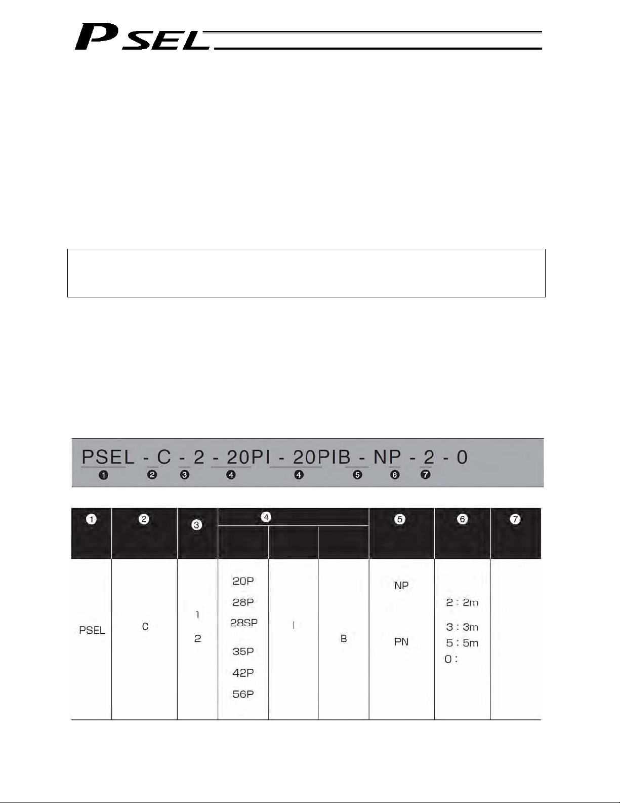
Refer to the following table for details on type specification.
Example of type specification
Type specification table
Series
Controller
type
(Standard
specification)
Number
of axes
(Axis 1)
(Axis 2)
Motor
output (W)
(22, square)
(28, square)
(RCP2RA3C, square)
(35, square)
(42, square)
(56, square)
Details of axis 1 to axis 2
Encoder
type
(Incremental)
Brake
Blank
(Without
brake)
(With brake)
Standard
I/O
Standard PIO
24 inputs/8
outputs
NPN specification
Standard PIO
24 inputs/8
outputs
PNP specification
I/O flat cable
length
(Standard)
None
Powersource
voltage
0: 24 VDC
9
Page 20

Part 1 Installation
3. PSEL Controller Functions
The functions provided by the PSEL controller are structured in the following manner.
The PSEL controller has the “program mode” in which SEL programs are input to operate the actuator(s),
and the “positioner mode” in which position numbers are specified from the host PLC to operate the
actuator(s).
The positioner mode provides five sub-modes to meet the needs of various applications.
The program mode has been selected at the factory prior to the shipment of the controlle r (Other
parameter No. 25 = 0).
Caution: Two modes cannot be selected at the same time.
Program mode
Positioner mode
Standard mode
Product switching mode
2-axis independent mode
Teaching mode
DS-S-C1 compatible mode
10
Page 21

Part 1 Installation
This controller can be configured with one axis and two axes. Just like other conventional SEL controllers,
this controller can be combined with various actuators. When connecting an actuator, be sure to use a
dedicated cable.
Turn on the I/O power before or simultaneously with the main power (control power + motor powe r).
Take the control power and motor power from the same power supply and turn on both powers
simultaneously.
Before performing a check or inserting/removing a connector, turn off the power and wait for at least 10
minutes. Even after the power is turned off, the internal circuits will continue to carry high voltages for a
short period.
About actuator duty
IAI recommends that our actuators be used at a duty of 50% or less as a guideline in view of the
relationship of service life and precision:
Duty (%) =
Inactivity time Motion
Time onDecelerati / onAccelerati
X 100
After turning off the control power, be sure to wait for at least 5 seconds before turning it back on.
Do not insert or remove connectors while the controller power is on. Doing so may cause malfunction.
Read the operation manual for each actuator. If you have purchased our optional PC software and/or
teaching pendant, read the respective operation manuals, as well.
* Utmost effort has been made to ensure that the information contained in this manual is true and
correct. However, should you find any error or if you have any comment regarding the content,
please contact IAI.
11
Page 22
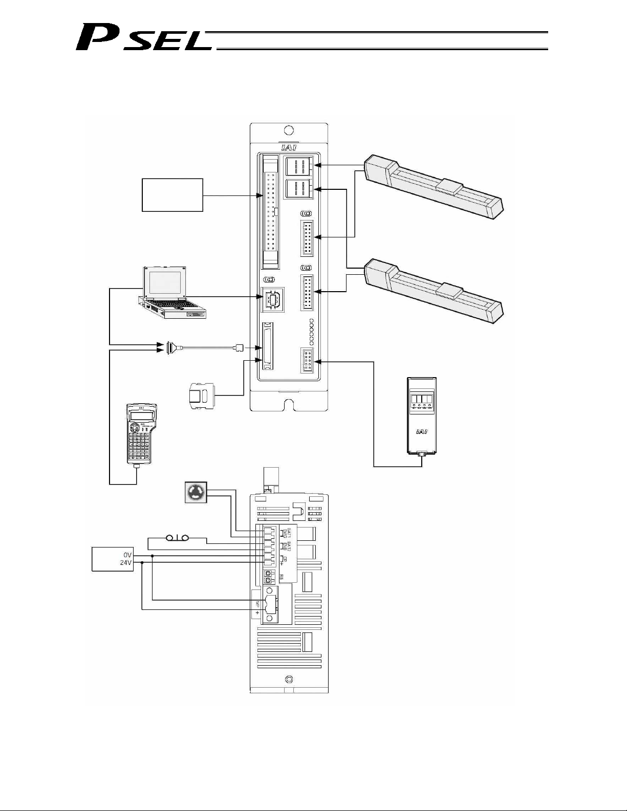
4. System Setup
24-VDC
power
supply
Host system
Teaching
pendant
Enable switch
Conversion cable
Dummy plug
Emergency stop
switch
Part 1 Installation
Panel unit
12
Page 23

Part 1 Installation
5. Warranty Period and Scope of Warranty
The PSEL Controller you have purchased passed our strict outgoing inspection. This unit is covered by
the following warranty:
1. Warranty Period
The warranty period shall be either of the following periods, whichever ends first:
18 months after shipment from our factory
12 months after delivery to a specified location
2. Scope of Warranty
Should the product fail during the above period under a proper use condition du e to a fault on the part
of the manufacturer, IAI will repair the defect free of charge. However, the following cases are
excluded from the scope of warranty:
Discoloration of paint or other normal aging
Wear of consumable parts due to use
Subjective imperfection, such as noise not affecting mechanical function
Defect caused by inappropriate handling or use by the user
Defect caused by inappropriate or erroneous maintenance/inspection
Defect caused by use of a part other than IAI’s genuine part
Defect caused by unauthorized modification, etc., not approved by IAI or its agent
Defect due to an act of God, accident, fire, etc.
The warranty covers only the product as it is delivered. IAI shall not be liable for any loss arising in
connection with the delivered product. The user must bring the defective product to our factory to
receive a warranty repair.
3. Scope of Service
The price of the delivered product does not include costs incurred in association with program
generation, dispatch of technician, etc. Therefore, a separate fee will be chargeable in the following
cases even during the warranty period:
Guidance on installation/adjustment and witnessing of test operation
Maintenance/inspection
Technical guidance and training on operation, wiring method, etc.
Technical guidance and training regarding programs, such as program generation
Other services and operations where IAI finds a need to charge a separate fee
13
Page 24

Chapter 2 Specifications
1. Controller Specifications
Base specifications of this product
Total output when maximum
number of axes are connected
Control power input
Motor power input
Resistance against
momentary power failure
Withstand voltage
Isolation resistance
Drive-source cutoff method Internal relay
Emergency stop input Contact B inp ut (Internal power-supply type)
Emergency stop action Deceleration stop + Regenerative brake by timer
Enable input Contact B input (Internal power-supply type)
Position detection method Incremental encoder of A/B two-phase output type
Battery
Programming language Super SEL language
Number of program steps 2000 steps (total)
Number of positions 1500 positions (total)
Number of programs 64 programs
Multi-tasking capability 8 programs
Storage device Flash ROM
Data input method Teaching pendant or PC software
PIO power input
Safety category Category B (Built-in relay)
PIO inputs 24 points, NPN or PNP (Selectable as factory setting)
PIO outputs 8 points, NPN or PNP (Selectable as factory setting)
Air cooling method Natural convection method
Weight 440 g
External dimensions 43 (W) x 159 (H) x 110 (D); mounting pitch 151 mm
Accessories
30 W x 2 axes
24 VDC 10%
24 VDC 10%
Maximum 0.5 msec
1500 VAC for 1 minute (Measured between all power-supply terminals
and FG)
500 VDC, 10 M or more
System-memory backup battery (Optional)
Lithium battery: AB-5 by IAI, 3.6 V/2000 mAh
24 VDC 10%
I/O flat cable
Motor power connector
Control power & system I/O connector
Part 1 Installation
14
Page 25
Part 1 Installation
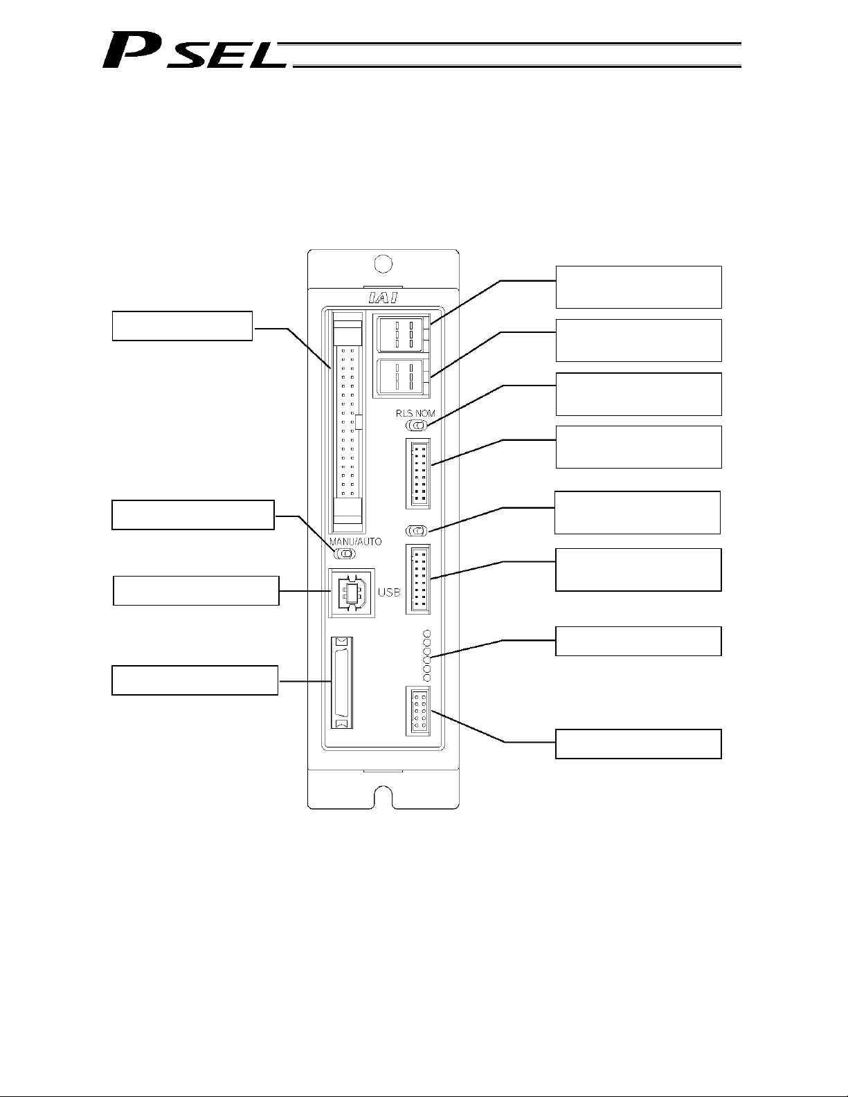
2. Name and Function of Each Part
2.1 Name of Each Part
2.1.1 Front View
[9] PIO connector
[10] MANU/AUTO switch
[11] USB connector
[12] Teaching connector
*1 For the 1-axis specification, [2], [5] and [6] are not installed and the front panel is masked.
[1] Axis 1 motor
connector
[2] Axis 2 motor
connector
[3] Axis 1 brake-release
switch
[4] Axis 1 encoder
connector
[5] Axis 2 brake-release
switch
[6] Axis 2 encoder
connector
[7] LED indicators
[8] Panel unit connector
15
Page 26
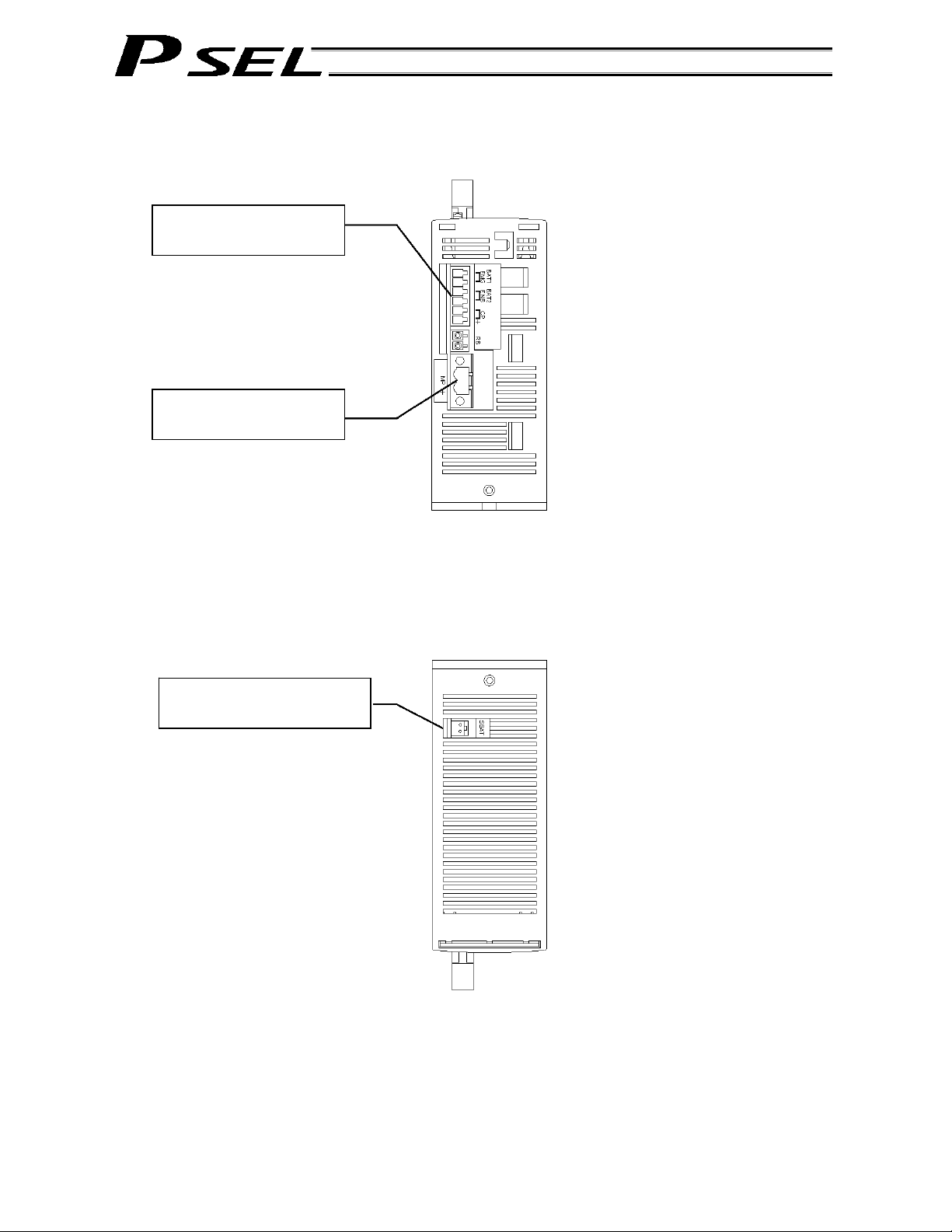
2.1.2 Down View
[14] Control power &
system I/O connector
[15] Motor power
connector
2.1.3 Top View
[13] System-memory backup
battery connector
Part 1 Installation
16
Page 27

Part 1 Installation
[1] Axis 1 motor connector (M1): This connector is used to connect the motor cable for axis 1.
Motor Connector Specifications
Item Specification Remarks
Applicable
connector
AMP Dynamic
D2100, 6 pins
Cable-end
connector
0-1376136-1 (AMP)
0-1318119-3 (AMP)
Contact: 1318107-1 (AMP)
Connector name M1
Maximum
connection distance
20 m
Connected unit Actuator (motor)
Connected cable Motor cable AWG22 X 6C
Motor cable
Controller end
Actuator end
CN2 pin assignments CN1 pin assignments
Cable color Signal symbol Pin No.
Blue
Black
White
Red
Black
Green (yellow 3)
Housing
Receptacle contact
Pin No. Signal symbol Cable color
Red
Black
Blue
Green (yellow 3)
Black
White
Housing
Socket contact
(JST)
[2] Axis 2 motor connector (M2): This connector is used to connect the motor drive-source cable for
axis 2. The specifications are the same as those of the axis 1 motor
connector.
[3] Axis 1 brake-release switch
(BK1):
This switch is used to forcibly release the electromagnetic brake of
the actuator constituting axis 1.
RLS (left) NOM (right)
Name Description
RLS Supply the power to the brake and forcibly release the brake.
NOM
Turn the brake ON/OFF using an internal sequence.
Normally this switch is set to the “NOM” side.
17
Page 28
Part 1 Installation
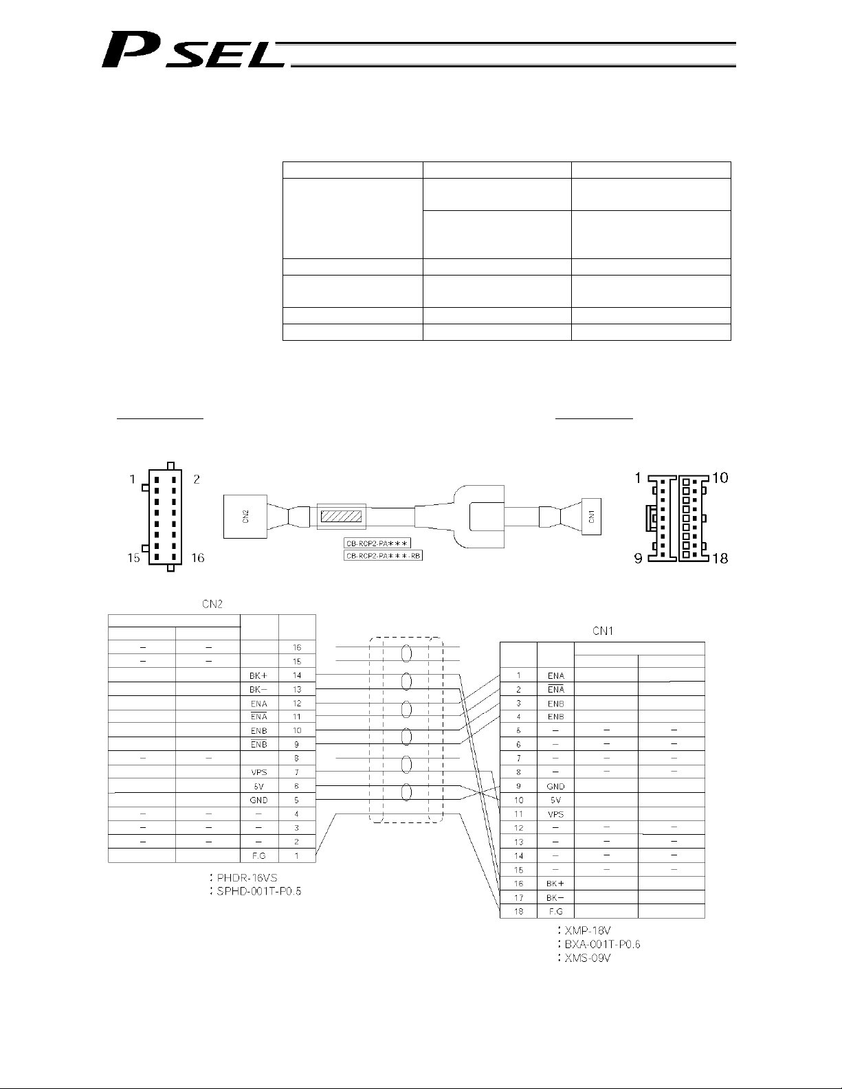
[4] Axis 1 encoder/sensor
connector (PG1):
This connector is used to connect the encoder cable for axis 1. It
connects the encoder cable of the actuator constituting axis 1.
Encoder Connector Specifications
Item Specification Remarks
Applicable connector
2-mm pitch, doublerow connector, 16 pins
S16B-PHDSS (JST)
Cable-end connector PHDR-16VS (JST)
Contact:
SPHD-001T-P0.5 (JST)
Connector name PG1
Maximum connection
distance
20 m
Connected unit Actuator encoder
Connected cable Motor cable AWG22 X 6P Shielded
Encoder cable
Controller end
Actuator end
CN2 pin assignments CN1 pin assignments
Standard cable:
Robot cable:
White (with purple)
White (with yellow)
Cable color
Robot cable
Purple
Blue
White (with blue)
Yellow
Green
Red
White (with red)
Ground
Standard cable
Red
Gray
Brown
Green
Purple
Pink
Yellow
Orange
Blue
Ground
Contact
Retainer
Signal
Pin No.
symbol
(Reserved)
(Reserved)
(Reserved)
(JST)
Pin No.
Housing
Contact
Retainer
symbol
Cable color Signal
Standard cable
Brown
Green
Purple
Pink
Blue
Orange
Yellow
Red
Gray
Ground
(JST)
Robot cable
Blue
White (with blue)
Yellow
White (with yellow)
White (with red)
Red
Green
Yellow
White (with purple)
Ground
18
Page 29

Part 1 Installation
[5] Axis 2 brake-release switch
(BK2):
This switch is used to forcibly release the electromagnetic brake of
the actuator constituting axis 2. The specifications are the same as
those of the axis 1 brake-release switch in [3].
[6] Axis 2 encoder/sensor
connector (PG2):
This connector is used to connect to the encoder cable for axis 2.
The specifications are the same as those of the axis 1
encoder/sensor connector in [4].
[7] LED indicators: These indicators indicate the controller status.
Name Color Status when the LED is lit
PWR
RDY Green The controller is ready.
ALM Orange
EMG Red An emergency stop is being actuated.
SV1 Green The servo for axis 1 is on.
SV2 Green The servo for axis 2 is on.
Green
The controller has been started successfully and is
receiving power.
An alarm is present (an error of message level or
higher has generated.)
[8] Panel unit connector: This connector is used to connect the optional panel unit.
[9] PIO connector: This 34-pin, flat DIO connector consists of 24 inputs and eight
outputs.
Standard I/O Interface Specifications (key items)
Item Description
Connector name I/O
Applicable connector Flat connector, 34 pins
Power supply
Inputs
Outputs
Connected to External PLC, sensor, etc.
Power is supplied from connector pin Nos. 1
and 34.
24 points (including general-purpose inputs and
dedicated inputs)
8 points (including general-purpose outputs and
dedicated outputs)
19
Page 30

I/O Interface List (Program mode)
Pin No. Category Port No. Function Cable color
1A - External power supply 24 V 1-Brown
1B 016
2A 017
2B 018
3A 019
3B 020
4A 021
4B 022
5A 023
5B 000
6A 001
6B 002
7A 003
7B 004
8A 005
8B 006
9A 007
9B 008
10A 009
10B 010
11A 011
11B 012
12A 013
12B 014
13A
13B 300
14A 301
14B 302
15A 303
15B 304
16A 305
16B 306
17A
17B N External power supply 0 V 4-Yellow
Input
Output
Program specification (PRG No. 1) 1-Red
Program specification (PRG No. 2) 1-Orange
Program specification (PRG No. 4) 1-Yellow
Program specification (PRG No. 8) 1-Green
Program specification (PRG No. 10) 1-Blue
Program specification (PRG No. 20) 1-Purple
Program specification (PRG No. 40) 1-Gray
Software reset (restart) 1-White
Program start 1-Black
General-purpose input 2-Brown
General-purpose input 2-Red
General-purpose input 2-Orange
General-purpose input 2-Yellow
General-purpose input 2-Green
General-purpose input 2-Blue
General-purpose input 2-Purple
General-purpose input 2-Gray
General-purpose input 2-White
General-purpose input 2-Black
General-purpose input 3-Brown
General-purpose input 3-Red
General-purpose input 3-Orange
General-purpose input 3-Yellow
General-purpose input 3-Green
015
Alarm output 3-Blue
Ready output 3- Purple
Emergency-stop output 3-Gray
General-purpose output 3-White
General-purpose output 3-Black
General-purpose output 4-Brown
General-purpose output 4-Red
General-purpose output 4-Orange
307
The above functions reflect the factory settings for the program mode.
These functions can be changed by changing the corresponding pa rameters.
Part 1 Installation
20
Page 31

Part 1 Installation
[10] MANU/AUTO switch: This switch is used to specify the controller operation mode.
MANU AUTO
(left) (right)
Teaching pendant/PC software operation
(when the TP connector is used)
PC software operation (when the USB
connector is used)
Starting of an auto start program Not possible Possible
MANU AUTO
Possible Not possible
Possible
Note)
Not possible
Note) When this switch is set to the “MANU” side and the USB
connector is used, the servo cannot be turned on unless a
dummy plug or teaching pendant is connected to the TP
connector. When the USB connector is used, always keep
a dummy plug or PC software cable connected to the TP
plug while the controller is in use. (This is to cancel the
disabled condition.)
If a dummy plug is used, always operate the controller in a
condition where the emergency stop switch is within an
easy reach.
[11] USB connector: This connector is used to connect the PC software and the
controller via a USB cable.
Connector: USB connector B (XM7B-0442)
Connected to: USB cable
The maximum USB cable length is 5 m.
Notes
When the USB port is used, you must connect all required controllers one by one while installing
the USB driver included in the “X-SEL PC Software IA-101-X-USB” CD-ROM. For information on
how to install the driver, refer to the Operation Manual for X-SEL PC Software.
When the USB port is used, a dummy plug must be plugged into the teaching connector [12].
Dummy plug model: DP-3
21
Page 32

[12] Teaching connector
(TP):
The teaching interface connects IAI’s teaching pendant or a PC (PC
software) to enable operation and setting of your equipment from the
teaching pendant/PC.
The interface is a RS232C system based on a 26-pin, half-pitch I/O
connector. The signal level conforms to RS232C, and a desired baud rate
(maximum 115.2 kbps) can be selected based on the program. This
connector can be used only when the mode switch is set to “MANU.”
Interface Specifications of Teaching Serial Interface
Item Description Details
26-pin, half-pitch
I/O connector
Mating connector TX20A-26PH1-D2P1-D1E (by JAE)
TX20A-26R-D2LT1-A1LHE (by JAE) Connector
Part 1 Installation
Connector
name
Baud rate Up to 115.2 kbps Half-duplex communication speeds of
Maximum wiring
distance
Interface
standard
Connected unit Dedicated teaching
Connection
cable
Power supply 5 VDC or 24 VDC A multi-fuse (MF-R090) is installed to
Protocol X-SEL teaching
Emergency-stop
control
Enabling control Enable switch line
T.P. Teaching connector
up to 115.2 kbps are supported.
10M At 38.4 kbps
RS232C
IAI’s standard IA-T-X (D) for X-SEL
pendant
Dedicated cable
protect each line against short current
(the fuse will trip with currents of
between 1.1 A and 2.2 A).
The connector supports the X-SEL
protocol
Series
emergency-stop
relay drive (24 V)
(24 V)
teaching pendant interface protocol.
An emergency-stop relay drive line is
provided in the interface connector. This
line is connected in series with other
emergency-stop contact.
A line for connecting an enable switch is
provided as an operator interlock.
22
Page 33

Teaching pendant & dedicated communication cable connecto r
Item Specification Remarks
Pin No. I/O Signal name
1 SG Signal ground
2 Out EMGS Emergency-stop status
3 Out VCC Power output (Standard IA-T-X/XD power supply (5 V))
4 In DTR Data terminal ready (Shorted to DSR)
5 NC Not connected
6 NC Not connected
7 NC Not connected
Power output (ANSI compliant IA-T-XA power supply
(24 V))
Power output (ANSI compliant IA-T-XA power supply
(24 V))
Clear to send (Not used / Used as the TP-connection
detection terminal)
Terminal
assignments
8 Out RSVVCC
9 In EMGIN Emergency-stop contact output, negative
10 Out RSVVCC
11 NC Not connected
12 Out EMGOUT2 Emergency-stop contact output, positive
13 Out RTS Request to send (Not used; fixed to 0 V)
14 In CTS
15 Out TXD Transmitted data
16 In RXD Received data
17 Out DSR Data set ready (Shorted to DTR)
18 NC Not connected
19 NC Not connected
20 NC Not connected
21 NC Not connected
22 NC Not connected
23 In ENBTB Enable input
24 Out ENBVCC Enable drive power (24 V)
25 NC Not connected (Reserved by ENBTBX2)
26 SG Signal ground
Part 1 Installation
23
Page 34

[13] System-memory backup
battery connector:
This connector is used to install the system-memory backup battery.
[14] Control power & system
I/O connector:
This connector is used to input the 24-VDC control power and connect the
emergency stop switch and enable switch.
The power supply connected to this connector is used for the controlle r
internal power, brake power, and so on, and not used as the motor drive
source.
The 0-V input is connected to the ground for the controller’s internal power
supply and is not isolated.
Item Specification Remarks
3.5 mm, 2-piece
COMBICON, 6 pins
Applicable
connector
Connector name CP EMG ENB
Input voltage 24 VDC + 10%/-10%
Maximum input
current
Terminal
assignments
Cable-end connector
Applicable wire size AWG20 ~ 16 (0.5 ~ 1.25 sq)
Recommended
stripped-wire length
1.2 A
No. Name Function
1 EMG+ Emergency stop switch +
2 EMG- Emergency stop switch 3 ENB+ Enable switch +
4 ENB- Enable switch -
5 0 V
6 24 V Control power input +24 V
Part 1 Installation
MC1.5/6-G-3.5 by Phoenix
Contact
MC1.5/6-ST-3.5 by Phoenix
Contact
7 mm
Control power input ground
(Connected to the internal
ground)
24
Page 35

Part 1 Installation
[15] Motor power connector: This connector is used to input the 24-VDC motor power.
The power supply connected to this connector is used as the dedi cated
motor drive source.
Since the controller has a built-in drive-source cutoff relay, the power
supply to the motor will be cut off internally if an emergency stop is
actuated or other abnormality occurs.
Although the motor power and control power are input independently, the
0-V terminals of both are connected inside the controller. They are also
connected to the ground for the controller’s internal power supply and are
not isolated.
Item Specification Remarks
5.08 mm, 2-piece
COMBICON, 2 pins
Applicable
connector
Connector name MP
Input voltage
Maximum input
current
Terminal
assignments
Cable-end connector
Applicable wire size AWG20 ~ 14 (0.5 ~ 2.0 sq)
Recommended
stripped-wire length
24 VDC 10%
4.0 A 2.0 A per axis
No. Name Function
1 0 V
2 24 V Motor power input +24 V
MSTB2.5/2-GF-5.08 by
Phoenix Contact
MSTB2.5/2-STF-5.08 by
Phoenix Contact
7 mm
Motor power input ground
(Connected to the internal
ground)
25
Page 36

Chapter 3 Installation and Wiring
1. External Dimensions
(1) 2-axis specification
(The same external dimensions also apply to the 1-axis specification.)
5
Part 1 Installation
26
Page 37

(2) 2-axis specification with battery
Part 1 Installation
27
Page 38

Part 1 Installation
2. Installation Environment
(1) When installing and wiring the controller, do not block the ventilation holes provided for cooling.
(Insufficient ventilation will not only prevent the product from functioning fully, but it may also result in
failure.)
(2) Prevent foreign matter from entering the controller through the ventilation holes. Since the controller is
not designed as dustproof or waterproof (oilproof), avoid using it in a dusty place or place subject to
oil mist or splashed cutting fluid.
(3) Do not expose the controller to direct sunlight or radiant heat from a high heat source such as a
heat-treating furnace.
(4) Use the controller in a non-condensing environment free from corrosive or inflammable gases.
(5) Use the controller in an environment where it will not receive external vibration or impact.
(6) Prevent electrical noise from entering the controller or its cables.
Environmental Condition of Controller
Item Specification and description
Surrounding air temperature
range
Surrounding humidity range 10% ~ 95% (Non-condensing; conforming to JIS C3502 RH-2)
Storage temperature range
Maximum operating altitude 2000 m
Protection class IP20
Vibration
Impact
0 ~ 40C
-25C ~ 70C (Excluding the battery)
10 f < 57: 0.035 mm (continuous), 0.075 mm (intermittent)
57 f 150: 4.9 m/s
2
(continuous), 9.8 m/s2 (intermittent)
X, Y and Z directions
147 mm/s
2
, 11 ms, half-sine pulse, 3 times each in X, Y and Z
directions
28
Page 39

Part 1 Installation
3. Heat Radiation and Installation
Design the control panel size, controller layout and cooling method so that the surrounding air temperature
around the controller will be kept at or below 40°C.
Install the controller vertically on a wall, as illustrated below. The controller will be cooled by natural
convection. Be sure to install the controller in the aforementioned direction and provide a minimum
clearance of 50 mm above and below the controller.
If multiple controllers are to be installed side by side, providing additional suction fans on top of the
controllers will help maintain a uniform surrounding air temperature.
Provide a minimum clearance of 95 mm between the front side of the controller and a wall (enclo sure).
If multiple controllers are to be connected on top of one another, prevent the controller above from taking
in the exhaust air from the controller below.
Airflow direction
Fan
50 mm min.
95 mm min.
50 mm min.
Airflow
29
Page 40

Part 1 Installation
4. Noise Control Measures and Grounding
The PSEL controller has no dedicated terminal to connect the FG to ground. Accordingly, provide
grounding using the controller mounting screw.
[1] Provide dedicated Class D grounding. The grounding wire should have a size of 2.0 to 5.5 mm
larger.
Controller
Other
equipment
Controller
Other
equipment
Connect a cable of
the largest possible
size over the shortest
possible distance.
Metal
enclosure
Class D grounding Proper grounding Avoid using this method.
[2] Notes on wiring method
Use twisted wires for the 24-VDC external power supply.
Wire the controller cables separately from lines creating a strong electric field such as power circuit lines
(by not bundling them together or placing in the same cable duct).
If you wish to extend the motor cable or encoder cable beyond the length of each supplied cable, please
contact IAI’s Technical Service Section or Sales Engineering Section.
2
or
30
Page 41

Part 1 Installation
(3) Noise sources and noise elimination
There are many noise sources, but solenoid valves, magnet switches and relays are of particular
concern when building a system. Noise from these parts can be eliminated using the measures
specified below:
[1] AC solenoid valve, magnet switch, relay
Measure --- Install a surge killer in parallel with the coil.
Surge killer
Point
Wire from each coil over the shortest distance.
Installing a surge killer on the terminal block, etc.,
will be less effective because of a longer distance
from the coil.
[2] DC solenoid valve, magnet switch, relay
Measure --- Install a diode in parallel with the coil. Determine the diode capacity in accordance with
the load capacity.
In a DC circuit, connecting a diode in reversed polarity will
damage the diode, internal parts of the controller and DC
power supply. Exercise due caution.
Diode
The above noise elimination measures are particularly important when a 24-VDC relay is driven directly by
a controller output and there is also a 100-VAC solenoid valve, etc.
31
Page 42

Reference Circuit Diagram
Controller
OUT
COM
CR
+24 V
0 V
Part 1 Installation
100 VAC
CR
Surge absorber
0 V
Solenoid valve
32
Page 43

5. Supply Voltage
The supply voltage to the controller is 24 VDC 10%.
The power-supply current varies depending on the number of axes, as shown below.
1-axis specification 2-axis specification
[1] Control power-supply curre nt 1.2 A
[2] Rated motor power-input current 1.2 A 2.4 A
[3] Maximum motor power-input current 2.0 A 4.0 A
[4] Rated current ([1] + [2]) 2.4 A 3.6 A
[5] Maximum current ([1] + [3]) 3.2 A 5.2 A
Part 1 Installation
33
Page 44

Part 1 Installation
6. Wiring
6.1 Wiring the Control Power Supply, Emergency Stop Switch and Enable Switch
As shown to the left, insert the stripped end of each
cable into the control power & system I/O connector,
and tighten the screws with a screwdriver.
Recommended cable size: 0.75 mm
Recommended stripped-wire length: 7 mm
Enable switch
Emergency stop switch
24 VDC
2
(AWG18)
34
Page 45

6.2 Wiring the Motor Power Cables
Part 1 Installation
As shown to the left, insert the stripped end of each
cable into the motor power connector, and tighten the
screws with a screwdriver.
2
Recommended cable size: 2 mm
(AWG14)
Recommended stripped-wire length: 7 mm
As shown to the left, tighten the screws to affix the
connector.
24 VDC
35
Page 46

6.3 Connecting the Actuator
6.3.1 Connecting the Motor Cable (M1/M2)
Connect the motor cable from the actuator to the
applicable motor connector on the front face of the
controller.
6.3.2 Connecting the Encoder Cable (PG1/PG2)
Connect the encoder cable from the actuator to the
applicable encoder connector on the front face of the
controller.
Part 1 Installation
36
Page 47

6.4 Connecting the PIO Cable (I/O)
Connect the supplied flat cable. Connect the opposite
end (open end without connector) of the cable to a
desired peripheral (host PLC, etc.).
I/O flat cable (supplied): Model number CB-DS-P10020
No. Color Wire No. Color Wire
1A Brown 1 9B Gray 2
1B Red 1 10A White 2
2A Orange 1 10B Black 2
2B Yellow 1 11A Brown-3
3A Green 1 11B Red 3
3B Blue 1 12A Orange 3
4A Purple 1 12B Yellow 3
4B Gray 1 13A Green 3
5A White 1 13B Blue 3
5B Black 1 14A Purple 3
6A Brown-2 14B Gray 3
6B Red 2 15A White 3
7A Orange 2 15B Black 3
7B Yellow 2 16A Brown-4
8A Green 2 16B Red 4
8B Blue 2 17A Orange 4
9A Purple 2
Flat cable,
pressure-
welded
Part 1 Installation
No connector
Flat cable (34 cores)
Flat cable,
pressure-
welded
17B Yellow 4
37
Page 48

6.4.1 I/O Connection Diagram
(1) NPN specification (Program mode)
Pin No.
Pin No.
Category
The above functions reflect the factory settings.
Output
Category
Input
Port No.
Port No.
Alarm output
Ready output
General-purpose output
External power supply 24 V
Program specification (PRG No. 1)
Program specification (PRG No. 2)
Program specification (PRG No. 4)
Program specification (PRG No. 8)
Program specification (PRG No. 10)
Program specification (PRG No. 20)
Program specification (PRG No. 40)
Software reset (restart)
Program start
General-purpose input
General-purpose input
General-purpose input
General-purpose input
General-purpose input
General-purpose input
General-purpose input
General-purpose input
General-purpose input
General-purpose input
General-purpose input
General-purpose input
General-purpose input
General-purpose input
General-purpose input
Function Cable color
General-purpose output
General-purpose output
General-purpose output
General-purpose output
General-purpose output
External power supply 0 V
Function
3 – Blue
3 – Purple
3 – Gray
3 – White
3 – Black
4 – Brown
4 – Red
4 – Orange
4 – Yellow
Part 1 Installation
Cable color
1 – Brown
1 – Red
1 – Orange
1 – Yellow
1 – Green
1 – Blue
1 – Purple
1 – Gray
1 – White
1 – Black
2 – Brown
2 – Red
2 – Orange
2 – Yellow
2 – Green
2 – Blue
2– Purple
2 – Gray
2 – White
2 – Black
3 – Brown
3 – Red
3 – Orange
3 – Yellow
3 – Green
38
Page 49

(2) PNP specification (Program mode)
Pin No.
Category
Input
Pin No. Category
Port No.
Output
The above functions reflect the factory settings.
Port No.
External power supply 24 V
Program specification (PRG No. 1)
Program specification (PRG No. 2)
Program specification (PRG No. 4)
Program specification (PRG No. 8)
Program specification (PRG No. 10)
Program specification (PRG No. 20)
Program specification (PRG No. 40)
Software reset (restart)
Program start
General-purpose input
General-purpose input
General-purpose input
General-purpose input
General-purpose input
General-purpose input
General-purpose input
General-purpose input
General-purpose input
General-purpose input
General-purpose input
General-purpose input
General-purpose input
General-purpose input
General-purpose input
Function Cable color
Alarm output
Ready output
General-purpose output
General-purpose output
General-purpose output
General-purpose output
General-purpose output
General-purpose output
External power supply 0 V
Function
3 – Blue
3 – Purple
3 – Gray
3 – White
3 – Black
4 – Brown
4 – Red
4 – Orange
4 – Yellow
Part 1 Installation
Cable color
1 – Brown
1 – Red
1 – Orange
1 – Yellow
1 – Green
1 – Blue
1 – Purple
1 – Gray
1 – White
1 – Black
2 – Brown
2 – Red
2 – Orange
2 – Yellow
2 – Green
2 – Blue
2– Purple
2 – Gray
2 – White
2 – Black
3 – Brown
3 – Red
3 – Orange
3 – Yellow
3 – Green
39
Page 50

g
)
(3) NPN specification (Standard positioner mode)
Pin No.
Pin No..
Category
Output
Category
Port No.
Standard mode
Position input 10
Position input 11
Position input 12
Position input 13
Start
Input
Port No
Home return
Servo ON Servo ON
Push motion Push motion
* Pause * Pause
* Cancellation
Interpolation Interpolation
Position input 1
Position input 2
Position input 3
Position input 4
Position input 5
Position input 6
Position input 7
Position input 8
Position input 9
Standard mode
* Alarm * Alarm
Ready
Positioning complete
Home return complete
Servo ON output
Push motion complete Push motion complete
System battery error System battery error
Model switching
mode
Input 10
Input 11
Input 12
Input 13
Input 14
Input 15
Input 16
Error reset Error reset
Start
Home return
* Cancellation
Input 1
Input 2
Input 3
Input 4
Input 5
Input 6
Input 7
Input 8
Input 9
Model switching
mode
Ready Ready Ready
Positioning complete Positioning complete Positioning complete
Home return complete Home return complete
Servo ON output
0-V input
Positioner mode
2-axis independent
mode
24-V input
Position input 7
Position input 8
Position input 9
Position input 10
Position input 11
Position input 12
Position input 13
Axis 1 start
Home return
Axis 1 servo ON
* Axis 1 pause
* Axis 1 cancellation
Axis 2 start
Axis 2 home return
Axis 2 servo ON
* Axis 2 pause
* Axis 2 cancellation
Position input 1
Position input 2
Position input 3
Position input 4
Position input 5
Position input 6
Positioner mode
2-axis independent
mode
* Alarm
Axis 1 positioning
complete
Axis 1 home return
complete
Axis 1 servo ON
Axis 2 positioning
complete
Axis 2 home return
complete
Axis 2 servo ON
Teaching mode
Axis 1 jog
Axis 1 jog
Axis 2 jog
Inching (0.01 mm)
Inching (0.1 mm)
Inching (0.5 mm)
Inchin
(1 mm
Error reset Error reset
Start Start
Servo ON
* Pause
Position input 1
Position input 2
Position input 3
Position input 4
Position input 5
Position input 6
Position input 7
Position input 8
Position input 9
Position input 10
Position input 11
Teaching mode
specification
Axis 1 jog+
Teaching mode
* Alarm
Servo ON output
System battery error System battery error
compatible mode
Alarm
Ready
CD-S-C1
compatible mode
Position No. 1000 input
CPU reset
Pause
Cancellation
Interpolation setting
Position No. 1 input
Position No. 2 input
Position No. 4 input
Position No. 8 input
Position No. 10 input
Position No. 20 input
Position No. 40 input
Position No. 80 input
Position No. 100 input
Position No. 200 input
Position No. 400 input
Position No. 800 input
CDC-S-C1
*: Contact B (always ON)
Part 1 Installation
Cable
color
1 – Brown
1 – Red
1 – Orange
1 – Yellow
1 – Green
1 – Blue
1 – Purple
1 – Gray
1 – White
1 – Black
2 – Brown
2 – Red
2 – Orange
2 – Yellow
2 – Green
2 – Blue
2– Purple
2 – Gray
2 – White
2 – Black
3 – Brown
3 – Red
3 – Orange
3 – Yellow
3 – Green
Cable
color
3 – Blue
3 – Purple
3 – Gray
3 – White
3 – Black
4 – Brown
4 – Red
4 – Orange
4 – Yellow
40
Page 51

g
)
(4) PNP specification (Standard positioner mode)
Pin No..
Category
Port No.
Standard mode
Model switching
mode
Position input 10
Position input 11
Position input 12
Position input 13
Input
Start
Home return
Servo ON Servo ON
Push motion Push motion
* Pause * Pause
* Cancellation
Interpolation Interpolation
Position input 1
Position input 2
Position input 3
Position input 4
Position input 5
Position input 6
Position input 7
Position input 8
Position input 9
Input 10
Input 11
Input 12
Input 13
Input 14
Input 15
Input 16
Error reset Error reset
Start
Home return
* Cancellation
Input 1
Input 2
Input 3
Input 4
Input 5
Input 6
Input 7
Input 8
Input 9
Pin No..
Category
Output
Port No.
Standard mode
* Alarm * Alarm
Ready
Positioning complete
Home return complete
Servo ON output Servo ON output
Push motion complete Push motion complete
System battery error System battery error
Model switching
Ready Ready Ready
Positioning complete Positioning complete
Home return complete Home return complete
Positioner mode
mode
Positioner mode
2-axis independent
mode
24-V input
Position input 7
Position input 8
Position input 9
Position input 10
Position input 11
Position input 12
Position input 13
Axis 1 start
Home return
Axis 1 servo ON
* Axis 1 pause
* Axis 1 cancellation
Axis 2 start
Axis 2 home return
Axis 2 servo ON
* Axis 2 pause
*Axis 2 cancellation
Position input 1
Position input 2
Position input 3
Position input 4
Position input 5
Position input 6
2-axis independent
mode
* Alarm
Axis 1 positioning
complete
Axis 1 home return
complete
Axis 1 servo ON
Axis 2 positioning
complete
Axis 2 home return
complete
Axis 2 servo ON
0-V input
Teaching mode
Axis 1 jog
CD-S-C1
compatible mode
Position No. 1000 input
Axis 1 jog
Axis 2 jog
Inching (0.01 mm)
Inching (0.1 mm)
Inching (0.5 mm)
Inchin
1 mm
Error reset Error reset
CPU reset
Start Start
Servo ON
* Pause
Position input 1
Position input 2
Position input 3
Position input 4
Position input 5
Position input 6
Position input 7
Position input 8
Position input 9
Position input 10
Position input 11
Teaching mode
specification
Axis 1 jog+
Teaching mode
* Alarm
Pause
Cancellation
Interpolation setting
Position No. 1 input
Position No. 2 input
Position No. 4 input
Position No. 8 input
Position No. 10 input
Position No. 20 input
Position No. 40 input
Position No. 80 input
Position No. 100 input
Position No. 200 input
Position No. 400 input
Position No. 800 input
DC-S-C1
compatible mode
Alarm
Ready
Positioning
Servo ON output
System battery error System battery error
*: Contact B (always ON)
Part 1 Installation
Cable
color
1 – Brown
1 – Red
1 – Orange
1 – Yellow
1 – Green
1 – Blue
1 – Purple
1 – Gray
1 – White
1 – Black
2 – Brown
2 – Red
2 – Orange
2 – Yellow
2 – Green
2 – Blue
2– Purple
2 – Gray
2 – White
2 – Black
3 – Brown
3 – Red
3 – Orange
3 – Yellow
3 – Green
Cable
color
3 – Blue
3 – Purple
3 – Gray
3 – White
3 – Black
4 – Brown
4 – Red
4 – Orange
4 – Yellow
41
Page 52

6.5 External I/O Specifications
6.5.1 NPN Specification
(1) Input part
External Input Specifications (NPN Specification)
Item Specification
Input voltage
Input current 7 mA per circuit
ON/OFF voltage
Isolation method Photocoupler isolation
External devices
Internal circuit
24 VDC 10%
ON voltage --- 16.0 VDC min.
OFF voltage --- 5.0 VDC max.
[1] No-voltage contact (minimum load of approx. 5 VDC/1 mA)
[2] Photoelectric/proximity sensor (NPN type)
[3] Sequencer transistor output (open-collector type)
[4] Sequencer contact output (minimum load of approx. 5 VDC/1 mA)
* P24: I/O interface pin No. 1
[Input circuit]
560
3.3 k
P24*
Input terminal
Part 1 Installation
+
External power
supply 24 VDC 10%
-
Caution
If a non-contact circuit is connected externally, malfunction may result from leakage
current. Use a circuit in which leakage current in a switch-off state does not exceed 1
mA.
PSEL controller’s input signal
At the default settings, the system recognizes the ON/OFF durations of input signals if they
are approx. 4 msec or longer. The ON/OFF duration settings can also be changed using I/O
parameter No. 20 (input filtering frequency).
42
ON duration
OFF duration
Page 53

(2) Output part
External Output Specifications (NPN Specification)
Item Specification
Load voltage 24 VDC
Maximum load current 100 mA per point, 400 mA per 8 ports Note)
Leakage current 0.1 mA max. per point
Isolation method Photocoupler isolation
External devices
Note) 400 mA is the maximum total load current of output port Nos. 300 to 307.
[1] Miniature relay
[2] Sequencer input unit
[Output circuit]
Internal circuit
D
10
P24*
Surge absorber
Output terminal
N*
* P24: I/O interface pin No. 1A
* N: I/O interface pin No. 17B
Part 1 Installation
TD62084 (or equivalent)
Load
External power supply
24 VDC 10%
Caution
In the event that the load is short-circuited or current exceeding the maximum load
current is input, the overcurrent protection circuit will be actuated to cut off the circuit.
However, give due consideration to the circuit connection layout to prevent short-circuit
or overcurrent.
43
Page 54

6.5.2 PNP Specification
(1) Input part
External Input Specifications (PNP Specification)
Item Specification
Input voltage
Input current 7 mA per circuit
ON/OFF voltage
Isolation method Photocoupler isolation
External devices
Internal circuit
Part 1 Installation
24 VDC 10%
ON voltage --- 8 VDC max.
OFF voltage --- 19 VDC min.
[1] No-voltage contact (minimum load of approx. 5 VDC/1 mA)
[2] Photoelectric/proximity sensor (PNP type)
[3] Sequencer transistor output (open-collector type)
[4] Sequencer contact output (minimum load of approx. 5 VDC/1 mA)
[Input circuit]
Input terminal
+
External power
560
3.3 k
N*
supply 24 VDC 10%
-
* N: I/O interface pin No. 17B
Caution
If a non-contact circuit is connected externally, malfunction may result from leakage
current. Use a circuit in which leakage current in a switch-off state does not exceed 1
mA.
PSEL controller’s input signal
At the default settings, the system recognizes the ON/OFF durations of input signals if they
are approx. 4 msec or longer. The ON/OFF duration settings can also be changed using I/O
parameter No. 20 (input filtering frequency).
44
ON duration
OFF duration
Page 55

(2) Output part
External Output Specifications (PNP Specification)
Item Specification
Load voltage 24 VDC
Maximum load current 100 mA per point, 400 mA per 8 ports Note)
Leakage current 0.1 mA max. per point
Isolation method Photocoupler isolation
External devices
Note) 400 mA is the maximum total load current of output port Nos. 300 to 307.
[1] Miniature relay
[2] Sequencer input unit
[Output circuit]
Internal circuit
10
Output terminal
P24
Surge absorber
Load
N
* P24: I/O interface pin No. 1A
* N: I/O interface pin No. 17B
Part 1 Installation
TD62784 (or equivalent)
+
External power supply
24 VDC 10%
-
Caution
In the event that the load is short-circuited or a current exceeding the maximum load
current is input, the overcurrent protection circuit will be actuated to cut off the circuit.
However, give due consideration to the circuit connection layout to prevent short-circuit
or overcurrent.
45
Page 56

6.6 Connecting the Teaching Pendant/PC (Software) (TP) (Optional)
The PSEL controller’s teaching connector (TP) is a
small, half-pitch connector. If you are using a teaching
pendant or PC software cable, connect the cable to a
connector conversion cable, and then connect the
conversion cable to the teaching connector on the
controller.
6.7 Connecting the Panel Unit (Optional)
When the optional panel unit is connected, the
controller status (program number of each active
program, error codes, etc.) can be monitored.
Part 1 Installation
46
Page 57

Part 1 Installation
6.7.1 Explanation of Codes Displayed on the Panel Unit (Optional)
(1) Application
Display Priority (*1) Description
1 Control power cut off
1 System-down level error
2 Writing data to the flash ROM.
3 Emergency stop is being actuated (except during the update mode).
4 Enable switch (deadman switch/safety gate) OFF (except in the update mode)
5 Cold-start level error
5 Cold-start level error
5 Operation-cancellation level error
5 Operation-cancellation level error
6 Waiting for a drive-source cutoff reset input (except during the update mode).
6 Operation is in pause (waiting for restart) (except during the update mode).
7 All servo axes are interlocked (except during the update mode).
8 Message level error
8 Message level error
9 Core update mode
9 Core update is in progress.
9 Core update has completed.
9 Slave update mode
9 Slave update is in progress.
9 Slave update has completed.
9 Running a program (last started program); “No.” indicates program number.
9 Initialization sequence number
9 Debug mode
(*1) The priority increases as the number decreases.
47
Page 58

Part 1 Installation
Display Priority (*1) Description
9 Ready status (auto mode) (Program mode)
9 Ready status (manual mode) (Program mode)
9 Operating in positioner mode; “No.” indicates positioner mode number.
9 Ready status (auto mode) (Positioner mode)
9 Ready status (manual mode) (Positioner mode)
(*1) The priority increases as the number decreases.
48
Page 59

(2) Core
Display Priority (*1) Description
1 Control power cut off
1 Cold-start level error
1 Cold-start level error
1 Operation-cancellation level error
1 Operation-cancellation level error
2 Message level error
2 Message level error
2 Application update mode
2 Application update is in progress.
Part 1 Installation
2 Application update has completed.
2 Hardware test mode process
2 Clearing the application flash ROM.
2 Application flash ROM has been cleared.
2 Jump to the application
2 Core flash-ROM check process
2 Application flash-ROM check process
2 SDRAM check process
(*1) The priority increases as the number decreases.
49
Page 60

Part 1 Installation
6.7.2 Current Monitor and Variable Monitor
By setting other parameter Nos. 49 and 50 appropriately, the optional panel unit can be used to monitor
either current levels or variables.
(1) Current monitor
Currents of up to four axes having continuous axis numbers can be monitored.
Parameter settings
Other parameter No. 49 = 1
Other parameter No. 50 = Smallest axis number among the axes to be monitored
Example) If other parameter No. 49 is set to “1” and other parameter No. 50 to “1” for a 2-axis controller,
the far-right segment digit will show the current for axis 1.
Axis 2 Axis 1
When data is written to the flash ROM or a software reset (restart) is executed after the parameter values
have been input, the panel window will show the motor current to rating ratio (%) by a segment pattern,
instead of “ready status” or “program run number.”
The segment display patterns and corresponding motor current to rating ratios (%) are shown below.
0 < Motor current to rating ratio (%) 25
25 < Motor current to rating ratio (%)
50 < Motor current to rating ratio (%)
75 < Motor current to rating ratio (%)
Thick lines indicate illuminated segments.
50
75
100
100 < Motor current to rating ratio (%) 150
150 < Motor current to rating ratio (%) 200
200 < Motor current to rating ratio (%)
50
Page 61

Part 1 Installation
(2) Variable monitor
The contents of global integer variables can be displayed on the panel window.
Positive integers of 1 to 999 can be displayed.
Parameter settings
Other parameter No. 49 = 2
Other parameter No. 50 = Variable number of the global integer variable to be monitored
When data is written to the flash ROM or a software reset (restart) is executed after the parameter values
have been input, the panel window will show the content of the global integer variable, instead of “ready
status” or “program run number.” The far-left segment digit should read “U.”
Display example)
51
Page 62

6.8 Installing the System-memory Backup Battery (Optional)
As shown to the left, install the supplied battery
holder on the left side face of the controller.
Insert the battery into the holder.
Connect the battery connector.
Pay attention to the connector orientation.
(The connector hook should face the right side.)
Part 1 Installation
52
Page 63

Part 1 Installation
Chapter 4 Operation
1. Startup
(1) Connect the motor cable and encoder cable to the controller.
(2) Connect the PIO connector to the host PLC using the supplied flat cable.
(3) Execute an emergency stop.
(4) Connect the PC or teaching pendant.
Set the AUTO/MANU switch to the “MANU” side.
(5) Supply the 24-V PIO power through the flat cable.
(6) Turn on the control power and motor power at the same time. (They should be taken from the same
power supply.)
(7) Reset the emergency stop.
The EMG lamp turns off.
If the ALM lamp is lit, an error is present. Check the error list to identify the problem.
If the 24-V PIO power is not supplied, an “E69” error will generate.
To check for errors, connect the teaching pendant, PC software or panel unit.
53
Page 64

Part 1 Installation
1.1 Power ON Sequence
Although separate inputs are provided for the control power and motor powe r, they should be supplied
from the same power-supply terminal.
Turn on the PIO power first. You can turn on the PIO power much earlier than the control power and
motor power, as long as it is turned on before the control power/motor power.
Taken from the
same power supply.
The PIO power must be turned on
before the control power, in order
to perform checks during
initialization and self-diagnosis and
apply a hardware latch upon
detection of an error.
Control power
Motor power
Controller status
PIO power
Must be turned
on first, as a
rule.
Must be turned on
simultaneously, as a rule.
Initialization/self-diagnosis
Normal operating condition
* If the PIO power is not turned on before the control power is turned on, an error will be detected.
1.2 Power Cutoff Sequence
If the PIO power is turned off before the control power and motor power (before the power cutoff
processing is performed), a PIO power error may be logged internally by the controller.
The PIO power can be turned off much later than the control power and motor power, as long as it is
turned off after the control power/motor power.
Control power
Motor power
Controller status
PIO power
If the PIO power is
turned off during this
period, an error may
be logged internally by
the controller.
Must be turned off
simultaneously, as a rule.
Once the control power
drops to approx. 19 V or
below, the power cutoff
processing is started.
Power cutoff processing
54
Page 65

Part 1 Installation
2. How to Use the Simple Absolute Unit (Optional)
2.1 How to Connect the Simple Absolute Unit (Optional)
Connect the controller, simple absolute unit (optional) and actuator as shown in the figure below. For
details on the simple absolute unit, refer to the “Simple Absolute Unit Operation Manual.”
(Note) The connector for the dedicated harness of the simple absolute unit comes in two types: RCA
actuator type and RCP2 actuator type. Connect the dedicated harness of the simple absolute unit
to the RCP2 actuator connector.
PSEL controller
Simple absolute unit
Dedicated harness
Encoder cable
Actuator
Simple absolute unit
Dedicated harness
Encoder cable
Actuator
Simple absolute unit RCP2 actuator connector
55
Page 66

Part 1 Installation
2.2 Setting the Piano Switches for the Simple Absolute Unit (Optional)
Set the piano switches for the simple absolute unit (optional). For details, refer to the “Simple Absolute
Unit Operation Manual.”
* Set the piano switches with the battery disconnected.
Connect the battery after changing the piano switch settings.
(Refer to 2.2.1, “Names” for the location of the piano switches.)
Setting Switches
These switches are used to set the rotation speed and select the update mode.
(The order of the switches is 1, 2, 3 and 4 from the top.)
Switch Function
1 Rotation speed setting switch 1
2 Rotation speed setting switch 2
3 Update mode selector switch (Keep this switch in the OFF position.)
4 Model selector switch (Keep this switch in the ON position.)
[Rotation Speed Setting Switch]
If the motor reaches or exceeds the specified rotation speed while the controller power is OFF, the
absolute data will be lost and an absolute encoder error will occur. Four setting levels are available, where
a lower motor speed results in a longer data retention time.
Switch
1 2
OFF OFF 100 20 days
ON OFF 200 15 days
OFF ON 400 10 days (initial setting)
ON ON 800 5 days
Note 1) The battery retention times are based on use of a new battery and no change in coordinates at
normal temperature. Use these values only as a guide.
Note 2) The default settings are OFF for switch 1 and ON for switch 2 (= 400 rpm).
[Update Mode Selector Switch]
Switch
3
ON Update mode
OFF Normal condition (default)
In the update mode, the RDY/ALM LED blinks in green/red.
[Model Selector Switch]
Switch
4
ON Keep this switch in the ON position (default).
OFF -
Motor rotation speed (rpm) Battery retention time (guide)
Function
Function
56
Page 67

Part 1 Installation
2.3 Setting the Parameters
To use the simple absolute unit (optional), set the following parameters as specified below. For
information on how to change the parameters, refer to the “X-SEL PC Software Operation Manual”:
Axis-specific Parameter No. 38, “Encoder ABS/INC type” : Set to “1” (ABS).
Axis-specific Parameter No. 46, “ABS unit use selection” : Set to “1” (Use).
2.4 Absolute Reset Method
Perform an absolute reset in the following conditions:
[1] The simple absolute unit has been connected to the PSEL controller for use for the first time.
[2] The actuator encoder cable has been disconnected and then reconnected from/to the PSEL controller.
[3] Error No. 41C, “ABS unit encoder error (2)” or 41D, “ABS unit encoder error (3)” has occurred.
[4] One of the parameters relating to home return or axis operation (Axis-specific Parameter Nos. 1, 6,
10, 11, 12, 21, 38, 42, 43, 44, 46, 47, 50, 51, 66, 67, 68 and Driver Parameter No. 26) has been
changed or otherwise the home position may have been changed.
Perform an absolute reset using the “X-SEL PC software” by following the procedure below:
(1) Supply the main power (24 VDC) to the controller and simple absolute unit.
When no other adjustment is required other than “ABS unit encoder error (2),” the 7-segment LED
should show “E41C” if the panel unit is connected.
(2) Connect the X-SEL PC software online (by connecting the controller and PC using a dedicated
communication cable).
(3) When the [Connection Check] dialog box appears, set the baud rate according to the corresponding
setting on the PC you are using. Click the [OK] button. (The baud rate need not be set, because the
appropriate baud rate is recognized automatically.)
57
Page 68

Part 1 Installation
(4) The X-SEL PC software window opens. If an error has been detected, an error message appears.
Click the [OK] button to close the error message. If “ABS unit encoder error (2)” has been detected,
the following error message appears:
(5) You can check the condition of the present error by clicking [Monitor (M)] and then selecting [Error
Details (E)]. If “ABS unit encoder error (2)” is present, the following window appears (a simple
absolute unit is used for axis 1 in this example). After checking the condition, close the [Error Details]
window.
58
Page 69

(6) From the menu, click [Controller (C)] and then select [Absolute Reset (A)].
(7) When the [Warning] window appears, click the [OK] button.
(8) The [Absolute Reset] window appears.
Click here
to select the axis which is the target of absolute reset.
1
Part 1 Installation
59
Page 70

Part 1 Installation
(9) Click the following process buttons in this order. When each process is completed, the red arrow
moves to the next item:
[1] Reset Controller Error
[2] Turn OFF Servo
[3] Initialize Simple ABS Unit Condition
[4] Clear Excitation Detection Completed Status
[5] Turn ON Servo
[6] Home Return
[7] Absolute Reset
[8] Confirm Completion of Absolute Reset
After the [Initialize Simple ABS Unit Condition] button has been clicked, the warning diagram box
appears to alert you that an absolute reset will commence. Click the [Yes (Y)] button.
When a confirmation screen appears again, click the [Yes (Y)] button.
When the [Confirm Completion of Absolute Reset] process has completed, the red arrow returns to
the condition shown in (8). If you want to perform an absolute reset for a different axis, select the
target axis here and then perform the processes after (8). To end the procedure, click the [Close]
button to close the [Absolute Reset] window.
(Note) To perform an absolute reset for multiple axes, complete steps (8) and (9) for all axes
before performing the software reset in step (10) below.
60
Page 71

Part 1 Installation
(10) When the software reset [Confirmation] dialog box appears, click the [Yes (Y)] button to restart the
controller.
(Note) After an absolute reset, be sure to perform a software reset.
(11) As long as no error is present after the restart, the 7-segment LED should show “rdy” if the panel unit
is connected.
(12) This completes the absolute reset.
61
Page 72

Part 1 Installation
3. How to Start a Program
With the PSEL Controller, the stored programs can be started (run) using four methods. Of these methods,
two are mainly used to debug programs or perform trial operations, while the remaining two are u se d in
general applications on site.
The former two methods are “starting from the teaching pendant” and “starting from the PC software.”
These methods provide simple means of checking the operation. For detail s on “starting from the teaching
pendant,” read the operation manual for the optional teaching pendant. For “starting from the PC
software,” read the applicable explanation in the manual supplied with the PC software.
The latter two methods are “starting automatically via parameter setting” and “starting via external signal
selection.” This chapter only explains the methods for “starting automatically via parameter setting” and
“starting via external signal selection.”
Teaching pendant
PC software
Start
Start
PSEL
Controller
Start
Starting
automatically via
parameter setting
Starting via
external signal
selection
62
Page 73

3.1 Starting a Program by Auto-Start via Parameter Setting
Other parameter No. 7 (Auto program start setting) = 1 (Standard factory setting)
This parameter is set using the teaching pendant or PC software.
Set an auto-start program number
Set the number of the program you wish to start
automatically in other parameter No. 1 (auto-start
program number).
Set the controller mode to AUTO.
Reset the controller
Reconnect the power or execute a software reset, and
the controller will be reset.
Automatically starting the program
Once the controller is reset in the above step, the
program of the set number will start automatically.
*
Part 1 Installation
Caution
[Note on starting a program by auto-start]
The automatic operation will begin immediately after the controller is reset, so the user may be surprised
by unexpected movements of the equipment, particularly those caused by a sudden activation of the servo
actuator. To ensure safety, always provide an interlocking function, such as allowing the prog ram
execution to proceed only after receiving a confirmation signal at the beginning of the program.
If you wish to start multiple programs at the same time, write multiple “EXPG” commands at the beginning
of the main program to start the remaining programs. Provide safety measures for each program to be
started.
* If the following setting is performed, the program of the selected program number will start
automatically at the ON edge of the signal received by the selected input port. The program will be
aborted at the OFF edge.
You can set a desired input port for receiving the auto program start signal (dedicated function).
Set the input function setting value “5” in the I/O parameter corresponding to the desired input port
number (Nos. 30 through 45, 251 through 258).
(Refer to “I/O Function Lists” and “I/O Parameters.”)
63
Page 74

3.2 Starting via External Signal Selection
(1) Flow chart
Select a desired program number externally and then input a start signal.
External device
Power ON
READY signal
Various I/O
processing
Program number
specification
Start signal ON
Emergency-stop
switch ON?
Emergency-stop
signal ON
ALARM signal
processing
Controller
error?
Controller
Power ON
READY signal
ON
Program number
confirmed?
Start signal
confirmed?
Program run
Emergency-stop
signal confirmed?
Servo OFF
ALARM signal
ON
Ready output
Program number
input
External start input
Emergency-stop
input
Alarm output
confirmed?
confirmed?
ALARM
Part 1 Installation
When the READY signal (Output port No.
301) turns ON, the RDY lamp (green) on the
controller front panel will illuminate.
Input a desired program number as a BCD
code from the external device (Input port
Nos. 16 through 22).
Input a start signal (input port No. 0) from the
external device.
If the optional panel unit is connected, the
CODE display area indicates the program
number of each program that has been
started.
If an emergency-stop signal was input from
the external device or a controller error
occurred, the controller will turn off the servo
power. (The RDY lamp will turn off.)
Note) The assignments of dedicated
input/output port functions (such
as RDY output start signal) reflect
the factory settings.
64
Page 75

A
A
(2) Timing chart
[1] Starting a program
Ready output
Program
number input
External start
input
[2] Starting a program by auto start
* Set the input function specification value “5” (auto program start signal) for input port No. *.
Ready output
uto start
program signal
input
uto program
start
[3] Soft reset signal
* Set the input function specification value “3” (soft reset signal) for input port No. *.
Ready output
Soft reset
signal input
Program
starting
[4] Servo ON signal
* Set the input function specification value “4” (servo ON signal) for input port No. *.
Ready output
Servo ON
signal input
Servo ON
Program 1 Program 2
Part 1 Installation
T1: Duration after the ready output turns ON until input of
external start signal is permitted
T1 = 10 msec min.
T2: Duration after the program number is input until input
of external start signal is permitted
T2 = 50 msec min.
T3: Input duration of external start signal
T3 = 100 msec min.
T1: Time after the ready output turns ON until the auto
start program signal can be input to input port No. *.
T1 = 10 msec min.
* Auto program start:
Set “0” for the auto start program setting of the other
parameter No. 7.
T1: Time after the ready output turns ON until the input
function specification value “3” (soft reset signal) can
be input to input port No. *.
T1 = 10 msec min.
T2: Time until the soft reset signal starts functioning.
T2 = 1 sec min.
T3: Time after the soft reset signal is cancelled until the
ready signal is output.
T1: Time after the ready output turns ON until the input
function specification value “4” (servo ON signal) can
be input
T1 = 10 msec min.
T2: Interval after the servo turns OFF until it turns ON
again
T2 = 1.5 sec min.
Warning: If the servo is turned on near the mechanical end, excited phase detection may not be
performed properly and an excited pole indetermination error or excited pole detection
error may generate.
Move the slider, rod, etc., away from the mechanical end before turning on the servo.
65
Page 76

[5] When the recovery type after emergency stop or enable operation is set to “Operation continued”
* Set other parameter No. 10 to “2” and set the input function specification value “7” (operation-pause reset signal) for
input port No. *.
Set the input function specification value “17“ (drive-source cutoff reset input signal) for other input port No. *.
Program
starting
Emergency
stop
Drive-source
cutoff reset
Pause reset
T1: Time after the emergency stop input is reset until the
drive-source cutoff reset signal can be input
T1 = 2 sec min.
T2: Drive-source cutoff reset input time
T1 = 10 msec min.
T3: Pause reset input time
T1 = 10 msec min.
Part 1 Installation
66
Page 77

Part 1 Installation
4. Drive-Source Recovery Request and Operation-Pause Reset Request
(1) Drive-source recovery request
[1] Case where a drive-source request is required
A drive-source recovery request is required in the following case:
Specify a desired input port for receiving the drive-source cutoff reset input signal (dedicated
function).
Occurrence of a drive-source cutoff factor Recovery after the cutoff factor is removed.
[2] How to request a drive-source recovery
A drive-source recovery request can be issued using one of the following methods:
Set the input function specification value “17” in the I/O parameter corresponding to the
desired input port number (Nos. 30 through 45, 251 through 258). (Refer to “I/O Function
Lists” and “I/O Parameters.”)
Input the ON edge to the input port of the specified number.
Select [Drive-Source Recovery Request (P
software screen.
Select Ctl (controller operation) and RPwr (drive-source recovery request) on the mode
selection screen of the teaching pendant.
(2) Operation-pause reset request
[1] Cases where an operation-pause reset request is required
An operation-pause reset request is required in any of the following cases:
An emergency stop was actuated during automatic operation when other parameter No. 10
was set to “2” (Emergency-stop recovery type = Continued operation) (only during automatic
operation) Recovery (reset of operation pause) after the emergency stop is reset.
The automatic operation was stopped using the deadman switch or enable switch when other
parameter No. 11 was set to “2” (Deadman/enable switch recovery type = Contin ued
operation) (only during automatic operation) Recovery (reset of operation pause) after the
stop is reset.
Specify a desired input port for receiving the operation-pause input signal (dedicated
function). Set the input function specification value “8” in the I/O parameter corresponding to
the desired input port number (Nos. 30 through 45, 251 through 258). (Refer to “I/O Function
Lists” and “I/O Parameters.”)
OFF level signal input is received by the import port of the specified number during auto
operation (operations pause) Recovery after detection of ON signal level by the input port
(operation pause is reset).
[2] How to request an operation-pause reset
An operation-pause reset request can be issued using one of the following methods:
Specify a desired input port for receiving the operation-pause input signal (dedicated
function). Set the input function specification value “7” in the I/O parameter corresponding to
the desired input port number (Nos. 30 through 45, 251 through 258). (Refer to “I/O Function
Lists” and “I/O Parameters.”)
Input the ON edge to the input port of the specified number.
Select [Operation-Pause Reset Request (L)] from the [Controller (C)] menu on the PC
software screen.
Select Ctl (controller operation) and RAct (operation-pause reset request) on the mode
selection screen of the teaching pendant.
* If the case in [1] of (1) and any of the cases in [1] of (2) are present at the same time, a
drive-source recovery request must be issued first, followed by an operation-pause reset request.
)] from the [Controller (C)] menu on the PC
67
Page 78

Part 1 Installation
5. Controller Data Structure
The controller data consists of parameters as well as position data and application programs used to
implement SEL language.
PSEL Controller Data Structure
Parameters
The user must create position data and application programs. The parameters are predefined, but their
settings can be changed in accordance with the user’s system.
Refer to Appendix, “List of Parameters,” for details on the parameters.
Main
SEL language
Position
data
Application
programs
68
Page 79

Part 1 Installation
5.1 How to Save Data
The flow to save data in the PSEL controller is illustrated below.
When data is transferred from the PC software or teaching pendant to the controller, the data is only
written to the main CPU memory as shown in the diagram below and will be erased once the controller is
powered down or reset.
For important data, always write to the flash memory so that they will not be lost.
5.1.1 Factory Settings: When the System-Memory Backup Battery is Not Used
Other parameter No. 20 = 0 (System-memory backup battery not installed)
Data edited on the PC
or teaching pendant
Data will be retained while the power
is on and cleared upon reset
Main CPU memory
Transfer
Programs
Parameters (other than
encorder parameters)
Symbols
Positions
Write to flash memory
Transfer upon reset
PC
software,
TP
Transfer
Encoder parameters
Transfer
Transfer upon reset
SEL global data (flags,
variables, strings)
Error lists
Since the programs, parameters and symbols are read from the flash memory at restart, the data in the
temporary memory will remain the same as the original data before edit unless the edited data are written
to the flash memory.
The controller always operates in accordance with the data in the main CPU memory (excluding the
parameters).
Note: SEL global data cannot be retained if the backup battery is not installed.
SEL global data will be cleared once the control power is turned off or a software reset is
executed.
The error list will be cleared once the control power is turned off.
Data will be retained even after
the power is turned off
Main CPU flash memory
Slave card memory
69
Page 80

Part 1 Installation
5.1.2 When the System-Memory Backup Battery (Optional) is Used
Change the setting of other parameter No. 20 to 2 (System-memory backup battery installed).
Data edited on the PC
or teaching pendant
Data will be retained while the power
is on and cleared upon reset
Main CPU memory
Transfer
Programs
Parameters (other than
encorder parameters)
Symbols
Write to flash memory
Transfer upon reset
PC
software,
TP
Transfer
Encoder parameters
Transfer
Transfer upon reset
Transfer
Since the programs, parameters and symbols are read from the flash memory at restart, the data in the
temporary memory will remain the same as the original data before edit unless the edited data are written
to the flash memory.
The controller always operates in accordance with the data in the main CPU memory (excluding the
parameters).
Data will be retained even after
the power is turned off
Main CPU flash memory
Slave card memory
Battery backup memory
Positions
SEL global data (flags,
variables, strings)
Error lists
70
Page 81

Part 1 Installation
5.2 Points to Note
Point to note when transferring data and writing to the flash memory
Never turn off the main power while data is being transferred or written to the
flash memory. The data will be lost and the controller operation may be
disabled.
Point to note when saving parameters to a file
The encoder parameters are stored in the EEPROM of the actuator’s encoder itself (unlike
other parameters, they are not stored in the EEPROM of the controller). The encoder
parameters will be read from the encoder’s EEPROM to the controller when the power is
turned on or upon software reset.
Therefore, if the parameters are saved to a file after turning on the controller (or restarting it
via a software reset) without an actuator (encoder) connected, the enco der parameters saved
to the file will become invalid.
Point to note when transferring a parameter file to the controller
When a parameter file is transferred to the controller, the encoder parameters will be
transferred to the EEPROM of the encoder (excluding manufacturing/function information).
Therefore, if the parameter file transferred to the controller has been read from a controller
that was started without an actuator connected, invalid encoder parameters will be written to
the encoder’s EEPROM (provided that an actuator is connected to the controller to which the
file was transferred).
When saving the parameters to a file, do so with an actuator connected to the controller.
71
Page 82

Part 1 Installation
Chapter 5 Maintenance
Routine maintenance and inspection are necessary so that the system will operate properly at all
times. Be sure to turn off the power before performing maintenance or inspection.
The standard inspection interval is six months to one year. If the environment warrants, however, the
interval should be shortened.
1. Inspection points
Check to see if the supply voltage to the controller is inside the specified range.
Inspect the ventilation holes in the controller and remove dirt, dust and other foreign attachments,
if any.
Inspect the controller cables (controller actuator) and check for any loose screws or cabl e
disconnection.
Check the controller mounting screws, etc., for looseness.
Inspect each cable (axis link cable, general-purpose I/O cable, system I/O cable, power cable) for
loose connection, disconnection, play, etc.
2. Spare consumable parts
Without spare parts, a failed controller cannot be repaired even when the problem is identified quickly. We
recommend that you keep the following consumable parts as spares:
Consumable parts
Cables
System-memory backup battery: (optional): AB-5 by IAI -- Must be replaced after approx. 5 years*
*: The actual replacement timing will vary depending on the use condition. For details, refer to
“ Battery Backup Function” in Appendix.
When the battery voltage drops, an applicable error code will be displayed on the panel windo w.
Error Codes Indicating Low Battery Voltage
System-memory backup battery A01 or A02
72
Page 83

Part 1 Installation
3. Replacement Procedure for System-Memory Backup Battery (Optional)
Backing up the system memory
If the optional system-memory backup battery is installed in the PSEL controller and “Other parameter No.
20: Backup battery installation function type” is set to “2” (Installed), the following SRAM data will be
retained even after the power is turned off:
Position data
SEL global data (flags, integer/real variables, string variables)
Error list
For this reason, always follow the procedure below when replacing the system-memory backup battery:
Note: If the system-memory backup battery is removed while other parameter No. 20, “Backup
battery installation function type” is set to “2 (Installed),” above contents in the SRAM will be
lost.
So that the position data can be restored even after the SRAM data has been cleared, save
the position data to a file using the PC software before removing the battery.
For information on how to save position data to a file, refer to 6, “Position Data Edit Window” in
“Operation Manual for X-SEL PC Software.”
(1) Turn on the controller power.
(2) Record (write down) the current setting of “Other parameter No. 20, Backup-battery installation
function type.” (This will be used when reverting the parameter to its original setting following the
replacement of system-memory backup battery.)
(3) If the PC software is installed in your PC, save the position data to a file using the PC software. The
data will be used as a backup in case the SRAM data saved to the flash ROM fails.
(4) Change “Other parameter No. 20, Backup-battery installation function type” to “1” and transfer the
setting to the controller, and then perform a flash ROM write. (The point data will be saved to the
flash ROM.)
* Confirm that the flash ROM writing process h as completed.
(5) Perform a software reset to restart the controller. (The SEL global data and error lists will be saved to
the special area in the flash ROM.)
(6) When the controller has been restarted, turn off the power.
* Be sure to keep the power on from the start of controller restart until the RDY LED lamp on teh controller
illuminates.
(7) Replace the system-memory backup battery. SRAM data will be lost if steps (1) through (6) are not
performed properly.
73
Page 84

Part 1 Installation
Battery Replacement Procedure
[1] Remove the battery connector and pull out the
battery.
[2] Insert a new battery into the holder and plug in the
battery connector. The connector hook should face
the right side.
(8) When the replacement of system-memory backup battery is complete, confirm that the battery is
installed securely and then turn on the controller power.
(9) Revert “Other parameter No. 20, Backup-battery installation function type” to the value recorded in
step (2), transfer the setting to the controller, and then perform a flash ROM write.
* Confirm that the flash ROM writing process has completed.
(10) Perform a software reset (restart the controller).
(Note) Commencing the operation without first executing a software reset or reconnecting the po wer
may generate the following errors:
Error No. C70: ABS coordinate non-confirmation error
Error No. C6F: Home-return incomplete error
(11) When the controller has been restarted, confirm that the SRAM data have been restored.
74
Page 85

Part 2 Programs
Chapter 1 SEL Language Data
1. Values and Symbols Used in SEL Language
1.1 List of Values and Symbols Used
The various functions required in a program are represented by values and symbols.
Function Global range Local range Remarks
Input port 000 ~ 299 (300)
Output port 300 ~ 599 (300)
Flag 600 ~ 899 (300) 900 ~ 999 (100)
Variable (integer)
Variable (real)
String 300 ~ 999 (700) 1 ~ 299 (299)
Tag number 1 ~ 256 (256)
Subroutine number 1 ~ 99 (99)
Zone number 1 ~ 4 (4)
Pallet number 1 ~ 10 (10)
Axis number 1 ~ 2 (2)
Axis pattern 0 ~ 11
Position number 1 ~ 1500 (1500)
Program number 1 ~ 64 (64)
Step number 1 ~ 2000 (2000)
Task level NORMAL/HIGH (2)
SIO channel number 0 (1)
Wait timer 1
1-shot pulse timer
Ladder timer Local flag (100)
Virtual input port (SEL
system SEL user
program)
Virtual output port (SEL user
program SEL system)
Number of symbol definitions 500
Number of times symbol can
be used in commands
Caution
Variables 99 and 199 are special variables this system uses in operations.
200 ~ 299 (100)
1200 ~ 1299 (100)
300 ~ 399 (100)
1300 ~ 1399 (100)
7000 ~ 7299 (300)
7300 ~ 7599 (300)
2500 (including literals)
Used in common from any
program.
Referenced separately in
each program.
Cleared when the program
is started.
1 ~ 99 (99)
1001 ~ 1099 (99)
100 ~ 199 (100)
1100 ~ 1199 (100)
16 (Number of timers that
can be operated
simultaneously)
Avoid using these two variables for general purposes.
The values in the table represent ranges that can be processed by software.
Items that require physical devices, such as I/O ports and functions relating
to axis number and SIO, will be determined by possible combinations and
models of commercial boards, etc., available for each device application.
Varies depending on the
function.
Varies depending on the
function.
99 is used for IN, INB,
OUT, OUTB, etc.
199 is used for PPUT,
PGET, PARG, etc.
Varies depending on the
function.
Part 2 Programs
75
Page 86

If the optional system-memory backup battery is installed, data of global variables and flags will be
retained even after the controller power is turned off.
(Other parameter No. 20 must be set to “2.” Refer to 4.1.2, “When the System Memory Backup Battery
is Used” in Chapter 4 of Part 1.)
The variables and flags in the local range will be cleared when the program is started.
Ranges of values that can be used in SEL language
Integers and real numbers can be used. However, pay due attention to the following limitations:
(1) Numeric data
The PSEL Controller can handle values of maximum eight digits including a sign and a decimal point.
Integer: -9,999,999 to 99,999,999
Real number: Maximum eight digits including a sign and decimal point, regardless of the size of value
Example) 999999.9, 0.123456, -0.12345
If a floating point is used in operations, the number of valid digits will be limited to seven. Also note
that operations using a floating point are subject to error.
(2) Position data
The input range of position data consists of four integer digits and three decimal digits.
–9999.999 to 9999.999
(The maximum value varies depending on the actuator model.)
If position data are used in internal operations as numeric data (repeated multiplication s and
divisions), the precision of the last digit may decrease.
Consider the above limitations fully when using values. Particularly when the CPEQ command is
used in a comparison operation using real numbers, a match will rarely result. In this case, the CPLE
or CPGE command that looks at the magnitude relationship of two terms must be used.
Part 2 Programs
1.2 I/O Ports
(1) Input ports
Used as input ports for limit switches, sensor switches, etc.
Input number assignment
000 to 023 (standard)
(2) Output ports
Used as various output ports.
Output number assignment
300 to 307 (standard)
76
Page 87

1.3 Virtual I/O Ports
(1) Virtual input ports
Port No. Function
7000 Always OFF
7001 Always ON
7002 Voltage low warning for system-memory backup battery
7003 Abnormal voltage of system-memory backup battery
7004 (For future expansion = Use strictly prohibited)
7005 (For future expansion = Use strictly prohibited)
7006 Top-level system error = Message level error is present
7007 Top-level system error = Operation-cancellation level error is present
7008 Top-level system error = Cold-start level error is present
7009 (For future expansion = Use strictly prohibited)
7010 Drive-source cutoff factor is present (including when waiting for cutoff reset input)
7011
7012
7013
7014 (For future expansion = Use strictly prohibited)
7015 Voltage low warning for axis-1 absolute-data backup battery
7016
7017 Voltage low warning for axis-2 absolute-data backup battery
7018
7019 ~ 7026 (For future expansion = Use strictly prohibited)
7027 ~ 7040 (For future expansion = Use strictly prohibited)
7041 ~ 7070 (For future expansion = Use strictly prohibited)
7071 In AUTO mode
7072 During automatic operation
7073 ~ 7100 (For future expansion = Use strictly prohibited)
7101 Running program No. 01 (including during pause)
~ ~
7164 Running program No. 64 (including during pause)
7165 ~ 7299 (For future expansion = Use strictly prohibited)
Latch signal indicating that all-operation-cancellation factor is present (latch signal for
recognizing 1-shot cancellation factor; latch is cancelled by 7300-ON)
All-operation-pause factor is present (including when waiting for restart switch signal) (Valid
only during automatic operation recognition)
All-servo-axis-interlock factor is present (all-operation-pause factor + interlock input-port
factor)
Abnormal voltage of axis-1 absolute-data backup battery (latched until power-on reset or
software reset)
Abnormal voltage of axis-2 absolute-data backup battery (latched until power-on reset or
software reset)
Part 2 Programs
77
Page 88

(2) Virtual output ports
Port No. Function
Latch cancellation output for a latch signal indicating that all-operation-cancellation factor
7300
is present (7011) (latch is cancelled only when operation-cancellation factor is no longer
present) (7300 will be turned OFF following an attempt to cancel latch.)
7301 ~ 7380 (For future expansion = Use strictly prohibited)
7381 ~ 7399 (For future expansion = Use strictly prohibited)
7400 ~ 7599 (For future expansion = Use strictly prohibited)
Part 2 Programs
78
Page 89

Part 2 Programs
1.4 Flags
Contrary to its common meaning, the term “flag” as used in programming means “memory.” Flags are
used to set or reset data. They correspond to “auxiliary relays” in a sequencer.
Flags are divided into global flags (Nos. 600 to 899) that can be used in all programs, and local flags (Nos.
900 to 999) that can be used only in each program.
Global flags will be retained (backed up by battery) even after the power is turned off.
Local flags will be cleared when the power is turned off.
Flag number 600 ~ 899 Can b e used in all programs “Global flags”
Flag number 900 ~ 999 Used only in each program “Local flags”
Program 1 Program n
BTON 600
Turn on flag 600
(Like this, global flags can be
used to exchange signals.)
WTON 600
Wait for flag 600 to turn ON
BTON 900 BTON 900
(Although the number is the
same, these are local flags and
can exist only in their
respective programs.)
79
Page 90

Part 2 Programs
1.5 Variables
(1) Meaning of variable
“Variable” is a technical term used in software programming. Simply put, it means “a box in which a value
is put.” Variables can be used in many ways, such as putting in or taking out a value and performing
addition or subtraction.
Variable
box 1
Command Operand 1 Operand 2
A variable can be used in many ways, such as:
Putting in a value (1234),
Taking out a value (456), or
Adding a value (+1).
ADD 1 1
If this command is applied to variable box 1, which already contains 2, then 1 will be added to the current
value and 3 will result.
1 is added.
Variable
box 1
(Already contains 2)
80
Page 91

(2) Types of variables
Variables are classified into two types, as follows:
[1] Integer variables
These variables cannot handle decimal places.
[Example] 1234
Integer variable number
Integer variable number
Caution
Integer 99 is a special register this system uses in integer operations.
Variable
200 ~ 299
1200 ~ 1299
1 ~ 99
1001 ~ 1099
Integer variable box
box 1
Can be used in all programs “Global integer variables”
Used only in each program “Local integer variables”
Any value in the range from –9,999,999 to 99,999,999 can be input in
programs.
[2] Real variables
Actual values. These variables can handle decimal places.
[Example] 1234.567
Real variable number
Real variable number
Caution
(Decimal point)
Real variable box
Variable
box 1
300 ~ 399
1300 ~ 1399
100 ~ 199
1100 ~ 1199
Can be used in all programs “Global real variables”
Used only in each program “Local real variables”
Real number 199 is a special register this system uses in real-number
operations. Any value in the range from –99,999.9 to 999,999.9 (eight
digits including a sign) can be input in programs.
Part 2 Programs
1 2 3 4
1234.567
81
Page 92

[3] Variables with “*” (asterisk) (indirect specification)
An “*” (asterisk) is used to specify a variable.
In the following example, the content of variable box 1 will be put in variable box 2. If variable
box 1 contains “1234,” then “1234” will be put in variable box 2.
Command Operand 1 Operand 2
LET 1 1234
Variable
box 1
1 2 3 4
Command Operand 1 Operand 2
Part 2 Programs
1 2 3 4
Put in.
LET 2 *1
Variable
box 2
1 2 3 4
Variable
box 1
1 2 3 4
The above use of variables is called “indirect specification.”
An “*” is also used when indirectly specifying a symbol variable (refer to 1.8, “Symbols”).
Command Operand 1 Operand 2
LET ABC
1
LET BCD 2
ADD ABC *BCD
Put 1 in variable ABC.
Put 2 in variable BCD.
Add the content of variable BCD, or 2, to variable ABC.
(The content of variable ABC becomes 3.)
82
Page 93

Part 2 Programs
1.6 Tags
The term “tag” means “heading.”
Tags are used in the same way you attach labels to the pages in a book you want to reference frequently.
A tag is a destination specified in a jump command “GOTO.”
Command Operand 1
Tag
TAG Tag number (Integer between 1 and 256)
They are used only in each program.
TAG 1
GOTO 1
83
Page 94

Part 2 Programs
1.7 Subroutines
By taking out the parts of a program that are used repeatedly and registering them as “subroutines,” the
same processing can be performed with fewer steps. (A maximum of 15 nest s are accommodated.)
They are used only in each program.
Command Operand 1
EXSR Subroutine number (Integer bet ween 1 and 99; variable is also supported)
Subroutine execution command
Command Operand 1
BGSR Subroutine number (Integer between 1 and 99)
Subroutine start declaration
Command Operand 1
EDSR
Subroutine end declaration
EXSR 1
EXSR 1
EXSR 1
BGSR 1
EDSR
Subroutines
Subroutines are called.
84
Page 95

Part 2 Programs
1.8 Symbols
In the PSEL Controller, values such as variable numbers and flag numbers can be handled as symbols.
For the method to edit symbols, refer to “Editing Symbols” in the operation manual for PSEL teaching
pendant or “Symbol Edit Window” in the operation manual for PSEL PC software.
(1) Supported symbols
The following items can be expressed using symbols:
Variable number, flag number, tag number, subroutine number, program number, position number,
input port number, output port number, axis number, constant
(2) Description rules of symbols
[1] A maximum of nine single-byte alphanumeric characters or underscore starting with an alphabet
(Note: The length of a character-string literal must not exceed eight single-byte characters.)
* Exercise caution that the same ASCII code may be expressed differently between the PC
software and the teaching pendant because of the different fonts used by the two. (The same
applies to character-string literals.)
5Ch --- PC software: Backslash \ (overseas specifications, etc.)
Teaching pendant: Yen mark ¥
7Eh --- PC software: ~
Teaching pendant: Right arrow
[2] Symbols of the same name must not be defined within each function. (The same local symbol
can be used in different programs.)
[3] Symbols of the same name must not be defined within the flag number, input-port number or
output-port number group. (The same local symbol can be used in different programs.)
[4] Symbols of the same name must not be defined within the integer-variable number or
real-variable number group. (The same local symbol can be used in different programs.)
[5] Symbols of the same name must not be defined within the integer constant or real constant
group.
(3) Number of symbols that can be defined: Maximum 500
(4) Number of times symbols can be used in all SEL programs: Maximum 2500 times including
character-string literals
* If symbol is used in all of the input condition, operand 1, operand 2 and output fields, it is deemed
that symbol is used four times in one step.
1.9 Character-String Literals
Character-string literals are used in certain string-operation commands and consist of the portion enclosed
by single quotation marks (‘ ‘) (maximum eight single-byte characters).
With the PC software, single-byte ASCII code characters from 20h to 7Eh (limited to those that can be
input via keyboard) can be used inside the single quotation marks. With the teaching pendant, single-byte
alphanumeric characters and single-byte underscores can be used.
85
Page 96

1.10 Axis Specification
Axes can be specified based on axis number or axis pattern.
(1) Axis numbers and how axes are stated
Each of multiple axes is stated as follows:
Axis number How axis is stated
1 Axis 1
2 Axis 2
The axis numbers stated above can also be expressed using symbols.
Use axis number if you wish to specify only one of multiple axes.
Commands that use axis specification based on axis number
BASE, PPUT, PGET, ACHZ, AXST, PASE, PARG, PRDQ, ECMD (1.5)
Part 2 Programs
86
Page 97

Part 2 Programs
(2) Axis pattern
Whether or not each axis will be used is indicated by “1” or “0.”
(Upper) (Lower)
Axis number Axis 2 Axis 1
Used 1 1
Not used 0 0
[Example] When axes 1 and 2 are used
Axis 2
11
Axis 1
[Example] When axes 2 is used
Axis 2
10 (In this case, the 0s are needed to indicate the position of axis 2.)
Indirect specification of axis pattern in a variable
The axis pattern is considered a binary value, and a converted decimal value is assigned to a variable.
[Example] To perform home return for axis 2 only, you can specify as follows based on axis pattern:
HOME 10
In indirect specification, 10 (binary) is expressed as 2 (decimal), so the same operation can
be specified as follows:
LET 6 2
HOME *6
If you must select and specify multiple axes at the same time, use axis pattern.
Commands that use axis specification based on axis pattern
OFST, GRP, SVON, SVOF, HOME, JFWN, JFWF, JBWN, JBWF, STOP, PTST, PRED
CHVL, PBND, WZNA, WZNO, WZFA, WZFO, MOVD, MVDI, PTRQ
87
Page 98

Part 2 Programs
SEL language consists of a position part (position data = coordinates, etc.) and a command part
(application program).
2. Position Part
As position data, coordinates, speeds, accelerations and decelerations are set and stored.
2000000.000 mm
*1, 2
1 ~ 2000/mmsec
Position No. Axis 1 Axis 2 Speed Acceleration Deceleration
1
2
3
1498
1499
1500
*1 Varies depending on the actuator model.
*2 If speed, acceleration or deceleration is set in the position data, the setting will be given priority over
the corresponding data set in the application program. Leave the position data fields empty if you
wish to enable the corresponding data in the application program.
Priority Speed Acceleration (deceleration)
1 Value of position data set in operand 1 Value of position data set in operand 1
2 Value set by a VEL command Value set by an ACC (DCL) command
3 All-axis parameter No. 11, “Default acceleration”
Values pertaining to a rotating axis are processed in degrees instead of millimeters.
If axis-specific parameter No. 1 (axis operation type) is set to “1” (rotational movement axis (angle
control)) for a given axis, all millimeter values pertaining to that axis (including parameters, etc.) will be
processed in degrees.
If the gear ratio parameters (axis-specific parameter Nos. 50 and 51) are set correctly, the angles
(deg) will represent those of the body of rotation at the end.
Example) Distance 1 mm 1 deg
Speed 1 mm/sec 1 deg/sec
Acceleration/deceleration 1 G = 9807 mm/sec
*2
Standard
0.3 G
(All-axis parameter No. 12, “Default
deceleration”)
2
9807 deg/sec2
*2
Standard
0.3 G
88
Page 99

Part 2 Programs
3. Command Part
The primary feature of SEL language is its very simple command structure. Since the structure is simple,
there is no need for a compiler (to translate into computer language) and high-speed operation is possible
via an interpreter (the program runs as commands are translated).
3.1 SEL language Structure
The table below shows the structure of one command step.
Extension condition
(AND, OR)
Input condition
(I/O, flag)
Command,
declaration
Using a ladder diagram, this is expressed as follows:
Command
Operand 1 Operand 2
(1) The condition before the command is equivalent to “IF ~ THEN…” in BASIC.
Command
Operand 1
IF ~ THEN ELSE
1. If the input condition is satisfied, the command will be executed. If there is an output specification, the
specified output port will be turned ON. If the input condition is not satisfied, the program will proceed
to the next step regardless of the command that follows (e.g., WTON, WTOF). Obviously nothing will
happen at the output port, but caution must be exercised.
2. If no condition is set, the command will be executed unconditionally.
3. To use the condition in reverse logic (so-called “contact b logic” ), add "N" (NOT) to the
condition.
4. The input condition supports input port, output port and flag.
5. The operand 1, operand 2 and output fields can be specified indirectly.
(2) The output field, which follows the command, operand 1 and operand 2 fields, will specify the
following action:
Command
Operand 1
1. In the case of a control command relating to actuator operation, etc., the output will turn OFF the
moment the execution of command is started, and turn ON when the execution is completed. In the
case of a calculation operation command, etc., the output will turn ON if the result corresponds to a
certain value, and turn OFF if not.
2. The output field supports output port and flag.
Command, declaration
Operand 1 Operand 2
Operand 2
Operand 2
Output
(Output port, flag)
Output
Output
To the next step
Output
89
Page 100

3.2 Extension Condition
Conditions can be combined in a complex manner.
AND extension (Ladder diagram)
Condition
Condition
Condition
OR extension
Condition
Condition
AND extension and OR extension
Condition
AND
1
AND
2
3
1
OR
2
AND
1
Part 2 Programs
(SEL language)
Extension
condition
Condition 1
A
A
Extension
condition
O Condition 2 Command
Extension
condition
Condition 1
Input
condition
Condition 2
Condition 3 Command
Input
condition
Condition 1
Input
condition
Command
Command
Command
Command
Operand 1 Operand
2
Operand 1 Operand
2
Command
Operand 1 Operand
2
Operand 1 Operand
2
Command
Operand 1 Operand
2
Output
Output
Output
Condition
2
Condition
3
90
OR
Condition 2
A
O
Condition 3 Command
Operand 1 Operand
2
 Loading...