

Page 1
PCON-SE Controller
Serial Communication Type
Operation Manual
Sixteenth Edition
IAI America Inc.
Page 2

Page 3

Please Read Before Use
Thank you for purchasing our product.
This Operation Manual explains the handling methods, structure and maintenance of this product, among others,
providing the information you need to know to use the product safely.
Before using the product, be sure to read this manual and fully understand the contents explained herein to
ensure safe use of the product.
The CD or DVD that comes with the product contains operation manuals for IAI products.
When using the product, refer to the necessary portions of the applicable operation manual by printing them out
or displaying them on a PC.
After reading the Operation Manual, keep it in a convenient place so that whoever is handling this product can
reference it quickly when necessary.
[Important]
• This Operation Manual is original.
• The product cannot be operated in any way unless expressly specified in this Operation Manual. IAI
shall assume no responsibility for the outcome of any operation not specified herein.
• Information contained in this Operation Manual is subject to change without notice for the purpose of
product improvement.
• If you have any question or comment regarding the content of this manual, please contact the IAI
sales office near you.
• Using or copying all or part of this Operation Manual without permission is prohibited.
• The company names, names of products and trademarks of each company shown in the sentences
are registered trademarks.
Page 4

Page 5

CAUTION
1. Use Environment
ACON controllers can be used in an environment of pollution degree 2 or equivalent.
2. Models of Teaching Pendants and PC Software
New functions have been added to the whole PCON Controller Series.
Since the communication protocol is accordingly changed to the general Modbus method (compatible), the
PC software and teaching pendants used in conventional RCP2 controllers are not compatible.
When using this controller, prepare the following models:
ledoM Remark
PC software
(with RS232C-compatible cables)
PC software
(with USB-compatible communication cables)
Teaching pendant RCM-T, RCM-TD
Simple teaching pendant RCM-E
Data setter RCM-P
3. Recommendation for Backing Up Latest Data
RCM-101-MW
RCM-101-USB
Can also be connected to
conventional RCP2
controllers
This product uses nonvolatile memory to store t he position table and parameters. Normally the memory
will retain the stored data even after the power is disconnected. However, the data may be lost if the
nonvolatile memory becomes faulty.
We strongly recommend that the latest position table and parameter data be backed up so that the data can
be restored quickly when the controller must be replaced for a given reason.
The data can be backed up using the following methods:
[1] Save to a storage medium such as a hard disk using PC software.
[2] Create a position table sheet or parameter sheet and keep a written record of backup.
Page 6

CAUTION
4. Using a Rotary Actuator in the Multi-rotation Specification
Rotary actuators that support the multi-rotation specification let you specify multi-rotation operation or
limited-rotation operation.
4.1 Notes
Pay attention to the setting of the PIO pattern parameter for the controllers listed below.
On the following types of controllers, relative coordinate specification cannot be used in the PIO patterns
specified:
[1] PCON-C/CG: PIO pattern = 5 (User parameter No. 25)
[2] PCON-CY: PIO pattern = 0 (User parameter No. 25)
4.2 Applicable Models
*-lP82-C-NOCP*063-02-P82-I-LBTR-2PCR
Actuator
RCP2-RTCL-I-28P-30-360*
Controller
PCON-SE-28Pl-*
*-lP82-GC-NOCP*063-03-P82-I-LBTR-2PCR
*-lP82-YC-NOCP*063-02-P82-I-LCTR-2PCR
5. Examples of Modbus Protocol
You can download the manual containing examples of using the Modbus protocol from the manual download
page of IAI’ s website:
http://www.iai-robot.co.jp/download/index.html
If you are interested in the brochure, please contact your IAI sales representative.
Page 7

CE Marking
If a compliance with the CE Marking is required, please follow Overseas Standards Compliance Manual
(ME0287) that is provided separately.
Page 8

Page 9

Table of Contents
Safety Guide .................................................................................................................................1
1. Overview ................................................................................................................................9
1.1 Introduction .............................................................................................................................. 9
1.2 Main Features and Functions ................................................................................................ 10
1.3 Differences from Air Cylinders in Control Functions ...............................................................11
1.4 Model Number........................................................................................................................ 13
1.5 System Configuration............................................................................................................. 14
1.6 Procedure from Unpacking to Trial Run Adjustment.............................................................. 16
1.7 Warranty .................................................................................................................................18
1.7.1 Warranty Period
1.7.2
Scope of Warranty
Honoring the Warranty
1.7.3
1.7.4 Limited Liability
1.7.5 Conditions of Conformance with Applicable Standards/Regulations, Etc.,
and Applications
1.7.6 Other Items Excluded from Warranty
2. Specifications.......................................................................................................................20
2.1 Basic Specifications ............................................................................................................... 20
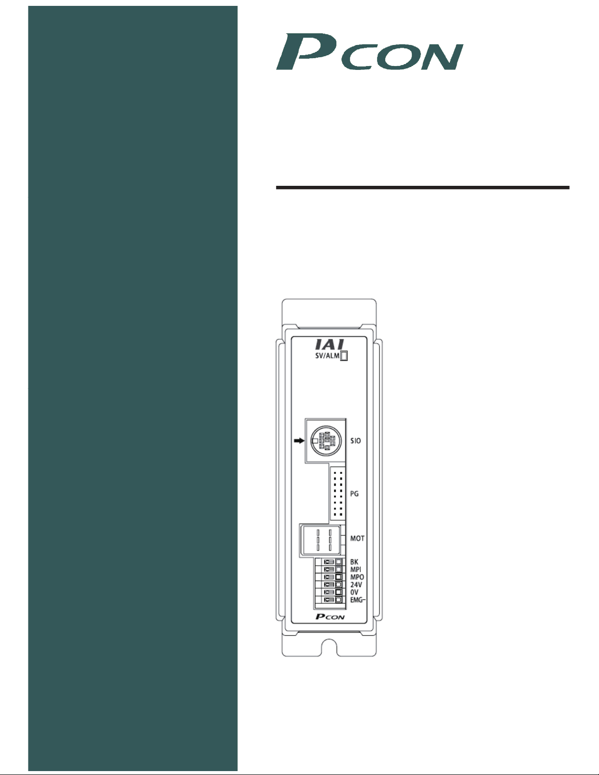
2.2 Name and Function of Each Part of the Controller ................................................................ 21
2.3 External Dimensions .............................................................................................................. 23
2.4 SIO Converter (Option) .......................................................................................................... 24
.......................................................................................................................
...................................................................................................................
...........................................................................................................
........................................................................................................................
......................................................................................................................
...................................................................................
18
18
18
18
19
19
3. Installation and Wiring..........................................................................................................26
3.1 Installation Environment......................................................................................................... 26
3.2 Power Supply ......................................................................................................................... 26
3.3 Noise Elimination and Grounding .......................................................................................... 26
3.4 Heat Radiation and Installation .............................................................................................. 28
3.5 External Connection Diagram ................................................................................................ 29
3.6 Wiring the Power Supply........................................................................................................ 30
3.7 Wiring the Brake Release Switch to Forcibly Release the Brake .......................................... 30
3.8 Wiring the Emergency Stop Circuit ........................................................................................ 31
3.8.1 Drive Signal Shutdown (Standard)............................................................................ 31
(1) When the SIO converter is used .................................................................................31
(2) When the gateway unit is used ...................................................................................32
3.8.2 Cutting off the Motor Drive Power Supply................................................................. 33
(1) When the SIO converter is used .................................................................................33
(2) When the gateway unit is used ...................................................................................34
3.9 Connecting the Actuator.......................................................................................................35
3.9.1 Motor Relay Cable .................................................................................................... 35
3.9.2 Encoder Relay Cable................................................................................................ 36
Page 10

3.10 Connecting the SIO Communication...................................................................................... 37
3.10.1 Connecting the RS232C Serial Communication....................................................... 37
(1) Basic information.........................................................................................................37
3.11 Connection to Field Network .................................................................................................. 41
3.12 Assignment of Axis Number................................................................................................... 41
3.13 Setting the Baud Rate............................................................................................................ 42
4. Description of Operating Functions......................................................................................42
4.1 Description of Position Table.................................................................................................. 44
4.2 Setting Data in Numeric Specification Mode.......................................................................... 48
4.3 Control Signals, Control Data................................................................................................. 49
4.4 Operation Timings.................................................................................................................. 55
4.4.1 Timing after Power ON ............................................................................................. 55
4.4.2 Home Return Operation............................................................................................ 57
4.4.3 Positioning Operation ............................................................................................... 59
4.4.4 Push & Hold Operation ............................................................................................. 63
4.4.5 Pause........................................................................................................................ 71
4.4.6 Speed Change during Movement............................................................................. 72
4.4.7 Operation at Different Acceleration and Deceleration Settings ................................ 74
4.4.8 Zone Signal............................................................................................................... 75
4.4.9 Pitch Feeding by Relative Coordinate Specification ................................................. 76
4.4.10 Power-saving Mode at Standby Positions ................................................................80
4.5 Notes on ROBO Grippers ...................................................................................................... 81
4.6 Using a Rotary Actuator in the Multi-rotation Specification .................................................... 83
(1) Home Return...............................................................................................................83
(2) Operation Commands.................................................................................................83
5. Parameter Settings ..............................................................................................................84
5.1 Parameter Table..................................................................................................................... 84
5.2 Parameter Settings ................................................................................................................ 85
5.2.1 Parameters Relating to the Actuator Stroke Range.................................................. 85
5.2.2 Parameters Relating to the Actuator Operating Characteristics............................... 87
5.2.3 Parameters Relating to the External Interface.......................................................... 94
5.2.4 Servo Gain Adjustment............................................................................................. 96
6. Troubleshooting ................................................................................................................... 98
6.1 Action to Be Taken upon Occurrence of Problem.................................................................. 98
6.2 Alarm Level Classification......................................................................................................
6.3 Alarm Description and Cause/Action ...................................................................................
(1) Operation-cancellation level alarms.........................................................................
(2) Cold-start level alarms ............................................................................................. 103
6.4 Messages Displayed during Operation Using the Teaching Pendant or PC Software ........ 106
6.5 Specific Problems................................................................................................................. 108
99
100
100
7. Operation Examples .......................................................................................................... 112
* Appendix................................................................................................................................. 113
List of Specifications of Connectable Actuators ...............................................................................113
Correlation diagram of speed and loading capacity for the slider type (motor-straight type) ......... 125
Page 11

Correlation diagram of speed and loading capacity for the slider type (motor-reversing type) ...... 126
Correlation diagram of speed and loading capacity for the standard rod type............................... 127
Correlation diagram of speed and loading capacity for the single-guide type................................ 128
Correlation diagram of speed and loading capacity for the double-guide type .............................. 129
Correlation diagram of speed and loading capacity for the dustproof/splash-proof type ............... 130
Correlation diagram of speed and loading capacity for the RCP3 slider type................................ 131
Correlation diagram of speed and loading capacity for the RCP3 table type................................. 132
Push Force and Current-limiting Value ........................................................................................... 133
Position Table Record ..................................................................................................................... 140
Parameter Record........................................................................................................................... 143
Change History ............................................................................................................................... 144
Page 12

Page 13

Safety Guide
“Safety Guide” has been written to use the machine safely and so prevent personal injury or property
damage beforehand. Make sure to read it before the operation of this product.
Safety Precautions for Our Products
The common safety precautions for the use of any of our robots in each operation.
No.
1 Model
Operation
Description
Selection
Description
This product has not been planned and designed for the application where
high level of safety is required, so the guarantee of the protection of
human life is impossible. Accordingly, do not use it in any of the following
applications.
1) Medical equipment used to maintain, control or otherwise affect human
life or physical health.
2) Mechanisms and machinery designed for the purpose of moving or
transporting people (For vehicle, railway facility or air navigation facility)
3) Important safety parts of machinery (Safety device, etc.)
Do not use the product outside the specifications. Failure to do so may
considerably shorten the life of the product.
Do not use it in any of the following environments.
1) Location where there is any inflammable gas, inflammable object or
explosive
2) Place with potential exposure to radiation
3) Location with the ambient temperature or relative humidity exceeding
the specification range
4) Location where radiant heat is added from direct sunlight or other large
heat source
5) Location where condensation occurs due to abrupt temperature
changes
6) Location where there is any corrosive gas (sulfuric acid or hydrochloric
acid)
7) Location exposed to significant amount of dust, salt or iron powder
8) Location subject to direct vibration or impact
For an actuator used in vertical orientation, select a model which is
equipped with a brake. If selecting a model with no brake, the moving part
may drop when the power is turned OFF and may cause an accident such
as an injury or damage on the work piece.
1
Page 14

No.
Operation
Description
Description
2 Transportation When carrying a heavy object, do the work with two or more persons or
utilize equipment such as crane.
When the work is carried out with 2 or more persons, make it clear who is
to be the leader and who to be the follower(s) and communicate well with
each other to ensure the safety of the workers.
When in transportation, consider well about the positions to hold, weight
and weight balance and pay special attention to the carried object so it
would not get hit or dropped.
Transport it using an appropriate transportation measure.
The actuators available for transportation with a crane have eyebolts
attached or there are tapped holes to attach bolts. Follow the instructions
in the operation manual for each model.
Do not step or sit on the package.
Do not put any heavy thing that can deform the package, on it.
When using a crane capable of 1t or more of weight, have an operator
who has qualifications for crane operation and sling work.
When using a crane or equivalent equipments, make sure not to hang a
load that weighs more than the equipment’s capability limit.
Use a hook that is suitable for the load. Consider the safety factor of the
hook in such factors as shear strength.
Do not get on the load that is hung on a crane.
Do not leave a load hung up with a crane.
Do not stand under the load that is hung up with a crane.
3 Storage and
Preservation
The storage and preservation environment conforms to the installation
environment. However, especially give consideration to the prevention of
condensation.
Store the products with a consideration not to fall them over or drop due to
an act of God such as earthquake.
4 Installation
and Start
(1) Installation of Robot Main Body and Controller, etc.
Make sure to securely hold and fix the product (including the work part). A
fall, drop or abnormal motion of the product may cause a damage or injury.
Also, be equipped for a fall-over or drop due to an act of God such as
earthquake.
Do not get on or put anything on the product. Failure to do so may cause
an accidental fall, injury or damage to the product due to a drop of
anything, malfunction of the product, performance degradation, or
shortening of its life.
When using the product in any of the places specified below, provide a
sufficient shield.
1) Location where electric noise is generated
2) Location where high electrical or magnetic field is present
3) Location with the mains or power lines passing nearby
4) Location where the product may come in contact with water, oil or
chemical droplets
2
Page 15

No.
Operation
Description
4 Installation
and Start
Description
(2) Cable Wiring
Use our company’s genuine cables for connecting between the actuator
and controller, and for the teaching tool.
Do not scratch on the cable. Do not bend it forcibly. Do not pull it. Do not
coil it around. Do not insert it. Do not put any heavy thing on it. Failure to
do so may cause a fire, electric shock or malfunction due to leakage or
continuity error.
Perform the wiring for the product, after turning OFF the power to the unit,
so that there is no wiring error.
When the direct current power (+24V) is connected, take the great care of
the directions of positive and negative poles. If the connection direction is
not correct, it might cause a fire, product breakdown or malfunction.
Connect the cable connector securely so that there is no disconnection or
looseness. Failure to do so may cause a fire, electric shock or malfunction
of the product.
Never cut and/or reconnect the cables supplied with the product for the
purpose of extending or shortening the cable length. Failure to do so may
cause the product to malfunction or cause fire.
(3) Grounding
The grounding operation should be performed to prevent an electric shock
or electrostatic charge, enhance the noise-resistance ability and control
the unnecessary electromagnetic radiation.
For the ground terminal on the AC power cable of the controller and the
grounding plate in the control panel, make sure to use a twisted pair cable
with wire thickness 0.5mm
2
(AWG20 or equivalent) or more for grounding
work. For security grounding, it is necessary to select an appropriate wire
thickness suitable for the load. Perform wiring that satisfies the
specifications (electrical equipment technical standards).
Perform Class D Grounding (former Class 3 Grounding with ground
resistance 100 or below).
3
Page 16

No.
4 Installation
Operation
Description
and Start
Description
(4) Safety Measures
When the work is carried out with 2 or more persons, make it clear who is
to be the leader and who to be the follower(s) and communicate well with
each other to ensure the safety of the workers.
When the product is under operation or in the ready mode, take the safety
measures (such as the installation of safety and protection fence) so that
nobody can enter the area within the robot’s movable range. When the
robot under operation is touched, it may result in death or serious injury.
Make sure to install the emergency stop circuit so that the unit can be
stopped immediately in an emergency during the unit operation.
Take the safety measure not to start up the unit only with the power turning
ON. Failure to do so may start up the machine suddenly and cause an
injury or damage to the product.
Take the safety measure not to start up the machine only with the
emergency stop cancellation or recovery after the power failure. Failure to
do so may result in an electric shock or injury due to unexpected power
input.
When the installation or adjustment operation is to be performed, give
clear warnings such as “Under Operation; Do not turn ON the power!” etc.
Sudden power input may cause an electric shock or injury.
Take the measure so that the work part is not dropped in power failure or
emergency stop.
Wear protection gloves, goggle or safety shoes, as necessary, to secure
safety.
Do not insert a finger or object in the openings in the product. Failure to do
so may cause an injury, electric shock, damage to the product or fire.
When releasing the brake on a vertically oriented actuator, exercise
precaution not to pinch your hand or damage the work parts with the
actuator dropped by gravity.
5 Teaching When the work is carried out with 2 or more persons, make it clear who is
to be the leader and who to be the follower(s) and communicate well with
each other to ensure the safety of the workers.
Perform the teaching operation from outside the safety protection fence, if
possible. In the case that the operation is to be performed unavoidably
inside the safety protection fence, prepare the “Stipulations for the
Operation” and make sure that all the workers acknowledge and
understand them well.
When the operation is to be performed inside the safety protection fence,
the worker should have an emergency stop switch at hand with him so that
the unit can be stopped any time in an emergency.
When the operation is to be performed inside the safety protection fence,
in addition to the workers, arrange a watchman so that the machine can
be stopped any time in an emergency. Also, keep watch on the operation
so that any third person can not operate the switches carelessly.
Place a sign “Under Operation” at the position easy to see.
When releasing the brake on a vertically oriented actuator, exercise
precaution not to pinch your hand or damage the work parts with the
actuator dropped by gravity.
* Safety protection Fence : In the case that there is no safety protection
fence, the movable range should be indicated.
4
Page 17

No.
Operation
Description
Description
6 Trial Operation When the work is carried out with 2 or more persons, make it clear who is
to be the leader and who to be the follower(s) and communicate well with
each other to ensure the safety of the workers.
After the teaching or programming operation, perform the check operation
one step by one step and then shift to the automatic operation.
When the check operation is to be performed inside the safety protection
fence, perform the check operation using the previously specified work
procedure like the teaching operation.
Make sure to perform the programmed operation check at the safety
speed. Failure to do so may result in an accident due to unexpected
motion caused by a program error, etc.
Do not touch the terminal block or any of the various setting switches in
the power ON mode. Failure to do so may result in an electric shock or
malfunction.
7 Automatic
Operation
Check before starting the automatic operation or rebooting after operation
stop that there is nobody in the safety protection fence.
Before starting automatic operation, make sure that all peripheral
equipment is in an automatic-operation-ready state and there is no alarm
indication.
Make sure to operate automatic operation start from outside of the safety
protection fence.
In the case that there is any abnormal heating, smoke, offensive smell, or
abnormal noise in the product, immediately stop the machine and turn
OFF the power switch. Failure to do so may result in a fire or damage to
the product.
When a power failure occurs, turn OFF the power switch. Failure to do so
may cause an injury or damage to the product, due to a sudden motion of
the product in the recovery operation from the power failure.
5
Page 18

No.
8 Maintenance
Operation
Description
and Inspection
Description
When the work is carried out with 2 or more persons, make it clear who is
to be the leader and who to be the follower(s) and communicate well with
each other to ensure the safety of the workers.
Perform the work out of the safety protection fence, if possible. In the case
that the operation is to be performed unavoidably inside the safety
protection fence, prepare the “Stipulations for the Operation” and make
sure that all the workers acknowledge and understand them well.
When the work is to be performed inside the safety protection fence,
basically turn OFF the power switch.
When the operation is to be performed inside the safety protection fence,
the worker should have an emergency stop switch at hand with him so that
the unit can be stopped any time in an emergency.
When the operation is to be performed inside the safety protection fence,
in addition to the workers, arrange a watchman so that the machine can
be stopped any time in an emergency. Also, keep watch on the operation
so that any third person can not operate the switches carelessly.
Place a sign “Under Operation” at the position easy to see.
For the grease for the guide or ball screw, use appropriate grease
according to the Operation Manual for each model.
Do not perform the dielectric strength test. Failure to do so may result in a
damage to the product.
When releasing the brake on a vertically oriented actuator, exercise
precaution not to pinch your hand or damage the work parts with the
actuator dropped by gravity.
The slider or rod may get misaligned OFF the stop position if the servo is
turned OFF. Be careful not to get injured or damaged due to an
unnecessary operation.
Pay attention not to lose the cover or untightened screws, and make sure
to put the product back to the original condition after maintenance and
inspection works.
Use in incomplete condition may cause damage to the product or an injury.
* Safety protection Fence : In the case that there is no safety protection
fence, the movable range should be indicated.
9 Modification
and Dismantle
Do not modify, disassemble, assemble or use of maintenance parts not
specified based at your own discretion.
10 Disposal When the product becomes no longer usable or necessary, dispose of it
properly as an industrial waste.
When removing the actuator for disposal, pay attention to drop of
components when detaching screws.
Do not put the product in a fire when disposing of it.
The product may burst or generate toxic gases.
11 Other Do not come close to the product or the harnesses if you are a person
who requires a support of medical devices such as a pacemaker. Doing so
may affect the performance of your medical device.
See Overseas Specifications Compliance Manual to check whether
complies if necessary.
For the handling of actuators and controllers, follow the dedicated
operation manual of each unit to ensure the safety.
6
Page 19
Alert Indication
The safety precautions are divided into “Danger”, “Warning”, “Caution” and “Notice” according to the
warning level, as follows, and described in the Operation Manual for each model.
Level Degree of Danger and Damage Symbol
Danger
Warning
Caution
Notice
This indicates an imminently hazardous situation which, if the
product is not handled correctly, will result in death or serious injury.
This indicates a potentially hazardous situation which, if the product
is not handled correctly, could result in death or serious injury.
This indicates a potentially hazardous situation which, if the product
is not handled correctly, may result in minor injury or property
damage.
This indicates lower possibility for the injury, but should be kept to
use this product properly.
Danger
Warning
Caution
Notice
7
Page 20

8
Page 21

1. Overview
1.1 Introduction
The PCON Series controllers are specifically designed for the RCP2, RCP3 actuators, and adopt new functions to
further enhance convenience and safety by reducing the size and cost while following the functions of the RCP2
controller.
In addition, the power-saving considered function has been adopted, with awareness of energy conservation
raised.
Among the PCON series controllers, this product is designed to operate the actuator via position number
specification or direct numeric specification by means of serial communication.
The serial communication system can support the following two patterns as the serial communication system:
[1] The product can be used under the field network (DeviceNet, CC-Link, Profibus) such as a host PLC as the
gateway unit.
[2] RS-232C serial communication is available with a PC or PLC using the SIO converter.
Before using this product, read this document together with the operation manual for your gateway unit and serial
communication operation manual for your ROBO Cylinder series.
When actually starting the equipment or a failure occurs, refer to the operating manuals of the actuator, teaching
pendant, PC software and other devices in addition to this document.
This Operation Manual does not completely cover all items other than normal operations or unexpected
phenomena such as complicated signal changes by critical timing.
Therefore, interpret any items not covered by this manual as “impossible to do” in principle.
* We have made every effort to ensure precision of the information provided in this manual. Should you find
an error, however, or if you have any comments, please contact IAI.
Keep this manual in a convenient place so it can be reread when necessary.
1. Overview
9
Page 22

1.2 Main Features and Functions
(1) Control signals are input/output via serial communication RS485 (compatible with Modbus protocol).
(2) Positioning points: 64
(3) Setting of zone output boundary values
1. Overview
(4) Separate setting of acceleration and deceleration (only in the operation by position number specification)
(5) Limitation of movement speed during trial run adjustment
(6) Power-saving measure
The zone output boundary values were previously fixedly set with parameters. Convenience has been
enhanced since they can now be set in the position table (only in the operation by position number
specification).
It can be used for the prevention of interference with peripheral equipment or reduction of tact time.
The acceleration and deceleration can separately be set in the position table.
When you do not want to give impact or vibration during stop due to the material or shape of transferred
work, gradual deceleration becomes available by reducing deceleration only.
The movement speed during trial run adjustment can be limited in terms of ensuring safety.
In general, pulse motors require a higher holding current at standstill compared to AC servo motors.
Accordingly, the power-saving mode can be utilized with pulse motors if they are used in applications where
the actuator waits for a long time.
10
Page 23

1.3 Differences from Air Cylinders in Control Functions
For those of you who have been using air cylinders and have never used motorized cylinders before, this section
gives a brief explanation of how this controller is different from air cylinders.
Read the following information and implement controls appropriate for your system.
Item Air cylinder PCON-SE
Drive method Air pressure by solenoid valve
control.
Target position
setting
Target position
detection
Mechanical stopper (including
shock absorber).
Installation of a reed switch or other
external detection sensor.
Speed setting Adjustment by a speed controller.
Acceleration/
deceleration setting
In accordance with the load, air
supply volume, and speed
controller/solenoid valve
performance.
Ball screw or timing belt drive using a pulse motor.
[1] Position number specification mode
Entry of a coordinate value in the “Position” field of
the position table.
A value can be entered by keying in a number from a
PC/teaching pendant, or by moving the actuator to a
desired position and then reading the achieved
position directly.
Example) Example of entry of “400 mm” stroke
Position No. Position
0 5 (mm)
1 400 (mm)
2 200 (mm)
[2] Numeric specification mode Direct numerical
specification
Judgment based on internal coordinates determined by
the position information received from the position
detector (encoder).
No external detection sensor is required.
[1] Entry of a feed speed in the “Speed” field of the
position table (unit: mm/sec).
Note that the rated speed is set automatically as the
default feed speed.
[2] Direct numeric specification
[1] Entry in the “Acceleration” and “Deceleration” fields of
the position table (minimum setting unit: 0.01 G).
Reference: 1 G = Gravitational acceleration
Note that the rated acceleration and deceleration are set
automatically as the default acceleration and
deceleration.
[2] Direct numeric specification
Desired values can be set in fine steps to achieve gradual
acceleration/deceleration curves.
1. Overview
Acceleration
Start position
of movement
The greater the set value, the steeper the curve
becomes. On the other hand, the smaller the set value,
the more gradual the curve becomes.
Deceleration
End
position
11
Page 24
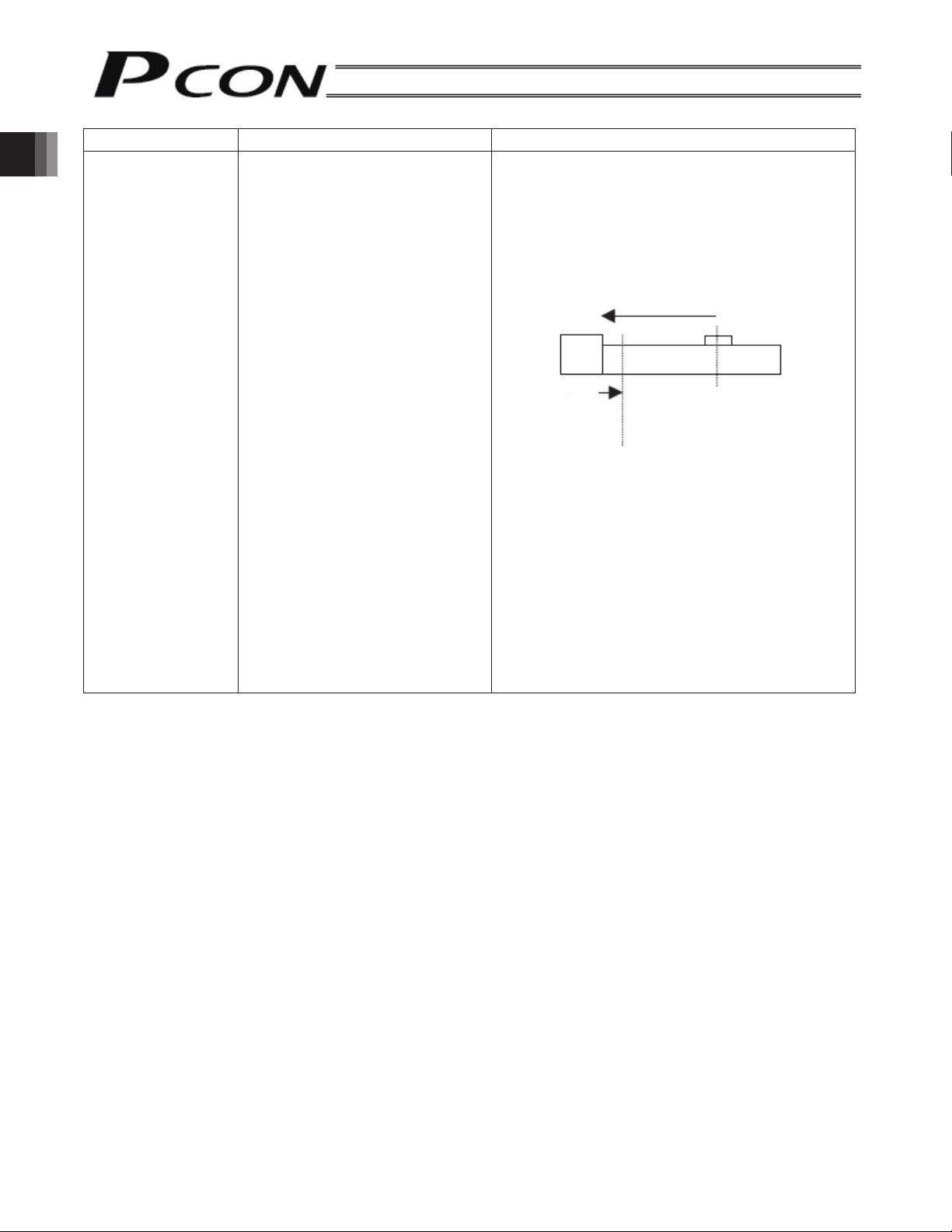
Position check upon
power on
1. Overview
Item Air cylinder PCON-SE
Judgment using a reed switch or
other external detection sensor.
When the power is turned on, mechanical
coordinates are not stored in the controller and thus
the current position is not yet determined.
For this reason, a rear end move command must be
executed after the power has been turned on, in
order to establish coordinates.
The actuator performs homing first, and then moves
to the rear end.
[1]
[2]
Power-on position
Home position
[1] The actuator moves toward the mechanical end
on the motor side at the homing speed.
[2] The actuator contacts the mechanical end,
reverses its direction, and stops temporarily at
the home position.
(Note) Make sure there is no obstacle along the
homing path.
12
Page 25

1.4 Model Number
1. Overview
<Series name>
<Connection with the host>
SE: Serial communication only
<Actuator characteristics>
[Motor flange size]
20P: 20, square
28P: 28, square
28P: 28, square (for RA3 type)
35P: 35, square
42P: 42, square
56P: 56, square
[Encoder type]
I: Incremental
High-acceleration transport
specification
Connection of simple absolute unit
<Power-supply voltage>
0: 24 VDC
<I/O cable length>
0: No cable
* PCON-SE controllers do not come
with an I/O cable.
13
Page 26

1.5 System Configuration
(1) When the gateway unit is used (supporting field network)
1. Overview
Teaching
pendant
PC software
RS232C-compatible
USB-compatible
Optional
Gateway
unit
<RCM-101-MW>
<RCM-101-USB>
DeviceNet/CC-Link/Profibus
SIO communication
PCON-SE controller
Unit 1
RCP2 actuator
Cable length: 5m
Optional
PCON-SE controller
Unit 16
RCP2 actuator
Cable length: 5m
Optional
Input power
supply
24 VDC
Brake release switch to forcibly
release the brake
External EMG switch
Power terminal
block
Caution: (1) If the actuator is not equipped with a brake, it is not required to connect the BK
terminal.
(2) Make the 0V of the gateway unit power supply and PCON-SE power supply in common.
14
Page 27

(2) When the SIO converter is used (RS232C serial communication)
r
r
Connect the teaching pendant, PC or PLC using the SIO converter (RS232C/RS485 conversion) as
shown below.
Teaching pendant
<RCM-T>
Optional
Cable length: 5 m
RS232C-compatible <RCM-101-MW>
USB-compatible <RCM-101-USB>
Supplied
cable
(RCM-101-M
(Female)
PC software
Optional
(Male)
(Female)
RS232C cross cable (commercial product)
(Female)
1. Overview
PCON-SE controlle
SIO converter
Vertical <RCC-TU-SIO-A>
Horizontal <RCC-TU-SIO-B>
e-con
connector
*
* Connect the SIO converter to the
controllers communication line at eithe
TB1 or J4 (J5) on the SIO converter.
RCP2 actuator
Cable length: 5 m
Optional
Caution: Do not connect an equipment to the mini DIN connector and D-sub connector at the same
time.
If an equipment is connected to both connectors at the same time, a communication error
(message level) will generate.
15
Page 28

1.6 Procedure from Unpacking to Trial Run Adjustment
When using this product for the first time, pursue work while paying attention to avoid check omission and
incorrect wiring by referring to the procedure below.
1.
Should there be any incorrect model or insufficient item, contact your dealer.
1. Overview
Controller Actuator Communication cable Motor cable Encoder cable
Operation Manual
<Option>
Teaching pendant PC software
2.
[1] After fixing the actuator, install the robot hand. → Refer to the operation manual on the applicable actuator.
[2] Install the controller. → 3. Installation and Wiring
3.
Wiring of the 24 V power supply
Wiring of the brake release switch to forcibly release the brake (when the actuator is equipped with a brake)
Earth grounding
Wiring of the emergency stop circuit and motor drive power supply
Connection of the motor cable and encoder cable
Connection of communication cable
Check of Packed Items
PCON-SE CB-RCP2-MA*** CB-RCP2-PA***
RCM-T (standard)
RCM-E (simple)
RCM-P (data setting)
Installation
Wiring and Connection
RS232C-compatible <RCM-101-MW>
USB-compatible <RCM-101-USB>
(including provided cables)
Power Supply and Alarm Check
4.
After confirming that the emergency stop circuit is not activated, supply the 24 V power.
The controller is normal if the monitor LED [SV/ALM] on the front panel of the controller illuminates in orange for
the first 2 seconds and then changes to a steady green light.
If the [SV/ALM] illuminates in red, an alarm will be generated.
After connecting the PC or teaching pendant, check the alarm description and remove the cause by referring to “7.
Troubleshooting.”
Check of Servo ON Condition
5.
Confirm that the slider or rod is not contacting the mechanical end.
If the slider or rod is contacting the mechanical end, move it away in the opposite direction.
If the actuator is equipped with a brake, move the slider/rod after turning ON the brake release switch to forcibly
release the brake. At this time, exercise caution not to allow work to drop suddenly due to its own weight. Your
hand may be caught by the dropped work or the robot hand or work itself may be damaged.
It is normal if the actuator achieves servo lock and the monitor LED [SV/ALM] on the front of the controller
illuminates in green.
16
Page 29

Safety Speed Setting
6.
The safety speed has been set to 100 mm/s at the time of shipment.
Change it if necessary. (Limited to 250 mm/s or less) → 5. Parameter Settings
Target Position Setting
7.
Set desired positions in the [Position] field of the position table by using the teaching pendant or PC, or set
numeric values directly.
* If you move the actuator without setting desired positions, the message “No movement data” will be
displayed.
Determine target positions while fine adjusting the transferred work and robot hand.
* Once the target positions have been set, default values are automatically set to the other items (speed,
acceleration/deceleration, positioning band, etc.).
→ 4.1 Description of Position Table
Operational Check of Safety Circuit
8.
Confirm that the drive signal shutdown circuit (or motor drive power shutoff circuit) normally operates.
→ 3. Installation and Wiring
Trial Run Adjustment
9.
Input a movement command from PLC for positioning.
At this time, perform the following fine adjustments if necessary:
If vibration or abnormal sound occurs due to the weight, material or shape of transferred work, reduce the
speed, acceleration or deceleration.
Prevention of interference with peripheral equipment, review of the boundary value of the zone output signal
and positioning band to reduce tact time
Selection of the optimum values for the current-limiting value, evaluation time and push speed during push &
hold operation
→ 4.1 Description of Position Table
1. Overview
17
Page 30

1.7 Warranty
1.7.1 Warranty Period
One of the following periods, whichever is shorter:
18 months after shipment from our factory
12 months after delivery to a specified location
1. Overview
1.7.2 Scope of Warranty
Our products are covered by warranty when all of the following conditions are met. Faulty products covered
by warranty will be replaced or repaired free of charge:
(1) The breakdown or problem in question pertains to our product as delivered by us or our authorized dealer.
(2) The breakdown or problem in question occurred during the warranty period.
(3) The breakdown or problem in question occurred while the product was in use for an appropriate purpose
(4) The breakdown or problem in question was caused by a specification defect or problem, or by the poor
Note that breakdowns due to any of the following reasons are excluded from the scope of warranty:
Note that the warranty only covers our product as delivered and that any secondary loss arising from a
breakdown of our product is excluded from the scope of warranty.
under the conditions and environment of use specified in the operation manual and catalog.
quality of our product.
[1] Anything other than our product
[2] Modification or repair performed by a party other than us (unless we have approved such modification
or repair)
[3] Anything that could not be easily predicted with the level of science and technology available at the time
of shipment from our company
[4] A natural disaster, man-made disaster, incident or accident for which we are not liable
[5] Natural fading of paint or other symptoms of aging
[6] Wear, depletion or other expected result of use
[7] Operation noise, vibration or other subjective sensation not affecting function or maintenance
1.7.3 Honoring the Warranty
As a rule, the product must be brought to us for repair under warranty.
1.7.4 Limited Liability
[1] We shall assume no liability for any special damage, consequential loss or passive loss such as a loss of
expected profit arising from or in connection with our product.
[2] We shall not be liable for any program or control method created by the customer to operate our product
or for the result of such program or control method.
18
Page 31

1.7.5 Conditions of Conformance with Applicable Standards/Regulations, Etc., and Applications
(1) If our product is combined with another product or any system, device, etc., used by the customer, the
customer must first check the applicable standards, regulations and/or rules. The customer is also responsible
for confirming that such combination with our product conforms to the applicable standards, etc. In such a
case we will not be liable for the conformance of our product with the applicable standards, etc.
(2) Our product is for general industrial use. It is not intended or designed for the applications specified below,
which require a high level of safety. Accordingly, as a rule our product cannot be used in these applications.
Contact us if you must use our product for any of these applications:\
[1] Medical equipment pertaining to maintenance or management of human life or health
[2] A mechanism or mechanical equipment intended to move or transport people (such as a vehicle,
railway facility or aviation facility)
[3] Important safety parts of mechanical equipment (such as safety devices)
[4] Equipment used to handle cultural assets, art or other irreplaceable items
(3) Contact us at the earliest opportunity if our product is to be used in any condition or environment that differs
from what is specified in the catalog or operation manual.
1.7.6 Other Items Excluded from Warranty
The price of the product delivered to you does not include expenses associated with programming, the
dispatch of engineers, etc. Accordingly, a separate fee will be charged in the following cases even during the
warranty period:
[1] Guidance for installation/adjustment and witnessing of test operation
[2] Maintenance and inspection
[3] Technical guidance and education on operating/wiring methods, etc.
[4] Technical guidance and education on programming and other items related to programs
1. Overview
18
19
Page 32

2. Specifications
2.1 Basic Specifications
Number of controlled axes 1 axis per unit
Power-supply voltage
Power-supply capacity 2 A max.
Control method Field-weakening vector control (patent pending)
Encoder resolution 800 Pulse/rev
2. Specifications
Positioning command
Backup memory
Positioner operation Maximum 64 points
LED indicator SV (green): Servo ON state, ALM (red): Alarm state
Serial communication RS485 1 channel
Communication protocol Modbus/RTU, Modbus/ASCII
Encoder interface Incremental specification conforming to EIA RS-422A/423A
Forced release of electromagnetic brake 24 V applied to BK terminal on terminal block
Cable length
Dielectric strength
Environment
Protection class Air cooling without blower (IP20)
Weight 128 g or less
External dimensions
Specification item Description
ES-NOCPledoM
24 VDC ± 10%
Position no. specification, numerical specification, simple direct
value/position no. specification
Position table data and parameters are saved in nonvolatile memory.
Serial EEPROM can be rewritten 100,000 times.
Actuator cable: 20 m or less
Communication cable: Total cable length 100 m or less
500 VDC, 10 mΩ
Surrounding air
temperature
Surrounding humidity 85%RH or less (non-condensing)
Surrounding environment Refer to 3.1 Installation Environment
Surrounding storage
temperature
Surrounding storage
humidity
Vibration resistance
0to40°C
-10 to 65°C
90%RH or less (non-condensing)
10 to 57 Hz in XYZ directions, Pulsating amplitude: 0.035 mm
(continuous), 0.075 mm (intermittent)
35 W × 120 H × 68 D mm
20
Page 33
2.2 Name and Function of Each Part of the Controller
Status indicator LEDs
SIO connector
Connector for the teaching
pendant/PC, gateway unit
and SIO converter
The model of the actuator
connected is displayed here.
Motor connector
Connector for the motor cable
SV (green): Indicates the servo ON status.
When this LED is blinking, the
controller is in the auto servo
OFF mode.
ALM (red): Indicates the alarm generated
status or emergency stop
status.
Encoder connector
Connector for the encoder cable
2. Specifications
Power terminal block
Terminal for connecting the brake release switch to forcibly release the brake when the
BK
actuator is used with a brake option.
Connect the opposite side of the switch to 24 V.
A contact for cutting off motor drive power supply with safety category 1 or equivalent
considered.
MPI, MPO
MPI and MPO represent the input side and output side of the motor power supply,
respectively. (Short these terminals using a jumper wire if not used. The controller is shipped
with MPI and MPO shorted.)
24 V Positive side of the 24 VDC input power supply
0V 0V side of the 24 VDC input power supply
Terminal for connecting the emergency stop circuit (motor drive signal shutdown).
EMG−
With the grounding common, connect the opposite side of the emergency stop switch (or
contact) to the negative side of the 24 VDC input power supply.
Notation of the actuator type connected
The type name, ball screw lead length, and stroke of the actuator are indicated. Before connecting cables,
confirm that the actuator is an appropriate one.
Notation example:
RA4C
L: 5mm
ST: 200
Indicates the actuator type is RA4C.
Indicates the ball screw lead length is 5mm.
Indicates the stroke is 200 mm.
21
Page 34

2. Specifications
22
Page 35
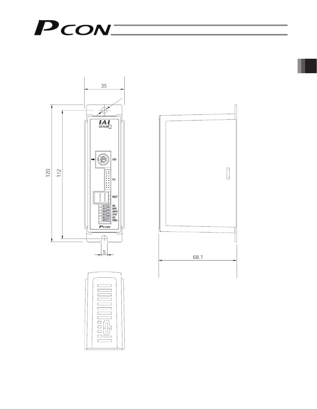
2.3 External Dimensions
An external view and dimensions of the product are shown below.
∅5
2. Specifications
23
Page 36
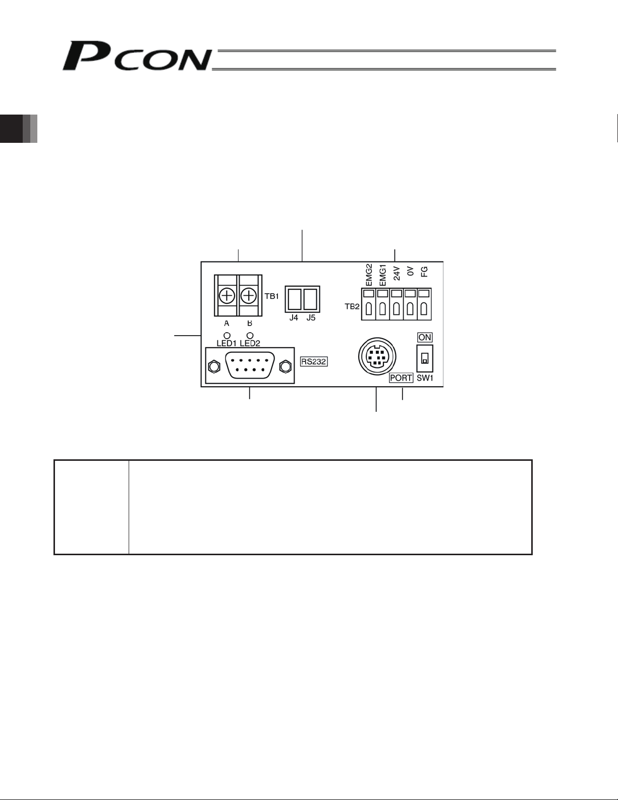
2.4 SIO Converter (Option)
Model: RCB-TU-SIO-A (vertical installation)
RCB-TU-SIO-B (horizontal installation)
This unit is a RS232C-RS485 converter.
If multiple controllers are linked, you can connect a teaching pendant to the mini DIN, 8-pin connector to move, or
edit parameters, for all axes.
● Description of Functions
2. Specifications
[1] Power/emergency stop terminal block (TB2)
EMG1, EMG2 Provide a contact output for the emergency-stop switch on the teaching pendant
24 V Positive side of the 24 V power supply (power supply for the teaching pendant and
0V Negative side of the 24 V power supply
FG FG of the 24 V power supply
[3] Link-connection connector (J4, J5)
[2] Link-connection terminal block (TB1)
[7] Monitor LEDs
[4] D-sub, 9-pin connector
(RCM-T/E). EMG1 and EMG2 connect to the emergency-stop switch on the teaching
pendant when the PORT switch is ON, or are shorted when the PORT switch is OFF.
These terminals comprise an interlock with a safety circuit provided by the user.
conversion circuit, power consumption: 0.1A or less)
[1] Power/emergency stop terminal block (TB2)
[6] PORT switch
[5] Mini DIN, 8-pin connector
[2] Link-connection terminal block (TB1)
A connection port for linking the controller.
“A” on the left side connects to SGA (line color: orange/red 1) of the relay cable.
“B” on the right side connects to SGB (line color: orange/black 1) of the relay cable.
(Note) Be sure to use twisted pair wires for the above two connections (SGA/SGB).
[3] Link-connection connector (J4, J5)
An e-con connection port for linking the controller. The optional link cable (CB-RCB-CTL002) can be
connected to this port directly. However, J4 and J5 allow only two-axis connection. When connecting three or
more axes, use the terminal block of [2].
24
Page 37
[4] D-sub, 9-pin connector (RS232C)
A connection port with the PLC’s communication module. A PC can also be connected to this port. For the
communication cable, use the RS232C cross cable specified below.
[5] Mini DIN, 8-pin connector (RS485)
A connection port with the teaching pendant or PC. For the communication cable, use the cable (with
RS232C/RS485 converter) supplied with the PC software (RCM-101-MW).
[6] PORT switch
A switch for enabling/disabling the mini DIN connector. Set the switch to ON when an equipment is
connected to the mini DIN connector, or OFF when no equipment is connected.
[7] Monitor LEDs
LED1 --- This LED illuminates while the controller is sending data.
LED2 --- This LED illuminates while the RS232 is sending data.
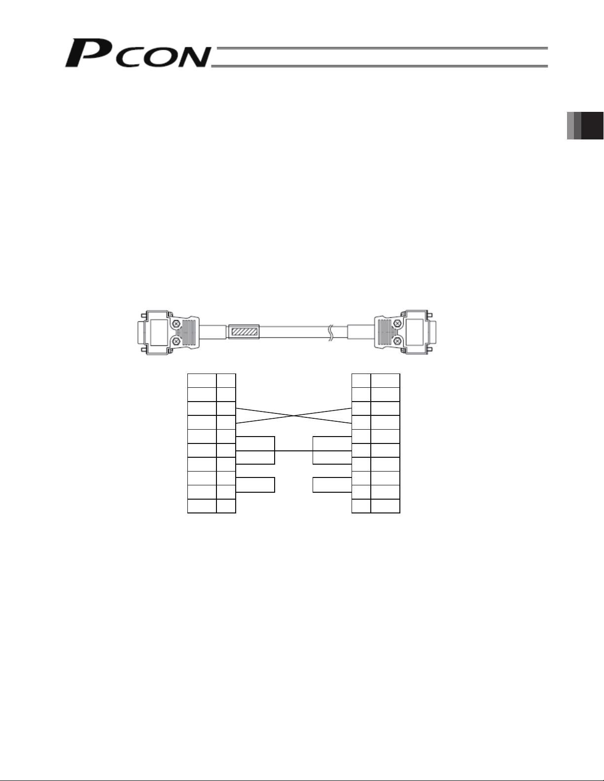
(Reference) Connection diagram of RS232C cross cable (commercial product)
dneCPdneretrevnocOIS
rotcennocnip-9,bus-Drotcennocelamefnip-9,bus-D
No.
Signal No.
1
RD 2
SD 3
DTR 4
SG 5
DSR 6
RS 7
CS 8
9
Signal
1
2
3
4
5
6
7
8
9
(Female if a PC is connected,
or male if a PLC is connected)
RD
SD
DTR
SG
DSR
RS
CS
2. Specifications
25
Page 38

3. Installation and Wiring
3. Installation and Wiring
Pay sufficient attention to the installation environment of the controller.
3.1 Installation Environment
This product is capable for use in the environment of pollution degree 2*1 or equivalent.
*1 Pollution Degree 2 : Environment that may cause non-conductive pollution or transient conductive pollution
by frost (IEC60664-1)
[1] Installation Environment
Do not use this product in the following environment.
• Location where the surrounding air temperature exceeds the range of 0 to 40°C
• Location where condensation occurs due to abrupt temperature changes
• Location where relative humidity exceeds 85%RH
• Location exposed to corrosive gases or combustible gases
• Location exposed to significant amount of dust, salt or iron powder
• Location subject to direct vibration or impact
• Location exposed to direct sunlight
• Location where the product may come in contact with water, oil or chemical droplets
• Environment that blocks the air vent [Refer to 3.3 Noise Elimination and Grounding]
When using the product in any of the locations specified below, provide a sufficient shield.
• Location subject to electrostatic noise
• Location where high electrical or magnetic field is present
• Location with the mains or power lines passing nearby
[2] Storage and Preservation Environment
• Storage and preservation environment follows the installation environment. Especially, when the product is
to be left for a long time, pay special attention to condensed water.
Unless specially specified, moisture absorbency protection is not included in the package when the machine
is delivered. In the case that the machine is to be stored in an environment where dew condensation is
anticipated, take the condensation preventive measures from outside of the entire package, or directly after
opening the package.
3.2 Power Supply
The power supply specification is 24 VDC ± 10%.
(Maximum power capacity: 2 A)
26
Page 39

3.3 Noise Elimination and Grounding
This section explains how to eliminate noise in the use of the controller.
(1) Wiring and power supply
[1] As for grounding, provide a dedicated class D grounding (former class 3 grounding). The grounding cable
shall have a size of 2.0 ~ 5.5 mm
Controller
Use the thickest
possible line and
wire it over the
shortest distance.
2
or larger.
Other
equipment
Controller
Other
equipment
Metal enclosure
Class D grounding
Avoid using this method.
(Former class 3 grounding: Grounding
resistance of 100 Ω or less)
[2] Precautions regarding wiring method
Use a twisted cable for connection to the 24 VDC external power supply.
Separate the controller cables from high-power lines such as a cable connecting to a power circuit. (Do not
bundle together the controller cables with high-power lines or place them in the same cable duct.)
If you wish to extend the motor wiring or encoder wiring beyond the length of each cable supplied with the
controller, consult IAI’s Engineering Service or Sales Engineering Section.
3. Installation and Wiring
(2) Noise sources and elimination
Among the numerous noise sources, solenoid valves, magnet switches and relays are of particular concern when
building a system. Noise from these sources can be eliminated by implementing the measures specified below.
AC solenoid valves, magnet switches and relays
Action --- Install a surge absorber in parallel with the coil.
Point
Install a surge absorber to each coil over a minimum wiring length.
Installing a surge absorber to the terminal block or other part will
be less effective because of a longer distance from the coil.
27
Page 40
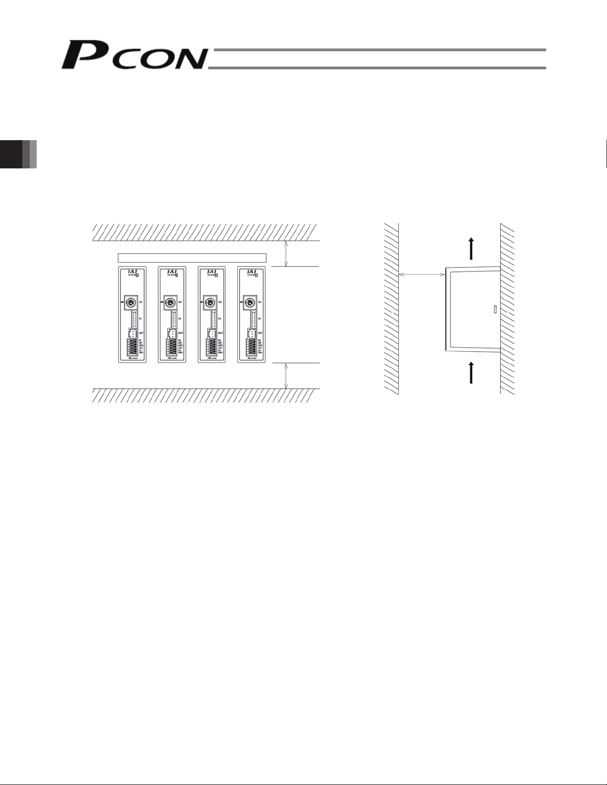
3.4 Heat Radiation and Installation
Design the control panel size, controller layout and cooling method in such a way that the temperature around the
controller will not exceed 40°C.
Install the controller vertically on a wall, as shown below. Since cooling is provided by way of natural convection,
always observe this installation direction and provide a minimum clearance of 50 mm above and below the
controller to ensure sufficient natural airflows.
When installing multiple controllers side by side, providing a ventilation fan or fans above the controllers will help
maintain a uniform temperature around the controllers.
Keep the front panel of the controller away from the wall (enclosure) by at least 80 mm.
3. Installation and Wiring
Fan
50 mm or more
50 mm or more
80 mm or
more
Airflow
Regardless of whether your system consists of a single controller or multiple controllers, provide sufficient
clearance around each controller so that it can be installed/removed easily.
28
Page 41
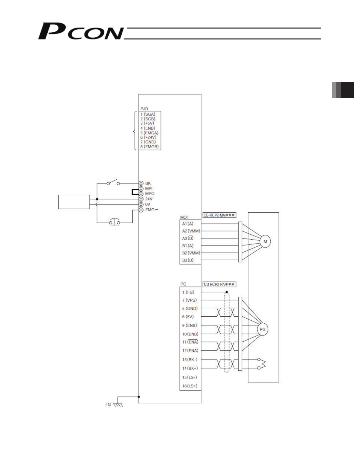
3.5 External Connection Diagram
An example of standard wiring is shown below.
(Note) When encoder relay cables are of the robot cable specification, the line colors will be different, refer
to “3.9.2 Encoder Relay Cables.”
PCON-SE controller
Connected to teaching
pendant/PC, gateway
unit or SIO converter
Brake release
switch to forcibly
Input power supply
24 V DC
release the brake
External EMG
switch
Terminal block
Motor relay cable
Orange
Gray
White
Yellow
Pink
Yellow (Green)
Actuator
Motor
3. Installation and Wiring
Tighten together with the
mounting screw.
Encoder relay cable
Yellow
Blue
Orange
Pink
Purple
Green
Brown
Gray
Red
Encoder
Holding brake
29
Page 42

3.6 Wiring the Power Supply
Connect the +24 V side of the 24 VDC power supply to the 24 V terminal on the power supply terminal block and
the 0V side to the 0V terminal.
Open the cable inlet by pushing
it with a flathead screwdriver.
Input power supply: 24V
24 VDC: 0V
(2 A max. per unit)
Use a power cable satisfying the following specifications:
Power supply
terminal block
Cable inlet
3. Installation and Wiring
Item Description
Applicable wire Twisted wire: AWG size 22 (0.3 mm2) (copper wire)
(Note) Pay attention to terminal treatment to avoid a short
circuit resulting from chips.
If the wire path is long, install a relay terminal block and
change the wire size.
Power supply
terminal block
Isolation sheath temperature
Input power
60°C or more
Relay terminal block
supply
rating
Stripped wire length
3.7 Wiring the Brake Release Switch to Forcibly Release the Brake
If the actuator is equipped with a brake, install the brake release switch for resetting at startup adjustment or in an
emergency.
The switch (24 VDC, contact capacity 0.2 A or more) must be prepared by the customer.
Connect one side of the switch to the positive side of the 24 VDC power supply and the other side to the BK
terminal on the power supply terminal block.
The brake will be released by closing the switch.
Brake release switch to
forcibly release the brake
Power supply
Input power supply:
24 VDC:
(2 A max. per unit)
Danger:
In the case of a vertical axis, release the brake while exercising caution to avoid hands from
being caught and the robot hand or work from being damaged due to a sudden drop.
30
Page 43

3.8 Wiring the Emergency Stop Circuit
y
3.8.1 Drive Signal Shutdown (Standard)
The motor drive is stopped by the controller internal circuit.
The motor drive power supply is not shut off.
(1) When the SIO converter is used
Teaching pendant
EMG push
button
EMG reset
switch
EMG push
button
Terminal block
SIO converter
T.P. connector
Input power suppl
24 VDC
(2 A max. per unit)
SIO connector
SIO
communication
Power supply terminal block
PCON-SE controller
Motor drive
power
supply
Control
power
supply
Connection
detecting
signal (H)
EMG signal
detection
(H)
Time
Drive stop
signal (L)
constant
SIO
connector
connection
detecting
circuit
Motor
drive
circuit
3. Installation and Wiring
Power supply terminal block (Unit 2)
Power supply terminal block (Unit 3)
Caution: The input current to the EMG terminal of PCON-SE is 5 mA. When connecting the contact of
the EMG relay R to the EMG terminals of multiple controllers, check the current capacity of
the relay contact.
31
Page 44

(2) When the gateway unit is used
r
(
)
g
)
3. Installation and Wiring
Teachingpendant
EMG push
button
EMG reset
switch
power supply
EMG push
button
Gateway
Gateway unit
T.P. connecto
Port switch
Input power supply
24 VDC
2 A max. per unit
SIO connector
SIO
communication
Power supply terminal block
PCON-SE controller
EMG signal
detection (H)
Motor drive
power
supply
Control
power
supply
Connection
detecting
signal (H)
Time
constant
SIO
connector
connection
detecting
circuit
Drive stop
si
nal (L
Motor
drive
circuit
Power supply terminal block (Unit 2)
Power supply terminal block (Unit 3)
Caution: (1) The input current to the EMG terminal of PCON-SE is 5 mA. When connecting the
contact of the EMG relay R to the EMG terminals of multiple controllers, check the
current capacity of the relay contact.
(2) Make the 0V of the gateway unit power supply and PCON-SE power supply in
common.
32
Page 45

3.8.2 Cutting off the Motor Drive Power Supply
(
)
circu
If the safety category of the entire equipment requires motor drive power cut off, connect the EMG relay contact
between the MPI terminal and MPO terminal.
In addition, connect 24 V of the controller power supply to the EMG terminal.
(Note) Please pay sufficient attention that the EMG switch of the teaching pendant leads to motor drive
signal shutdown and not motor drive power cutoff.
(1) When the SIO converter is used
Teaching pendant
EMG reset
switch
EMG push
button
EMG push
button
Terminal block
SIO converter
T.P. connector
Input power supply
24 VDC
2 A max.perunit
SIO connector
SIO
communication
Power supply terminal block
PCON-SE controller
Connection
detecting
signal (H)
EMG signal
detection
(H)
Time
constant
Drive stop
signal (L)
Motor drive
power
supply
Control
power
supply
SIO
connector
connection
detecting
it
Motor
drive
3. Installation and Wiring
Power supply terminal block (Unit 2)
Power supply terminal block (Unit 3)
33
Page 46

(2) When the gateway unit is used
3. Installation and Wiring
Teaching pendant
EMG push
button
EMG reset
switch
EMG push
power supply
button
Gateway
Gateway unit
T.P. connector
Port switch
Input power supply
24 VDC
(2 A max. per unit)
SIO connector
SIO
communication
Power supply terminal block
PCON-SE controller
Connection
EMG signal
detection
Motor drive
power
supply
Control
power
supply
detecting
signal (H)
(H)
Time
Drive stop
signal (L)
constant
SIO
connector
connection
detecting
circuit
Motor
drive
circuit
Power supply terminal block (Unit 2)
Power supply terminal block (Unit 3)
Caution: [1] The input current to the EMG terminal of PCON-SE is 5 mA. When connecting the
contact of the EMG relay R to the EMG terminals of multiple controllers, check the
current capacity of the relay contact.
[2] Make the 0V of the gateway unit power supply and PCON-SE power supply in
common.
34
Page 47

3.9 Connecting the Actuator
3.9.1 Motor Relay Cable
• Connect the motor relay cable to the MOT connector.
Signal table for controller-end connector (CN2)
Pin No. Signal Wire color Description
A1 A Orange Motor drive line (phase A-)
A2 VMM Gray
A3
B
White
B1 A Yellow
B2 VMM Pink
B3 B
Yellow (Green)
Motor power line
Motor drive line (phase B-)
Motor drive line (phase A+)
Motor power line
Motor drive line (phase B+)
3. Installation and Wiring
Controller end
Pin arrangements of CN2
Cable color
Orange
Gray
White
Yellow
Pink
Yellow (Green)
Housing: 1-1318119-3 (AMP)
Receptacle contact: 1318107-1
Signal name
Pin No.
Actuator end
Pin arrangements of CN1
Pin No.
Housing: SLP-06V (JST)
Socket contact: BSF-21T-P1.4
Signal name
Cable color
Yellow
Gray
Orange
Yellow (Green)
Pink
White
35
Page 48
3. Installation and Wiring
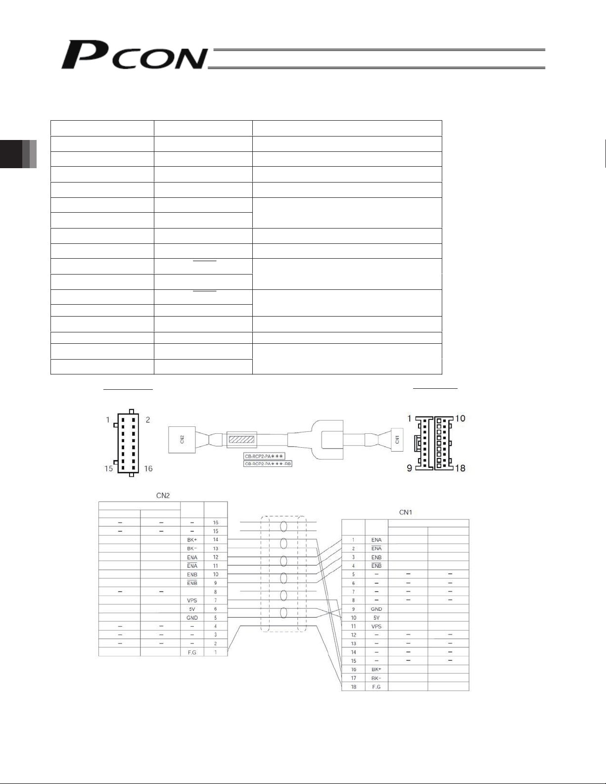
3.9.2 Encoder Relay Cable
• Connect the encoder relay cable to the PG connector
Signal table for controller-end connector (CN2)
Pin No. Signal name Description
1 F.G Shield wire
2 - (Not used)
3 - (Not used)
4 - (Not used)
5 GND
6 5V
7 VPS Encoder control signal output
8 - (Reserved)
9 ENB
10 ENB
11 ENA
12 ENA
13 BK- Brake power14 BK+ Brake power+
15 -
16 -
Encoder power output
Encoder differential signal phase B input
Encoder differential signal phase A input
(Not used)
Controller end
Pin arrangements of CN2
Standard cable
Robot cable
Cable color
Standard cable
Purple
White
(paired with purple)
Blue
White
(paired with blue)
Yellow
White
(paired with yellow)
Green
Red
White
(paired with red)
Ground
Robot cable
Brown
Green
Purple
Yellow
Orange
Ground
Red
Gray
Pink
Blue
Signal
name
(Reserved)
Housing: PHDR-16VS (JST)
Contact: SPHD-001T-P0.5
*** indicates the cable length (L) (up to 20 m).
Example) 080 = 8 m
Pin
Pin
Housing: XMP-18VS (JST)
Contact: BXA-001T-P0.6
Retainer: XMS-09V
Signal
name
Actuator end
Pin arrangements of CN1
Cable color
Pink
Blue
Red
Robot cable
(paired with blue)
(paired with yellow)
(paired with red)
(paired with purple)
Standard cable
Brown
Green
Purple
Orange
Yellow
Gray
Ground
Blue
White
Yellow
White
White
Red
Green
Purple
White
Ground
36
Page 49
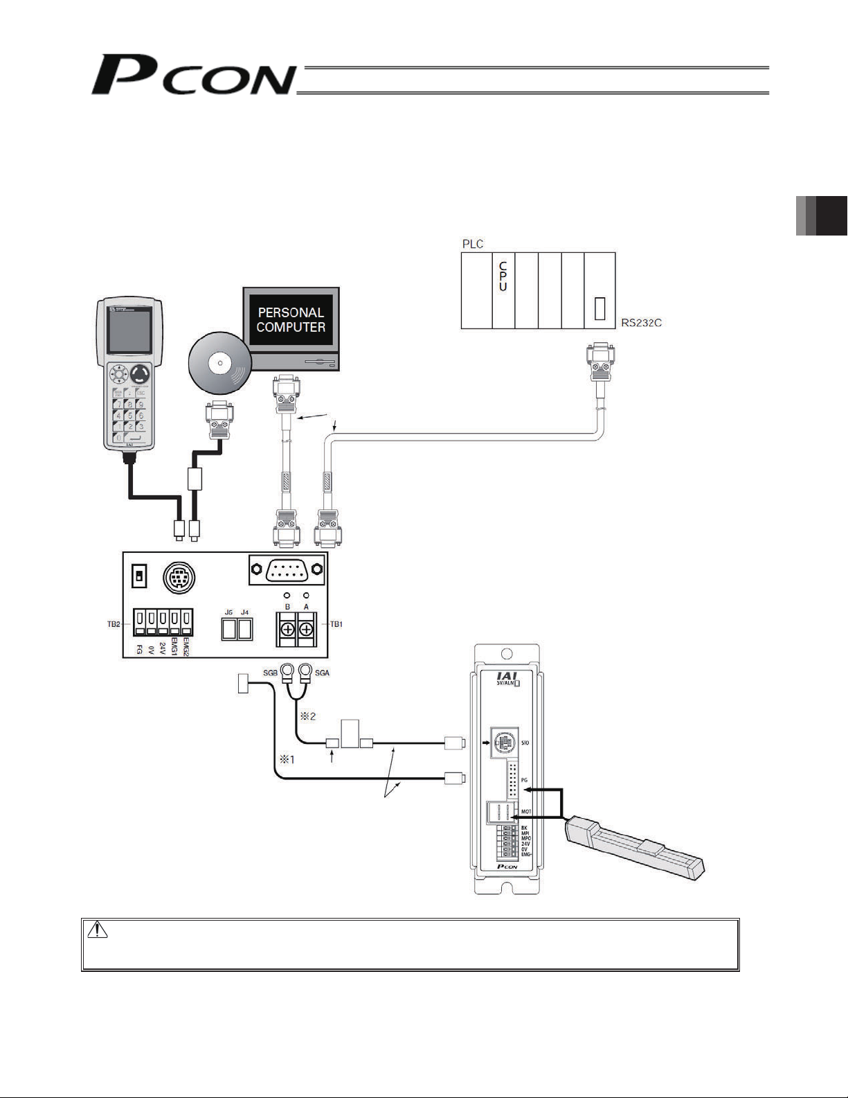
3.10 Connecting the SIO Communication
3.10.1 Connecting the RS232C Serial Communication
(1) Basic information
Connect the teaching pendant, PC or PLC, and controller using the SIO converter (RS232C/RS485 conversion)
as shown below.
Teaching pendant
<RCM-T>
Optional
Cable length: 5 m
RS232C-compatible <RCM-101-MW>
USB-compatible <RCM-101-USB>
PC software
Optional
(Male)
(Female)
RS232C cross cable (commercial product)
3. Installation and Wiring
Supplied cable
(RCM-101-MW)
SIO converter
Vertical <RCC-TU-SIO-A>
Horizontal <RCC-TU-SIO-B>
(Female) (Female)
(Male)
e-con
connector
Four-way junction
Controller link cable
(CB-RCB-CTL002)
*1: To connect a communication line
between the SIO converter and
controller, use TB1 or J4 (J5) of the
SIO converter as shown below.
*2: Produce this line by using the
accessory of the controller link cable.
PCON-SE controller
RCP2 actuator
Cable length: 5m
Optional
Caution: Do not connect an equipment to the mini DIN connector and D-sub connector at the same
time. If the both are connected at the same time, a communication error (message level) will
occur. Make the 0V of the SIO converter and controller in common.
37
Page 50

(2) Connecting the multiple axes
Item Description
Maximum number of units that can
be connected
Communication cable length Total cable length: 100 m or less
SIO communication main line Twisted-pair shielded cable (AWG22)
Terminal resistor
Teaching pendant PC, PLC
16 axes max. (depending on the operation mode)
Recommended brand: Taiyo Electric Wire & Cable HK-SB/20276 x L, 2P x
AWG22
220 Ω, 1/4 W
E-Con connector (AMP 4-1473562-4: housing color green)
E-Con connector (AMP 3-1473562-4: housing color orange)
Junction (AMP 5-1473574-4)
3. Installation and Wiring
Recommended: HK-SB/20276 x L, 2P x AWG22
SIO converter
SIO communication main line*
Terminal resistor
Controller link cable
Controller 1
Controller 2 Controller n
* The SIO communication main line must be prepared by the customer.
Each one unit of the junction, E-Con connector and terminal resistor are supplied with the controller link
cable.
Caution: [Note 1] If normal communication cannot be performed with a communication error occurring when
the total communication cable length is 10 m or more, connect the terminal resistor to the
last axis.
[Note 2] For the power supplies of the SIO converter and all controllers, make 0V in common.
When using the +24 V pin as the grounding point (+ common), confirm that the GND pin is
not connected to ground.
Exercise caution particularly when connecting a PC. If the RS232C communication cable
is connected directly, the +24-V power supply may be shorted because the GND and FG
pins are connected inside the PC.
[Note 3] Connect a shielded cable to FG on an axis basis.
[Note 4] If the total link cable length is more than 30 m, use the wire size of 22AWG or larger.
38
Page 51
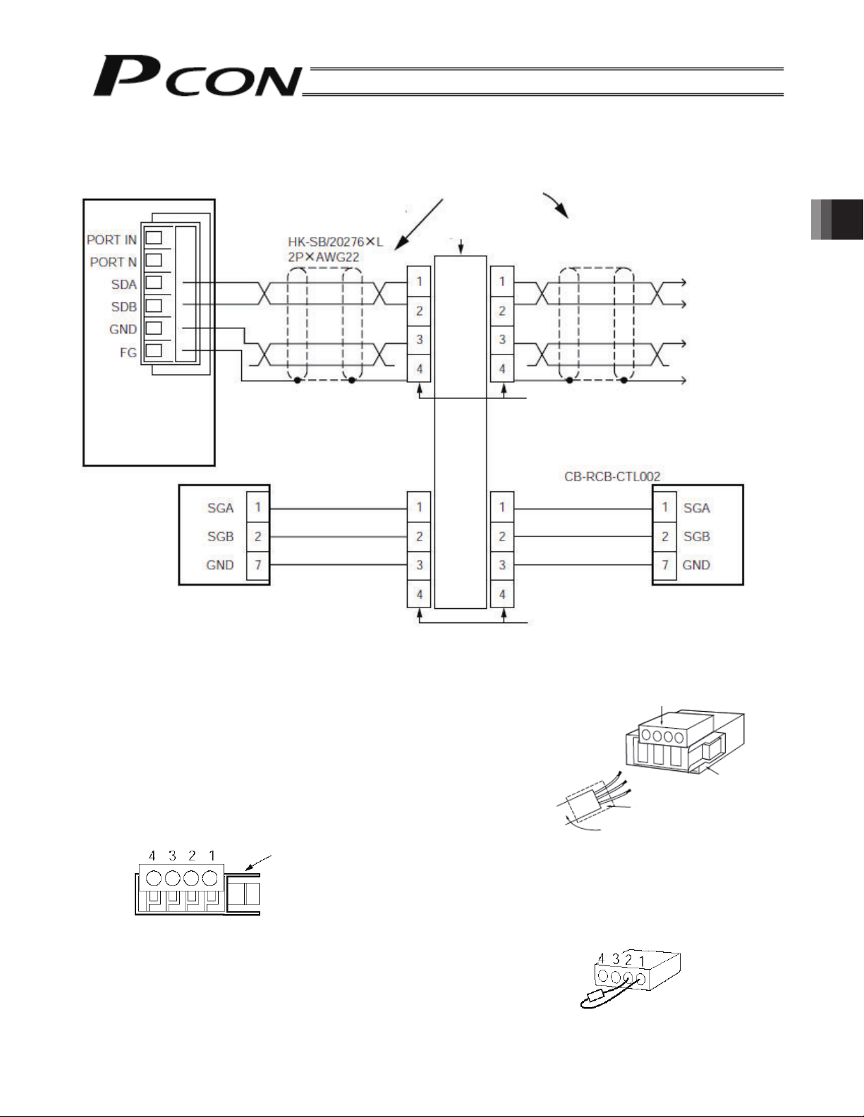
Detailed Connection Diagram
Connection details of SIO communication are shown below. The controller link cable is available as an option,
but the communication trunk line must be prepared by the customer.
Gateway Unit
Paired shielded cable
Recommended: Taiyo
Cabletec
Yellow
Orange
Blue
SIO communication
4-way junction (AMP: 5-1473574-4)
e-CON connector (AMP: 4-1473562-4)
Controller link cable
Yellow
Orange
Blue
Axis 1
Housing color: Green
3. Installation and Wiring
1st unit 2nd unit
e-CON connector (AMP: 3-1473562-4)
Housing color: Orange
Preparation of Communication Main Line
e-CON connector
[1] Strip the sheath of a double shielded twisted-pair cable by
approx. 15 to 20 mm.
Apply pressure.
[2] Place a cable protection tube over the cable.
[3] Insert the three wires into the cable insertion holes in the
connector without stripping the core sheath.
[4] With the cable inserted in the press-fit cable housing, apply
pressure from above to pressure-weld the core wires.
[5] Heat-treat the cable protection tube.
e-CON connector pin numbers
Locking tab
Cable tube
Double shielded twisted-pair
shielded
Be sure to insert a terminal resistor (220 Ω, 1/4 W) at the terminal end of the communication trunk line
(between pins 1 and 2 of the e-CON connector)
Locking tab
39
Page 52
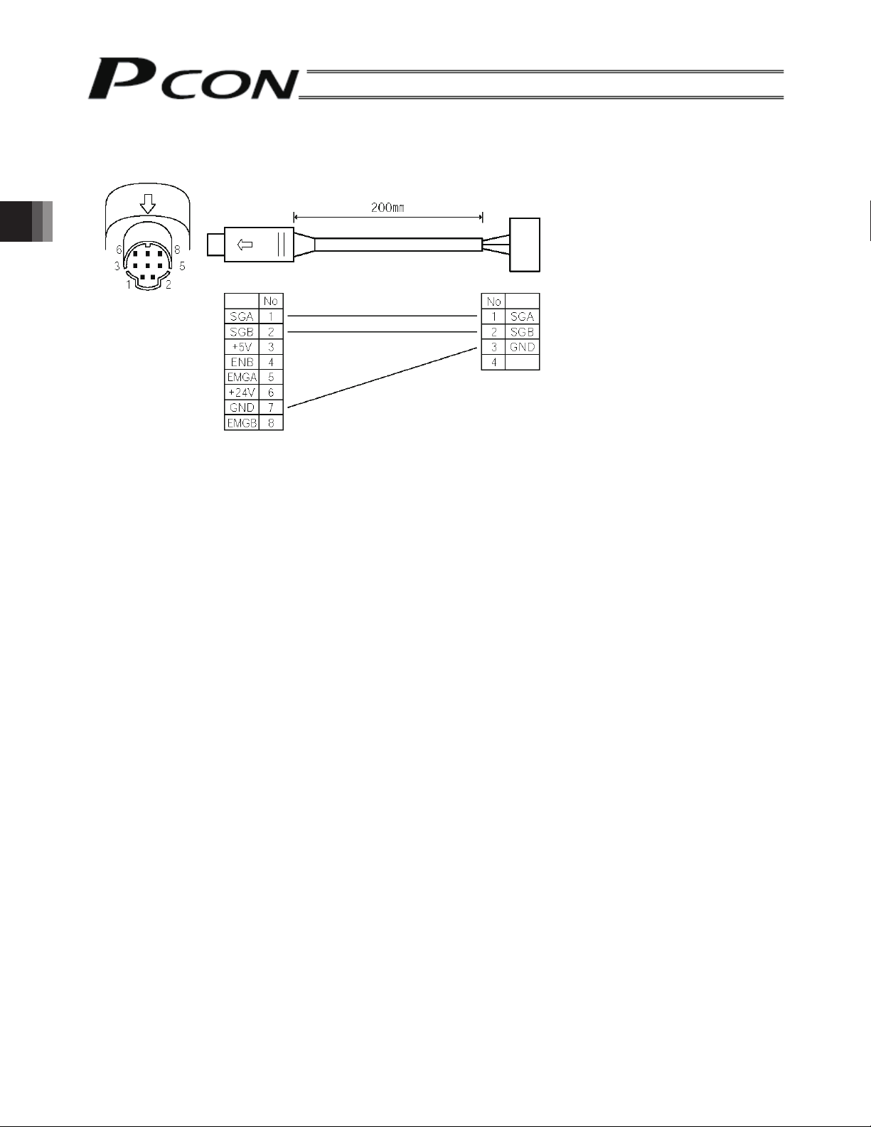
3. Installation and Wiring
Controller link cable (CB-RCB-CTL002)
*This cable is available as an option for each controller.
Controller end
e-CON connector
3-1473562-4
(Housing color: Orange)
Mini DIN connector
Signal
Yellow
Signal
Orange
Blue
The following parts are supplied with the controller link cable.
[1] 4-way junction Model: 5-1473574-4 by AMP x 1 unit
[2] e-CON connector 4-1473562-4 by AMP x 1 unit
Outer diameter of applicable wire 1.35 to 1.6 mm
[3] Terminal resistor
220 Ω 1/4 W With e-CON connector x 1 unit
40
Page 53

3.11 Connection to Field Network
The gateway unit is used to connect the controllers to the field network of DeviceNet, CC-Link, or Profibus. The
connection to the gateway unit is shown below.
The details are the same as those in 3.10.1 (2).
Field network
E-Con connector (AMP 4-1473562-4: housing color green)
SIO communication
main line
Gateway unit
(built-in terminal resistor)
PCON-SE
controller
E-Con connector (AMP 3-1473562-4: housing color orange)
Junction (AMP 5-1473574-4)
Recommended: HK-SB/20276 x L, 2P x AWG22
Terminal resistor
R=220 Ω
1/4 W
3. Installation and Wiring
Controller link cable
CB-RCB-CTL002
Axis 1 Axis 2 Axis n
3.12 Assignment of Axis Number
If multiple controller axes are connected by means of RS232C serial communication or field network connection,
an axis number must be assigned to each controller.
Connect a teaching pendant or PC (software) to the SIO connector of a desired controller based on 1:1
relationship. Overviews of operations using a teaching pendant and PC software are provided below.
Overview of operation using a PC
[1] Open the main screen → [2] Click Setting (S) → [3] Bring the cursor to Controller Setting (C)
→ [4] Bring the cursor to and click Assign Axis Number (N) → [5] Enter a desired number in the axis number
table.
Overview of operation using a teaching pendant RCM-T
[1] Open the User Adjustment screen → [2] Use the T key to bring the cursor to Assigned No. _
→ [3] Enter a desired axis number and press the return key → [4] Enter “2” in Adjustment No. _ and press the
return key.
Overview of operation using a teaching pendant RCM-E
[1] Open the User Adjustment screen → [2] Press the return key to open the Assigned No. _ screen
→ [3] Enter a desired axis number and press the return key → [4] Enter “2” in Adjustment No. _ and press the
return key.
For the details of specific operating procedures, refer to each operation manual.
41
Page 54

3.13 Setting the Baud Rate
When inter-connecting multiple controllers, baud rates of all controllers must be set to the same value.
The baud rate can be set using parameter No. 16.
Connect a teaching pendant or PC (software) on a 1-to-1 relationship to the SIO connector whose baud rate you
wish to set, and set a desired baud rate.
4. Description of Operating Functions
The PCON-SE is a dedicated serial communication controller supporting 64 positions (positioning points). This
controller does not support PIO patterns.
With PCON-SE controllers, the actuator can be operated in two ways: [1] “Operation by position number
specification” where a position number is specified, and [2] “Operation by numeric specification” where values
relating to a desired operation are specified directly.
To move the actuator to a specified position in the “operation by position number specification,” it is basically
required to create a position table in advance and enter a target position in the “Position” field. For the target
position, there are the absolute coordinate specification (Absolute) to enter a distance from the home position and
the relative coordinate specification (Incremental) to enter a relative movement distance from the current position.
When the target position is entered, the default value set with a parameter is automatically registered in the other
field.
The default value varies depending on the actuator characteristics.
The PCON-SE can be operated in a field network environment or RS232C serial communication environment.
Accordingly, also read the operation manual for your gateway unit and serial communication operation manual for
your ROBO Cylinder series.
4. Description of Operating Functions
The key functions available in operation by position number specification and operation by numeric specification
are summarized on the following page.
If the actuator is operated in the command specification mode via a gateway unit, the PIO pattern of any
positioner operation axis (set by gateway control signals PPS0 to PPS2) becomes “0.”
42
Page 55

Command specification
mode
×:noitarepotceridelpmiS×××
Specify the position
table no.
Set it in the position
table.
Set it in the position
table.
Set the acceleration
and deceleration
separately in the
Specify the position
data directly.
position table.
Set it in the position
table.
Set it in the position
table.
Combine two or more
position nos.
Positioner operation:
: Direct control : Indirect control ×: Invalid
yawetagkniL-CCyawetagteNeciveD
Position data limiting mode Normal positioning mode Push & hold enabledm ode
mode
Command specification
Direct numeric
specification mode
Spec ify a nu meri c
value directly.
Spec ify a nu meri c
value as the
acceleration/
deceleration.
The acceleration/
deceleration data is
accepted at
positioning start time.
Therefore, to specify
the deceleration
different from the
acceleration, change
the acceleration/
deceleration data
during movement and
restart the controller.
cannot be performed.
Issue a position
Specify the position
data directly.
Spec ify a nu meri c
Specify the position
Specify the position
Specify the position
Specify the position
value directly.
data directly.
data directly.
data directly.
data directly.
Spec ify a nu meri c
value as the
acceleration/
deceleration.
The acceleration/
deceleration data is
accepted at
positioning start time.
Therefore, to specify
the deceleration
different from the
acceleration, change
the acceleration/
deceleration data
during movement and
Set the parameter as
the acceleration/
deceleration.
setting is performed as
the acceleration/
deceleration, the
acceleration and
deceleration cannot be
Set the parameter.
Specify the position
table no.
Set it in the position
table.
Spec ify a nu meri c
value directly.
× Since parameter
Set the acceleration
and deceleration
separately in the
position table.
Set the acceleration
and deceleration
The acceleration/
Spec ify a nu meri c
deceleration data is
value as the
acceleration/
deceleration.
set separately.
separately in the
position table.
accepted at
positioning start time.
Therefore, to specify
the deceleration
during movement and
different from the
acceleration, change
the acceleration/
deceleration data
command by adding
× Direct processing
restart the controller.
cannot be performed.
Issue a position
command by adding
× Direct processing
cannot be performed.
Issue a position
command by adding
× Direct processing
Set it in the position
table.
cannot be performed.
Issue a position
command by adding
restart the controller.
×Directprocessing
Direct numeric
thesamedistanceto
thesamedistanceto
the same distance to
thesamedistanceto
specification
or subtracting it from
the current position
with the host PLC.
Direct processing
cannot be performed.
Issue a position
command by adding
thesamedistanceto
or subtracting it from
the current position
with the host PLC.
or subtracting it from
the current position
with the host PLC.
or subtracting it from
the current position
with the host PLC.
or subtracting it from
the current position
with the host PLC.
cannot be performed.
Issue a position
command by adding
thesamedistanceto
or subtracting it from
the current position
××
× Direct proces sing
Set it in the position
table.
Combine two or more
position nos.
accepted at
positioning start time.
value directly.
The speed data is
with the host PLC.
×:noitarepotceridelpmiS×
Positioner operation:
speed data during
movementand restart
Therefore, to change
the controller.
the speed during
movement, change the
4. Description of Operating Functions
Serial communication
specification mode
Gateway position number
Operation by position number specif ication Operation by numeric specification
Serial communication
List of PCON-SE Functions
value as the
acceleration/
data directly.
Spec ify a nu meri c
Same as at the left Specif y the position
Same as at the left
Specify the position
table no.
Set it in the position
Positioning operation
Home return operation
Speed setting
deceleration.
value directly.
table.
The acceleration/
deceleration data is
accepted at positioning
start time. Therefore,
to specify the
deceleration different
from the acceleration,
change the
acceleration/
Same as at the left
Same as at the left Specif y a num eric
Set the acceleration
and deceleration
separately in the
position table.
Set the acceleration
and deceleration
separately in the
position table.
Acceleration/deceleration
setting
Operation at different
acceleration/deceleration
control flag is set to “1,”
incremental operation
deceleration data
during movement and
starts.
restart the controller.
Same as at the left If bit 2 of the CTLF
table.
Pitch (incremental) feeding Set it in the position
accepted at positioning
Same as at the left Spec ify a nu meri c
Same as at the left The speed data is
Combine two or more
position nos.
Set it in the position
table.
Speed change during
movement
Push & hold operation
start time. Therefore,
during movement and
Set it with the user
parameter.
Output signal: ZONE1,
ZONE2
Set it with the user
parameter. Output
signal: ZONE1,
ZONE2
Same as at the left Same as at the left Same as at the left Same as at the left Same as at the left Same as at the left Same as at the left Same as at the left
table or with the user
parameter. Output
signal: PZONE,
ZONE1, ZONE2
Set it in the position
Zone signal
Pause
Power saving mode
The power-saving mode
for full-servo control can be
selected using parameter
53. (The auto servo OFF
mode cannot be selected.)
Position table Required Required Not required Not required Required Not required Required Required Required
restart the controller.
to change the speed
during movement,
change the speed data
43
Page 56
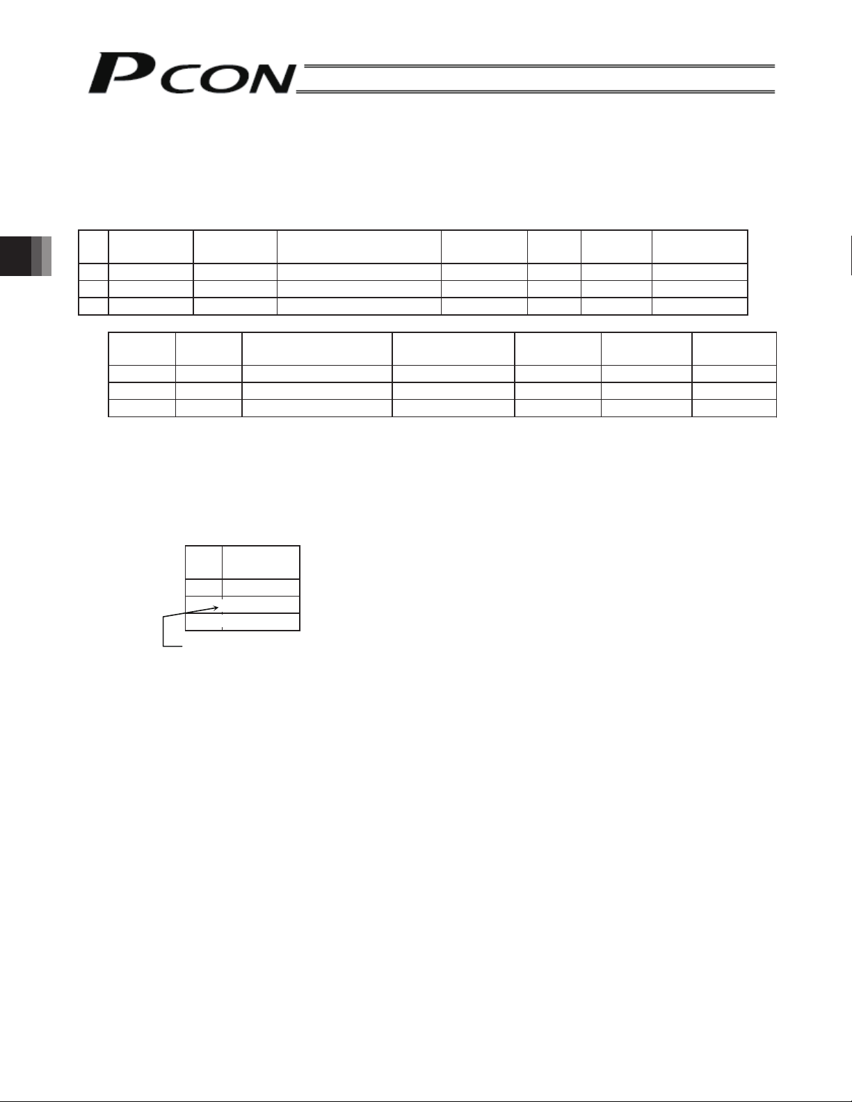
4.1 Description of Position Table
A
A position table is created by using the PC software or teaching pendant.
For its usage, refer to each operation manual.
In this section, a position table is explained by taking the PC software screens as examples.
(In the case of the teaching pendant, the display contents are different.)
No.
(1) No.: Indicate the position data number.
(2) Position: Enter the target position to move the actuator to, in [mm].
4. Description of Operating Functions
Position
[mm]
0 5.00 300.00 0.30 0.30 0 0 0.10
1 380.00 300.00 0.30 0.10 0 0 0.10
2 200.00 300.00 0.30 0.10 0 0 0.10
Zone +
[mm]
100.00 0.00 0 0 0 4
400.00 300.00 0 0 0 0
250.00 150.00 0 0 0 0
Absolute coordinate specification: Enter the distance to the target actuator position from the home.
Relative coordinate specification: Under the assumption of a constant pitch, a relative amount from the
current position is indicated.
Speed
[mm/s]
Zone –
[mm]
No.
0 5.00 Absolute coordinate specification: 5 mm from the home
1 10.00 Relative coordinate specification: +10 mm from the current position
2 -10.00 Relative coordinate specification: -10 mm from the current position
Acceleration mode Incremental
Position
[mm]
=
=
cceleration/deceleration
[G]
Deceleration
[G]
Push
[%]
Command
mode
Threshold
[%]
Stop mode Comment
Positioning
band [mm]
* Indicates the relative coordinate specification with the teaching pendant (RCM-T).
(3) Speed: Enter the speed at which the actuator will be moved, in [mm/sec].
The default value varies depending on the actuator type.
44
Page 57

(4) Acceleration/deceleration: Enter the acceleration/deceleration at which the actuator will be moved, in [G].
Basically, use acceleration/deceleration within the catalog rated value range.
The input range allows larger value input than the catalog rated values, on the assumption that the tact time
will be reduced if the transfer mass is significantly smaller than the rated value.
Make the numeric value smaller if transfer work vibrates and causes trouble during
acceleration/deceleration.
Speed
Acceleration Deceleration
Time
Start position Target position
The acceleration will become sudden if the numeric value is made larger, and it will become gradual if the
numeric value is made smaller.
Caution: Enter appropriate values for the speed and acceleration/deceleration in such a way as to
prevent excessive impact or vibration from being applied to the actuator in consideration of
the installation conditions and the shape of transferred work by referring to the “List of
Actuator Specifications” in the Appendix.
Increasing such values largely relates to the transfer mass and the actuator characteristics
vary depending on the model, consult IAI regarding the input-limiting values.
(5) Push: Select the positioning operation or push & hold operation.
The default value is “0.”
0: Normal positioning operation
Other than 0: Indicates the current-limiting value and indicates the push & hold operation.
(6) Threshold: This field is invalid in the case of this controller.
The default value is “0.”
(7) Positioning band: The “positioning operation” and “push & hold operation” have different implications.
4. Description of Operating Functions
Positioning operation
It defines the distance to the target position from a
position at which the position complete signal turns
ON.
Since increasing the positioning band value hastens
the next sequence operation, it becomes a factor for
tact time reduction. Set the optimum value by
considering a balance of the entire equipment.
Timing of position complete
signal turning ON
Positioning band
Target position
45
Page 58

Push & hold operation
It defines the maximum push amount from the target position in the push & hold operation.
Set the positioning band in such a way as to prevent positioning completion before the actuator contacts
work by considering mechanical variations of work.
Position at which the position complete signal turns ON when the actuator
Speed
Target position
contacts work and push completion is judged
Push
speed
Positioning band (maximum push amount)
(8) Zone +/-:It defines the zone where the zone output signal turns ON.
For added flexibility, these parameters can be set separately for each target position.
[Setting example]
No.
Position
[mm]
Zone +
[mm]
Zone –
[mm]
Comment
0 5.00 100.00 0.00
1 380.00 400.00 300.00
2 200.00 250.00 150.00
4. Description of Operating Functions
Movement command to position No. 0
Zone output signalZone output signal
Movement command to position No. 1
Zone output signal
Home Target position + side limit
− side limit
+ side limit
46
Page 59

(9) Acceleration/deceleration mode: This field is not available for this controller.
The default value is 0.
(10) Incremental: It defines whether the specification is the absolute coordinate specification or relative
coordinate specification.
The default value is 0.
0: Absolute coordinate specification
1: Relative coordinate specification
(11) Command mode: This field is invalid in this controller.
The default value is 0.
(12) Stop mode: This field is invalid in this controller.
The default value is 0.
Use parameter No. 53 to set the power-saving mode you wish to apply while the actuator is
waiting.
The full-servo control mode can be selected by setting “4” in the parameter.
Full-servo Control Mode
You can lower the holding current (standstill current after completion of positioning) of a pulse motor by
servo-controlling the motor.
Although how much the current comes down varies depending on the actuator mode, load condition, etc.,
normally the holding current normally drops to approximately one-half to one-quarter.
Since the servo remains ON, position deviation will not occur.
You can check the actual holding current on the current monitor screen of the PC software.
To enable this mode, set “4” in the parameter.
4. Description of Operating Functions
47
Page 60

4.2 Setting Data in Numeric Specification Mode
If operation is performed in the numeric specification mode, the position table will become invalid. Set the data
related to operation (target position, speed, acceleration/deceleration, current-limiting value during push & hold
operation, positioning band, etc.) directly via serial communication.
For details, refer to the Gateway Unit Operation Manual and ROBO Cylinder Series Serial Communication
Operation Manual.
4. Description of Operating Functions
48
Page 61

4.3 Control Signals, Control Data
In order to operate PCON-SE via serial communication, it is required to write/read the 16-bit internal memory
(Modbus register, Modbus status) of the controller. The main signals and their symbol names handled at that time
are shown below.
For details, refer to the serial communication operation manual for your ROBO Cylinder series.
(1) Controller Input Signals
(PLC → Controller)
Register
Device
control
register
DRG1
Address
0D00H
[Common]
*1
Bit
address
15
0401H 14 SFTY
13
0403H 12 SON
11 – 9
0407H 8 RES
7
6
040AH 5 STP
040BH 4 HOME
040CH 3 CSTR
Bit
position
2 − 0
Signal
symbol
⎯⎯
Safety speed command Safety speed set with the parameter
⎯⎯
Servo ON command 0: Servo OFF, 1: Servo ON
⎯⎯ ⎯
Alarm reset
⎯⎯ ⎯
⎯⎯ ⎯
Pause command 0: Normal, 1: Pause (deceleration stop)
Home return command
Positioning start
⎯⎯ ⎯
Signal name Description
⎯
0: Invalid, 1: Valid
⎯
0: Normal, “0” → “1” rise edge: Alarm reset
“0” → “1” rise edge: Home return operation
0: Normal, “0” → “1” rise edge: Positioning start
to the target position specified with the position
no.
4. Description of Operating Functions
*1 The meanings of [Common], [POS specification] and [Numeric specification] are as follows:
[Common]: Used in common in both operation by position number specification and operation by
numeric specification.
[POS specification]: Used in the operation by position number specification
Numeric specification]: Used in the operation by the numeric specification
49
Page 62

(PLC → Controller)
Register
Bit
address
Bit
position
Position no.
specification
15 – 6
register
POSR
Address
0D03H
*1
[POS
specification]
043AH 5 PC32
043BH 4 PC16
043CH 3 PC8
043DH 2 PC4
043EH 1 PC2
043FH 0 PC1
Position no.
specification
⎯
15 – 6
register
POSR
Address
9800H
*1
[POS
4. Description of Operating Functions
specification]
⎯
⎯
⎯
⎯
⎯
⎯
5 PC32
4 PC16
3 PC8
2 PC4
1 PC2
0 PC1
Signal
symbol
Signal name Description
⎯⎯ ⎯
⎯
Specify the command position no. with the 6-bit binary
code.
⎯
⎯
Setting the position start signal CSTR to “1” starts
positioning operation.
⎯
⎯
⎯
⎯⎯ ⎯
⎯
The same description as the above. However, if the
position number is specified in this register, positioning
⎯
⎯
operation starts at the same time as writing.
It is not required to set the start signal CSTR to “1.”
⎯
⎯
⎯
50
Page 63

(PLC → Controller)
Register Address Description
PCMD
Position data
9900H
specification
9901H
*1
[Numeric
specification]
INP
Position data
9902H
specification
9903H
*1
[Numeric
specification]
VCMD
Speed
9904H
specification
b15 b8 b7 b0
High
Sign
order
Low
order
32-bit signed integer (unit: 0.01 mm)
The setting range is FFF0BBC1H to 000F423FH (-999999 to 999999).
• If a negative value is set, it is displayed as a 2’s complement. Accordingly, the
most significant bit becomes “1.”
When the low-order word (9901H) in this register is rewritten, positioning
operation starts.
b15 b8 b7 b0
High
order
Low
order
32-bit integer (unit: 0.01 mm)
The setting range is 0H to 000F423FH (0 to 999999).
Specify the position-complete detection width for positioning operation.
It becomes the set value of the push width for push & hold operation (required to
specify with the CTLF flag).
b15 b8 b7 b0
High
order
4. Description of Operating Functions
*1
[Numeric
specification]
ACMD
Acceleration/
deceleration
*1
[Numeric
specification]
9905H
9906H
Low
order
32-bit integer (unit: 0.01 mm/sec)
The setting range is 0H to 000F423FH (0 to 999999).
Specify the movement speed. When the lower-order word (9905H) in this register
is rewritten, movement starts.
b15 b8 b7 b0
16-bit integer (unit: 0.01G, setting range: 0 – 300)
If a value exceeding the default acceleration/deceleration is set in parameter No.
9, an alarm will generate the moment the actuator starts moving. Actuator
movement will start once this register is rewritten properly.
51
Page 64
(PLC→ Controller)
Register Address Description
PPOW
Current-limiting
value during
9907H
push & hold
operation *1
[Numeric
specification]
16-bit integer (unit: %, setting range: 00H – FFH/0 ~ 100%) *2
When this register is rewritten, movement starts.
CTLF
Control flag
9908H
Bit pattern to set operation
[1] Bit 1 (b1)
[2] Bit 2 (b2)
*1
[Numeric
[3] Bit 3 (b3)
specification]
*2 Set in a range of 20 to 70% (33H to B3H) according to the limitations of the actuator.
4. Description of Operating Functions
b15 b8 b7 b0
⎯⎯⎯⎯⎯⎯⎯
⎯
b15 b8 b7 b2 b1 b0
⎯⎯⎯⎯⎯⎯⎯⎯⎯⎯⎯⎯
⎯
⎯
0: Normal operation, 1: Push & hold operation
0: The push & hold direction after completion of approach operation is forward.
1: The push & hold direction after completion of approach operation is reverse.
0: Normal operation, 1: Incremental operation
52
Page 65

(2) Controller output signals
(Controller → PLC)
Register
Device
status
register
DSS1
Address
9005H
[Common]*
Bit
address
0100H 15 EMGS
0101H 14 SFTY Safety speed valid
0102H 13 PWR Controller ready
0103H 12 SV Servo ready
0104H 11 PSFL Push & hold missing
0105H 10 ALMH Major failure status
0106H 9 ALML Minor failure status
8 – 6
010AH 5 STP Pause commanding 1: Pause command being issued
010BH 4 HEND
010CH 3 PEND Position complete
2 – 0
Bit
position
Signal
symbol
⎯⎯ ⎯
⎯⎯ ⎯
Signal name Description
Emergency stop
status
Home return
completion
1: Under emergency stop
1: Safety speed valid condition
1: Controller preparation completed
1: Operation preparation completed
(servo ON status)
1: Push & hold missing
1: Alarm indicating that continuous
operation is impossible
1: Alarm indicating that continuous
operation is impossible
1: Home return completed
1: Positioning completed
4. Description of Operating Functions
Expansion
device
status
register
DSSE
Address
9007H
[Common]* 4 – 0
* The meanings of [Common], [POS specification] and [Numeric specification] in the Register field are as
follows:
[Common]: Used in common in both operation by position number specification and
[POS specification]: Used in operation by position number specification.
[Numeric specification]: Used in operation by numeric specification.
15 – 12
0124H 11 GHMS Home returning
0123H 10 PUSH Push & hold operating
9 – 6
012AH 5 MOVE Moving
⎯⎯ ⎯
⎯⎯ ⎯
⎯⎯ ⎯
operation by numeric specification.
1: Home returning
1: Push & hold operating
1: Moving (including home return, push &
hold operation)
53
Page 66

(Controller → PLC)
Register
Bit
address
Bit
position
Zone status
register
15 – 9
ZONS
Address
9013H
0147H 8 PZONE Position zone output
7 – 2
014EH 1 ZONE2 Zone output 2
[Common]*
014FH 0 ZONE1 Zone output 1
Position no.
status
15 – 6
register
POSS
4. Description of Operating Functions
Address
9014H
013AH 5 PM32
013BH 4 PM16
013CH 3 PM8
Signal
symbol
Signal name Description
⎯⎯ ⎯
This signal becomes “1” when the current
position is within the setting range if
individual zone boundaries are set in the
position table.
⎯⎯ ⎯
This signal becomes “1” when the position
is within the setting range of the parameter
zone boundary 2.
This signal becomes “1” when the position
is within the setting range of the parameter
zone boundary 1.
⎯⎯ ⎯
The position complete position no. is
output as a 6-bit binary code.
013DH 2 PM4
013EH 1 PM2
[POS
specification]*
013FH 0 PM1
(Controller → PLC)
Register Address Description
PNOW
Current
position
[Numeric
specification]
*
9000H
9001H
The current position is indicated as a 32-bit signed integer (unit: 0.01 mm).
If a negative value is set, it is displayed as a 2’s complement. Accordingly, the
most significant bit becomes “1.”
b15 b8 b7 b0
High
Sign
order
Low
order
54
Page 67
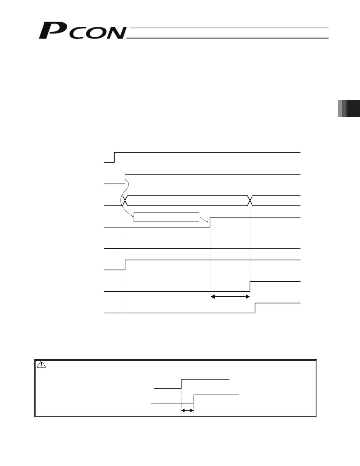
4.4 Operation Timings
(
)
4.4.1 Timing after Power ON
After conforming that the slider or rod is not contacting the mechanical end or transferred work is not interfering
with peripheral equipment, start operation following the steps below.
[1] Reset the emergency stop condition or put the motor drive power into a current-accessible state.
[2] Supply of 24 VDC of controller power supply: 24 V terminal, 0V terminal on the power supply terminal block
When 24 VDC is supplied in an emergency stop reset state, the controller is automatically put into the servo
ON condition internally.
[3] Initial setting of parameters (min.)
(Example) To change the feed speed during teaching:
Change the value of the parameter No. 35 (safety speed).
[4] Set the optimum values in the fields of “Position,” “Speed,” “Acceleration,” “Deceleration,” etc., with the PC or
teaching pendant.
4. Description of Operating Functions
Safety circuit condition
Controller power supply
24 VDC power ON
SV lamp (Front panel)
Controller ready output (PWR)
Pause input (STP)
Servo ON command (SON)
Operation ready (SV)
Position complete output
PEND
Emergency stop is reset
Illuminates in orange only for 2 sec and then goes out.
Initial parameter settings
Initial state 1
(Note 1) T1: Excited-pole detection time = 0.2 to 12 sec
Normally the detection of excited pole completes in approx. 0.2 sec, although the exact time varies
from one actuator to another due to individual differences and also depending on the load
condition. If the detection of excited pole has failed, the excited-pole detection operation will be
continued for up to 12 sec.
Green
Pause is cancelled
170 msec or less
Caution:
For the timing of emergency stop reset after power-on from the emergency stop condition,
the servo will be turned ON in T1 (Note 1) sec at maximum after emergency stop reset.
Emergency stop is reset
Servo ON condition
T1 (Note 1)
55
Page 68

Warning: Since a pulse motor is adopted as the driving motor, excited phase detection operation is
performed when the servo is turned ON for the first time after the power has been input.
What this means is that the actuator must be able to move when the servo is turned ON.
If the slider or rod is at the mechanical end or the transferring load is contacting any
surrounding device, excited phase detection cannot be completed successfully and the
actuator may operate erroneously or an excitation detection error may generate.
In this case, manually move the actuator to a position where it can move, before turning ON the
servo.
If the actuator has a brake, you must set the brake release switch to the ON side to forcibly
release the brake. However, exercise caution not to let you hand pinched or robot hand or work
damaged by the actuator dropping suddenly due to its dead weight. If the actuator cannot be
moved by hand, changing the setting of parameter No. 28 (direction of excited phase signal
detection) is an alternative solution. If you wish to change this parameter, consult IAI
beforehand.
Controller ready (PWR)
This signal indicates whether the controller is controllable from the outside.
0: Controller BUSY, 1: Controller READY
The controller is not generally put into a BUSY status.
Servo ON command (SON)
When this signal becomes “1,” the servo ON status is made.
Use this signal when the servo ON/OFF is required in constructing the safety circuit of the entire equipment.
Operation ready (SV)
4. Description of Operating Functions
This signal is a monitor signal indicating that the servo is ON and the motor is ready after the servo ON
command (SON) is input. The 1/0 status of this signal is synchronized with the lit/unlit status in green of the
SV lamp on the front panel.
56
Page 69
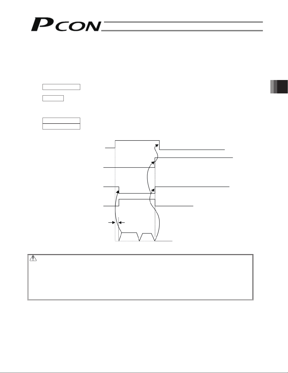
4.4.2 Home Return Operation
Since this controller adopts the incremental position detector (encoder), mechanical coordinates will be lost if the
power is cut off.
Because of this, it is required to establish the mechanical coordinates by performing home return operation
immediately after power-on.
To perform home return operation, input the home return command (HOME).
Operation timing
PLC processing 1: When the start button is pressed, the home return command signal (HOME) turns
ON.
Operation: [1] The actuator starts to move to the mechanical end near the home.
[2] After hitting the mechanical end the actuator turns back, and stops temporarily at the home
position.
→ The home return completion signal (HEND) turns ON.
PLC processing 2: The home return command signal (HOME) turns OFF.
PLC processing 3: Continuous operation starts.
Home return command (HOME)
Home return completion (HEND)
4. Description of Operating Functions
Position complete (PEND)
Actuator movement
Caution:
When performing home return operation, pay attention to the following:
[1] Confirm that there is no obstacle located in the direction of home return.
[2] Should there be an obstacle in the direction of home return, temporarily move the
[3] When the HOME signal is “1,” the PEND signal becomes “0” and the MOVE output
Moving (MOVE)
1 msec or less
Start of movement
[1]
Mechanical
end
[2]
Home
position
actuator in the home direction and remove the obstacle.
signal becomes “1.”
Return the HOME signal to “0” after confirming that the HEND has become “1” while the
HOME is “1.”
57
Page 70

Home return command (HOME)
When the rise edge (0→1) of this signal is detected, home return operation starts.
Upon completion of home return, the home return completion (HEND) signal will be output.
The HOME signal can be input any number of times even after the completion of home return.
(Note) Home return operation is automatically performed during the first positioning operation (CSTR
signal) without performing home return after power-on.
Home return completion (HEND)
This signal is “0” immediately after the power is input, and becomes “1” in either of the following two
conditions:
[1] Home return operation by the HOME signal has been completed.
[2] Home return operation associated with the first positioning operation by the CSTR signal has been
completed.
Once this signal has become “1,” it will not become “0” until the input power supply is cut off or the HOME
signal is input again.
Use this signal as the interlock signal before home return.
4. Description of Operating Functions
58
Page 71

4.4.3 Positioning Operation
A
First, turn on the 24 VDC power supply and set the position complete signal (PEND) to “1” by referring to 4.4.2.
Home return has not been completed immediately after the power is input. It is required to perform home return
by issuing the home return command (HOME) as described in 4.4.3.
If positioning start (CSTR signal) is output by specifying a position (position no. specification or direct specification
of position data), positioning will be performed to the specified position after performing home return operation.
Positioning operation is described below by taking the actuator with a stroke of 400 mm as an example.
Example of position table
Positioning
band
[mm]
No.
Position
[mm]
Speed
[mm/s]
cceleration
[G]
Deceleration
[G]
Push
[%]
1 5.00 300.00 0.30 0.30 0 0.10
2 200.00 300.00 0.30 0.30 0 0.10
3 380.00 300.00 0.30 0.30 0 0.10
Position command
Positioning start (CSTR)
Position complete (PEND)
Position complete position
Home return completion (HEND)
Position 1 Position 2
*
Position 1 Position 2
4. Description of Operating Functions
Comment
Moving (MOVE)
Speed
Actuator movement
Mechanical end Home position
Positioning band
Time
* T1: Set T1 to 0 msec or more in consideration of the scan time of the host controller.
59
Page 72
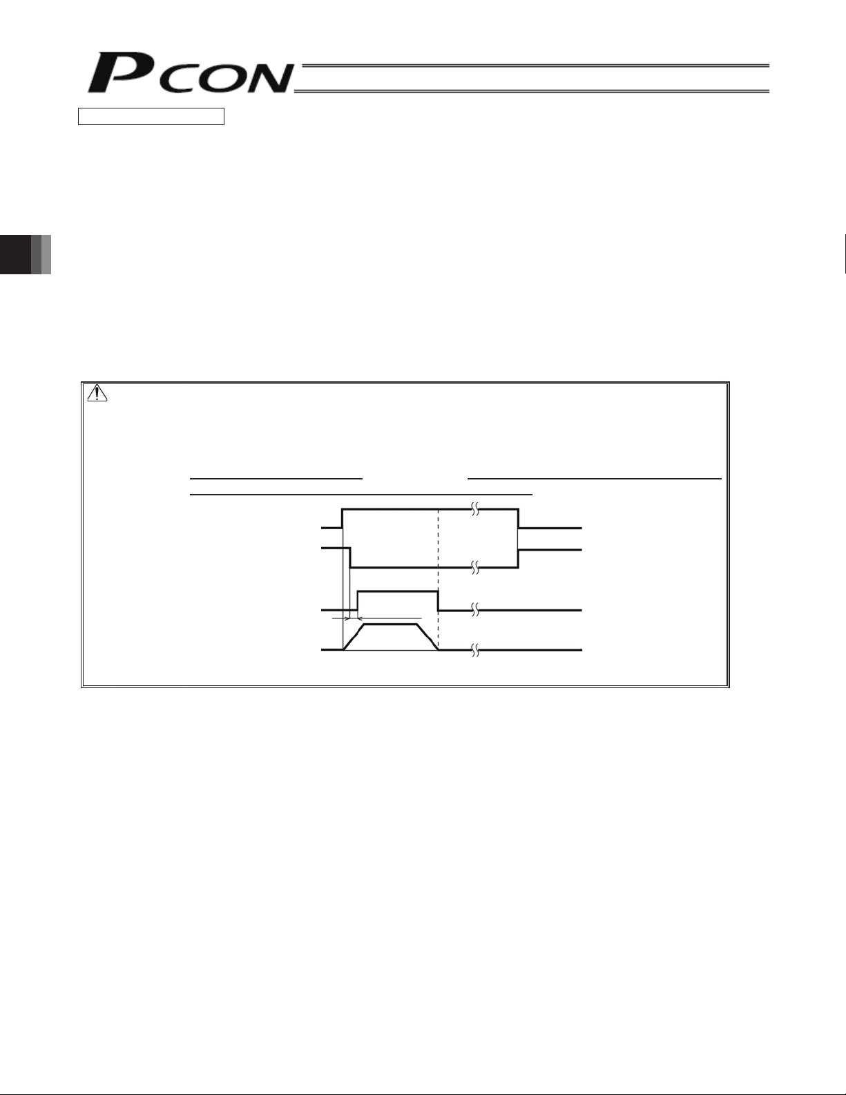
Operational Description
[1] If operation becomes ready after the power is turned on, the operation ready (SV) and position complete
(PEND) signals become “1.” After confirming that PEND is “1,” specify position 1 and set the positioning start
signal (CSTR) to 1.
To specify a position, specify the position number as six bits from PC1 to PC32 or directly specify the
numeric value in register PCMD.
→ Concurrently with the start of home return operation, PEND will become “0” and MOVE will become “1.”
[2] After confirming that MOVE has become “1,” set CSTR to “0.”
→ Immediately after the completion of home return operation (HEND will become “1”), positioning operation
to position 1 will start.
[3] When the set positioning band corresponding to the command value of position 1 is reached, PEND will
become “1”, MOVE will become “0” and the completed position number will be output as six bits from PM1 to
PM32 in register POSS.
[4] Then, specify position 2 and set CSTR to “1” in the same ways as [1]. Positioning operation to position 2 will
start.
[5] Positioning to position 2 will be completed in the same way as [3].
Caution: When the start signal turns ON, the position complete output will turn OFF and the
moving output will turn ON.
The start signal must be turned OFF with the confirmation that the moving output has
turned ON (the position complete output has turned OFF) while the start signal remains
ON.
If the start input remains ON
as shown below, the position complete output will not turn
ON even if the actuator movement has been completed.
4. Description of Operating Functions
Position complete
Start
Moving
Actuator
1 msec or less
Movement completed
60
Page 73

Positioning start (CSTR)
Upon detecting a rise edge (0→1) of this signal, the controller will read the target position number as a binary
code consisting of six bits from PC1 to PC32 (position no. specification register), and execute positioning to the
target position of the corresponding position data.
Before issuing a start command, all operation data such as the target position and speed must be set in the
position table using the PC or teaching pendant.
If this command is issued when home return operation has not been performed yet after the power input (the
HEND output signal is OFF), the controller will automatically perform home return operation before positioning to
the target position.
Moving (MOVE)
This signal is output while the servo is ON and the actuator is moving (also during home return, push & hold
operation or jogging).
Use the MOVE signal together with the PEND signal to allow the PLC to determine the actuator status.
The MOVE signal will become “0” when home return is completed and during a pause after a judgment is made
during push & hold operation that the work is being contacted as well as when positioning is completed.
Command position number (PC1 − PC32)
When a movement command is effected upon 0 → 1 of the CSTR signal, the six-bit binary code consisting of
signals PC1 to PC32 will be read as the command position number.
Completed position number (PM1 − PM32)
These signals can be used to check the completed position number when the PEND signal becomes “1.”
The signals are output as a binary code in the position no. status register.
Immediately after the power is input, all of the PM1 to PM32 signals are “0.”
All of PM1 to PM32 are also “0” when the actuator is moving.
As described above, this signal is output only when positioning is completed.
All of PM1 to PM32 will become “0” when the servo is turned OFF or an emergency stop is actuated. They will
return to “1” when the servo is turned ON again, provided that the current position is inside the positioning band
(INP) with respect to the target position. If the current position is outside the band, the signals will remain at “0.”
The signals will also become “1” when judgment is made as ON during push & hold operation or the work is not
contacted.
4. Description of Operating Functions
61
Page 74

Position Complete (PEND)
This signal indicates that the target position has been reached, and turns ON in the following condition:
[1] The operation ready signal (SV) is “1” and
[2] The current position deviation from each target position is within the positioning band or
[3] Work is contacted (not missed) during push & hold operation.
This signal is used as a trigger signal to peripheral equipment when the target position is reached.
Since making the positioning band value larger quickens a command to peripheral equipment by that amount, it is
effective as a means to reduce the tact time of the entire system.
When the servo turns ON after the power is input, this signal will become “1” because that position becomes the
target position. The signal will become “0” when positioning operation starts with the CSTR signal as “1.”
(Note) When the servo turns OFF or an emergency stop is actuated, PEND will become “0” once.
4. Description of Operating Functions
If the position deviation is within the positioning band when the servo is turned ON again, PEND will return
to “1.” If CSTR remains “1,” PEND will not return to “1” even when the current position deviation falls
within the positioning band and become “1” after CSTR becomes “0.”
Speed
Timing of position complete
signal turning ON
Target
position
Moving distance
Time
Positioning
band
62
Page 75

4.4.4 Push & Hold Operation
p
The actuator can continue to hold work in position while the rod end is pushing it, like an air cylinder.
Therefore, it can be used in the operation of work clamping or press fit process.
(1) Basic operation
After moving to the target position set as shown below, the actuator will move at the set push speed and push
work by the push amount set as the maximum.
When a push force reaches a certain value in the middle of push & hold operation, the position complete signal
will become “1” because push completion is judged with work being contacted.
Speed
Moving distance
Concept of push direction
Home
position
Actuator
Speed
Start
position
Push
s
Target position
Target
position
Push direction
Positioning band
(sign +)
Position at which the position complete signal
turns ON when the actuator contacts work and
push completion is judged
eed
Positioning band (maximum push amount)
Home
position
Actuator
Positioning band
Speed
Target
position
Push direction
(sign -)
4. Description of Operating Functions
Start
position
Start
position
When the negative
sign (-) is used
Positioning
band
Ta rg e t
Positioning
band
Position Position
Ta rg e t
Positioning
band
Positioning
band
When the negative
sign (+) is used
Start
position
When work is pushed in the direction which increases the coordinate value from the start position toward the
target position as shown above, the push direction will be positive (+). On the other hand, when work is pushed in
the direction which decreases the coordinate value, the push direction will be negative (-). If the positioning band
is entered with an incorrect sign, the position will deviate by twice the positioning band, as shown below.
Therefore, exercise sufficient caution.
63
Page 76

[1] Push & hold mode
Set a numeric value other than 0 in the “Push” field of the position table. (Current-limiting value)
In the case of numeric specification, specify “1” to bit 0 in the control flag specification register CTLF.
[2] Push speed
Set the push speed with parameter No. 34 (push speed).
(It is individually set on an actuator model basis before shipment.)
[3] Maximum push amount
Set the maximum push amount in the “Positioning band” field of the position table.
In the case of numeric specification, set it in the positioning band register (INP).
(Consider the position error when work is installed, or the depressed amount for work of elastic material.)
[4] Push direction
Sign of the “positioning band” in the position table
In the case of numeric specification, set “0” or “1” to bit 1 in the control flag specification register (CTLF).
[5] Push complete judgment
Push completion is judged with the motor generating torque (push force) and push time.
For the push force, set a current-limiting value (%) in the “Push” field of the position table. In the case of
numeric specification, set the value in the current-limiting value during push & hold operation register
(PPOW).
* Determine the push force according to the work characteristics (shape, material, etc.) and the
current-limiting value according to the diagram for the relationship between the “push force and
current-limiting value” of the actuator.
Set the value of the push stop judgment time to parameter No. 6.
4. Description of Operating Functions
(The factory setting is 255 msec.)
[6] Continuous push
When the push & hold operation is deemed to have completed, the position complete signal turns “1.”
However, the actuator will continue to push the work until the next movement command is issued (= a
command position number is specified and a positioning start signal is output).
64
Page 77

(2) Work is not contacted (missed)
If work is not contacted even though the actuator has moved the distance by the set positioning band (when
the motor current does not reach the current-limiting value during push & hold operation), the positioning
complete signal will not be output. However, the completed position number will be output.
At this time, the PSFL bit of the device status register (DSS1) becomes “1.”
Accordingly, perform timeout check process for ample period on the host PLC side.
Speed
Moving distance
Target position
If work is not contacted, the position
complete signal will not be output.
Positioning band (maximum push amount)
(3) Work moves during push & hold operation
(1) Work moves in the pushed direction
If work moves in the pushed direction after push & hold operation has once been completed, the actuator will
push the work within the positioning band.
If the current during movement drops below the current-limiting value during push & hold, the position
complete signal will turn OFF. The signal will turn ON again when the current rises to or above the limiting
value.
Speed
Position at which push & hold operation
is initially judged as completed
Moving distance
If work is moved backward, the actuator will
push it within the positioning band.
4. Description of Operating Functions
Positioning band (maximum push amount)
Target position
(2) Work moves in the opposite direction
(Actuator is pushed back by the reactive force of the work)
If the actuator is pushed back after push & hold operation has once been completed because the actuator
thrust is smaller than the reactive force of the work, the actuator will be pushed back all the way until its
thrust balances out with the reactive force of the work. At this time, the position complete signal will remain
ON.
Speed
Position at which push & hold operation
is initially judged as completed
Moving distance
Positioning band (maximum push amount)
Target position
(Note) If the actuator is pushed back to the target position, an alarm will be generated.
65
Page 78

(4) Positioning band is entered with an incorrect sign
If the positioning band is entered with an incorrect sign, the position will deviate by twice the positioning band,
as shown below. Therefore, exercise sufficient caution.
Speed
Intended operation
Moving
distance
Actual operation
Positioning band Positioning band Positioning band
Actually moving distance
(missed)
Target position
(5) Pushing back is performed after push & hold operation by specifying the relative coordinate
The reference position for the relative coordinate specification is not the current position at which the
actuator stops after push & hold operation has completed but the target position of the position number for
push execution. Exercise sufficient caution for this.
In the example above, if the position number is set as the relative coordinate minus 40 mm, the actuator will
move to the position of 240 mm obtained by subtracting 40 from 280.
However, if push is specified, the actuator will perform relative movement from the stop position.
Speed
4. Description of Operating Functions
Pushing-back
operation
Push & hold complete position
66
Page 79

The graphs below show the relationships of current-limiting value [%] and push force [N] of respective actuators.
Note: For the relationships applicable to RCP3 controllers, refer to the operation manual for RCP3.
• Slider Type
(1) SA5C/SA6C/SS7C types (2) SA7C Type
Low-speed type
(Lead: 3 mm)
Low-speed type
(Lead: 4 mm)
4. Description of Operating Functions
Push force (N)
Push force (N)
Current-limiting value (ratio, %)
Medium-speed type
(Lead: 6 mm)
Current-limiting value (ratio, %)
High-speed type
(Lead: 12 mm)
Push force (N)
Current-limiting value (ratio, %)
Medium-speed type
(Lead: 8 mm)
Push force (N)
Current-limiting value (ratio, %)
High-speed type
(Lead: 16 mm)
Push force (N)
Current-limiting value (ratio, %)
Push force (N)
Current-limiting value (ratio, %)
Caution: Precision of each push force at standstill is not guaranteed, and the above are reference
values only.
Exercise caution that if the push force is too small, the actuator may malfunction during
push-motion operation due to slide resistance, etc.
Find the maximum current-limiting value of your controller from the applicable graph above.
The minimum value is 20%
67
Page 80
(3) SS8C type
Push force (N)
Push force (N)
Low-speed type
(Lead: 5 mm)
Current-limiting value (ratio, %)
Medium-speed type
(Lead: 10 mm)
4. Description of Operating Functions
Current-limiting value (ratio, %)
High-speed type
(Lead: 20 mm)
Push force (N)
Current-limiting value (ratio, %)
Caution: Precision of each push force at standstill is not guaranteed, and the above are reference
values only.
Exercise caution that if the push force is too small, the actuator may malfunction during
push-motion operation due to slide resistance, etc.
Find the maximum current-limiting value of your controller from the applicable graph above.
The minimum value is 20%
68
Page 81
• Rod type
(1) RA2C type (2) RA3C type
Push force (N)
Push force (N)
Current-limiting value (ratio, %)
Current-limiting value (ratio, %)
Low-speed type
(Lead: 2.5 mm)
4. Description of Operating Functions
Medium-speed type
(Lead: 5 mm)
Push force (N)
Current-limiting value (ratio, %)
Caution: Precision of each push force at standstill is not guaranteed, and the above are reference
values only.
Exercise caution that if the push force is too small, the actuator may malfunction during
push-motion operation due to slide resistance, etc.
Find the maximum current-limiting value of your controller from the applicable graph above.
The minimum value is 20%
69
Page 82

(3) RA4C type (4) RA6C type
Low-speed type
(Lead: 2.5 mm)
Low-speed type
(Lead: 4 mm)
Push force (N)
Current-limiting value (ratio, %)
Medium-speed type
(Lead: 5 mm)
Push force (N)
4. Description of Operating Functions
Current-limiting value (ratio, %)
High-speed type
(Lead: 10 mm)
Push force (N)
Current-limiting value (ratio, %)
Medium-speed type
(Lead: 8 mm)
Push force (N)
Current-limiting value (ratio, %)
High-speed type
(Lead: 16 mm)
Push force (N)
Push force (N)
Current-limiting value (ratio, %)
Current-limiting value (ratio, %)
Caution: Precision of each push force at standstill is not guaranteed, and the above are reference
values only.
Exercise caution that if the push force is too small, the actuator may malfunction during
push-motion operation due to slide resistance, etc.
Find the maximum current-limiting value of your controller from the applicable graph above.
The minimum value is 20%
70
Page 83
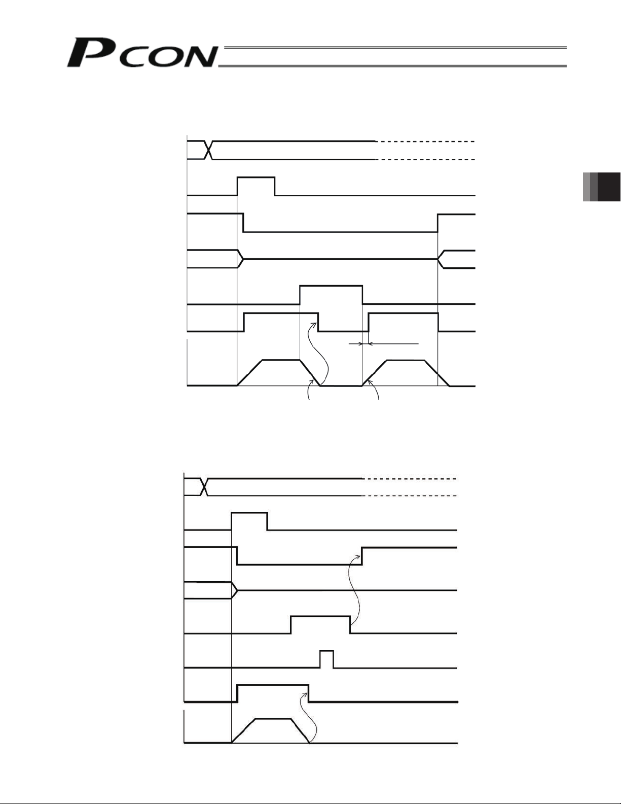
4.4.5 Pause
The actuator will decelerate to a stop by setting the pause command (STP) to “1” during its operation.
Since the remaining movement is retained, setting STP to “0” again will restart the remaining movement.
Command position
Positioning start (CSTR)
Position complete (PEND)
Completed position
Pause command (STP)
4. Description of Operating Functions
Moving (MOVE)
Speed
Actuator movement
Deceleration to a stop Remaining movement start
4 msec or less
The remaining movement can be cancelled by setting the alarm reset (RES) to “1” during pause.
When a reset of the pause command (STP) is subsequently recognized, the position complete (PEND) signal will
turn “1” within approx. 1 msec thereafter.
(The controller will detect a rise of the reset signal and cancel the remaining movement.)
Command position
Positioning start (CSTR)
Position complete (PEND)
Completed position
Pause command (STP)
Approx. 1 msec
Reset (RES)
Moving (MOVE)
Speed
Actuator movement
71
Page 84

4.4.6 Speed Change during Movement
A
Speed control involving multiple speed levels is possible in a single operation. The actuator speed can be
decreased or increased at a certain point during movement.
However, the position at which to implement each speed change must be set.
Position 1 Position 2 Position 1 Position 2 Position 1 Position 2 Position 3
Applications refer to the case where the material of transferred work is soft or where it is not desired to give
vibrations or an impact to the work having the easy-to-topple shape.
(Example) If positioning is performed at position 2 (300 mm from the home position), move the actuator at a
speed of 200 mm/sec up to position 1 in mid-process (200 mm from the home position) and
subsequently at a speed of 20 mm/sec.
Example of position table
No.
Position
[mm]
Speed
[mm/s]
1 * * * * * *
2 200.00 300.00 0.30 0.30 0 20.00
4. Description of Operating Functions
3 380.00 20.00 0.30 0.30 0 0.10
cceleration
[G]
Deceleration
[G]
Push
[%]
Positioning
band
[mm]
Comment
Position command
Positioning start (CSTR)
Position complete (PEND)
Completed position
Moving (MOVE)
Actuator movement
* T1: Set T1 to 0 msec or more in consideration of the scan time of the host controller.
Speed
Position 1 Position 2
*
Position 1
*
280 mm
Position 1
(200 mm)
Position 2
Position 2
(300 mm)
72
Page 85

(Note) If the pause command is output during home return operation, the movement command will be retained
when the actuator has not pushed the mechanical end but operation must again begin with home return
after the actuator has pushed the mechanical end and performed pushing-back operation.
Alarm reset (RES)
An alarm can be reset at a rise edge of 0 to 1.
If the cause for the alarm is not resolved, the alarm status will be entered again.
If an alarm is reset during pause, the remaining movement will be cancelled.
Caution: [1] If the start signal (CSTR) is set to “1,” the position complete signal (PEND) will be “0” and
the moving signal (MOVE) will be “1.”
Set the start signal (CSTR) to “0” after confirming that the moving signal (MOVE) has
become “1” while CSTR is “1.”
[2] If the positioning band at position 1 is made large, the actuator speed can be changed
smoothly without stopping it temporarily.
4. Description of Operating Functions
73
Page 86

4.4.7 Operation at Different Acceleration and Deceleration Settings
(1) If the operation by position number specification is used, the acceleration and deceleration can be set
separately in the position table.
(2) If the operation by numeric specification is used, the acceleration/deceleration data (set on register 9906H)
will become valid during data receiving. Therefore, to make the deceleration different from the acceleration,
change the acceleration/deceleration data during movement.
(Example)
Position command
Position complete (PEND)
Completed position
4. Description of Operating Functions
Moving (MOVE)
Speed
Actuator movement
Position 1
Acceleration DecelerationAcceleration/deceleration command
Position 1
Position 1
74
Acceleration Deceleration
Page 87

4.4.8 Zone Signal
This signal is output (becomes “1”) when the current position of the actuator is inside the set zone, and it can be
used in the following application:
[1] Interlock signal to prevent interference with peripheral equipment
[2] Trigger signal to reduce the tact time for peripheral equipment
[3] Judgment of work not being contacted during push & hold operation
[4] End-point determination in constant pitch feeding of work placed in alignment
(Note) In the constant pitch feeding, the “Position” field of the position table indicates the relative amount
but the zone setting establishes the absolute coordinate from the home position.
Zone signal (ZONE1, 2)
(PZONE, ZONE1, ZONE2)
Actuator operation
Home
Zone setting
(negative side)
Zone setting
(positive side)
Positive direction
4. Description of Operating Functions
Setting Zone signal*
Individual zone boundary in position
table
Zone boundary 1 of user parameter
(parameter No. 1, No. 2)
Zone boundary 2 of user parameter
(parameter No. 23, No. 24)
Position zone
output
PZONE
Zone output 1
ZONE1
Zone output 2
ZONE2
Position no.
specification mode
Numeric
specification mode
×
* The zone signal is output to the zone status register (address 9013H).
It becomes “1” when the current position is inside the zone range or becomes “0” when the current
position is outside the zone range.
The signal becomes valid after the completion of home return. It is valid even when the servo is OFF,
provided that home return has been completed.
75
Page 88

4.4.9 Pitch Feeding by Relative Coordinate Specification
For the target position in the position table, relative coordinate specification is also available. Therefore, it can be
used in constant-pitch positioning (constant-pitch feeding).
(1) Operation example in the position no. The following is the description of an example of positioning
with a 50 mm pitch from position No. 1. Create a position table as shown below. Operational
completion is judged by PLC’s executing count control. The combined use of the zone signal
allows a double check specification mode.
Forward end
direction
Position 1
50 mm
pitch
Last work
4. Description of Operating Functions
Zone output signal
Set the coordinate value for the next last work to the positive-side boundary value.
Example of position table
No.
0 * * * 0
1 100.00 300.50 99.50 0
2 50.00 300.50 99.50 1
Position
[mm]
=
*Indicates the relative coordinate specification with the teaching pendant.
Zone +
[mm]
Zone –
[mm]
Incremental Comment
76
Page 89
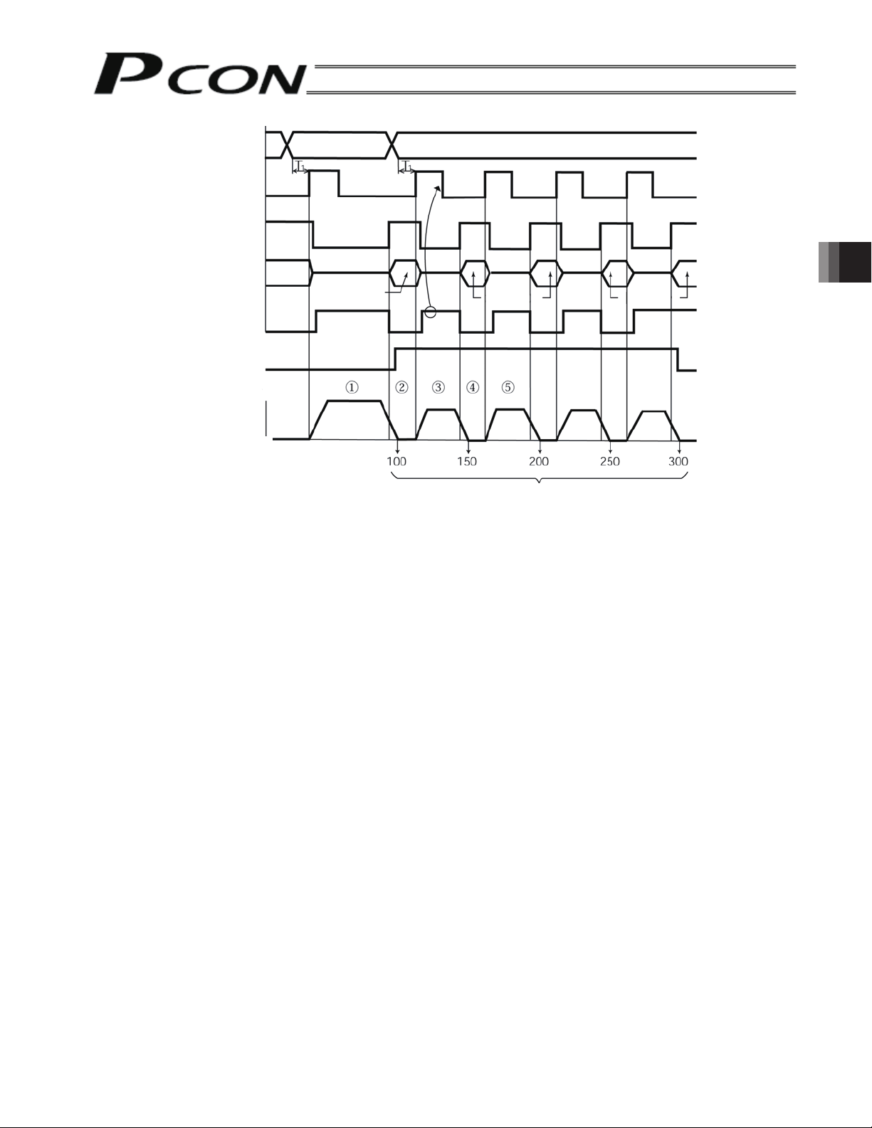
Position command
Positioning start (CSTR)
Position complete (PEND)
Completed position
Moving (MOVE)
Zone signal (PZONE)
Speed
Position 1 Position 2
*
Position 1
*
Position 2 Position 2
4. Description of Operating Functions
Actuator movement
Distance from home
Time
* T1: Set T1 to 0 msec or more in consideration of the scan time of the host controller.
[Operational description]
[1] Perform positioning operation to position 1 (100.00 mm).
[2] Upon completion of positioning to position 1, the position complete signal (PEND) will become “1.”
The zone signal (PZONE) will also become “1.”
After changing the position number from 1 to 2, set the start signal (CSTR) to “1.”
[3] When movement starts, (PEND) will change from “1” to “0” and the moving signal (MOVE) will change from
“0” to “1.” After confirming that (MOVE) has become “1,” set the start signal (CSTR) to “0.”
[4] When the actuator has moved only 50 mm, (PEND) will become “1” and (MOVE) will become “0” again. At
this time, the PLC counts the first time of movement.
Then, set the (CSTR) for the second 50 mm movement to “1.”
[5] Repeat the operations of [3] and [4].
The PLC checks the zone signal (PZONE) status when positioning has been completed and judges that the
current position is the last work position if the signal has become “0.”
If the number of counts on the PLC side does not agree with the zone signal status, it is assumes that the signal
timing is not synchronized.
77
Page 90

(2) Notes on positioning operation
g
Selecting/entering a position number using relative coordinates during positioning will cause the actuator to move
to the position corresponding to the initial position plus the relative movement. (If the relative movement is a
negative value, the actuator will move to the position corresponding to the initial position minus the relative
movement.)
Example) If the start signal for movement to position 2 is input while the actuator is moving to position 1, the
actuator will move to the position 40 mm from the home.
<Position table by teaching pendant>
Position command
Positioning start
Position complete
Completed position
Movin
Speed
Actuator movement
Position 1 Position 2
4. Description of Operating Functions
If the start signal for movement to a position number using relative coordinates is input multiple times during
positioning, the actuator will move to the position corresponding to the initial position plus the relative movement ×
number of times the signal was input.
Example) If the start signal for movement to position 2 is input twice while the actuator is moving to position 1, the
actuator will move to the position 50 mm from the home.
Distance from home: 40
Position 2
Distance
Position
Speed
Position command
Positioning start
Position complete
Completed position
Moving
Speed
Actuator movement
Position 1 Position 2
Position 2
Distance
Distance from home: 50
78
Page 91
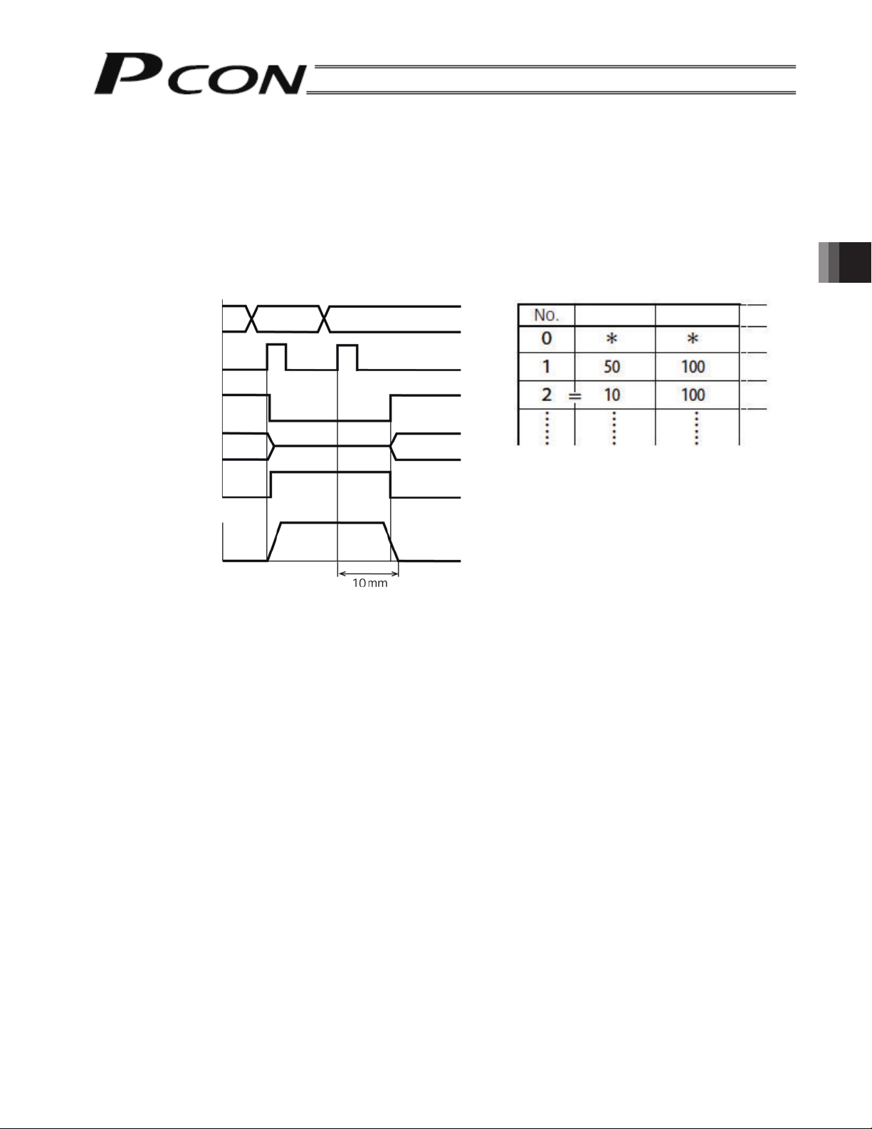
(3) Notes on push & hold operation
If the start signal is input with a position number using relative coordinates (push specification) selected/entered
while the actuator is moving in the push & hold mode, the actuator will move to the position corresponding to the
position at the time of start input plus the relative movement. Therefore, the end position will become
indeterminate.
Example) If the start signal for movement to position 2 is input while the actuator is moving to position 1 in the
push & hold mode, the actuator will move to the position 10 mm from where it was when the input
signal was input.
Position command
Positioning start
Position complete (PEND)
Completed position
Moving (MOVE)
Speed
Actuator movement
Position 1
Position 2
Position 2
Distance
<Position table by teaching pendant>
Position
Speed
4. Description of Operating Functions
79
Page 92

4.4.10 Power-saving Mode at Standby Positions
One general characteristic of pulse motors is that their holding current at standstill is higher compared to AC servo
motors.
Accordingly, as part of our energy-saving efforts IAI has developed a special mode to reduce the power
consumption at standstill when the actuator is programmed to stop for a long time at a standby position.
Use this mode after confirming that doing so will not negatively affect any part of the system.
The power-saving mode, or specifically full-servo control method, can be selected in the following three
conditions:
(1) The actuator is waiting with the servo turned ON after the power was input (but before the home return is
completed)
(2) The actuator is waiting after completing the home return operation initiated by the HOME input signal.
(3) The actuator is waiting at the target position after completing the positioning to that position
Set 0 or 4 to the parameter No. 53.
The power-saving mode is disabled (the actuator is fully stopped) 0
Full-servo control mode 4
Full-servo Control Mode
You can lower the holding current of a pulse motor by servo-controlling the motor.
Although how much the current comes down varies depending on the actuator model, load condition, etc.,
the holding current normally drops to approximately one-half to one-quarter.
4. Description of Operating Functions
Since the servo remains ON, position deviation will not occur when this mode is used.
You can check the actual holding current on the current monitor screen of the PC software.
Take note, however, that micro-vibration or abnormal noise may occur if an external force is applied or
depending on the position where the actuator is stopped. Should you notice any micro-vibration or abnormal
noise that might affect your system, do not use this mode.
Set value
Caution: In the case of push-motion operation, the full-servo control mode will be disabled after the
actuator has successfully completed the push operation. The mode will be enabled, however,
if the actuator has missed the work.
80
Page 93

4.5 Notes on ROBO Grippers
(1) Finger Operation
[1] Definition of Position
With the two-finger specification, the stroke represents the sum of travels of both fingers.
Accordingly, the travel of each finger is one-half the stroke.
The specified position indicates the travel of each finger from the home position toward the closing side.
For example, the maximum command value is 5 mm for the GRS type and 7 mm for the GRM type.
[2] Definition of Speed and Acceleration
Command values apply to each finger.
With the two-finger type, the actual speed (relative speed) and acceleration are twice the command values.
[3] Operation Mode in Gripper Applications
In applications where the ROBO Gripper is to grip the work, be sure to select the “push mode.”
(Note) If the “positioning” mode is selected, a servo error may generate while the actuator is gripping the
work.
[Graphs of Gripping Force and Current-limiting Value]
4. Description of Operating Functions
Gripping force (N)
Current-limiting value (ratio, %)
Gripping force (N)
Current-limiting value (ratio, %)
Gripping force (N)
Current-limiting value (ratio, %)
Gripping force (N)
Current-limiting value (ratio, %)
Gripping force (N)
Current-limiting value (ratio, %)
Gripping force (N)
Current-limiting value (ratio, %)
81
Page 94

(2) Removing the Gripped Work
This gripper is structured in such a way that it will maintain its gripping force on the work through the self-lock
function even when the servo is turned OFF or controller power is cut off.
If the gripped work must be removed while the power is cut off, do so by turning the open/close screw or taking
out the finger attachment on one side.
[2-finger Type]
Turn the open/close screw or take out the finger attachment on one side.
Open/close screw
Use a screwdriver to turn the screw
counterclockwise.
[3-finger Type]
4. Description of Operating Functions
Take out one of the finger attachments.
Finger attachment.
Open direction
Lock bolt
Lock bolt
Finger attachment
.
82
Page 95

4.6 Using a Rotary Actuator in the Multi-rotation Specification
Rotary actuators that support the multi-rotation specification let you specify multi-rotation operation or
limited-rotation operation.
(1) Home Return
When a home return command is issued, the actuator moves in the home return direction to detect the limit
switch and upon detecting the limit switch, the actuator reverses its direction. Thereafter, the actuator
travels to a position where the limit switch turns off again, and then move the distance corresponding to the
home return offset in parameter No. 22 to complete the home return.
(2) Operation Commands
4. Description of Operating Functions
Limited-rotation specification
(Normal mode [selected by parameter No. 79])
Push-motion operation is possible. Push-motion operation is not possible.
Absolute coordinate specification -0.15° ~ 360.15° Absolute coordinate specification 0.00° ~ 359.99°
Relative coordinate specification -360.15° ~ 360.15° Relative coordinate specification -360.00° ~ 360.00°
Multi-rotation operation
(Index mode [selected by parameter No. 79])
Note
Pay attention to the setting of the PIO pattern parameter for the controllers listed below.
On the following types of controllers, relative coordinate specification cannot be used in the PIO patterns
specified:
[1] PCON-C/CG: PIO pattern = 5 (User parameter No. 25)
[2] PCON-CY: PIO pattern = 0 (User parameter No. 25)
• Rotational axes of simple absolute unit specification do not support the index mode, so multi-rotation
specification cannot be specified for these axes.
Applicable Models
Actuator
RCP2-RTBL-I-28P-20-360-* PCON-C-28PI-*
RCP2-RTBL-I-28P-30-360-* PCON-CG-28PI-*
RCP2-RTCL-I-28P-20-360-* PCON-CY-28PI-*
RCP2-RTCL-I-28P-30-360-*
Controller
PCON-SE-28PI-*
83
Page 96

5. Parameter Settings
5.1 Parameter Table
Parameters are classified into four types according to their content.
a: Parameter relating to the actuator stroke range
b: Parameter relating to the actuator operating characteristics
c: Parameter relating to the external interface
d: Servo gain adjustment
*
No. Category Symbol Name Unit
1 a ZONM Zone boundary 1+ mm
2 a ZONL Zone boundary 1- mm
3 a LIMM Soft limit+ mm
4 a LIML Soft limit- mm
5 a ORG Home return direction (0: Reverse/1: Forward)
6 b PSWT Push & hold stop judgment period msec
7 d PLG0 Servo gain number
8 b VCMD Default speed mm/sec
9 b ACMD Default acceleration/deceleration G
5. Parameter Settings
10 b INP Default positioning band (in-position) mm
12 b SPOW Current-limiting value at standstill after positioning %
13 b ODPW Current-limiting value during home return %
16 c BRSL SIO communication speed bps
17 c RTIM Minimum delay time for slave transmitter activation msec
18 b LS Home position sensor input polarity
22 a OFST Home return offset mm
23 a ZNM2 Zone boundary 2+ mm
24 a ZNL2 Zone boundary 2- mm
28 b PHSP1
29 b PHSP2 Excitation-phase signal detection time msec
31 d VLPG Speed loop proportional gain
32 d VLPT Speed loop integral gain
33 d TRQF Torque filter time constant
34 b PSHV Push speed mm/sec
35 b SAFV Safety speed mm/sec
39 c FPIO1 Position complete signal output method (0: PEND: 1: INP)
42 b FPIO4 Enable function (0: Valid/1: Invalid)
43 b AIOF Home position check sensor input polarity
45 c SIVM Silent interval magnification times
46 b OVRD Speed override %
53 b CTLF Default stop mode
77 b LEAD Ball screw lead length mm
78 b ATYP Axis operation type
79 b ATYP Rotation axis mode selection
80 b ATYP Rotation axis shortcut selection
83 b ETYP ABS unit (0: Not used/1: Use)
* The numbers are displayed on the PC software screen but not on the teaching pendant.
The missing numbers are not used and omitted.
The category codes are provided only for convenience and not displayed on either the PC software screen or teaching
pendant.
Default movement direction for excitation-phase signal
detection (0: Reverse/1: Forward)
Default factory setting
Effective actuator length
Effective actuator length
Effective actuator length
Effective actuator length
(In accordance with the specification
⎯
⎯
⎯
⎯
⎯
⎯
⎯
⎯
⎯
⎯
⎯
⎯
⎯
⎯
at the time of order)
255
Set individually in accordance with
the actuator characteristics
Set individually in accordance with
the actuator characteristics
Set individually in accordance with
the actuator characteristics
0.10
35
Set individually in accordance with
the actuator characteristics
38400
Set individually in accordance with
the actuator characteristics
Set individually in accordance with
the actuator characteristics
Effective actuator length
Effective actuator length
Set individually in accordance with
the actuator characteristics
10
Set individually in accordance with
the actuator characteristics
Set individually in accordance with
the actuator characteristics
Set individually in accordance with
the actuator characteristics
Set individually in accordance with
the actuator characteristics
100
0 (PEND)
1 (Invalid)
(In accordance with the specification
at the time of order)
0 (Invalid magnification)
100
0 (Trapezoid)
Set individually in accordance with
the actuator characteristics.
Set individually in accordance with
the actuator characteristics.
Set individually in accordance with
the actuator characteristics.
Set individually in accordance with
the actuator characteristics.
Set individually in accordance with
the actuator characteristics.
5
84
Page 97
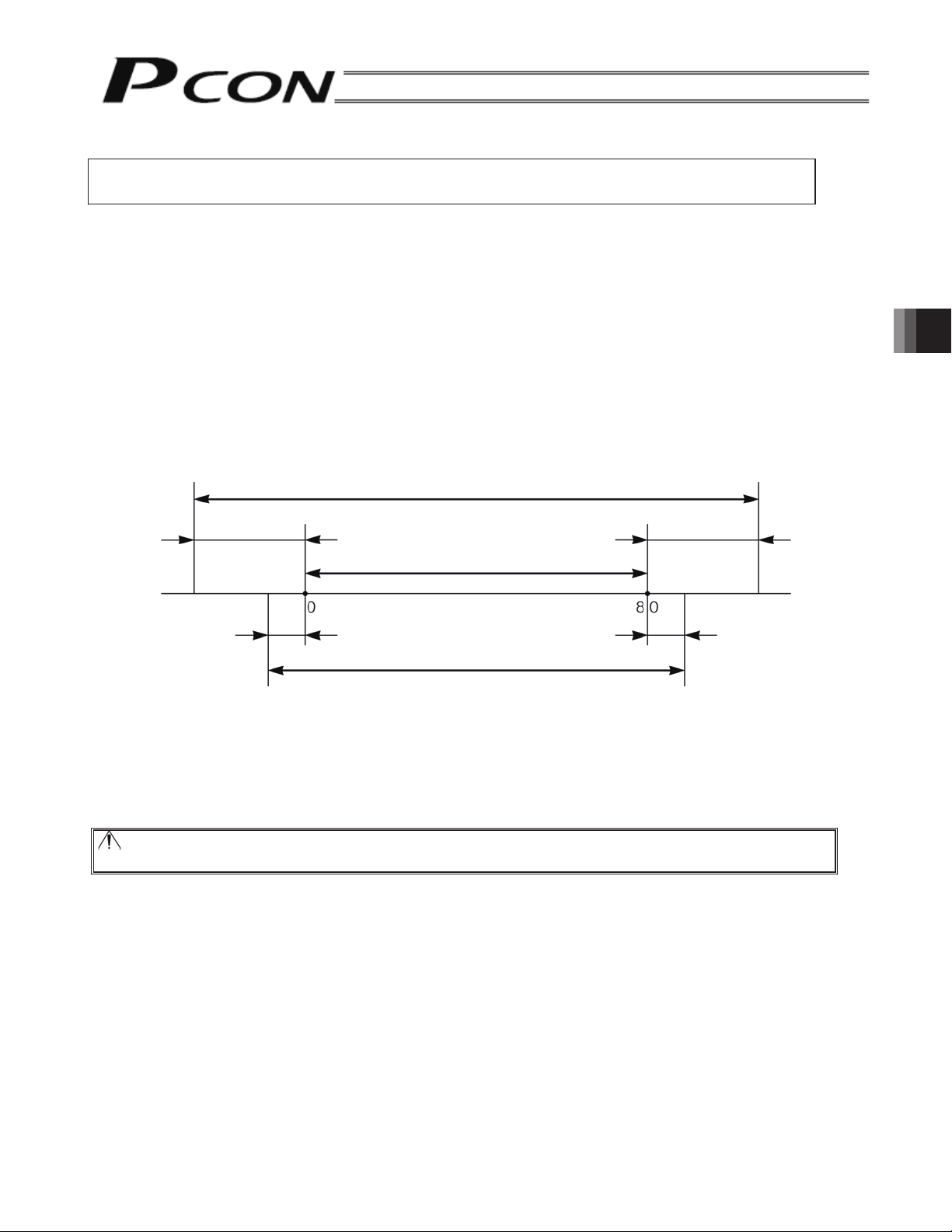
5.2 Parameter Settings
If a parameter has been changed, always restart the controller using a software reset command or by
reconnecting the power.
5.2.1 Parameters Relating to the Actuator Stroke Range
Soft limit (No. 3/4 LIMM/LIML)
Set the soft limit in the positive direction in parameter No. 3, and that in the negative direction in parameter No. 4.
The factory setting for the soft limits conforms to the effective actuator length. Change the settings, as necessary,
to prevent collision with an obstacle or when the actuator must be stroked slightly beyond its effective length.
An incorrect soft limit setting will cause the actuator to collide into the mechanical end, so exercise sufficient
caution. The minimum setting unit is “0.01 [mm].”
(Note) To change a soft limit, set a value corresponding to 0.3 mm outside of the effective range.
Example) Set the effective range to between 0 mm and 80 mm
Parameter No. 3 (positive side) 80.3
Parameter No. 4 (negative side) -0.3
Soft limits set in the controller
5. Parameter Settings
Approx.
0.3 mm
Approx. 0.1 mm
Effective range
Approx. 0.1 mm
Allowable jogging/inching range after home return
Approx.
0.3 mm
Home return direction (No. 5 ORG)
Unless specified by the user, the home return direction is set to the motor direction at the factory. Should a need
arise to change the home direction after the actuator has been assembled into your system, reverse the setting in
parameter No. 5 between “0” and “1.”
Also change the parameters for home return offset, soft limits and direction of excited phase signal detection if
necessary.
Caution: If the home direction is reversed, all position data that have been input will be retained.
The home direction cannot be reversed for rod-type actuators.
85
Page 98
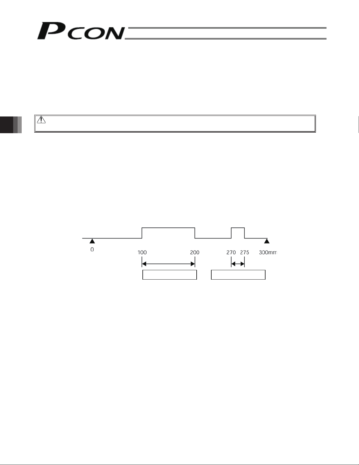
Home return offset (No. 22 OFST)
The controller is shipped from the factory with an optimal value set in parameter No. 22, so the distance from
each mechanical end to the home becomes uniform.
The minimum setting unit is 0.01 [mm].
The home return offset can be adjusted in the following condition:
[1] Want to align the actuator home and the system’s mechanical home after the actuator has been assembled
into the system
[2] Want to set a new home after reversing the factory-set home direction
[3] Want to eliminate a slight deviation generated after replacing the actuator
Caution: If the home return offset has been changed, the soft limit parameters must also be adjusted
accordingly.
Zone boundary (1: No. 1/2 ZONM/ZONL, 2: No. 23/24 ZNM2/ZNL2)
Set the zone in which a zone output signal (ZONE1 or ZONE2) will turn ON.
The zone signal turns ON only when the current coordinate position is inside the negative (-) boundary and
positive (+) boundary settings.
The positive and negative boundaries for the ZONE1 signal are set in parameter No. 1 and No. 2, respectively.
The positive and negative boundaries for the ZONE2 signal are set in parameter No. 23 and No. 24, respectively.
The minimum setting unit is 0.01 [mm].
5. Parameter Settings
Example) Use ZONE1 as an intermediate limit switch inside 100 and 200 mm, and use ZONE2 as a simple ruler
inside 270 and 275 mm, with an actuator having a 300 mm stroke
Parameter No. 1 (positive side) 200, parameter No. 2 (negative side) 100
Parameter No. 23 (positive side) 275, parameter No. 24 (negative side) 270
(Home)
ZONE1 turns ON ZONE2 turns ON
86
Page 99

5.2.2 Parameters Relating to the Actuator Operating Characteristics
Default speed (No. 8 VCMD)
The factory setting is the rated speed of the actuator.
When a target position is written to an unregistered position table or the current position is read in the teaching
mode, the setting in this parameter will be used as the speed data for the applicable position number.
To reduce the default speed from the rated speed, change the setting in parameter No. 8.
Default acceleration/deceleration (No. 9 ACMD)
The factory setting is the rated acceleration/deceleration of the actuator.
When a target position is written to an unregistered position table or the current position is read in the teaching
mode, the setting in this parameter will be used as the acceleration/deceleration data for the applicable position
number.
To reduce the default acceleration/deceleration from the rated acceleration/deceleration, change the setting in
parameter No. 9.
Default positioning band (in-position) (No. 10 INP)
The factory setting is “0.10 [mm].”
When a target position is written to an unregistered position table or the current position is read in the teaching
mode, the setting in this parameter will be used as the positioning band data for the applicable position number.
Increasing the default positioning band will allow the position complete signal to be output early. Change the
setting in parameter No. 10 as necessary.
Caution: For the positioning band, set the value greater than that of the encoder resolution.
Setting it smaller may cause a servo error.
5. Parameter Settings
Current-limiting value during home return (No. 13 ODPW)
A current value appropriate for the standard specification of the actuator has been set at the time of shipment.
Increasing the value set in this parameter increases the home return torque.
This parameter need not be changed in normal conditions, but in certain situations such as when the slide
resistance increases due to the affixing method, load condition, etc., of the actuator used vertically, the home
return may complete before the correct position. In this case, the value set in parameter No. 13 must be
increased.
(As a guide, the set value should not exceed 75%.)
Current-limiting value at standstill after positioning (No. 12 SPOW)
A current value appropriate for the standard specification of the actuator has been set at the time of shipment.
Increasing the value set in this parameter increases the holding torque at standstill.
This parameter need not be changed in normal conditions, but if a large external force is applied to the actuator at
standstill, hunting may occur. In this case, the value set in parameter No. 12 must be increased.
(As a guide, the set value should not exceed 70%.)
Speed override (No. 46 OVRD)
Use this parameter to move the actuator to prevent danger at the trial run startup time.
When a movement command is issued from the PLC, an override can be applied to the movement speed set in
the “Speed” field of the position table by the setting in parameter No. 46.
Actual movement speed = [Speed set in the position table]
Example) Value in the “Speed” field of the position table: 500 (mm/s)
Setting in parameter No. 46: 20 (%)
In this case, the actual movement speed becomes 100 mm/s.
The minimum setting unit is 1% and the input range is 1 to 100 (%). The factory setting is 100%.
[setting in parameter No. 46] 100
(Note) This parameter is invalid for the movement command by the PC or teaching pendant and the movement command by
direct numeric specification.
When the PC or teaching pendant is used, operation can be performed by setting a speed ratio on such a tool.
87
Page 100
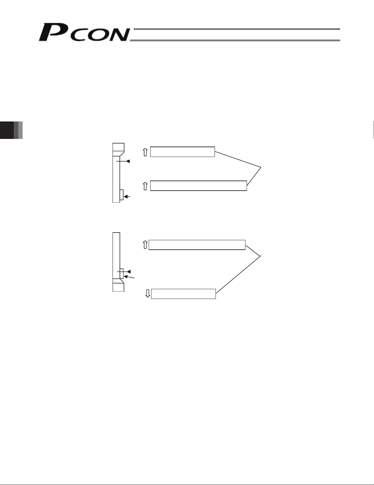
• Default movement direction for excitation-phase signal detection (No. 28 PHSP1)
Excitation-phase detection is performed at the first servo ON after the power is input. Define the detection
direction at this time. This setting need not be changed in normal conditions of use. However, if the actuator
contacts the mechanical end or an obstacle and cannot be moved by hand when the power is input, this setting
must be changed to the direction in which the motor is easier to operate.
Set the value of parameter No. 28 to 0 or 1. If the detection direction is the same as the home return direction, set
the same value as that in parameter No. 5 (home return direction).
To make this direction opposite the home return direction, set a value other than that in parameter No. 5 (home
return direction).
(Example 1) Motor upper-side vertical installation + If the power is input when the slider is contacting the lower
mechanical end:
5. Parameter Settings
(Example 2) Motor lower-side vertical installation + If the power is input when the slider is contacting the lower
mechanical end
• Excitation-phase signal detection time (No. 29 PHSP2)
Excitation-phase detection is performed at the first servo ON after the power is input. Define the detection time at
this time.
The factory setting is the detection time in accordance with the standard specifications of the actuator and this
setting need not be changed in normal conditions of use.
Should an excitation detection error or a malfunction occur at the first servo ON after the power is input, the
detection time set in parameter No. 29 can be changed as one of the remedies.
Before changing this parameter, contact us.
Upper
Lower
Upper
Lower
Home return direction
Home position
Set the same value
Excitation-phase signal detection direction
Condition of the slider contacting the lower mechanical end
Excitation-phase signal detection direction
Reverse the setting.
Home position
Condition of the slider contacting the lower
mechanical end
Home return direction
• Safety speed (No. 35 SAFV)
Define the feed speed for manual operation.
The factory setting is 100 [mm/sec].
When changing the speed, set an optimal value to parameter No. 35.
However, the maximum speed is controlled to 250 [mm/sec]. Use the setting in this parameter as a slower speed
than the maximum speed.
88
 Loading...