

Page 1

PCON-PL/PO Controller
Pulse-train Input Type
Operation Manual Sixteenth Edition
Page 2

Page 3

Please Read Before Use
Thank you for purchasing our product.
This Operation Manual explains the handling methods, structure and maintenance of this product, among others, providing the
information you need to know to use the product safely.
Before using the product, be sure to read this manual and fully understand the contents explained herein to ensure safe use of
the product.
The CD or DVD that comes with the product contains operation manuals for IAI products.
When using the product, refer to the necessary portions of the applicable operation manual by printing them out or displaying
them on a PC.
After reading the Operation Manual, keep it in a convenient place so that whoever is handling this product can reference it
quickly when necessary.
[Important]
• This Operation Manual is original.
• The product cannot be operated in any way unless expressly specified in this Operation Manual. IAI shall assume
no responsibility for the outcome of any operation not specified herein.
• Information contained in this Operation Manual is subject to change without notice for the purpose of product
improvement.
• If you have any question or comment regarding the content of this manual, please contact the IAI sales office near
you.
• Using or copying all or part of this Operation Manual without permission is prohibited.
• The company names, names of products and trademarks of each company shown in the sentences are registered
trademarks.
Page 4

Page 5

CAUTION
1. Note
A rotary actuator of multi-rotational specification shall be used within a range where the equation below is
satisfied. Also note that the maximum rotational angle is 9999 [deg] (maximum soft stroke limit).
±223≥
Maximum rotational angle [deg]
Unit travel [deg/pulse]
• Maximum rotational angle : Set an appropriate angle based on the applicable conditions of
• Unit travel : Travel per command pulse
Example) The RCP2-RTBL-I-28P-20-360-* is operated to cover the maximum rotational angle
of 9999 [deg] at a unit travel of 0.05 [deg/pulse].
±223≥
±2
±223≥
Accordingly, this actuator can be operated in the condition given.
2. Applicable Models
use.(Max.-9999to9999[deg])
Maximum rotational angle [deg]
Unit travel [deg/pulse]
9999
23
≥
0.05
199980
Actuator
RCP2-RTBL-I-28P-20-360-*
RCP2-RTBL-I-28P-30-360-*
RCP2-RTCL-I-28P-20-360-*
RCP2-RTCL-I-28P-30-360-*
Controller PCON-PL/PO-28PI-*
Page 6

Page 7

CAUTION
1. Usage Environment
PCON controllers can be used in an environment of pollution degree 2 or equivalent.
2. PC Software and Teaching Pendant Models
New functions have been added to the entire PCON controller series.
To support these new features, the communication protocol has been changed to the general Modbus
(Modbus-compliant) mode. As a result, the existing PC software programs and teaching pendants
compatible with RCP2 controllers can no longer be used.
If you are using this controller, use a compatible PC software program and/or teaching pendant selected
from the following models.
Model Earliest supporting version Remarks
PC software RCM-101-*** V6.0.0.0
Teaching pendant RCM-T V2.00
Simple teaching pendant RCM-E V2.00
Data setting unit RCM-P V2.00
All are compatible with
existing RCP2
controllers.
3. Recommendation for Backing Up Latest Data
This product uses nonvolatile memory to store parameters. Normally the memory will retain the stored
data even after the power is disconnected. However, the data may be lost if the nonvolatile memory
becomes faulty.
We strongly recommend that the latest parameter data be backed up so that the data can be restored
quickly when the controller must be replaced for a given reason.
The data can be backed up using the following methods:
[1] Save to a CD or FD from the PC software.
[2] Create a parameter sheet and keep a written record of backup.
Page 8

Page 9

CE Marking
If a compliance with the CE Marking is required, please follow Overseas Standards Compliance Manual
(ME0287) that is provided separately.
Page 10

Page 11

Table of Contents
Safety Guide ...........................................................................................................................................1
1. Overview ..........................................................................................................................................9
1.1 Introduction .....................................................................................................................................9
1.2 How to Read Model Name........................................................................................................... 10
1.3 System Configuration................................................................................................................... 11
1.4 Steps from Unpacking to Adjustment by Trial Operation............................................................. 12
1.5 Warranty....................................................................................................................................... 14
1.5.1 Warranty Period
1.5.2
Scope of Warranty
Honoring the Warranty
1.5.3
1.5.4 Limited Liability
1.5.5 Conditions of Conformance with Applicable Standards/Regulations, Etc.,
and Applications
1.5.6 Other Items Excluded from Warranty
2. Specifications .................................................................................................................................16
2.1 Basic Specifications ..................................................................................................................... 16
2.2 Name and Function of Each Part of the Controller...................................................................... 17
2.3 External Dimensions .................................................................................................................... 18
3. Installation and Wiring.................................................................................................................... 19
3.1 Installation Environment............................................................................................................... 19
3.2 Supplied Voltage.......................................................................................................................... 19
3.3 Noise Elimination Measures and Grounding ............................................................................... 19
3.4 Heat Radiation and Installation.................................................................................................... 21
3.5 External Connection Diagram...................................................................................................... 22
3.6 Wiring the Power Supply.............................................................................................................. 23
3.7 Wiring the Brake Forced-release Switch ..................................................................................... 23
3.8 Wiring the Emergency Stop Circuit.............................................................................................. 24
3.8.1 Cutting Off the Drive Signal (Standard) ............................................................................. 24
3.8.2 Cutting Off the Motor Drive Power..................................................................................... 26
3.9 Connecting the Actuator .............................................................................................................. 27
3.9.1 Motor Relay Cable ............................................................................................................. 27
3.9.2 Encoder Relay Cable......................................................................................................... 28
3.10 Connecting the I/O Shield Cable.................................................................................................. 29
3.11 Connecting the Communication Cable ........................................................................................ 30
.............................................................................................................................
.........................................................................................................................
.................................................................................................................
..............................................................................................................................
............................................................................................................................
.........................................................................................
14
14
14
14
15
15
4. Operation Using I/O Signals ..........................................................................................................31
4.1 Interface Circuit............................................................................................................................ 31
4.1.1 External Input Specifications ............................................................................................. 31
4.1.2 External Output Specifications .......................................................................................... 32
4.1.3 Command Pulse Train Input Specifications....................................................................... 33
4.1.4 Recognition of Input Signals.............................................................................................. 34
4.1.5 Notes on the ROBO Gripper.............................................................................................. 35
4.2 Standard Type ............................................................................................................................. 37
4.2.1 Explanation of I/O Signals ................................................................................................. 37
4.2.2 Setting Parameters Required for Operation ...................................................................... 42
4.2.3 Timings after Power On ..................................................................................................... 46
Page 12

4.3 Push Type .................................................................................................................................... 48
4.3.1 Explanation of I/O Signals ................................................................................................. 48
4.3.2 Setting Parameters Required for Operation ...................................................................... 53
4.3.3 Timings after Power On ..................................................................................................... 57
4.3.4 Correlation Diagram of Current-limiting Value and Push Force for Each Actuator........... 59
5. Parameter Settings ........................................................................................................................
5.1 Parameter List..............................................................................................................................
5.2 Detail Explanation of Parameters ................................................................................................
5.2.1 Parameters Relating to Actuator Stroke Range ................................................................
5.2.2 Parameters Relating to Actuator Operating Characteristics..............................................
5.2.3 Parameters Relating to External Interface.........................................................................
5.2.4 Servo Gain Adjustment......................................................................................................
6. Troubleshooting .............................................................................................................................
6.1 What to Do When A Problem Occurs ..........................................................................................
6.2 Alarm Level Classification............................................................................................................
6.3 Alarms, Causes and Actions........................................................................................................
6.4 Messages Displayed during Teaching Pendant Operation .........................................................
6.5 Common Problems and Recommended Actions.........................................................................
* Appendix.............................................................................................................................................
List of Specifications of Connectable Actuators.....................................................................................
Correlation diagram of speed and load capacity for the slider type (motor-straight type) .....................
Correlation diagram of speed and load capacity for the slider type (motor-reversing type) .................
Correlation diagram of speed and load capacity for the standard rod type ..........................................
Correlation diagram of speed and load capacity for the single-guide type...........................................
Correlation diagram of speed and load capacity for the double-guide type.........................................
Correlation diagram of speed and load capacity for the dustproof/splash-proof type ..........................
Push Force and Current-limiting Value .................................................................................................
Parameter Record................................................................................................................................
Change History ....................................................................................................................................
63
63
64
64
66
70
73
75
75
76
77
81
83
87
87
99
100
101
102
103
104
105
112
113
Page 13

Safety Guide
“Safety Guide” has been written to use the machine safely and so prevent personal injury or property
damage beforehand. Make sure to read it before the operation of this product.
Safety Precautions for Our Products
The common safety precautions for the use of any of our robots in each operation.
No.
1 Model
Operation
Description
Selection
Description
This product has not been planned and designed for the application where
high level of safety is required, so the guarantee of the protection of
human life is impossible. Accordingly, do not use it in any of the following
applications.
1) Medical equipment used to maintain, control or otherwise affect human
life or physical health.
2) Mechanisms and machinery designed for the purpose of moving or
transporting people (For vehicle, railway facility or air navigation facility)
3) Important safety parts of machinery (Safety device, etc.)
Do not use the product outside the specifications. Failure to do so may
considerably shorten the life of the product.
Do not use it in any of the following environments.
1) Location where there is any inflammable gas, inflammable object or
explosive
2) Place with potential exposure to radiation
3) Location with the ambient temperature or relative humidity exceeding
the specification range
4) Location where radiant heat is added from direct sunlight or other large
heat source
5) Location where condensation occurs due to abrupt temperature
changes
6) Location where there is any corrosive gas (sulfuric acid or hydrochloric
acid)
7) Location exposed to significant amount of dust, salt or iron powder
8) Location subject to direct vibration or impact
For an actuator used in vertical orientation, select a model which is
equipped with a brake. If selecting a model with no brake, the moving part
may drop when the power is turned OFF and may cause an accident such
as an injury or damage on the work piece.
1
Page 14

No.
Operation
Description
Description
2 Transportation When carrying a heavy object, do the work with two or more persons or
utilize equipment such as crane.
When the work is carried out with 2 or more persons, make it clear who is
to be the leader and who to be the follower(s) and communicate well with
each other to ensure the safety of the workers.
When in transportation, consider well about the positions to hold, weight
and weight balance and pay special attention to the carried object so it
would not get hit or dropped.
Transport it using an appropriate transportation measure.
The actuators available for transportation with a crane have eyebolts
attached or there are tapped holes to attach bolts. Follow the instructions
in the operation manual for each model.
Do not step or sit on the package.
Do not put any heavy thing that can deform the package, on it.
When using a crane capable of 1t or more of weight, have an operator
who has qualifications for crane operation and sling work.
When using a crane or equivalent equipments, make sure not to hang a
load that weighs more than the equipment’s capability limit.
Use a hook that is suitable for the load. Consider the safety factor of the
hook in such factors as shear strength.
Do not get on the load that is hung on a crane.
Do not leave a load hung up with a crane.
Do not stand under the load that is hung up with a crane.
3 Storage and
Preservation
The storage and preservation environment conforms to the installation
environment. However, especially give consideration to the prevention of
condensation.
Store the products with a consideration not to fall them over or drop due to
an act of God such as earthquake.
4 Installation
and Start
(1) Installation of Robot Main Body and Controller, etc.
Make sure to securely hold and fix the product (including the work part). A
fall, drop or abnormal motion of the product may cause a damage or injury.
Also, be equipped for a fall-over or drop due to an act of God such as
earthquake.
Do not get on or put anything on the product. Failure to do so may cause
an accidental fall, injury or damage to the product due to a drop of
anything, malfunction of the product, performance degradation, or
shortening of its life.
When using the product in any of the places specified below, provide a
sufficient shield.
1) Location where electric noise is generated
2) Location where high electrical or magnetic field is present
3) Location with the mains or power lines passing nearby
4) Location where the product may come in contact with water, oil or
chemical droplets
2
Page 15

No.
Operation
Description
4 Installation
and Start
Description
(2) Cable Wiring
Use our company’s genuine cables for connecting between the actuator
and controller, and for the teaching tool.
Do not scratch on the cable. Do not bend it forcibly. Do not pull it. Do not
coil it around. Do not insert it. Do not put any heavy thing on it. Failure to
do so may cause a fire, electric shock or malfunction due to leakage or
continuity error.
Perform the wiring for the product, after turning OFF the power to the unit,
so that there is no wiring error.
When the direct current power (+24V) is connected, take the great care of
the directions of positive and negative poles. If the connection direction is
not correct, it might cause a fire, product breakdown or malfunction.
Connect the cable connector securely so that there is no disconnection or
looseness. Failure to do so may cause a fire, electric shock or malfunction
of the product.
Never cut and/or reconnect the cables supplied with the product for the
purpose of extending or shortening the cable length. Failure to do so may
cause the product to malfunction or cause fire.
(3) Grounding
The grounding operation should be performed to prevent an electric shock
or electrostatic charge, enhance the noise-resistance ability and control
the unnecessary electromagnetic radiation.
For the ground terminal on the AC power cable of the controller and the
grounding plate in the control panel, make sure to use a twisted pair cable
with wire thickness 0.5mm
2
(AWG20 or equivalent) or more for grounding
work. For security grounding, it is necessary to select an appropriate wire
thickness suitable for the load. Perform wiring that satisfies the
specifications (electrical equipment technical standards).
Perform Class D Grounding (former Class 3 Grounding with ground
resistance 100 or below).
3
Page 16

No.
4 Installation
Operation
Description
and Start
Description
(4) Safety Measures
When the work is carried out with 2 or more persons, make it clear who is
to be the leader and who to be the follower(s) and communicate well with
each other to ensure the safety of the workers.
When the product is under operation or in the ready mode, take the safety
measures (such as the installation of safety and protection fence) so that
nobody can enter the area within the robot’s movable range. When the
robot under operation is touched, it may result in death or serious injury.
Make sure to install the emergency stop circuit so that the unit can be
stopped immediately in an emergency during the unit operation.
Take the safety measure not to start up the unit only with the power turning
ON. Failure to do so may start up the machine suddenly and cause an
injury or damage to the product.
Take the safety measure not to start up the machine only with the
emergency stop cancellation or recovery after the power failure. Failure to
do so may result in an electric shock or injury due to unexpected power
input.
When the installation or adjustment operation is to be performed, give
clear warnings such as “Under Operation; Do not turn ON the power!” etc.
Sudden power input may cause an electric shock or injury.
Take the measure so that the work part is not dropped in power failure or
emergency stop.
Wear protection gloves, goggle or safety shoes, as necessary, to secure
safety.
Do not insert a finger or object in the openings in the product. Failure to do
so may cause an injury, electric shock, damage to the product or fire.
When releasing the brake on a vertically oriented actuator, exercise
precaution not to pinch your hand or damage the work parts with the
actuator dropped by gravity.
5 Teaching When the work is carried out with 2 or more persons, make it clear who is
to be the leader and who to be the follower(s) and communicate well with
each other to ensure the safety of the workers.
Perform the teaching operation from outside the safety protection fence, if
possible. In the case that the operation is to be performed unavoidably
inside the safety protection fence, prepare the “Stipulations for the
Operation” and make sure that all the workers acknowledge and
understand them well.
When the operation is to be performed inside the safety protection fence,
the worker should have an emergency stop switch at hand with him so that
the unit can be stopped any time in an emergency.
When the operation is to be performed inside the safety protection fence,
in addition to the workers, arrange a watchman so that the machine can
be stopped any time in an emergency. Also, keep watch on the operation
so that any third person can not operate the switches carelessly.
Place a sign “Under Operation” at the position easy to see.
When releasing the brake on a vertically oriented actuator, exercise
precaution not to pinch your hand or damage the work parts with the
actuator dropped by gravity.
* Safety protection Fence : In the case that there is no safety protection
fence, the movable range should be indicated.
4
Page 17

No.
Operation
Description
Description
6 Trial Operation When the work is carried out with 2 or more persons, make it clear who is
to be the leader and who to be the follower(s) and communicate well with
each other to ensure the safety of the workers.
After the teaching or programming operation, perform the check operation
one step by one step and then shift to the automatic operation.
When the check operation is to be performed inside the safety protection
fence, perform the check operation using the previously specified work
procedure like the teaching operation.
Make sure to perform the programmed operation check at the safety
speed. Failure to do so may result in an accident due to unexpected
motion caused by a program error, etc.
Do not touch the terminal block or any of the various setting switches in
the power ON mode. Failure to do so may result in an electric shock or
malfunction.
7 Automatic
Operation
Check before starting the automatic operation or rebooting after operation
stop that there is nobody in the safety protection fence.
Before starting automatic operation, make sure that all peripheral
equipment is in an automatic-operation-ready state and there is no alarm
indication.
Make sure to operate automatic operation start from outside of the safety
protection fence.
In the case that there is any abnormal heating, smoke, offensive smell, or
abnormal noise in the product, immediately stop the machine and turn
OFF the power switch. Failure to do so may result in a fire or damage to
the product.
When a power failure occurs, turn OFF the power switch. Failure to do so
may cause an injury or damage to the product, due to a sudden motion of
the product in the recovery operation from the power failure.
5
Page 18

No.
8 Maintenance
Operation
Description
and Inspection
Description
When the work is carried out with 2 or more persons, make it clear who is
to be the leader and who to be the follower(s) and communicate well with
each other to ensure the safety of the workers.
Perform the work out of the safety protection fence, if possible. In the case
that the operation is to be performed unavoidably inside the safety
protection fence, prepare the “Stipulations for the Operation” and make
sure that all the workers acknowledge and understand them well.
When the work is to be performed inside the safety protection fence,
basically turn OFF the power switch.
When the operation is to be performed inside the safety protection fence,
the worker should have an emergency stop switch at hand with him so that
the unit can be stopped any time in an emergency.
When the operation is to be performed inside the safety protection fence,
in addition to the workers, arrange a watchman so that the machine can
be stopped any time in an emergency. Also, keep watch on the operation
so that any third person can not operate the switches carelessly.
Place a sign “Under Operation” at the position easy to see.
For the grease for the guide or ball screw, use appropriate grease
according to the Operation Manual for each model.
Do not perform the dielectric strength test. Failure to do so may result in a
damage to the product.
When releasing the brake on a vertically oriented actuator, exercise
precaution not to pinch your hand or damage the work parts with the
actuator dropped by gravity.
The slider or rod may get misaligned OFF the stop position if the servo is
turned OFF. Be careful not to get injured or damaged due to an
unnecessary operation.
Pay attention not to lose the cover or untightened screws, and make sure
to put the product back to the original condition after maintenance and
inspection works.
Use in incomplete condition may cause damage to the product or an injury.
* Safety protection Fence : In the case that there is no safety protection
fence, the movable range should be indicated.
9 Modification
and Dismantle
Do not modify, disassemble, assemble or use of maintenance parts not
specified based at your own discretion.
10 Disposal When the product becomes no longer usable or necessary, dispose of it
properly as an industrial waste.
When removing the actuator for disposal, pay attention to drop of
components when detaching screws.
Do not put the product in a fire when disposing of it.
The product may burst or generate toxic gases.
11 Other Do not come close to the product or the harnesses if you are a person
who requires a support of medical devices such as a pacemaker. Doing so
may affect the performance of your medical device.
See Overseas Specifications Compliance Manual to check whether
complies if necessary.
For the handling of actuators and controllers, follow the dedicated
operation manual of each unit to ensure the safety.
6
Page 19
Alert Indication
The safety precautions are divided into “Danger”, “Warning”, “Caution” and “Notice” according to the
warning level, as follows, and described in the Operation Manual for each model.
Level Degree of Danger and Damage Symbol
Danger
Warning
Caution
Notice
This indicates an imminently hazardous situation which, if the
product is not handled correctly, will result in death or serious injury.
This indicates a potentially hazardous situation which, if the product
is not handled correctly, could result in death or serious injury.
This indicates a potentially hazardous situation which, if the product
is not handled correctly, may result in minor injury or property
damage.
This indicates lower possibility for the injury, but should be kept to
use this product properly.
Danger
Warning
Caution
Notice
7
Page 20

8
Page 21

1. Overview
1.1 Introduction
This product is a pulse-train input controller used exclusively with RCP2 actuators.
It can control actuators using the positioning control function of the host controller (PLC).
This controller also provides power-saving functions to address the growing need for saving energy.
The key features and functions of this controller are summarized below.
Dedicated Homing Signal
This signal supports IAI’s original homing operation based on push motion at the stroke end.
With this signal, homing can be performed automatically without having to program a complex sequence or using
an external sensor, etc.
Brake Control Function
The electromagnetic brake power is supplied internally from the controller. However, 24 V must be supplied
externally to forcibly release the brake when the servo is off.
Torque Limiting Function
This controller lets you limit torque using an external signal (set by a parameter). A signal is output when the
specified torque is reached. This function enables push-motion operation, press-fit operation, etc.
Full Servo Control Function
The holding current can be reduced via servo-control of the pulse motor.
Although the exact level of current reduction varies in accordance with the actuator type and load condition,
normally the holding current drops to approx. one-half to one-fourth.
When actually starting your system or if you have encountered any problem, also refer to the manuals for the actuator,
teaching pendant, PC software and/or any other component you are using, in addition to this manual.
1. Overview
This manual does not cover all possible deviations from normal operations or unexpected phenomena such as
complex signal changes resulting from critical timings.
Therefore, the reader should assume that items not described in this manual are “not permitted,” as a rule.
* This manual has been prepared with the utmost attention to ensure accuracy and completeness. However, there
may still be inaccuracies and omissions. Should you find any inaccurate description or if you have any comment,
please contact IAI.
Keep this manual in a convenient place so that you can easily reference it whenever necessary.
9
Page 22

1.2 How to Read Model Name
1. Overview
<Series>
<Type>
PL: Line driver input (pulse train control)
PO: Open collector input
(pulse train control)
<Actuator characteristics>
[Motor flange size]
20P: 20, square
28P: 28, square
28SP: 28, square (Only for RA3 type)
42P: 42, square
56P: 56, square
[Encoder type]
I: Incremental
High-acceleration, loading
specification
<Power-supply voltage>
0: 24 VDC
<I/O cable>
0: No cable
2: 2 m
3: 3 m
5: 5 m
<I/O signal type>
NPNPN [Sink]
PNPNP [Source]
10
Page 23

1.3 System Configuration
1. Overview
PC software
(Optional)
RS232C type
USB type
Standard teaching pendant
<RCM-T>
Host system <PLC>
PCON-P controller
I/O cable
<supplied with
the controller>
Cable length: 2 m
24-VDC I/O
power supply
PC
RCP2 actuator
Brake forced-release
switch
Input power
supply
24 VDC
External EMG switch
Power-supply
terminal block
Caution: The BK terminal need not be connected if the actuator has no brake.
11
Page 24

1.4 Steps from Unpacking to Adjustment by Trial Operation
If you are using this controller for the first time, refer to the steps explained below and perform the specified tasks
carefully by making sure you check all necessary items and connect all required cables.
1. Overview
1.
Should you find any of the following items missing or of a wrong model type, please contact your IAI sales agent.
Controller Actuator I/O shield cable Motor cable Encoder cable
PCON-PL/PO CB-PACPU-PIO *** CB-RCP2-MA *** CB-RCP2-PA ***
Operation manual
Teaching pendant <Options> PC software <Options>
RCM-T (standard) RS-232C type <RCM-101-MW>
RCM-E (simple) USB type <RCM-101-USB>
RCM-P (data setting) (Includes attached cable)
CON-T (standard) Touch-screen panel display
2.
[1] Affix the actuator and install the robot hand → Refer to the operation manual for your actuator.
[2] Install the controller → Chapter 3, “Installation and Wiring”
3.
• Wire the 24-V power supply.
• Wire the brake forced-release switch (if the actuator is equipped with a brake).
• Connect the grounding wire to ground.
• Wire the emergency stop circuit and motor drive power supply. → Chapter 3, “Installation and Wiring”
• Connect the motor cable and encoder cable.
• Connect the I/O shield cable.
Checking the items in the package
RCM-PM-01
Installation
Wiring/connection
4.
Confirm first that the emergency stop circuit is not actuated, and then supply the 24-V power.
If the monitor LED [SV/ALM] on the front face of the controller illuminates in orange for 2 seconds and then turns off,
the controller is normal. (The LED remains unlit when the servo is off.)
If the [SV/ALM] illuminates in red, it means that an alarm is present.
In this case, connect a PC or teaching pendant and check the nature of the alarm, and remove the cause by referring to
Chapter 6, “Troubleshooting.”
5.
If you want to use the “standard type” PIO pattern, change the value of Parameter No. 25 to “1.”
* The factory setting is to use the “standard type.”
Turning on the power and checking for alarms
Setting a mode
→ Chapter 4, “Operation Using I/Os”
12
Page 25

Setting an electronic gear
6.
Determine the unit travel distance of the actuator per one pulse in input command pulse train.
→ Chapter 4, “Setting Parameters Required for
Operation”
Setting the command pulse-train input mode
7.
Set a pulse-train input pattern for command pulse input (PP•/PP, NP•/NP).
→ Chapter 4, “Setting Parameters Required for
Operation”
8.
Confirm that the slider or rod is not contacting a mechanical end.
If the slider/rod is contacting a mechanical end, move the slider/rod in the opposite direction to provide a space in
between.
If a brake is equipped, turn on the brake release switch to forcibly release the brake before moving the slider/rod.
At this time, be careful not to pinch your hand or damage the robot hand by the slider/rod, as the slider/rod may drop
unexpectedly by its dead weight.
Turn servo on by operating the PC or the teaching pendant.
The actuator enters a servo lock mode. If the monitor LED [SV/ALM] on the front face of the controller illuminates in
green, the controller is functioning normally.
9.
Confirm that the drive-signal cutoff circuit (or motor drive-power cutoff circuit) operates normally.
10.
Checking the servo-on status
Confirming the safety circuit operation
→ Chapter 3, “Installation and Wiring”
Adjustment by test operation
1. Overview
• Carry out operation check under the actual load using the host controller to check the operating characteristics.
Adjust the parameters, if necessary.
→ Chapter 5, “Parameter Settings”
• Confirm that the entire system operates properly without presenting any abnormality.
13
Page 26

1. Overview
1.5 Warranty
1.5.1 Warranty Period
One of the following periods, whichever is shorter:
Elapse of 18 months after the shipment from IAI
Elapse of 12 months after the delivery to the specified location
1.5.2 Scope of Warranty
Our products are covered by warranty when all of the following conditions are met. Faulty products covered by
warranty will be replaced or repaired free of charge:
(1) The breakdown or problem in question pertains to our product as delivered by us or our authorized dealer.
(2) The breakdown or problem in question occurred during the warranty period.
(3) The breakdown or problem in question occurred while the product was in use for an appropriate purpose under
the conditions and environment of use specified in the operation manual and catalog.
(4) The breakdown or problem in question was caused by a specification defect or problem, or by the poor quality
of our product.
Note that breakdowns due to any of the following reasons are excluded from the scope of warranty:
[1] Anything other than our product
[2] Modification or repair performed by a party other than us (unless we have approved such modification or
repair)
[3] Anything that could not be easily predicted with the level of science and technology available at the time of
shipment from our company
[4] A natural disaster, man-made disaster, incident or accident for which we are not liable
[5] Natural fading of paint or other symptoms of aging
[6] Wear, depletion or other expected result of use
[7] Operation noise, vibration or other subjective sensation not affecting function or maintenance
Note that the warranty only covers our product as delivered and that any secondary loss arising from a breakdown of
our product is excluded from the scope of warranty.
1.5.3 Honoring the Warranty
As a rule, the product must be brought to us for repair under warranty.
1.5.4 Limited Liability
[1] We shall assume no liability for any special damage, consequential loss or passive loss such as a loss of expected
profit arising from or in connection with our product.
[2] We shall not be liable for any program or control method created by the customer to operate our product or for the
result of such program or control method.
14
Page 27

1.5.5 Conditions of Conformance with Applicable Standards/Regulations, Etc., and Applications
(1) If our product is combined with another product or any system, device, etc., used by the customer, the
customer must first check the applicable standards, regulations and/or rules. The customer is also responsible
for confirming that such combination with our product conforms to the applicable standards, etc. In such a case
we will not be liable for the conformance of our product with the applicable standards, etc.
(2) Our product is for general industrial use. It is not intended or designed for the applications specified below,
which require a high level of safety. Accordingly, as a rule our product cannot be used in these applications.
Contact us if you must use our product for any of these applications:
[1] Medical equipment pertaining to maintenance or management of human life or health
[2] A mechanism or mechanical equipment intended to move or transport people (such as a vehicle, railway
facility or aviation facility)
[3] Important safety parts of mechanical equipment (such as safety devices)
[4] Equipment used to handle cultural assets, art or other irreplaceable items
(3) Contact us at the earliest opportunity if our product is to be used in any condition or environment that differs
from what is specified in the catalog or operation manual.
1.5.6 Other Items Excluded from Warranty
The price of the product delivered to you does not include expenses associated with programming, the dispatch of
engineers, etc. Accordingly, a separate fee will be charged in the following cases even during the warranty period:
[1] Guidance for installation/adjustment and witnessing of test operation
[2] Maintenance and inspection
[3] Technical guidance and education on operating/wiring methods, etc.
[4] Technical guidance and education on programming and other items related to programs
1. Overview
15
Page 28
2. Specifications
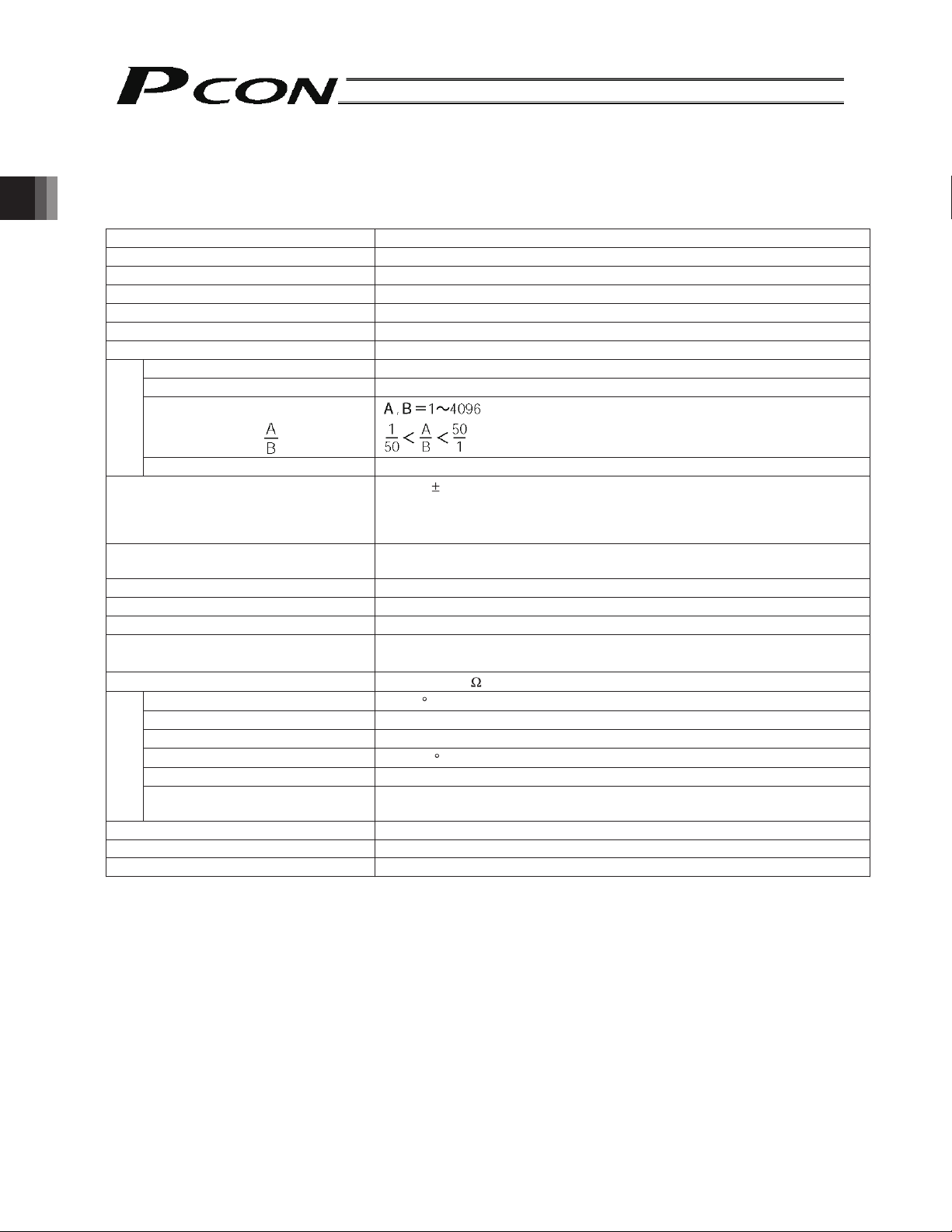
2.1 Basic Specifications
Number of controlled axes 1 axis per unit
Power-supply voltage 24 VDC +10%/-10%
Power-supply current 2 A max.
Control method Field-weakening vector control (patent pending)
2. Specifications
Encoder resolution 800 P/rev
noitpircseDmetinoitacificepS
OP/LP-NOCPledoM
Control mode Position control by pulse train input
Maximum input pulse frequency 60 kpps max. (open collector) / 200 kpps max. (differential)
Command pulse multiplier
mance
(Electronic gear: )
Function/perfor
Positioning complete band 0.1 mm to 999.999 mm (set by parameters)
Power supply for I/O signal I/F
LED indicator
Serial communication RS485, 1 channel (for teaching pendant/dedicated PC software)
Encoder interface Incremental specification conforming to EIA RS-422A/423A
Forced release of electromagnetic brake 24 V is applied to the BK terminal on the power-supply terminal block.
Cable length
Dielectric strength
Surrounding air temperature
Surrounding humidity 85% RH or below (non-condensing)
Surrounding environment Refer to 3.1 Installation Environment
Storage temperature
Storage humidity 90% RH or below (non-condensing)
Environment
Vibration resistance
Protection class Natural air cooling (IP20)
Weight 128 g or below
External dimensions 35 (W) x 120 (H) x 68 (D) mm
24 VDC 10%
Some open collector output has a built-in pull-up resistor, but in such case,
either remove the pull-up resistor or use a port that does not have a pull-up
resistor.
SV (green) --- Whether or not the servo is on / ALM (red) --- Whether or not an
alarm is present or emergency stop is actuated.
Actuator cable: 20 m or shorter
I/O shield cable: 2 m or shorter (open collector) or 10 m or shorter (differential)
500 VDC 10 m
0to40 C
-10 to 65
10 to 57 Hz in all X/Y/Z directions / Single amplitude: 0.035 mm (continuous),
0.075 mm (intermittent)
C
(set by parameters)
16
Page 29

2.2 Name and Function of Each Part of the Controller
PIO connector
Connects the PLC and PIO.
SIO connector
Connects the teaching pendant/PC.
The model of the connected
actuator is indicated here.
Motor connector
Connects the motor cable.
Status indicator LED
SV (Green) --- Indicates whether or not the
servo is on.
ALM (Red) --- Indicates whether or not an
alarm is present or
emergency stop is actuated
Input pulse format
DIF --- Indicates differential line driver
mode.
OC --- Indicates open collector mode.
The I/O signal type is indicated here.
NPN --- Sink type
PNP --- Source type
Encoder connector
Connects the encoder cable.
2. Specifications
Power-supply terminal block
BK
MPI, MPO
24 V Positive side of the 24-VDC input power supply.
0 V Negative side of the 24-VDC input power supply.
EMG-
Model indication of the connected actuator type
The type, ball screw lead and stroke of the actuator are indicated. When connecting the cables, confirm that the
actuator is of the correct specifications.
Example of indication:
Connection terminal for the brake forced-release switch to be used when the actuator is equipped with a
brake. Connect the opposite side of the switch to 24 VDC.
Contacts for cutting off the motor drive power to achieve a safety level of safety category 1.
MPI and MPO connect to the input side and output side of the motor power supply, respectively.
(If these contacts are not used, connect them using a jumper cable. The controller is shipped with MPI and
MPO connected by a jumper cable.)
Connection terminal for the emergency stop circuit (for cutting of motor drive signals).
A common ground is used, so connect the opposite side of the emergency stop switch (or contacts) to the
positive side of the 24-VDC input power supply.
The actuator type is RA4C.
The ball screw lead is 5 mm.
The stroke is 200 mm.
17
Page 30
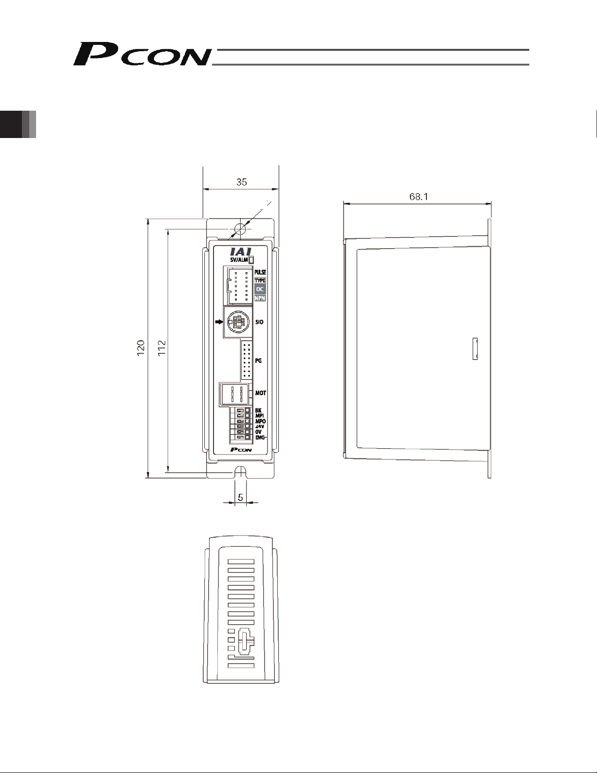
2.3 External Dimensions
An external view and dimensions of this product are shown below.
2. Specifications
∅5
18
Page 31

3. Installation and Wiring
Pay due attention to the environment where the controller is installed.
3.1 Installation Environment
This product is capable for use in the environment of pollution degree 2*1 or equivalent.
*1 Pollution Degree 2 : Environment that may cause non-conductive pollution or transient conductive pollution by frost
(IEC60664-1)
[1] Installation Environment
Do not use this product in the following environment.
• Location where the surrounding air temperature exceeds the range of 0 to 40°C
• Location where condensation occurs due to abrupt temperature changes
• Location where relative humidity exceeds 85%RH
• Location exposed to corrosive gases or combustible gases
• Location exposed to significant amount of dust, salt or iron powder
• Location subject to direct vibration or impact
• Location exposed to direct sunlight
• Location where the product may come in contact with water, oil or chemical droplets
• Environment that blocks the air vent [Refer to 3.3 Noise Elimination Measures and Grounding]
When using the product in any of the locations specified below, provide a sufficient shield.
• Location subject to electrostatic noise
• Location where high electrical or magnetic field is present
• Location with the mains or power lines passing nearby
[2] Storage and Preservation Environment
• Storage and preservation environment follows the installation environment. Especially, when the product is to be left
for a long time, pay special attention to condensed water.
Unless specially specified, moisture absorbency protection is not included in the package when the machine is
delivered. In the case that the machine is to be stored in an environment where dew condensation is anticipated, take
the condensation preventive measures from outside of the entire package, or directly after opening the package.
3. Installation and Wiring
3.2 Supplied Voltage
The controller takes a supplied voltage of 24 VDC ± 10%.
(Maximum power-supply current: 2 A)
19
Page 32

3.3 Noise Elimination Measures and Grounding
The following explains the noise elimination measures that should be taken when using this controller.
(1) Wiring and power connection
[1] Provide dedicated class-D grounding using a grounding wire with a size of 2.0 to 5.5 mm2or larger.
3. Installation and Wiring
Other
Controller
Connect a cable of
the largest possible
size over the shortest
possible distance
Metal
enclosure
[2] Cautions on wiring method
Use a twisted cable to connect the 24-VDC external power supply.
Separate the controller wiring from high-power lines of motive power circuits, etc. (Do not tie them together or place in
the same cable duct.)
If you want to extend the motor or encoder cable beyond the length of the supplied cable, contact IAI.
equip-
ment
Controller
Other
equip-
ment
.nrettapsihtdiovAdooGgnidnuorgD-ssalC
(2) Noise sources and elimination
Noise generates from many sources, but the most common sources of noise you should consider when designing a
system are solenoid valves, magnet switches and relays. Noise generation from these components can be prevented
by the method explained below.
AC solenoid valves, magnet switches, relays
Method --- Install a surge absorber in parallel with the coil
Point
Connect to each coil over the shortest possible wiring distance.
When a surge absorber is installed on the terminal block, etc., its noise
elimination effect will decrease if the distance from the coil is long.
20
Page 33

3.4 Heat Radiation and Installation
Design the control panel size, controller layout and cooling method so that the temperatures around the controller will
always be kept to 40?C or below.
Mount the controller vertically on the wall, as shown below. Since cooling is provided by means of natural convection,
follow this orientation and provide a minimum clearance of 50 mm above and below the controller to allow sufficient
airflows to circulate.
If you are installing multiple controllers side by side, provide a fan on top of the controllers to agitate the airflows as
an effective way to keep the surrounding temperatures constant.
Provide a minimum clearance of 80 mm between the front face of the controller and the wall (cover).
3. Installation and Wiring
Fan
Regardless of whether you are installing one or more controllers, provide sufficient clearances around each controller
to permit easy access for installation and removal of the controller.
At least 50 mm
At least 50 mm
At least 80 mm
Airflow
21
Page 34

3. Installation and Wiring
3.5 External Connection Diagram
An example of standard wiring is shown below.
The wire colors of the robot encoder relay cable are different from those of the standard encoder relay cable. Refer to
3.9.2, “Encoder Relay Cable.”
PCON-PL/PO controller
24-VDC power supply
For teaching pendant/
PC connection
Brake release
switch
Terminal block
for I/O signals
Black
White/Black
Red
White/Red
Green
White/Green
Yellow
White/Yellow
Brown
White/Brown
Blue
White/Blue
Gray
White/Gray
0 V (NPN specification)
24 V (PNP specification)
Load
Load
Load
Load
0 V (NPN specification)
24 V (PNP specification)
Input power
supply
24 VDC
External EMG
switch
I/O shield cable
***
* Affix the round terminal onto the enclosure using a mounting screw.
Motor relay cable
Actuator
Orange
Gray
White
Yellow
Pink
Yellow (Green)
Motor
Encoder relay cable
Yellow
Blue
Orange
Pink
Purple
Green
Brown
Gray
Red
Encoder
Holding brake
22
Page 35

3.6 Wiring the Power Supply
Connect the positive side and negative side of the 24-VDC power supply to the 24-V terminal and N terminal on the
power-supply terminal block, respectively.
Push with a flat-head
screwdriver to open the cable
inlet.
Input power supply
24 VDC
(Max. 2 A per unit)
Use a wire satisfying the following specifications.
Item Specification
Applicable wire Twisted wire: AWG 22 (0.3 mm2) (copper wire)
(Note) Provide proper termination to prevent shorting due to contact with wire offcut.
If the wiring path is long, provide a relay terminal block and connect the original wire to
another wire of a different size.
Input power
supply
Temperature rating of
insulation sheath
Length of bare wire
60°C or above
Power-supply
terminal block
Relay terminal block Power-supply terminal block
Cable inlet
3. Installation and Wiring
_
3.7 Wiring the Brake Forced-release Switch
If the actuator is equipped with a brake, provide a forced-release switch to permit a reset means during startup
adjustment or in case of emergency.
The customer must provide the switch (24 VDC, with a minimum contact capacity of 0.2 A).
Connect one side of the switch to the positive side of the 24-VDC power supply, and connect the other side to the BK
terminal on the power-supply terminal block.
The brake will be released when the switch is closed.
Input power supply
24 VDC
(Max. 2 A per unit)
Danger: If the actuator is oriented vertically, exercise due caution when releasing the brake to prevent the slider/rod
from dropping unexpectedly to pinch your hand or damage the robot hand or work.
Brake forced-release
switch
Power-supply
terminal block
23
Page 36

3.8 Wiring the Emergency Stop Circuit
3.8.1 Cutting Off the Drive Signal (Standard)
Connect one side of the external EMG switch to the positive side of the 24-VDC power supply, and connect the other
side to the BK terminal.
(Note) The EMG switch on the teaching pendant works only on the controller connected to the switch.
3. Installation and Wiring
Teaching pendant
EMG switch
24-VDC input power
supply
(Max. 2 A per unit)
External EMG switch
SIO connector
Power-supply
terminal block
PCON-PL/PO controller
Connection
detection
signal (H)
EMG signal
detection (H)
Time
constant
SIO
connector
connection
detection
circuit
Drive stop
signal (L)
Motor
drive
circuit
24
Power-supply
terminal block (2nd)
Power-supply
terminal block (3rd)
Page 37

If a separate emergency stop circuit is provided to stop the entire system, or when multiple controllers are linked
together and each controller has a different power supply, connect external EMG relay contacts.
24-VDC control
power supply
24-VDC input power
supply
(Max. 2 A per unit)
External EMG
reset switch
External EMG circuit
0 VDC
3. Installation and Wiring
Relay
Power-supply
terminal block (1st)
Power-supply
terminal block (2nd)
24-VDC input power
supply
(Max. 2 A per unit)
24-VDC input power
supply
(Max. 2 A per unit)
Power-supply
terminal block (3rd)
25
Page 38

3.8.2 Cutting Off the Motor Drive Power
If the motor drive power must be cut off in order to meet the required safety category of the entire system, connect
external EMG relay contacts between the MPI terminal and MPO terminal.
Also connect the 24-V controller power supply to the EMG terminal.
(Note) The EMG switch on the teaching pendant cuts off the motor driver signal. It does not cut off the motor drive
power.
3. Installation and Wiring
24-VDC control
power supply
24-VDC input power
supply
(Max. 2 A per unit)
External EMG
reset switch
External EMG circuit
0 VDC
Relay
Power-supply
terminal block (1st)
For driving the motor
These lines are
shorted internally.
Power-supply
terminal block (2nd)
26
24-VDC input power
supply
(Max. 2 A per unit)
24-VDC input power
supply
(Max. 2 A per unit)
For driving the motor
These lines are
shorted internally.
Power-supply
terminal block (3rd)
For driving the motor
These lines are
shorted internally.
Page 39

3.9 Connecting the Actuator
3.9.1 Motor Relay Cable
• Connect the motor relay cable to the MOT connector.
Signal table of controller-end connector (CN2)
Pin No. Signal Wire color Description
A1
A
A2 VMM Gray Motor power line
A3
B
B1 A Yellow Motor drive line (phase +A)
B2 VMM Pink Motor power line
B3 B Yellow (Green) Motor drive line (phase +B)
Controller end Actuator end
CN2 pin layout CN1 pin layout
Orange Motor drive line (phase -A)
White Motor drive line (phase -B)
3. Installation and Wiring
Cable color
Orange
Gray
White
Yellow
Pink
Yellow (Green)
Housing: 1-1318119-3 (AMP)
Receptacle contact: 1318107-1
Signal
abbreviation
Pin No. Cable color
Pin No.
Housing: SLP-06V (J.S.T. Mfg.)
Socket contact: BSF-21T-P1.4
Signal
abbreviation
Yellow
Gray
Orange
Yellow (Green)
Pink
White
27
Page 40

3. Installation and Wiring
3.9.2 Encoder Relay Cable
• Connect the encoder relay cable to the PG connector.
Signal table of controller-end connector (CN2)
Pin No. Signal abbreviation Description
1 F.G Shielded wire
2 - (Not used)
3 - (Not used)
4 - (Not used)
5 GND
6 5V
7 VPS Encoder control signal output
8 - (Reserved)
9
ENB
10 ENB
11
ENA
12 ENA
13 BK - Brake power –
14 BK + Brake power +
15 LS 16 LS +
Controller end Actuator end
CN2 pin layout CN1 pin layout
Encoder power output
Encoder differential signal phase-B input
Encoder differential signal phase-A input
Home check sensor
Cable color
Robot cable Standard cable
Purple
White (vs.Purple)
Blue
White (vs. Blue)
Yellow
White (vs.Yellow)
Green
Red
White (vs. Red)
Drain
Housing: PHDR-16VS (J.S.T. Mfg.)
Contact: SPHD-001T-P0.5
Red
Gray
Brown
Green
Purple
Pink
Yellow
Orange
Blue
Drain
Signal
abbreviation
(Reserved)
Standard cable
Robot cable
Pin No.
Pin No.
Retainer: XMS-09V
Signal
abbreviation
Housing: XMP-18V (J.S.T. Mfg.)
Contact: BXA-001T-P0.6
Cable color
Standard cable Robot cable
Brown
Green
Purple
Pink
Blue
Orange
Yellow
Red
Gray
Drain
Blue
White (vs. Blue)
Yellow
White (vs. Yellow)
White (vs. Red)
Red
Green
Purple
White (vs. Purple)
Drain
28
Page 41

3.10 Connecting the I/O Shield Cable
Cable model: CB-PACPU-PIO***
(Note: *** indicates the cable length. (Example) 2 m: 020)
No connector
Shield cable
Housing
Contact
Round terminal: 0.5-5 (JST)
Pin No. Color Name Remarks
1 Black External 24 V
2 White/Black External ground
If the controller is used in the open collector mode, also use this
pin for the COMMON signal for command pulses.
3 Red SON Servo-on signal
4 White/Red TL Torque-limit selection signal
5 Green HOME Homing signal
6 White/Green RES/DCLR Reset signal/deviation-counter clear signal
7 Yellow SV Servo-on output
8 White/Yellow INP/TLR Positioning complete signal/torque limit signal
9 Brown HEND Homing complete signal
10 White/Brown *ALM Alarm signal
11 Blue Command pulse (/PP)
12 White/Blue Command pulse (PP) Not connected if the controller is used in the open collector mode.
13 Gray Command pulse (/NP)
14 White/Gray Command pulse (NP) Not connected if the controller is used in the open collector mode.
- - FG Shield (connected to the enclosure)
3. Installation and Wiring
29
Page 42

3.11 Connecting the Communication Cable
Connect the communication cable to the SIO connector.
RS485 conversion adapter end Controller end
Pin layout of cable-end connector
3. Installation and Wiring
Cable color
Brown
Yellow
Red
Orange
Blue
Green
Shorting wire UL1004AWG28 (Black)
Not connected to the shield.
Signal
abbreviation
Pin No.
Pin No.
Signal
abbreviation
Cable color
Yellow
Orange
Brown/Green
Black
Red/Blue
Black
Shield
30
Page 43

4. Operation Using I/O Signals
This chapter explains the wire connections and operation timings you should know in order to perform positioning
operation using a PLC with I/O signals. Two PIO patterns are available for you to choose from in accordance with your
specific application.
PIO pattern Setting (User Parameter No. 25)
Standard type (factory setting) 0
Push type 1
4.1 Interface Circuit
The standard interface circuit conforms to the NPN specification, but the PNP specification type is also available as an
option.
To simplify wiring, a common power line is used for both the NPN specification and PNP specification. Accordingly you
need not reverse the power connections when using the PNP specification.
4.1.1 External Input Specifications
Item Specification
Number of input points 4 points
Input voltage
Input current 5 mA per circuit
Operating voltage
Leak current Max. 1 mA per point
Insulation method Photocoupler
24 VDC ± 10%
ON voltage: Min. 18 V (3.5 mA)
OFF voltage: Max. 6 V (1 mA)
4. Operation Using I/O Signals
Internal circuit configuration
[NPN specification]
+24-V external
power supply
[PNP specification]
+24-V external
power supply
Controller
Internal circuit
Each
input
Controller
Internal circuit
Each
input
31
Page 44

4.1.2 External Output Specifications
Item Specification
Number of output points 4 points
Rated load voltage 24 VDC
Maximum current 50 mA per point
Residual voltage Max. 2 V
Insulation method Photocoupler
Internal circuit configuration
[NPN specification]
Controller
Load
4. Operation Using I/O Signals
[PNP specification]
Internal circuit
Internal circuit
Each output
Load
+24-V external
power supply
Controller
+24-V external
power supply
Load
Each output
Load
32
Page 45

4.1.3 Command Pulse Train Input Specifications
[Input using a differential line driver]
Applicable line driver: 26C31 or equivalent
Mounting plate
Note Always connect the shield of the twisted pair cable joined to the connector, to the mounting plate.
[Input using an open collector]
4. Operation Using I/O Signals
Mounting plate
Note 1 Always connect the shield of the twisted pair cable joined to the connector, to the mounting plate.
Note 2 Some open collector outputs have built-in pull-up resistors, but in such case, either remove the pull-up
resistor or use a port that does not have a pull-up resistor.
(Provide 24 V for pulse train input.)
33
Page 46

4.1.4 Recognition of Input Signals
r
The input signals of this controller have an input time constant to prevent malfunction due to chattering, noise, etc.
Each input signal is switched when the new signal state has continued for at least 6 msec.
In other words, when the input is switched from OFF to ON, the controller will recognize that the input signal is ON after
6 msec. The same applies when the input is switched from ON to OFF.
* Excluding command pulse input (PP•/PP, NP•/NP).
Recognition by the controlle
4. Operation Using I/O Signals
Input signal
Not recognized
Not recognized
34
Page 47

4.1.5 Notes on the ROBO Gripper
(1) Finger Operation
[1] Definition of position
With the two-finger type, the stroke specification indicates the total sum of travels by both fingers. In other
words, the travel by one finger is one-half this stroke.
A position is specified as a travel by one finger from the home position toward the closing direction.
Therefore, the maximum command value is 5 mm for the GRS type, and 7 mm for the GRM type.
[2] Definition of speed and acceleration
The command value applies to one finger.
With the two-finger type, the relative speed and acceleration are double the command values, respectively.
[3] Gripper operation mode
In applications where the work is to be gripped, be sure to use the “push-motion mode.”
[Diagram of gripping force and current-limiting value]
4. Operation Using I/O Signals
Gripping force (N)
Gripping force P (N)
Gripping force P (N)
Gripping force (N)
Current-limiting value (%) Current-limiting value (%)
Gripping force P (N)
Current-limiting value (%) Current-limiting value (%)
Gripping force P (N)
Current-limiting value (%) Current-limiting value (%)
35
Page 48

(2) Removing the gripped work
The ROBO Gripper is structured in such a way that even when the controller power is cut off, the work gripping force
will still be maintained by a self-lock mechanism.
If you must remove the gripped work while the power is cut off, turn the open/close screw or remove one of the finger
attachments to release the work.
[Two-finger type]
Turn the open/close screw or remove one of the finger attachments.
Finger attachment
Open/close screw
Turn counterclockwise using
a flat-head screwdriver.
4. Operation Using I/O Signals
[Three-finger type]
Remove one of the finger attachments.
Finger attachment
OPEN
Opening
direction
Affixing bolt
Affixing bolt
36
Page 49

4.2 Standard Type
Choose the PIO pattern of this type if you wish to perform position control using pulse train input from a PLC.
Set User Parameter No. 25 (PIO pattern selection) to “0.” (This parameter has been set to the “standard type” prior to
the shipment).
4.2.1 Explanation of I/O Signals
Pin No. Signal Name Remarks
1 24 V External 24 V
If the controller is used in the open collector mode, also use this pin for the
2 0 V External ground
3 IN0 SON Servo-on signal
4 IN1 TL Torque-limit selection signal
5 IN2 HOME Homing signal
6 IN3 RES Reset signal
7 OUT0 SV Servo-on output
8 OUT1 INP Positioning complete signal
9 OUT2 HEND Homing complete signal
10 OUT3 *ALM Alarm signal
11 /PP Command pulse
12 PP Command pulse Not connected if the controller is used in the open collector mode.
13 /NP Command pulse
14 NP Command pulse Not connected if the controller is used in the open collector mode.
COMMON signal for command pulses as well as the 0V signal for the
controller’s control power.
4. Operation Using I/O Signals
Servo-on Command Input (SON)
The servo remains on while this signal is ON.
The actuator can be operated while the SON signal is ON.
While this signal is OFF, the actuator does not operate even when the controller power is supplied.
If the SON signal is turned OFF while the actuator is operating, the actuator will decelerate at the forced-stop torque
until it stops. After the actuator stops, the servo will turn off and the motor will enter a free-run state.
At this time, the function specified by the applicable parameter (electromagnetic brake) becomes active (provided
that the actuator is equipped with a brake).
When the servo turns off, the deviation counter will be cleared if User Parameter No. 58 (Clear deviation at servo
off/alarm stop) is set to “Enable.”
Reset Signal Input (RES)
This signal resets the alarms currently detected by the controller.
You can turn the RES signal ON to reset the alarms currently detected by the controller.
Caution: This signal cannot reset cold-start level alarms. Identify the cause of each alarm and remove the cause
before restarting the controller.
37
Page 50

Torque-limit Selection Signal (TL)
This signal limits the motor torque.
While this signal is ON, the actuator thrust (motor torque) is limited to the torque set in User Parameter No. 57
(Torque limit).
Caution: Excessive deviation (standing pulses) may generate while torque is limited (while the TL signal is
ON) (for example, when the actuator receives load and is prevented from moving just like in
push-motion operation).
If the TL signal is turned OFF in this condition, the controller will instantly start controlling the
actuator at the maximum torque and the actuator may move suddenly or run out of control.
This signal can be disabled using User Parameter No. 61 (Torque-limit command input). Disable the TL signal if it is
not used.
Homing Signal (HOME)
This command signal is used to perform homing automatically.
The homing command is processed at the leading edge (ON edge) of the HOME signal to cause the actuator to
return to its home automatically.
When the homing is completed, the HEND (homing complete) output signal turns ON.
4. Operation Using I/O Signals
Program the host controller (PLC) so that its current-value register will be reset to the home (“0” will be input to the
register) by the current-value preset function, etc., upon turning ON of the HOME signal.
* This signal is always enabled as long as the servo is on.
* Even after homing has been performed once, homing can be performed again by turning the HOME signal ON.
Caution: The HOME signal is given priority over pulse train commands. Even while the actuator is moving
under a pulse train command, it will start moving to the home once the HOME signal is turned
ON.
The HOME signal is processed only at its leading edge (ON edge).
If the SON signal turns OFF or an alarm is detected during homing, the homing operation will
stop. If the servo turns off, the homing command will be cancelled even if the HOME signal is
still ON. To perform homing again, turn the HOME signal OFF, and then turn it back ON.
The actuator can be operated without using this function. If this function is not used, however, all
management actions over position data will be left to the host controller.
In this case, take necessary measures to prevent an over-stroke error, such as not sending pulse
commands exceeding the effective stroke, or providing external limit switches or other devices for
detecting stroke ends to forcibly stop the actuator upon detection of a stroke end.
38
Page 51

Command Pulse Input
Command pulses can be input in the open collector mode (MAX 60 kpps) or differential line driver mode (MAX 200
kpps).
You can select a desired input pattern of command pulses from 90° phase-difference (phase-A/B x4) signal, pulse
train + forward/reverse signal, and forward pulse/reverse pulse. The positive logic or negative logic can be selected
for each of these patterns.
Caution: The actuator moves in the negative direction (the motor runs in the forward direction) when
forward pulses are input, and moves in the positive direction (the motor runs in the reverse
direction) when reverse pulses are input. (These directions are reversed if the actuator is of motor
reversing type.)
When determining the forward/reverse directions, pay attention to the host controller setting as
well as the PP•/PP and NP•/NP connection.
For actuator accelerations/decelerations, set values not exceeding the rated
acceleration/deceleration of the actuator. (The rated acceleration/deceleration of each actuator is
specified in the actuator’s catalog.)
* The motor direction is determined based on CCW representing the forward direction when viewed
from the load-end of the shaft.
You can set one of six command pulse patterns in the command-pulse input mode.
4. Operation Using I/O Signals
Command-pulse
input pattern
Forward pulse train
Reverse pulse train
Forward pulse trains indicate motor revolutions in the positive direction, while reverse pulse trains indicate
motor revolutions in the reverse direction.
Pulse train
Sign
Command pulses indicate motor revolutions, while the sign of the command indicates the rotating direction.
Negative logic Positive logic
Phase-A/B pulse train
Phase-A/B x4 pulses of 90° phase difference indicate both revolutions and rotating direction.
Forward pulse train
Reverse pulse train
Input terminal Forward Reverse
Pulse train
Sign
Phase-A/B pulse train
39
Page 52

Positioning Complete Signal (INP)
This signal turns ON when the deviation in the deviation counter (standing pulses) is within the positioning band. It
remains OFF while the servo is off.
Caution: This signal turns ON when the servo is turned on (to perform positioning at the present position).
This signal turns ON simply due to accumulation of deviation (standing pulses). Therefore,
The INP signal is recognized even when the TL signal is ON.
Homing Complete Signal (HEND)
This signal turns ON after homing has completed and the coordinate system has been established.
It turns ON upon completion of homing initiated by the HOME signal or a command from the teaching pendant or
PC software.
This signal turns OFF once the servo turns off. Perform homing again after the servo has turned off.
Caution: The software stroke limits set by the corresponding actuator parameters are effective only
4. Operation Using I/O Signals
The actuator can be operated without using this function. In this case, however, take
setting an excessively wide positioning band in the applicable position control parameter will
cause the INP signal to turn ON once the actuator enters the positioning band during
low-speed operation (before positioning is completed).
while this signal is ON.
necessary measures, such as not sending pulse commands exceeding the effective stroke, or
providing external limit switches for detecting stroke ends to forcibly stop the actuator upon
detection of a stroke end.
Servo-on Output Signal (SV)
When the SON (servo-on) signal turns ON, the servo turns on. As the controller subsequently enters a ready state
(where it can accept pulse train input) (the condition where the controller can accept pulse train input = pulse mode),
this signal turns ON.
This signal turns OFF when the servo is turned off upon turning OFF of the SON signal.
This signal is linked to the LED (green light) on the front panel of the controller.
40
Page 53

Alarm Signal (*ALM)
This signal turns OFF when the controller’s protective circuit (function) has actuated following an alarm detection
and the basic cutoff procedure has been implemented as a result.
The signal will turn ON if the RES (reset) signal is turned ON after the cause of the alarm has been removed
(except when the alarm relates to a cold-start level error).
When an alarm is detected, a red LED light will illuminate on the front panel of the controller. A green LED remains
on while the controller is operating normally.
Caution: Identify the cause of each alarm and remove the cause before restarting the controller.
You can check alarm codes using the teaching pendant or PC software. The controller can
store data of up to 16 most recent alarms. This alarm history data will be retained even after
the power is cut off.
Each alarm record is displayed with the time it was generated, so you can check which alarm
occurred when.
For details on alarm history, refer to 6.3, “Alarms, Causes and Actions.”
4. Operation Using I/O Signals
41
Page 54

4.2.2 Setting Parameters Required for Operation
The following parameters must always be set prior to every operation.
(These parameters are all you need to set to perform operations that only involve positioning.)
(1) Electronic gear
User Parameter Nos. 65 and 66 (Electronic gear numerator and denominator)
Name Symbol Unit Input range Default (reference)
Electronic gear numerator CNUM - 1 to 4096 200
Electronic gear denominator CDEN - 1 to 4096 15
These parameters are used to determine the unit travel distance of the actuator per one pulse in input command
pulse train.
Unit travel distance of linear-motion axis = Minimum travel unit (1, 0.1, 0.01 mm, etc.)/pulse
Unit travel distance of rotational axis = Minimum travel unit (1, 0.1, 0.01 deg, etc.)/pulse
Calculation Formula for Electronic Gear
Linear-motion axis
4. Operation Using I/O Signals
Electronic gear numerator (CNUM) Encoder pulses (Pulse/rev)
Electronic gear denominator
(CDEN)
Rotational axis
Electronic gear numerator (CNUM) Encoder pulses (Pulse/rev)
Electronic gear denominator
(CDEN)
Reference
The actuator speed is calculated as follows:
Speed = Unit travel distance x Input pulse frequency (Hz)
Take note that if the unit travel distance is too small, the actuator may not be able to reach the maximum speed.
Table of encoder pulses and lead lengths for different models
Actuator type(s)
SA5C/SA6C/SA7C/SS7C/SS8C
SA5R/SA6R/SA7R/SS7R/SS8R
RA2C/RA3C/RA4C/RA6C
RGS4C/RGS6C/RGD3C/RGD4C/RGD6C
BA6/BA6U/BA7/BA7U
GRS
GRM
GR3LS/GR3LM
GR3SS
GR3SM
RTB (Gear ratio 1/20)/ RTC (Gear ratio 1/20)
RTB (Gear ratio 1/30)/ RTC (Gear ratio 1/30)
=
Ball screw lead length (mm/rev)
=
360 (deg/rev) x Gear ratio of rotational axis
Encoder pulses
㸦Pulse/rev㸧
800
800
800 1
800 1.1
800 12
800 2.5
800 3
800 18
800 12
x Unit travel distance (mm/Pulse)
x Unit travel distance (deg/Pulse)
Lead length
Check the lead length shown on the
controller front panel
54
42
Page 55

Calculation Example
Operate an actuator with a ball screw lead of 6 mm equipped with an encoder of 800 pulses/rev, at a unit travel
distance to 0.1 mm (1/10).
* Encoder pulses are 800 pulses/rev for all RCP2 models.
Electronic gear numerator (CNUM) Encoder pulses (Pulse/rev)
Electronic gear denominator
(CDEN)
=
Ball screw lead length (mm/rev)
x Unit travel distance (mm/Pulse)
The electronic gear numerator (CNUM) and electronic gear denominator (CDEN) are 40 and 3, respectively. Based
on these settings, the travel distance per one pulse in input command pulse train is calculated as 0.1 mm.
Caution:
Set both the electronic gear numerator (CNUM) and electronic gear denominator (CDEN) as integers not
exceeding 4,096, by reducing them as much as possible with a common divisor.
Also, CNUM and CDEN must satisfy the relational expression specified below.
31
≥
2
31
≥
2
Stroke length (mm)
Ball screw lead length (mm/rev)
Stroke length (mm)
Ball screw lead length (mm/rev)
x Encoder pulses (Pulse) x (CNUM)
x Encoder pulses (Pulse) x (CDEM)
4. Operation Using I/O Signals
Do not set a minimum travel unit smaller than the encoder resolution.
Encoder resolution for linear-motion axis (mm/Pulse) =
Encoder resolution for rotational axis (deg/Pulse) =
Ball screw lead length (mm/rev)
Encoder pulses (Pulse/rev)
300 (deg/rev) x Gear ratio of rotational axis
Encoder pulses (Pulse/rev)
The actuator will not move unless enough command pulses accumulate to reach or exceed the encoder resolution.
43
Page 56

(2) Command Pulse Mode
User Parameter No. 63 (Command-pulse input mode)
Name Symbol Unit Input range Default (reference)
Command-pulse input mode MOD - 0 to 2 1
Set a pulse-train input pattern for command pulse input (PP•/PP, NP•/NP).
* The setting of positive logic or negative logic is explained in (3), “Input Polarity in the Command Pulse Mode.”
Command-pulse
input pattern
Forward pulse train
Reverse pulse train
Forward pulse trains indicate motor revolutions in the positive direction, while reverse pulse trains indicate
motor revolutions in the reverse direction.
Pulse train
Sign
4. Operation Using I/O Signals
Command pulses indicate motor revolutions, while the sign of the command indicates the rotating direction.
Negative logic Positive logic
Phase-A/B pulse train
Phase-A/B x4 pulses of 90° phase difference indicate both revolutions and rotating direction.
Forward pulse train
Reverse pulse train
Input terminal Forward Reverse Setting
Pulse train
Sign
Phase-A/B pulse train
(3) Input Polarity in the Command Pulse Mode
User Parameter No. 64 (Polarity in command-pulse input mode)
Name Symbol Unit Input range Default (reference)
Polarity in command-pulse input mode POLE - 0 to 1 0
Setting
Positive logic: 0
Negative logic: 1
44
Page 57

Warning: Since the drive motor is a pulse motor, the excited phase is detected when the servo is turned on for
the first time after turning on the power.
Therefore, one condition for the servo to turn on is that the actuator can move once the servo is turned
on.
If the slider or rod is contacting a mechanical end or the work is contacting any peripheral equipment,
the excited phase may not be detected correctly and an erroneous movement or excitation detection
error may occur.
In this case, move the actuator manually to an appropriate position before turning the servo on.
If the actuator is equipped with a brake, the brake must be forcibly released by turning on the brake
release switch. At this time, be careful not to pinch your hand or damage the robot hand or work by the
slider/rod, as the slider/rod may drop unexpectedly by its dead weight. If the actuator cannot be moved
by hand, you can change Parameter No. 28 (Direction of excited phase signal detection). Before
changing this parameter, contact IAI.
4. Operation Using I/O Signals
45
Page 58

A
(Note1:Next
)
4.2.3 Timings after Power On
Steps from Initial Startup to Actuator Adjustment
[1] Confirm that the slider or rod is not contacting a mechanical end or that the work is not contacting any
peripheral equipment.
[2] Cancel the emergency stop or connect the motor drive power.
[3] Supply the 24-VDC I/O power: PIO connector pins 1 and 2.
[4] Supply the 24-VDC controller power: 24-V and 0-V terminals on the power-supply terminal block.
[5] Set the minimum required parameters. Refer to 4.2.2, “Setting Parameters Required for Operation.”
Reference To temporarily disable the servo-on input because the PLC is not yet ready to accept the input,
change the value of Parameter No. 21 (Servo-on input disable selection) to “1.”
[6] Input a servo-on signal from the PLC (if the servo-on input is enabled).
[7] Input a homing signal from the PLC.
[8] Input position command pulses from the PLC.
Safety circuit status
4. Operation Using I/O Signals
Supply of 24-VDC I/O
power
Supply of 24-VDC
controller power
Servo-on input (SON)
SV lamp (front panel)
Homing input
(HOME)
Homing complete
output (HEND)
Emergency stop cancelled
n orange light
comes on for 2
seconds, and
then turns off.
T
1
MIn. 170 msec
Green
page
Min. 6 msec
Command pulse input
46
Page 59

* If Parameter No. 21 (Servo-on input disable selection) is set to “1,” a servo-on signal need not be input.
(Note1)
Caution: In the “Emergency stop actuated → Turn on the power → Servo-on input → Cancel the
emergency stop” sequence, the servo will turn on up to T
(Note 1)
sec after the emergency stop is
1
cancelled.
Servo-on input
Emergency stop cancelled
T
1
(Note 1) T1: Excited-pole detection time = 0.2 to 12 sec
Normally the detection of excited pole completes in approx. 0.2 sec, although the exact time varies
from one actuator to another due to individual differences and also depending on the load condition. If
the detection of excited pole has failed, the excited-pole detection operation will be continued for up to
12 sec.
4. Operation Using I/O Signals
47
Page 60

4.3 Push Type
Use the PIO pattern of this type if you wish to perform position control and push-motion operation using pulse train
input from a PLC.
Set User Parameter No. 25 (PIO pattern selection) to “1.”
4.3.1 Explanation of I/O Signals
Pin No. Signal Name Remarks
1 24 V External 24 V
2 0 V External ground
3 IN0 SON Servo-on signal
4 IN1 TL Torque-limit selection signal
5 IN2 HOME Homing signal
6 IN3 RES Reset signal/deviation-counter clear signal
7 OUT0 SV Servo-on output
8 OUT1 INP Positioning complete signal/torque limit signal
9 OUT2 HEND Homing complete signal
4. Operation Using I/O Signals
10 OUT3 *ALM Alarm signal
11 /PP Command pulse
12 PP Command pulse
13 /NP Command pulse
14 NP Command pulse
If the controller is used in the open collector mode, also use this
pin for the COMMON signal for command pulses as well as the
0V signal for the controller’s control power.
Not connected if the controller is used in the open collector
mode.
Not connected if the controller is used in the open collector
mode.
Servo-on Command Input (SON)
The servo remains on while this signal is ON.
The actuator can be operated while the SON signal is ON.
While this signal is OFF, the actuator does not operate even when the controller power is supplied.
If the SON signal is turned OFF while the actuator is operating, the actuator will decelerate at the forced-stop torque
until it stops. After the actuator stops, the servo will turn off and the motor will enter a free-run state.
If the actuator is equipped with a brake, the function specified by the applicable parameter (electromagnetic brake)
is activated.
When the servo turns off, the deviation counter will be cleared (if User Parameter No. 58 Clear deviation at servo
off/alarm stop is set to “Enable.”)
Reset Signal Input (RES)
This signal resets the alarms currently detected by the controller.
You can turn the RES signal ON to reset the alarms currently detected by the controller.
Caution: This signal cannot reset cold-start level alarms. Identify the cause of each alarm and remove the
cause before restarting the controller.
Deviation-counter Clear Signal (DCLR)
While the TL signal is ON, the RES signal functions as the deviation-counter clear signal (DCLR).
The deviation counter is cleared continuously while this signal is ON.
Upon completion of push-motion operation, you can clear the deviation counter by inputting this signal.
48
Page 61

Torque-limit Selection Signal (TL)
This signal limits the motor torque.
While this signal is ON, the actuator thrust (motor torque) is limited to the torque set in User Parameter No. 57
(Torque limit).
Caution: Do not turn the TL signal OFF while it is ON.
If the TL signal is turned OFF in this condition, the controller will instantly start controlling the
actuator at the maximum torque and the actuator may move suddenly or run out of control.
This signal can be disabled using User Parameter No. 61 (Torque-limit command input). Disable the TL signal if it is
not used.
Homing Signal (HOME)
This command signal is used to perform homing automatically.
When the HOME signal is turned ON, the command will be processed at the leading edge (ON edge) of the signal
and the actuator will return to its home automatically.
When the homing is completed, the HEND (homing complete) output signal turns ON.
Program the host controller (PLC) so that its current-value register will be reset to the home (“0” will be input to the
register) by the current-value preset function, etc., upon turning ON of the HOME signal.
* This signal is always enabled as long as the servo is on.
* Even after homing has been performed once, homing can be performed again by turning the HOME signal ON.
Caution: The HOME signal is given priority over pulse train commands. Even while the actuator is moving
under a pulse train command, it will start moving to the home once the HOME signal is turned
ON.
The HOME signal is processed only at its leading edge (ON edge).
If the SON signal turns OFF or an alarm is detected during homing, the homing operation will
stop. If the servo turns OFF , the homing command will be cancelled even if the HOME signal is
still ON. To perform homing again, turn the HOME signal OFF, and then turn it back ON.
The actuator can be operated without using this function. If this function is not used, however, all
management actions over position data will be left to the host controller.
In this case, take necessary measures to prevent an over-stroke error, such as not sending pulse
commands exceeding the effective stroke, or providing external limit switches or other devices for
detecting stroke ends to forcibly stop the actuator upon detection of a stroke end.
4. Operation Using I/O Signals
49
Page 62

Command Pulse Input
Command pulses can be input in the open collector mode (MAX 60 kpps) or differential line driver mode (MAX 200
kpps).
You can select a desired input pattern of command pulses from 90° phase-difference (phase-A/B x4) signal, pulse
train + forward/reverse signal, and forward pulse/reverse pulse. The positive logic or negative logic can be selected
for each of these patterns.
Caution: The actuator moves in the negative direction (the motor runs in the forward direction) when
When determining the forward/reverse directions, pay attention to the host controller setting as
For actuator accelerations/decelerations, set values not exceeding the rated
* The motor direction is determined based on CCW representing the forward direction when viewed
from the load-end of the shaft.
You can set one of six command pulse patterns in the command-pulse input mode.
Command-pulse
input pattern
4. Operation Using I/O Signals
Forward pulse train
Reverse pulse train
forward pulses are input, and moves in the positive direction (the motor runs in the reverse
direction) when reverse pulses are input. (These directions are reversed if the actuator is of motor
reversing type.)
well as the PP•/PP and NP•/NP connection.
acceleration/deceleration of the actuator. (The rated acceleration/deceleration of each actuator is
specified in the actuator’s catalog.)
Input terminal Forward Reverse
Forward pulse trains indicate motor revolutions in the positive direction, while reverse pulse trains indicate
motor revolutions in the reverse direction.
Pulse train
Sign
Command pulses indicate motor revolutions, while the sign of the command indicates the rotating direction.
Negative logic Positive logic
Phase-A/B pulse train
Phase-A/B x4 pulses of 90° phase difference indicate both revolutions and rotating direction.
Forward pulse train
Reverse pulse train
Pulse train
Sign
50
Phase-A/B pulse train
Page 63

Positioning Complete Signal (INP)
This signal turns ON when the deviation in the deviation counter (standing pulses) is within the positioning band. It
remains OFF while the servo is off.
Caution: This signal turns ON when the servo is turned on (to perform positioning at the present position).
This signal turns ON simply due to accumulation of deviation (standing pulses). Therefore,
setting an excessively wide positioning band in the applicable position control parameter will
cause the INP signal to turn ON once the actuator enters the positioning band during
low-speed operation (before positioning is completed).
Torque Limiting Signal (TLR)
This signal turns ON when the specified torque limit is reached in the torque limiting mode.
While the TL (torque-limit selection) signal is ON, this signal will turn ON if the actuator thrust (motor torque)
reaches the torque limit set by the torque limit parameter.
This signal will turn OFF once the motor torque drops to below the specified limit.
Homing Complete Signal (HEND)
This signal turns ON after homing has completed and the coordinate system has been established.
It turns ON upon completion of homing initiated by the HOME signal or a command from the teaching pendant or
PC software.
This signal turns OFF once the servo turns off. Perform homing again after the servo has turned off.
Caution: The software stroke limits set by the corresponding actuator parameters are effective only
while this signal is ON.
The actuator can be operated without using this function. In this case, however, take
necessary measures, such as not sending pulse commands exceeding the effective stroke, or
providing external limit switches for detecting stroke ends to forcibly stop the actuator upon
detection of a stroke end.
4. Operation Using I/O Signals
Servo-on Output Signal (SV)
When the SON (servo-on) signal turns ON, the servo turns on. As the controller subsequently enters a ready state
(where it can accept pulse train input) (the condition where the controller can accept pulse train input = pulse mode),
this signal turns ON.
This signal turns OFF when the servo is turned off upon turning OFF of the SON signal.
This signal is linked to the LED (green light) on the front panel of the controller.
51
Page 64

Alarm Signal (*ALM)
This signal turns OFF when the controller’s protective circuit (function) has actuated following an alarm detection
and the basic cutoff procedure has been implemented as a result.
The signal will turn ON if the RES (reset) signal is turned ON after the cause of the alarm has been removed
(except when the alarm relates to a cold-start level error).
When an alarm is detected, a red LED light will illuminate on the front panel of the controller. A green LED remains
on while the controller is operating normally.
Caution: Identify the cause of each alarm and remove the cause before restarting the controller.
You can check alarm codes using the teaching pendant or PC software. The controller can
Each alarm record is displayed with the time it was generated, so you can check which alarm
For details on alarm history, refer to 6.3, “Alarms, Causes and Actions.”
4. Operation Using I/O Signals
store data of up to 16 most recent alarms. This alarm history data will be retained even after
the power is cut off.
occurred when.
52
Page 65

4.3.2 Setting Parameters Required for Operation
The following parameters must always be set prior to every operation.
(These parameters are all you need to set to perform operations that only involve positioning.)
(1) Electronic gear
User Parameter Nos. 65 and 66 (Electronic gear numerator and denominator)
Name Symbol Unit Input range Default (reference)
Electronic gear numerator CNUM - 1 to 4096 200
Electronic gear denominator CDEN - 1 to 4096 15
These parameters are used to determine the unit travel distance of the actuator per one pulse in input command
pulse train.
Unit travel distance of linear-motion axis = Minimum travel unit (1, 0.1, 0.01 mm, etc.)/pulse
Unit travel distance of rotational axis = Minimum travel unit (1, 0.1, 0.01 deg, etc.)/pulse
Calculation Formula for Electronic Gear
Linear-motion axis
Electronic gear numerator (CNUM) Encoder pulses (Pulse/rev)
Electronic gear denominator
(CDEN)
Rotational axis
Electronic gear numerator (CNUM) Encoder pulses (Pulse/rev)
Electronic gear denominator
(CDEN)
Reference
The actuator speed is calculated as follows:
Speed = Unit travel distance x Input pulse frequency (Hz)
Take note that if the unit travel distance is too small, the actuator may not be able to reach the maximum speed.
=
Ball screw lead length (mm/rev)
=
360 (deg/rev) x Gear ratio of rotational axis
x Unit travel distance (mm/Pulse)
x Unit travel distance (deg/Pulse)
4. Operation Using I/O Signals
Table of encoder pulses and lead lengths for different models
Actuator type(s)
Encoder pulses
㸦Pulse/rev㸧
SA5C/SA6C/SA7C/SS7C/SS8C
SA5R/SA6R/SA7R/SS7R/SS8R
RA2C/RA3C/RA4C/RA6C
RGS4C/RGS6C/RGD3C/RGD4C/RGD6C
BA6/BA6U/BA7/BA7U
GRS
GRM
GR3LS/GR3LM
GR3SS
GR3SM
RTB (Gear ratio 1/20)/ RTC (Gear ratio 1/20)
RTB (Gear ratio 1/30)/ RTC (Gear ratio 1/30)
Lead length
Check the lead length shown on the
800
800
800 1
800 1.1
800 12
800 2.5
800 3
800 18
800 12
controller front panel
54
53
Page 66

Calculation Example
Operate an actuator with a ball screw lead of 6 mm equipped with an encoder of 800 pulses/rev, at a unit travel
distance to 0.1 mm (1/10).
* Encoder pulses are 800 pulses/rev for all RCP2 models.
Electronic gear numerator (CNUM) Encoder pulses (Pulse/rev)
Electronic gear denominator
(CDEN)
The electronic gear numerator (CNUM) and electronic gear denominator (CDEN) are 40 and 3, respectively. Based
on these settings, the travel distance per one pulse in input command pulse train is calculated as 0.1 mm.
Caution:
Set both the electronic gear numerator (CNUM) and electronic gear denominator (CDEN) as integers not
4. Operation Using I/O Signals
exceeding 4,096, by reducing them as much as possible with a common divisor.
Also, CNUM and CDEN must satisfy the relational expression specified below.
31
2
≥
31
≥
2
=
Ball screw lead length (mm/rev)
Stroke length (mm)
Ball screw lead length (mm/rev)
Stroke length (mm)
Ball screw lead length (mm/rev)
x Unit travel distance (mm/Pulse)
x Encoder pulses (Pulse) x (CNUM)
x Encoder pulses (Pulse) x (CDEM)
Do not set a minimum travel unit smaller than the encoder resolution.
Encoder resolution for linear-motion axis (mm/Pulse) =
Encoder resolution for rotational axis (deg/Pulse) =
Ball screw lead length (mm/rev)
Encoder pulses (Pulse/rev)
300 (deg/rev) x Gear ratio of rotational axis
Encoder pulses (Pulse/rev)
The actuator will not move unless enough command pulses accumulate to reach or exceed the encoder resolution.
54
Page 67

(2) Command Pulse Mode
User Parameter No. 63 (Command-pulse input mode)
Name Symbol Unit Input range Default (reference)
Command-pulse input mode MOD - 0 to 2 1
Set a pulse-train input pattern for command pulse input (PP•/PP, NP•/NP).
* The setting of positive logic or negative logic is explained in (3), “Input Polarity in the Command Pulse Mode.”
Command-pulse
input pattern
Forward pulse train
Reverse pulse train
Forward pulse trains indicate motor revolutions in the positive direction, while reverse pulse trains indicate
motor revolutions in the reverse direction.
Pulse train
Sign
Command pulses indicate motor revolutions, while the sign of the command indicates the rotating direction.
Negative logic Positive logic
Input terminal Forward Reverse Setting
4. Operation Using I/O Signals
Phase-A/B pulse train
Phase-A/B x4 pulses of 90° phase difference indicate both revolutions and rotating direction.
Forward pulse train
Reverse pulse train
Pulse train
Sign
Phase-A/B pulse train
(3) Input Polarity in the Command Pulse Mode
User Parameter No. 64 (Polarity in command-pulse input mode)
Name Symbol Unit Input range Default (reference)
Polarity in command-pulse input mode POLE - 0 to 1 0
Setting
Positive logic: 0
Negative logic: 1
55
Page 68

Warning: Since the drive motor is a pulse motor, the excited phase is detected when the servo is turned on for the
first time after turning on the power.
Therefore, one condition for the servo to turn on is that the actuator can move once the servo is turned
on.
If the slider or rod is contacting a mechanical end or the work is contacting any peripheral equipment, the
excited phase may not be detected correctly and an erroneous movement or excitation detection error
may occur.
In this case, move the actuator manually to an appropriate position before turning the servo on.
If the actuator is equipped with a brake, the brake must be forcibly released by turning on the brake
release switch. At this time, be careful not to pinch your hand or damage the robot hand or work by the
slider/rod, as the slider/rod may drop unexpectedly by its dead weight. If the actuator cannot be moved
by hand, you can change Parameter No. 28 (Direction of excited phase signal detection). Before
changing this parameter, contact IAI.
4. Operation Using I/O Signals
56
Page 69

4.3.3 Timings after Power On
A
(Note1:Next
)
Steps from Initial Startup to Actuator Adjustment
[1] Confirm that the slider or rod is not contacting a mechanical end or that the work is not contacting any
peripheral equipment.
[2] Cancel the emergency stop or connect the motor drive power.
[3] Supply the 24-VDC I/O power: PIO connector pins 1 and 2.
[4] Supply the 24-VDC controller power: 24-V and 0-V terminals on the power-supply terminal block.
[5] Set the minimum required parameters. Refer to 4.2.2, “Setting Parameters Required for Operation.”
Reference To temporarily disable the servo-on input because the PLC is not yet ready to accept the input,
change the value of Parameter No. 21 (Servo-on input disable selection) to “1.”
[6] Input a servo-on signal from the PLC (if the servo-on input is enabled).
[7] Input a homing signal from the PLC.
[8] Input position command pulses from the PLC.
4. Operation Using I/O Signals
Safety circuit status
Supply of 24-VDC I/O
power
Supply of 24-VDC
controller power
Servo-on input (SON)
SV lamp (front panel)
Homing input
(HOME)
Homing complete
output (HEND)
Emergency stop cancelled
n orange light
comes on for 2
seconds, and
then turns off.
T
1
page
Green
Min. 170 msec
Min. 6 msec
Command pulse input
57
Page 70

* If Parameter No. 21 (Servo-on input disable selection) is set to “1,” a servo-on signal need not be input.
(Note1
)
Caution: In the “Emergency stop actuated → Turn on the power → Servo-on input → Cancel the
emergency stop” sequence, the servo will turn on up to 170 msec after the emergency stop is
cancelled.
Servo-on input
Emergency stop cancelled
(Note 1) T1: Excited-pole detection time = 0.2 to 12 sec
Normally the detection of excited pole completes in approx. 0.2 sec, although the exact time varies
from one actuator to another due to individual differences and also depending on the load condition.
If the detection of excited pole has failed, the excited-pole detection operation will be continued for
up to 12 sec.
4. Operation Using I/O Signals
T
sec
1
58
Page 71

4.3.4 Correlation Diagram of Current-limiting Value and Push Force for Each Actuator
The correlation diagram of current-limiting value [%] and push force [N] is shown below for each actuator.
Slider Type
(1) SA5C/SA6C/SS7C type (2) SA7C type
Low-speed type
(lead: 3 mm)
Push force (N) Push force (N)
Current-limiting value (%) Current-limiting value (%)
Medium-speed type
(lead: 6 mm)
Current-limiting value (%) Current-limiting value (%)
High-speed type
(lead: 12 mm)
Push force (N) Push force (N)
Low-speed type
(lead: 4 mm)
Medium-speed type
(lead: 8 mm)
High-speed type
(lead: 16 mm)
4. Operation Using I/O Signals
Push force (N)
Current-limiting value (%) Current-limiting value (%)
Caution: Accuracy of push force while the actuator is standing still is not guaranteed. The above figures
should be used for reference purposes only.
Take note that if the push force is too small, the actuator may malfunction during push-motion
operation due to slide resistance, etc.
The maximum current-limiting values are as shown in the graphs above. The minimum
current-limiting values should be at least 20%.
Push force (N)
59
Page 72

(3) SS8C type
Push force (N) Push force (N) Push force (N)
4. Operation Using I/O Signals
Low-speed type
(lead: 5 mm)
Current-limiting value (%)
Medium-speed type
(lead: 10 mm)
Current-limiting value (%)
High-speed type
(lead: 20 mm)
Current-limiting value (%)
Caution: Accuracy of push force while the actuator is standing still is not guaranteed. The above figures
should be used for reference purposes only.
Take note that if the push force is too small, the actuator may malfunction during push-motion
operation due to slide resistance, etc.
The maximum current-limiting values are as shown in the graphs above. The minimum
current-limiting values should be at least 20%.
60
Page 73

Rod Type
(1) RA2C type (2) RA3C type
Push force (N)
Push force (N) Push force (N)
Current-limiting value (%)
Low-speed type
(lead: 2.5 mm)
4. Operation Using I/O Signals
Current-limiting value (%)
Medium-speed type
(lead: 5 mm)
Current-limiting value (%)
Caution: Accuracy of push force while the actuator is standing still is not guaranteed. The above figures
should be used for reference purposes only.
Take note that if the push force is too small, the actuator may malfunction during push-motion
operation due to slide resistance, etc.
The maximum current-limiting values are as shown in the graphs above. The minimum
current-limiting values should be at least 20%.
61
Page 74

(3) RA4C type (4) RA6C type
Push force (N)
Current-limiting value (%)
4. Operation Using I/O Signals
Push force (N)
Low-speed type
(lead: 2.5 mm)
Medium-speed type
(lead: 5 mm)
Low-speed type
(lead: 4 mm)
Push force (N)
Current-limiting value (%)
Medium-speed type
(lead: 8 mm)
Push force (N)
Current-limiting value (%)
High-speed type
(lead: 10 mm)
Push force (N)
Current-limiting value (%)
Caution: Accuracy of push force while the actuator is standing still is not guaranteed. The above figures
should be used for reference purposes only.
Take note that if the push force is too small, the actuator may malfunction during push-motion
operation due to slide resistance, etc.
The maximum current-limiting values are as shown in the graphs above. The minimum
current-limiting values should be at least 20%.
Push force (N)
Current-limiting value (%)
High-speed type
(lead: 16 mm)
Current-limiting value (%)
62
Page 75

5. Parameter Settings
5.1 Parameter List
The parameters are classified into the following four types depending on their function:
Types:
a: Parameter relating to actuator stroke range
b: Parameter relating to actuator operating characteristics
c: Parameter relating to external interface
d: Servo gain adjustment
No. Type Symbol Name Unit Factory default
3 a LIMM Soft limit + side mm Effective length of the actuator
4 a LIML Soft limit – side mm Effective length of the actuator
5 a ORG Home direction [0: Reverse / 1: Forward] - (As specified at the time of order)
7 d PLGO Servo gain number -
9 b ACMD Default acceleration/deceleration G
10 b INP Default positioning band (in-position) mm
12 b
13 b ODPW Current-limiting value during homing %
16 c BRSL SIO communication speed bps 38400
17 c
18 b
21 c
22 a OFST Home offset mm
25 c IOPN PIO pattern selection - 0 [Standard type]
28 b
29 b PHSP Excited phase signal detection time msec
31 d VLPG Speed loop proportional gain -
32 d VLPT Speed loop integral gain -
33 d TRQF Torque filter time constant -
35 b SAFV Safety speed mm/sec 100
40 b HOME Enable function [0: Enable / 1: Disable] - 0 [Enable]
42 b ENBL Home check sensor input polarity - 1 [Disable]
43 c HMC Silent interval multiplication factor -
45 b
53 b HSTP Default standstill mode - 0 [Complete stop]
57 b TQLM Torque limit % 70
58 c SDCR Clear deviation at servo off/alarm stop [0: Disable / 1: Enable] - 1 [Enable]
59 b FSTP Monitor error while limiting torque [0: Disable / 1: Enable] - 1 [Enable]
60 c DCLR Deviation-counter clear input [0: Enable / 1: Disable] - 0 [Enable]
61 c TL Torque-limit command input [0: Enable / 1: Disable] - 0 [Enable]
62 b CPR Pulse count direction [0: Forward / 1: Reverse] -
63 c MOD Command-pulse input mode - 1 [Pulse train + sign]
64 c POLE Polarity in command-pulse input mode [0: Positive / 1: Negative] - 0 [Positive logic]
65 b CNUM Electronic gear numerator - 200 [Numerator of command pulse multiplier]
66 b CDEN Electronic gear denominator - 15 [Denominator of command pulse multiplier]
77 B LEAD Ball screw lead length mm
SPOW Current-limiting value at standstill after positioning
RTIM Minimum delay time for slave transmitter activation
LS Home sensor input polarity
SOM Servo-on input [0: Enable / 1: Disable]
Default direction of excited phase signal detection [0: Reverse / 1:
PHSP
Forward]
SIVM
Speed override - 0 [Multiplication factor disabled]
6
Set individually in accordance with the
actuator characteristics.
Set individually in accordance with the
actuator characteristics.
Set individually in accordance with the
%
actuator characteristics.
Set individually in accordance with the
actuator characteristics.
msec 5
Set individually in accordance with the
actuator characteristics.
0
Set individually in accordance with the
actuator characteristics.
0
10
Set individually in accordance with the
actuator characteristics.
Set individually in accordance with the
actuator characteristics.
Set individually in accordance with the
actuator characteristics.
Set individually in accordance with the
actuator characteristics.
Set individually in accordance with the
actuator characteristics.
Set individually in accordance with the
actuator characteristics.
5. Parameter Settings
63
Page 76

5.2 Detail Explanation of Parameters
A
A
A
A
If you have changed any parameter, be sure to restart the controller via a software reset or reconnect the controller
power.
5.2.1 Parameters Relating to Actuator Stroke Range
Soft Limits (No.3 LIMM) (No.4 LIML)
Set the + soft limit in parameter No. 3 and – soft limit in parameter No. 4.
Both parameters have been set to the effective actuator length at the factory. Change the parameter settings if
necessary, such as when an obstacle is present and collision between the actuator and obstacle must be prevented or
when the actuator must be operated beyond the effective length.
Exercise due caution when setting these parameters, as wrong settings will cause collision with the mechanical end.
The minimum setting unit is 0.01 mm.
(Note) To change these parameters, set values corresponding to positions that are 0.3 mm wider than the desired
effective range.
Example) Set the effective range to between 0 and 80 mm
5. Parameter Settings
Parameter No. 3 (+ side): 80.3
Parameter No. 4 (– side): -0.3
Soft limits set in the controller
pprox. 0.3 mm
pprox. 0.1 mm
Effective range
pprox. 0.1 mm
Jogging/inching range permitted after homing
pprox. 0.3 mm
Home Direction (No.5 ORG)
If not specified by the user, the home direction is set to the motor side before shipment.
If you must change the home direction after the actuator has been assembled to your equipment, change the setting of
parameter No. 5.
Also change the parameters for home offset, soft limits and default direction of excited phase signal detection, if
necessary.
Caution: Rod-type actuators do not permit reversing of the home direction.
Note that if the home direction is reversed, all the entered position data will be cleared.
64
Page 77

Home Offset (No.22 OFST)
Parameter No. 22 has been set to an optimal value at the factory so that the distance from the mechanical end to home
will remain constant.
The minimum setting unit is 0.01 mm.
This parameter can be adjusted in the following conditions:
[1] Align the actuator’s home with the mechanical home on the equipment after the actuator has been assembled to
the equipment.
[2] Set the home position again after reversing the factory-set home direction.
[3] Correct the minor position deviation that has generated after the actuator was replaced.
Caution: If you have changed the home offset, the soft limit parameters must also be reviewed.
5. Parameter Settings
65
Page 78

5.2.2 Parameters Relating to Actuator Operating Characteristics
Default Acceleration/Deceleration (No.9 ACMD)
The factory setting is the rated acceleration/deceleration of the actuator.
This value will be the acceleration/deceleration value during jog operation from the teaching pendant or PC software.
To decrease the default acceleration/deceleration from the rated acceleration/deceleration, change the value set in
Parameter No. 9.
Default Positioning Band (In-position) (No.10 INP)
Factory setting for parameter No. 10 is 0.01 mm.
This value is used for evaluating positioning completion. With a pulse-train input type, the positioning complete signal
(INP) turns ON when the deviation in the deviation counter (standing pulses) is within the range indicated by this
parameter.
Increasing this value may cause output of positioning complete signal (INP) even though the actuator is still moving.
Caution: For the positioning band, set the value greater than that of the encoder resolution.
Setting it smaller may cause a servo error.
5. Parameter Settings
Current-limiting Value during Homing (No.13 ODPW)
Before shipment, this parameter is set to a current level appropriate for the standard specification of the actuator.
Increasing this parameter value increases the homing torque.
This parameter need not be changed in normal conditions of use. However, if the actuator is used in vertical orientation
and the slide resistance increases due to the affixing method, load condition, etc., homing may complete before the
correct position. In this case, the value set in Parameter No. 13 must be increased. (As a guide, the setting should not
exceed 75%.)
Current-limiting Value at Standstill after Positioning (No.12 SPOW)
Before shipment, this parameter is set to a current level appropriate for the standard specification of the actuator.
Increasing this parameter value increases the holding torque.
This parameter need not be changed in normal conditions of use. If the actuator receives large external force while
standing still, however, hunting will occur. In this case, the value set in Parameter No. 12 must be increased. (As a
guide, the setting should not exceed 50%.)
66
Page 79

Default Direction of Excited Phase Signal Detection (No.28 PHSP)
The excited phase is detected when the servo is turned on for the first time after turning on the power. This parameter
defines the direction of this detection.
This parameter need not be changed in normal conditions of use. However, if the actuator is contacting a mechanical
end or any obstacle when the power is turned on and cannot be moved by hand, change the direction of detection to
one in which the motor can be driven easily.
To do this, set the value of Parameter No. 28 to either “0” or “1.” If the direction of detection is to be the same as the
home direction, specify the same value currently set in Parameter No. 5, “Home direction.”
To set the direction opposite to the home direction, specify the value different from the one currently set in Parameter
No. 5, “Home direction.”
(Example 1) The power is turned on when the slider is contacting the bottom mechanical end in a configuration where
the motor is positioned at the top.
Top
Home position
Bottom
(Example 2) The power is turned on when the slider is contacting the bottom mechanical end in a configuration where
the motor is positioned at the bottom.
Home direction
Set to the same value.
Direction of excited
phase signal detection
The slider is contacting the bottom mechanical end.
5. Parameter Settings
Top
Direction of excited
phase signal detection
Home position
Bottom
The slider is contacting the bottom mechanical end.
Home direction
Set to different values.
Excited Phase Signal Detection Time (No.29 PHSP)
The excited phase is detected when the servo is turned on for the first time after turning on the power. This parameter
defines the time of this detection.
Before shipment, this parameter is set to a detection time appropriate for the standard specification of the actuator, and
thus the setting need not be changed in normal conditions of use.
Should an excitation detection error or abnormal operation occur when the servo is turned on for the first time after
turning on the power, you can try changing the detection time set in Parameter No. 29 as a possible countermeasure.
Before changing this parameter, contact IAI.
Safety Speed (No.35 SAFV)
This parameter defines the feed speed during jog operation from the teaching pendant or PC software.
The factory setting is “100” [mm/sec].
To change the speed, set an optimal value in Parameter No. 35.
Since the maximum speed is limited to 250 mm/sec, set the safety speed to below this level.
* This parameter is invalid during pulse train control.
67
Page 80

Default Standstill Mode (No.53 HSTP)
This parameter defines the power-saving mode to be applied when the standby time while the servo is on is long after
power on.
In Parameter No. 53, define whether or not to implement power-saving.
All power-saving modes are disabled 0
Full servo control mode 4
The factory setting is “0” [Disable].
Full servo control mode
The pulse motor is servo-controlled to reduce the holding current.
Although the specific level of current reduction varies in accordance with the actuator model, load condition, etc.,
generally the holding current drops to around a half to one-fourth.
The servo remains on, so position deviation does not occur.
The actual holding current can be checked in the current monitor screen of the PC software.
Enable Function (No.42 ENBL)
Parameter No. 42 is used to set whether to enable or disable the enable function accompanying the teaching pendant.
5. Parameter Settings
Setting
Enable (Use) 0
Disable (Do not use) 1
The factory setting is “1” [Disable].
Setting
Torque Limit (No.57 TQLM)
Parameter No. 57 is used to set torque limit value upon Torque-limit Selection Signal (TL) input.
Setting unit: %
Upper limit of the setting range will be 70% of the rated value.
Monitor Error White Limitation Torque (No.59 FSTP)
Parameter No. 59 is used to set whether to enable or disable error monitoring when deviation pulse exceeds the
internal parameter setting during torque limiting (while TL signal is ON).
Setting
Disable (Do not monitor) 0
Enable (Monitor) 1
The factory setting is “1” [Enable].
Pulse Count Direction (No.62 CPR)
Parameter No. 62 is used to set the rotational direction of the motor for command pulse.
Setting
Pulse count direction
forward
Pulse count direction
reverse
Factory setting will be based on the individual characteristics of the actuator.
0
1
68
Page 81

Electronic Gear (No.65 CNUM) (No.66 CDEN)
Parameters No. 65 and 66 are used to set the electronic gear’s numerator and denominator.
Setting
Electronic gear
numerator
Electronic gear
denominator
This parameter is used to determine the unit travel distance of the actuator for a single pulse in the input pulse train.
Unit travel distance of linear-motion axis = Minimum travel unit (1, 0.1, 0.01 mm, etc.)/pulse
Unit travel distance of rotational axis = Minimum travel unit (1, 0.1, 0.01 deg, etc.)/pulse
200
15
5. Parameter Settings
69
Page 82

5.2.3 Parameters Relating to External Interface
PIO Pattern Selection (No.25 IOPN)
Parameter No. 25 is used to select a desired PIO operation pattern.
This is a basic operation parameter, so be sure to set it at the beginning.
Setting of
Parameter No. 25
0 Standard type
Use the PIO pattern of this type if you wish to perform position control using pulse train input
from a PLC.
1 Push type
Use the PIO pattern of this type if you wish to perform position control and push-motion control
using pulse train input from a PLC.
The factory setting is “0” [Standard type].
Servo-on Input Disable Selection (No.21 SON)
Parameter No. 21 is used to set whether enable or disable the servo-on input signal.
Features of PIO pattern
5. Parameter Settings
Setting
Enable (Use) 0
Disable (Do not use) 1
The factory setting is “0” [Enable].
SIO Communication Speed (No.16 BRSL)
This parameter is not used with this controller. It applies to controllers of serial communication type.
If this parameter is set, it sets the communication speed to be used when the controller implements serial
communication control via the PLC’s communication module.
Set Parameter No. 16 to a value appropriate for the specification of the communication module.
9600, 19200, 38400 or 115200 bps can be selected as the communication speed.
The factory setting is “38400” bps.
Minimum Delay Time for Slave Transmitter Activation (No.17 RTIM)
This parameter is not used with this controller. It applies to controllers of serial communication type.
If this parameter is set, it defines the minimum delay before the controller’s transmitter is activated following the
completion of command reception, when the controller implements serial communication control via the PLC’s
communication module.
The factory setting is “5” msec. If the communication module specification exceeds 5 msec, set the required time in
Parameter No. 17.
Silent Interval Multiplication Factor (No.45 SIVM)
This parameter is not used with this controller. It applies to RS485 serial communication commands.
If this parameter is set, it defines the multiplication factor of silent interval time to be used for delimiter judgment in the
RTU mode.
The factory setting is the communication time corresponding to 3.5 characters in accordance with the Modbus
specification.
This parameter need not be changed in normal conditions of use where the actuator is operated using a PC or teaching
pendant.
If the character sending interval exceeds the silent interval because the scan time of the PLC is not ideal, however, you
can extend the silent interval time through Parameter No. 45.
The minimum setting unit is 1 (times), and the input range is 0 to 10. If “0” is set, it means that the silent interval
multiplication factor is disabled.
70
Page 83

Home Return Input (No.40 HOME)
Parameter No. 40 is used to set whether to enable or disable the home return input signal.
Setting
Enable (Use) 0
Disable (Do not use) 1
The factory setting is “0” [Enable].
Clear Deviation at Servo Off and Alarm Stop (No.58 SDCR)
Parameter No. 58 is used to set whether to enable or disable deviation clearing upon servo OFF and alarm stop.
Setting
Enable (Do not clear) 0
Disable (Clear) 1
The factory setting is “1” [Enable].
Deviation-counter Clear Input (No.60 DCLR)
Parameter No. 60 is used to set whether to enable or disable the deviation-counter clear input.
Setting
Enable (Use) 0
Disable (Do not use) 1
The factory setting is “0” [Enable].
Torque-limit Command Input (No.61TL)
Parameter No. 61 is used to set whether to enable or disable the torque-limit command input.
Setting
Enable (Use) 0
Disable (Do not use) 1
The factory setting is “0” [Enable].
5. Parameter Settings
71
Page 84

Polarity in Command-pulse Input Mode (No.64 POLE)
Parameter No. 64 is used to set the polarity of command-pulse input.
Setting
Positive logic 0
Negative logic 1
The factory setting is “0” [Positive logic].
Command-pulse Input Mode (No.63 MOD)
Parameter No. 63 is used to set the 6 types of command pulse formats.
Command-pulse
input pattern
Forward pulse train
Reverse pulse train
Forward pulse trains indicate motor revolutions in the positive direction, while reverse pulse trains indicate
motor revolutions in the reverse direction.
Pulse train
Input terminal Forward Reverse Setting
5. Parameter Settings
Command pulses indicate motor revolutions, while the sign of the command indicates the rotating direction.
Negative logic Positive logic
Phase-A/B pulse train
Phase-A/B x4 pulses of 90° phase difference indicate both revolutions and rotating direction.
Forward pulse train
Reverse pulse train
Pulse train
Phase-A/B pulse train
The factory setting is 1 [pulse train + sign].
Sign
Sign
72
Page 85

5.2.4 Servo Gain Adjustment
Since the servo has been adjusted at the factory in accordance with the standard specification of the actuator, the
servo gain need not be changed in normal conditions of use.
However, vibration or noise may occur depending on how the actuator is affixed, specific load condition, and so on, and
therefore the parameters relating to servo adjustment are disclosed to allow the customer to take quick actions should
adjustment become necessary.
Particularly with custom models (whose ball screw lead or stroke is longer than the that of the standard model),
vibration/noise may occur due to external conditions.
In this case, the parameters shown below must be changed. Contact IAI for details.
Servo Gain Number (No.7 PLGO)
Parameter number Unit Input range Default
7 5 rad/sec 0 to 31 6
This parameter determines the level of response with respect to a position control loop.
Increasing the setting improves compliance with the position command.
However, increasing the setting too much increases the tendency of the actuator to overshoot.
If the setting is low, compliance with the position command drops and the positioning time increases as a result.
Speed
Setting is high (overshoot)
5. Parameter Settings
Setting is low
Time
Speed Loop Proportional Gain (No.31 VLPG)
Parameter number Unit Input range Default
31 --- 1 to 27661 Set individually in accordance with the actuator characteristics.
This parameter determines the level of response with respect to a speed control loop.
Increasing the setting improves compliance with the speed command (i.e., servo rigidity increases).
The greater the load inertia, the higher the setting should be.
However, increasing the setting too much increases the tendency of the actuator to overshoot or oscillate, resulting
in increased mechanical vibration.
Speed
Setting is high (overshoot)
Setting is low
Time
73
Page 86

Speed Loop Integral Gain (No.32 VLPT)
tluafeDegnar tupnI tinU rebmun retemaraP
32 --- 1 to 217270 Set individually in accordance with the actuator characteristics.
This parameter determines the level of response with respect to a speed control loop.
Decreasing the setting results in lower response to the speed command and decreases the reactive
force upon load change. If the setting is too low, compliance with the position command drops and the
positioning time increases as a result.
Increasing the setting too much increases the tendency of the actuator to overshoot or oscillate,
resulting in increased mechanical vibration.
5. Parameter Settings
Torque Filter Time Constant (No.33 TROF)
Parameter number Unit Input range Default
This parameter determines the filter time constant applicable to the torque command.
If the mechanical resonance frequency is equal to or lower than the servo loop response frequency, the motor will
vibrate.
This mechanical resonance can be suppressed by increasing the setting of this parameter.
It should be noted, however, that increasing the setting too much may affect the stability of the control system.
Speed
33 --- 1 to 2500 Set individually in accordance with the actuator characteristics.
Setting is high (overshoot)
Setting is low
Time
74
Page 87

6. Troubleshooting
6.1 What to Do When A Problem Occurs
If you encountered a problem, follow the steps below to conduct the specified checks to gather information needed to
implement quick recovery and prevent recurrence of the problem.
a. Check the status indicator lamps
SV (green) --- The servo is on.
ALM (red) --- An alarm is present or emergency stop has been actuated, or the motor drive power is cut off.
b. Check the host controller for abnormality.
c. Check the voltage of the 24-VDC main power supply.
d. Check the voltage of the 24-VDC power supply for I/O signals.
e. Check for alarms.
Check the details of each alarm on the PC or teaching pendant.
f. Check the cables for miswiring, disconnection and pinching.
Before checking the continuity of cables, turn off the power (to prevent a runaway actuator) and disconnect all
wirings (to prevent the power from being supplied unexpectedly due to a sneak path).
g. Check the I/O signals.
h. Check the noise elimination measure (ground connection, surge killer installation, etc.).
i. Identify how the problem occurred and the operating condition when the problem occurred.
j. Check the serial numbers of the controller and actuator.
k. Analyze the cause.
l. Take an action.
Before contacting IAI, please check the items in a through j above. Provide the information to our technical staff.
6. Troubleshooting
(Reference) Changes in indicators and *ALM output signal in each status
Servo off Servo on Emergency stop actuated Motor drive power cut off
SV (lamp) Unlit Lit Unlit Unlit
ALM (lamp) Unlit Unlit Lit Lit
*ALM (signal) OFF OFF ON ON
(Note 2) The *ALM output signal is a contact-b signal.
After the power is input, these signals remain ON while the controller is normal. They turn OFF when the
power is cut off.
These signals cannot be used for providing a contact-b interlock when the power is not supplied to the
controller.
75
Page 88

6.2 Alarm Level Classification
A
A
A
A
The alarms are classified into three levels based on the corresponding symptoms.
Alarm level ALM lamp *ALM signal Condition at occurrence of alarm How to reset
Operation
cancellation
Cold start Lit Output
(Note) *The ALM output signal is contact-b.
Canceling the Operation Cancellation Level
6. Troubleshooting
Input alarm reset signal (RES) from
Lit Output
After turning the power ON, the signal turns ON while normal, and turns OFF upon alarm generation.
The signal is OFF during the power cutoff but it cannot be used as a contact-b interlock.
Input alarm reset signal (RES) for at least 6 msec.
Then, the *ALM signal returns to ON, so after confirming that it is turned ON, turn the RES signal OFF.
larm Reset Input Signal (RES)
The actuator decelerates to a stop,
and then the servo turns off.
The actuator decelerates to a stop,
and then the servo turns off.
Min. 6 msec
PLC.
Execute reset using the PC/teaching
pendant.
Reconnect the power.
larm Output Signal (*ALM)
Note: Whatever the alarm, always investigate the cause of the alarm and remove the cause before
resetting the alarm. If the cause of the alarm cannot be removed, or when the alarm cannot be reset
even after the cause has been removed, please contact IAI.
If the same error occurs again after a reset, the cause of the alarm still exists.
larm state
larm cleared
76
Page 89

6.3 Alarms, Causes and Actions
(1) Operation Cancellation Alarms
Code noitca/esuaCrorrE
0A1 Parameter data error Cause: The parameter data does not meet the specified input range.
(Example) This alarm generates when a pair of values clearly has an
inappropriate magnitude relationship, such as when the soft
limit + setting is 200.3 mm, while the soft limit – setting is
300 mm.
Action: Change the settings to appropriate values.
0BA Home sensor not yet
detected
0BE Homing timeout Cause: After the start of homing, homing does not complete after elapse of the
0C0 Excessive actual speed Cause: The motor speed exceeds the maximum speed set by the
0C1 Servo error This alarm indicates that after the acceptance of the move command, the motor
This alarm indicates that the actuator equipped with a home check sensor did not
complete homing successfully.
Cause: [1] The work contacted peripheral equipment during the homing.
[2] The slide resistance of the actuator is large in some areas.
[3] The home check sensor is not installed properly, or the sensor is
faulty or its circuit is open.
Action: If the work is not contacting any peripheral equipment, [2] and [3] are
suspected. Contact IAI.
time set by the manufacturer’ s parameter. (This alarm does not
generate during normal operation.)
Action: As one possible cause, the controller and actuator combination may be
incorrect. Contact IAI.
manufacturer’ s parameter.
This alarm does not generate during normal operation, but it may occur
if the load decreased before a servo error was detected and the motor
speed has increased as a result. This condition occurs due to the
following reasons:
[1] The slide resistance of the actuator is large in some areas.
[2] The load increased due to momentary application of external force.
Action: Check the assembly condition of mechanical parts for any abnormality.
If the actuator itself is suspected as the cause, contact IAI.
could not operate for 2 seconds or more before the actuator reached the target
position.
Cause: [1] The connector of the motor relay cable is loose or its circuit is open.
[2] If the actuator is equipped with a brake, the brake cannot be
released.
[3] The load increased due to application of external force.
[4] The sliding resistance of t
[5] The positioning band setting is smaller than the encoder resolution.
Action: [1] Check the wiring condition of the motor relay cable.
[2] Check the wiring condition of the brake cable, and also turn on/off
the brake release switch to check if “click” sound is heard.
[3] Check the assembly condition of mechanical parts for any
abnormality.
[4] If the load is normal, cut off the power and move the actuator by
hand to check the slide resistance.
If the actuator itself is suspec
[5] Set the positioning band value greater than that of the encoder
resolution.
he actuator itself is high.
ted as the cause, contact IAI.
6. Troubleshooting
77
Page 90

Code noitca/esuaCrorrE
0C9 Excessive motor
0CA Overheat This alarm indicates that the temperature around the power transistor in the
0CC Excessive control
0CE Low control power-supply
6. Troubleshooting
0D8 Deviation overflow The position deviation counter has overflowed.
0D9 Software limit exceeded
power-supply voltage
power-supply voltage
voltage
error
This alarm indicates that the voltage of the motor power supply is excessive (24 V
+ 20%: 28.8 V or above).
Cause: [1] The voltage of the 24-V input power supply is high.
[2] Faulty part in the controller
Action: Check the input power-supply voltage.
If the voltage is normal, contact IAI.
controller is excessive (95oC or above).
Cause: [1] High surrounding temperature
[2] Defective part in the controller
Action: [1] Lower the temperature around the controller.
If the condition in [1] is not applicable, contact IAI.
This alarm indicates that the voltage of the 24-V input power supply is excessive
(24 V + 20%: 28.8 V or above).
Cause: [1] The voltage of the 24-V input power supply is high.
[2] Faulty part in the controller
Action: Check the input power-supply voltage.
If the voltage is normal, contact IAI.
This alarm indicates that the voltage of the 24-V input power supply is low (24 V –
20%: 19.2 V or below).
Cause: [1] The voltage of the 24-V input power supply is low.
[2] Faulty part in the controller
Action: Check the input power-supply voltage.
If the voltage is normal, contact IAI.
Cause: [1] The speed dropped while the actuator was moving due to external
force, etc.
[2] Unstable excitation detection operation after the power was turned
on
Action: [1] Check the load condition, such as whether the work is contacting
any peripheral equipment or the brake is released, and remove the
cause of the identified problem.
[2] Overload condition is suspected, so check the load.
Reconnect the power, and then perform homing.
Cause: [1] When installation was vertical and the target location was close to
the software limit, software limit was exceeded due to overshoot if
load was large or deceleration setting was large
[2] The servo ON operation was attempted after moving outside the
software limit range in the servo-OFF state.
Action: [1] Set the deceleration curve that prevents overshooting upon
stopping.
[2] Perform the servo-ON operation after returning to the software limit
range.
78
Page 91

(2) Cold Start Alarms
Code Error Cause/action
0B8 Excitation detection error This controller detects the excited phase when the servo is turned on for the first
time after turning on the power. This alarm indicates that the specified encoder
signal level cannot be detected after 100 ms of excitation.
Cause: [1] The connector of the motor relay cable is loose or its circuit is open.
[2] If the actuator is equipped with a brake, the brake cannot be
released.
[3] The load increased due to application of external force.
[4] The power was turned on when the actuator was contacting a
mechanical end.
[5] The sliding resistance of the actuator itself is high.
Action: [1] Check the wiring condition of the motor relay cable.
[2] Check the wiring condition of the brake cable, and also turn on/off
the brake release switch to check if “click” sound is heard.
[3] Check the assembly condition of mechanical parts for any
abnormality.
[4] Move the actuator away from the mechanical end, and then turn on
the power again.
[5] If the load is normal, cut off the power and move the actuator by
hand to check the slide resistance.
If the actuator itself is suspected as the cause, contact IAI.
0E8 Open phase A/B detected
0E9 Open phase A detected
0EA Open phase B detected
Encoder signals cannot be detected correctly.
Cause: [1] The connector of the encoder relay cable is loose or its circuit is
open.
[2] The connector of the supplied actuator cable is loose or its circuit is
open.
Action: Check the connection condition of the encoder relay cable and perform
continuity check. If no abnormality is found, contact IAI.
If [3] is suspected, connect the encoder relay cable connector first, and
then connect the battery connector.
If [4] is suspected, check the model name of each encoder relay cable
and connect the correct relay cable to each actuator.
Model name of cable for high-thrust rod type: CB-RFA-PA***
Model name of cable for other actuator types: CB-RCP2-PA***
6. Troubleshooting
0F4 Inconsistent PCB This controller uses a different motor drive circuit depending on the motor
capacity, and therefore the installed printed circuit board (PCB) is also different
with each controller.
During the initialization after starting, the controller checks if the motor type set by
the manufacturer’s parameter matches the actual PCB installed.
This alarm indicates that the two do not match.
Cause: The parameter may not be entered correctly or the PCB may not be
assembled correctly.
Action: If you have encountered this error, contact IAI.
79
Page 92

Code Error Cause/action
0F5 Nonvolatile memory
0F6 Nonvolatile memory
0F8 Damaged nonvolatile
6. Troubleshooting
0FA CPU error The CPU is not operating correctly.
verification error after
write
timeout after write
memory
When data has been written to the nonvolatile memory, the written data is read
and compared (verified) against the written data for confirmation.
This alarm indicates that the read data does not match the written data.
Cause: [1] Faulty nonvolatile memory
[2] The memory has been rewritten more than 100,000 times. (The
nominal life of the nonvolatile memory is 100,000 rewrite
operations.)
Action: If the problem still persists after the power has been reconnected,
contact IAI.
This alarm indicates that no response was received within the specified time after
writing data to the nonvolatile memory.
Cause: [1] Faulty nonvolatile memory
[2] The memory has been rewritten more than 100,000 times. (The
nominal life of the nonvolatile memory is 100,000 rewrite
operations.)
Action: If the problem still persists after the power has been reconnected,
contact IAI.
Abnormal data was detected in the nonvolatile memory check after starting.
Cause: [1] Faulty nonvolatile memory
[2] The memory has been rewritten more than 100,000 times. (The
nominal life of the nonvolatile memory is 100,000 rewrite
operations.)
Action: If the problem still persists after the power has been reconnected,
contact IAI.
Cause: [1] Faulty CPU
[2] Malfunction due to noise
Action: If the problem still persists after the power has been reconnected,
contact IAI.
(3) Non-Alarm
Code Error Cause/action
FFF Power-ON log This is not an error.
(Controller power up detection)
80
Page 93

6.4 Messages Displayed during Teaching Pendant Operation
This section explains the warning messages that may be displayed while operating the teaching pendant or PC
software.
Code Message Description
112 Input data error An inappropriate value was input as a user parameter setting.
(Example) “9601” was input as the serial communication speed by mistake.
Input an appropriate value again.
113
Input value too small
114
Input value too large
115 Homing not yet complete The current position was written before homing was complete.
116 Last position data available Data was stored in the last position fields when an attempt was made to add
117 No movement data No target position is set under the selected position number.
11E Inconsistent data pair The magnitude relationship of a pair of data is inappropriate.
11F Absolute value too small The minimum travel toward a target position is determined by the lead of the
121 Push search end over The final position in push-motion operation exceeds a soft limit.
122 Multiple axes connected at
assignment
180
Axis number change OK
181
Controller initialization OK
182
Home change all clear
201 Emergency stop An emergency stop status was detected. (This is not an error.)
20A Servo OFF during movement The servo ON signal (SON) was turned OFF by the PLC while the actuator
The input value is under the setting range.
The input value is over the setting range.
Input an appropriate value again by referring to the actuator specifications and
parameter list.
Perform homing first.
data to the position table.
Clear or delete the data for the last position.
Input a target position first.
(Example) The same value is set in both the + and – soft limit parameters.
Input appropriate values again.
drive system and encoder resolution.
This message indicates that the input target position is less than this minimum
travel.
(Example) If the lead is 20 mm, the encoder resolution is 800 pulses and
therefore the minimum travel is calculated as 0.025 mm/pulse (20 /
800).
If 0.02 mm is input as the target position, this message will be
displayed.
No harm is done as long as the actuator contacts the work. If it misses the
work, however, the actuator will reach the soft limit and this message will be
displayed.
Change either the target position or positioning band.
An axis number was assigned when multiple axes were connected.
Always assign an axis number when only one axis is connected.
This is an operation check message.
(It does not indicate misoperation or error.)
was moving. As a result, the servo turned OFF and the actuator stopped.
6. Troubleshooting
81
Page 94

Code Message Description
20C CSTR-ON during movement The start signal (CSTR) was turned ON from the PLC while the actuator was
20D STOP-OFF during
20E Soft limit over A soft limit was reached.
20F Missed work detected The actuator passed the work without contacting it in push-motion operation.
210 HOME-ON during movement The homing signal (HOME) was turned ON from the PLC while the actuator
211 JOG-ON during movement The jog signal (JOG) was turned ON from the PLC while the actuator was
301
302
304
305
306
308
6. Troubleshooting
30A
30B
307 Memory command denied A command was denied in serial communication with the controller.
309 Write address error An indeterminable write address error occurred in serial communication with
30C No connected axis The controller axis number cannot be recognized.
movement
Overrun error (M)
Framing error (M)
SCIR-QUE OV (M)
SCIS-QUE OV (M)
R-BF OV
Response timeout (M)
Packet R-QUE OV
Packet S-QUE OV
moving, resulting in redundant move commands.
The pause signal (*STP) was turned OFF from the PLC while the actuator was
moving, disabling the actuator movement.
Review the work condition as well as the target position/positioning band
settings.
was moving, resulting in redundant move commands.
moving, resulting in redundant move commands.
An error occurred in serial communication with the controller.
Cause: [1] Garbage data due to noise
[2] Duplicate slave numbers when multiple actuators are controlled
via serial communication
Action: [1] Revise the wiring, equipment layout, etc., to eliminate noise.
[2] Change the slave numbers to eliminate duplication.
If the message persists, please contact IAI.
the controller.
These messages do not generate during normal operation. Should either of
them occur, record the entire error list before turning off the power. The
recorded error list will help us identify the cause of the problem.
Also contact IAI.
Cause: [1] The controller is not operating properly.
[2] Only the communication line of the supplied cable (SGA/SGB) is
open.
[3] If the SIO converter is used, the link cable is not connected
although the converter is receiving 24 V.
[4] When multiple controllers are linked, the ADRS switch is set to
the same number by mistake on two or more controllers.
Action: [1] Check if the RDY LED on the controller is lit. If this LED is not lit,
the controller is faulty.
[2] If you have a spare teaching pendant, change to the spare
teaching pendant. Or, switch to the PC software mode and see if
the message will disappear.
[3] Connect all pairs of converter and controller using link cables,
and then supply the power.
[4] Set each ADRS switch to a unique number.
If the message persists, please contact IAI.
82
Page 95

6.5 Common Problems and Recommended Actions
I/O Signals Cannot Be Sent or Received to/from the PLC.
Cause: [1] The 24-V I/O power supply is connected in reverse polarities.
(In this case, input circuits are not affected, but output circuits will be damaged.)
[2] If an output circuit presents this problem, electrical current exceeding the maximum current flowed
due to a large load and a circuit component was damaged.
[3] Poor contact at the connector or relay terminal block on the PLC side.
[4] The female pins on the flat cable connector are bent outward, thus causing contact failure with the
male pins on the controller connector.
Action: Check the connection condition of the power supply and connector, as well as the load on the output
side.
If [1] or [2] is suspected, the controller must be replaced. If [4] is likely, the flat cable must be replaced.
Either way, contact IAI.
Caution: When checking the continuity of the shield cable, exercise due caution not to bend the female pins
on the connector outward. It may cause contact failure, resulting in malfunction.
The ALM Lamp Illuminates after the Power Is Turned On.
(An alarm is present, emergency stop is actuated, or the motor power is cut off.)
* If the ALM output signal is OFF, an alarm is present. Connect a PC or teaching pendant to check the nature of
the error and remove the cause.
* If the ALM output signal is ON, the emergency stop circuit is actuated.
Check the following items:
[1] Is the emergency stop switch on the operation panel pressed by mistake? Is the necessary interlock canceled?
[2] Is the emergency stop switch on the teaching pendant pressed by mistake?
[3] Is Parameter No. 42 (Enable Function) set to enabled by mistake after connecting a teaching pendant that does
not support the enable switch?
[4] If multiple controllers are linked together, are they wired correctly?
6. Troubleshooting
After Turning On the Power, the SV Lamp Does Not Illuminate upon Servo-on Signal Input.
(The Servo Does Not Turn On.)
Cause: [1] I/O shield cable contact failure
[2] Faulty controller
Check the servo-on signal (SON) in the I/O monitor screen on the PC or teaching pendant.
If the signal is input, the controller may be faulty. Contact IAI.
83
Page 96

The Actuator does not Operate when a Pulse Train is Input.
With an Actuator Installed in Vertical Orientation, Noise Generates during Downward Movement.
Vibration Occurs when the Actuator Is at Standstill.
6. Troubleshooting
Stopped Position Sometime Deviates from the Home Position or Target Position.
Cause: [1] The I/O I/F signal issued with the pulse train is invalid.
[2] The command-pulse train pattern is not set properly in the parameters.
Action: [1] Check the input signal.
[2] Check User Parameter No. 63 (Command-pulse input mode) and No. 64 (Polarity in command-pulse
input mode).
Caution: With certain third-party host controllers, the positive and negative logic settings of pulse train
patterns are opposite to those of IAI’s controllers. Reverse the positive and negative logic settings
to see if the problem is resolved.
Cause: The load exceeds the rated load capacity.
Action: [1] Decrease the speed.
[2] Decrease the value set in User Parameter No. 7 (Servo gain number). As a guide, do not decrease
the setting to below 3.
Cause: The slider is receiving external force.
Action: If external force cannot be removed, increase the value set in User Parameter No. 12 (Current-limiting
value at standstill after positioning).
Increasing the setting of this parameter increases the holding torque. As a guide, keep the current
limiting value to 70% or below.
Cause: [1] Encoder waveforms are disturbed due to noise.
[2] If the actuator is of rod type, non-rotational error increased due to application of rotational moment to
the rod.
Action: [1] Check if the grounding is provided correctly, and also check for any equipment that may be
generating noise.
[2] Depending on the condition, the actuator may have to be replaced. Contact IAI.
The Actuator Moves Only a Half, or as Much as Twice, the Specified Travel.
Cause: [1] The controller and actuator combination is incorrect.
[2] The ball screw lead varies according to the actuator type. If the actuator is not combined with an
appropriate controller, the travel and speed will change.
[3] Wrong electronic gear setting
[4] Pre-shipment setting error at IAI
Action: [1] If multiple actuators of different types are used, check the label on each actuator or use other means
to see if they are connected to correct controllers.
[2] Recalculate for electronic gear.
[3] Contact IAI.
84
Page 97

A Servo Error Occurred while the ROBO Gripper Was Moving.
Cause: The work was not positioned properly and a finger attachment contacted the work in the positioning
mode.
Action: Consider how much the work deviates and adjust the start position of push-motion operation, as well as
the thickness of the finger attachment (including buffer material), so that the work can be clamped
properly in the push-motion mode.
Before resetting the error, be sure to turn the open/close screw and loosen the finger attachments first,
because the feed mechanism may be locked.
Caution: If the alarm is reset when the servo-on signal is disabled or while the servo-on signal is ON, the servo will
turn on.
Turning the open/close screw in this condition only results in the screw returning to the original position, and
the feed mechanism remains locked. Therefore, the alarm will generate again the next time a move
command is issued.
[Two-finger type]
Open/close screw
Turn counterclockwise using a flat-head screwdriver.
OPEN
6. Troubleshooting
[Three-finger type]
Remove one of the finger attachments and take out the work, and then turn the open/close screw clockwise.
Remove one of the finger attachments.
Open/close
screw
Turn clockwise.
Opening direction
85
Page 98

The Actuator Malfunctions when the Servo Is Turned On after Turning On the Power.
6. Troubleshooting
Cause: Excited phase detection is not performed properly when the servo is turned on, because one of the
following conditions exists when the power was turned on:
[1] The slider or rod was contacting a mechanical end.
[2] The work was pushed by a strong external force.
Action: [1] Check if the slider or rod is not contacting a mechanical end. If the slider/rod is contacting a
mechanical end, separate the slider/rod from the mechanical end.
If it is equipped with a brake, turn the power ON to force release the brake before moving.
At this time, be careful not to pinch your hand or damage the robot hand or work by the slider/rod, as
the slider/rod may drop unexpectedly by its dead weight.
If the actuator cannot be moved by hand, one measure is to check the direction of excited phase
signal detection and change the direction of detection as necessary. If you wish to change the
direction, contact IAI beforehand.
For details, refer to the applicable parameter explained in 6.2.2, “Parameters Relating to Actuator
Operating Characteristics.”
[2] Check if the work is not contacting any peripheral equipment.
If the work is contacting peripheral equipment, separate the work from the equipment by providing a
minimum clearance of 1 mm in between.
If neither [1] nor [2] applies, contact IAI.
86
Page 99

* Appendix
List of Specifications of Connectable Actuators
The specifications included in this specification list are limited to those needed to set operating
conditions and parameters. For other detailed specifications, refer to the catalog or operation manual for
your actuator.
Caution
The push force is based on the rated push speed (factory setting) indicated in the list, and provides
only a guideline.
Make sure the actual push force is equal to or greater than the minimum push force. If not, the push
force will not stabilize.
Do not change the setting of push speed (parameter No. 34). If you must change the push speed,
consult IAI.
If, among the operating conditions, the positioning speed is set to a value equal to or smaller than
the push speed, the push speed will become the set speed and the specified push force will not
generate.
* Appendix
Actuator
series
RCP2
(rod
type)
Type
RA2C Ball screw 800 1
RA3C Ball screw 800
RGD3C Ball screw 800
RA4C Ball screw 800
RGS4C Ball screw 800
Feed
screw
No. of
encoder
pulses
Lead
[mm]
5
2.5
5
2.5
10
5
2.5
10
5
2.5
Mounting
direction
Horizontal/
vertical
Horizontal/
vertical
Horizontal/
vertical
Horizontal/
vertical
Horizontal 114
Vertical
Horizontal/
vertical
Horizontal/
vertical
Horizontal
Vertical
Horizontal/
vertical
Horizontal/
vertical
Horizontal
Vertical
Minimum
speed
[mm/s] [mm/s] [G] [N] [N] [mm/s]
1.25 25 0.05 50 100 3
6.25 187 21 73.5
3.12 114
6.25 187 21 73.5
3.12
12.5
6.25
3.12
12.5
6.25
3.12
Maximum speed
93
458 (at to 250st)
350 (at 300st)
250 (at 50 to 200st)
237 (at 250st)
175 (at 300st)
125 (at 50 to 200st)
118 (at 250st)
87 (at 300st)
114
458 (at to 250st)
350 (at 300st)
250 (at 50 to 200st)
237 (at 250st)
175 (at 300st)
125 (at 50 to 200st)
118 (at 250st)
87 (at 300st)
114
Maximum
acceleration/
deceleration
0.2
0.2
0.2
0.2
Minimum
push force
150 358
150 358
Maximum
push force
50 156.8
50 156.8
30 150
75 284
30 150
75 284
Rated push
speed
20
20
20
20
87
Page 100

* Appendix
Actuator
series
RCP2
(rod
type)
Type
RGD4C Ball screw 800
RA6C Ball screw 800
RGS6C Ball screw 800
RGD6C Ball screw 800
SRA4R Ball screw 800
SRGS4R Ball screw 800
SRGD4R Ball screw 800
Feed
screw
No. of
encoder
pulses
Lead
[mm]
Mounting
direction
Horizontal/
10
vertical
Horizontal/
5
vertical
Horizontal
2.5
Vertical
Horizontal 450
16
Vertical
Horizontal/
8
vertical
Horizontal/
4
vertical
Horizontal 450
16
Vertical
Horizontal/
8
vertical
Horizontal/
4
vertical
Horizontal 450
16
Vertical
Horizontal/
8
vertical
Horizontal/
4
vertical
Horizontal/
5
vertical
Horizontal 124
2.5
2.5
2.5
Vertical
Horizontal/
5
vertical
Horizontal 124
Vertical
Horizontal/
5
vertical
Horizontal 124
Vertical
Minimum
speed
[mm/s] [mm/s] [G] [N] [N] [mm/s]
12.5
6.25
3.12
20
10 210 130 470
5 130
20
10 210 130 470
5 130
20
10 210 130 470
5 130
6.25 250 0.3 26 90
3.12
6.25 250 0.3 26 90
3.12
6.25 250 0.3 26 90
3.12
Maximum speed
458 (at to 250st)
350 (at 300st)
250 (at 50 to 200st)
237 (at 250st)
175 (at 300st)
125 (at 50 to 200st)
118 (at 250st)
87 (at 300st)
114
400
400
400
125
125
125
Maximum
acceleration/
deceleration
0.2
0.2
0.2
0.2
0.2 50 170
0.2 50 170
0.2 50 170
Minimum
push force
150 358
300 800
300 800
300 800
Maximum
push force
30 150
75 284
75 240
75 240
75 240
Rated push
speed
20
20
20
20
20
20
20
88
 Loading...